Part Number Rev. 7/23/2020 BR / H1 1 Supercharger Shaft Upgrade Kit SHO/SVHO RY17040‐UK‐6S5‐4 Applications: YAMAHA 1.8L SHO 2009+ & SVHO ALL Approximate Installation Time: 3 Hrs. Recommended Specialty Tools: Part # RIVA Supercharger Shaft Holder Tool RY17040-ISH IN·LB Electronic Torque Wrench N/A T-30 Torx Bit Socket N/A Snap Ring Pliers (Internal Type - .036” tips) N/A Heat Gun N/A Required Materials: Part # Yamabond 4 Gasket Sealer or ACC-YAMAB-0N-D4 Three Bond 1211 Gasket Sealer N/A We strongly recommend the use of a service manual to familiarize yourself with the various compo- nents and procedures involved with this installation. Please note that some of the original hardware removed in the disassembly process will be used in the installation process. These instructions have been written in step-by-step format and refer to illustrations. Read through instructions entirely before performing installation. Please follow these step-by-step instructions and illustrations careful- ly. *** ALLOW ENGINE TO COOL COMPLETELY BEFORE PERFORMING INSTALLATION *** *** NO SMOKING *** NO SMOKING *** NO SMOKING ***
Required Materials: Part # Yamabond 4 Gasket Sealer or ACC-YAMAB-0N-D4 Three Bond 1211 Gasket Sealer N/A
We strongly recommend the use of a service manual to familiarize yourself with the various compo-nents and procedures involved with this installation. Please note that some of the original hardware removed in the disassembly process will be used in the installation process. These instructions have been written in step-by-step format and refer to illustrations. Read through instructions entirely before performing installation. Please follow these step-by-step instructions and illustrations careful-ly.
*** ALLOW ENGINE TO COOL COMPLETELY BEFORE PERFORMING INSTALLATION ***
*** NO SMOKING *** NO SMOKING *** NO SMOKING ***
Part Number Rev. 7/23/2020 BR / H1 2
SUPERCHARGER SHAFT UPGRADE KIT
RY17040-UK-6S5-4
COMPONENT LIST
Your kit was inspected and verified before being carefully packaged by our staff. Please check package contents before beginning assembly. If you have a question about missing or damaged items please contact RIVA Technical Support directly at (954) 247-0705 or by e-mail at [email protected]
Qty. Req. RIVA Part # Description
A 1 12004‐BK008 S/C Shaft
B 1 17040‐HDSCB‐6S5 Bearing
C 1 Cover
D 1 FRA‐320006 SS Oil Line, Hose Assy. STR. X 90 6"L
E 2 FRA‐481603‐CL SC Oil Fit. #3 X 1/8 MPT Str. Adp. Clear
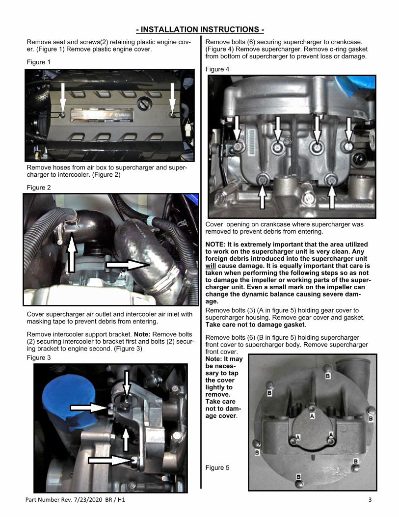
Remove hoses from air box to supercharger and super-charger to intercooler. (Figure 2)
Figure 2
Cover supercharger air outlet and intercooler air inlet with masking tape to prevent debris from entering.
Remove intercooler support bracket. Note: Remove bolts (2) securing intercooler to bracket first and bolts (2) secur-ing bracket to engine second. (Figure 3) Figure 3
Remove bolts (6) securing supercharger to crankcase. (Figure 4) Remove supercharger. Remove o-ring gasket from bottom of supercharger to prevent loss or damage.
Figure 4
Cover opening on crankcase where supercharger was removed to prevent debris from entering.
NOTE: It is extremely important that the area utilized to work on the supercharger unit is very clean. Any foreign debris introduced into the supercharger unit will cause damage. It is equally important that care is taken when performing the following steps so as not to damage the impeller or working parts of the super-charger unit. Even a small mark on the impeller can change the dynamic balance causing severe dam-age. Remove bolts (3) (A in figure 5) holding gear cover to supercharger housing. Remove gear cover and gasket. Take care not to damage gasket.
Remove bolts (6) (B in figure 5) holding supercharger front cover to supercharger body. Remove supercharger front cover. Note: It may be neces-sary to tap the cover lightly to remove. Take care not to dam-age cover.
Figure 5
Part Number Rev. 7/23/2020 BR / H1 4
er and shaft housing. Late model superchargers have a two-piece rear cover with a separate shaft housing. (Figures 8 and 9) Because of those differences, disassembly of the two supercharger models is different. Figure 8
Figure 9
Insert Supercharger Shaft Holder Tool into rear of super-charger and over gear. (Figure 6) Figure 6
While holding supercharger shaft tool in place apply heat to impeller nut to melt OEM thread locker. Impeller nut has LH threads. Using a 10mm wrench turn nut clockwise to loosen and remove. (Figure 7) Figure 7
Remove supercharger impeller. Note: It may be neces-sary to apply a little heat to the impeller to get it off the shaft. Use a heat gun or hair dryer. Do not use a torch! Heat carefully and twist the impeller while pull-ing it off the shaft. Yamaha superchargers installed on craft up to early 2018 models are different from superchargers in-stalled or sold for replacement parts after that date. Early model superchargers have a one-piece rear cov-
Part Number Rev. 7/23/2020 BR / H1 5
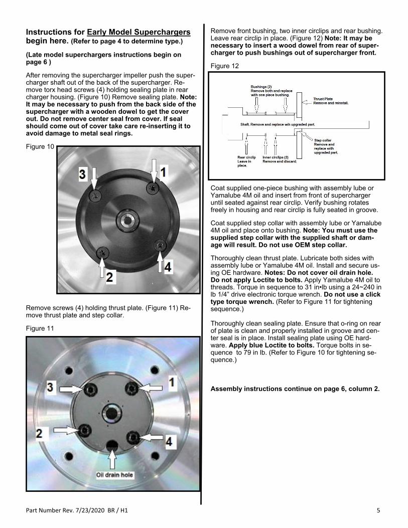
Remove front bushing, two inner circlips and rear bushing. Leave rear circlip in place. (Figure 12) Note: It may be necessary to insert a wood dowel from rear of super-charger to push bushings out of supercharger front.
Figure 12
Coat supplied one-piece bushing with assembly lube or Yamalube 4M oil and insert from front of supercharger until seated against rear circlip. Verify bushing rotates freely in housing and rear circlip is fully seated in groove.
Coat supplied step collar with assembly lube or Yamalube 4M oil and place onto bushing. Note: You must use the supplied step collar with the supplied shaft or dam-age will result. Do not use OEM step collar.
Thoroughly clean thrust plate. Lubricate both sides with assembly lube or Yamalube 4M oil. Install and secure us-ing OE hardware. Notes: Do not cover oil drain hole. Do not apply Loctite to bolts. Apply Yamalube 4M oil to threads. Torque in sequence to 31 in•lb using a 24~240 in lb 1/4” drive electronic torque wrench. Do not use a click type torque wrench. (Refer to Figure 11 for tightening sequence.) Thoroughly clean sealing plate. Ensure that o-ring on rear of plate is clean and properly installed in groove and cen-ter seal is in place. Install sealing plate using OE hard-ware. Apply blue Loctite to bolts. Torque bolts in se-quence to 79 in lb. (Refer to Figure 10 for tightening se-quence.) Assembly instructions continue on page 6, column 2.
Instructions for Early Model Superchargers begin here. (Refer to page 4 to determine type.)
(Late model superchargers instructions begin on page 6 )
After removing the supercharger impeller push the super-charger shaft out of the back of the supercharger. Re-move torx head screws (4) holding sealing plate in rear charger housing. (Figure 10) Remove sealing plate. Note: It may be necessary to push from the back side of the supercharger with a wooden dowel to get the cover out. Do not remove center seal from cover. If seal should come out of cover take care re-inserting it to avoid damage to metal seal rings.
Verify bushing rotates freely in housing and rear circlip is fully seated in groove.
Coat supplied step collar with assembly lube or Yamalube 4M oil and place onto bushing. Note: You must use the supplied step collar with the supplied shaft or dam-age will result. Do not use OEM step collar.
Thoroughly clean thrust plate. Lubricate both sides with assembly lube or Yamalube 4M oil. Install and secure us-ing OE hardware. Note: do not apply loctite to bolts. Apply Yamalube 4M oil to threads. Torque in sequence to 31 in•lb using a 24~240 in lb 1/4” drive electronic torque wrench. Do not use a click type torque wrench. (Refer to Figure 16 for tightening sequence.) Verify that o-ring on front of shaft housing is clean and properly installed in groove. Thoroughly clean super-charger rear housing. Assure that center seal is in place. Align housing as shown in Figure 15. Install rear housing using OE hardware. Apply blue loctite to bolts. Torque bolts in sequence to 79 in lb. (Refer to Figure 15 for tight-ening sequence.)
Assembly Procedure for both Early and Late Model Superchargers
Thoroughly clean supplied supercharger shaft. Coat shaft liberally with assembly lube or Yamalube 4M oil. Insert shaft from rear of supercharger through bushing, step col-lar, and center seal. Spin supercharger shaft to verify it does not bind. Insert Supercharger Shaft Holder Tool to lock shaft from turning. Warm supercharger impeller with a heat gun. While holding shaft and tool in place slip impeller onto shaft until it contacts center seal. Thoroughly clean supplied nut and threads on shaft. Apply red loctite onto threads inside nut only. Install nut onto shaft. Note: Nut and shaft have left hand threads. Turn nut counter-clockwise to tighten. Hold Supercharger Shaft Holder Tool fully engaged onto gear. Using an elec-tronic in·lb torque wrench and 6-point socket tighten nut securing supercharger impeller to shaft by ROTATING COUNTER CLOCKWISE. Torque nut to 115 in·lb Do not use a click type or ft lb. torque wrench. Spin impel-ler to veify it does not bind. (Figure 17) Figure 17
Instructions for Late Model Superchargers begin here. (Refer to page 4 to determine type.)
(Early model superchargers instructions begin on page 5 )
Remove bolts (4) holding supercharger rear housing onto shaft housing. (Figure 15) Separate housings. Note: It may be necessary to tap lightly on housings to sepa-rate. Do not damage sealing surfaces. Do not remove center seal from cover. If seal should come out of cover take care re-inserting it to avoid damage to met-al seal rings
Figure 15
Remove bolts (4) retaining inner cover. (Figure 16) Re-move thrust plate, step collar and bushing. Do not re-move snap ring.
Figure 16
Thoroughly clean shaft housing. Coat supplied one-piece bushing with assembly lube or Yamalube 4M oil and insert from front of supercharger until seated against rear circlip.
Part Number Rev. 7/23/2020 BR / H1 7
Apply pipe thread sealant to ‘male pipe threads’ on sup-plied 45-degree oil line fitting. Install into billet lubrication cover plate. Tighten until open end of fitting faces super-charger housing (forward). (Figure 21) Figure 21
On exhaust side of engine crankcase remove bypass hose from fitting at top of oil cooler. (Figure 22)
Figure 22
Clean mating surfaces of front and rear supercharger housing. Apply a thin coat of Yamabond 4 or Three Bond 1211 sealer to one side and assemble supercharger housing. Note: Do not over apply sealer. A thin coat is all that is required. (Figure 18)
Figure 18
Verify that supercharger is assembled as shown. (Figure 19) Outlet must point up and away from mating surface with engine block. Secure with OE hardware. Note: Apply blue Loctite to bolt threads. Torque bolts to 14 ft lb. fol-lowing sequence shown.
Figure 19
Transfer gasket from OE gear cover to supplied billet gear cover. Secure cover using supplied 6 x 20 mm FHS (3). NOTE: Apply blue Loctite to screws. Torque screws to 6 ft·lb. (Figure 20)
Figure 20
Part Number Rev. 7/23/2020 BR / H1 8
Reconnect oil pressure switch electrical wire and replace rubber boot. Apply Yamalube 4M engine oil to JIC threads of fitting installed on supercharger. Install 90-degree JIC fitting of supplied braided oil line onto supercharger fitting. Align braided line and tighten fitting. (Figure 26) NOTE: Secure fitting on supercharger before applying final torque to braided line fitting. On top of supercharger gear housing remove the small bolt and gasket (washer). (Figure 26) While rotating su-percharger impeller slowly add Yamalube 4M engine oil to pre-lubricate impeller shaft. Inspect gasket (washer). If deformed or severely crushed replace with new gasket (washer). Order part# 6S5-14199-00-00. Install bolt and gasket (washer). NOTE: Do not apply Loctite. Torque bolt to 3 ft·lb. Figure 26
Inspect underside of supercharger shaft housing. Reinstall o-ring in groove. Make certain all is clean and there are no foreign objects present. Apply a thin layer of grease onto o-ring. Install supercharger unit onto engine. NOTE: Make sure locator pins (2) are in place between supercharger and motor. Secure using OE hardware. NOTE: Apply blue Loctite to bolts. Torque the four M8 bolts to 14.8 ft·lb and the two M6 bolts to 7.4 ft·lb. (Figure 27) Figure 27
Install supplied billet ‘T’ fitting into engine crankcase (figure 25). Tighten until side of fitting with machined dot faces rear of en-gine/craft. NOTE: Apply pipe thread sealant to male pipe threads. Do not over tighten billet ’T’ fitting. Install supplied 45-degree oil line fitting into billet ‘T’ fitting. Tighten until open end of fitting faces down. Install oil pressure switch into billet ’T’ fitting. (Figure 25) NOTE: Apply pipe thread sealant to male pipe threads. Do not over tighten fitting and pressure switch.
Part Number Rev. 7/23/2020 BR / H1 9
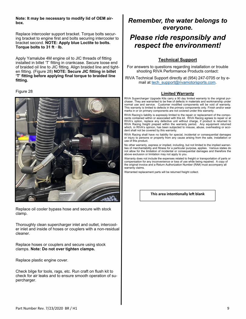
Note: It may be necessary to modify lid of OEM air-box. Replace intercooler support bracket. Torque bolts secur-ing bracket to engine first and bolts securing intercooler to bracket second. NOTE: Apply blue Loctite to bolts. Torque bolts to 31 ft · lb. Apply Yamalube 4M engine oil to JIC threads of fitting installed in billet ‘T’ fitting in crankcase. Secure loose end of braided oil line to JIC fitting. Align braided line and tight-en fitting. (Figure 28) NOTE: Secure JIC fitting in billet ‘T’ fitting before applying final torque to braided line fitting. Figure 28
Replace oil cooler bypass hose and secure with stock clamp. Thoroughly clean supercharger inlet and outlet, intercool-er inlet and inside of hoses or couplers with a non-residual cleaner. Replace hoses or couplers and secure using stock clamps. Note: Do not over tighten clamps. Replace plastic engine cover. Check bilge for tools, rags, etc. Run craft on flush kit to check for air leaks and to ensure smooth operation of su-percharger.
Remember, the water belongs to everyone.
Please ride responsibly and respect the environment!
Technical Support
For answers to questions regarding installation or trouble shooting RIVA Performance Products contact:
RIVA Technical Support directly at (954) 247-0705 or by e-mail at [email protected].
Limited Warranty
RIVA Supercharger Upgrade Kits carry a 90 day limited warranty to the original pur-chaser. They are warranted to be free of defects in materials and workmanship under normal use and service. Customer modified components will be void of warranty. This warranty is limited to defects in the primary components only. Finish and/or wear marks in or on primary components are not covered under this warranty.
RIVA Racing’s liability is expressly limited to the repair or replacement of the compo-nents contained within or associated with this kit. RIVA Racing agrees to repair or at RIVA’s option, replace any defective unit without charge, if product is returned to RIVA Racing freight prepaid within the warranty period. Any equipment returned which, in RIVA’s opinion, has been subjected to misuse, abuse, overheating or acci-dent shall not be covered by this warranty.
RIVA Racing shall have no liability for special, incidental or consequential damages or injury to persons or property from any cause arising from the sale, installation or use of this product.
No other warranty, express or implied, including, but not limited to the implied warran-ties of merchantability and fitness for a particular purpose, applies. Various states do not allow for the limitation of incidental or consequential damages and therefore the above exclusion or limitation may not apply to you.
Warranty does not include the expenses related to freight or transportation of parts or compensation for any inconvenience or loss of use while being repaired. A copy of the original invoice and a Return Authorization Number (RA#) must accompany all warranty claims.
Warranted replacement parts will be returned freight collect.