40
NAVAL STRUCTURAL MATERIALS: REQUIREMENTS, ISSUES, AND OPPDRTUNI-ETCIU) APR Al L R HETTCHE' A I SCHINDLER UNCLASSIFIED NRL-MR-4484 N .'rzuuuuuuurnuul Ifill/lfll/ll I//EEEE//EEEL
| Date post: | 21-Mar-2018 |
| Category: |
Documents |
| Upload: | truongthuan |
| View: | 218 times |
| Download: | 2 times |

NAVAL STRUCTURAL MATERIALS: REQUIREMENTS, ISSUES, AND OPPDRTUNI-ETCIU)APR Al L R HETTCHE' A I SCHINDLER
UNCLASSIFIED NRL-MR-4484 N.'rzuuuuuuurnuulIfill/lfll/ll
I//EEEE//EEEL

5ECu.UITY CLASSIFICATION OF THIS PAGE ("oen Data Entered)BEFORE IOMLETINSFRM
REPORT DOCUMENTATION PAGEA,1+ e J/ B RED COMPLETINGSI. REPORT NUMBER .e.mm 4 a.wumjji7
NRL Memorandum Report 4484 %
4. TITLE (and Subtitle) 6 ----------- CMT &1PRE9 OVERED
, AVAL ITRUCTURAL k ATERIALS: E REQUIREMENTS, T c e
ISSUES, AND OPPORTUNITIES Tpc Report-. . .. . .. S. PERFORMING ORG. REPORT NUMBER
7. AUTNOR(.) -TRACT OR GRANT NUMBER(&)
9. PERFORMING ORGANIZATION NAME AND ADDRESS 10. PROGRAM ELEMENT, PROJECT. TASK
Naval Research Laboratory AREA a WORK UNIT NUMBERSWashington, DC 20375 66356/6010- 66356/6010
It CONTROLLING OFFICE NAME AND ADDRESS 12. REPORT DATE
Office of Naval Research 8 - 10 April 1981Arlington, VA 22217 13. NUMBER OF PAGES
3714. MONITORING AGENCY NAME & ADORESS(Ilf different from Controlling Office) 15. SECURITY CLASS. (of thle report)
UNCLASSIFIEDS1a. DECL ASSI FI CATION/ DOWN GRADING
SCHEDULE
16. DISTRIBUTION STATEMENT (of this Report)
Approved for public release; distribution unlimited.
17. DISTRIBUTION STATEMENT (of the abstracl entered In Block 20, if different from Report)
IS. SUPPLEMENTARY NOTES
Prepared for presentation at the North Atlantic Treaty Organization (NATO)/Defense ResearchGroup (DRG) Seminar on Advances in Structural Materials in Relation to Defense Applications.
19 KEY WORDS (Continue on reverse aide If neceseay and Identify by block number)Naval structural material Crack tolerant properties Corrosion Particle injectionHigh performance ships Ion implantation Surface propertiesV/STOL aircraft Laser surface modification Surface alloyingNaval vehicles Fracture WearCrack tolerant properties Fatigue Friction
20 ABSTRACT (Continue on reree side It neceesary and Identify by block number)
'Ihis paper presents selective examples of requirements, issues, and opportunities associated withnaval structural materials. In particular, the relationships between operational capabilities andstructiral material requirements are examined for the following Naval systems: future high perfor-mance ships, next generation V/STOL aircraft, and conventional ships. These systems are selectedfor review because of the differences in their time frames for operational deployment.
(Continues) J
DD I jAN7 1473 EDITION O V00 o OBSLETE(S/N 0102-LF-014-6601 i 'i .. ,
SECURITY CLASSIFICATION OF THIS PAGE (when awe Enlered)
/' " o-
SECURITY CLASSIFICATION Of THIS PACE ("itan Doa RAntere
20. Abstract (Continued)
-7 Because of paper length consideration, the discussions on technical issues and R&Dopportunities are limited respectively to high strength marine alloys and emergent surface modi-fication techniques of ion implantation and laser beam processing. Here the ability to controland predict an exacting trade off in engineering properties and service behavior is identified as akey technical issue in developing improved alloy systems. Moreover, ion implantation and laserbeam processing offer the capability to optimize independent surface and bulk propertieswithout the discontinuous interface of conventional coatings as well as to minimize the use ofscarce or otherwise expensive materials. These discussions provide examples of structuralmaterials development at various stages of technological maturity and therefore at variousproximities from system impact.
SECuRITY CLASIFICATION OF THIS PAGElMben Data RntoE*
_ ° •
CONTENTS
PAGES
I. INTRODUCTION ... .. .. .. .. .. ...... . .
I. STRUCTURAL MATERIAL REQUIREMENTS OF SELECTED NAVAL
SYSTOL Aircraft. .. .. .. .. .. .. . . . .* . .. 3
e Conventional Ships .. ............ . . . . . . . 4
III. R&D OPPORTUNITIES FOR IM4PROVED PERFORMANCE OF HIGH
STRENHHMARI N EALLYSLOY.. S.. .. .. .......... 8
*Technical Issues ......................... * B
*Ion Implantation .. . . .. .. .. .. .. .. .. . . . 12
IV Laser Surface Modification... o. . . .... .*. . . . . . . . .19
IV SJNMA.RY STATEMENTo.................................30
V. ACKNOWLEDGEMENTS . . . ...... o- o. .. .. oo.. .. .... 30
VI. REFERENCES .. ........... .. o.. .. .o. .. ...... 31
A ccession Fo r
NTIS GRA&IDTIC TAB
Unzannounced QJustificatio
Distribution/-----_
Availability Codes
Avail and/or
Dist Special

NAVAL STRUCTURAL MATERIALS: REQUIRF24ENTS, ISSUES, AND OPPORTUNITIES
L. R. Hettche and A. I. Schindler
Naval Research Laboratory
Washington, D. C. 20375
INTRODUCTION
Improvements in structural materials technology over the remainderof this century pose one of the more important and certainly one of themost challenging areas of Naval research and development. This f orecastis based, in part, on the findings of a recently completed investmentstrategy for management of the U.S. Navy's materials R&D resources. De-veloped under the aegis of the Chief of Naval Development, this study, theso called Materials Technology Strategy, identified potential impact ofmaterials technology on Navy and Marine Corps operational capabilities,as well as deficiencies and R&D opportunities.
Foremost among these findings is the pervasive and often criticalrole structural materials play in defining the military effectiveness ofNaval vehicles and weapon systems. Most often, the development of newand improved operational capabilities is dependent in varying degrees onthe development of new and improved structural materials. In addition,there are urgent requirements for structural materials and productiontechniques which will improve availability, damage tolerance and surviva-bility, while reducing cost of most major systems. Finally, criticalmaterials availability, energy conservation, and environmental and safetyregulations are emergent issues which will place increasing demands on
* future structural materials technology.
Another strategy indicator of the potential impact of structuralmaterial technology on future systems comes from the pairing of key tech-nical issues and R&D opportunities. Here, the picture which emerges is oneof accelerated application of the interdisciplinary approach of modernmaterial science to the development of new and improved structural materialstechnology and the accelerated transfer of this technology to the design,fabrication, and maintenance schedule of future systems. In many ways, ourability to supply improved and innovative structural materials in a timelyand affordable way will be an important factor in determining the types,-4 numbers, and mix of future vehicles and platforms.
In accordance with the strategy rationale, this paper presents selectiveexamples of requirements, issues, and opportunities associated with navalstructural materials. In particular, the relationships between operational
Manuscript submitted February 6, 1981.
1oit_
capabilities and structural material requirements are examined for thefollowing Naval systems: future high performance ships, next generationV/STOL aircraft, and conventional ships. These systems are selected f orreview because of the differences in their time frames for operationaldeployment. Because of paper length consideration, the discussions ontechnical issues and R&D opportunities are limited respectively to highstrength marine alloys and emergent surface modification techniques of ionimplantation and laser beam processing. Here the ability to control andpredict an exacting trade off in engineering properties and service behavioris identified as a key technical issue in developing improved alloy systems.Moreover, ion implantation and laser beam processing offer the capability tooptimize independent surface and bulk properties without the discontinuousinterface of conventional coatings as well as to minimize the use of scarceor otherwise expensive materials. These discussions provide examples ofstructural materials development at .rious stages of technological maturityand therefore at various proximities from system impact.
From the admittedly incomplete survey of L.ipics covered in this paper,it is hoped that the diversity and complexity of the challenges facing theNavy's structural materials community over the next several decades willbecome manifest.
STRUCTURAL MATERIAL REQUIREM4ENTS OF SELECTED NAVAL SYSTEMS
High Performance Ships
High performance hydrofoils, surface effect ships (SES), air cushionvehicle (ACV) and other advanced vehicles utilized structural and machinerymaterials to their performance limits. The primary operational utility ofthese vehicles in comparison with conventional ships Is their high speedsand in some cases enhanced sea-keeping behavior. Depending on the lift andinstalled horsepower of various designs, these vehicles have demonstratedand projected speeds in the range of 50 to 100 knots. However, because ofthe high horsepower and high specific fuel consumption, the payloads ofthese vehicles are penalized relative to conventional designs. The so-called useful load (fuel and payload) of advanced ships, approximately 50%of the full gross weight, is strongly dependent on the structural weightfraction and to a lesser extent on machinery and lift system weights.Accordingly, the operational capabilities of advanced ships are dependent onthe availability of high performance structural materials.
To date, advanced ships built by the U.S. Navy have been test andevaluation platforms (SES-1QO and PCH-1 hydrofoil) and special purpose craft
(P1*1 hydrofoil) of 50 to 200 tons. The hull structures of these craft arepredominantly welded construction of 5000 marine series aluminum alloys.The struts and foils of hydrofoils have utilized a variety of high strengthalloys, including HY-steels, PH stainless steels, and titanium. Althoughmaterials problems have appeared in these applications, the general materialsperformance is judged as adequate.
4 2
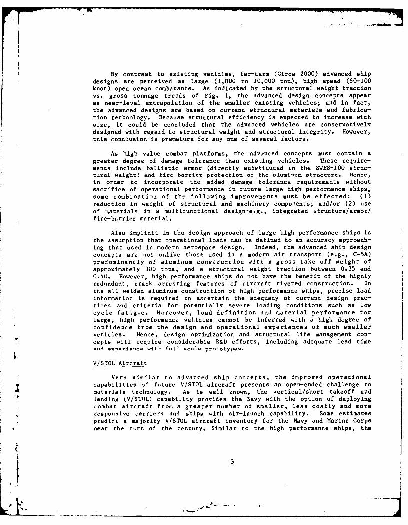
By contrast to existing vehicles, far-term (Circa 2000) advanced shipdesigns are perceived as large (1,000 to 10,000 ton), high speed (50-100knot) open ocean combatants. As indicated by the structural weight fractionVS. gross tonnage trends of Fig. 1, the advanced design concepts appearas near-level extrapolation of the smaller existing vehicles; and in fact,the advanced designs are based on current structural materials and fabrica-tion technology. Because structural efficiency is expected to increase withsize, it could be concluded that the advanced vehicles are conservativelydesigned with regard to structural weight and structural integrity. However,this conclusion is premature for any one of several factors.
As high value combat platforms, the adv-nced concepts must contain agreater degree of damage tolerance than exis:ing vehicles. These require-ments include ballistic armor (directly subvtiuuted in the SWES-100 struc-tural weight) and fire barrier protection of the alumiium structure. Hence,in order to incorporate the added damage tolerance requirements withoutsacrifice of operational performance in future large high performance ships,some combination of the following improvements must be effected: (1)reduction in weight of structural and machinery components; and/or (2) useof materials in a multifunctional design-e.g., integrated structure /armor/f ire-barrier material.
Also implicit in the design approach of large high performance ships isthe assumption that operational loads can be defined to an accuracy approach-ing that used in modern aerospace design. Indeed, the advanced ship designconcepts are not unlike those used in a modern air transport (e.g., C-5A)predominantly of aluminum construction with a gross take off weight ofapproximately 300 tons, and a structural weight fraction between 0.35 and0.40. However, high performance ships do not have the benefit of the highlyredundant, crack arresting features of aircraft riveted construction. Inthe all welded aluminum construction of high performance ships, precise loadinformation is required to ascertain the adequacy of current design prac-tices and criteria for potentially severe loading conditions such as lowcycle fatigue. Moreover, load definition and material performance forlarge, high performance vehicles cannot be inferred with a high degree ofconfidence from the design and operational experiences of much smallervehicles. Hence, design optimization and structural life management con-cepts will require considerable R&D efforts, including adequate lead timeand experience with full scale prototypes.
V/STOL Aircraft
Very similar to advanced ship concepts, the improved operationalcapabilities of future V,'STOL aircraft presents an open-ended challenge toma3terials technology. As is well known, the vertical/short takeoff andlanding (V/STOL) capability provides the Navy with the option of deployingcombat aircraft from a greater number of smaller, less costly and moreresponsive carriers and ships with air-launch capability. Some estimatespredict a majority V/STOL aircraft inventory for the Navy and Marine Corps
* near the turn of the century. Similar to the high performance ships, the
13
.1A
range and payload of V/STOL aircraft are curtailed relative to conventionalcarrier aircraft. The most direct approach to improving the operationaleffectiveness of future V/STOL aircraft is the introduction of improvedmaterials and design concepts in either or both the airframe and the engine.
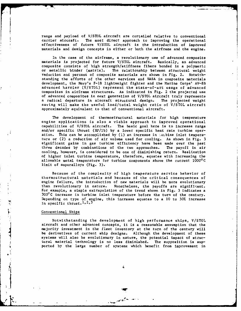
In the case of the airframe, a revolutionary use of advanced compositematerials is projected for future V/STOL aircraft. Basically, an advancedcomposite consists of high strength/stiffness fibers bonded in a polymericor metallic binder (matrix). The relationship between structural weightreduction and percent of composite materials are shown in Fig. 2. Notwith-standing the efforts of the other services and NASA in composite materialsdevelopment, the Navy's F-18 lightweight fighter and the Marine Corps' AV-8Badvanced harrier (V/STOL) represent the state-of-art usage of advancedcomposites in airframe structures. As indicated in Fig. 2 the projected useof advanced composites in next generation of V/STOL aircraft truly representsa radical departure in aircraft structural design. The projected weightsaving will make the useful load/total weight ratio of V/STOL aircraftapproximately equivalent to that of conventional aircraft.
The development of thermostructural materials for high temperatureengine applications is also a viable approach to improved operationalcapabilities of V/STOL aircraft. The basic goal here is to increase rangeand/or specific thrust (HP/lb) by a lower specific heat rate turbine oper-ation. This can be accomplished by (1) an increase in .uibine inlet tempera-ture or (2) a reduction of air volume used for cooling. As shown in Fig. 3significant gains in gas turbine efficiency have been made over the pastthree decades by combinations of the two approaches. The payoff in aircooling, however, is considered to be one of diminishing return. Realizationof higher inlet turbine temperature, therefore, equates with increasing theallowable metal temperature for turbine components above the current 10000 Climit of superalloys (Fig. 3).
Because of the complexity of high temperature service behavior ofthermostructural materials and because of the critical consequences ofengine failure, the introduction of new materials will be more evolutionarythan revolutionary in nature. Nonetheless, the payoffs are signifPeant.For example, a simple extrapolation of the trend shown in Fig. 3 indicates a3000 C increase in turbine inlet temperature before the turn of the century.Depending on type of engine, this increase equates to a 10 to 30% increasein specific thrust.
1 ,2' 3
Conventional Ships
Notwithstanding the development of high performance ships, V/STOLaircraft and other advanced concepts, it is a reasonable assumption that themajority investment in the fleet inventory at the turn of the century willbe derivatives of current ship designs. Although the development of thesesystems will also be evolutionary in nature, the potential impact of struc-tural material technology is no less diminished. The supposition is sup-ported by the large number of systems which benefit from improvement in
4
'S - .~
Z 0.5 -_EXISTING ADVANCED DESIGN2 VEHICLES CONCEPTS40.4 -ACV AND SES TREND
ALA
2 -H~YDR-OFOIL i R ..... -- -i0.2 ,,DRu~ TREND (WITHOUT STRUT AND FOILS
I-o0 100 1,000 10,0oo
GROSS WL!GHT (TONS)
Fig. I Comparison of structural weight fraction versus gross weightfor existing (closed symbols) and advanced design concepts(open symbols); air cushion vehicles, ACV, 0; surface effectships, SES, a; and hydrofoil, 0.
2
F 15- PROJECTED USE OFCOMPOSITES FORADVANCED V/STOL REQ'D.s
LU
'10
,F-18
I-O
0 10 20 30 40 50
COMPOSITE MATERIALSPERCENT TOTAL STRUCTURAL WEIGHT
Fig. 2 Relationship between structural weight reduction and compositematerial usage in advance airframe structures. Projected useof composite materials for advanced V/STOL requirements indicated.
5

3200~ 1700
28M -50A. ITEMPERATURE LIMIT FOR -_
AIR COOLED SUPERALLOYS2400 13D
IL 2000 - ALLOWABLE METAL -1100 CLTEMPERATURE
S'FOR CURRENT SUPERALLOYS -90160-COMPONENTS -
1200 -7001950 1960 1970 1980 2000
YEAR
Fig. 3 Trend in military aircraft turbine inlet temperature; andallowable metal temperature for current superalloys.
materials technology. Moreover, current trends indicate a shift of R&Dpriorities and emphasis from performance requirements to other factorsaffecting military-worth, such as damage tolerance and survivability,availability, and that nemesis of all defense systems-costs.
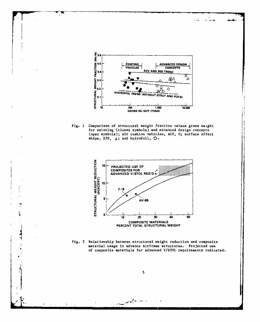
The requirement for improved damage tolerance and survivability wasmade apparent in the 1975 collision of the aircraft carrier John F. Kennedyand the cruiser BELKNAP. The melted remains of the cruiser's aluminumsuperstructure are shown in Fig. 4. Only the steel frame remains erect.The lightweight aluminum superstructure of conventional ships is a postWorld War Il innovation and, therefore, has not been combat tested. More-over, fire hazard susceptibility as well as ballistic damage tolerance werealso cited as issues in the combat worthiness of the predominantly aluminumconstruction of advanced surface ships. Hence, the continual developmentand innovative use of affordable fire resistant coatings, insulation mate-rials, lightweight armor and improved structural materials are required tosustain the improved performance obtained by aluminum alloys in ship con-struction.
Another example of the potential impact of structural materials tech-nology on the operational capabilities of conventional ships is the marinegas turbine engine - the adopted prime mover for U.S. Navy non-nuclearsurface ships. Because of prohibitive cost associated with the develoilaentof an altogether new engine design, the U.S. Navy's design approach bas beento modify an existing aircraft turbojet engine. 2 Previous experience in-dicates that the life limiting factors of marine gas turbines are hot cor-rosion of components in the high temperature section. Accordingly, themajor modifications in the so-called "marinizing" of the aircraft engine are
6
Fig. 4 The fire damage of the aluminum superstructure of the cruiserBELKNAP after collision with the aircraft carrier JFK in 1975.
the substitution of more corrosion resistant alloys and coatings and thereduction of the maximum operating temperature. Similar to aircraft enginedesign, the decrease in operating temperature results in a performancepenalty.
Although the marinizing approach is prudent in terms of economic andengineering considerations, early sea trials of the resulting prototypeengine revealed an unanticipated form of severe corrosion attack of theturbine blade at low power operations. In contrast to the more common hotcorrosion which gives significant attack above 1550 0F, the low power corro-sion occurred at temperatures in the range of 1200 - 1400OF and limited bladelife to an unacceptable duration. 4 Subsequent improvements in the bladecoating and the filtering and ducting system has increased blade life to anacceptable level of 5000 hours.
Nonetheless, the aggregate effect of hot corrosion in the low and highpower operation reqimes remains as the life limiting factor of the marine gasturbine. Accordingly, the introduction of improved hot corrosion resistantalloys and coatings into the hot sections directly equates to increasedengine life and correspondingly increased availability of the host platform.Moreover, improvement in hot corrosion resistance of these components will beinsurance against other contingencies, such as premature degradation of thefiltering system by improper maintenance or operation or by emergency/wartimedamage, as well as the potentially harmful effects of substandard (e.g., highsulphur) or synthetic fuels.
7

The abovo -,,inmentary on high performance ships, V/STOL aircraft, andconvenlional ships is intended to illustrate the structural materials require-ments of far-term, next generation, and operational systems, respectively.These discussions could have included other important and equally materialsdependent systems, such as submersible, missiles, amphibious and armorvehicles. Rather than extend these discussions adinfinitum, however, atten-tion is now directed toward technical issues and R&D opportunities associatedwith high strength marine alloys. As previously noted, the topics selectedfor review in the following sections are considered representative of struc-tural materials developments with near-to-fa:-term impact. (In addition,these topics compliment well other U.S. papers at this seminar)
R&D OPPORTUNITIES FOR IMPROVED PERFORMANCE OF HIGH STRENGTH MARINE ALLOYS
Technical Issues
Notwithstanding the positive gains made in the utilization of advancedorganic composite materials over the past decade and the optimistic forecastfor the development of metal matrix composites, it is a reasonable assumptionthat the vast majority of structural material utilized in high performancenaval applications will be derivatives of current ferrous, aluminum andtitanium base alloys. Moreover, the major technical issue in developingimproved alloy systems (or even in the optimum utilization of existingalloys) is the ability to predict and control an exacting trade off of theirengineering properties and service behaviors.
As is well known, the structural efficiency of alloys and weldmentsystems is directly proportional to allowable design stresses at which thesematerials can be incorporated into a structure. The design stress for highstrength alloys, however, are typically a fraction (1/5 to 1/2) of the yieldstrength which in turn are only a fraction of the strength which is metallur-gically obtainable. The seemingly conservative (low) design stresses of highstrength alloys are dictated by their defect and cracking sensitivity in themarine environment (for example fracture toughness, stress corrosion crack-ing, fatigue, corrosion fatigue, etc.) as well as their general corrosionresistance.
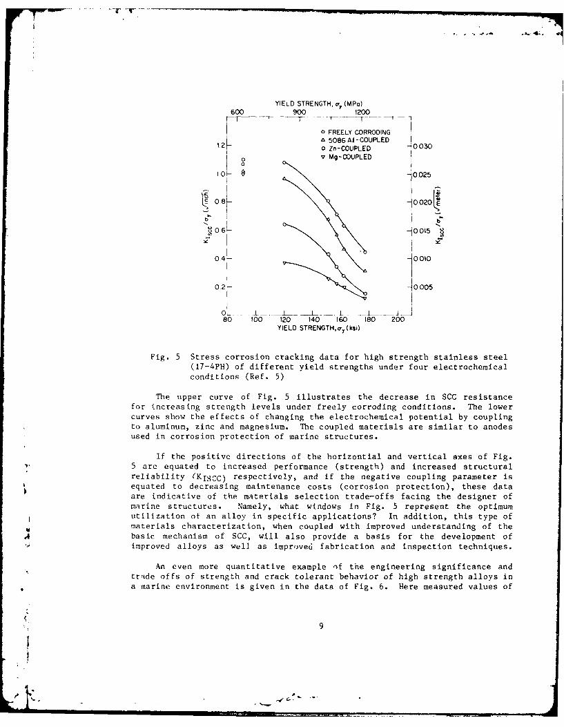
A quantitative example of the relationship between strength, cracktolerance and corrosion resistance for a precipitation hardened stainlesssteel (17-4PH) is given in Fig. 5.5 This alloy has been utilized for spe-cialized purposes in aircraft and rocket components and in certain marineapplications like struts and foils for hydrofoils because of the alloy'srelatively good corrosion resistance at high strength levels. The data
0 of Fig. 5 show the effects of electrochemical potential coupling on theA stress corrosion cracking resistance of this alloy, heat treated to various
strength levels. Stress corrosion cracking (SCC) resistance of an alloyis related to the initiation and growth of a crack at stress concentrationsites in the presence of a corrosive environment, and is measured by thefracture mechanics parameter KISCC. This parameter defines a thresholdcrack-tip stress state below which SCG will not occur in the test environment.Usually, the critical stress intensity value of KISCC for SCC is determinedexperimentally from sustained-load tests conducted on relatively small pre-cracked specimens immersed in saltwater.
8
46.
YIELD STRENGTH, o, (MPa)600 900 1200
, 0 FREELY CORRODING
1.2K& 5086A- COUPLED12 0 Zn-COUPLED 0030
v Mg-COUPLED
0D- -0025
c 0.8k- 0020
bb
0 r. -0015 8
04- 01
0 4 . 0 DID
0,2 - 0.005
O0 L_L _L_ I I I Io 100 120 140 160 180 200
YIELD STRENGTH,a-y (ksi)
Fig. 5 Stress corrosion cracking data for high strength stainless steel
(17-4PH) of different yield strengths under four electrochemical
conditions (Ref. 5)
The upper curve of Fig. 5 illustrates the decrease in SCC resistancefor increasing strength levels under freely corroding conditions. The lowercurves show the effects of changing the electrochemical potential by couplingto aluminum, zinc and magnesium. The coupled materials are similar to anodesused in corrosion protection of marine structures.
If the positive directions of the horizontial and vertical axes of Fig.5 are equated to increased performance (strength) and increased structuralreliability (KISCC) respectively, and if the negative coupling parameter isequated to decreasing maintenance costs (corrosion protection), these data
are indicative of the materials selection trade-offs facing the designer ofmarine structures. Namely, what windows in Fig. 5 represent the optimum
utilization ot an alloy in specific applications? In addition, this type of
materials characterization, when coupled with improved understanding of the.4 basic mechanism of SCC, will also provide a basis for the development of
improved alloys as well as improved fabrication and inspection techniques.
An even more quantitative example of the engineering significance and
trade offs of strength and crack tolerant behavior of high strength alloys ina marine environment is given in the data of Fig. 6. Here measured values of
9

the critical stress intensity factors for plane strain fracture toughness, KIC,and for stress corrosion cracking thresholds, KISCC, for steels and titaniumalloys have been plotted as a function of the measured yield strengths andthe calculated critical depths for a thumb nail type surface crack in alarge, unaxial stressed plate. In accordance with the fracture mechanicsrelationship between stress a and critical crack depths dc (KIc-vdZ)loci of constant stress intensity factors are shown as line of constant slopeon these log-log plots.
The data sets shown in Fig. 6 were abstracted from the literature6 andare considered representative, but by no means definitive, examples of thecrack tolerant behavior of these important class of structure alloys. Hence,no quantitative conclusions should be inferred from these data analysesalthough several broad brush trends can be observed. Namely, the cracktolerant behavior of these alloys is seen to depend on their strength and isseen to be extremely sensitive to the aqueous environment.
Through heat treatment, the yield strength of these alloys can be variedover a wide range of values. Increases in strength, however, are accompaniedon the average by a greater than proportionate decrease in the plane strainfracture toughness. As defined by the ASTM Standard E399, the plane strainfracture toughness is a material-toughness property measured in terms ofstress-intensity factor of a linear elastic medium. In this test procedure,KIC is based on the lowest load, that is lowest stress intensity, at whicha significant extension of the crack occurs. Hence, the KIC points of Fig.6 indicate the critical crack depths at which the hypothetical flawed platewill fail under yield stress loading. Because of square dependence of thecritical crack size on KIC, the fracture susceptibility of a component isdisproportionately increased as the yield strength of the alloy and/oroperating stress are increased. For example, the critical crack size for thestructural alloys decreased by an order of magnitude over the ranges of yieldstrength examined.
The data for two recently developed alloys, NAVAIR's CORONA-5 (Ti-4.5A1-5Mo-I.5Cr) and Air Force's AFI410 steel (Fe-14Co-lONi-2Cr), are shown respec-tively in the data sets of Fig 6. Both alloys were developed to meet theneeds of aerospace applications based on fracture mechanic design criteria 6
and represent significant increase in fracture toughness relative to these1972 data bases.
As previously defined, the KISCC data of Fig. 6 indicate the criticalcrack depth at which a crack will grow when the hypothetical flawed plate isimmersed in an aqueous solution (3.5% NaCl) and subjected to a yield stressloading. The value are seen to be anywhere from 2 to 100 times smaller thanathe critical crack sizes for fast fracture in identical materials.
By far the smallest critical defect sizes of Fig. 6, is related to theso-called fatigue stress intensity threshold, KTH. Here the critical sizeof defcrts, several orders of magnitude less than those which cause fastfracture, is determined by a lower bound stress intensity factor which must
10

-4co to
0to- ~40.
x -J 0 )1* V CC
00
0 '
16 iia V .- -4
AI Z -0
41e,-4 w000
(-11~I Hid OV IVWN 1VII:wi3O3H U -
04 C
cu. J1)-4 c
V. -4
o to A U
- N
0 - - v~ 0) Ai
a - '-4HI3 IVOIAW03H
be exceeded for fatigue crack to proprogate. Although the continuum assump-tion of fracture mechanics is suspect at this size scale, e.g., cracks lessthan 0.001 cm, these extrapolations do indicate the extreme cracking sensi-tivity of high strength alloys. It is also of interest to note that thesmallest size surface flaw which can be reliably and routinely detected bystate-of-art nondestructive inspection techniques in a production lineenvironment is usually in excess of 0.1 cm.
The data analyses of Fig. 5 and 6 not only illustrate the engineeringtrade offs which must be considered in the design of high strength alloycomponents and structures, but also are indicative of a critical element inthe development of improved alloy systems, that is the capability to quantita-tively predict the service performance of high strength alloys. Indeed, bycombining the predictive capabilities of advanced fracture mechanics andelectrochemical analyses with modern metallurgical principles and processingprocedures, it is now possible to design and tailor the properties of highstrength alloys for optimum service performance. As previously cited (seeFig. 6), the AF 1410 steel and CORONA-5 titanium alloy are examples of modernalloy development based on fracture mechanics criteria. The work of Yoderand co-workers on fatigue resistance7 of aerospace titanium alloys (Ti-6A1-4Vand Ti-8A1-lMo-1V) is also a noteworthy example of this approach. Heremicrostructural modification by post processing heat treatment have resultedin a 70 fold increase in the fatigue crack growth resistance of these alloys.In addition, the improvements in behavior can be rationalized in terms of themicrostructural modification and the crack tip stress state as defined by thefracture mechanic stress intensity factor.
Most recently the approach of tailoring or designing alloys for special-ized requirements has been enhanced with the emergence of two highly versatiletechniques for surface modification of metals and alloys, namely ion implan-tation and laser beam processing. As described in the following sections ofthis paper, these techniques now provided the means to optimize the oftencritical surface sensitive properties including, crack initiation, generalcorrosion, friction and wear.
Ion Implantation
Ion implantation in metals and alloys has experienced a rapid growthduring the past few years. Since the early 1970's there has been a signif-icant number of articles, papers, books and conferences devoted to non-electronic properties of ion implanted mate rials8 ' 9'10. Surface relatedproperties such as friction, wear, corrosion and fatigue-life of structuralmetals and alloys are found to improve as a result of ion implantation.Almost all surf ace-sens it ive, life-limiting properties of structural metalscan be modified by ion implantation. Furthermore, ion implantation hasseveral advantages such as: (1) the method is independent of diffusion-controlled processes and thus surface chemistry can be modified to anydesired fluence with any chemical species, (2) bulk properties related tostrength and toughness can be maintained at the desired values while optimiz-ing the surface chemistry and microstructure without a sharp interface, and,(3) use of relatively scarce metals can be minimized through surface alloying
by ion implantation.
j 12
Ion implantation is a process of electrically accelerating ions to highvelocities and directing them into the near-surface regions of metals and
alloys to produce in essence a different alloy in the near-surface region.
The method can indeed be utilized to produce a graded alloy from the surface
to the unchanged underlying bulk. Since the method is distinctly different
from coating or plating processes, there are no problems relating to adhesionor change of microscopic dimensions. The apparatus consists of an accelerator
which produces a high energy ion beam (usually at tens to hundreds of kilo-volts) of any preselected element. These ions are forcibly injected beneath
the surface of any material. This injection process produces an intimate
alloy of the implanted and the host elements without producing a sharp
interface characteristic of all coating processes. The resultant depth
distribution and alloy composition depend on the energy and the atomic number
of the projectile as well as on the atomic number of the host.
Typically, depths of hundreds to thousands of angstroms are achievable
with concentrations of up to 50%. Since it is not a thermodynamic process,metastable alloys can be formed without regard for solid solubility or
diffusivity. However, if chemical equilibrium is required, it can be achieved
by a suitable post heat-treatment. Depending on the characteristics of the
host metal and the implanted ion, metastable phases including amorphous
structures could be formed on the surface of crystalline substrates.
Fatigue Behavior: Early preliminary measurements on the effects of ion
implantation on fatigue properties are reported by Hartley l . Here rotat-ing bend tests on smooth, polished specimens of stainless steel and titanium
exhibited an eight to ten fold increase in fatigue life after a 200 keV,2xl0 7 per cm 2 implantation of nitrogen (N ) ions. Similar improvements
were also observed1 ' for flat specimens of maraging steel implanted with 2x 1(1 7 per cm 2 carbon dioxide ions (C0 2+) and tested under high cycle
fatigue conditions. it was also reported that the implanted specimens, incontrast to the unimplanted specimens, experienced a significant temperature
rise immediately before fracture. Following a suggestion by Thompson.'-, itis speculated that this effect is related to excess strain energy caused by
the impediment of dislocated motion in the implanted layer. Evidence to
support such a conjecture, however, are unavailable at this time.
Rotating bend tests have also been reported 1 3 on low-carbon steel(AISI 1018) specimen implanted with 75 keV, 2YI0 1 7 /cm 2 nitrogen ions. As
shown in Fig. 7, the fatigue life time of the nitrogen-implanted specimen
exhibited a larger variation than the unimplanted samples but no discernible
overall improvement. However, a substantial improvement in nitrogen sampleswere measured (column 3 of Fig. 7) after the specimens were room temperature
aged for approximately 4-months or artifically aged at O0°0 C for 6 hrs.,
(column 4 of Fig. 7). This aging treatment allows both the relaxation ofresidual surface stresses and The diffusion of nitrogen to depths three to
four time the as implanted depth of 0.1 micrometer. Subsequent transmission
microscopic study showed that large concentrations of 10nm precipitates of
13
!A

Fel 6 N2 form at the near surface region of the sample and presumably delayscrack nucleation. Further investigation is required to establish the mech-anism for the observed fatigue life improvement. To this end, it may beuseful to compare the fatigue life and microstructure of the nitrogen im-planted alloy with those of conventional nitriding.
Ion implantation has also been shown 14 to produce beneficial effectson the fatigue behavior of a-0 processed Ti-6A1-4V alloy. As shown in Fig. 8
A
implants of either carbon or nitrogen ions of 75 keV and 2x10' 7 atoms/cm
improves the high cycle fatigue life of this alloy as evidenced by theincrease in the endurance limit above unimplanted results. These data arefor rotating beam fatigue tccts of 1600cpm. In addition, the carbon implanta-tion data of Fig. 8 shows a significant improvement in the low cycle fatiguebehavior. In contrast to the previously discussed results for low-carbonsteel, heat treatment has only a small effect on the fatigue behavior ofeither type of implanted specimens.
Microstructural modification of the Ti-6AI-4V alloy from the prescribednitrogen and carbon tmplantation were studied 14 by iransmission electronmicroscopy. In the case of the nitrogen implants, the structure consisted ofa dense, poorly resolved damaged layer, with no indication of a second phase.At the same dose level, however, carbon implantation produced a high densityof second phase particle of approximately 10 to 20nm (Fig. 9a). After heattreatment of one hour at 400cC in ultra high vacuum, the second phase par-ticles density is increased, and the size range is now 20 to 50nm (Fig. 9b).Selected area diffraction pattern analysis of second phase particles indicatethe crystal structure to be titanium carbide (TIC). Reportedly, the occur-rence of second phase particles for the carbon but not the nitrogen may beattributed to the lower solubility and higher mobility of carbon over nitro-gen in titanium.
A noteworthy feature of the nitrogen implanted and unimplanted Ti-6A1-4Vfatigue specimens was revealed through examination of the fracture suifacesby the scanning electron microscope. For all specimens where the life timeexceeded 2xlO 5 cycles, the initiation site of the fatigue crack was between25 and 150 micrometer below the surface. Such subsurface cracking in tita-nium alloy has been observed by others 15. Because the depth of the im-planted layer is less than 0.1 micrometer, it was concluded that the N+
implantation has little or no effect on the crack initiation site but,nonetheless, does inhibit the crack growth toward the surface.
Corrosion: Ion implantation has been shown to have a profound effect onthe corrosion of a variety of metals and structural alloys, including tita-nium, stainless steels, and aluminum. Experiments have also shown that pureiron implanted with ions of Cr and Ni exhibit corrosion resistance identicalto stainless steels of comparable bulk composition. These results show thata corrosion protection layer can be formed on the surface of structuralalloys without building up the concentration of the entire bulk. 16 Accord-ingly, the ion implantation of alloys provides a unique method of minimizingthe use of supply-limited alloying elements without sacrificing properties.
14
-9-'-.
II I l II I vl

r 7-~
.
*MFLUENCE OF SPECIMENTREATMENT ON FATIGUE
UFETIME
(UNFAILED)
0
Fi.7Cycles-to-failure forM four diferent sc men IramnsoAISI 1018 steel. Rotating beam fitigue at 50 ksi.
o0 Ti -6A I-4V
00 . "
90-90- 0 -uNiMPLANTED N=- --
A - - IMPLANTED 2 It 10' N*vcm2
A
go - 0 IMPLANTED 2It11 C/CrP-d6
0 0~ 5'0 6 107
CYCLES TO FAILURE
Fig. *8 Cycles-to-failure versus applied stress for Ti-6A1-4V in arotating beam fatigue at l600cpm.
*1 j 15

(a) As Implante 200Q~OX
(b) AnnualI d I fil 1,O00"C 2o oOX
Fig. 9 Mic rost ructurctS et- Ti-6A1-4%V Implanted2xl0' / AT/cm2) Carbon Ions (C7+)
As a low-temperature process, implantation also offers potential ben-ef its for applications where conventional, high temperature coating processesproduce unacceptable bulk property changes. For example, the implantation ofchromium into a commerical maraging steel has been shown17 to improve thecorrosion resistance of this alloy without changes in bulk properties. Thehigh temperature required to apply a chromium layer by conventional diffusionprocesses would result in significant increase in grain size, which in turndegrades the strength and toughness of this alloy. Another example of thistype is given by results of high dose chromium implantation into a AlSl M50bearing steel.19 As shown in the macrographs of Fig. 10, the implantedalloy via the unimplanted alloy shows a significant improvement in thegeneral and localized corrosion when tested under laboratory-simulated fieldconditions. Here again surface modification requiring high temperatureswould unacceptably reduce the toughness of this bearing alloy. In addition,implantation produces no macroscopic dimensional changes and can be appliedto otherwise finished components.
Oxidation: Beneficial effects of ion implantatio~n on the high tempera-ture oxidation of alloys have also been explored in a number of investiga-tions. For example, oxidation rates of chromium rich stainless steels aresignificantly reduced by implantation of Yttrium and other rare earth ionsi9 .Similar results have been reported for titanium implanted with Ba, Co, andEu20. In this case oxidation was reduced at all temperatures. In theseexamples it is hypothesized that the formation of impermeable Perovekitestructures, such as YCrO3, LaCrO 3, BaT1O 3 inhibited thermal oxidation.In addition, reference has been made 2 1 to reducing the parzbolic rateconstant for oxidation of FeCrAlY alloy by Al ion implantation. Reportedly,this effect is related to formation of A1203 to concentrations not obtainableby bulk alloying.
Hardness: Several investigators have reported a significant increasein surface hardness of alloys resulting from ion implantation. Of course itshould be recognized that these hardness values are determined by measuringthe Vickers or Knoop hardness number, which consists of making diamondindentations several times deeper than the thickness of the implanted layer,and therefore, do not precisely represent the implanted surface hardness.
Most experiments have been done in pure iron or steels implanted withcarbon, nitrogen, argon and boron2 2' 2 3 . In all cases the surface micro-hardness improved due to implantation. The observed surface hardening hasbeen related to the probable formation of carbides or nitrides or to theradiation induced damage effects. It is interesting to note that inert gasessuch as Ar and Ne have no effect when implanted above 5001C, whereas room-
.4temperature implantation produces hardening. Boron-implanted berylliumsubstrates show significant promise for use in precision gas-bearing compo-nents. The components currently in use have a hard oxide coating whichexhibit adhesion problems.
Friction & Wear: Most of the work, all very preliminary, on the effectof ion implantation on friction has been conducted at Harwell. Measurements
17

UNIMPLANTED Cr*IMPLANTED
Fig. 10 Results of Laboratory -simulated field corrosion tests. Whenboth parts were the M50 alloy, the flat surface suffered severelocalized attack. A line of pits was located at the meniscuscenter, and additional pitting was observed in the thin layernear the edge of the flat surface. Ion implantation with Creliminated both areas of attack (right photograph).
of friction force between a tungsten carbide ball and case-hardened steel (IN3523 implanted with Mo, Sn, Pb, In and Kr at fluences between 1016 and101" ions/cm2 show encouraging results. The results show no effect ofKr, and increase for Pb and a decrease for Sn both by as much as 50%24.
Overlapping implantation of Mo and S significantly reduced frictionpresumably due to the formation Of MoS2. Ion implantation does provide anovel method of forming near-surface precipitates known for their solid-lubricant properties on a hard, wear resistant material.
Probably the most extensive study has been directed to study the improve-ment of wear due to ion implantation. Most of the wear tests have beencarried out with a pin-on-disk test under lubricated conditons. The wearrates of the rotating implanted disks were found to be significantly reducedby as much as a f actor of 30. Wear rates of several steels and bearingalloys implanted with N, C, Ar, Mo and Co has been determined by this method.
Advanced analytical techniques are currently being used for the inves-tigation of the implantation effects on wear, including Mossbauer spectro-scopy, Auger electron spectroscopy, transmission electron microscopy, scann-ing electron microscopy and wear particle analysis 2 5 . Results comparingthe unimplanted and implanted couples indicate that there is no significantchange in the shape or size distribution of the wear particles produced evenFthough they differ in quantity by a factor as high as several hundred.Although the fundamental features of the responsible mechanisms are notunderstood as yet, the results suggest that implantation reduces the initia-tion and growth rates of cracks formed during the wear process.
18
i1

Laser Surface Modifications
The high power densities attainable with laser beams have made possiblethe development of a wide range of surface modification techniques, includingtransformation hardening, laser glazing, surface alloying, laser cladding,consolidation of coatings, and laser melt/particle injection. Some of thesetechniques are adaptations of ones long popular in industry, while otherswere made possible by the rapid heating and cooling rates attainable withhigh power lasers. Transformation hardening is typical of those techniqueswhich are adapted from earlier practice. It utilizes the laser beam tobriefly heat the surface of a steel sample to austenitizing temperatures,permitting conduction cooling by the unheated base metal to quench the heatedzone and produce a hard, martensitic structure on the surface. The advan-tages which accrue from using laser (or electron-beam) heating rather thaninduction or flame heating are that minimal heating of the bulk material canprevent thermal degradation of bulk metal and can limit distortion of thepart during quenching26 .
Laser glazing27 differs from transformation hardening in that thesurface layer is melted, not simply cycled through a set of solid state phasetransformations. The melting and rapid resolidification makes possiblesurface hardening, through the refinement of microstructure, of a wide ran eof alloy types. It can, in some alloys, improve the corrosion resistance1
8
by eliminating or minimizing phase separation. Surface alloying, to bediscussed in detail subsequently, can improve both the corrosion and wearresistance of a wide range of alloy types. It does so by introducing alloy-ing elements which improve the corrosion resistance or which stabilize hard,wear resisting phases.
Laser cladding, a patented process 29 , is similar to traditional weldcladding processes in that it uses the energy of the laser beam to fuse ametallic overlayer and weld it to the surface of the base metal. The materialto be clad to the surface can be in the form of a loosely adhering powder orit can be wire fed directly into the weld pool. The consolidation of coatingswith lasers differs from laser cladding only in the means of applying thecladding material prior to laser melting. That is, a coating previouslyapplied by a process such as flame spraying or plasma spraying is laserremelted to remove residual porosity or to improve its adherence to the basemetal 30 ,3 1. These two processes are both suited for producing corrosionand wear resisting surfaces, and the preferred technique for any particularapplication is dependent upon numerous factors. In principle, the ease ofapplying diverse coatings by the thermal spray processes should recommend theconsolidating route, but problems related to the presence of trapped gases inflame and plasma sprayed coating may limit the widespread adoption of thisapproach 31.
Two relatively recent developments in laser beam processing of materialsare laser shock hardening 32 and laser melt/particle injection 33' 34 . Asits name implies, the first of these processes utilized high intensity pulsedlaser beams to induce stress waves in an irradiated material and therebyharden the near surface layer. The laser melt/particle injection process can
19

be used to modify surfaces in several distinct ways by an in-situ compositeformation. These two processes along with laser surface alloying are con-sidered in more detail subsequently, because they offer significant potentialto improve high strength marine alloys.
Laser Surface Alloying: This process consists of melting the surface ofa metal workpiece, adding known amounts of other metals, mixing these compo-nents, and allowing them to resolidify. This process produces a surfacelayer with a chemical composition and properties which are different from thesubstrate material. This technique allows the surface properties of astructure to be tailored to the surface requirements without sacrificing thebulk characteristics. The surface layer is also metallurgically bonded to thesubstrate and provides a high degree of adhesion. Other reasons for lasersurface alloying are that rapidly solidified structures are produced and thatsurface coverage rates of up to 1 cm2/sec are often obtained.
There are three classes of processing conditions used to produce lasersurface alloys: (1) low power density, (2) high power density, and (3) highpower density but with the beam rastered at a high speed 3 5 . With the firstapproach, specially designed optics are used to obtain a beam spot with apower density of 103 to 10 W/cm2 which is slowly swept across the specimen.The surface layer is held molten long enough for convection currents toestablish themselves within the molten pool and to provide for the mixingof the components. The second class of processing conditions makes use ofthe plasma produced by the interaction of the laser with the melt pool tostir the pool and to mix the components. The third class is a hybrid of thefirst two where a high power density beam is very rapidly rastered to producea low average power density.
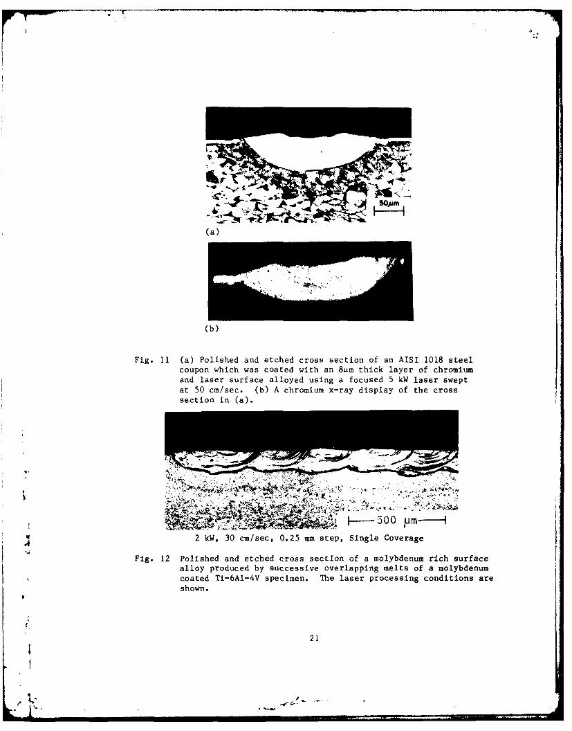
Fig. 11(a) shows the cross section of a- low carbon steel specimen fromwhich a chromium steel surface alloy was made. In this case, the AISI 1018steel was first coated with an 8sim thick layer of chromium. A focused, 5kW,C02 laser beam was swept across the surface at 50 cm/sec to melt the coatingalong with a portion of the substrate. The degree to which the componentsare mixed is illustrated in the chromium x-ray display of Fig. 11(b) whichshows that chromium was dispersed throughout the depth of the melt.
A larger surface may be processed by using successive passes, each oneof which overlaps with the previous pass. This process is illustrated inFig. 12 where a Ti-6A1-4V surface was alloyed with molybdenum. After thissingle set of passes, there remains some variation in composition within themelts as indicated by the large dark arcs that result from the etching. Byreprocessing the surface alloy of Fig. 11 using identical conditions, asubstantially uniform composition is obtained. The result is shown in Fig.
4 13 where the molybdenum addition has produced a single phase surface alloy.
The electrochemical behavior of chromium steel surface alloys describedal~ove (Fig. 12) also have been reported3 6 for three different conditions inde-aerated O.1m Na2 SO4 - Each sample was immersed for 30 minutes and then
20
rwJ.
(a)
(b)
Fig. 11 (a) Polished and etched cross section of an AISI 1018 steelcoupon which was coated with an 8mm thick layer of chromiumand laser surface alloyed using a focused 5 kW laser sweptat 50 cm/sec. (b) A chromium x-ray display of the crosssection in (a).
6_ -
H-500 P2 kW, 30 cm/sec, 0.25 mm step, Single Coverage
Fig. 12 Polished and etched cross section of a molybdenum rich surfacealloy produced by successive overlapping melts of a molybdenumcoated Ti-6A1-4V specimen. The laser processing conditions areshown.
21
.-e--
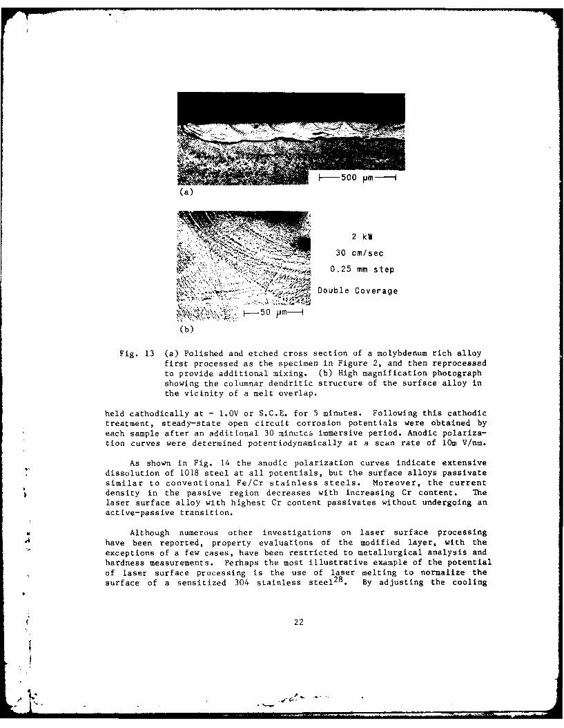
I- 500 pm---
(a)
~&N~ ~2 kW30 cm/sec
. ? 0.25 mm step
" Double Coverage
(b)
Fig. 13 (a) Polished and etched cross section of a molybdenum rich alloyfirst processed as the specimen in Figure 2, and then reprocessedto provide additional mixing. (b) High magnification photographshowing the columnar dendritic structure of the surface alloy inthe vicinity of a melt overlap.
held cathodically at - 1.OV or S.C.E. for 5 minutes. Following this cathodictreatment, steady-state open circuit corrosion potentials were obtained byeach sample after an additional 30 minutcs immersive period. Anodic polariza-tion curves were determined potentiodynamically at a scan rate of 10m V/nm.
As shown in Fig. 14 the anodic polarization curves indicate extensivedissolution of 1018 steel at all potentials, but the surface alloys passivatesimilar to conventional Fe/Cr stainless steels. Moreover, the currentdensity in the passive region decreases with increasing Cr content. Thelaser surface alloy with highest Cr content passivates without undergoing an
active-passive transition.
Although numerous other investigations on laser surface processinghave been reported, property evaluations of the modified layer, with theexceptions of a few cases, have been restricted to metallurgical analysis andhardness measurements. Perhaps the most illustrative example of the potentialof laser surface processing is the use of laser melting to normalize thesurface of a sensitized 304 stainless steel 28 . By adjusting the cooling
22

105r-- 1018 S ELL
4E/10
LASERHO //- ,
2 SURFACE ALLOYS/W 5% Cr-20% Cr
Z 80% Cr --/
Ld 10
o .-- Scan Direction
+1.2 +0.8 4 0 -0.4 -0.8
ELECTRODE POTENTIAL (V vs. S.C.E.)
Fig. 14 Anodic polarization curves for Fe/Cr laser-surface alloys in
de-aerated 0.IM Na2 SO4.
rate to avoid a deleterous carbide phase at the grain boundary, the laserprocessed specimen exhibited a dramatic elimination of intergranular corrosionsusceptibility and a much improved resistance to stress corrosion cracking.
Evidence has also been reported on the improved stress corrosion crack-ing of a-0 titanium alloys by surface melt refinement 37. In this study,rapid laser melting was used to transform the a phase_ to a less SCC suscep-tible martensitic phase. Test of the laser melted titanium specimens,however, showed that the residual stresses arising from incomplete coveragepromoted stress corrosion cracking. In general, the effects of residualstresses on the cracking behavior appears to be an unresolved issue for laserprocessed surfaces of high strength alloys.
Metallurgical analysis of rapid laser surface melting and alloying of avariety of alloys, Zircoloy 38, martensitic and tool steels 3 9, and lowcarbon steel 4 0 show promise to improve their crack tolerance behavioralthough no crack tolerance tests were reported. This situation is incontrast to ion implantation studies where improved fatigue performance is
.4 usually presented without collative metallurgical examination.
There are several possible disadvantages to laser surface alloying.There is a certain amount of roughness introduced by the melting process andalthough conditions can be chosen to minimize the roughness, any application
23
L: , --i '-
must either be tolerant of the roughness or the surface must be refinishedafter laser processing 3 5 . A very strong crystallographic texture can beintroduced by the solidificat-on process as a result of the faster growth ofgrains having low Miller index planes oriented in the direction of thetemperature gradient 36 . The change in texture is most pronounced with finegrained materials where favorably oriented grains will be closer together andso will more quickly squeeze out less favorably oriented grains. The mostsignificant drawback of laser surface processing is the residual stressintroduced by the rapid, localized heating of the surface. These residualstresses limit the number of materials that can be processed since many willcrack as a result of tie orocessing. Short of this, the residual stresses cancause warpage of a workpiece, require a stress relieving heat treatment, orother stress modifying treatment, such as peening. In any application thesedrawbacks will have to be weighed against the advantages described previously,
Two major technical issues remain to be addressed. The first is deter-mining the best method of introducing the alloying elements. This can beaccompLished either by the addition of a powder mixture, an alloy powder, orwire, dirctlv to the melt, or by coating the specimen using traditionaltechniques before the laser 1rocessing. The second issue is the developmentof techniqiies for quality assurance which will insure the batch to batchreproducihiitv () the product.
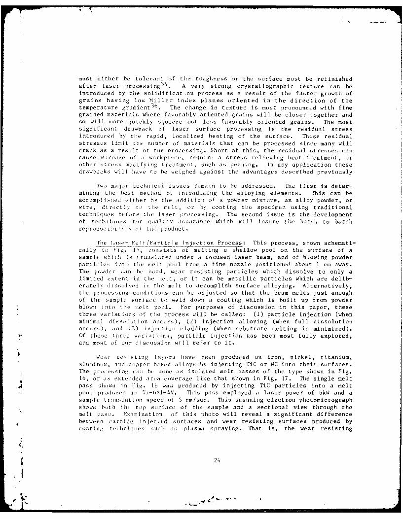
The Laser Melt/Particle Injection Process: This process, shown schemati-cally in Fig. 15, 'onsists of melting a shallow pool on the surface of asample which is tranilated under a focused laser beam, and of blowing powderparticles into the melt pool from a fine nozzle positioned about 1 cm away.The pcsder can ht, hard, wear resisting particles which dissolve to only alimited extent in the melt, or it can be metallic particles which are delib-erately dtssolved in the melt to accomplish surface alloying. Alternatively,the processing conditions can be adjusted so that the beam melts just enoughof the sample surlace to weld down a coating which is built up from powderblown into the mlelt pool. For purposes of discussion in this paper, thesethree variations of the process will be called: (1) particle injection (whenminimal dissolution occurs), (2) injection alloying (when full dissolutionoccurs), and (3) injection cladding (when substrate melting is minimized).Of these three variations, particle injection has been most fully explored,and most of our discussion will refer to it.
Wear resisting layers have been produced on iron, nickel, titanium,aluminum, -ind copper based alloys by injecting TiC or WC into their surfaces.The processing can be done as isolated melt passes of the type shown in Fig.16, or as extended area coverage like that shown in Fig. 17. The single meltpass shown in Fig. 16 was produced by injecting TiC particles into a meltpool produced in Ti-6AI-4V. This pass employed a laser power of 6kW and asample translation speed of 5 cm/sec. This scanning electron photomicrographshows both the top surface of the sample and a sectional view through themelt pass. Examination of this photo will reveal a significant differencebetween carbide injected surtfaces and wear resisting surfaces produced bycoating t(. hniques such as plasma spraying. That is, the wear resisting
24
LASER SEAM
POWDER/INJECTION
NOZZLE/
INJECTED/ SOLID
LI1Q0)U I SUBSTRATE
POOL MOTION
Fig. 15 Injection of particles into a melt zone established by ahigh power laser beam.
Fig. 16 Sectional view of Ti-6A1-4V sample injected with TiC particles.
25
3 mmr
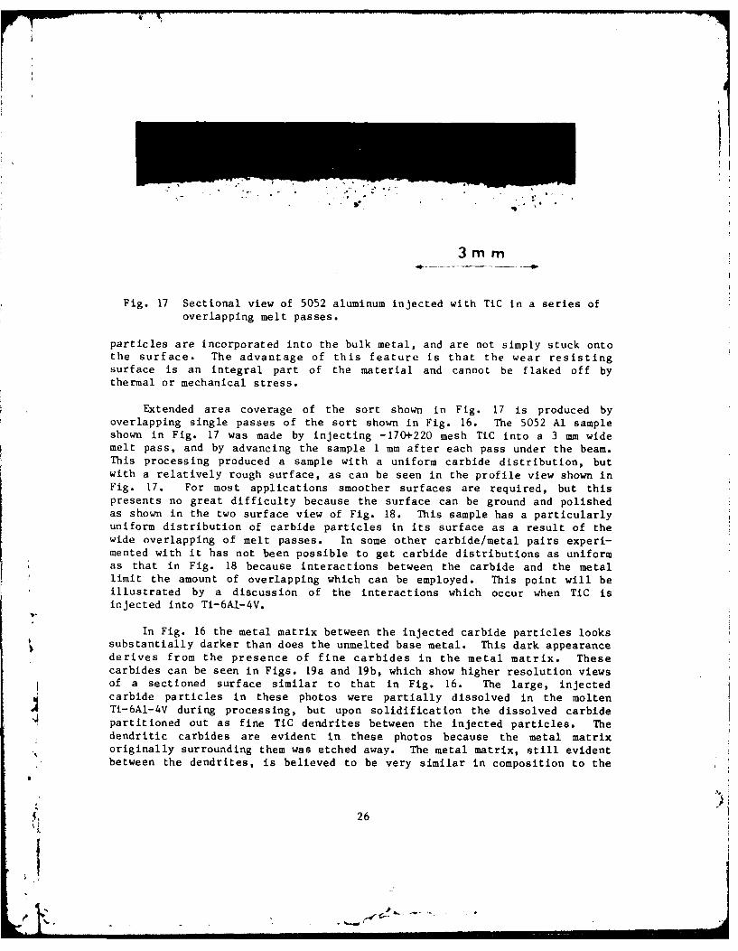
Fig. 17 Sectional view of 5052 aluminum injected with TiC in a series ofoverlapping melt passes.
particles are incorporated into the bulk metal, and are not simply stuck ontothe surface. The advantage of this feature is that the wear resistingsurface is an integral part of the material and cannot be flaked off bythermal or mechanical stress.
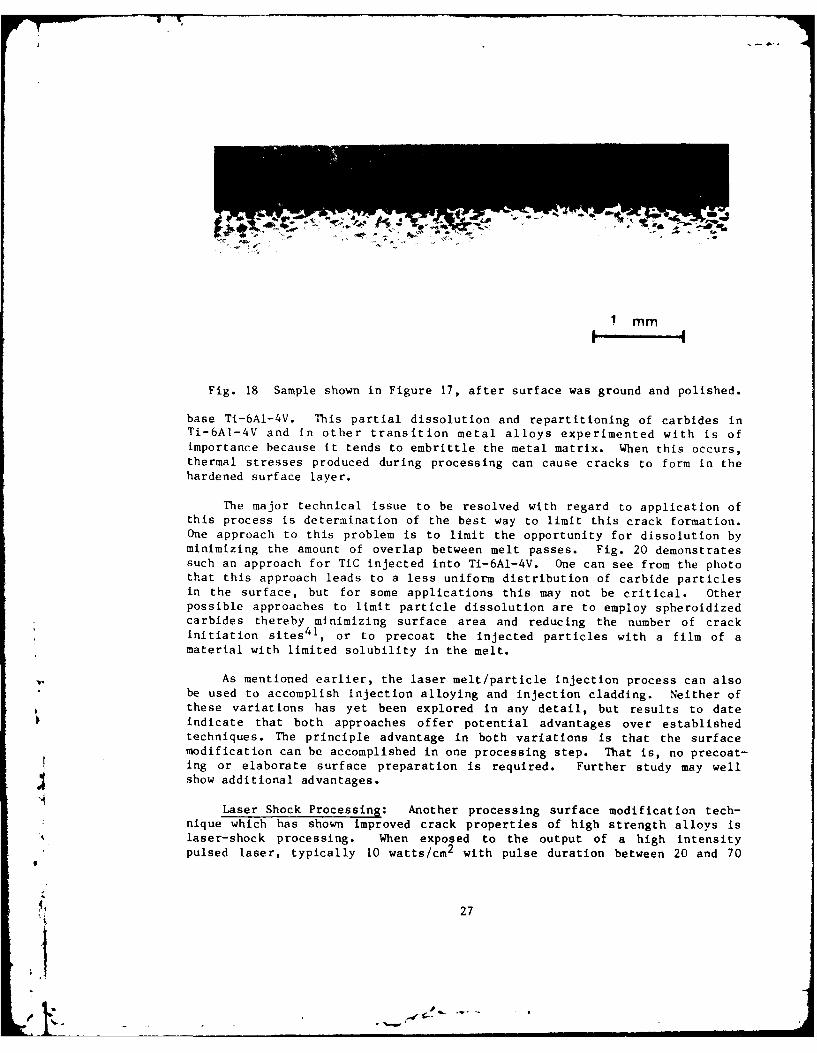
Extended area coverage of the sort shown in Fig. 17 is produced byoverlapping single passes of the sort shown in Fig. 16. The 5052 Al sampleshown in Fig. 17 was made by injecting -170+220 mesh TiC into a 3 mm, widemelt pass, and by advancing the sample 1 mm after each pass under the beam.This processing produced a sample with a uniform carbide distribution, butwith a relatively rough surface, as can be seen in the profile view shown inFig. 17. For most applications smoother surfaces are required, but thispresents no great difficulty because the surface can be ground and polishedas shown in the two surface view of Fig. 18. This sample has a particularlyuniform distribution of carbide particles in its surface as a result of thewide overlapping of melt passes. In some other carbide/metal pairs experi-mented with it has not been possible to get carbide distributions as uniformas that in Fig. 18 because interactions between the carbide and the metallimit the amount of overlapping which can be employed. This point will beillustrated by a discussion of the interactions which occur when TiC isinjected into Ti-6A,1-4V.
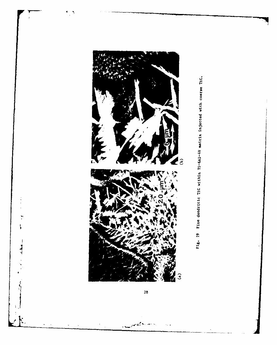
In Fig. 16 the metal matrix between the injected carbide particles lookssubstantially darker than does the unmelted base metal. This dark appearancederives from the presence of fine carbides in the metal matrix. Thesecarbides can be seen in Figs. 19a and 19b, which show higher resolution viewsof a sectioned surface similar to that in Fig. 16. The large, injectedcarbide particles in these photos were partially dissolved in the moltenTi-6A1-4V during processing, but upon solidification the dissolved carbidepartitioned out as fine TiC dendrites between the injected particles. Thedendritic carbides are evident in these photos because the metal matrixoriginally surrounding them was etched away. The metal matrix, still evidentbetween the dendrites, is believed to be very similar in composition to the
26
1 mm
Fig. 18 Sample shown in Figure 17, after surface was ground and polished.
base Ti-6AI-4V. This partial dissolution and repartitioning of carbides inTi-6A1-4V and in other transition metal alloys experimented with is ofimportance because it tends to embrittle the metal matrix. When this occurs,thermal stresses produced during processing can cause cracks to form in thehardened surface layer.
The major technical issue to be resolved with regard to application ofthis process is determination of the best way to limit this crack formation.One approach to this problem is to limit the opportunity for dissolution byminimizing the amount of overlap between melt passes. Fig. 20 demonstratessuch an approach for TiC injected into Ti-6A1-4V. One can see from the photothat this approach leads to a less uniform distribution of carbide particlesin the surface, but for some applications this may not be critical. Otherpossible approaches to limit particle dissolution are to employ spheroidizedcarbides thereby minimizing surface area and reducing the number of crackinitiation sites 41 , or to precoat the injected particles with a film of amaterial with limited solubility in the melt.
As mentioned earlier, the laser melt/particle injection process can alsobe used to accomplish injection alloying and injection cladding. Neither ofthese variations has yet been explored in any detail, but results to dateindicate that both approaches offer potential advantages over establishedtechniques. The principle advantage in both variations is that the surfacemodification can be accomplished in one processing step. That is, no precoat-ing or elaborate surface preparation is required. Further study may wellshow additional advantages.
Laser Shock Processing: Another processing surface modification tech-nique which has shown improved crack properties of high strength alloys islaser-shock processing. When exposed to the output of a high intensitypulsed laser, typically 10 watts/cm 2 with pulse duration between 20 and 70
27
I'1 .1
• AJ
)~I~p.... '-
C, *
,,,y, o
!1 '1 I.
d 4! ' 'JJ
29-I o!4

2 mm
Fig. 20 Sectional view of Ti-Al-4V sample injected with TiC. Surfacewas ground flat after injection processing.
macroseconds, stress waves are induced into an irradiated material42 . Thisreaction is generated by the extremely rapid vaporization of the irradiatedmaterial and the subsequent expansion of the heated vapor against the targetsurface. In comparison to the magnitude and velocity to conventional flyerplate generated shock waves, laser induced stress wave should be classifiedas weak shock, typically reaching peak pressures of less than a kilobar.Methods of amplifying laser induced stress to high pressures are achieved byplacing opaque and transparent overlays on the test piece. The benefits oflaser shock hardening relative to other methods of shock hardening or conven-tional work hardening is not clear, although the laser technique has beenshown to be one of the most useful methods for treating localized or inacces-sible areas.
Laser-shock processing has been shown 43 to increase the yield strengthand to a lesser extent the ultimate strength of age-hardenable aluminumweldments, 5086-1132 and 6061-T6, and of solid solution strengthened aluminumalloys, 7075-T6 and 2024-T35. The fatigue crack initiation resistance, thefatigue crack growth resistance, and the data scatter have been shown to besignificantly improved by laser-shock processing3 2 . Using this technique,data has also been reported on an increased fretting fatigue resistance of7075-T6 fastener joints 4 4 . The above results suggest the use of lasershock processing to improve the strength and fatigue properties of criticalareas of structures, such as welded joints and highly stressed regions.
29

SUMMARY STATEMENT
The intent of this paper has been to present representative examples ofthe requirements, issues, and opportunities facing the Naval structuralmaterials community over the next several decades. In order to keep thepaper to a tractable length, many equally important topics, including thoseassociated with strategic missile, space systems, and other marine structures,were omitted reluctantly and any priority of effort should not be inferred byomission herein.
ACKNOWLEDGEMENTS
The authors wish to acknowledge the helpful discussion and writtenimputs to this paper from their colleagues at the Naval Research Laboratory,including Dale Meyn, Ron Vardiman, Peter Moore, Bhakta Rath, Jim Hirvonen,Jack Ayers, Ed McCafferty, George Yoder, Tom Crooker, and Bob Jones.
30
II4I
REF ERENCES
1. S. Lambardo, S. L. Moskowitz, S. A. Schnure, "Experimental Results of aTranspiration-Cooled Turbine Operated in an Engine for 150 hours and2500 F Turbine Inlet Temperature," 67-G7-29 ASME Turbine Conference,Houston, Texas, 1967.
2. J. W. Fairbanks, "The FT9 Marine Gas Engine Development Program" NavalEngineers Journal, December 1975, pp. 79-96.
3. R. J. Bratton, A. W. Holden, "Ceramics in Gas Turbines for ElectricPower Generator," in Ceramics for High Performance Application (J. J.Burke, A. E. Gorum and R.N. Katz, eds.) Proceedings of the Second ArmyMaterials Technology Conference, Hyannis, Massachusetts, 1973.
4. L. R. Jones, A Summary and Review of NAVSEA Funded Low Power HotCorrosion Studies, NRL Memo Rept. 4072, (1979).
5. C. T. Fujii, "Stress Corrosion Cracking Properties of 17-4PH Steel" inStress Corrosion-New Approaches, ASTM STP-610, American Society forTesting and Materials, 1976, pp. 213-255.
6. L. R. Hettche and B. B. Rath, Fabrication and Processing Technologyfor Improved Crack Tolerant Properties of Structural Alloys: CurrentR&D Activities and Emergent Research Opportunities NRL Memo Rept. 4148,(1980).
7. G. R. Yoder, L. A. Cooley and T. W. Crooker, "Observations on the Gen-erality of the Grain Size Effect on Fatigue Crack Growth in Alpha PlumBeta Titanium Alloys, TITANIUM '80, H. Kimura and 0. Izumi (eds.)Vol. 3, The Metallurgical Society of AIME, Warrendale, Pa. 1981,pp. 1865-1874.
8. G. Dearnaley, J. H. Freeman, R. S. Nelson, and J. Stephen, "Ion Im-plantation", North Holland, Amsterdam (1973).
9. C. M. Preece and J. K. Hirvonen (eds.), Ion Implantation Metallurgy,Conference Proceeding The Metallurgical Society of ASME, Warrendale,Pa. (1979).
10. J. K. Hirvonen, "Ion Implantation," (Herb Herman, ed.), Treatise onMaterials Science and Technology, Vol. 18, p. 502, Academic Press,(1980)
11. N. E. W, Hartey, Tribological Effects in Ion Implanted Metals, in"Application of Ion Beams to Materials", G. Carter, J. S. Colligon,and W. A. Grant, ed., Inst. of Physics Conf., Ser. No. 28 (1976).
31

12. M. W. Thompson, Applications of Ion Implantation Outside the Semi-conductor Area, in Proc. Europ. Conf. on Ion Implantation, Peregrinus(1970).
13. W. W. Hu, C. R. Clayton, and J. K. Hirvonen, Fatigue-Life Enhancementby Ion Implantation, Scripta Met. 12, (1978).
14. J. K. Hirvonen, C. A. Carosella, R. A. Kant, I. Singer, R. G. Vardiman,and B. B. Rath, Thin Solid Films 63, 5 (1979); and R. G. Vardiman andR. A. Kant, (to be published).
15. D. F. Neal and P. A. Blenkinsop, Internal Fatigue Origins in TitaniumAlloys, Acta Metall. 24:59 (1979); J. Quippen, R. Bhowal, D. Eylon,and Q. J. McEvily, "Fatigue Mechanism ed., J. T. Fong (ASTM-STP 675,1979), p. 47.
16. B. D. Sartwell, A. B. Campbell and P. B. Needham, Proccedings FifthInternational Conference on Ion Implantation in Semiconductors andOther Materials, Boulder, CO, August 1976, edited by F. Chernow, J. A.Borders and D. Brice (Plenum, New York, 1977).
17. B. S. Covino Jr., P. B. Needham, Jr., and G. R. Conner, Anodic Polari-zation Behavior of Fe-Ni Alloys Fabricated by Ion Implantation, J.Electrochem Soc. 125(3), 370 (1978).
18. Y. K. Wang, G. R. Clayton, G. K. Hubler, W. N. Luche, and J. K.Hirvonen, Application of Ion Implantation for the Improvement ofLocalized Corrosion Resistance of M50 Bearing Steel. Thin Solid Films63 (1979), 11-18.
19. N. E. W. Hartley, Ion Implantation Case Studies, Proc. Conf. SurfaceTreatments for Protection, (London, 1978).
20. J. E. Antill, M. J. Bennett, G. Dearnaley, F. H. Fern, P. D. Goode,and J. F. Turner, Proc. Third International on Ion Implantation inSemiconductors and Other Materials, IBM, Yorktown Heights, 1972 editedby B. L. Crowder (Plenum, New Yor, 1973).
21. U. Bernalai et al., as referenced by G. Dearnaley, "Ion Implantation ofEngineering Components" Proc. Welding Institute Meeting, London, Feb.1978.
22. R. A. Kant, J. K. Hirvonen, A. R Knudson, J. S. Wallam, Surface Harden-ing of Beryllium by Ion Implantation Thin Solid Films, 63 (1979) 27-30.
23. Robert N. Bolster and Irvin L. Singer, "Surface Hardness and AbrasiveWear Resistance of Ion-Implanted Steels," ASME/ASLE Lubrication Confer-ence, Paper #80-LC-8B-3, San Francisco, Cal. (1980).
32
24. N. E. W. Hartley, "Tribological Effects in Ion Implanted Metals," inApplications of Ion Beams to Materials, edited by G. Carter, J. S.Colligen and W. A. Grant (Institute of Physics, L~adon, 1976), p. 210.
25. I. L. Singer, J. S. Murday, H. Ravner, J. K. Hirvonen, N. L. Jarvis,"New Opportunities in Tribology," Naval Research Reviews, Vol. 32,No. 4, pp. 4-17 (1980).
26. F. D. Seaman and D. S. Gnanamuthu, "Using the Industrial Laser toSurface Harden and Alloy", Metal Progress, Vol. 108, No. 3, p. 67(1975).
27. E. M Breinan, B. H. Kear, and C. M. Banas, "Processing Materials withLasers", Physics Today, Vol. 29, No. 11, P. 44 (1976).
28. T. R. Anthony and H. E. Cline, "Surface Normalization of SensitizedStainless Steel by Laser Surface Melting," J. Applied Physics, Vol. 49No. 3, March 1978, p. 1248.
29. D. S. Gnanamuthu, "Cladding", United States Patent No. Re. 29815,24 (October 1978).
30. G. C. Irons, "Laser Fusing of Flame Sprayed Coatings", Welding Jou nal,Vol. 57, No. 12, p. 29 (1978).
31. J. D. Ayers and R. J. Schaefer, "Consolidation of Plasma-Sprayed Coat-ings by Laser Remelting", Proceedings of the Society of Photo-OpticalInstrumentation Engineers, Vol. 198, p. 57 (1980).
32. A. H. Clauer, B. P. Fairand, "Interaction of Laser Induced Stress Waveswith Metals", E. A. Metzbower, ed., Am. Soc. for Metals, Washington, D.C.(1979).
33. R. J. Schaefer, T. R. Tucker, and J. D. Ayers, "Laser Surface Meltingwith Carbide Particle Injection, "Laser and Electron Beam Processing ofMaterials, Academic Press, N.Y., New York, p. 749 (1980).
34. J. D. Ayers, T. R. Tucker, and R. J. Schaefer, "Wear Resisting Surfacesby Carbide Particle Injection", Proceeding of Reston, Virginia, inpress (1980).
35. P. G. Moore and L. S. Weinman, in Laser Application in Material Pro-cessing, edited by John F. Ready (Society of Photo-Optical Instrumen-tation Engineers, Bellinham, WA,) P. 120-125 (1980).
36. P. G. Moore and E. McCafferty, Passivation of Fe/Cr Alloys Prepared byLaser Surface Alloying, submitted J. of the Electrochemical Society.
4I 33

37. P. Moore, C. Kim, and L. S. Weiman, Processing and Properties of LaserSurface Melted Titanium Alloys, in Appl. of Lasers in Mat'l. Process-ing, E. A. Metzbower, ed., Am. Soc. for Metals, Washington, D. C.(1979).
38. D. B. Snow and E. M. Breinan, Microstructural Transformations by theLaserglaze Process in Zircaloy-4 Sheet, in Appl. of Lasers in Mat'l.Processing, E. A. Metzbower, ed., Am. Soc. for Metals, Washington, D.C.(1979).
39. P. R. Strutt, H. Norvotney, M. Tuli and B. H., Kear, Laser SurfaceMelting of High Speed Tool Steels, Mat'ls. Sci. Eng. 36 (1978).
40. Michael Yessik, R. P. Scherer, "Practical Guidelines for Laser SurfaceHardening" in Laser in Modern Industry, Ed. John F. Ready, Society ofManufacturing Engineers, Dearborn, Michigan (1979).
41. J. D. Ayers and T. R. Tucker, "Particulate TiC Hardened Steel Sur-faces by Laser Melt Injection," Thin Solid Films, Vol. 73, No. 1,
pp. 201-207 (1980).
42. L. R. Hettche, T. R. Tucker, J. T. Schriempf, and R. L. Stegman,"Mechanical Response and Thermal Coupling of Metallic Targets toHigh Intensity 1.06 Laser Radiation," J. App. Phys., Vol. 44, No. 9,Sep 1973, pp. 4079-4085.
43. A. H. Clauer, B. P. Fairand, and B. A. Wilcox, "Laser Shock Hardeningof Weld Zones in Aluminum Alloys," Met. Trans. Vol. A 8A, 187, (1977).
44. W. F. Bates, Jr., 'Laser Shock Processing of Aluminum Alloys," E. A.Metzbower, ed., Am. Soc. for Metals, Washington, D. C. (1979).
a
34
e- ° I .

~I


