32
GEN.0000000005452 Rev A © 2017 SRAM, LLC S-900 Aero HRD Lever / Caliper / Hose Replacement service manual

GEN.0000000005452 Rev A © 2017 SRAM, LLC
S-900 Aero HRDLever / Caliper /Hose Replacement
s e r v i c em a n u a l
SRAM® LLC WARRANTY
EXTENT OF LIMITED WARRANTYExcept as otherwise set forth herein, SRAM warrants its products to be free from defects in materials or workmanship for a period of two years after original purchase. This warranty only applies to the original owner and is not transferable. Claims under this warranty must be made through the retailer where the bicycle or the SRAM component was purchased. Original proof of purchase is required. Except as described herein, SRAM makes no other warranties, guaranties, or representations of any type (express or implied), and all warranties (including any implied warranties of reasonable care, merchantibility, or fitness for a particular purpose) are hereby disclaimed.
LOCAL LAWThis warranty statement gives the customer specific legal rights. The customer may also have other rights which vary from state to state (USA), from province to province (Canada), and from country to country elsewhere in the world.
To the extent that this warranty statement is inconsistent with the local law, this warranty shall be deemed modified to be consistent with such law, under such local law, certain disclaimers and limitations of this warranty statement may apply to the customer. For example, some states in the United States of America, as well as some governments outside of the United States (including provinces in Canada) may:
a. Preclude the disclaimers and limitations of this warranty statement from limiting the statutory rights of the consumer (e.g. United Kingdom).
b. Otherwise restrict the ability of a manufacturer to enforce such disclaimers or limitations.
For Australian customers:This SRAM limited warranty is provided in Australia by SRAM LLC, 1000 W. Fulton Market, 4th Floor, Chicago, IL, 60607, USA. To make a warranty claim please contact the retailer from whom you purchased this SRAM product. Alternatively, you may make a claim by contacting SRAM Australia, 6 Marco Court, Rowville 3178, Australia. For valid claims SRAM will, at its option, either repair or replace your SRAM product. Any expenses incurred in making the warranty claim are your responsibility. The benefits given by this warranty are additional to other rights and remedies that you may have under laws relating to our products. Our goods come with guarantees that cannot be excluded under the Australian Consumer Law. You are entitled to a replacement or refund for a major failure and for compensation for any other reasonably foreseeable loss or damage. You are also entitled to have the goods repaired or replaced if the goods fail to be of acceptable quality and the failure does not amount to a major failure.
LIMITATIONS OF LIABILITYTo the extent allowed by local law, except for the obligations specifically set forth in this warranty statement, in no event shall SRAM or its third party suppliers be liable for direct, indirect, special, incidental, or consequential damages.
LIMITATIONS OF WARRANTYThis warranty does not apply to products that have been incorrectly installed and/or adjusted according to the respective SRAM user manual. The SRAM user manuals can be found online at sram.com, rockshox.com, avidbike.com, truvativ.com, or zipp.com.
This warranty does not apply to damage to the product caused by a crash, impact, abuse of the product, non-compliance with manufacturers specifications of usage or any other circumstances in which the product has been subjected to forces or loads beyond its design.
This warranty does not apply when the product has been modified, including, but not limited to any attempt to open or repair any electronic and electronic related components, including the motor, controller, battery packs, wiring harnesses, switches, and chargers.
This warranty does not apply when the serial number or production code has been deliberately altered, defaced or removed.
This warranty does not apply to normal wear and tear. Wear and tear parts are subject to damage as a result of normal use, failure to service according to SRAM recommendations and/or riding or installation in conditions or applications other than recommended.
Wear and tear parts are identified as:
Dust sealsBushingsAir sealing o-ringsGlide ringsRubber moving partsFoam ringsRear shock mounting
hardware and main sealsUpper tubes (stanchions)
Stripped threads/bolts (aluminium, titanium, magnesium or steel)
Brake sleevesBrake padsChainsSprocketsCassettesShifter and brake cables
(inner and outer)
Handlebar gripsShifter gripsJockey wheelsDisc brake rotorsWheel braking surfacesBottomout padsBearingsBearing racesPawls
Transmission gearsSpokesFree hubsAero bar padsCorrosionToolsMotorsBatteries
Notwithstanding anything else set forth herein, the battery pack and charger warranty does not include damage from power surges, use of improper charger, improper maintenance, or such other misuse.
This warranty shall not cover damages caused by the use of parts of different manufacturers.
This warranty shall not cover damages caused by the use of parts that are not compatible, suitable and/or authorised by SRAM for use with SRAM components.
This warranty shall not cover damages resulting from commercial (rental) use.

SAFETY FIRST!We care about YOU. Please, always wear your safety glasses
and protective gloves when servicing SRAM® products. Protect yourself! Wear your safety gear!
TABLE OF CONTENTS
SRAM® S-900 AERO HRD BRAKE SYSTEMS ..................................................................................................................................................5SERVICE PROCEDURES .................................................................................................................................................................................................................................5
TROUBLESHOOTING ..........................................................................................................................................................................................7PARTS, TOOLS, AND SUPPLIES ..................................................................................................................................................................................................................7DISC BRAKE PAD ADVANCEMENT PROCEDURE .................................................................................................................................................................................7
LEVER SERVICE .................................................................................................................................................................................................10PARTS, TOOLS AND SUPPLIES ................................................................................................................................................................................................................. 10S-900 AERO LEVER EXPLODED VIEW.................................................................................................................................................................................................... 10LEVER BLADE REMOVAL.............................................................................................................................................................................................................................. 11MASTER PISTON SERVICE .......................................................................................................................................................................................................................... 12LEVER BLADE INSTALLATION ................................................................................................................................................................................................................... 14WEDGE CLAMP SERVICE ............................................................................................................................................................................................................................ 15
CALIPER SERVICE ............................................................................................................................................................................................. 17PARTS, TOOLS, AND SUPPLIES ................................................................................................................................................................................................................ 17CALIPER EXPLODED VIEW ......................................................................................................................................................................................................................... 17CALIPER BRAKE PAD REMOVAL ............................................................................................................................................................................................................... 18CALIPER PISTON REMOVAL ....................................................................................................................................................................................................................... 19CALIPER PISTON INSTALLATION ............................................................................................................................................................................................................ 23
HOSE REPLACEMENT ...................................................................................................................................................................................... 25PARTS, TOOLS, AND SUPPLIES ............................................................................................................................................................................................................... 25HOSE REMOVAL ............................................................................................................................................................................................................................................ 25HOSE INSTALLATION .................................................................................................................................................................................................................................. 28
5SRAM® S-900 Aero HRD Brake Systems
S R A M ® S - 9 0 0 A e r o H R D B r a k e S y s t e m sWe recommend that you have your SRAM S-900 Aero HRD components serviced by a qualified bicycle mechanic. Servicing SRAM components requires knowledge of bicycle mechanics as well as the special tools and lubricants/fluids used for service.
SRAM brake systems need to be serviced periodically to optimize braking function. If brake fluid is leaking from any area of the brake there may be damage or wear and tear to the internal moving parts. If the system has been contaminated with the wrong fluid there may be damage to all rubber and plastic internal parts. If your brake was damaged in a crash, there may be damage to the lever blade, pushrod, and housing assemblies. Inspect and replace these parts to restore proper brake function.
Visit www.sram.com/service for the latest SRAM Spare Parts catalog and technical information. For order information, please contact your local SRAM® distributor or dealer.
For recycling and environmental compliance information, please visit www.sram.com.
Information contained in this publication is subject to change at any time without prior notice. Your product's appearance may differ from the pictures contained in this publication.
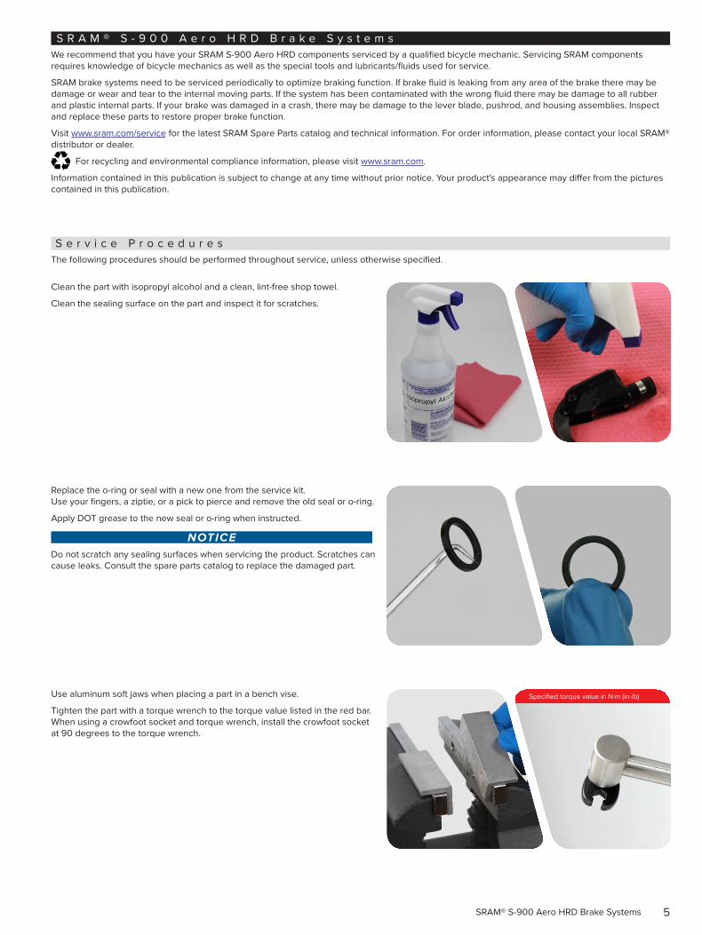
S e r v i c e P r o c e d u r e sThe following procedures should be performed throughout service, unless otherwise specified.
Clean the part with isopropyl alcohol and a clean, lint-free shop towel.
Clean the sealing surface on the part and inspect it for scratches.
Replace the o-ring or seal with a new one from the service kit. Use your fingers, a ziptie, or a pick to pierce and remove the old seal or o-ring.
Apply DOT grease to the new seal or o-ring when instructed.
NOTICEDo not scratch any sealing surfaces when servicing the product. Scratches can cause leaks. Consult the spare parts catalog to replace the damaged part.
Use aluminum soft jaws when placing a part in a bench vise.
Tighten the part with a torque wrench to the torque value listed in the red bar. When using a crowfoot socket and torque wrench, install the crowfoot socket at 90 degrees to the torque wrench.
Specified torque value in N·m (in-lb)
6Service Procedures
SAFETY INSTRUCTIONSFor best results, use only SRAM® High-Performance DOT 5.1 brake fluid. If SRAM brake fluid is not available, only use DOT 5.1 or 4 brake fluid.
Do not use mineral oil or DOT 5 fluid. If the brake system has been contaminated with mineral oil or DOT 5 fluid, the braking system (e.g. the brake lever, caliper, and hose) will need to be replaced.
Use only DOT compatible grease.
Always wear safety glasses and nitrile gloves when working with DOT fluid.
Used DOT fluid should be recycled or disposed of in accordance to local and federal regulations.
Never pour DOT fluid down a sewage or drainage system or into the ground or a body of water.
Do not allow any brake fluid to come in contact with the brake pads. If this occurs, the pads are contaminated and must be replaced.
Place an oil pan on the floor underneath the area where you will be working on the brake.
Servicing your brakes removes all of the brake fluid from the system. You must bleed your brakes after you service the brake caliper. Consult the S-900 Aero HRD User Manual at www.sram.com/service.
NOTICEBefore beginning service, thoroughly clean the exterior of the product to avoid contamination of internal sealing part surfaces.
DOT fluids will damage painted surfaces. If any fluid comes in contact with a painted surface (e.g. your frame) or printing on the brakes, wipe it off immediately and clean it with isopropyl alcohol or water. Damage to painted and/or printed surfaces by DOT fluid is not covered under warranty.
7Troubleshooting
T r o u b l e s h o o t i n g
P a r t s , T o o l s , a n d S u p p l i e sSafety and Protection Supplies
• Apron
• Clean, lint-free shop towels
• Nitrile gloves
• Safety glasses
Bicycle Tools
• Bicycle work stand
• Tire lever
SRAM Tools
• Pad spreader tool
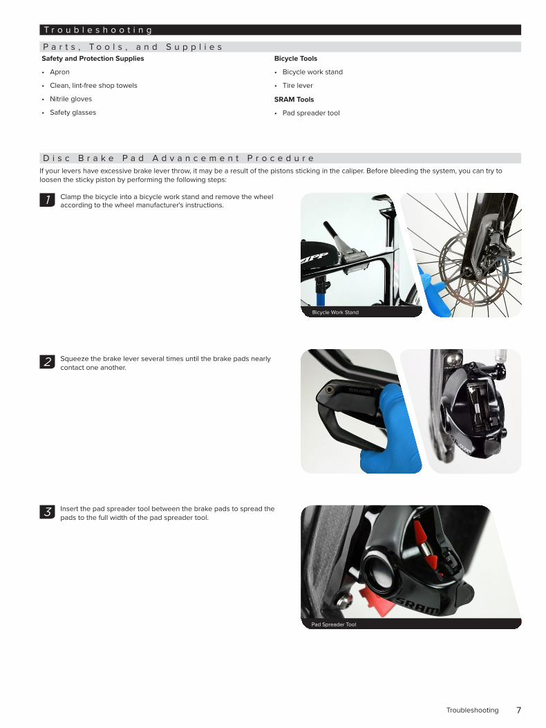
D i s c B r a k e P a d A d v a n c e m e n t P r o c e d u r eIf your levers have excessive brake lever throw, it may be a result of the pistons sticking in the caliper. Before bleeding the system, you can try to loosen the sticky piston by performing the following steps:
Clamp the bicycle into a bicycle work stand and remove the wheel according to the wheel manufacturer's instructions.
Squeeze the brake lever several times until the brake pads nearly contact one another.
Insert the pad spreader tool between the brake pads to spread the pads to the full width of the pad spreader tool.
Bicycle Work Stand
1
2
Pad Spreader Tool 2.7-3.2 N•m (24-28 in-lb) 22 mm
3
8Disc Brake Pad Advancement Procedure
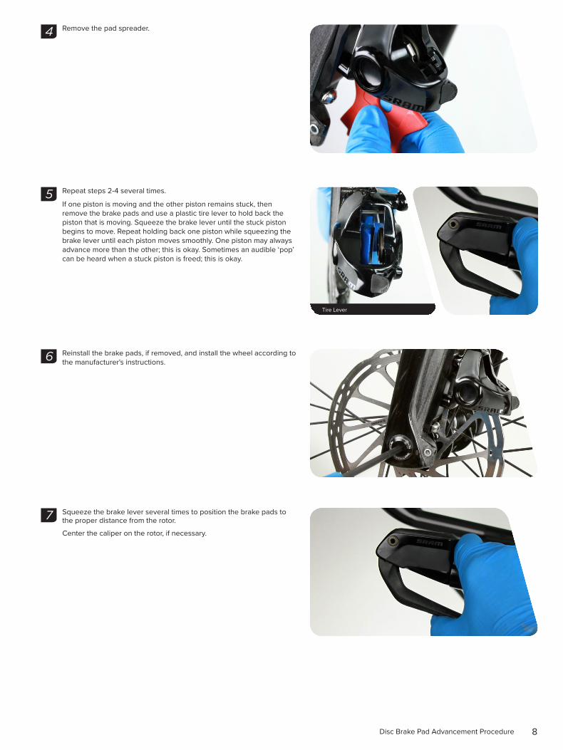
Remove the pad spreader.
Repeat steps 2-4 several times.
If one piston is moving and the other piston remains stuck, then remove the brake pads and use a plastic tire lever to hold back the piston that is moving. Squeeze the brake lever until the stuck piston begins to move. Repeat holding back one piston while squeezing the brake lever until each piston moves smoothly. One piston may always advance more than the other; this is okay. Sometimes an audible ‘pop’ can be heard when a stuck piston is freed; this is okay.
Reinstall the brake pads, if removed, and install the wheel according to the manufacturer's instructions.
Squeeze the brake lever several times to position the brake pads to the proper distance from the rotor.
Center the caliper on the rotor, if necessary.
4
5
Tire Lever
6
7
9Disc Brake Pad Advancement Procedure
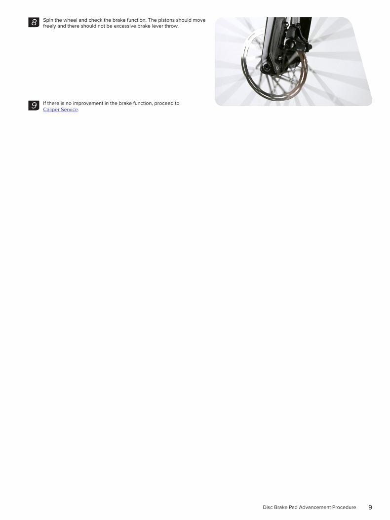
Spin the wheel and check the brake function. The pistons should move freely and there should not be excessive brake lever throw.
If there is no improvement in the brake function, proceed to Caliper Service.
8
9
10Lever Service
L e v e r S e r v i c e
P a r t s , T o o l s a n d S u p p l i e sParts
• SRAM® S-900 Aero HRD Pushrod Kit
Safety and Protection Supplies
• Apron
• Clean, lint-free shop towels
• Nitrile gloves
• Oil pan
• Safety glasses
Lubricants and Fluids
• Isopropyl alcohol
• SRAM DOT 5.1 Fluid If SRAM fluid is not available, only use DOT 5.1 or 4 fluid
• SRAM DOT assembly grease
SRAM Tools
• Monoblock bleed block
Common Tools
• Flat blade screwdriver
• Hex bit sockets: 2.5 mm, 3 mm
• Hex wrenches: 2 mm, 2.5 mm, 3 mm (x2)
• Hydraulic hose cutter
• Needle nose pliers
• Retaining ring pliers
• Torque wrench
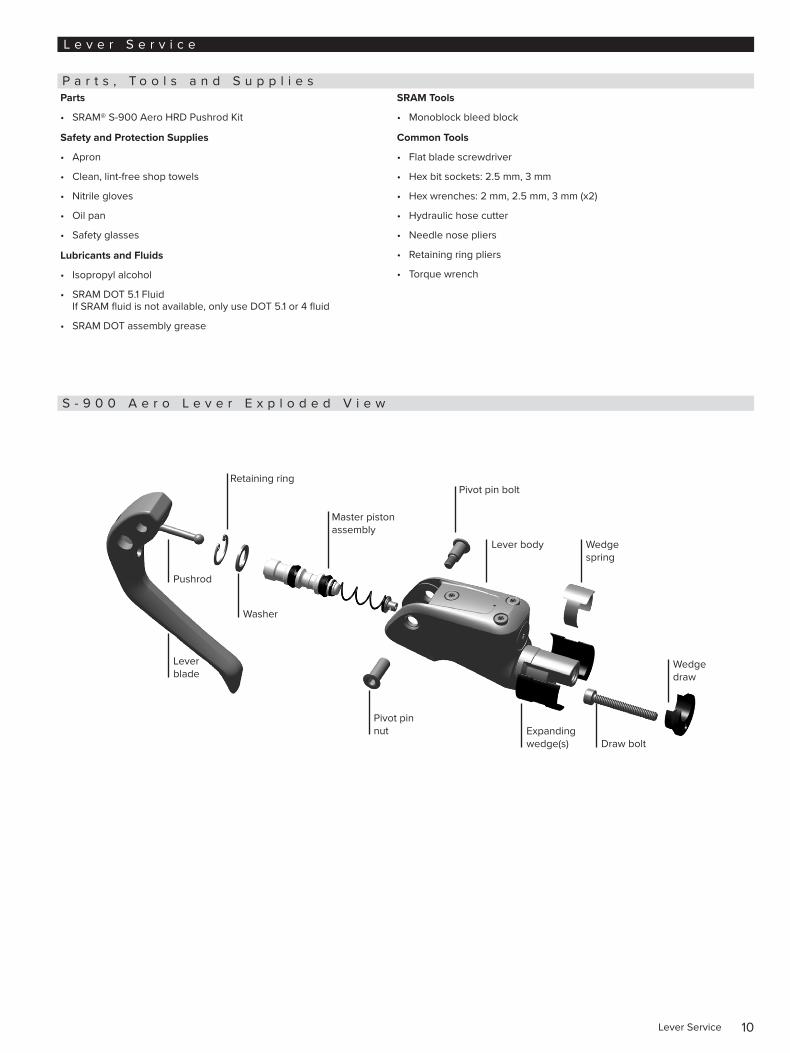
S - 9 0 0 A e r o L e v e r E x p l o d e d V i e w
Pivot pin bolt
Lever body Wedge spring
Wedge draw
Expanding wedge(s)
Pivot pin nut
Washer
Pushrod
Lever blade
Draw bolt
Master piston assembly
Retaining ring
11Lever Blade Removal
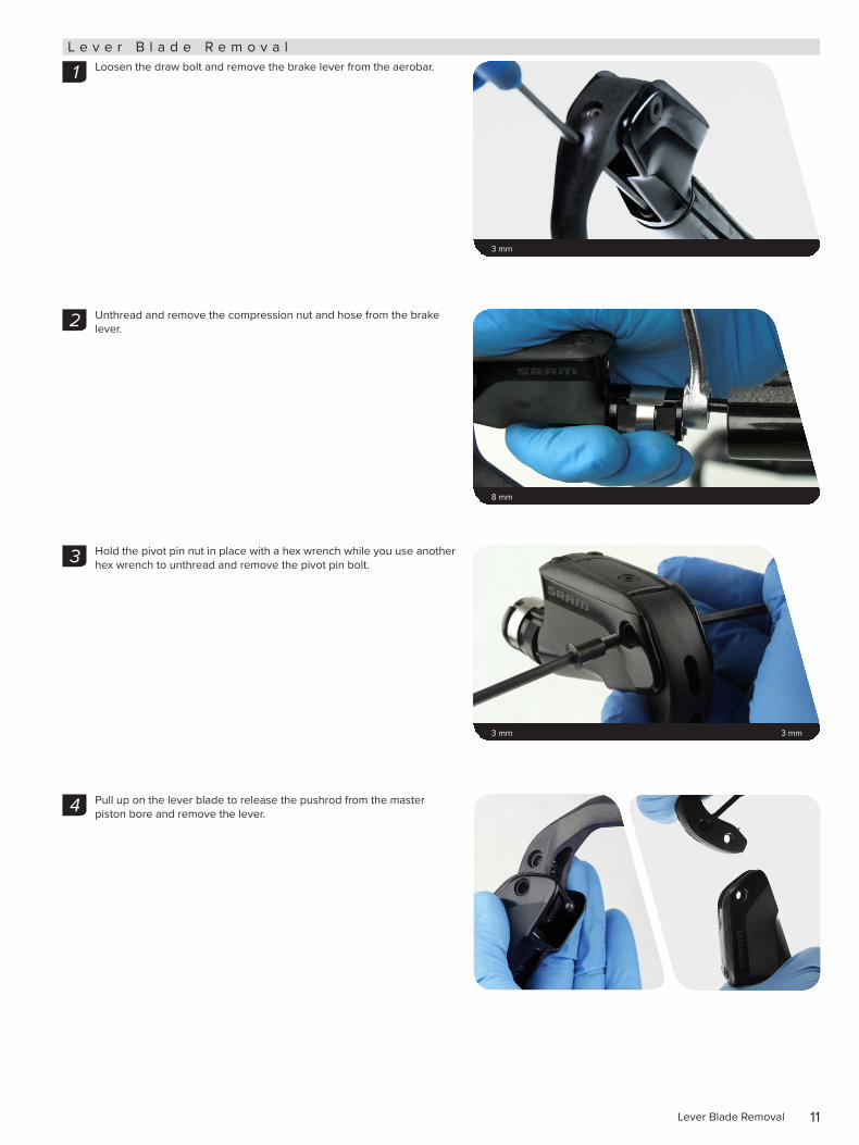
L e v e r B l a d e R e m o v a lLoosen the draw bolt and remove the brake lever from the aerobar.
Unthread and remove the compression nut and hose from the brake lever.
Hold the pivot pin nut in place with a hex wrench while you use another hex wrench to unthread and remove the pivot pin bolt.
Pull up on the lever blade to release the pushrod from the master piston bore and remove the lever.
3 mm
1
8 mm
2
3 mm 3 mm
3
4
12Master Piston Service
M a s t e r P i s t o n S e r v i c e
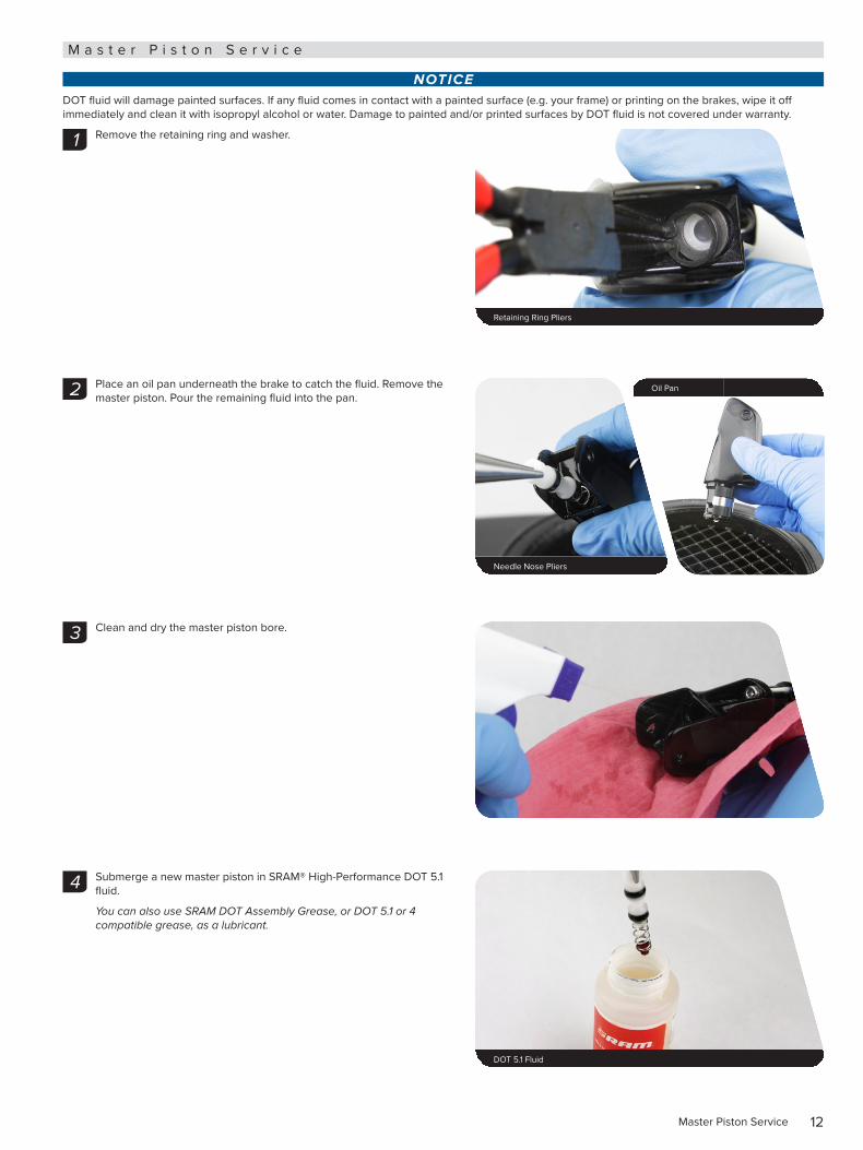
NOTICEDOT fluid will damage painted surfaces. If any fluid comes in contact with a painted surface (e.g. your frame) or printing on the brakes, wipe it off immediately and clean it with isopropyl alcohol or water. Damage to painted and/or printed surfaces by DOT fluid is not covered under warranty.
Remove the retaining ring and washer.
Place an oil pan underneath the brake to catch the fluid. Remove the master piston. Pour the remaining fluid into the pan.
Clean and dry the master piston bore.
Submerge a new master piston in SRAM® High-Performance DOT 5.1 fluid.
You can also use SRAM DOT Assembly Grease, or DOT 5.1 or 4 compatible grease, as a lubricant.
1
Retaining Ring Pliers
Needle Nose Pliers
Oil Pan2
3
4
DOT 5.1 Fluid
13Master Piston Service
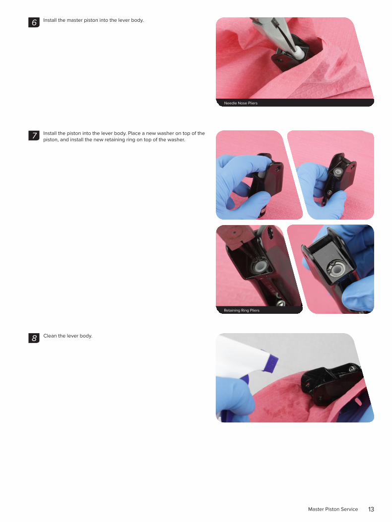
Install the master piston into the lever body.
Install the piston into the lever body. Place a new washer on top of the piston, and install the new retaining ring on top of the washer.
Clean the lever body.
5
Needle Nose Pliers
6
Retaining Ring Pliers
7
8
14Lever Blade Installation
L e v e r B l a d e I n s t a l l a t i o n
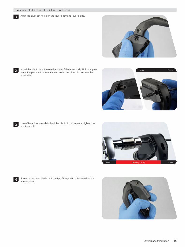
Align the pivot pin holes on the lever body and lever blade.
Install the pivot pin nut into either side of the lever body. Hold the pivot pin nut in place with a wrench, and install the pivot pin bolt into the other side.
Use a 3 mm hex wrench to hold the pivot pin nut in place; tighten the pivot pin bolt.
Squeeze the lever blade until the tip of the pushrod is seated on the master piston.
1
3 mm 3 mm2
3 mm 1.5 N·m (13 in-lb) 3 mm
3
4
15Wedge Clamp Service
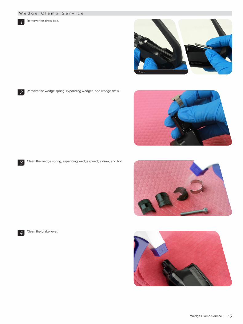
W e d g e C l a m p S e r v i c e
Remove the draw bolt.
Remove the wedge spring, expanding wedges, and wedge draw.
Clean the wedge spring, expanding wedges, wedge draw, and bolt.
Clean the brake lever.
3 mm
1
2
3
4
16Wedge Clamp Service
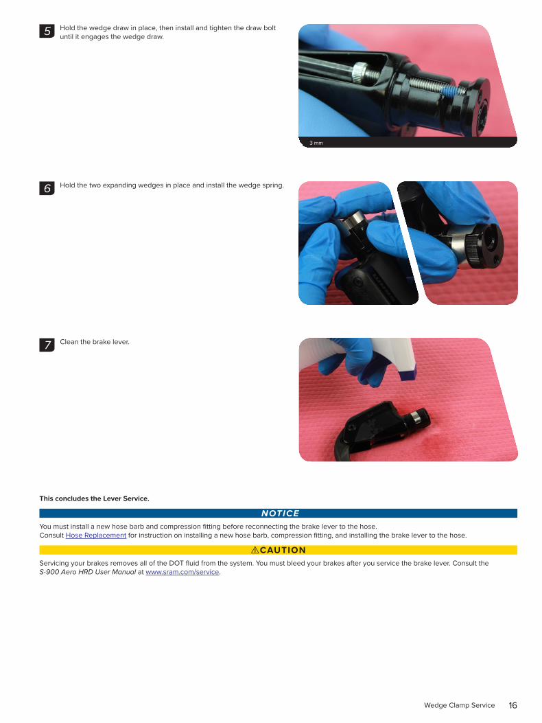
Hold the wedge draw in place, then install and tighten the draw bolt until it engages the wedge draw.
Hold the two expanding wedges in place and install the wedge spring.
Clean the brake lever.
This concludes the Lever Service.
NOTICEYou must install a new hose barb and compression fitting before reconnecting the brake lever to the hose. Consult Hose Replacement for instruction on installing a new hose barb, compression fitting, and installing the brake lever to the hose.
⚠CAUTIONServicing your brakes removes all of the DOT fluid from the system. You must bleed your brakes after you service the brake lever. Consult the S-900 Aero HRD User Manual at www.sram.com/service.
5
3 mm
6
7
17Caliper Service
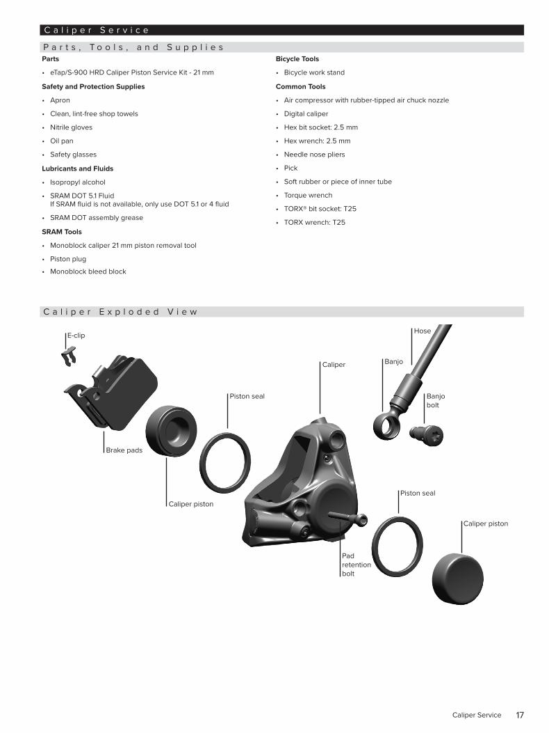
C a l i p e r S e r v i c e
P a r t s , T o o l s , a n d S u p p l i e sParts
• eTap/S-900 HRD Caliper Piston Service Kit - 21 mm
Safety and Protection Supplies
• Apron
• Clean, lint-free shop towels
• Nitrile gloves
• Oil pan
• Safety glasses
Lubricants and Fluids
• Isopropyl alcohol
• SRAM DOT 5.1 Fluid If SRAM fluid is not available, only use DOT 5.1 or 4 fluid
• SRAM DOT assembly grease
SRAM Tools
• Monoblock caliper 21 mm piston removal tool
• Piston plug
• Monoblock bleed block
Bicycle Tools
• Bicycle work stand
Common Tools
• Air compressor with rubber-tipped air chuck nozzle
• Digital caliper
• Hex bit socket: 2.5 mm
• Hex wrench: 2.5 mm
• Needle nose pliers
• Pick
• Soft rubber or piece of inner tube
• Torque wrench
• TORX® bit socket: T25
• TORX wrench: T25
C a l i p e r E x p l o d e d V i e w
E-clip
Caliper piston
Piston seal
Brake pads
Caliper Banjo
Hose
Banjo bolt
Pad retention bolt
Piston seal
Caliper piston
18Caliper Brake Pad Removal
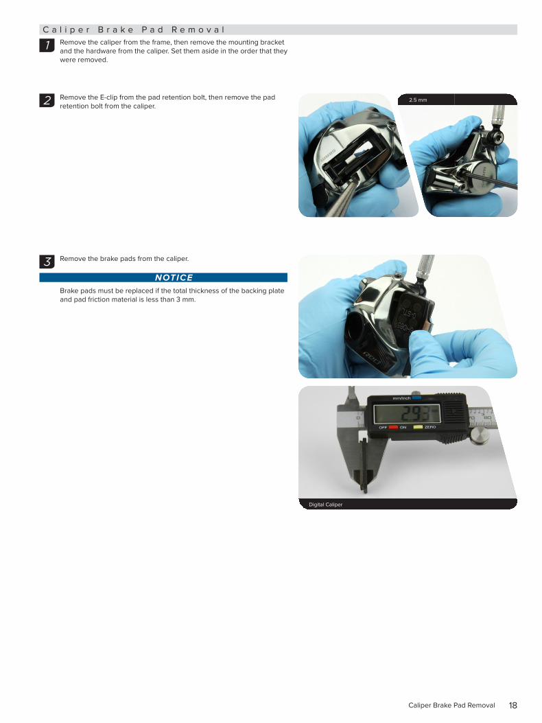
C a l i p e r B r a k e P a d R e m o v a lRemove the caliper from the frame, then remove the mounting bracket and the hardware from the caliper. Set them aside in the order that they were removed.
Remove the E-clip from the pad retention bolt, then remove the pad retention bolt from the caliper.
Remove the brake pads from the caliper.
NOTICEBrake pads must be replaced if the total thickness of the backing plate and pad friction material is less than 3 mm.
1
2.5 mm2
3
Digital Caliper 2.7-3.2 N•m (24-28 in-lb) 22 mm
19Caliper Piston Removal
C a l i p e r P i s t o n R e m o v a l
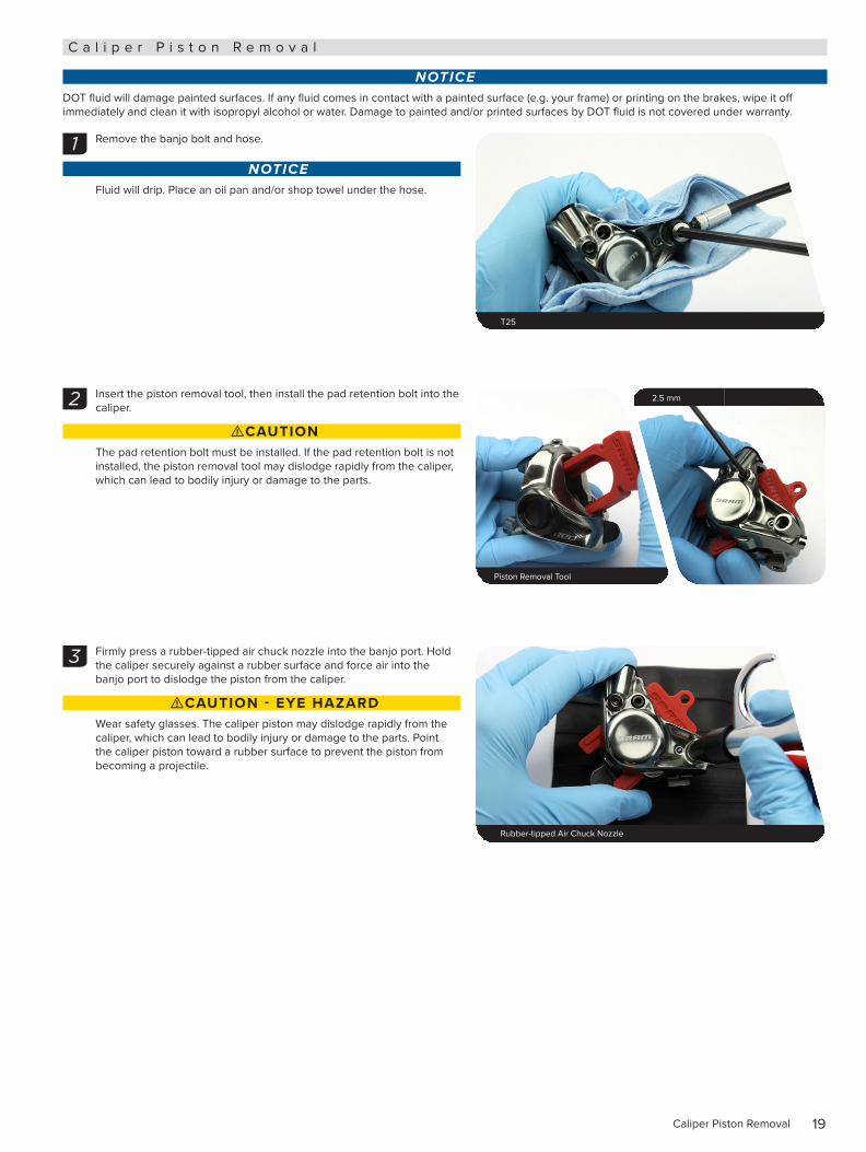
NOTICEDOT fluid will damage painted surfaces. If any fluid comes in contact with a painted surface (e.g. your frame) or printing on the brakes, wipe it off immediately and clean it with isopropyl alcohol or water. Damage to painted and/or printed surfaces by DOT fluid is not covered under warranty.
Remove the banjo bolt and hose.
NOTICEFluid will drip. Place an oil pan and/or shop towel under the hose.
Insert the piston removal tool, then install the pad retention bolt into the caliper.
⚠CAUTION The pad retention bolt must be installed. If the pad retention bolt is not installed, the piston removal tool may dislodge rapidly from the caliper, which can lead to bodily injury or damage to the parts.
Firmly press a rubber-tipped air chuck nozzle into the banjo port. Hold the caliper securely against a rubber surface and force air into the banjo port to dislodge the piston from the caliper.
⚠CAUTION - EYE HAZARDWear safety glasses. The caliper piston may dislodge rapidly from the caliper, which can lead to bodily injury or damage to the parts. Point the caliper piston toward a rubber surface to prevent the piston from becoming a projectile.
1
T25 Rubber-tipped blow gun chuck nozzle 22 mm
2
Piston Removal Tool
2.5 mm
3
Rubber-tipped Air Chuck Nozzle Rubber-tipped blow gun chuck nozzle 22 mm
20Caliper Piston Removal
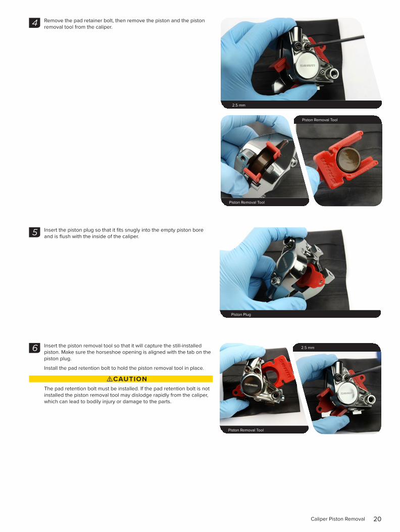
Remove the pad retainer bolt, then remove the piston and the piston removal tool from the caliper.
Insert the piston plug so that it fits snugly into the empty piston bore and is flush with the inside of the caliper.
Insert the piston removal tool so that it will capture the still-installed piston. Make sure the horseshoe opening is aligned with the tab on the piston plug.
Install the pad retention bolt to hold the piston removal tool in place.
⚠CAUTION The pad retention bolt must be installed. If the pad retention bolt is not installed the piston removal tool may dislodge rapidly from the caliper, which can lead to bodily injury or damage to the parts.
Piston Removal Tool
Piston Removal Tool
4
2.5 mm Rubber-tipped blow gun chuck nozzle 22 mm
Piston Plug Rubber-tipped blow gun chuck nozzle 22 mm
5
Piston Removal Tool
2.5 mm6
21Caliper Piston Removal
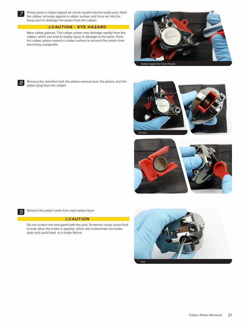
Firmly press a rubber-tipped air chuck nozzle into the banjo port. Hold the caliper securely against a rubber surface and force air into the banjo port to dislodge the piston from the caliper.
⚠CAUTION - EYE HAZARDWear safety glasses. The caliper piston may dislodge rapidly from the caliper, which can lead to bodily injury or damage to the parts. Point the caliper piston toward a rubber surface to prevent the piston from becoming a projectile.
Remove the retention bolt, the piston removal tool, the piston, and the piston plug from the caliper.
Remove the piston seals from each piston bore.
⚠CAUTIONDo not scratch the seal gland with the pick. Scratches could cause fluid to leak when the brake is applied, which will contaminate the brake pads and could lead to a brake failure.
Rubber-tipped Air Chuck Nozzle Rubber-tipped blow gun chuck nozzle 22 mm
7
2.5 mm
8
Pick Rubber-tipped blow gun chuck nozzle 22 mm
9
22Caliper Piston Removal
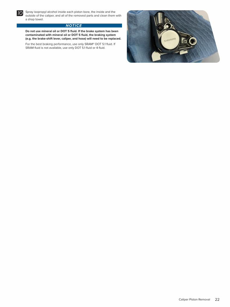
Spray isopropyl alcohol inside each piston bore, the inside and the outside of the caliper, and all of the removed parts and clean them with a shop towel.
NOTICEDo not use mineral oil or DOT 5 fluid. If the brake system has been contaminated with mineral oil or DOT 5 fluid, the braking system (e.g. the brake-shift lever, caliper, and hose) will need to be replaced.
For the best braking performance, use only SRAM® DOT 5.1 fluid. If SRAM fluid is not available, use only DOT 5.1 fluid or 4 fluid.
10
23Caliper Piston Installation
C a l i p e r P i s t o n I n s t a l l a t i o n
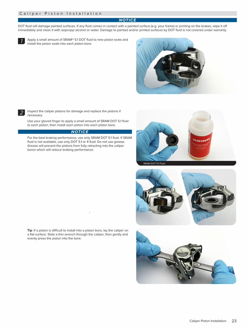
NOTICEDOT fluid will damage painted surfaces. If any fluid comes in contact with a painted surface (e.g. your frame) or printing on the brakes, wipe it off immediately and clean it with isopropyl alcohol or water. Damage to painted and/or printed surfaces by DOT fluid is not covered under warranty.
Apply a small amount of SRAM® 5.1 DOT fluid to new piston seals and install the piston seals into each piston bore.
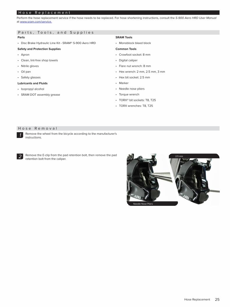
Inspect the caliper pistons for damage and replace the pistons if necessary.
Use your gloved finger to apply a small amount of SRAM DOT 5.1 fluid to each piston, then install each piston into each piston bore.
NOTICEFor the best braking performance, use only SRAM DOT 5.1 fluid. If SRAM fluid is not available, use only DOT 5.1 or 4 fluid. Do not use grease. Grease will prevent the pistons from fully retracting into the caliper bores which will reduce braking performance.
Tip: If a piston is difficult to install into a piston bore, lay the caliper on a flat surface. Slide a thin wrench through the caliper, then gently and evenly press the piston into the bore.
1
2
SRAM DOT 5.1 Fluid Rubber-tipped blow gun chuck nozzle 22 mm

24Caliper Piston Installation
Remove the o-rings from the banjo bolt.
Install the new o-rings and apply a thin layer of grease.
Tighten the banjo bolt with the banjo boot at the desired angle.
Insert the Monoblock bleed block into the caliper, then install the pad retention bolt.
⚠CAUTIONYou must bleed your brakes before reinstalling the brake pads. Installing the brake pads prior to bleeding the brakes could contaminate the brake pads and could lead to a brake failure.
Spray isopropyl alcohol on the caliper and clean it with a shop towel.
Visually check your work. If any of the o-rings protrude from the banjo fitting or banjo bolt, remove and replace the o-ring, then repeat the installation process.
This concludes the Caliper Service.
⚠CAUTIONServicing your brakes removes all of the DOT fluid from the system. You must bleed your brakes after you service the brake caliper. Consult the S-900 Aero HRD User Manual at www.sram.com/service.
3 DOT-Compatible Grease
4
T25 4.4-5.4 N·m (39-48 in-lb) 22 mm
5
Monoblock Bleed Block 20 mm or 15 mm Thru Axle
2.5 mm QR
6
25Hose Replacement
H o s e R e p l a c e m e n tPerform the hose replacement service if the hose needs to be replaced. For hose shortening instructions, consult the S-900 Aero HRD User Manual at www.sram.com/service.
P a r t s , T o o l s , a n d S u p p l i e sParts
• Disc Brake Hydraulic Line Kit - SRAM® S-900 Aero HRD
Safety and Protection Supplies
• Apron
• Clean, lint-free shop towels
• Nitrile gloves
• Oil pan
• Safety glasses
Lubricants and Fluids
• Isopropyl alcohol
• SRAM DOT assembly grease
SRAM Tools
• Monoblock bleed block
Common Tools
• Crowfoot socket: 8 mm
• Digital caliper
• Flare nut wrench: 8 mm
• Hex wrench: 2 mm, 2.5 mm, 3 mm
• Hex bit socket: 2.5 mm
• Marker
• Needle nose pliers
• Torque wrench
• TORX® bit sockets: T8, T25
• TORX wrenches: T8, T25
H o s e R e m o v a lRemove the wheel from the bicycle according to the manufacturer's instructions.
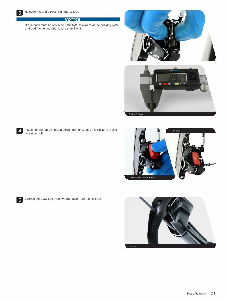
Remove the E-clip from the pad retention bolt, then remove the pad retention bolt from the caliper.
1
2
Needle Nose Pliers 20 mm or 15 mm Thru Axle
2.5 mm QR
26Hose Removal
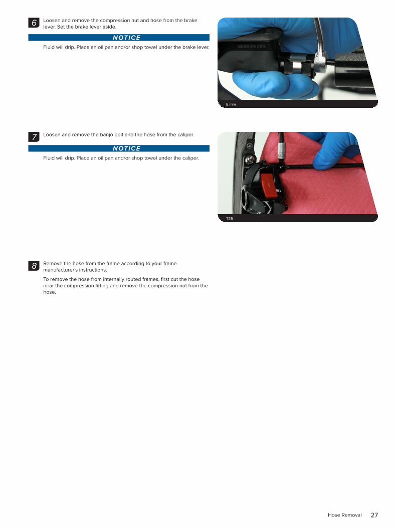
Remove the brake pads from the caliper.
NOTICEBrake pads must be replaced if the total thickness of the backing plate and pad friction material is less than 3 mm.
Install the Monoblock bleed block into the caliper, then install the pad retention bolt.
Loosen the draw bolt. Remove the lever from the aerobar.
Digital Caliper 2.7-3.2 N•m (24-28 in-lb) 22 mm
3
Monoblock Bleed Block 20 mm or 15 mm Thru Axle
2.5 mm QR4
3 mm Rubber-tipped blow gun chuck nozzle 22 mm
5
27Hose Removal
Loosen and remove the compression nut and hose from the brake lever. Set the brake lever aside.
NOTICEFluid will drip. Place an oil pan and/or shop towel under the brake lever.
Loosen and remove the banjo bolt and the hose from the caliper.
NOTICEFluid will drip. Place an oil pan and/or shop towel under the caliper.
Remove the hose from the frame according to your frame manufacturer's instructions.
To remove the hose from internally routed frames, first cut the hose near the compression fitting and remove the compression nut from the hose.
8 mm
6
T25
7
8
28Hose Installation
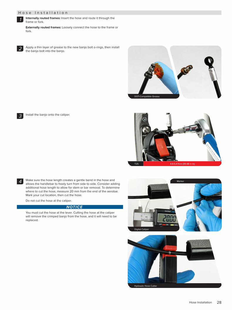
H o s e I n s t a l l a t i o nInternally routed frames: Insert the hose and route it through the frame or fork.
Externally routed frames: Loosely connect the hose to the frame or fork.
Apply a thin layer of grease to the new banjo bolt o-rings, then install the banjo bolt into the banjo.
Install the banjo onto the caliper.
Make sure the hose length creates a gentle bend in the hose and allows the handlebar to freely turn from side to side. Consider adding additional hose length to allow for stem or bar removal. To determine where to cut the hose, measure 20 mm from the end of the aerobar. Mark your cut location, then cut the hose.
Do not cut the hose at the caliper.
NOTICEYou must cut the hose at the lever. Cutting the hose at the caliper will remove the crimped banjo from the hose, and it will need to be replaced.
1
DOT-Compatible Grease 20 mm or 15 mm Thru Axle
2
T25 4.4-5.4 N·m (39-48 in-lb)
3
Digital Caliper 20 mm or 15 mm Thru Axle
Marker QR
Hydraulic Hose Cutter Rubber-tipped blow gun chuck nozzle 22 mm
4
29Hose Installation
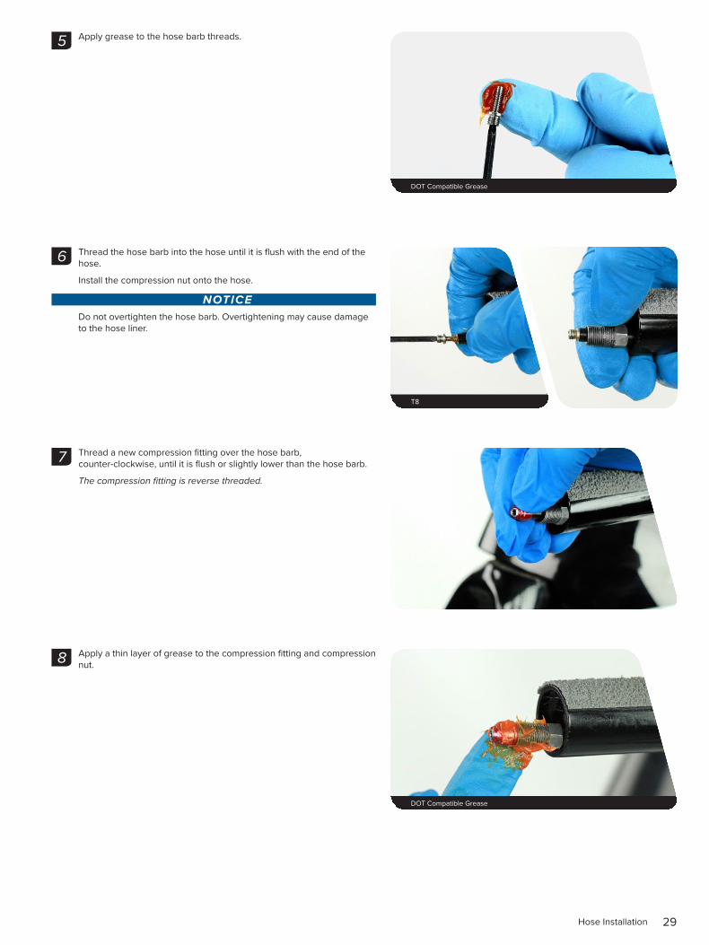
Apply grease to the hose barb threads.
Thread the hose barb into the hose until it is flush with the end of the hose.
Install the compression nut onto the hose.
NOTICE Do not overtighten the hose barb. Overtightening may cause damage to the hose liner.
Thread a new compression fitting over the hose barb, counter-clockwise, until it is flush or slightly lower than the hose barb.
The compression fitting is reverse threaded.
Apply a thin layer of grease to the compression fitting and compression nut.
5
DOT Compatible Grease
6
T8
7
8
DOT Compatible Grease
30Hose Installation
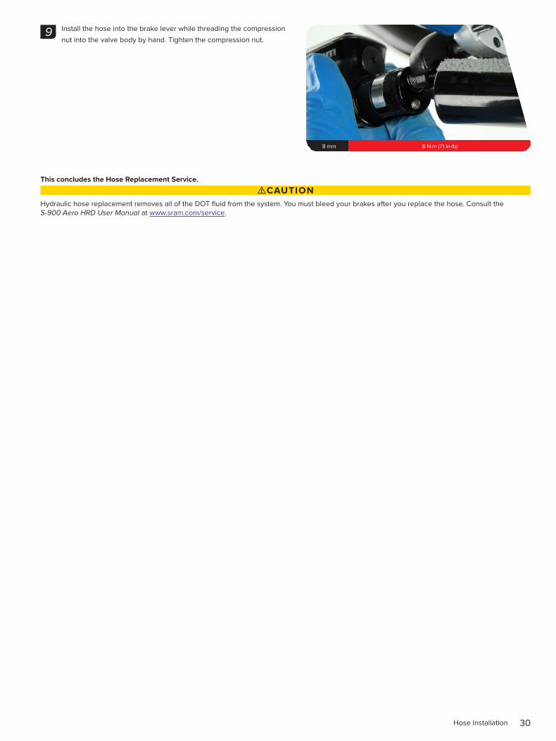
Install the hose into the brake lever while threading the compression nut into the valve body by hand. Tighten the compression nut.
This concludes the Hose Replacement Service. ⚠CAUTION
Hydraulic hose replacement removes all of the DOT fluid from the system. You must bleed your brakes after you replace the hose. Consult the S-900 Aero HRD User Manual at www.sram.com/service.
9
8 mm 8 N·m (71 in-lb)

This publication includes trademarks and registered trademarks of the following companies:
TORX® is a registered trademark of Acument Intellectual Properties, LLC

tmplt 03.30.2017
www.sram.com
ASIAN HEADQUARTERS SRAM Taiwan No. 1598-8 Chung Shan Road Shen Kang Hsiang, Taichung City Taiwan R.O.C.
WORLD HEADQUARTERS SRAM LLC
1000 W. Fulton Market, 4th Floor Chicago, Illinois 60607
USA
EUROPEAN HEADQUARTERS SRAM Europe
Paasbosweg 14-16 3862ZS Nijkerk
The Netherlands


