UNIVERSITY OF PUNE [4362]-113 S. E. (Mech/Mech SW/ Auto) Examination – M a y 2013 Fluid Mechanics ( 2008 Pattern) Total No. of Questions : 12 [Total No. of Printed Pages :3] [Time : 3 Hours] [Max. Marks : 100] (1) Answer any three questions from each section. (2) Answers to the two sections should be written in separate answer-books. (3) Black figures to the right indicate full marks. (4) Your answer will be valued as a whole. (5) Assume suitable data, if necessary. SECTION -1 Q. 1 a) What is the fluid? What are different types of fluid? Explain. (6) b) State and Explain the Newton’s law of viscosity? (4) c) A shaft of 150 mm diameter moves in a sleeve of length 300 mm at a speed of 0.5 m/s under the applications of 200 N force in the directions of its motions. If the clearance between the shaft and sleeves is 0.08 mm, Calculate in viscosity of the lubricating oil in the gap if the applied force is increased to 1000 N, what will be the speed of the sleeve? (8) OR Q. 2. a) What is surface tension? Derive equation of intensity of pressure for . (6) 1)Droplet 2)Bubble 3)Liquid jet b) Differentiate between path line, streakline and streamline. (6) c) If v = ( 10 x 2 y ) i + ( 15xy ) j +( 25t −3xy ) k, find acceleration of a fluid particle at (1,2,-1) and t = 0.5. (6) Q. 3 a) Derive an expression for total pressure and center of pressure for and inclined plane surface, immersed in static mass of a liquid. (6) b) State and explain the Archimedes’s principle. (4) c) Explain with neat sketches, the condition of equilibrium for floating and submerged bodies. (6)
Transcript
UNIVERSITY OF PUNE
[4362]-113S. E. (Mech/Mech SW/ Auto) Examination – M a y 2013
Fluid Mechanics ( 2008 Pattern)
Total No. of Questions : 12 [Total No. of Printed Pages :3][Time : 3 Hours] [Max. Marks : 100]
(1) Answer any three questions from each section.(2) Answers to the two sections should be written in
separate answer-books.(3) Black figures to the right indicate full marks.(4) Your answer will be valued as a whole. (5) Assume suitable data, if necessary.
SECTION -1Q. 1 a) What is the fluid? What are different types of fluid? Explain. (6) b) State and Explain the Newton’s law of viscosity? (4) c) A shaft of 150 mm diameter moves in a sleeve of length 300 mm at a speed of 0.5 m/s under the applications of 200 N force in the directions of its motions. If the clearance between the shaft and sleeves is 0.08 mm, Calculate in viscosity of the lubricating oil in the gap if the applied force is increased to 1000 N, what will be the speed of the sleeve? (8)
OR Q. 2. a) What is surface tension? Derive equation of intensity of pressure for . (6) 1)Droplet 2)Bubble 3)Liquid jet b) Differentiate between path line, streakline and streamline. (6) c) If v= (10 x2 y ) i+ (15xy ) j+( 25t−3xy ) k , find acceleration of a fluid particle at (1,2,-1) and t = 0.5. (6) Q. 3 a) Derive an expression for total pressure and center of pressure for and inclined plane surface, immersed in static mass of a liquid. (6) b) State and explain the Archimedes’s principle. (4) c) Explain with neat sketches, the condition of equilibrium for floating and submerged bodies. (6)
ORQ. 4. a) State and explain Pascal’s law. (2) b) Prove that the center of the pressure of a plane surface is always below the center of gravity when immersed in liquid. (6) c) A wooden block 60cm long, 25cm wide and 20cm deep has its shorter axis vertical with the depth of immersion 10cm. Calculate the position of the metacentre and comment on the stability of the block. (8) Q. 5 a) Derive Euler’s equations of motions along a streamline and further derive Bernoulli’s equation From that. (8) b) Describe a venturimeter and find an expression for measuring discharge of fluid through a pipe with this device. (8)
ORQ. 6. a) What is pitot tube? How is it used? (6) b) What is the notch? Find an expression for measuring the discharge of fluid across a triangular notch. (4) c) With the help of a neat sketch, explain the working of an Orificemeter (6)
SECTION -2Q. 7. a Derive Hagen-Poiseuille equation for steady uniform laminar flow through circular pipe. (8) b Show that Pressure drop Δp of a flowing fluid through a pipe can (8) expressed in the from:
L/ D
Δp=ρ V 2 Ø ¿, μ / ρVD , H / D ¿
ORQ. 8. a) Explain Froude model law and Weber model law. (4) b) A pipe 60 mm diameter and 450 m long slopes upwards at 1 in 50. An oil of viscosity 0.9 Ns /m2 and specific gravity 0.9 is required to be pumped at the rate of 5 lps. (12) 1) Is the flow laminar? 2) What is the power of the pump required assuming an overall efficiency Of 65% 3) What is the center line velocity and velocity gradient at pipe wall? Q. 9. a) Derive the expression for loss of head due to sudden contraction. (8)
b) When a sudden contraction in introduced in a horizontal pipeline from 500mm diameter to 250mm diameter, the pressure changes from 105 kN/ m2 to 69 kN/ m2 . If the co-efficient of contraction is assumed to be 0.65, Calculate the water flow rate. Instead of this if sudden expansion is introduce of same size and if the pressure at the 250 mm section is 69 kN/ m2 , What is the pressure at the 500 mm enlarge portion? (10)
ORQ. 10. a) Sketch Moody chart and explain how it is to be used? (6) b) Two sharp ended pipes of diameters of 50 mm and 100 mm respectively, each of length 100m are connected in parallel between two reservoirs which have a difference of laver of 10m. If the friction factor for each pipe is 0.32, calculate:
1) Rate of flow for each pipe and 2) The diameter of a single pipe 100m long which would give the same discharge, if it were substituted for the original two pipes. (12)
Q.11. a) Explain briefly Boundary layer thickness with different types? (8) b) Find power required to overcome boundary friction to cruise a passenger ship of 300m length and 12 m draft at 40 km/h. If ρ=1030kg /m3 and
y=1×10⁻⁶ m2/ s.
(8)
ORQ. 12. a) Prove the coefficient of lift of an aerofoil body depend on angle of attack (6) b) A sphere of 4 cm diameter made of Aluminum (sp.gr. = 2.8) is attached to a string and suspended from the roof of a wind tunnel. If an air stream of 30m/s flows past the sphere, Find the inclination of the string and tension in the string.
5If ℜ>3× 10¿
ρ=1.2kg /m3 , y=1.5× 12−5 m2/s ,CD=0.5( if 104
<ℜ<3×10⁵) ,CD=0.2¿
(10)
1
UNIVERSITY OF PUNE [4362]-117
S. E. (Mech.) Examination-2013 I.C. Engine
(2008 Course) Total No. Of Questions: 12 [Total No. Of Printed Pages: 5]
[Time: 3 Hours] [Max. Marks: 100]
Instructions: (1) Answer any three questions from each section. (2) Answers to the two sections should be written in separate
answer-books. (3) Black figures to the right indicate full marks. (4) Neat diagrams must be drawn wherever necessary. (5) Use of logarithmic tables, slide rule, Molliercharts,
electronic pocket calculator and steam tables is allowed. (6) Assume suitable data, if necessary.
SECTION-I
Q. 1. A) Compare Otto, and Dual cycle for: (8)
i. Constant maximum pressure and same heat input
ii. Same compression ratio and same heat input
iii. Same max pressure and same output
B) A S.I. engine working on Otto cycle takes the air in at 0.97 bar (10)
and 40˚C. The compression ratio of the cycle is 7. The heat supplied
during the cycle is 1.2 MJ/kg of working fluid. Find:
i. Air standard efficiency of the cycle
ii. Maximum temperature attained in the cycle
iii. Maximum pressure attained in the cycle
iv. Work done per kg of working fluid
2
v. Mean effective pressure
Take ϒ=1.4, Cv=720J/kg-k
OR
Q. 2. A) Derive an expression for thermal efficiency of a diesel cycle with (8)
usual notation.
B) Explain pumping and friction losses and their effects on the power (5)
Output of the engine.
C) State the assumption made for air standard cycle. (5)
Q. 3. A) Explain with neat sketch the following systems of a carburetor (7)
i. Idling system
ii. Chock
B) The diameter for a venture of a simple carburetor is 2cm and its (9)
Cda=0.85. The fuel nozzle diameter is 1.25 mm and Cdf=0.66.
The lip of the fuel nozzle is 5 mm. Find:
i. A:F ratio for pressure drop of 0.07 bar when nozzle lip is neglected.
ii. A:F ratio when the nozzle lip is considered.
iii. The minimum velocity of air required to start the fuel flow when lip
Provided.
Take density of air = 1.2 kg/m3 and density of fluid=750 kg/m3.
OR
Q. 4. A) Explain the basic requirements of a good combustion chamber of (8)
S.I. engine and draw a neat sketch of T-head combustion chamber.
B) Explain the phenomenon of pre-ignition. How pre-ignition leads to (8)
detonation and vice-versa? Explain how pre-ignition can be detected?
3
Q. 5.A) How air-less injection systems are classified? Explain the working (8)
of distributer system with the help of neat sketch. Discuss their relative
merits and demerits.
B) What are the functions of a nozzle? Explain various types of nozzles (8)
With neat sketches.
OR
Q. 6.A) Explain the stage of combustion in CI engine. (8)
B) What is meant by ignition delay? Explain the effect of following (8)
factors on the ignition delay with suitable reason.
i. Compression Ratio
ii. Engine size
iii. Engine speed
SECTION-II
Q. 7. A) What are the basic requirements of an ideal ignition system? (4)
B) What are the desirable properties of good lubricating oil? (4)
C) What are the main functions of lubricating system? Explain dry (8)
Sump lubricating system.
OR
Q. 8.A) Define the functions of radiators. Discuss different type of matrices (8)
used with these radiators with neat sketch.
B) Explain the working of spring loaded mechanical governor with the (8)
help of neat sketch used for Diesel engine.
Q. 9. A) The following observations are made during a trial on an oil engine (12)
4
-Motor power to start the engine =10kW
-R.P.M.=1750
-Brake Torque = 327.5Nm
-Fuel used = 15 kg/hr
-C.V. of fuel used = 42MJ/kg
-Air supplied = 4.75 kg/min
-Quantity of cooling water = 16 kg/min
-Outlet temperature of cooling water = 65.8˚C
-Room temperature = 20.8˚C
-Exhaust gas temperature = 400˚C
-Take Cpw = 4.2kj/kg. K and Cpg = 1.25kj/kg.K
Determine :
i. B.P.
ii. Mechanical efficiency
iii. BSFC
iv. Draw a neat balance sheet on k W basis and percentage basis.
B) Write a short note on: (6)
i. Heat balance sheet.
ii. Various factors affecting volumetric efficiency.
OR
Q. 10. A) A six cylinder gasoline engine operators on the four stroke cycle. (10)
The bore of each cylinder is 80 mm and stroke 100 mm. the clearance
Volume per cylinder is 70CC. At a speed of 4000 r.p.m., the fuel
Consumption is 30 kg/hr. and the torque developed is 150 N.m
5
Calculate:
i. The brake power
ii. The brake mean effective pressure
iii. The brake mean thermal efficiency
Assume the C.V. of fuel as 43,000 kJ/kg. Also estimate relative efficiency
When engine works on constant volume cycle with = 1.4 for air.
B) What is the dynamometer? Name the various types of dynamometer. (8)
Explain the Eddy current dynamometer with the help of a neat sketch.
Q. 11. A) Enlist the specification of an automobile engine. (6)
B) What is air pollution? Explain the contributors to air pollution and (6)
their harmful effects on humans beings.
C) Mention the modifications required if hydrogen is used in SI engine (4)
(2008 COURSE)[Total No. of Questions :12] [Total No. of Printed Pages :6][Time : 3 Hours] [Max. Marks : 100]
Instructions :
1) Answers 3 questions from Section I and 3 questions from Section II 2) Answers to two section should be written in separate answer-book.3) Neat diagrams must be must be drawn wherever necessary.4) Figures to the right indicate full marks.5) Your answers will be valued as whole.6)Use of logarithmic tables slide rule, Mollier charts, electronic pocket calculator and steam tables is allowed.7) Assume suitable data, if necessary.
SECTION ІUNIT NO : 1
Q1) a)State clausius and kelvin planck statements of second law of Thermo-dynamics and prove their equivalence [08]
b) Explain the principal of increase of entropy [08]
(OR)
Q2) (a) Write a short note on: PMM-І and PMM- ІІ [04]
(b) What are the limitations of first law of Thermodynamics [04]
(c) Explain clausius inequality? [04]
(d) What is COP? How will you calculate COP for a refrigerator and
heat pump? [04]
1
UNIT NO : 2
Q3)(a) Explain Helmholtz and Gibbs function [04]
(b) Explain second law of efficiency [04]
(c) Explain : [08]
1) Available energy
2) Unavailable energy
3) Dead state
4) Equation of state
OR
Q4) a) 60 liters of hydrogen at 20°c and 1 bar is compressed adiabatically to 9.8 bar. It is then cooled at constant volume to a pressure P3 such as to have temp of 20°c and further expanded isothermally so as to reach initial state find:
1) Work done during each process
2) Change in internal energy during each process
Take cp = 14.4 kj/kg k
Take cv = 10.28 kj/kg k
Show the process on P-V and T-S plane [10]
(b) Derive an expression for work done if process is polytropic. [10]
UNIT : 3
Q5)(a) Compare carnot and Rankine cycle [4]
(b) Explain the following terms: [08]
2
1) Wet steam
2) Dry steam
3) Superheated steam
4) Critical point
(c) With a neat Sketch, explain working of separting and throttling Calorimeter [06]
(OR)
Q6) a) A steam power plant operating on rankine cycle, receives steam at 3.5 MPa and 350°c. it is exhausted to condenser at 0.1 bar calculate :
1) Energy supplied per kg of steam generated in boiler
2) Quality of steam entering the condenser
3) Rankine cycle efficiency considering feed pump work
4) Specific steam consumption [12]
c)Explain the effects various parameters on the performance of the Rankine cycle [06]
SECTION ІІ
UNIT NO : 4
Q7) a) Explain bomb calorimeter with a neat sketch [06]
b) A fuel having chemical formula C7 H 16 is burnt with 10% excess air. Assume 90% carbon burnt to CO2 and remaining to CO. Determine volumetric analysis of dry flue gases. [10]
OR
Q8) a)Explain Orsat apparatus with a neat sketch [06]
3
b) A hydrocarbon fuel has the following orsat analysis:
CO2 = 12.5%
CO = 0.3%
O2 = 3.1%
N2 = 84.1%
Determine
1) Air-fuel ratio
2) Fuel composition on mass basis
3) Percentage of excess air supplied [10]
UNIT NO : 5
Q9)
(a) Define:
1) Isothermal efficiency
2) Volumetric efficiency
3) F.A.D [06]
(b)Explain Vane compressor with a neat sketch [04]
(c) For a single stage single acting reciprocating air compressor, actual volume of air taken in is 10m3/min. Initial intake pressure is 1.013 bar and initial temp is 27°C. Final pressure is 900Kpa, clearance is 6% of stroke. Compressor runs at 400 rpm.
Assume: L/D = 1.25 and index of compression = 1.3
4
Determine : 1) volumetric efficiency
2) Cylinder dimensions
3) Indicated power [06]
OR
Q10)
(a) Explain the methods of improving isothermal efficiency of air compressor [06]
(b)A 2 stage single acting ir compressor takes in air at 1 bar and 300k. Air is discharged at 10bar. The intermediate pressure is ideal and intercooling is perfect. The law of compression is PV1.3=C
The rate of discharge is 0.1 kg/sec. Find
1) Power required to drive the compressor
2) Saving in work compared to single stage
3) Isothermal efficiency for single and multistage
4) Heat rejected in intercooler
Take Cp= 1kj/kg k and R= 0.287 kj/kg k [10]
UNIT NO : 6
Q11)
(a) Write a short note on : boiler draught [04]
(b)Explain : 1) Boiler efficiency
2) Equivalent of evaporation [04]
(c) Write a short note on IBR [04]
5
(d) Explain : superheater with a neat sketch [06]
OR
Q12)
a) During a boiler trail, the following readings were recorded :
Duration of trail : 8 hours
Steam pressure : 14bar
Dryness fraction : 0.973
Feed water evaporated : 26,700
Feed water temp : 50°C
Coal used : 4260 kg
Calorific value of coal : 28,900 kj/kg
Air used : 17 kg/kg of coal
Temp of flue gases : 344°C
Boiler room temp : 21°C
Cp of flue gases : 1.1 kj/kg k
Determine
1) Boiler efficiency
2) equivalent of evaporation
3) heat lost to the flue gases / kg of coal and in percentage [10]
(b) State the salient features of high pressure boilers [05]
(c) Compare boiler mountings and accessories [03]
6
Total No. of Questions : 12 [Total No. of Printed Pages :7]
[3661]-119S. E.(Mechanical) (Mechanical
S/W) (Semester - I I) Examination -2012
STRENGTH OF MACHINE ELEMENT(202051) (2008 Pattern)
[Time : 3 Hours] [Max. Marks : 100]
(1)Answers to the two sections should be
written in separate answer-books.(2) Black figures to the right indicate full marks.(3) Neat diagrams must be drawn wherever necessary.(4) Use of logarithmic tables, slide rule,Mollier
charts, electronic pocket calculator and steam tables is allowed.
(5) Assume suitable data, if necessary.
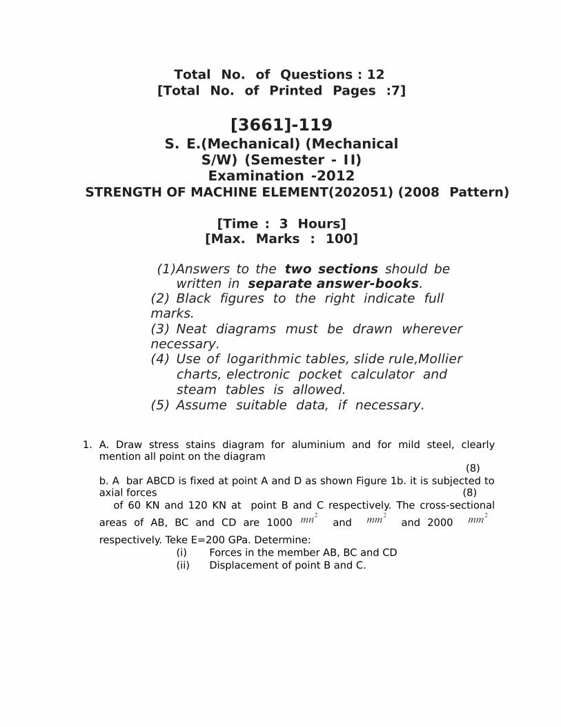
1. A. Draw stress stains diagram for aluminium and for mild steel, clearly mention all point on the diagram
(8) b. A bar ABCD is fixed at point A and D as shown Figure 1b. it is subjected to axial forces (8) of 60 KN and 120 KN at point B and C respectively. The cross-sectional
areas of AB, BC and CD are 1000 mn2 and mm2
and 2000 mm2
respectively. Teke E=200 GPa. Determine:(i) Forces in the member AB, BC and CD(ii) Displacement of point B and C.
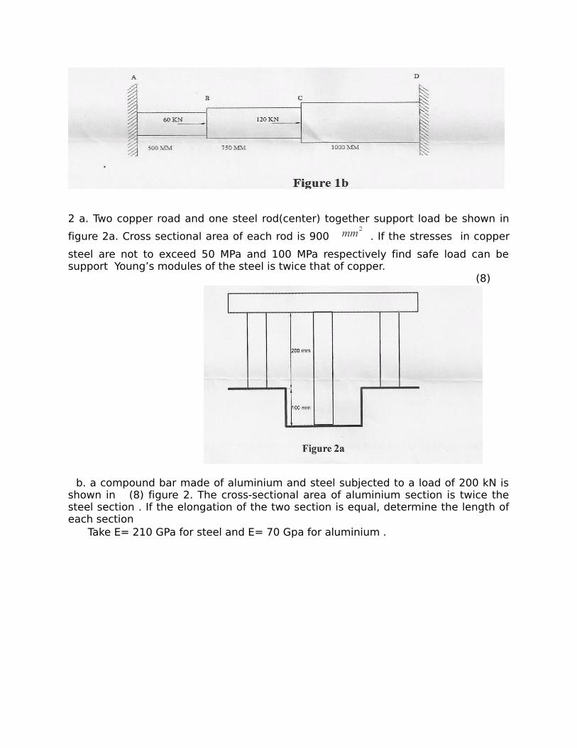
2 a. Two copper road and one steel rod(center) together support load be shown in
figure 2a. Cross sectional area of each rod is 900 mm2. If the stresses in copper
steel are not to exceed 50 MPa and 100 MPa respectively find safe load can be support Young’s modules of the steel is twice that of copper.
(8)
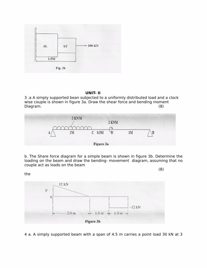
b. a compound bar made of aluminium and steel subjected to a load of 200 kN is shown in (8) figure 2. The cross-sectional area of aluminium section is twice the steel section . If the elongation of the two section is equal, determine the length of each section Take E= 210 GPa for steel and E= 70 Gpa for aluminium .
UNIT- II3 .a A simply supported bean subjected to a uniformly distributed load and a clock wise couple is shown in figure 3a. Draw the shear force and bending moment Diagram. (8)
b. The Share force diagram for a simple beam is shown in figure 3b. Determine the loading on the beam and draw the bending- movement diagram, assuming that no couple act as loads on the beam
(8)the
4 a. A simply supported beam with a span of 4.5 m carries a point load 30 kN at 3
meters from the left support. If for the section, Ixx = 5 x 10⁻⁶ m4
and E =200
GPa , find (8)(i) The defection under the load (ii) The position and amount of maximum deflection
b. A beam of length 6 m is simply supported at it’s ends and carries two point laods of 48 kN and 40 kN at a distance of 1 m and 3 m respectively from the left support find: 1. Deflection under each load 2. Maximum deflection 3. The point at which maximum deflection occurs.
(E= 2 x 10⁵
N/ mm2
and I = 85 x 106mm4
)
(8)
UNIT- III
5. a Derive the formulate fro normal street and strees on an oblique plane in which at an angle with the axis of minor stress.
(8)
b. an element in a stresses material has tendile stress of 500 MPa and compressive stress of 304 MPa acting on two mutually perpendicular planes and equal shear stresses of 100 MPa in these maximum shearing stress.
(10)
OR6. a. List theories of failure and explain their significance also explain the application of each theory of failure
(8)
b. A blot is under an axial pull of 24 kN together with a transverse shear force of 5 kN. Calculate the diameter if bolt using
(10)
(i) Maximum principle stress theory (ii) Maximum shear stress theory(iii) Strain energy theory
SECTION – II UNIT - IV
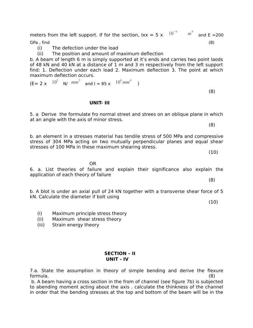
7.a. State the assumption in theory of simple bending and derive the flexure formula. (8) b. A beam having a cross section in the from of channel (see figure 7b) is subjected to abending moment acting about the axis . calculate the thinkness of the channel in order that the bending stresses at the top and bottom of the beam will be in the
ratio 7:3, respectively. (8)
OR8. a. A Rectangular beam is simply supported at the end and carries a point load at the center . Establish the relation between maximum bending stress and maximum shear stress (8)
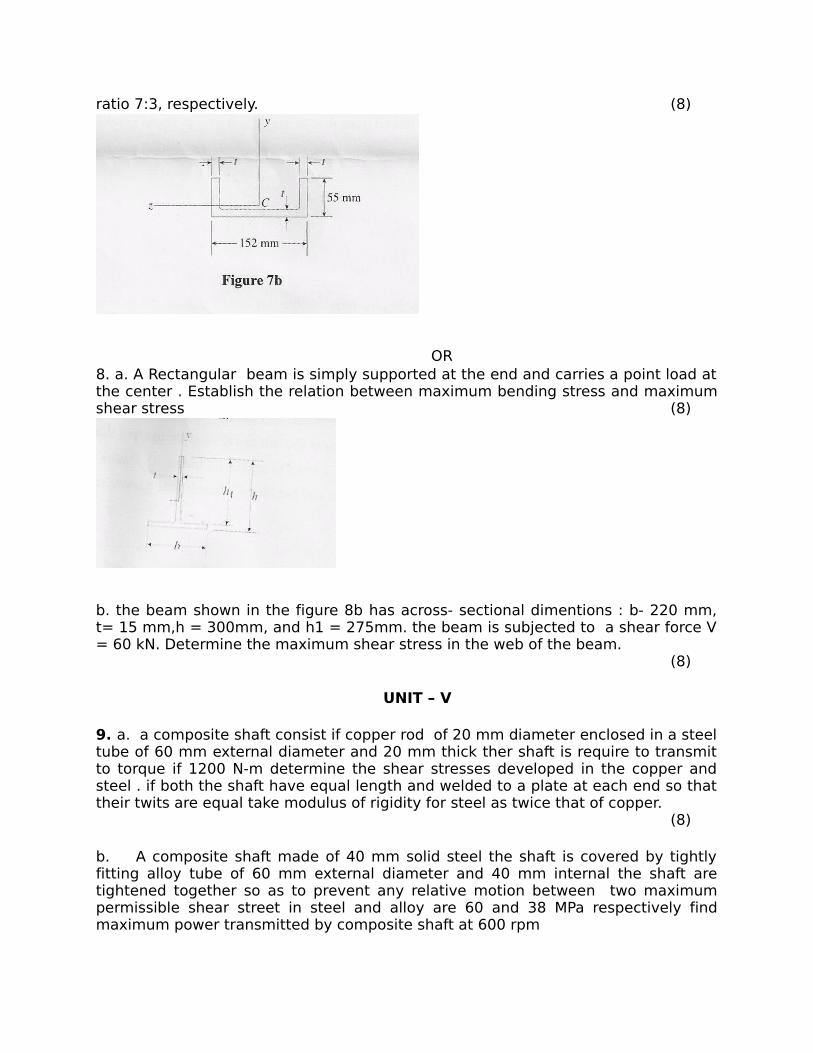
b. the beam shown in the figure 8b has across- sectional dimentions : b- 220 mm, t= 15 mm,h = 300mm, and h1 = 275mm. the beam is subjected to a shear force V = 60 kN. Determine the maximum shear stress in the web of the beam.
(8)
UNIT – V 9. a. a composite shaft consist if copper rod of 20 mm diameter enclosed in a steel tube of 60 mm external diameter and 20 mm thick ther shaft is require to transmit to torque if 1200 N-m determine the shear stresses developed in the copper and steel . if both the shaft have equal length and welded to a plate at each end so that their twits are equal take modulus of rigidity for steel as twice that of copper.
(8)
b. A composite shaft made of 40 mm solid steel the shaft is covered by tightly fitting alloy tube of 60 mm external diameter and 40 mm internal the shaft are tightened together so as to prevent any relative motion between two maximum permissible shear street in steel and alloy are 60 and 38 MPa respectively find maximum power transmitted by composite shaft at 600 rpm
Take G steel = 80 GPa and Galloy = 44 GPa (8)
OR
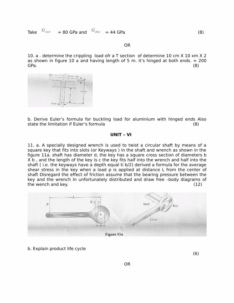
10. a . determine the crippling load ofr a T section of determine 10 cm X 10 xm X 2 as shown in figure 10 a and having length of 5 m. it’s hinged at both ends. = 200 GPa. (8)
b. Derive Euler’s formula for buckling load for aluminium with hinged ends Also state the limitation if Euler’s formula (8)
UNIT – VI
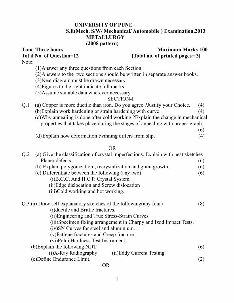
11. a. A specially designed wrench is used to twist a circular shaft by means of a square key that fits into slots (or Keyways ) in the shaft and wrench as shown in the figure 11a. shaft has diameter d, the key has a square cross section of diameters b X b , and the length of the key is c the key fits half into the wrench and half into the shaft ( i.e. the keyways have a depth equal ti b/2) derived a formula for the average shear stress in the key when a load p is applied at distance L from the center of shaft Disregard the effect of friction assume that the bearing pressure between the key and the wrench In unfortunately distributed and draw free –body diagrams of the wench and key. (12)
b. Explain product life cycle (6)
OR
12. a Design a knuckle joint for a tie rod of circular section for a maximum pull of 15
kN . The yield strength of material is 315 N/ mm2 .Permissible stresses are same in
tension and compression . take factor of safety as 2.(12)
b. Write a short note on design synthesis (6)
UNIVERSITY OF PUNE S.E(Mech. S/W/ Mechanical/ Automobile ) Examination,2013 METALLURGY (2008 pattern)Time-Three hours Maximum Marks-100Total No. of Question=12 [Total no. of printed pages= 3]Note: (1)Answer any three questions from each Section.
(2)Answers to the two sections should be written in separate answer books.(3)Neat diagram must be drawn necessary.(4)Figures to the right indicate full marks.(5)Assume suitable data wherever necessary.
SECTION-IQ.1 (a) Copper is more ductile than iron. Do you agree ?Justify your Choice. (4) (b)Explain work hardening or strain hardening with curve (4) (c)Why annealing is done after cold working ?Explain the change in mechanical
properties that takes place during the stages of annealing with proper graph.(6)
(d)Explain how deformation twinning differs from slip. (4)
ORQ.2 (a) Give the classification of crystal imperfections. Explain with neat sketches
Planer defects. (6)(b) Explain polygonization , recrystalization and grain growth. (6)(c) Differentiate between the following (any two) (6)
(i)B.C.C. And H.C.P. Crystal System (ii)Edge dislocation and Screw dislocation (iii)Cold working and hot working.
Q.3 (a) Draw self explanatory sketches of the following(any four) (8) (i)ductile and Brittle fractures. (ii)Engineering and True Stress-Strain Curves (iii)Specimen fixing arrangement in Charpy and Izod Impact Tests. (iv)SN Curves for steel and aluminium. (v)Fatigue fractures and Creep fracture. (vi)Poldi Hardness Test Instrument. (b)Explain the following NDT: (6) (i)X-Ray Radiography (ii)Eddy Current Testing (c)Define Endurance Limit. (2) OR
1
Q.4 (a)Explain why breaking strength is lower than ultimate tensile strength in ductile materials.Derive the relation between engineering and true stress-strain values.
(4) (b)Suggest suitable hardness testing method for (4) (i)Gray Cast Iron (ii)Gold Plated Surface (iii)Synthetic Rubber (iv)Crank Shaft (c)Why magna flux method is used in both the longitudinal and transverse
directions for testing components? (4) (d)What is creep?In which application should it be considered ?How the creep
resistance is improved? (4)
Q.5 (a)What is critical temperature?What do you understand by A0 A1 A2 A3
and Acm? (4) (b)Explain the classification of Steel: (4) (i)On the basis of carbon content. (ii)On the basis of de-oxidation. (c)What is the alloy steel?What are the effects of alloying elements?(any two
elements) (4) (d)Draw Iron Carbon Equilibrium diagram ,and show critical temperatures and
various phases on it. (4) ORQ.6 (a)Write short note on:(ant two) (8) (i)HSLA (ii)Dual Phase Steels (iii)Tool Steels (b)Why are the cast irons preferred to steels for certain applications?/Explain with
specific examples. (4) (c)Compare and contrast between austenitic and martensitic stainless steels. (4) SECTION-IIQ.7(a)Draw TTT diagram for 0.8% C.What information is obtained from this diagram
with respect to annealing,normalizing and hardening treatments? (8) (b)Explain the following;(any Three) (6) (i)Critical Cooling Rate. (ii)Retained Austenite (iii)Windmanstatten Structures (iv)Cryogenic treatment (c)Differentiate between Carburizing and Nitriding. (4)
2
ORQ.8(a)Represent martempering ,austempering,patenting and ausforming on TTT
diagram.State clearly what is the transformation product separately after each treatment. (6)
(b)What is the hardenability?How it is measured?Explain in detail. (6) (c)What is the tempering of steels?Why are hardened steels tempered?Explain the
changes in properties that occur during tempering? (4) (d)Explain the principle of Induction Hardening. (2)
Q.9(a)Draw microstructures and give one application of: (6) (i)White cast iron (ii)Gray cast iron (iii)S.G.Iron (b)What are the advantages and limitations of Powder Metallurgy Process. (4) (c)Explain the following characteristics of metal powder:(any three) (6) (i)Apparent Density (ii)Green Density (iii)Green Strength (iv)Green Spring ORQ.10(a)Enlist the types of brasses.Explain any one. (4) (b)Describe the factors which control graphitization in cast iron. (4) (c)What is the self lubricated bearing?What is their unique advantage over other
bearing?Give their applications? (4) (d)What is the importance of sintering. Can this step be omitted in powder
Metallurgy. (4)
Q.11 (a)What is cemented carbide composite?How is it manufactured? (4)(b)What do you understand from the following terms related to materials? (8)
(c)What do you understand by the term glass?How does it differ from metals?(4)OR
Q.12 (a) What are refractory materials?Give few examples of refractory materials. (4)(b)Write short note:(any three) (12)
(i)Electrical contact materials (ii)Ceramic materials (iii)Role of design engineer and selection of advance materials (iv)Special Cutting materials (v)Super Alloys
3
UNIVERSITY OF PUNE [4362-114]
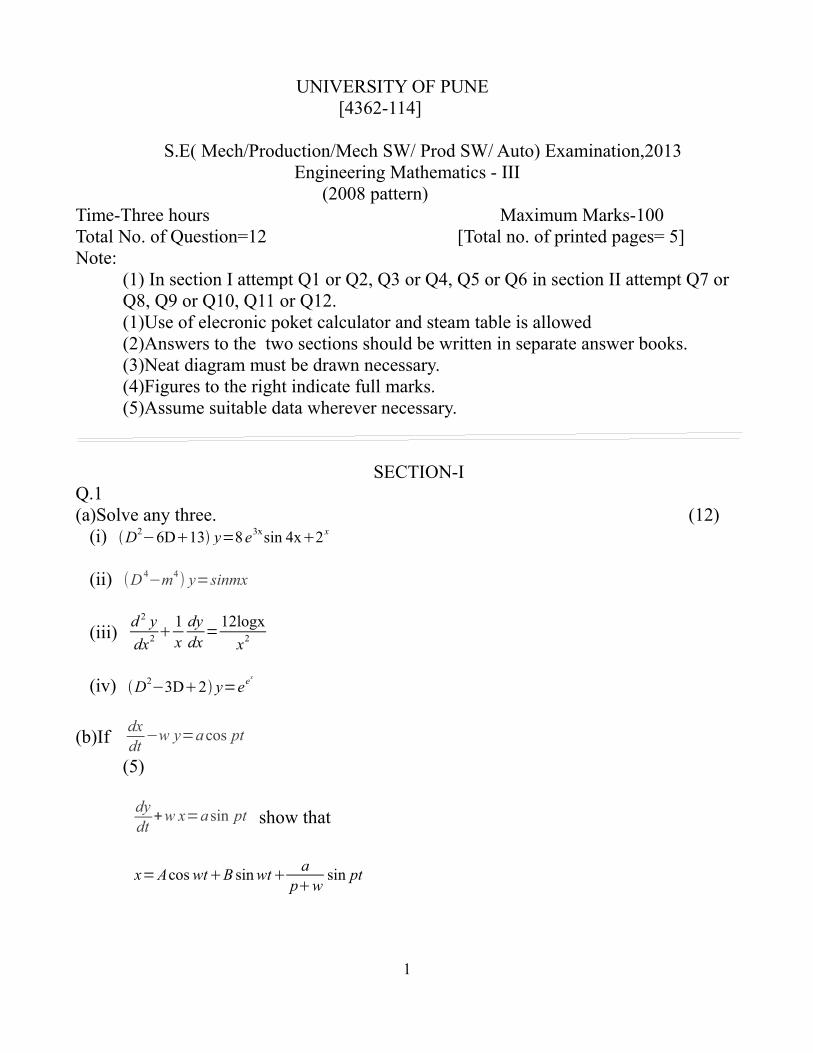
S.E( Mech/Production/Mech SW/ Prod SW/ Auto) Examination,2013 Engineering Mathematics - III (2008 pattern)Time-Three hours Maximum Marks-100Total No. of Question=12 [Total no. of printed pages= 5]Note:
(1) In section I attempt Q1 or Q2, Q3 or Q4, Q5 or Q6 in section II attempt Q7 or Q8, Q9 or Q10, Q11 or Q12.(1)Use of elecronic poket calculator and steam table is allowed(2)Answers to the two sections should be written in separate answer books.(3)Neat diagram must be drawn necessary.(4)Figures to the right indicate full marks.(5)Assume suitable data wherever necessary.
SECTION-IQ.1 (a)Solve any three. (12) (i) D2
−6D13 y=8 e3xsin 4x2x
(ii) (D 4−m4
) y=sinmx
(iii)d 2 y
dx2 1x
dydx
=12logx
x2
(iv) D2−3D2 y=eex
(b)If dxdt
−w y=acos pt
(5)
dydt
+w x=a sin pt show that
x=Acos wtB sin wta
pwsin pt
1
y=B cos wt−A sin wt−a
pwcos pt
OR
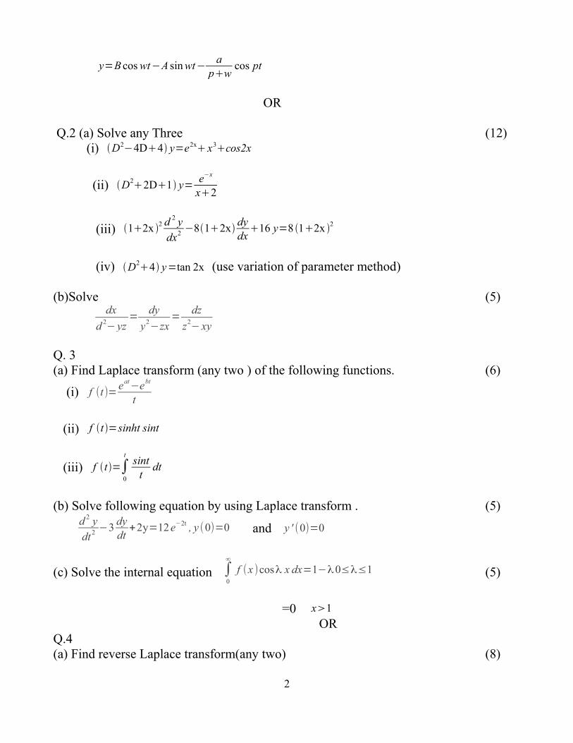
Q.2 (a) Solve any Three (12) (i) D2−4D4 y=e2x x3cos2x
(ii) D22D1 y=
e−x
x2
(iii) 12x 2 d 2 y
dx2 −812xdydx
16 y=8 12x 2
(iv) D24 y=tan 2x (use variation of parameter method)
(b)Solve (5)dx
d 2− yz
=dy
y2−zx
=dz
z2− xy
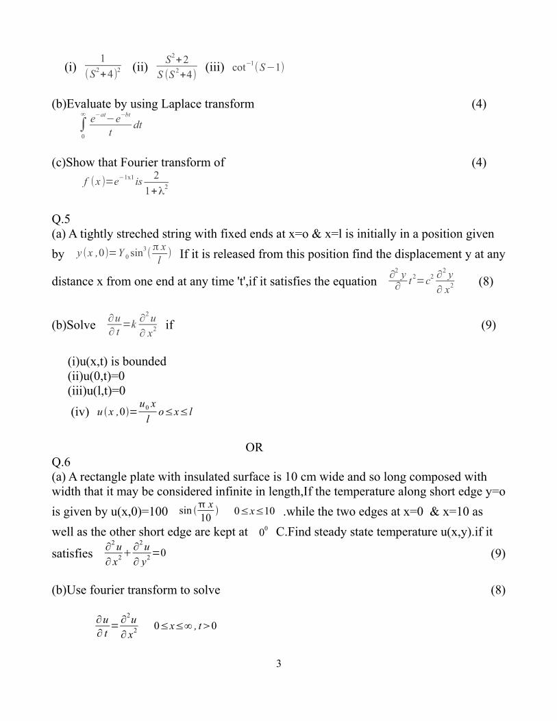
Q. 3(a) Find Laplace transform (any two ) of the following functions. (6)
(i) f (t)=eat
−ebt
t
(ii) f t =sinht sint
(iii) f t=∫0
tsint
tdt
(b) Solve following equation by using Laplace transform . (5)
Q.5 (a) A tightly streched string with fixed ends at x=o & x=l is initially in a position given
by y (x ,0)=Y 0 sin3(π xl
) If it is released from this position find the displacement y at any
distance x from one end at any time 't',if it satisfies the equation ∂
2 y∂
t 2=c2 ∂
2 y∂ x2 (8)
(b)Solve ∂u∂ t
=k∂
2 u∂ x2 if (9)
(i)u(x,t) is bounded (ii)u(0,t)=0 (iii)u(l,t)=0
(iv) u x ,0=u0 x
lo≤x≤ l
ORQ.6(a) A rectangle plate with insulated surface is 10 cm wide and so long composed with width that it may be considered infinite in length,If the temperature along short edge y=o
is given by u(x,0)=100 sin x10
0≤x≤10 .while the two edges at x=0 & x=10 as
well as the other short edge are kept at 00 C.Find steady state temperature u(x,y).if it
satisfies ∂
2 u∂ x2
∂2 u
∂ y2 =0 (9)
(b)Use fourier transform to solve (8)
∂u∂ t
=∂
2u∂ x2 0≤x≤∞ , t0
3
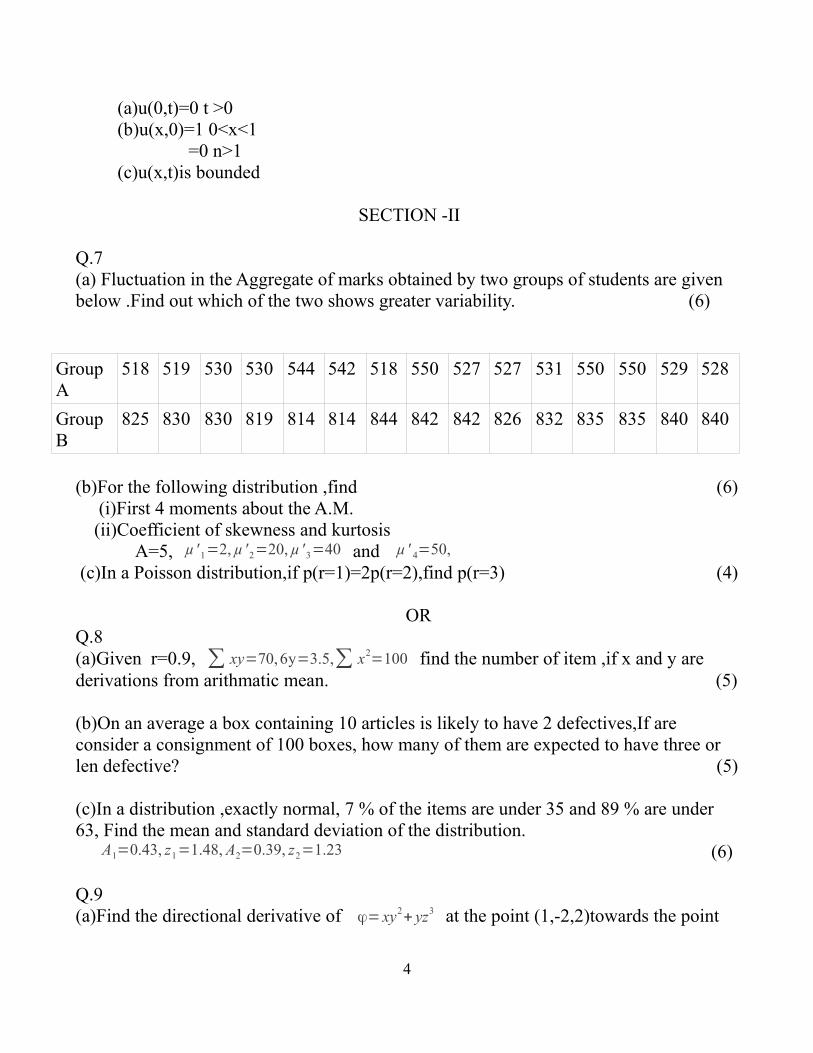
(a)u(0,t)=0 t >0 (b)u(x,0)=1 0<x<1
=0 n>1 (c)u(x,t)is bounded
SECTION -II
Q.7(a) Fluctuation in the Aggregate of marks obtained by two groups of students are given below .Find out which of the two shows greater variability. (6)
(b)For the following distribution ,find (6) (i)First 4 moments about the A.M. (ii)Coefficient of skewness and kurtosis A=5, µ' 1=2, µ' 2=20, µ' 3=40 and µ' 4=50,
(c)In a Poisson distribution,if p(r=1)=2p(r=2),find p(r=3) (4)
ORQ.8 (a)Given r=0.9, ∑ xy=70,6y=3.5,∑ x2
=100 find the number of item ,if x and y are derivations from arithmatic mean. (5)
(b)On an average a box containing 10 articles is likely to have 2 defectives,If are consider a consignment of 100 boxes, how many of them are expected to have three or len defective? (5)
(c)In a distribution ,exactly normal, 7 % of the items are under 35 and 89 % are under 63, Find the mean and standard deviation of the distribution. A1=0.43, z1=1.48, A2=0.39, z2=1.23 (6)
Q.9(a)Find the directional derivative of ϕ= xy2+ yz3 at the point (1,-2,2)towards the point
4
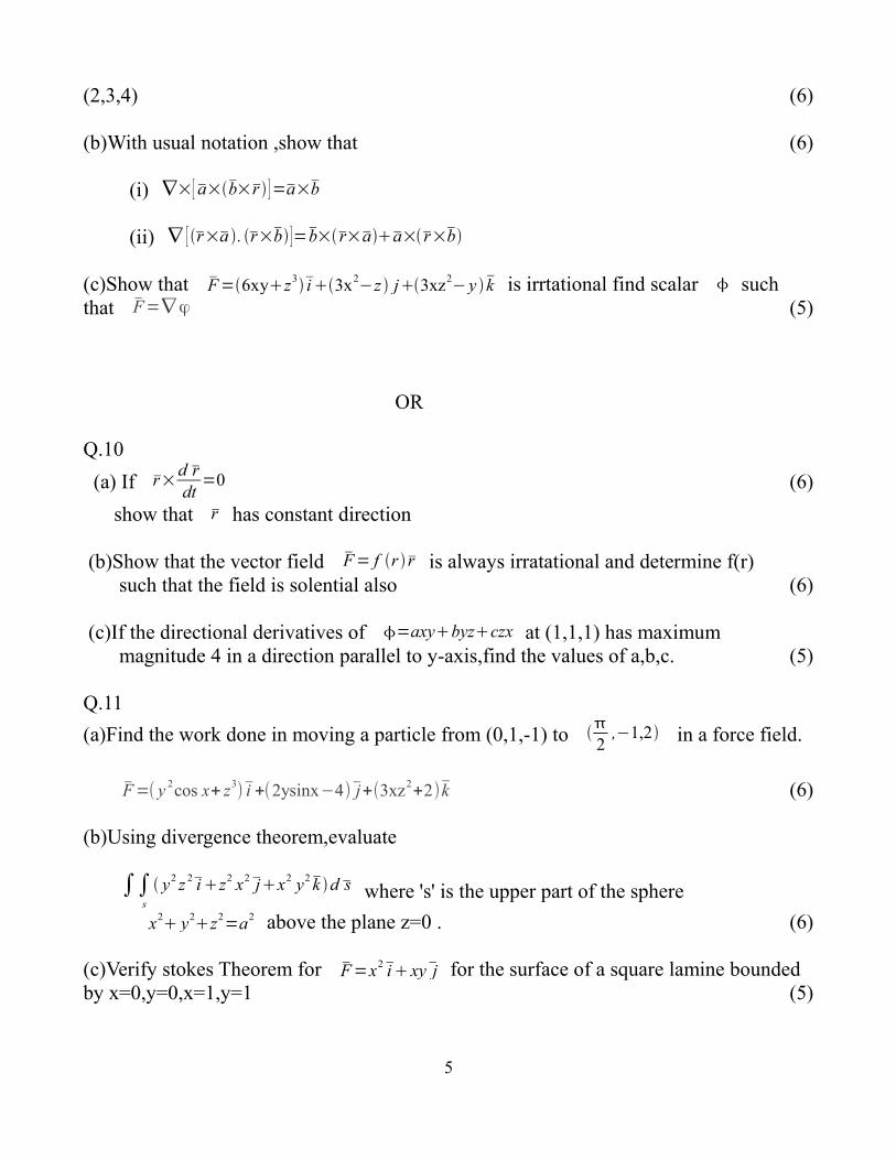
(2,3,4) (6)
(b)With usual notation ,show that (6)
(i) ∇×[ a×b×r ]=a×b
(ii) ∇ [ r×a . r×b ]=b×r×aa×r×b
(c)Show that F=6xyz3i 3x2
−z j3xz2− y k is irrtational find scalar such
that F=∇ϕ (5)
OR
Q.10
(a) If r×d rdt
=0 (6)
show that r has constant direction
(b)Show that the vector field F= f r r is always irratational and determine f(r) such that the field is solential also (6)
(c)If the directional derivatives of =axybyzczx at (1,1,1) has maximum magnitude 4 in a direction parallel to y-axis,find the values of a,b,c. (5)
Q.11
(a)Find the work done in moving a particle from (0,1,-1) to 2
,−1,2 in a force field.
F=( y 2cos x+ z3
) i +(2ysinx−4) j+(3xz2+2) k (6)
(b)Using divergence theorem,evaluate
∫∫s
y2 z 2i z2 x2 jx2 y2 k d s where 's' is the upper part of the sphere
x2 y2
z2=a2 above the plane z=0 . (6)
(c)Verify stokes Theorem for F=x2 i xyj for the surface of a square lamine bounded by x=0,y=0,x=1,y=1 (5)
5
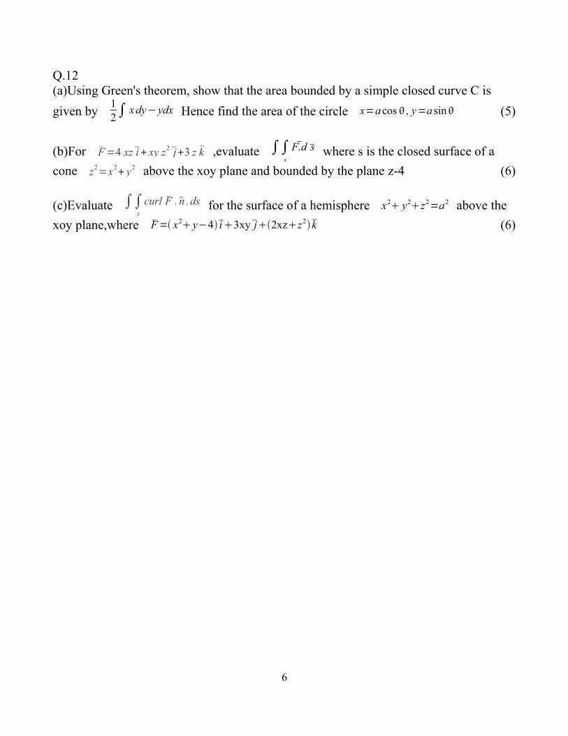
Q.12 (a)Using Green's theorem, show that the area bounded by a simple closed curve C is
given by 12∫ xdy− ydx Hence find the area of the circle x=a cos , y=a sin (5)
(b)For F=4 xz i + xy z2 j+3 z k ,evaluate ∫∫s
F.d s where s is the closed surface of a
cone z2=x2
+ y2 above the xoy plane and bounded by the plane z-4 (6)
(c)Evaluate ∫∫s
curl F . n . ds for the surface of a hemisphere x2 y2z2=a2 above the
xoy plane,where F= x2 y−4i 3xyj2xzz2 k (6)
6
[Total No. of Questions : 12] [Total No. Of Printed Pages: 3]
UNIVERSITY OF PUNE[4362]-115
S. E.(Mechanical/ Automobile)Examination –2013
MANUFACTURING PROCESSES [2008 COURSE]
[Time : 3 Hours] [Max. Marks : 100]
Instructions :(1) Answer any three questions from each section.(2) Answers to the two sections should be written in
separate answer-books.(3) Black figures to the right indicate full marks.(4) Neat diagrams must be drawn wherever necessary.(5) Assume suitable data ,if necessary.
Section I
Q.1 a) Explain Lost-Wax casting process in details. (8)
b)What is “Fettling” in casting? Explain in details. (8)
c) What is Hydroblasting in casting? (2)
OR
Q.2 a) Explain ‘Liquid Forging- casting process with its types. (10)
b) Explain cold chamber die-casting process. (8)
Q.3 a) With a neat sketch explain hot heading process. (8)
b) Compare Hydraulic and Mechanical press. (6)
c) Draw only diagram of wire drawing process. (2)
OR
Q.4 a) Explain in detail thermoforming (Vacuum) Process. (8)
1
b) In Ram driving mechanisms, explain Toggle drive and the knuckle drive mechanisms. (8)
Q.5 a) Describe Oxy-Acetylene Welding with a sketch. (8)
b) Compare TIG and MIG Welding processes. (8)
OR
Q.6 a) With a neat diagram, explain Thermit Welding (8)
b) Write a short note on edge preparation in Welding (8)
Section II
Q7 a) With a block diagram of lathe Machine, explain size and specification of Lathe Machine. (8)
b) Calculate the machining time required to reduce 60mm diam. shaft to 50mm diam. for a length of 1500mm and with depth of cut 2mm for rough cut and 1mm for finish cut :- Given
cutting speed = 30 m/min Feed = 0.5 mm/rev
Approach length = 5mm overall length = 5mm
Number of passes = 3 (2 rough cut + 1 finish cut). (10)
OR
Q8 a) calculate machining time for a workpiece of 90mm diam. and 130 mm
length turned in 2 passes. If the approach length is 12 mm and over travel is 5mm. Given cutting speed =30m/min and feed 0.3mm/rev. (8)
b) Write a short note on taper turning by tailstock set over method with proper expression. (10)
Q.9 a) With a neat sketch explain JBM and VBM. (8)
b) Calculate the machining time required for producing 20 holes on an M.S plate of 40mm thickness with the following data:- (8)
THEORY OF MACHINES -1 [Total No. of Questions: 12] [Total No. of Printed pages: 7]
[Time: 4 Hours] [Max. Marks: 100]
Instructions: (1) Answer three questions from Section I and three questions
from Section II
(2) Answers to the two sections should be written in separate
answer-books
(3) Black figures to the right indicate full marks.
(4) Neat diagrams must be drawn wherever necessary.
(5) Use of logarithmic tables, slide rule, Mollier charts,
electronic pocket calculator and steam tables is allowed.
(6) Assume suitable data, if necessary.
SECTION –I
UNIT- I
Q1. A) Define the Following Term [4]
i) Grubler’s criterion
ii) Structure
iii) Degree of Freedom
iv) Mechanism
B) Explain with neat sketch whitworth Quick Return Mechanism. [4]
C) What is a condition of correct steering? With the help of neat sketch [8]
explain the construction and working of Davis Steering Gear mechanism.
OR
Q2. A) Define the following [4]
i) Machine
2
ii) Kinematic Chain iii) Kinematic Link
iv] Grashoff’s law
B) Explain the following terms with suitable examples. [6]
i] Completely constrained motion
ii] Incompletely constrained motion
iii] Successfully constrained motion
C) Write short note on [6]
i) Pantograph along with its application.
ii) Scotch yoke mechanism
UNIT–II
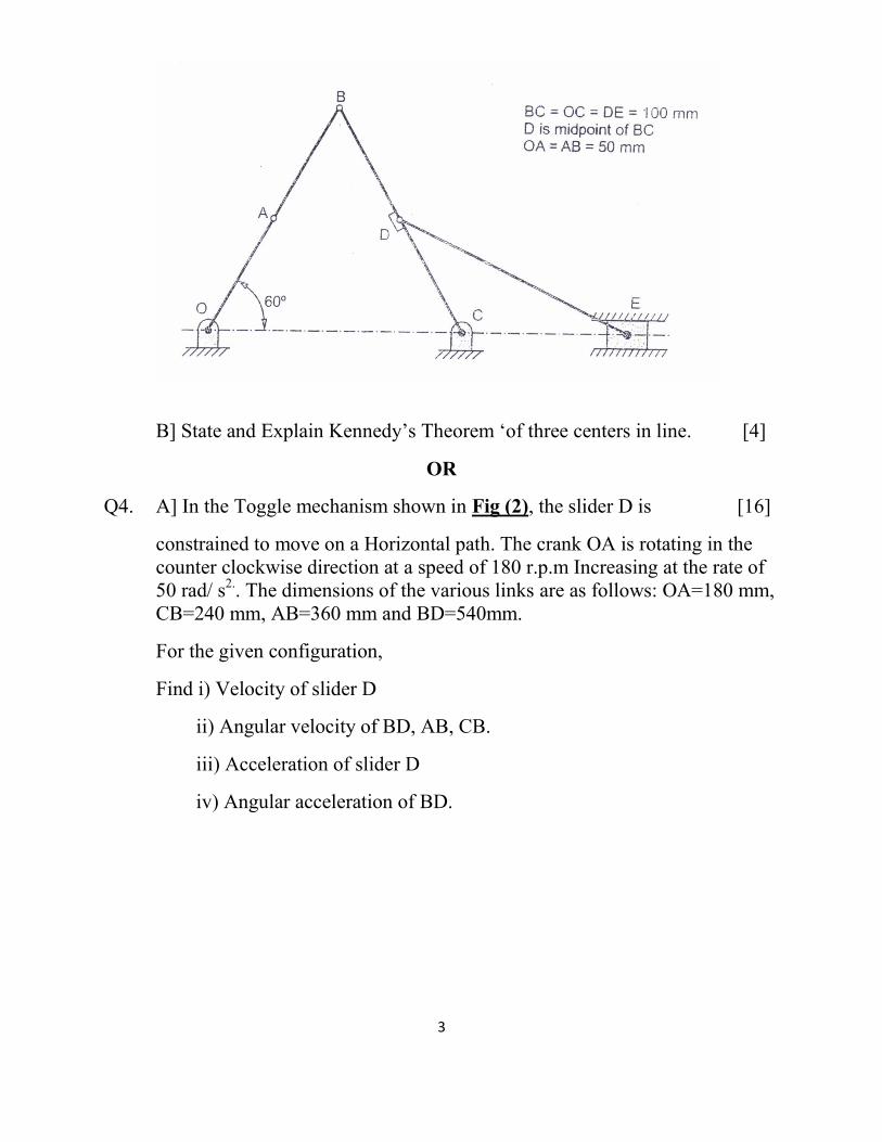
Q3. A) Fig (1) Shows mechanism in which crank OA is rotating clockwise [12]
at 240 rpm. At the instant Shown, locate all ICRs for the mechanism and
find the velocity of slider E as well as the angular velocity of the link BC
using ICR method.
BC= OC=DE= 100mm
D is a midpoint of BC.
OA =AB=50mm.
Fig (1)
3
B] State and Explain Kennedy’s Theorem ‘of three centers in line. [4]
OR
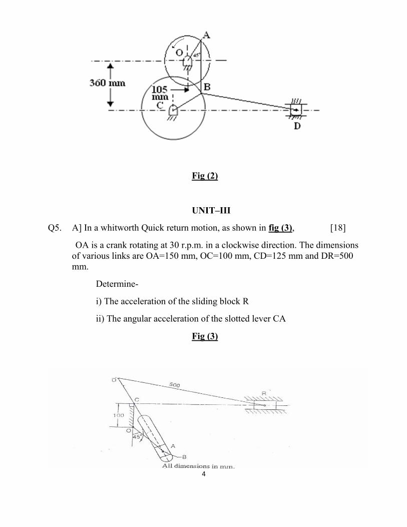
Q4. A] In the Toggle mechanism shown in Fig (2), the slider D is [16]
constrained to move on a Horizontal path. The crank OA is rotating in the counter clockwise direction at a speed of 180 r.p.m Increasing at the rate of 50 rad/ s2.. The dimensions of the various links are as follows: OA=180 mm, CB=240 mm, AB=360 mm and BD=540mm.
For the given configuration,
Find i) Velocity of slider D
ii) Angular velocity of BD, AB, CB.
iii) Acceleration of slider D
iv) Angular acceleration of BD.
4
Fig (2)
UNIT–III
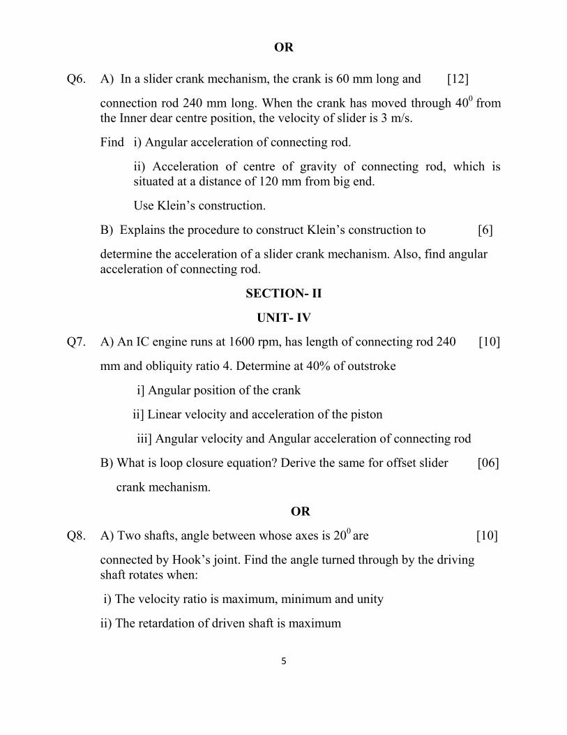
Q5. A] In a whitworth Quick return motion, as shown in fig (3), [18]
OA is a crank rotating at 30 r.p.m. in a clockwise direction. The dimensions of various links are OA=150 mm, OC=100 mm, CD=125 mm and DR=500 mm.
Determine-
i) The acceleration of the sliding block R
ii) The angular acceleration of the slotted lever CA
Fig (3)
5
OR
Q6. A) In a slider crank mechanism, the crank is 60 mm long and [12]
connection rod 240 mm long. When the crank has moved through 400 from the Inner dear centre position, the velocity of slider is 3 m/s.
Find i) Angular acceleration of connecting rod.
ii) Acceleration of centre of gravity of connecting rod, which is situated at a distance of 120 mm from big end.
Use Klein’s construction.
B) Explains the procedure to construct Klein’s construction to [6]
determine the acceleration of a slider crank mechanism. Also, find angular acceleration of connecting rod.
SECTION- II
UNIT- IV
Q7. A) An IC engine runs at 1600 rpm, has length of connecting rod 240 [10]
mm and obliquity ratio 4. Determine at 40% of outstroke
i] Angular position of the crank
ii] Linear velocity and acceleration of the piston
iii] Angular velocity and Angular acceleration of connecting rod
B) What is loop closure equation? Derive the same for offset slider [06]
crank mechanism.
OR
Q8. A) Two shafts, angle between whose axes is 200 are [10]
connected by Hook’s joint. Find the angle turned through by the driving shaft rotates when:
i) The velocity ratio is maximum, minimum and unity
ii) The retardation of driven shaft is maximum
6
iii) Draw the polar diagram representing angular velocities of driving and
driven shaft indicating the various angular positions.
B) Explain complex number method of acceleration analysis. [6]
UNIT-V
Q9. A) A four bar mechanism is used to generate the function y=x2 +4x, [12]
for the range 1 x 3. Find the three precision positions from chebychev spacing, if the initial values of the crank angle and follower angle are 30°
and 1500 respectively. Take = = 900 . Find the corresponding values of x, y, and . Also find the dimensions of other link, if the grounded link is 100 mm and input link is 40 mm. Use inversion method.
B] Explain [6]
i] Number Synthesis
ii] Type Synthesis
iii] Dimensional Synthesis
OR
Q10. A) Explain following terms [8]
i) Function Generation
ii) Path Generation
iii) Precision Points
iv) Structural Error
B) Design a four bar mechanism with input link ‘a ‘and output link ‘c’ [10]
angles and for three successive positions are as follows
1 = 200 1 = 350
2 = 350 2 = 450
3 = 500 3 = 600
7
If the length of grounded link is 40 mm, using Freudenstein’s equation find out other link lengths to satisfy the given positional conditions.
UNIT-VI
Q11 A) With the help of neat sketch explain Bifilar suspension method [06]
B) Explain dynamic equivalence of two mass systems, for a connecting rod of an IC engine having mass ‘m’ and radius of gyration ‘k’. Obtain a two mass dynamically equivalent system, having one of the two masses at the small end. How dynamical equivalence is achieved if it is required that the other mass located at the big end [10]
OR
Q12. A) An IC engine has a stroke of 100 mm and bore of 80 mm. [10]
The connecting rod is 160 mm between centers and has total mass of 1.3 kg. Its center of mass is 130 mm away from small end center and radius of gyration about the mass center is 75 mm. The reciprocating mass is 1.8 kg. Determine magnitude of resultant forces on the crank pin, neglecting friction and gravity, when the crank is 300 after the TDC position and rotating at 1600 rpm clockwise. The gas pressure on the piston is 2 N/mm2
B) Derive frequency equation of compound pendulum [6]
University of Pune[4362]-118
S. E. Examination-2013Mech/ Mech SW/ Auto
ELECTRICAL TECHNOLOGY (2008 Pattern)
[Time : 3 Hours] [Max. Marks : 100]Instructions :
(1) Answer Q1 or Q2, Q3 or Q4 , Q5 or Q6 from section 1 andQ7 or Q8, Q9 or Q10, Q11 or Q12 from section II .
(2) Answers to the two sections should be written in separate answer-books.
(3) Black figures to the right indicate full marks.(4) Neat diagrams must be drawn wherever necessary.(5) Use of non-programmable pocket size scientific
calculator is allowed.(6) Assume suitable data, if necessary.
SECTION IQ1 a) Show that in the two-wattmeter method of power measurement, the power consumed by a balanced 3-ph. Load with lagging power factor of 0.866 equals the sum of the two wattmeter readings. 6
b) What are requirements of a good lighting scheme? State two examples of special purpose lighting. 6
c) Explain use of CT and PT for measurement of power in single phase system with the help of neat sketch. 6
OR
Q2 a) Explain one wattmeter method for measurement of reactive power in three-phase circuit withthe help of suitable sketch and phase or diagram. 6
b)What are objectives of Tariff? Explain TOD tariff. 6
c) The power in a 3-phase circuit is measured by two wattmeters. If the total power is 100 KW and power factor is 0.66 leading; what will be the reading of each wattmeter? For what p.f. will one of the wattmeter read zero? 6
Q3 a) Derive an expression for the torque developed by an induction motor under running conditions. Hence obtain the condition for maximum torque developed. 8
b) Discuss the role of various components of typical distribution transformer substation with the help of single line diagram. Also write the specifications of a distribution transformer. 8OR
Q4 a) Discuss three phase transformer connections with the help of suitable diagrams. Comment on their possible applications. 8
b) The power input to the rotor of a 440V, 50Hz, 6-pole, 3-phase induction motor is 100 KW. The rotor electromotive force is observed to make 120 cycles per minute. Calculate: 8i) rotor speedii) mechanical power developediii) rotor copper loss per phaseiv) rotor resistance per phase if rotor current is 60 A.
Q5 a) What is principle of working of split-phase induction motor? Explain the operation of capacitor start motor and state its applications. 8
b) Discuss the concept of synchronous reactance and synchronous impedance in case of an alternator on load. Draw and explain phasor diagram of a loaded alternator. 8
OR Q6 a) Explain construction and working of shaded pole type induction motor with the help of suitable sketches. State its applications. 8
b) A 3-phase, 600 KVA alternator has a rated terminal voltage of 3300V. The stator winding is star-connected and has a resistance of 0.37 Ω/phase and a synchronous reactance of 4.3 Ω/phase. Calculate the voltage regulation for full load at a power factor of (i) unity and (ii) 0.8 lagging. 8
SECTION-IIQ7 a) Explain any two types of DC motors with the help of its circuit diagram and write their Voltage and Current relations. 6
b) Write short Note on 12i) Stepper Motorii) A.C. Servo Motor
ORQ8 a) A 250 Volts D.C. Shunt motor is running at a Speed of 1000 r.p.m. and drawing 8 amps. Current at NO LOAD. Motor armature resistance Ra=0.2 ohms and Field resistance Rsh=250ohms. Calculate the speed when motor is taking a Current of 51 amps. Assume constant flux. 6
b) Explain construction of D.C. motor with heat sketch. 6
c) Explain the significance of the name ‘Universal Motor’ and which motor can be developed as 6 Universal motor some design changes and How?
Q9a) Enlist various turn ON methods of SCR and explain best suited method for operation. 6
b) Explain V-I characteristics of TRIAC 6
c) Draw the Symbols of i) SCR ii)DIAC iii)MOSFET iv)IGBT 4
OR
Q10 a) Explain the construction & working of MOSFET 6
b) Draw the V-I characteristics of SCR & show Holding Current, Latching Current and on state Voltage drop of SCR on it. 6
c) State applications of TRIAC and SCR 4
Q11a) Explain the need of constant V/F ratio in the speed control of Induction motor? 6
b) Explain the importance of speed torque characteristics in the section of the drive (give suitable examples) 6
c) State any four advantages of ELECTRICAL drives 4
OR
Q12 a) Explain single phase full converter Fed D.C. drive with suitable diagrams. 6
b) Write short note on Factors governing selection of the drives. 6
c) State working principle of frequency control of three phase induction motor 4
Page 1 of 7
[Total No. of Questions: 12] [Total No. of Printed Pages: 6]
UNIVERSITY OF PUNE
[4362]-120
S. E. (Mechanical) (Sem-II) Examination - 2013
(Production Technology)(2008 Course)
[Time: 3 Hours] [Max. Marks: 100]
Instructions:
1 Answers to the two sections should be written in separate
answer-books.
2 Solve Q1 or Q2, Q3 or Q4, Q5 or Q6 from Section I and
3 Solve Q7or Q8, Q9 or Q10, Q11 or Q12 from Section II.
4 Assume suitable data, if necessary.
5 Figures to the right indicate full marks.
6 Use of logarithmic tables, slide rule, electronics pocket
calculator is allowed
7 Neat diagrams must be drawn wherever necessary.
SECTION -I
Q.1 A List out the difference between orthogonal cutting and oblique
cutting
4
Page 2 of 7
B Define tool life and mention types of tool wear 3
C Draw Merchant is Circle of forces 3
D The following equation for tool life is given for a turning operation
VT0.13 f 0.77 d0.37=C. A 70 minute tool life was obtained while
cutting at V=35 m/min. and f=0.3mm/rev and d=2mm. Determine
change in tool life if cutting speed feed and depth of cut are
increased by 20% individually and also taken together.
6
OR
Q.2 A In orthogonal cutting operation the feed is 0.1 mm and chip
thickness is 0.25mm. The cutting force is 1300 N and thrust force
is 700 N. The rake angle of tool is 10°Find i) Coefficient of friction
ii) Shear force and normal force on shear plane
iii) Shear strain iv) Specific power consumption in
𝑘𝑤−𝑚𝑖𝑛
𝑐𝑚 3 (width=3mm,𝑉𝑐 = 50𝑚 𝑚𝑖𝑛 )
8
Page 3 of 7
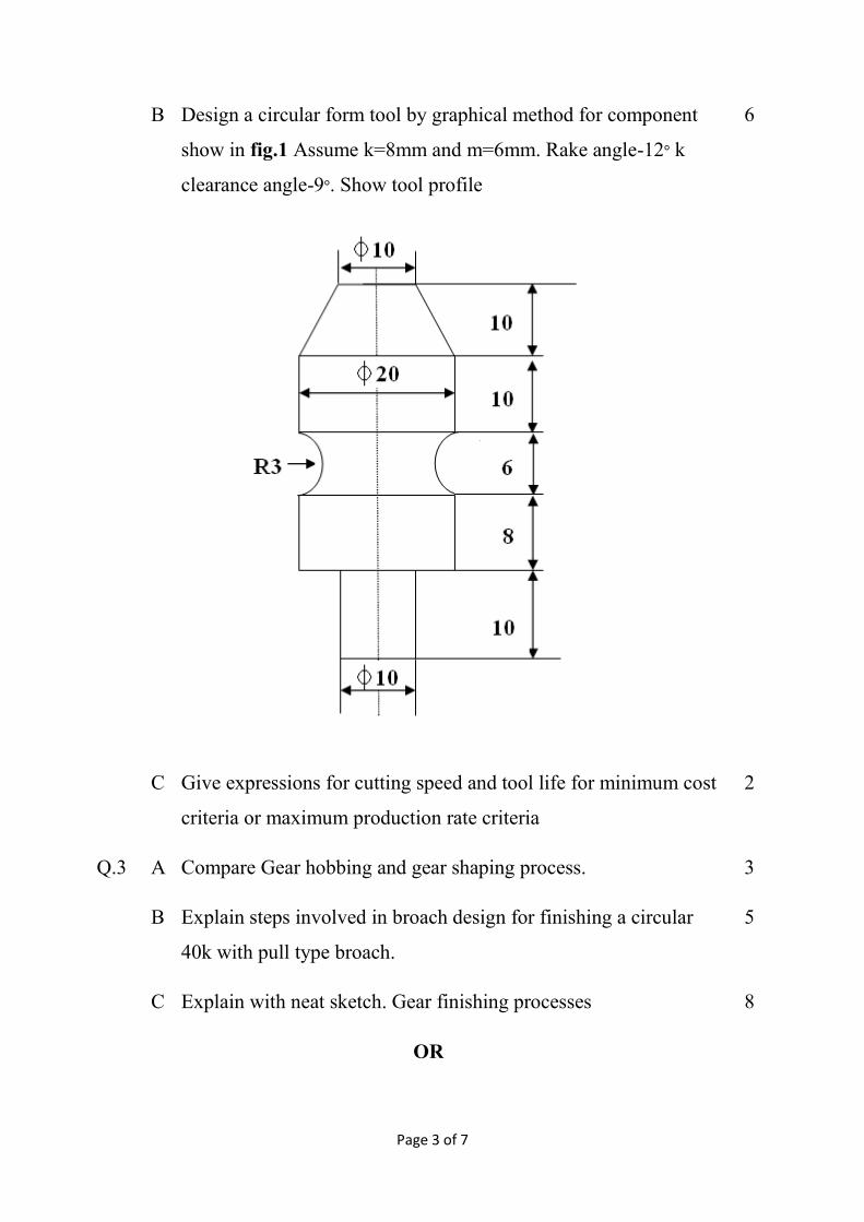
B Design a circular form tool by graphical method for component
show in fig.1 Assume k=8mm and m=6mm. Rake angle-12° k
clearance angle-9°. Show tool profile
6
C Give expressions for cutting speed and tool life for minimum cost
criteria or maximum production rate criteria
2
Q.3 A Compare Gear hobbing and gear shaping process. 3
B Explain steps involved in broach design for finishing a circular
40k with pull type broach.
5
C Explain with neat sketch. Gear finishing processes 8
OR
Page 4 of 7
Q.4 A Explain gear hobbing process with neat sketch along with its
advantages & limitation.
8
B Explain the various types of broaching methods 8
Q.5 A Explain with block diagrams difference between NC, CNC and
DNC
6
B Explain meaning of 2 axis, 3 axis, 5 axis CNC machines 2
C Explain following codes M08, G84,G91,M03,M05,G01 6
D Write a short note on FMS 4
OR
Q.6 A Explain difference between open loop and close loop system with
sketches
4
B Explain with neat sketch NC motion control system 6
C Write short notes on any two
i. DNC
ii. FMS
iii. Machining Centers
8
SECTION II
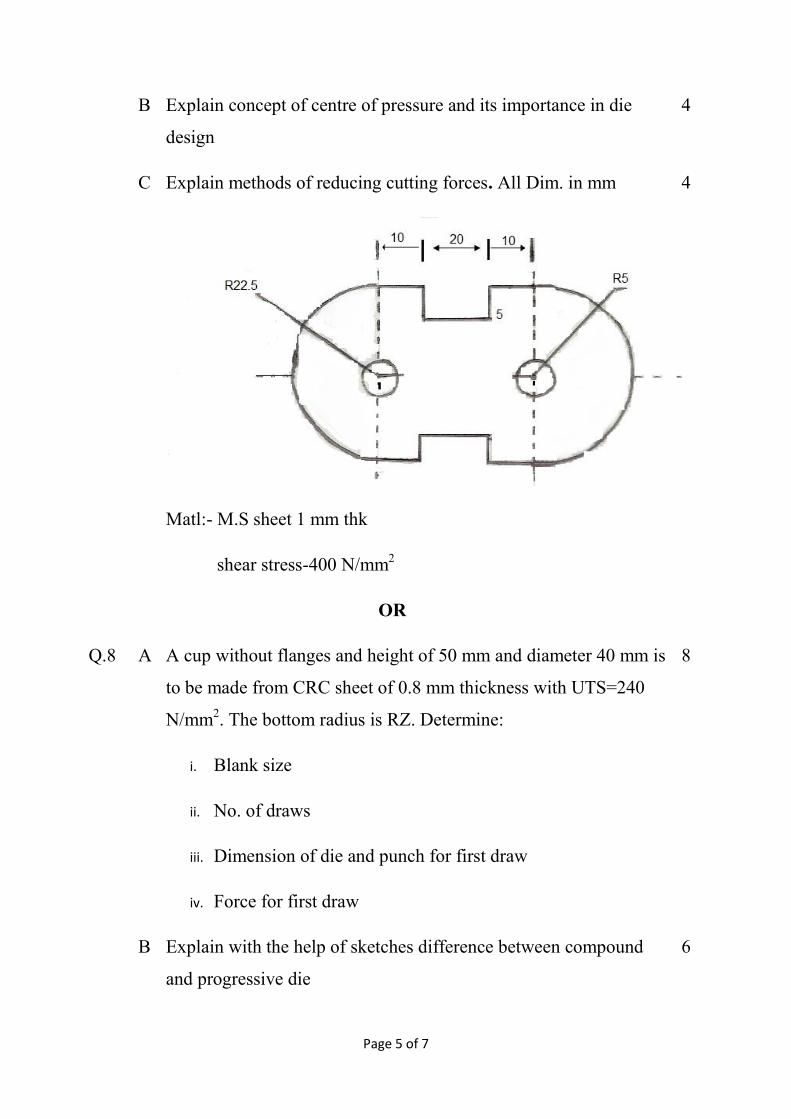
Q.7 A For the component show in fig.2
i. Draw two strip layout and find out material utilization
ii. find out the press tonnage
8
Page 5 of 7
B Explain concept of centre of pressure and its importance in die
design
4
C Explain methods of reducing cutting forces. All Dim. in mm
Matl:- M.S sheet 1 mm thk
shear stress-400 N/mm2
4
OR
Q.8 A A cup without flanges and height of 50 mm and diameter 40 mm is
to be made from CRC sheet of 0.8 mm thickness with UTS=240
N/mm2. The bottom radius is RZ. Determine:
i. Blank size
ii. No. of draws
iii. Dimension of die and punch for first draw
iv. Force for first draw
8
B Explain with the help of sketches difference between compound
and progressive die
6
Page 6 of 7
C Why pilots are coed in progressive die? 2
Q.9 A Explain with neat sketch electro-discharge machining (EDM) with
its advantages, limitations and applications
8
B What are the common gases used in LASER? 2
C Explain Electron Beam Machining (EBM) in detail with neat
sketch
6
OR
Q.10 A Compare characteristics of conventional and non-conventional
machining methods
4
B Explain with neat sketch Electro Chemical Process with its
advantages limitations and applications
8
C i. Explain principle of Abrasive jet machining (AJM) 4
OR
ii. Explain factors affecting material removal rate (MRR) in
AJM
Q.1
1
A Explain with sketch the redundant locator 3
B Why adjustable locators are needed? 2
C Explain with sketch working of Turn-over type of Jig. 7
D Explain with sketch the slip bush assembly. 4
E What is fool proofing in designing locating system 2
OR
Page 7 of 7
Q.12 A What is 3:2:1 location principle? Explain with suitable sketches. 6
B Explain the clamping principles used in design of Jigs & fixtures 4
C State various types of clamping devices used in jigs & fixtures.