BESCHREIBUNG........................................................................DRUCKLUFT - KUGELVIBRATOREN S.........................................PNEUMATISCHE DRUCKLUFT - TURBINEN VIBRATOREN T.........DRUCKLUFT - ROLLEN VIBRATOREN R.....................................KONSTRUKTIONSDATEN............................................................ZWEK UND BEDEUTUNG DES HANDBUCHS...............................KONFORMITÄTSBESCEINIGUNG ................................................HINWEISE.....................................................................................ANGABEN ZUM GEBRAUCH.......................................................EINSATZEINSCHRÄNKUNGEN.....................................................GARANTIEBEDINGUNGEN...........................................................TRANSPORT UND PACKUNG......................................................LAGERHALTUNG.........................................................................EINBAU........................................................................................WARTUNG...................................................................................RESTRISIKEN...............................................................................BETRIEBSSTÕRUNGEN UND ABHILFE........................................VERSCHROTTUNG - RÜCKGABE BEAUTEIL..............................
2MAINTENANCE CATALOGUE
DESCRIPTION............................................................................PNEUMATIC BALL VIBRATORS S.............................................PNEUMATIC TURBINE VIBRATORS T.........................................PNEUMATIC ROLL VIBRATORS R.............................................MANUFACTURING DATA...........................................................SCOPE AND IMPORTANCE OF THE MANUAL............................CERTIFICATE OF CONFORMITY ...............................................WARNINGS...............................................................................INDICATIONS FOR USE.............................................................OPERATING CONDITIONS..........................................................WARRANTY CONDITIONS........................................................TRANSPORT AND PACKING......................................................STORAGE ................................................................................INSTALLATION..........................................................................MAINTENANCE..........................................................................RESIDUAL RISKS......................................................................FAULT FINDING..........................................................................SCRAPPING - RETURNING THE COMPONENT............................
DESCRIPTION...........................................................................VIBRATEUR PNEUMATIQUES A BILLE S....................................VIBRATEURS PNEUMATIQUES A TURBINE T.............................VIBRATEURS PNEUMATIQUES A ROULEX R.............................DONNÉES CONSTRUCTIVES....................................................BUT ET IMPORTANCE DU MANUEL...........................................CERTIFICAT DE CONFORMITÉ ..................................................RECOMMANDATIONS...............................................................INDICATIONS POUR L’UTILISATION...........................................LIMITES DE EMPLOI..................................................................CONDITIONS DE GARANTIE.....................................................TRANSPORT EMBALLAGE......................................................EMMAGASINAGE ....................................................................INSTALLATION.........................................................................ENTRETIEN...............................................................................RISQUES RESIDUELS...............................................................INCONVENIENTS ET SOLUTIONS............................................DEMANTELEMENT - RESTITUTION COMPOSANT......................
CATALOGO DI MANUTENZIONE
DESCRIZIONE............................................................................VIBRATORI PNEUMATICI A SFERA TIPO S...................................VIBRATORI PNEUMATICI A TURBINA T.........................................VIBRATORI PNEUMATICI A RULLI R.............................................DATI COSTRUZIONE....................................................................SCOPO E IMPORTANZA DEL MANUALE.....................................ATTESTATO DI CONFORMITA’ ....................................................AVVERTENZE..............................................................................INDICAZIONI PER L’USO..............................................................LIMITI DI IMPIEGO.........................................................................CONDIZIONI DI GARANZIA..........................................................TRASPORTO IMBALLO...............................................................IMMAGAZZINAGGIO ..................................................................INSTALLAZIONE..........................................................................MANUTENZIONE..........................................................................RISCHI RESIDUI............................................................................INCONVENIENTI E SOLUZIONI.....................................................ROTTAMAZIONE - RESO COMPONENTE.....................................
NOTE GENERALII vibratori sono costruiti in con-formità alla norma 89/392/CE suimacchinari. Si è in particolaretenuto conto di quanto stabilitodalle norme EN 292, parte 1 eparte 2.I vibratori producono vibrazionimultidirezionali. Sono impiegatiper mantenere un flusso co-stante nelle tramogge e nei sili,per attivare dosatori, vagli e ta-vole vibranti e in generale perdistaccare, trasportare, compat-tare e separare materiale sfusoe per ridurre l’attrito.I vibratori sono perfettamenteindicati per l’impiego nell’industriaalimentare, in atmosfera esplo-siva, in ambienti umidi e all’ester-no. La frequenza delle vibrazio-ni e la forza centrifuga sono de-terminati dalla pressione d’eser-cizio.
REMARQUES GÉNÉRALESLes vibrateurs S, OT et OR cor-respondent à la directive Machi-nes 89/392/C.E.E. Il a été tenucompte des normes EN 292, l’ et1-2 parties. Ces vibrateurs gé-nèrent des vibrations multidirec-tionnelles. Ils sont utilisés pourle vidage de silos, l’entraînementde goulottes l’activation de cou-loirs vibrants, de tamis et de ta-bles vibrantes et, d’une façcongenerale en général, pour ,dé-colmater, transporter, compac-ter, et séparer les matières envrac et réduire les frictions. Siles prescriptions d’emploi élabo-rées par l’utilisateur sont respec-tées, ils peuvent être mis enoeuvre pour la fabrication dedenrées alimentaires ainsi qu’enmilieu explosif ou humide. Lesvibrateurs peuvent aussi fonc-tionner à l’extérieur. La fréquen-ce et la force centrifuge sont dé-terminées par la pression deservice.
REMARQUEPour les entretiens extraordinai-res s’adresser exclusivement à:
ALLGEMEINESDie Vibratoren der Serie S, ORund OT entsprechen der EU-Ma-schinenrichtlinie 89/392/EWGund insbesondere den NormenEN 292, Teil 1 und 2.Dieser Vibratortyp erzeugt un-gerichtete Schwingungen.Sie werden zur Behälterentlee-rung, als Antriebe für Rinnen,Siebe und Vibrationstische ein-gesetzt und im allgemeinen zumLösen, Fördern, Verdichten undTrennen von Schüttgütern undzur Reduzierung von Reibung.Unter Beachtung der Bedie-nungsvorschriften des Betrei-bers können diese Vibratorenauch für die Nahrungsmittelher-stellung sowie in EX- und Naß-bereichen eingesetzt werden.Ein Einsatz der Vibratoren imFreien ist möglich.Frequenz und die davon abhän-gige Zentrifugalkraft werdendurch den Betriebsdruck be-stimmt.
GENERAL NOTESThe vibrators are made in ac-cordance with the EC machineregulation 89/392/E1EC. Thestandards EN 292, part 1 and part2 have been particularly ob-served.The vibrators produce non-di-rected vibrations. They are usedto keep a constant flow in hop-pers and silo’s, to drive chutesand are also used in screensand vibrating tables. Generallyfor loosening, conveying andseparating of bulk materials andfor the reduction of friction.The vibrators are ideal for use inthe food industry, explosive at-mosphere’s, wet environment’sand outside. The frequency andthe centrifugal force are deter-mined by the operating pressure.
Indicazioni generali- I vibratori a sfera serie “S”
sono costituiti da un corpo inalluminio anodizzato all’internodel quale ruota una sfera in ac-ciaio temprato su una sede diacciaio temprato antiusura. Il vi-bratore “S” genera vibrazionidi piccola ampiezza di sposta-mento.
Esempi di applicazione- Separazione, trasporto, com-
pattazione materiali.- Sgorgo di sili, tramogge, vagli,
ecc.- Pulizia filtri.- Su catene di trasporto (per es.
barattoli, bottiglie, ecc.) facili-tano il deflusso ed eliminano iproblemi di bloccaggio.
PERFORMANCE DATA - LEISTUNGSDATEN- PERFORMANCE - PRESTAZIONI
General indications- Ball vibrators “S” consist of an
anodized aluminium body in-side which a tempered steel ballrotates on an anti-wear tem-pered steel seating. Vibrator“S” generates vibrations ofsmall amplitudes.
Examples of application- Separation, transport, com-
pacting of materials.- Gushing of material from of si-
amples cans, bottles, etc.) theyfacilitate the flow and eliminateproblems of blockage.
Maximum operating temper-ature:- 20°C / +200°C
Allgemeine Angaben- Die Kugelvibratoren Serie „S”
bestehen aus einem Gehäuseaus eloxiertem Aluminium, in-nerhalb dessen sich eine Ku-gel aus gehärtetem Stahl in ei-nem Sitz aus gehärtetem ver-schleißfestem Stahl dreht. DerVibrator „S” erzeugt Schwin-gungen kleinern Ausmaßes.
freimachen.- Filter reinigen.- Auf Förderketten (z.B. Dosen,
Flaschen, etc.) vereinfachensie den Materialfluss und be-seitigen Probleme mit etwaigenBlockierungen.
Max. Betriebstemperatur-20°C / +200°C
Indications générales- Les vibrateurs à bille de la sé-
rie “S” sont constitués d’uncorps en aluminium anodisédans lequel tourne une bille enacier trempé sur un siège enacier trempé anti-usure. Le vi-brateur “S” produit des vibra-tions de petite amplitude.
pactage de produits- Débourrage de silos, trémie, ta-
mis, etc.- Nettoyage des filtres.- Sur les chaînes de transport
(par ex. boîtes, bouteilles, etc.)ils facilitent l’écoulement et éli-minent les problèmes de blo-cage.
Température maximum deservice-20°C / +200°C
-
-
-
-
2
OL.2000 EX M.
06.04
5
S
OT
OR
PNEUMATIC TURBINE VIBRATORS “T”
PNEUMATISCHE DRUCKLUFT - TURBINEN-VIBRATOREN “T”
VIBRATEURS PNEUMATIQUES A TURBINE “T”
VIBRATORI PNEUMATICI A TURBINA “T”
Indicazioni generali- La vibrazione è generata da
una turbina sbilanciata che girasu 2 cuscinetti a sfera ad altavelocità.
- I vibratori a turbina OT genera-no un elevato momento di lavo-ro ed una alta frequenza di vi-brazione.
- Le vibrazioni hanno una note-vole ampiezza anche a bassepressioni di esercizio.
Esempi di applicazione- Industria alimentare e farma-
ceutica.- Sili e tramogge.- Vagli.Temperaturamassima d’esercizio- 20°C / +120°C
Indications générales- la vibration est engendrée par
une turbine déséquilibrée mon-tée sur 2 roulements à bille àhaute vitesse.
- Les vibrateur à turbine OT en-gendrent un couple élevé et unehaute fréquence de vibration.
- Les vibrations ont une amplitu-de considérable même à bas-se pression d’exercice.
Exemple d’application- Industries alimentaire et phar-
maceutique- Trémies et d’autres récipients.- Tamis.Température maximum deservice-20°C / +120°C
Allgemeines- Die Vibration wird durch eine
exzentrisch angeordnete Tur-bine erzeugt, die sich mit ho-her Geschwindigkeit auf 2 Ku-gellagern dreht.
- Zwei überdimensionierte, fürden Dauereinsatz bei hohenDrehzahlen geeignete Lagergarantieren einen hohen Wir-kungsgrad und ermöglichenden Einsatz ungeölter Druck-luft.
- OT Vibratoren sind vollkommenwartungsfrei und zeichnensich aus durch hohe Drehzah-len bei gleichzeitig geringemLuftverbrauch.
Anwendungsbeispiele- Nahrungsmittel und Pharmain-
dustrie.- Trichter und Behälterbau.- Siebanlagen.Max. Betriebstemperatur-20°C / +120°C
General indications- Vibration is generated by a
strongly unbalanced turbinewhich rotates on two high-speed ball bearings.
- OT vibrators develop a highwork moment and a high vibra-tion frequency.
- Vibrations present a large am-litude even with low operatingpressure.
Examples of application- Food and Pharmacentical indu-
stries.- Bins and hoppers.- Goreens.Maximum operatingtemperature :- 20°C / +120°C
N.B.: dati rilevati utilizzando unbanco vibrante a molle, in mododa simulare perfettamente lamaggior parte delle possibili ap-plicazioni. Frequenza e forzacentriga saranno maggiori appli-cando il vibratore su strutture piùrigide.
Per l’azionamento occorro-no una elettrovalvola a 2/2 vieed aria filtrata.
PERFORMANCE DATA - LEISTUNGSDATEN- PERFORMANCE - PRESTAZIONI
N.B.: les données ont été rele-vées sur un banc vibrant à res-sorts, de manière à simuler par-faitement la plupart des applica-tions possibles. La frequence etla force centrifuge seront plusgrandes où le vibrateur est ap-pliqué sur une structure plus ri-gide.
Pour l’actionnement on abesoin d’une èlectrovanne à2/2 voies et d’air filtré
N.B.: daten wurden auf einemgefederten Rütteltisch ermittelt,aud dem die Mehrzahl der mög-lichen Anwendungen perfekt si-muliert wurde. Frequenz undZentrifugalkraft nehmen bei ei-ner Befestigung des Vibratorsauf weniger elastischen Unter-lagen zu.
Zur Betätigung ist ein 2/2Wege-Ventil und gefilterDruckluft erforderlich
N.B.: data abtained from a vibrat-ing table supported by springsthat perfectly simulates the ma-jor part of the applications pos-sible. Frequency and centrifuglaforce increase when the vibra-tor is applied to more rigid struc-tures.
For activation a 2/2 way elec-trovalve and filtered com-pressed air are required.
-
-
-
-
2
OL.2000 EX M.
06.04
7
S
OT
OR
PNEUMATIC ROLL VIBRATORS “R”
DRUCKLUFT - ROLLEN VIBRATOREN “R”
VIBRATEURS PNEUMATIQUES A ROULEX “R”
VIBRATORI PNEUMATICI A RULLI “R”
Indicazioni generali- I vibratori a rulli serie “R” sono co-
stituiti da un corpo in alluminio ano-dizzato all’interno del quale ruota unrullo in acciaio temprato su pista inghisa.
- La vibrazione è generata da un ro-tore che compie un movimento epi-cicloidale all’interno di una pista diacciaio.
- I vibratori a rullo OR generano unafrequenza molto elevata con unconsumo ridotto, in relazione allaforza resa.
Esempi di applicazione- Sili e tramogge- Forme- Compattazione- SeparazioneTemperaturamassima d’esercizio0°C / +200°C
Indications générales- Les vibrateurs à rouleaux, série “R”,
comprennent un corps en aluminiumanodisé avec un rouleau en aciertrempé sur piste en fonte roulant àl’interieur.
- La vibration est engendrée par unrouleau qui accomplit un mouve-ment épicycloïdal à l’intérieur d’unepiste en acier.
- Les vibrateurs à rouleau OR, en-gendrent une fréquence trés éle-vée avec une consommation d’airréduite par rapport à la force déve-loppée.
Exemple d’application- Trémies et d’autres récipients- Moules- Compactage- SéparationTempérature maximum de service0°C / +200°C
Allgemeines- Die Rollen „R“ Rüttler bestehen aus
einemm Körper aus eloxiertem Alu-minium, innerhalb mit einer Rolleaus gehärtetem Stahl, die auf Guss-eisen Laufbahn rotiert.
- Die Vibration wird durch eine Rolleerzeugt, die innerhalb eines speziellgehärteten Stahlringes eine epizyk-lische Bewegung beschreibt.
- OR Vibratoren entwickeln hoheFliehkräfte und laufen in jeder Ein-baulage sicher an.
Anwendungsbeispiele- Trichter und Behälter- Gussformen- Verdichter- KlassiererMax. Betriebstemperatur0°C / +200°C
General indications- The roller vibrators series “R” are
formed by an anodized aluminiumbody inside which a hardened steelroller wheels an a cast iron race.
- Vibration is generated by a rotorwhich describes an epicycloidalmovement inside a steel race.
- The OR vibrators generate a veryhigh frequency with low consump-tion as compared to the force giv-en.
Examples of application- Bins and hoppers- Moulding dies- Compacting- SeparationMaximum operatingtemperature0°C / +200°C
PERFORMANCE DATA - LEISTUNGSDATEN- PERFORMANCE - PRESTAZIONI
N.B.: dati rilevati utilizzando un ban-co vibrante a molle, in modo da simu-lare perfettamente la maggior partedelle possibili applicazioni. Frequenzae forza centriga saranno maggiori ap-plicando il vibratore su strutture piùrigide.
Per l’azionamento occorrono unaelettrovalvola a 2/2 vie ed aria fil-trata.
N.B.: les données ont été relevéessur un banc vibrant à ressorts, demanière à simuler parfaitement la plu-part des applications possibles. Lafrequence et la force centrifuge se-ront plus grandes où le vibrateur estappliqué sur une structure plus rigide.
Pour l’actionnement on a besoind’une èlectrovanne à 2/2 voies etd’air filtré
N.B.: daten wurden auf einem gefe-derten Rütteltisch ermittelt, aud demdie Mehrzahl der möglichen Anwen-dungen perfekt simuliert wurde. Fre-quenz und Zentrifugalkraft nehmenbei einer Befestigung des Vibratorsauf weniger elastischen Unterlagenzu.Zur Betätigung ist ein 2/2 Wege-Ventil und gefilter Druckluft erfor-derlich
N.B.: data abtained from a vibratingtable supported by springs that per-fectly simulates the major part of theapplications possible. Frequency andcentrifugla force increase when thevibrator is applied to more rigid struc-tures.
For activation a 2/2 way electrov-alve and filtered compressed airare required.
-
-
-
-
2
OL.2000 EX M.
06.04
S
OT
OR
8
MANUFACTURING DATA
KONSTRUKTIONSDATEN
DONNÉES CONSTRUCTIVES
DATI COSTRUZIONE
1) Machine code2) Machine serial number3) Assembly operator code4) Year of construction5) Group and category6) Surface Tmax
with T amb. -20 °C / +180°C
1) Maschinencode2) Serien-Nr. Maschine3) Monteur-Code4) Baujahr der Maschine5) Gruppe und Kategorie6) Tmax Oberfläche
mit T amb. -20 °C / +180°C
1) Code machine2) Matricule de la machine3) Code opérateur assembleur4) Année de fabrication machi-
ne5) Groupe et catégorie6) Tmax superficiel
avec T amb. -20 °C / +180°C
1) Codice macchina2) Numero matricola3) Codice operatore assembla-
tore4) Anno di costruzione macchi-
na5) Gruppo e categoria6) Tmax superficiale
con T amb. -20 °C / +180°C
IDENTIFICAZIONEDELCOMPONENTEPer una corretta identificazionedel componente, bisogna fareriferimento al codice che si tro-va sulla targhetta.
N.B.: il vibratore pneumaticonon deve essere marcatoCE in quanto componente.
IDENTIFICATIONDU COMPOSANTPour identifier correctement lecomposant, faire référence aucode qui se trouve sur la plaquesignalétique.
N.B. : En tant que composantle vibrateur pneumatique neporte pas le marquage CE.
B) IDENTIFIKATIONDES BAUTEILSZur korrekten Identifikation desBauteils Bezug auf den Codenehmen, der auf dem Schildsteht.
Anm.: Der pneumatische Vi-brator darf nicht mit der CE-Kennzeichnung versehenwerden, da es sich um einBauteil handelt.
B) IDENTIFICATIONOF COMPONENTFor correct identification of thecomponent, refer to the code onthe rating plate.
NOTE: The pneumatic vibra-tor must not be CE markedsince it is a component.
Rating plate for S or OR vibrator - Schild für Vibrator S oder OR
Plaque pour vibrateur S ou OR - Targhetta per vibratore S e OR
Rating plate for OT vibrator- Schild für Vibrator OT
Plaque pour vibrateur OT - Targhetta per vibratore OT
1) Machine code2) Machine serial number3) Assembly operator code4) Year of construction5) Group and category6) Surface Tmax
with T amb. -20 °C / +120°C
1) Maschinencode2) Serien-Nr. Maschine3) Monteur-Code4) Baujahr der Maschine5) Gruppe und Kategorie6) Tmax Oberfläche
mit T amb. -20 °C / +120°C
1) Code machine2) Matricule de la machine3) Code opérateur assembleur4) Année de fabrication machi-
ne5) Groupe et catégorie6) Tmax superficiel
avec T amb. -20 °C / +120°C
1) Codice macchina2) Numero matricola3) Codice operatore assembla-
tore4) Anno di costruzione macchi-
na5) Gruppo e categoria6) Tmax superficiale
con T amb. -20 °C / +120°C
ex
≤ ≤
ex
≤ ≤
-
-
-
-
2
OL.2000 EX M.
06.04
9
S
OT
OR
SCOPE AND IMPORTANCE OF THE MANUAL
ZWECK UND BEDEUTUNG DES HANDBUCHS
BUT ET IMPORTANCE DU MANUEL
SCOPO E IMPORTANZA DEL MANUALE
Il presente manuale, redatto dal co-struttore, è parte integrante del vi-bratore pneumatico S/OR/OT; cometale deve assolutamente seguire ilfiltro fino al suo smantellamento edessere facilmente reperibile per unarapida consultazione da parte deglioperatori interessati e della direzionelavori del cantiere. In caso di cambiodi proprietà della macchina il manualedeve essere consegnato alla nuovaproprietà. Prima di eseguire qualsiasioperazione con, o sul vibratore pneu-matico ; il personale interessato deveassolutamente ed obbligatoriamenteaver letto con la massima attenzioneil presente manuale. Qualora il ma-nuale venga smarrito, sgualcito e taleda non essere completamente leggi-bile, si deve scaricare una nuovacopia dal sito internet della OLI s.r.l everificarne la data dell’ultimo aggior-namento. Il presente manuale forni-sce avvertenze ed indicazioni relati-ve alle norme di sicurezza per la pre-venzione degli infortuni sul lavoro.Vanno comunque, ed in ogni caso,osservate con il massimo scrupoloda parte dei vari operatori le norme disicurezza poste a loro carico dalle vi-genti normative.Eventuali modifiche delle norme disicurezza che nel tempo dovesseroaver luogo dovranno essere recepiteed attuate.
Ferme restando le caratteristiche es-senziali delle macchine descritte, ilcostruttore si riserva il diritto di ap-portare le eventuali modifiche di or-gani, dettagli ed accessori che riterràconvenienti per il miglioramento delprodotto, o per esigenze di caratterecostruttivo o commerciale, in qualun-que momento e senza impegnarsi adaggiornare tempestivamente questapubblicazione.La versione sempre aggiornata delpresente catalogo è reperibile sul sitointernet www.olivibra.it
ATTESTATO DI CONFORMITA’
L'apparecchiatura è accompagnata dauna dichiarazione di conformità alledirettive vigenti, ma, in quanto com-ponente da integrarsi in un impiantocompleto, la sua sicurezza è legata alrispetto di tutte le direttive applicabilinell'assemblamento della macchinafinale.Ogni utilizzo improprio del vibratorepneumatico senza seguire le indica-zioni del presente manuale solleveràil costruttore da ogni responsabilitàinerenti ad un cattivo funzionamentodel vibratore pneumatico stesso.Trattandosi di materia in forte evolu-zione tecnica e normativa, il costrut-tore si riserva di adeguare con lamassima celerità i propri manufatti atutte le conoscenze tecnologiche e lenorme ufficiali applicabili (EN, UNI)che di volta in volta si rendesserodisponibili.
This manual, prepared by the manu-facturer, forms an integral part ofthe pneumatic vibrator S/OR/OT sup-ply. It must therefore accompany thefilter right up to its final scrapping,and must be available ready at handfor quick consultation by the opera-tors concerned and those in chargeof operations at the work site. If themachine changes hands, this manu-al must be handed over to the newowner. Before carrying out any oper-ation on or using the pneumatic vi-brator, the personnel concerned musthave read this manual carefully andcompletely. If the manual is lost, orin such a condition as to make it il-legible, download a new copy fromthe OLI s.r.l internet site, and checkthe date of the last revision. Thismanual provides warnings and indi-cations concerning the safety regu-lations for preventing accidents atthe work site. However, the opera-tors MUST scrupulously follow thesafety regulations meant for themaccording to the existing legislation.Modifications to the safety regula-tions made over time must be inte-grated and implemented.
With the basic features of the ma-chines as described, the Manufac-turer reserves every right to makemodifications to parts, details andaccessories considered to be neces-sary for improving the product fordesign or commercial reasons, at anytime without any obligation to updatethe publication imme-diately.The latest version of the present cat-alogue is available underwww.olivibra.it
CERTIFICATE OF CONFORMITY
The equipment is accompanied by adeclaration of conformity to existingregulations, but, since it is a compo-nent to be integrated into a systemor plant, its safety is connected tocompliance with all the directivesapplicable in final assembly of themachine.Improper use of the pneumatic vi-brator without following the instruc-tions in this manual frees the Manu-facturer of all responsibility for poorworking of the pneumatic vibrator.As this is a subject in the process ofsignificant technical and normativeevolution, the Manufacturer reservesthe right to upgrade its products asfast as possible with all the techno-logical know-how and official stand-ards applicable (EN, UNI) which areavailable at the time.
Dieses Handbuch, das vom Herstel-ler erstellt wurde, ist integrierenderTeil des Druckluft Vibrator S/OR/OT.Daher muss es unbedingt dem Filterfolgen, bis er demontiert wird, undleicht zu finden sein, wenn der Bedie-ner oder die Baustellenleitung in ihmnachschlagen wollen. Bei einem Be-sitzerwechsel des Gerätes muss dasHandbuch dem neuen Besitzer aus-gehändigt wer-den. Bevor das Be-triebspersonal irgendwelche Arbeitenan oder mit Druckluft Vibrator aus-führt, muss es dieses Handbuch un-bedingt mit großer Aufmerksamkeitdurchgelesen haben. Falls das Hand-buch verloren geht oder unleserlichwird, kann man sich eine neue Kopievon den Internetseiten des Herstel-lers OLI s.r.l herunterladen, um danndas Datum der letzten Aktualisierungdes Handbuchs zu prüfen. DiesesHandbuch liefert Hinweise und Anga-ben zu den Sicherheits- und Unfall-verhütungsbestimmungen am Ar-beitsplatz. Die Sicherheitsbestimmun-gen, die laut der geltenden Bestim-mungen vom Bedienungspersonal zubeachten sind, müssen auf jeden Fallimmer beachtet werden.Etwaige Änderungen der Sicherheits-bestimmungen, die im Laufe der Zeitvorgenommen werden, sind immer zuerfassen und umzusetzen.
Der Hersteller behält sich das Rechtvor, unter Beibehaltung der wesentli-chen Eigenschaften der beschriebe-nen Geräte etwaige Änderungen anOrganen, Teilen und Zubehör vorzu-nehmen, die im Zuge der Produktver-besserung erforderlich sind oder auskonstruktiven oder kommerziellenErfordernissen heraus ausgeführtwerden. Solche Änderungen könnenjederzeit vorgenommen werden undverpflichten den Hersteller nicht, die-se Veröffentlichung gleichzeitig aufden neuesten Stand zu bringen.Die letzte Version dieses Katalogssteht im Internet unterwww.olivibra.it
KONFORMITÄTSERKLÄRUNG
Das Gerät wird von einer den gelten-den Richtlinien entsprechenden Kon-formitäts-erklärung begleitet, aber alsBestandteil einer kompletten Anlageist seine Betriebs-sicherheit mit derBeachtung aller Richtlinien verbun-den, die nach dem Einbau in die Anla-ge oder Maschine anwendbar sind.Jede bestimmungswidrige Benutzungdes Druckluft Vibrator ohne Befol-gung der Angaben dieses Handbuchsentbindet den Hersteller von jeglicherHaftung hinsichtlich der fehlerhaftenFunktion des Druckluft Vibrator.Da es sich um Produkte handelt, dieeiner schnellen technischen Entwick-lung unterliegen, behält es sich derHersteller vor, die eigenen Erzeug-nisse so schnell wie möglich an alletechnologischen Erkenntnisse und dieanwendbaren offiziellen Normen (EN,UNI) anzupassen, die von Fall zu Fallerforderlich sind.
Le présent Manuel, rédigé par le cons-tructeur, fait partie intégrante de lafourniture du vibrateur pneumatiqueS/OR/OT; comme tel il doit absolu-ment suivre le filtre jusqu’à son dé-mantèlement et être à portée de lamain pour une consultation rapide dela part des opérateurs concernés etpar la direction des travaux du chan-tier. En cas de changement de pro-priété de la machine, le manuel doitêtre remis au nouveau propriétaire.Avant d’effectuer une quelconqueopération avec ou sur le vibrateurpneumatique, le personnel concernédoit absolument et obligatoirementavoir lu très attentivement le présentmanuel. Si le manuel est égaré ouabîmé de manière à ne plus être lisi-ble, une copie doit être téléchargée àpartir du site internet de OLI s.r.l envérifiant la date de la dernière mise àjour. Le présent manuel fournit lesrecommandations et les indicationsconcernant les consignes de sécuritépour la prévention contre les acci-dents du travail. Dans tous les casles consignes de sécurité conformé-ment aux normes en vigueur doiventêtre observées avec la plus grandeattention par les différents opérateurs.Les modifications éventuelles desconsignes de sécurité devront êtreadoptées et mises en oeuvre.
Les caractéristiques essen tielles desmachines décrites étant entendues,le constru cteur se réserve le droitd’ap porter à tout moment et sansengagement de mettre à jour en tempsutile cette publication, des modifica-tions aux organes, pièces et acces-soires qu’il retiendra avantageusespour l’amélioration du produit ou pourdes exigences de fabrication ou decommer cialisation.La version toujours mise à jour de cecatalogue est dis-ponible sul le siteinternet www.olivibra.it
CERTIFICAT DE CONFORMITÉ
L'appareillage est accompagné d’unedéclaration de conformité aux directi-ves en vigueur, mais en tant quecomposant devant s’intégrer dansune installation complète, sa sécuritéest étro itement lié au respect de tou-tes les directives applicables dansl’assemblage de la machine finale.Toute utilisation impropre du vibra-teur pneumatique sans suivre les in-dications du présent manuel dégagele constructeur de toutes responsabi-lités ayant trait à un mauvais fonc-tionnement du vibrateur pneumatiquelui-même.Etant donnée qu’il s’agit d’une matiè-re en forte évolution technique et ré-glementaire, le constructeur se ré-serve d’adapter avec rapidité ses pro-pres produits manufacturés à toutesles connaissances techno logiqueset les normes of ficielles applicables(EN, UNI) au fur et à mesure de leurparution.
-
-
-
-
2
OL.2000 EX M.
06.04
S
OT
OR
10
The OLI percussion guns model
S/OR/OT....ATEX (Code: SX....)
are manufactured in conformity with the following directives:
- Directive “Machines” 98/37/CE of 22nd June, 1998
- Directive “ATEX” 94/9/CE of 23rd March, 1994
The conformity has been verified according to the conditions included in the
following standard documents:
This equipment must never be put into operation before the machine or plant
into which it has been integrated has been declared in conformity with the
Directives in force.
Medolla, 1st November, 2003
OLI S.r.l.
OLI S.r.l.
Via Canalazzo, 35 – I - Medolla (MO)
ITALY
CERTIFICATE OF CONFORMITYwith the Directives of the European Union
• EN 1127-1
• EN 13463-1
• EN 292-1-2
• EN 1050
Serie S, OR, OT II 3 D 85°C (T6) X
Serie S, OR, X Tmax.=200°C (T3) Tamb. -20°C +180°C
Serie OT, X Tmax.=135°C (T4) Tamb. -20°C +120°C
CERTIFICATE OF CONFORMITY
KONFORMITÄTSBESCHEINIGUNG
CERTIFICAT DE CONFORMITÉ
ATTESTATO DI CONFORMITA’
Adriano Marchesini
(General Manager)
-
-
-
-
2
OL.2000 EX M.
06.04
11
S
OT
OR
Die Familie der pneumatischen Vibratoren OLI
Modell S/OR/OT....ATEX (Code: SX....) wurde
konstruiert und wird gefertigt in Konformität mit den folgenden Direktiven:
- Direktive “Maschinen” 98/37/CE vom 22. Juni 1998
- Direktive “ATEX” 94/9/CE vom 23. März 1994
Die Konformität wurde gemäß den in den folgenden Normendokumenten
enthaltenen Bedingungen verifiziert:
Dieses Bauteil darf niemals in Betrieb genommen werden, bevor die Maschi-
ne/Anlage, in welche es eingebaut wurde, mit den Bestimmungen der geltenden
Richtlinien für konform erklärt wurde.
Medolla, den 1. November 2003
OLI S.r.l.
OLI S.r.l.
Via Canalazzo, 35 – I - Medolla (MO)
ITALY
BESCHEINIGUNG DER KONFORMITÄTmit den Richtlinien der Europäischen Union
• EN 1127-1
• EN 13463-1
• EN 292-1-2
• EN 1050
Serie S, OR, OT II 3 D 85°C (T6) X
Serie S, OR, X Tmax.=200°C (T3) Tamb. -20°C +180°C
Serie OT, X Tmax.=135°C (T4) Tamb. -20°C +120°C
CERTIFICATE OF CONFORMITY
KONFORMITÄTSBESCHEINIGUNG
CERTIFICAT DE CONFORMITÉ
ATTESTATO DI CONFORMITA’
Adriano Marchesini
(Geschäftsführer)
-
-
-
-
2
OL.2000 EX M.
06.04
S
OT
OR
12
La famille des percuteurs pneumatiques OLI
Modèle S/OR/OT....ATEX (Code: SX....)
a été projetée et produite en conformité aux directives suivantes:
- Directive “Machines” 98/37/CE du 22 Juin 1998
- Directive “ATEX” 94/9/CE du 23 Mars 1994
La conformité a été vérifiée sur la base des conditins requises par les normes
ou les documents normatifs reportés de suite:
Ce composant ne doit pas être mis en service tant que la machine dans la-
quelle il a été incorporé n’a pas été déclarée conforme aux dispositions des
directives en vigueur.
Medolla, le 1 novembre 2003
OLI S.r.l.
OLI S.r.l.
Via Canalazzo, 35 – I - Medolla (MO)
ITALY
CERTIFICAT DE CONFORMITEaux Directives de l’Union Européenne
• EN 1127-1
• EN 13463-1
• EN 292-1-2
• EN 1050
Serie S, OR, OT II 3 D 85°C (T6) X
Serie S, OR, X Tmax.=200°C (T3) Tamb. -20°C +180°C
Serie OT, X Tmax.=135°C (T4) Tamb. -20°C +120°C
CERTIFICATE OF CONFORMITY
KONFORMITÄTSBESCHEINIGUNG
CERTIFICAT DE CONFORMITÉ
ATTESTATO DI CONFORMITA’
Adriano Marchesini
(Directeur Général)
-
-
-
-
2
OL.2000 EX M.
06.04
13
S
OT
OR
La famiglia dei vibratori pneumatici OLI
modello S/OR/OT....ATEX (Code: SX....)
è stata progettata e costruita in conformità alle direttive:
- Direttiva “Macchine” 98/37/CE del 22 giugno 1998
- Direttiva “ATEX” 94/9/CE del 23 marzo 1994
La conformità è stata verificata sulla base dei requisiti delle norme o dei docu-
menti normativi riportati di seguito:
Il presente componente non deve essere messo in servizio prima che la mac-
china all’interno della quale sia stata incorporata non sia stata dichiarata con-
forme alle disposizioni delle Direttive vigenti.
Medolla, 1 Novembre 2003
OLI S.r.l.
OLI S.r.l.
Via Canalazzo, 35 – I - Medolla (MO)
ITALY
ATTESTATO DI CONFORMITA’alle Direttive Della Comunità Europea
• EN 1127-1
• EN 13463-1
• EN 292-1-2
• EN 1050
Serie S, OR, OT II 3 D 85°C (T6) X
Serie S, OR, X Tmax.=200°C (T3) Tamb. -20°C +180°C
Serie OT, X Tmax.=135°C (T4) Tamb. -20°C +120°C
CERTIFICATE OF CONFORMITY
KONFORMITÄTSBESCHEINIGUNG
CERTIFICAT DE CONFORMITÉ
ATTESTATO DI CONFORMITA’
Adriano Marchesini
(General Manager)
-
-
-
-
2
OL.2000 EX M.
06.04
S
OT
OR
14
WARNING
HINWEISE
RECOMMANDATIONS
AVVERTENZE
SICUREZZADurante l’installazione o in casodi interventi ai vibratori pneuma-tici S, OR o OT, assicurarsi diavere interrotto l’alimentazioned’aria compressa su tutte le li-nee. Tutti i tubi devono esseresaldamente collegati.Il distacco di un tubo sotto pres-sione può provocare lesioni. Levibrazioni possono allentare iraccordi a vite e gli apparecchi,con rischio di danni a persone emacchinari.Prendere visione dei dise-gni inclusi.
Eventuali modifiche apporta-te all’unità possono variarele caratteristiche del vibra-tore, se non addirittura dan-neggiare l’unità stessa, conconseguente annullamentodi qualsiasi diritto di garan-zia.
Compressore pneumaticoIl compressore pneumatico vatenuto pulito e l’aria filtrata (filtro< 60 mm). Si richiede azoto o ariacompressa alla pressione com-presa tra 2 e 6 bar (da 30 a 90PSI). I vibratori sono proget-tati per l’uso esente da lu-brificante. La lubrificazioneprolunga la durata dei vibra-tori S e OR. L’impiego di arianon filtrata danneggia il vi-bratore.
Pressione massima d’eser-cizio
La pressione massima d’eserci-zio non deve superare i 6 bar(90 PSI).
SÉCURITÉAssurez-vous, lors du montageou de tous autres travaux ef-fectués sur le vibrateur ou lesconduites d’amenée, que l’ali-mentation en air comprimé est in-terrompue. Les flexibles doiventêtre solidement raccordés. Unflexible sous pression qui sedétache peut provoquer desblessures. Les raccords visséset les appareils peuvent se des-serrer sous l’effet des vibra-tions, ce qui risque de provo-quer des dommages corporelset matériels.Tenez compte des croquis,ci-joint.
Toute modification du vibra-teur est susceptible d’en al-térer les propriétés ou de ledétruire et rend caduquetous recours en garantieentraîne l’extinction desdroits de garantie.
Fluide d’entraînementLe fluide d’entraînement est l’aircomprimé exempt d’impuretés etfiltré (filtre < 50 µm), ou l’azote,sous une pression de 2 à 6 bars(30 à 90 PSI). Les vibrateurssont conçus pour fonction-ner sans huile, un graisseurprolongera la durée de viedes S et OR.L’utilisation d’air non filtréentraîne la défaillance desvibrateurs.
Pression maximale de ser-vice
La pression maximale de servi-ce ne doit pas dépasser 6 bars(90 PSI).
SICHERHEITSicherstellen, daß während desEinbaus oder bei Arbeiten am Vi-brator und an den Zuleitungen,die Druckluft abgestellt ist. DieSchlauchleitungen müssen festverbunden sein.Ein unter Druck stehender, sichlösender Schlauch, kann Verlet-zungen verursachen. Des wei-teren können Vibrationen ein Lö-sen der Schraubverbindungenund Geräte verursachen. Perso-nen- und Materialschäden kön-nen die Folge sein.Die beiliegenden Zeichnun-gen sind zu beachten.
Veränderungen am Gerätkönnen dessen Eigenschaf-ten verändern bzw. dassel-be beschädigen, was zumErlöschen aller Garantiean-sprüche führen kann.
AntriebsmittelSaubere, gefilterte (Filter <50µm) Druckluft oder Stickstoff(2 bis 6 bar). Die Verwendungnicht gefilterter Luft führtzum Ausfall der Vibratoren.Alle Vibratoren können öl-frei betrieben werden, einNebelöler verlängert die Le-bensdauer von S und OR.
Max. Betriebsdruck
Der max. Betriebsdruck darf 6bar (90PSI) nicht überschreiten.
SAFETYWhilst carrying out any work onthe S, OT or OR Pneumatic Vi-brators Make sure that the com-pressed air is shut off on anysupply lines. All pipes must betightly connected.A pipe coming loose under pres-sure may cause injury. Vibrationscan cause loosening of boltedconnections and equipment. Thismay cause damage to personsand machines.Take note of the encloseddrawings.
Alterations to the unit maychange the characteristics ofthe vibrator or even damagethe unit and will cause therejection of any warrantyclaims.
Air CompressorThe Air Compressor needs to bekept clean and filtered (filter<50pm). Compressed air or ni-trogen of 2 to 6 bar (30 to 90PSI) is required. The vibratorsare designed for lubrication-free operation. The life timeof the S and OR vibrator willbe extended with lubrica-tion. Non-filtered air willdamage the vibrators.
Maximum operating pres-sure
The maximum operating pres-sure must not exceed 6 bar (90PSI).
-
-
-
-
2
OL.2000 EX M.
06.04
15
S
OT
OR
I vibratori pneumatici descrittiin questo manuale sono stati pro-gettati e testati per un utilizzo inzone potenzialmente esplosiveclassificate come zona 22 cat. II3 D secondo la direttiva 94/9/CE.Le polveri trattate dovranno ave-re indici di esplosività St1 o St2 edevono essere comunicate allaOLI s.r.l. al momento dell’ordineper una scelta corretta del com-ponente.
L’utilizzatore dovrà assicurarsiche l’impianto all’interno del qua-le verrà installato il vibratorepneumatico sia stato adegua-tamente messo in sicurezza daun punto di vista di rischio esplo-sione prima di essere avviato eche inoltre sia stato redatto il“documento sulla protezionecontro le esplosioni” come pre-visto dalla Direttiva ATEX 99/92/CE. (Questo vale unicamente peril mercato europeo).
INDICATIONS FOR THE USE
ANGABEN ZUM GEBRAUCH
MODES D’EMPLOI
INDICAZIONI PER L’USO
Die pneumatischen Vibrato-ren, die in diesem Handbuch be-schrieben werden, sind für denEinsatz in explosionsgefährde-ter Bereichen ausgelegt undkonstruiert worden, die als Zone22 Kat. II 3 D gemäß der Richtli-nie 94/9/EG klassifiziert wordensind. Die aufbereiteten Stäubemüssen StaubexplosionsklasseSt1 oder St2 haben und müssender Firma OLI s.r.l. bei der Be-stellung angegeben werden, umeine korrekte Auslegung desBauteils zu ermöglichen.
Der Anwender muss sicherstel-len, dass die Anlage, in welcherder pneumatische Vibratorinstalliert werden soll, hinsicht-lich der Explosionsgefahr aufausreichende Weise in einen si-cheren Zustand gebracht wor-den ist, bevor sie in Betrieb ge-nommen wird, und dass zudemdas „Explosionsschutzdoku-ment” verfasst worden ist, sowie es die ATEX-Richtlinie 99/92/EG vorsieht (Dies gilt nur für deneuropäischen Markt).
The pneumatic vibrators de-scribed in this Manual are de-signed and tested for use in po-tentially explosive areas classi-fied as zone 22 cat. II 3 D ac-cording to directive 94/9/CE.The powders handled must haveexplosiveness index St1 or St2and this must be notified to OLIs.r.l. at the time of placing theorder to allow correct selectionof the component.
The user must make sure theplant in which the pneumaticvibrator is installed has beenset in safety condition from thepoint of view of explosion riskbefore being started up, and thatthe “document on protectionagainst explosions” has alsobeen prepared as specified byDirective ATEX 99/92/CE. (Thisonly applies to the Europeanmarket).
Les vibrateurs pneumati-ques décrits dans ce manuel ontété conçus et testés pour êtreutilisé dans les environnementexplosibles classés comme zone22 cat. II 3 D d’après la directive94/9/CE. Les poussières traitéesdoivent avoir des indices d’ex-plosivité St1 ou St2 ; pour unchoix correct du composant cel-les-ci doivent être indiquées àOLI s.r.l. au moment de la com-mande.
L’utilisateur doit contrôler, avantla mise en marche, que l’installa-tion dans laquelle est monté levibrateur pneumatique a étémise en sécurité en ce qui con-cerne le risque d’explosion. Il fautaussi que le “document sur laprotection contre les explosions”ait été rédigé conformément à laDirective ATEX 99/92/CE (Cecin’est valable que pour le marchéeuropéen).
-
-
-
-
2
OL.2000 EX M.
06.04
S
OT
OR
16
Le caratteristiche delle polveridevono essere comunicate a OLIper un corretto dimensionamen-to della macchina e dei dispositi-vi di sicurezza.
The caracteristic of the dustsmust be communicated to OLI toallow correct sizing of the ma-chine and safety devices.
Der behandelte Staub sollen beider Bestellung OLI bekanz ge-geben, damit das Filter und dieSicherheitsvorrichtungen korrektausgelegt werden können.
in accordance with standard 94/9/CE, VDI 3673 and VDI 2263. - gemäß Richtlinie 94/9/EG, VDI 3673 and VDI 2263.
conformément aux normes 94/9/CE, VDI 3673 and VDI 2263 - secondo le norme 94/9/CE, VDI 3673 and VDI 2263.
N.B.
Les poudres traitées doiventêtre communiquées à la Sté OLIau moment de la commande pourdimensionner correctement lamachine et les dispositifs de sé-curité.
POWDER - STAUB - POUSSIÈRE - POLVERE
Parameter - Parameter
Paramètre - Parametro
Design value - Auslegungswer
Valeur de conception Valore di progetto
Operating data - Betriebsdaten
Données de fonctionnementValore operativo
min. nominal max.
Description - Bezeichnung - Description - Descrizione -
5 mm layer ignition (GT) - 5 Millimeter Schichtzündung (GT)5 mm d'allumage de couche (GT)Temperatura minima di ignizione di uno strato di polvere di 5 mm (GT)
°C
Min. ignition temperature of dust suspension (IT)Min. Zündungtemperatur der Staubaufhebung (IT)
La température d'inflammation minimale de la suspension de la poussière (IT)Temperatura minima di ignizione di polvere sospesa (IT)
°C
Min. explosible concentration (LEL)Min. explosible Konzentration (LEL)
Concentration explosible minimale (LEL)Concentrazione minima di esplosione (LEL)
g/m3
Min. ignition energy (MIE) - Min. Zündungenergie (MIE)
Énergie minimale d'allumage (MIE)Energia minima di ignizione (MIE)
mJ
Max. explosion pressure (Pmax
)Max. Explosiondruck (P
max)
Pression maximale d'explosion (Pmax
)Pressione massima di esplosione (P
max)
bar
Limiting oxygen concentration (LOC)Begrenzen von von Sauerstoffkonzentration (LOC)
Limitation de la concentration d'oxygène (LOC)Concentrazione limite di ossigeno (LOC)
% byvolum
Specific Resistance of ProductSpezifischer Widerstand des Produktes
Résistance spécifique de produit Resistenza specifica del prodotto
GOhm*m
Dust Classification - Staub-Klassifikation
Classification De la Poussière - Classificazione della polvere
Temperature - Temperatur - Température - Temperatura °C
Corrosive constituente - Korrosive bastandteile
Constituants corrosifs - Componenti corrosivi-
pH -
INDICATIONS FOR THE USE
ANGABEN ZUM GEBRAUCH
MODES D’EMPLOI
INDICAZIONI PER L’USO
-
-
-
-
2
OL.2000 EX M.
06.04
17
S
OT
OR
Il costruttore, ai sensi della direttivaATEX 94/9/CE, definisce l’esterno delvibratore pneumatico come:
CAT. II 3 DIMPORTANTE: Specificare che leversioni non ATEX non devonooperare in atmosfere potenzialmen-te esplosive.
I vibratori pneumatici sono statiprogettati e costruiti in modo tale danon provocare surriscaldamenti ano-mali durante il funzionamento. Perpoter operare in condizioni di sicurez-za occorre verificare che le polve-ri trattate abbiano una minima tem-peratura di ignizione superiore alvalore di temperatura indicato sul-la targhetta.- I vibratori pneumatici dovranno
essere installati con uno spazio cir-costante sufficiente per effettuarele normali operazioni di montaggio/smontaggio, pulitura e manutenzio-ne.
Prima di effettuare un qualsiasiintervento sul componente assi-curarsi che questa sia messa insicurezza.
IMPORTANTE: In seguito nel presen-te manuale indicheremo con la dicitu-ra “mettere in sicurezza il compo-nente” le seguenti operazioni:- Accertarsi che il componente sia
scollegata da tutte le alimenta-zioni elettriche.
- Accertarsi che il componente siascollegata da tutte le alimenta-zioni pneumatiche.
- Provvedere a illuminare corret-tamente la zona circostante alcomponente (eventualmente do-tando gli operatori di lampadeelettriche idonee per zona 22 cat.II 3 D.
Per qualsiasi operazione da effettuarsisul componente (manutenzioni e puli-zia), gli operatori dovranno esseremuniti degli appositi dispositivi di pro-tezione individuale (DPI):
- Casco- Guanti antitaglio antistatici- Mascherine protettiveInoltre occorre utilizzare tutti i dispo-sitivi di protezione previsti dalla sche-da di sicurezza del prodotto trattato.
N.B. Tutte le apparecchiature elet-triche eventualmente utilizzate perinterventi manutentivi o di puliziaeseguiti all’esterno componentedevono essere certificate ATEX perzona 22 cat. II 3 D.
zona 22
INDICATIONS FOR THE USE
ANGABEN ZUM GEBRAUCH
MODES D’EMPLOI
INDICAZIONI PER L’USO
In accordance with the Directive ATEX94/9/CE, the manufacturer definesthe outside of the pneumatic vibratoras:
CAT. II 3 DIMPORTANT: specify that the nonATEX versions must not be used inpotentially explosive environ-ments.The pneumatic vibrators are de-signed and constructed in such amanner as to avoid unusual over-heating during operation. To operatein safe conditions, check to makesure the powders handled have aminimum ignition temperaturehigher than the temperature valueindicated on the code plate.- The pneumatic vibrators must be
installed with sufficient clearancearound to allow assembly/disas-sembly operations, cleaning andmaintenance.
Before carrying out any operationon the component, make sure it isin safe condition.
IMPORTANT: In this Manual “settingthe component in safety condi-tion” will include the following opera-tions:- Make sure the component is dis-
connected from all electric sup-ply sources.
- Make sure the component is dis-connected from all compressedair supply sources.
- The area around the componentmust be suitably lighted (opera-tors can be provided with elec-tric lights suitable for zone 22cat. II 3 D).
For carrying out operations on thecomponents (maintenance and clean-ing), the operators must use suitablepersonal protection devices (PPD):- Antistatic safety footwear (certi-
fied)- Antistatic protective clothing (certi-
fied)- Helmet- Antistatic cut proof gloves- Protective masksIt is also necessary to use all thesafety devices specified in the safe-ty sheet of the product handled.
NOTE: All the electrical equipmentused for maintenance or cleaningoperations on the outside of thecomponent must be ATEX certifiedfor zone 22 cat. II 3 D.
Im Sinne der ATEX-Richtlinie 94/9/EGdefiniert der Hersteller die Außenum-gebung des pneumatischen Klopfersals:
KAT. II 3 DWICHTIG: Die Versionen, die nichtATEX sind, dürfen nicht in explosi-onsgefährdeten Bereichen arbei-ten.Die pneumatischen Vibratoren sindso entwickelt und konstruiert worden,dass es während ihres Betriebs nichtzu Überhitzungen kommt. Um untersicheren Voraussetzungen arbeiten zukönnen, ist sicherzustellen, dassdie aufbereiteten Stäube eine Min-destzündtemperatur haben, dieunterhalb des Temperaturwertsliegt, der auf dem Typenschildsteht.- Die pneumatischen Vibratoren
müssen so installiert werden, dassringsum genügend Raum zur Ver-fügung steht, um die normalen Ar-beiten für Ein- und Ausbau, Reini-gung und Wartung vornehmen zukönnen.
Bevor man irgendeinen Eingriff andem Bauteil vornimmt, ist sicher-zustellen, dass es sich in einemsicheren Zustand befindet.WICHTIG: Auf den weiteren Seitendieses Handbuchs werden wir dieAusdrucksweise „den Bauteil in ei-nen sicheren Zustand versetzen”benutzen, um folgende Vorgänge an-zugeben:- Sicherstellen, dass der Bauteil
von allen elektrischen Versor-gungsquellen abgetrennt ist.
- Sicherstellen, dass der Bauteilvon allen pneumatischen Ver-sorgungsquellen abgetrennt ist.
- Dafür sorgen, dass der Bereichrings um den Bauteil korrekt aus-geleuchtet wird (indem die Arbeit-nehmer eventuell mit elektri-schen Lampen ausgestattet wer-den, die für die Zone 22 Kat. II 3D geeignet sind).
Für jeden Eingriff, der auf dem Baut-eil vorzunehmen ist (Wartungen undReinigungen), müssen die Arbeitneh-mer mit angemessenen persönlichenSchutzausrüstungen (PSA) versehensein:- antistatisches unfallsicheres
schuhe- SchutzmaskenAußerdem sind alle Schutzvorrichtun-gen zu verwenden, die von dem Si-cherheitsdatenblatt des behandeltenProdukts vorgesehen sind.Anm.: Alle elektrische Ausrüstun-gen, die eventuell für die War-tungseingriffe und die Reinigungaußerhalb des Bauteils benutztwerden, müssen für Zone 22 Kat. II3 D nach ATEX zertifiziert sein.
Le constructeur, aux termes de ladirective ATEX 94/9/CE, définit l’ex-térieur du vibrateur pneumatique com-me:
CAT. II 3 DIMPORTANT: Spécifier que les ver-sions non ATEX ne doivent pas tra-vailler dans des atmosphères ex-plosibles.
Les vibrateurs pneumatiques ontété conçus et construits de manièreà ne pas provoquer d’échauffementsanormaux pendant le fonctionnement.Pour travailler en condition de sécuri-té il faut vérifier que les poussiè-res traitées on une températured’inflammation minimale supé-rieure à la valeur de températureindiqué sur la plaque signaléti-que.- Les vibrateurs pneumatiques doi-
vent être installés avec autour unespace suffisant pour effectuer lesopérations ordinaires de montage/démontage, nettoyage et mainte-nance.
Avant d’effectuer toute interventionsur le composant vérifier que ce-lui-ci a été mis en sécurité.
IMPORTANT: Dans le présent manuelnous indiquons par “mettre en sécu-rité le composant” les opérationssuivantes:- Contrôler si le composant est dé-
branché de toutes les alimenta-tions électriques.
- Contrôler si le composant est dé-branché de toutes les alimenta-tions pneumatiques.
- Eclairer correctement la zone quientoure le composant (en dotantéventuellement les opérateurs delampes électriques appropriéespour zone 22 cat. II 3 D).
Pour toute opération à effectuer surle composant (entretien et nettoya-ge), les opérateurs doivent être mu-nis des équipements de protectionindividuelle (EPI):
- Chaussures de protection antis-tatiques (certifiées)
- Vêtements de protection antista-tiques (certifiés)
- Casque- Gants anti-coupure antistatiques- Masques de protectionIl faut aussi utiliser tous les disposi-tifs de protection prévus par la fichede sécurité du produit traité.
N.B.: Tous les appareillages élec-triques, utilisés pour les interven-tions de maintenance et de net-toyage réalisées à l’extérieur ducomposant doivent être certifiésATEX pour zone 22 cat. II 3 D.
-
-
-
-
2
OL.2000 EX M.
06.04
S
OT
OR
18
OPERATING CONDITIONS
EINSATZEINSCHRÄNKUNGEN
LIMITES D’EMPLOI
LIMITI DI IMPIEGO
RumorositàA seconda del tipo di vibratore e dellapressione dell’aria, il livello di rumo-rosità sarà pari a 75-85 dB(A) (consilenziatore). In caso di pressionedell’aria inferiore, anche la rumorosi-tà risulterà ridotta. Al fine di evitarerumori inutili nell’ambiente, si racco-manda di azionare sempre il vibratoreprovvisto di silenziatore.
NOTA- Il datore di lavoro dorà attuare, nel-
l’ambiente di lavoro, le misure tec-niche adeguate per ridurre al mini-mo i rischi derivanti dall’esposizio-ne giornaliera al rumore.
Condizioni d’esercizio ammesseRange di temperatura ammesso:S/OR da -20°C a +200°COT da -20°C a +120°C
In caso di temperature superiori a120°C (272°F), i vibratori S e OR do-vranno essere dotati di silenziatori eraccordi per flessibili resistenti al ca-lore.I vibratori OT possono essere azio-nati all’interno di liquidi purchél’aria di scarico sia convogliatanell’atmosfera.
Niveau de bruitEn fonction du type de vibrateur (avecsilencieux) et pour une pression de 6bars,( 90 PSI) le niveau de bruit estcompris entre 75 et 85 dB(A). Il estplus faible quand la pression est moin-dre. Ne pas faire fonctionner le vi-brateur sans silencieux pour ne pasprovoquer des nuisances sonoresinutiles.
REMARQUE:- L’employeur doit mettre en oeuvre,
dans le milieu de travail, les mesu-res techniques appropriées pour li-miter au minimum les risques déri-vants de l’exposition journalière aubruit.
Conditions de service admissiblesTempératures admissibles:S/OR -20° C à 200° COT -20° C à 120° C
Pendant le fonctionnement la plagede température admissible de -20°Cà +120°C ne doit pas être dépassé.Des températures d’utilisation entre120°C et 200°C nécessitent des rac-cords et des silencieux appropriés.Pour l’utilisation des OT sous l’eaul’échappement doit se faire a l’airlibre
BetriebsgeräuscheJe nach Typ (mit Schalldämpfer) und6 bar Luftdruck bei 75 - 85 dB(A), beigeringerem Luftdruck weniger. EinBetrieb ohne Schalldämpfer ist nichtempfehlenswert, um die Lärm-Um-weltbelastung so gering wie möglichzu halten.
ANM.:- Der Arbeitgeber muss im Betrieb
alle technischen Maßnahmendurchführen, um Gefahren, die sichaus der täglichen Lärmexpositionergeben, auf ein Minimum zureduzieren.
Zulässige BetriebsbedingungenBetriebstemperaturenS / OR -20°C bis 200°COT -20°C bis 120°C.
S-und OR-Vibratoren Betriebstempe-raturen über 120°C erfordern den Ein-satz von Anschlußtüllen und Schall-dämpfern in temperaturbeständigerAusführung. Sofern vorhanden, denNebelöler einstellen (2-5 Tropfen/h).OT-VibratorenDer Betrieb in Flüssigkeiten erfor-dert die Abführung der Druckluftan die Atmosphäre.
Noise levelDepending on the type of vibratorand air pressure the noise level is 75-85 dB(A) (with silencer). If the air pres-sure is lower, the noise level is alsolower. We recommend in order toavoid unnecessary noise for the en-vironment, the vibrators should notbe operated without a silencer.
NOTE- The employer must take the neces-
sary measures in the work area toreduce to the minimum the risk de-riving from daily exposure to noise.
Permissible operating conditionsPermissible temperature range:S/OR -20°C to +200°COT -20°C to +120°C
S and OR require heat resistant hosenipples and silencers for temperaturesabove 120°C (272°F)OT Vibrators may be operated in-side liquids if the exhaust air ispiped into the atmosphere.
Type S / OR0 °C - 200°C32 F° -390F°
Type OT0 °C - 120°C32 F° - 250F°
Pressure - Betriebsdruk
Pression - Pressione
6 bar / 90 PSI
MAX.
Features of powders - Eigenschaften der stäube- Caracteristiques des poussières - Caratteristiche delle polveri
Powders - StaubPoussières - Polveri
St 1
Powders - StaubPoussières - Polveri
St 2
MINIMUM IGNITION ENERGY (mj) WITHOUT INDUCTANCEZÜNDENERGIE (mj) OHNE INDUKTANZENERGIE D’INFLAMMATION MINIMUM (mj) SANS INDUCTANCEMINIMA ENERGIA DI IGNIZIONE (mj) SENZA INDUTTANZA
> 3 > 3
MINIMUM IGNITION TEMPERATURE (°C) MITTIEFSTE ZÜNDTEMPERATUR (°C) MITTEMPERATURE MINIMUM D’INFLAMMABILITE' (°C) MITMINIMA TEMPERATURA DI IGNIZIONE (°C) MIT
≥ 200 ≥ 200
IGNITION TEMPERATURE OF POWDER LAYER DEPOSITED (°C) L.I.T.ZÜNDTEMPERATUR DER ABGELAGERTEN STAUBSCHICHT (°C) L.I.T.TEMP. D’INFLAMMATION DE LA COUCHE DE POUSSIÈRE DÉPOSÉE (°C) L.I.T.TEMPERAURA DI IGNIZIONE DELLO STRATO D POLVERE DEPOSITATO (°C) L.I.T.
≥ 200 ≥ 200
MAXIMUM EXPLOSION PRESSURE (bar)HÖCHSTER EXPLOSIONSDRUCK (bar)PRESSION MAXIMUM D’EXPLOSION (bar)MASSIMA PRESSIONE DI ESPLOSIONE (bar)
≤ 9 ≤ 9
REACTIVITY PARAMETER KST (bar m/s)REAKTIVITÄTSPARAMETER KST (bar m/s)PARAMÉTRE DE RÉACTIVITÉ KST (bar m/s)PARAMETRO DI REATTIVITA' KST (bar m/s)
La OLI S.r.l riconosce un perio-do di 12 mesi di garanzia sui pro-dotti di propria costruzione. Ilperiodo decorre dalla data dellabolla di consegna.La garanzia non è applicabile aseguito di rotture e/o difetti cau-sati da errata installazione o uti-lizzo, oppure da manutenzioninon corrette o modifiche appor-tate senza autorizzazione delcostruttore.La garanzia non si estende alleparti che si logorano in seguitoal normale uso e alle parti elettri-che.A miglior precisazione la garan-zia decade nei casi in cui il vi-bratore pneumatico:- sia stato manomesso o modifi-
cato,- sia stato utilizzato non corret-
tamente,- sia stato utilizzato non rispet-
tando i limiti indicati nel presen-te manuale e/o sia stato sotto-posto ad eccessive sollecita-zioni meccaniche,
- non sia stato sottoposto allenecessarie manutenzioni oqueste siano state eseguitesolo in parte e/o non corretta-mente,
- abbia subito danni per incuriadurante il trasporto, l’installa-zione e l’utilizzo,
- siano state inserite parti di ri-cambio non originali.
Al ricevimento del prodotto, ildestinatario deve verificare chelo stesso non presenti difetti odanni derivanti dal trasporto e/oincompletezza della fornitura.Eventuali difetti, danni o incom-pletezza vanno immediatamentesegnalati al costruttore median-te comunicazione scritta e con-trofirmata dal vettore.
WARRANTY CONDITIONS
GARANTIEBEDINGUNGEN
CONDITIONS DE GARANTIE
CONDIZIONI DI GARANZIA
OLI S.r.l provides a 12-monthwarranty on their products. Thisperiod starts from the date of theconsignment note.The warranty is not applicablefor breakage and/or defectscaused by incorrect installationor use, or incorrect maintenan-ce, or modifications not authori-zed by the Manufacturer.The warranty does not extendto parts that wear out followingnormal use and electrical com-ponents.The warranty elapses if thepneumatic vibrator:- has been tampered with or mo-
dified,- has not been used correctly,- has been used without res-
pecting the limits indicated inthis manual and/or has beensubjected to excessive mechanical stress,
- has not been subjected to thenecessary maintenance or the-se operations have been car-ried out partly and/or incorrect-ly,
- has been damaged due to ca-relessness during transport,installation and use,
- has been fitted with spareparts that are not original.
On receiving the product, theuser must check these for de-fects deriving from transportand/or incomplete supply.Defects, damage or incom plete-ness of the supply must be im-mediately communicated to theManufacturer in writing andcountersigned by the haulagetransporter.
OLI S.r.l. gewährt auf ihre Er-zeugnisse eine Garantie von12 Monaten. Die Garantiezeitbeginnt mit dem Datum des Lie-ferscheins.Die Garantie ist nicht anwend-bar, wenn es sich um Schädenund/oder Defekte handelt, dieauf falschem Einbau oder Ge-brauch, nicht korrekter Wartungoder Änderungen beruhen, dieohne die Genehmigung des Her-stellers ausgeführt wurden.Die Garantie deckt keine Teile ab,die infolge des normalen Ge-brauchs verschleißen, und auchkeine elektrischen Teile.Genauer geagt verfällt die Ga-rantie in folgenden Fällen:- Das Druckluft Vibratoren wur-
de manipuliert oder abgeändert;- wurde nicht angewandt;- bei seinem Gebrauch wurden
die in diesem Handbuch ge-nannten Einsatzbeschränkun-gen nicht beachtet und/oder eswurde zu starken mechani-schen Belastun gen ausge-setzt;
- er wurde nicht der erforder-lichen Wartung unterzogenoder diese wurde nur teilweiseund/oder nicht korrekt ausge-führt;
- es wurde beschädigt, weilTransport, Einbau oder Ge-brauch ohne die erforderlicheSorgfalt vorgenommen wur-den;
- es wurden keine Original-Er-satzteile verwendet.
Beim Empfang der Ware hat derEmpfänger sicherzustellen,dass die Ware keine durch denTransport verursachten Schä-den oder Defekte aufweist, und/oder dass der Lieferumfang voll-stän-dig ist.Etwaige Defekte, Schäden oderFehlmengen sind mittels schrift-licher und vom Frachtführer ge-gengezeichneter Mitteilungsofort dem Hersteller zu melden.
La Société OLI S.r.l reconnaîtune période de 12 mois de ga-rantie sur les produits de sa fa-brication. La période prend ef-fet à compter de la date indiquéesur le bon de livraison.La garantie ne s’applique pas àla suite de ruptures et/ou de dé-fauts provoqués par un monta-ge et une utilisation impropre,des entretiens qui ne sont réali-sés correctement ou des modi-fications apportées sans autori-sation du constructeur.La garantie s’étend aux piècesqui s’usent à la suite d’une utili-sation normale et aux partiesélectriques.Plus précisément la garantie estsans effet si le vibrateurs pneu-matique :- a été manipulé ou modifié,- a été utilisé de manière incor
recte,- a été utilisé sans respecter les
limites indiquées dans la pré-sen te notice et/ou qu’il a étésoumis à des contraintes mé-caniques excessives
- il n’a pas été soumis aux en-tretiens nécessaires ou queces opérations ont été effec-tuées partiellement, de maniè-re incom plète ou incorrecte
- a subit des dommages par né-gligence pendant le transport,la mise en place et l’utilisation,
- a été réparé avec des piècesqui ne sont pas d’origine.
Dès réception de la marchandise, le destinataire doit vérifierque celle-ci n’a pas de défautsou subit de dégâts dus au transport et que la fourniture n’estpas incomplète.Tout défaut, dommage ou fourniture incomplète doit immédiatement être signalée au constructeur par communication écriteet contresignée par le tran spor-teur.
-
-
-
-
2
OL.2000 EX M.
06.04
S
OT
OR
20
TRASPORTOAl ricevimento della merce con-trollare se la tipologia e la quan-tità corrispondono con i dati del-la conferma d’ordine.Eventuali danni devono esserefatti presenti immediatamente periscritto nell’apposito spazio dellalettera di vettura.L’autista è obbligato ad accetta-re un tale reclamo e lasciarneuna copia a Voi. Se la fornitura èfranco destino, inviate il vs. re-clamo e noi, altrimenti direttamen-te allo spedizioniere. Il risarcimen-to avviene soltanto se avete fat-to presente il danno all’atto delricevimento.Evitate ogni tipo di danneggia-mento durante lo scarico e le mo-vimentazioni.Tenete conto che si tratta di ma-teriale meccanico che deve es-sere movimentato con cura.
IMBALLON.B.:è a cura dell’installatore smaltiregli imballi in modo adeguato esecondo le leggi vigenti in mate-ria.
TRANSPORTAu moment où vous recevez lamachine, vérifiez si la typologieet la quantité correspondent bienaux données qui se trouvent surla confirmation de la commande.Si vous constatez des domma-ges, vous devez immédiatementle déclarer en l’écrivant dans l’em-placement réservé à cet effetsur la lettre de voiture.Le chauffeur est obligé d’accep-ter votre réclamation et de vousen laisser une copie. Si la four-niture a été livrée franco desti-nation, envoyez-nous votre ré-clamation, sinon envoyez-la di-rectement au transporteur.Vous ne pourrez être rembour-sé des dommages et intérêts quesi vous avez déclaré le domma-ge au moment où vous avez reçula machine. Faites bien attentionà ne pas abîmer la machine du-rant son déchargement et samanutention.Rappelez-vous qu’il s’agit de ma-tériel mécanique qui doit être dé-placé avec le plus grand soin.
EMBALLAGEN.B.:L’installateur doit, à ses frais, éli-miner les emballages de manièreadéquate et conformément auxlois en vigueur en la matière.
TRANSPORTBei Erhalt der Ware sicherstel-len, ob Typ und Menge mit denDaten auf der Bestellung über-einstimmen.Etwaige Transportschäden sindsofort auf dem Schriftwege zumelden, und zwar durch Eintra-gen auf dem Lieferschein.Der Fahrer ist verpflichtet, dieseReklamation anzunehmen und Ih-nen eine Kopie davon auszuhän-digen. Wenn die Lieferung freiHaus erfolgt, senden Sie Ihre Re-klamation an uns, andernfalls di-rekt an den Frachtführer. Die Ent-schädigung erfolgt nur, wenn derSchaden gleich bei Empfang derWare gemeldet wird.Vermeiden Sie jede Art der Be-schädigung beim Abladen undBewegen.Immer berücksichtigen, daß essich um mechanische Elementehandelt, die mit Vorsicht zu be-handeln sind.
PACKUNGN.B.:Der Anlagenaufsteller ist dafürverantwortl ich, das Verpa-ckungsmaterial auf angemesse-ne Art und in Übereinstimmungmit den einschlägigen, geltendenGesetzen zu entsorgen.
TRANSPORTWhen the filter is delivered, makesure that the type and quantityof the materials consigned com-ply with the information on theorder confirmation.Immediately inform the haulagecontractor in writing if damageis discovered, using the relativespace on the consignment form.The driver is obliged to acceptthe complaint and to issue youwith a copy. If the filter has beensupplied carriage forward, eithersent your complaint to us orstraight to the haulage contrac-tor. Damages will only be reim-bursed if you have notified thematter on receipt of the goods.Prevent all type of damage dur-ing the unloading and handlingoperations.Always bear in mind you aredealing with mechanical equip-ment which must be treated withcare.
PACKINGNOTE:It is the installer’s responsibilityto dispose off the packaging in asuitable manner, in compliancewith existing legislation.
TRANSPORT AND PACKING
TRANSPORT UND PACKUNG
TRANSPORT ET EMBALLAGE
TRASPORTO E IMBALLO
-
-
-
-
2
OL.2000 EX M.
06.04
21
S
OT
OR
1) IMMAGAZZINAGGIO PRIMADELL’INSTALLAZIONE
- Evitare possibilmente ambientiumidi e salmastri.
- Sistemare il componente supedane di legno e locarle al ri-paro dalle intemperie.
2) FERMO COMPONENTE PRO-LUNGATO DOPO IL MON-TAGGIO
- Prima della messa in serviziomettere in sicurezza il compo-nente.
- Prima della messa in serviziodel componente controllare l’in-tegrità dell’impianto elettrico,pneumatico, e di tutte le partiper le quali un prolungato arre-sto potrebbe compromettere lafunzionalità.
3)POSSIBILE REIMPIEGODOPO PERIODO DI INATTIVI-TA’
- Durante il fermo componenteevitare ambienti umidi e salma-stri.
- Sistemare il componente supedane di legno e locarle al ri-paro dalle intemperie.
- Prima della messa in serviziomettere in sicurezza il compo-nente.
- Prima della messa in serviziodel componente controllare l’in-tegrità dell’impianto elettrico,pneumatico, e delle parti per lequali un prolungato arresto po-trebbe compromettere la fun-zionalità.
- Prima della messa in serviziodel componente eseguire unciclo completo di pulizia rispet-tando quanto riportato sullascheda di sicurezza della pol-vere.
- Se il componente opera in con-dizioni e con materiali diversidall’applicazione precedente,verificare la compatibilità di taleutilizzo secondo quanto ripor-tato nel sezione INDICAZIONEPER L’USO.
STORAGE
LAGERHALTUNG
EMMAGASINAGE
IMMAGAZZINAGGIO
1) EMMAGASINAGE AVANT LAMISE EN PLACE
- Si possible éviter les locauxhumides et les saumâtres
- Placer le composant sur despalettes en bois et les ranger àl’abri des intempéries.
2) ARRÊT MACHINE PROLON-GÉ APRÈS LE MONTAGE
- Avant la mise en service met-tre le composant en sécurité.
- Avant la mise en service ducomposant contrôler l’intégritéde l’équipement électrique et detoutes les parties pour lesquel-les un arrêt prolongé pourraitcompromettre le fonctionne-ment.
3) RÉ-UTILISATION APRÈS UNEPÉRIODE D’INACTIVITÉ
- Pendant la période d’inactivitédu composant éviter les locauxhumides et saumâtres
- Placer le composant sur despalettes en bois et les ranger àl’abri des intempéries.
- Avant la mise en service met-tre le composant en sécurité
- Avant la mise en service ducomposant contrôler l’intégritéde l’équipement électrique et detoutes les parties pour lesquel-les un arrêt prolongé pourraitcompromettre le fonctionne-ment.
- Avant la mise en service ducomposant effectuer un cyclecomplet de nettoyage en res-pectant ce qui est indiqué surla fiche de sécurité de la pous-sière.
- Si le composant travaille dansdes conditions et avec des ma-tières différentes de l’applica-tion précédente, vérifier lacompatibilité de cette utilisationd’après ce qui est indiqué dansla section MODE D’EMPLOI.
1)STORAGE PRIOR TO IN-STALLATION
- Avoid damp, salty environ-ments, if possible.
- Place the component on wood-en platforms and store it pro-tected from unfavourableweather conditions.
2)PROLONGED MACHINESHUTDOWNS AFTER AS-SEMBLY
- Before starting up the compo-nent, set it in safety status.
- Before starting up the compo-nent, check the condition of theelectric and pneumatic systemand all parts for which longshutdowns may affect work-ing.
3) POSSIBLE REUSE AFTER PE-RIODS OF INACTIVITY
- During component halts, avoid-damp, salty environments.
- Place the component on wood-en platforms and store it pro-tected from unfavourableweather conditions.
- Set the component in safetystatus before starting it up.
- Before starting up the compo-nent, check the condition of theelectric and pneumatic sys-tems and all parts for whichlong shutdowns may affectworking.
- Before starting up the compo-nent, clean it thoroughly by fol-lowing the indications on thepowder safety sheet.
- If the component operates inconditions and with materialsdifferent from the previous ap-plication, check the compatibil-ity of this use according to theindications in the INDICATIONSFOR USE section.
1) EINLAGERUNG VOR DEMEINBAU
- Feuchte und salzhaltige Luftfür die Einlagerung vermeiden.
- Den Bauteil auf einer Holzpa-lette setzen und vor Witterungschützen.
2) LÄNGERE BETRIEBSRUHENACH DEM EINBAU
- Vor der Inbetriebnahme ist derBauteil in einen sicheren Zu-stand zu bringen.
- Vor der Inbetriebnahme desBauteils die elektrische undpneumatische Anlage und alleTeile, deren Funktionstüchtig-keit die bei einem längeren Still-stand in Frage gestellt werdenkönnte, prüfen.
3) MÖGLICHE WIEDERVER-WENDUNG NACH EINEM LÄN-GEREN STILLSTAND
- Während des Stillstands desBauteils Räume mit feuchterund salzhaltiger Luft vermei-den.
- Den Bauteil auf eine Holzpalet-te setzen und vor Witterungschützen.
- Vor der Inbetriebnahme ist derBauteil in einen sicheren Zu-stand zu bringen.
- Vor der Inbetriebnahme desBauteils die elektrische undpneumatische Anlage und alleTeile, deren Funktionstüchtig-keit die bei einem längeren Still-stand in Frage gestellt werdenkönnte, prüfen.
- Vor der Inbetriebnahme desBauteils ist ein vollständigerAbreinigungszyklus vorzuneh-men, wobei das zu beachtenist, was auf dem Sicherheits-Datenblatt des entsprechendenErzeugnisses steht.
- Wenn der Bauteil unter Bedin-gungen oder mit Material betrie-ben wird, das vom vorherigenEinsatz abweicht, ist die Ver-träglichkeit für den neuen Ein-satz mit den BEDIENSUNGSAN-LEITUNG zu vergleichen.
-
-
-
-
2
OL.2000 EX M.
06.04
S
OT
OR
22
INSTALLATION
EINBAU
INSTALLATION
INSTALLAZIONE
NOTAIl vibratore pneumatico, deveessere posizionato in modo che:- la zona circostante al vibrato-
re pneumatico deve essereresa sicura come da direttivaATEX 94/9/CE.
Per luogo sicuro s’intende unazona esterna nella quale duran-te il funzionamento vibratorepneumatico, sia apposta l’ade-guata cartellonistica, vedi sez.26rischi residui, inoltre non sianopresenti parti d’impianto danneg-giabili o depositi di materiali in-fiammabili.
INSTALLAZIONE- Fissare l’unità ad una superfi-
cie piana e pulita utilizzandodue viti di serraggio (per la mi-sura delle viti e la coppia di ser-raggio si veda la tabella).
- Utilizzare rondelle d’arresto au-tobloccanti (non utilizzare ron-delle elastiche). Per evitare chele rondelle si allentino, utilizza-re dadi antobloccanti o Loctite270.
Si raccomanda di impiegarecome sottostruttura un pro-filato di rinforzo (sezione aU), da saldare all’oggetto inlavorazione. Ciò consente iltrasferimento ottimale del-l’energia vibrante, preser-vando l’oggetto da eventualidanneggiamenti.
ISTRUZIONI PER IL MONTAG-GIO :La struttura su cui è montato ilvibratore pneumatico deve es-sere in equipotenzialità.Il vibratore deve essere fissatoalla struttura mediante le appo-site viti e rondelle; la rondelladentata (UNI8842) deve esseremontata a contatto con il corpo.Il capicorda deve essere colle-gato ad un cavo per la messa aterra.Checklist per montaggio emessa in funzione:1) Installare l’unità con precau-
zione. Serrare le viti di fissag-gio.
2) Installare l’unità di servizio(filtro, regolatore), la valvolae la linea di alimentazione.
3) Se necessario, installare illubrificatore e regolare il flus-so d’olio (da 2 a 5 gocce al-l’ora).
4) Controllare: Le viti di fissag-gio sono serrate?Sono state rispettare le indi-cazioni relative alla lunghez-za del tubo e allo spessorenominale?
NOTEThe pneumatic vibrator must bepositioned in such a manner that:- the area around the pneumatic
vibrator must be made safe asper Directive ATEX 94/9/CE.
By safe place is meant an out-side area in which suitable warn-ing notices are present duringthe working of the pneumatic vi-brator, see Sect. 26 residualrisks, and where there are noplant parts that can get damagedor inflammable material deposit.
INSTALLATIONThe unit must be fastened to aclean and level surface with twofastening screws (for screwsize and tightening torque seetable).Use self-locking screw reten-tion washers (no spring wash-ers).Use self-locking nuts or e.g. Loc-tite 270 against loosening.
It is highly recommended touse a reinforcement section(U-section) as substructure.This reinforcement sectionshould be welded to the ob-ject. This allows optimaltransfer of the vibration en-ergy - and saves any directdamage to the object.
ASSEMBLY INSTRUCTIONS:The frame on which the pneu-matic vibrator is mounted mustbe in equipotential.The vibrator must be fixed to theframe by means of bolts andwashers; the toothed washer(UNI8842) must be fitted in con-tact with the body.The wire terminal must be con-nected to an earth wire.Checklist for Assembly andCommissioning:1) Install the unit carefully. Se-
cure the fastening screws.2) Install service unit (filter, reg-
ulator), valve and supply line.3) If necessary install lubricator
and adjust oil flow (2 to 5drops an hour) .
4) Check: Are fastening screwssecured?Have notes on hose lengthand nominal width beenobserved?
ANMDer pneumatische Vibrator mussso angeordnet werden, dass:- der Bereich rings um den pneu-
matischen Vibrator gemäß derRichtlinie ATEX 94/9/EG sichergestaltet ist.
Unter einem sicheren Ort ver-steht man einen Außenbereich,in dem während des Betriebsdes pneumatischen Klopferseine entsprechende Beschilde-rung angebracht ist. Siehe Teil26 Restrisiken. Außerdem dür-fen keine Anlagenteile vorhan-den sein, die beschädigt wer-den könnten, oder Lager mit ent-flammbaren Materialien.EINBAUDer Einbau erfolgt mittels zwei-er Befestigungsschrauben. DieOberfläche muß sauber undeben sein (Schraubengröße undAnzugsmomente: siehe Tabelle).Selbstsichernde Unterlegschei-ben, jedoch keine Federringe ver-wenden.Selbstsichernde Muttern gegenLösen oder aber z.B. Loctite 270verwenden.
Besonders zu empfehlen istein Versteifungsprofil (U-Stahl) als Unterbau. Das Ver-steifungsprofil muß an daszu vibrierende Objekt ange-schweißt werden. Dadurchwird die Vibrationsenergieoptimal übertragen.
MONTAGEANLEITUNGEN:Die Struktur, auf welcher derpneumatische Vibrator installiertist, muss Potentialausgleich ha-ben.Der Vibrator muss mit den dafürbestimmten Schrauben und Un-terlegscheiben an der Strukturbefestigt werden. Die Zahn-scheibe (UNI8842) muss im Kon-takt mit dem Gehäuse montiertwerden. Die Kabelöse muss aneinem Erdungskabel angeschlos-sen werden.Checkliste für Montage undInbetriebnahme1) Geräte sorgfältig montieren.
3) Ggfls. Nebelöler einstellen (2-5 Tropfen/h) und Abluft ab-leiten.
4) Prüfen, ob Befestigungs-schrauben gesichert sindund Angaben über Schlauch-länge und Nennweite beach-tet wurden.
REMARQUELe vibrateur pneumatique doitêtre mis en place en respectantles règles suivantes :- la zone tout autour du vibra-
teur pneumatique doit être miseen sécurité conformément à ladirective ATEX 94/4/CE.
Par lieu sûr on entend une zoneextérieure dans laquelle, pendantle fonctionnement du vibrateurpneumatique, sont apposés despanneaux de signalisation ap-propriés (voir sect. 26 risquesrésiduels). En outre il ne doit pasy avoir de parties d’installationendommageables ou des dépôtsde matières inflammables.MONTAGELe montage est réalisé par deuxvis de fixation sur une surfacepropre et plane (taille des vis etcouple de serrage, voir tableau)et avec des rondelles d’arrêtautobloquantes (pas de rondel-les ressorts). Contre le desser-rage, utilisez des écrous indes-serrables ou un agent liquide an-tidesserrage, par ex. Loctite 270.
Nous recommandons deprévoir comme support unprofilé de raidissement (ferU) soudé sur l’objet à vibrer,ce qui permet une transmis-sion optimale de l’énergiede vibration.
INSTRUCTIONS DE MONTAGE:La structure sur laquelle estmonté le vibrateur pneumatiquedoit être en équipotentialité.Le vibrateur doit être fixé à lastructure au moyen de vis et derondelles; la rondelle crantée(UNI8842) doit être montée encontact avec le corps. La cossedoit être branchée à un câble demise à la terre.Check-list de montage et demise en service :1) Monter soigneusement l’ap-
pareil, serrer et bloquer lesvis de fixation.
2) Monter l’unité de conditionne-ment (filtre, régulateur), lavanne, la conduite d’amenée.
3) En cas de nécessité, réglerle graisseur.
4) Vérification:Les vis de fixa-tion sont-elles freinées ?La longueur des flexibles etleur diamètre nominal ont-el-les été respectées ?
-
-
-
-
2
OL.2000 EX M.
06.04
23
S
OT
OR
INSTALLATION
EINBAU
INSTALLATION
INSTALLAZIONE
- Posizionamenti del vibratorepneumatico diversi da quantosopra indicato determinano latotale assunzione di responsa-bilità da parte dell’utilizzatore.
- Il componente non necessita diun’illuminazione particolare; l’in-stallatore del componente è co-munque tenuto ad assicurarela presenza di un’omogenea il-luminazione nell’area in basealle indicazioni della normativapertinente.
- E’ a carico dell’installatore ve-rificare l’idoneità del sito cheospiterà l’impianto.
- In funzione dell’altezza di mon-taggio predisporre i DPI (dispo-sitivi di protezione individuali)necessari”.
NOTAVerificare la messa a terra.
REMARQUEVérifier la mise à la terre.
ANM.:Die Erdung prüfen.
NOTECheck the earth connection.
Type
Thread
Gewinde
Filetage
Filetto
Tightening torque
Anzugsmoment
Couple de serrage
Coppia di serraggio
Supply line thread
Anschlußgewinde
Filetage
Filettatura ingresso aria
Supply line diameter
Zuleitung
Conduite d'amenée
ø Nominale tubo alimentazione
S8 - S10 M 6 10.4 Nm 1/8" DN 6
S13 - S16 - S20 - S25 M 8 25.0 Nm 1/4" DN 10
S30 - S36 M 10 51.0 Nm 3/8" DN 12
OR50 M 6 10.4 Nm 1/8" DN 6
OR65 M 8 25.0 Nm 1/4" DN 10
OR80 M 10 51.0 Nm 1/4" DN 12
OR100 M 12 85.0 Nm 3/8" DN 12
OT8 - OT10 - OT105 M 6 10.4 Nm 1/8" DN 6
OT13 - OT16 - OT165 M 8 25.0 Nm 1/4" DN 8
OT20 - OT25 - OT255 M 8 25.0 Nm 1/4" DN 10
OT30 - OT36 - OT365 M 10 51.0 Nm 3/8" DN 12
- The user is entirely responsi-ble if the pneumatic vibrator isinstalled in any way other thanthat indicated above.
- The component does not re-quire special lighting; the com-ponent installer is however re-sponsible for ensuring uniformlighting in the area on the basisof the indications of the rele-vant regulation.
- It is the installer’s responsibilityto check the suitability of thesite for plant installation.
- Depending on the assemblyheight, the necessary Person-al Protection Devices (PPD)must be provided.
- Positionierungen des pneuma-tischen Vibrators, die von de-nen abweichen als oben an-gegeben sind, führen dazu,dass die gesamte Verantwort-l ichkeit auf den Anwenderübergeht.
- Der Bauteil braucht keine be-sondere Beleuchtung. DerMonteur des Bauteils ist aufjeden Fall dazu angehalten, dasVorhandensein einer gleichmä-ßigen Ausleuchtung des Be-reichs zu gewährleisten, sowie es die geltenden Bestim-mungen angeben.
- Der Monteur ist dafür verant-wortl ich, die Eignung desRaums zu prüfen, in dem dieAnlage aufgestellt wird.
- Je nach der Einbauhöhe sindangemessene PSA (persönli-che Schutzausrüstungen) be-reitzustellen.
- Tout positionnement différentdu vibrateur pneumatique rendl’utilisateur entièrement respon-sable.
- Le composant n’exige pas unéclairage particulier; l’installa-teur du composant doit assu-rer la présence d’un éclairageapproprié dans la zone sur labase des indications de la ré-glementation concernée.
- L’installateur doit vérifier la con-formité du site qui accueillel’installation.
- En fonction de la hauteur demontage prévoir les DPI (dis-positifs de protection individuel-le) nécessaires.
-
-
-
-
2
OL.2000 EX M.
06.04
S
OT
OR
24
INSTALLATION
EINBAU
INSTALLATION
INSTALLAZIONE
REQUISITI ARIA COMPRESSAL’aria compressa che deve ali-mentare le varie utenze ha biso-gno di particolari caratteristiche:1) pulita: esente da scorie che
potrebbero danneggiare leelettrovalvole presenti sull’at-tuatore pneumatico.
2) deumidificata: è opportunoprevedere l’utilizzo di un se-paratore di condensa.
3) lubrificata: Inserire i modelliche richiedono lubrificazionee quali no. (Dati tabelle)
Attenzione: prima di collegarel’aria compressa alle utenze del-l’attuatore pneumatico vuotare letubazioni.
COLLEGAMENTI PNEUMATICILinea di alimentazioneLa resistenza dell’aria aumentacon la lunghezza del tubo. Incaso di tubi fino a 3 metri di lun-ghezza, si raccomandano le se-zioni minime indicate in tabella.Per tubi di lunghezza superiore,si consiglia di utilizzare sezionimaggiori.Scarico dell’ariaIn caso di scarico dell’aria chefuoriesce e se il vibratore è a pie-na potenza, il tubo di scarico deveavere uno spessore nominalemaggiore di quello del tubo dialimentazione.
L’entrata dell’aria presentaun’apertura più piccola rispettoall’uscita. Entrambe sono con-trassegnate sulla parte anterio-re da frecce.Il raccordo di alimentazione del-l’aria sotto pressione deve es-sere fissato in modo sicuro.La miscelazione di aria in en-trata e in uscita provoca perdi-te nelle prestazioni.
ATTENZIONE :adottare tubazionie accessori idonei alle tempe-rature d’utilizzo.
IMPORTANTE: Fissare corretta-mente i tubi flessibili dell’ariacompressa e predisporre le do-vute precauzioni contro il di-stacco improvviso di un trattodi tubazione.
ATTENTION: adopter des tuyau-teries et des accessoires appro-priés aux températures d’utili-sation.IMPORTANT: Fixer correctementles tuyaux d’air comprimé etprendre les précautions néces-saires contre le décrochagesoudain d’un tronçon de tuyau-terie.
ACHTUNG: Leitungen und Zube-hörteile benutzen, die für dieBetriebstemperaturen geeignetsind.WARTUNG: Die Druckluftschläu-che fachmännisch befestigenund die notwendigen Vorkehrun-gen gegen ein unvorgesehenesAblösen eines Teils der Leitungtreffen.
ATTENTION: use pipes and ac-cessories suitable for the oper-ating temperatures.
WARNING: Fix flexible compres-sed air hose pipes and providenecessary precautions againstunwanted detachment of a pipesection.
use oil only - Nur Öl benutzen
Utiliser uniquement de l’huile - usare solo olio
ISOVG5(5 cST / 40°C)
COMPRESSED AIR REQUISITESThe compressed air supplied tothe various utilities must havecertain special features:1) clean: free of scale which coulddamage the solenoid valvespresent on the pneumatic actua-tor.2) dehumidified: use of a conden-sate trap is advisable.3) lubricated: Specify the mod-els that require lubrication andthose that do not (Tables Data)
Attention: before connecting thecompressed air to the pneumaticactuator utilities, empty the pipes
PNEUMATIC CONNECTIONSupply lineThe air resistance increases withthe length of the pipe. For pipelengths of up to 3m then the min-imum length is required for thefollowing cross section. For long-er supply lines it is recommend-ed to use bigger cross sections.Air dischargeIf the air flowing out is dischargedand the vibrator is at full power,the discharge pipe must have abigger nominal width than thesupply pipe.
The air inlet has a smaller open-ing than the air outlet. Both aremarked on the front side by ar-rows.The pressurized air infeed mustbe fixed safely.Mixing up air inlet and air outletleads to loss in performance.
ANFORDERUNGENAN DIE DRUCKLUFTDie Druckluft, die verschiedeneVerbraucher versorgen muss, mussfolgende Eigenschaften haben:1) rein: sie darf keine Teilchen
enthalten, mit denen die Ma-gnetventile des pneumati-schen Antriebs beschädigt wer-den könnten.
2) trocken: Die Verwendung einesKondensatabscheiders istempfehlenswert.
3) geschmiert: Die Modelle be-nutzen, die Schmierung brau-chen bzw. nicht (Daten derTabellen).
Achtung. Vor dem Anschließender Druckluft an die Verbraucherdes pneumatischen Antriebs sinddie Leitungen zu entleeren.
PNEUMATISCHE ANSCHLÜSSEZuleitungDer Luftwiderstand steigt mit derSchlauchlänge. Bei Schlauchlän-gen bis max. 3 m bis zum nächst-größeren Leitungsquerschnitt sinddie in der Tabelle angegebenenMindestquerschnitte zu empfeh-len.Für längere Zuleitungen solltendie Querschnitte größer sein.AbleitungWenn die austretende Luft abge-führt wird und der Vibrator dievolle Leistung erzielen soll, somuß der Ableitungsschlauch einegrößere Nennweite haben als derZuleitungsschlauch.
Der Lufteinlaß hat eine kleinereÖffnung als der Luftauslaß. Bei-de sind auf der Vorderseitedurch Pfeile gekennzeichnet.Die Druckluftzuführung muß si-cher befestigt werden.Eine Verwechslung von Luftein-und Luftausgang hat einen Lei-stungsverlust zur Folge.
AIR COMPRIMÉ REQUISL’air comprimé qui doit alimen-ter les différentes utilisations doitavoir les requis suivants :1) Propre: sans impuretés pou-
vant endommager les électro-vannes présentes sur le per-cuteur pneumatique.
2) Déshumidifié: il convient deprévoir l’utilisation d’un sépa-rateur d’eau de condensation.
3) Lubrifié.
Attention: avant de brancher l’aircomprimé aux utilisations du vi-brateur pneumatique vider lestuyauterie
s.
RACCORDEMENTS PNEUMATI-QUESConduite d’amenéeLa résistance de l’air augmenteavec la longueur des flexibles.Avec des flexibles d’une longueurmaximum de 3 m, nous recom-mandons les sections figurantdans le tableau. Pour les condui-tes d’amenée plus longues, nousrecommandons des sections plusimportantes.Conduite d’évacuationSi l’air sortant est évacué, il estnécessaire que le flexible d’éva-cuation présente un diamètre su-périeur à celui de la conduited’amenée d’air.
L’entrée d’air a une ouvertureplus petite que la sortie d’air.Toutes les deux sont marquéesavec des flèches. La conduited’air comprimé doit être fixéede manière sûre.La confusion d’entrée et sortiea comme conséquence une per-te de performance.
-
-
-
-
2
OL.2000 EX M.
06.04
25
S
OT
OR
INSTALLATION
EINBAU
INSTALLATION
INSTALLAZIONE
COLLEGAMENTIELETTRICICollegare il cavo di messa a ter-ra all’apposito punto dedicato sulvibratore pneumatico
Prima di qualsiasi interven-to mettere il componente insicurezza.
MESSA IN FUNZIONE E USOSe installato correttamente, il vi-bratore può essere messo im-mediatamente in funzione. Assi-curarsi che la pressione del si-stema pneumatico sia in grado disoddisfare il valore di consumod’aria specificato nelle istruzioniper l’uso. In caso contrario il vi-bratore non potrà funzionare inconformità alle specifiche tecni-che.
Controllare i raccordi a vitee serrarli di nuovo dopoun’ora di funzionamento epoi a intervalli regolari (ingenere una volta al mese).
RACCORDEMENTSÉLECTRIQUESBrancher le câble de mise à laterre à l’endroit prévu sur le vi-brateur pneumatique.
Avant toute opération met-tre le composant en condi-tion de sécurité.
MISE EN SERVICE ET UTILISA-TIONÀ l’issue d’un montage appro-prié, la mise en service du vibra-teur peut intervenir immédiate-ment. Assurez-vous que la con-sommation d’air indiquée dansles instructions de service peutêtre effectivement fournie parvotre système d’alimentation enair comprimé. Sinon, le vibrateurne pourra atteindre les caracté-ristiques techniques prévues.
Les vis visses devront êtrevérifiées après la premièreheure de service, puis régu-lièrement (tous les mois).Le cas échéant, les vis se-ront resserrées.
ELEKTRISCHEANSCHLÜSSEDas Erdungskabel mit der Stelleverbinden, die auf dem pneuma-tischen Vibrator dafür vorgese-hen ist.Vor der Ausführung jederbeliebigen Arbeit das Baut-eil in einen sicheren Zu-stand versetzen.
INBETRIEBNAHME UND BE-TRIEBDie Inbetriebnahme der Vibrato-ren erfolgt sofort nach der fach-gerechten Montage. Sicherstel-len, daß der in der Betriebsan-leitung angegebene Luftver-brauchswert vom Druckluftsy-stem auch geliefert wird.Andernfalls wird der Vibratordie technischen Daten nicht er-zielen.
Nach einer Stunde Betrieb dieSchraubverbindungen erst-malig, danach regelmäßig(möglichst einmal monatlich)überprüfen und ggfls. nach-ziehen.
ELECTRICALCONTROLLERConnect the earth wire to thepoint provided on the pneumaticvibrator.
Set the component in safetystatus before carrying outany operation.
COMMISSIONING AND OPER-ATIONThe vibrator can be commis-sioned immediately after the cor-rect installation. Make sure thatthe pressure in the air system isable to meet the air consumptionvalue specified in the operatinginstructions. Otherwise the vi-brator will not be able to workaccording to the technical spec-ifications.
Screw connections must bechecked and retightened af-ter 1 hour of operation andthen at regular intervals (nor-mally every month).
Washer - Unterlegscheibe
Rondelle plate - RosettaUNI 6592-1
Wire terminal - Kabelschuh
Cosse - Capicorda
Washer (forma A) - Unterlegscheibe (Form A)Rondelle plate (forme A) - Rosetta (forma A)
UNI 8842
•••
-
-
-
-
2
OL.2000 EX M.
06.04
S
OT
OR
26
MAINTENANCE
WARTUNG
ENTRETIEN
MANUTENZIONE
Prima di qualsiasi interven-to mettere il componente insicurezza.
- Là dove si debbano raggiun-gere parti del vibratore pneu-matico in quota utilizzare unapiattaforma aerea di lavoro chedovrà essere scelta in mododa evitare pericoli di scivola-mento, inciampo o caduta pergli operatori.
I vibratori S e OR sono esenti damanutenzione. Possono esserepuliti esternamente mediante get-to d’acqua. Dopo avere eseguitoquesta operazione, farli funzio-nare per un breve intervallo ditempo.
ATTENZIONEL’aria compressa contenen-te impurità provoca l’insudi-ciamento del filtro e del si-lenziatore. Se necessario,svuotare il filtro, pulire la car-tuccia e il silenziatore (ri-sciacquo).
SOSTITUZIONECUSCINETTI SERIE “OT”
Avant toute opération met-tre le composant en condi-tion de sécurité.
- Pour atteindre des parties duvibrateur pneumatique en hau-teur, utiliser une plate-formeaérienne de travail qui devraêtre choisie de manière à évi-ter tout danger de glissementou de chute des opérateurs.
Les S et OR ne réclament pasd’entretien. Ils peuvent être net-toyés extérieurement à l’eausous pression. Après le nettoya-ge, faire brièvement fonctionnerle vibrateur.
ATTENTIONL’air chargé d’impuretésprovoque l’encrassementdu filtre et du silencieux.En cas de nécessité, purgerle filtre, nettoyer la garnitu-re du filtre et le silencieux(en les lavant).
REMPLACEMENT DESROULEMENTS SERIE “OT”
Vor der Ausführung jederbeliebiger Arbeit ist der Baut-eil in einen Zustand verset-zen.
- Wo sich Teile des pneuma-tischen Vibrators in größererHöhe befinden, eine Arbeits-plattform zu benutzen, die sozu wählen ist, dass eineGefährdung des Personals inForm von Ausrutschen, Hän-genbleiben oder Absturz ver-mieden wird.
S-und OR- Vibratoren sind war-tungsfrei. Sie können von außenmit einem Wasserstrahl gereinigtwerden. Nach der Reiningungden Vibrator kurz betätigen.
ACHTUNGSchmutzige Druckluft führtzur Verschmutzung von Fil-ter und Schalldämpfer.Filter ggfls. leeren, den Fil-tereinsatz und den Schall-dämpfer reinigen bzw. aus-waschen.
ERSETZEN DER LAGERSERIEN „OT”
Set the component in safetystatus before carrying outany operation.
- If work is to be carried out onparts at the top of the pneu-matic vibrator, use a work areaplatform which must be select-ed in such a manner as to avoidrisk of slipping, tripping or fall-ing of operators.
S and OR-vibrators are mainte-nance-free. From outside theycan be cleaned with a water jet.Operate the vibrator for a shortwhile after.
WARNINGDirty compressed air caus-es clogging of filter and si-lencer.If necessary empty the fil-ter, clean filter element andsilencer (wash out).
REPLACING “OT”SERIES BEARINGS
-
-
-
-
2
OL.2000 EX M.
06.04
27
S
OT
OR
Sostituire esclusivamente concuscinetti tipo:
Remplacer exclusivement avecdes roulements type:
Ausschließlich Lager des folgen-den Typs verwenden:
Use exclusively bearings of thefollowing type for replacement:
MAINTENANCE
WARTUNG
ENTRETIEN
MANUTENZIONE
SOSTITUZIONECUSCINETTI SERIE “OT”
REMPLACEMENT DESROULEMENTS SERIE “OT”
AUSTAUSCH DER LAGERSERIE „OT”
REPLACING “OT”SERIES BEARINGS
OT type SKF bearing type
OT 8
607 ZTN9/C3OT 10
OT 10 S
OT 13
6000 ZTN9/C3OT 16
OT 16 S
OT 20
6203 ZTN9/C3OT 25
OT 25 S
OT 30
6303 ZTN9/C3OT 36
OT 36 S
1
2
3 4
-
-
-
-
2
OL.2000 EX M.
06.04
S
OT
OR
28
CONTROLLI PERIODICI
Prima di qualsiasi interven-to mettere il componente insicurezza.
- Settimanalmente rimuovereeventuali cumuli di polvere dideposito.
- Verificare mensilmente, il ser-raggio dei raccordi a vite.
- Verificare mensilmente, la cop-pia di serraggio delle viti di fis-saggio.
- Verificare mensilmente, l’equi-potenzialità con la struttura sucui viene fissato il vibratore.
- Sostituire ogni 3000 ore sul mo-dello OT i cuscinetti a sfera.
PULIZIAPrima di qualsiasi interven-to mettere il componente insicurezza.
Nella rimozione della polve-re eventualmente presentenel componente, aver curadi non disperdere la polverestessa nell’ambiente circo-stante e avere cura di evita-re cumuli.
- L’utilizzatore dovrà provvede-re alla scelta dei prodotti idoneialle fasi di pulizia in base allatipologia di impianto ed al pro-dotto trattato facendo comun-que attenzione a non usareprodotti tossici o infiammabili.
- Nel caso che il vibratore pneu-matico operi con prodotti ali-mentari è obbligatorio usaredetergenti non tossici, ma ido-nei al tipo di applicazione.
- La frequenza delle operazionidi pulizia dipendono dalla natu-ra del prodotto trattato e del-l’impianto.
- Nel caso di prodotti nocivi, tos-sici, i reflui della pulitura do-vranno essere convogliati inidonea vasca chiusa e smaltitisecondo quanto previsto dallascheda di sicurezza del pro-dotto.
CONTROLES PERIODIQUES
Avant toute operation met-tre le composant en condi-tion de sécurité.
- Chaque semaine éliminer lesdépôts de poussière qui sesont accumulés.
- Tous les mois vérifier le serra-ge des raccords à vis.
- Tous les mois vérifier le couplede serrage des vis de fixation.
- Tous les mois vérifier l’équipo-tentialité avec la structure surlaquelle est fixé le vibrateur.
- Tous les 3000 heures rempla-cer les roulements à bille sur lemodèle OT.
NETTOYAGEAvant toute operation met-tre le composant en condi-tion de sécurité.
En éliminant la poussière présen-te sur le composant faire atten-tion à ne pas la disperser dansle milieu environnant et éviter tou-te accumulation.
- L’utilisateur doit utiliser des pro-duits appropriés pour le net-toyage en fonction du typed’installation et du produit trai-té, en faisant attention à ne pasemployer de produits toxiqueou inflammables.
- Si le vibrateur pneumatique tra-vaille avec des produits alimen-taires il est obligatoire d’utiliserdes détergents non toxiques,mais appropriés au type d’ap-plication.
- La fréquence des opérationsde nettoyage dépend de la na-ture du produit traité et de l’équi-pement.
- En cas de produits nocifs outoxiques, les eaux usées dunettoyage doivent être con-voyées dans une cuve ferméeadéquate et éliminées confor-mément à ce qui est prévu parla fiche de sécurité du produit.
REGELMÄSSIGE KONTROLLEN
Vor der Ausführung belie-biger Arbeiten das Bauteil ineinen sicheren Zustand ver-setzen.
- Etwaige Staubansammlungeneinmal pro Woche entfernen.
- Die Schraubanschlüsse einmalpro Monat auf festen Sitz prü-fen.
- Einmal pro Monat das Anzugs-moment der Befestigungs-schrauben prüfen.
- Einmal pro Monat die Struktur,an der der Vibrator befestigtist, auf Potentialausgleich prü-fen.
- Alle 3000 Betriebsstunden beiModell OT die Kugellager prü-fen.
REINIGUNGVor der Ausführung belie-biger Arbeiten das Bauteil ineinen sicheren Zustandversetzen.
Beim Entfernen von Staub, dersich eventuell auf dem Bauteilgebildet hat, dafür sorgen, dassder Staub nicht in die Umgebungverteilt wird, und vermeiden,dass sich zu viel Staub ansam-melt.
- Der Anwender muss Reini-gungsmittel verwenden, diezum Typ der Anlage und zumbehandelten Produkt passen.Er muss auf jeden Fall dafürsorgen, dass keine giftigenoder feuergefährlichen Pro-dukte verwendet werden.
- Falls der pneumatische Vibra-tor zum Verarbeiten von Le-bensmitteln benutzt wird, ist esvorgeschrieben, ungiftige Rei-nigungsmittel zu verwenden,die zur Anwendung passen.
- Die Häufigkeit der Reinigunghängt von der Beschaffenheitdes zu behandelnden Produktsund der Anlage ab.
- Falls man schädliche oder gif-tige Erzeugnisse verarbeitet,müssen die Reinigungsabwäs-ser in einer geeigneten, ge-schlossenen Wanne gesam-melt und gemäß den Angabenauf dem Sicherheits-Datenblattentsorgt werden.
PERIODIC CHECKS
Set the component in safetystatus before carrying outany operation.
- Clean dust deposits on a week-ly basis.
- Check the tightening of thescrew connectors on a month-ly basis.
- Check tightening torque of thefixing screws on a monthlybasis.
- Check the equipotential withthe structure on which the vi-brator is mounted, on a month-ly basis.
- Change the ball bearings on theOT model every 3000 hours.
CLEANINGSet the component in safetystatus before carrying outany operation.
While cleaning the dust deposit-ed on the component, avoidthrowing up dust into the sur-roundings and avoid dust depos-its.
- The user must choose suitablecleaning products dependingon the type of plant and theproduct handled, taking care toavoid toxic and inflammableproducts.
- If the pneumatic vibrator is tobe used with food products,use non toxic detergents suit-able for the type of application.
- The cleaning frequency de-pends on the type of producthandled and the plant.
- In case of harmful, toxic prod-ucts, cleaning wastes must beconveyed into closed tanks anddisposed off according to theindications in the productssafety sheet.
MAINTENANCE
WARTUNG
ENTRETIEN
MANUTENZIONE
-
-
-
-
2
OL.2000 EX M.
06.04
29
S
OT
OR
RESIDUAL RISKS
RESTRISIKEN
RISQUES RESIDUELS
RISCHI RESIDUI
L'installatore, in base all'utilizzodel vibratore pneumatico, deveinformare gli operatori, tramiteappositi segnali, in merito ai se-guenti rischi residui :
1. Pericoli di natura meccanicaPer le attività di manutenzioneè fatto obbligo all'operatore diimpiegare sempre i dispositividi protezione individuale.Apposite targhe monitorie nel-le singole sezioni di macchinaindicano quali dispositivi di pro-tezione individuale si rendonoobbligatori:
On the basis of the use of thepneumatic vibrator, the installermust inform the operator by meansof specific signals, regarding theresidual risks:
1. Mechanical riskFor maintenance operations, itis compulsory for the operatorto always use personal protec-tion equipment.Special warning notices on eachsection of the machine indicatethe obligatory personal protec-tion equipment:
Je nach Verwendung des Druck-luft Vibratoren muss der Installa-teur das Personal durch besonde-re Hinweisschilder auf folgendeRestrisiken hinweisen:
1.Gefahren mechanischer ArtFür die Wartungsarbeiten mussdas Personal immer seine per-sönlichen Schutzausrüstungenbenutzen.Besondere Warnschilder an deneinzelnen Abschnitten des Ge-räts geben an, welche persönli-chen Schutzausrüstungenjeweils erforderlich sind:
L'installateur, en fonction de l’utili-sation du vibrateur pneumatiques,doit informer les opérateurs, aumoyen d’indications et de signali-sations prévues à cet effet, sur lesrisques résiduels suivants :
1. Dangers de nature mécaniquePour les activités d’entretienl’opérateur a l’obligation d’utili-ser toujours les dispositifs deprotection individuelle.Des plaques d’avertissementsapposées dans chaque sectionde la machine indiquent quelssont les dispositifs de protectionindividuelle qui sont obligatoi-res :
ATTENZIONETEMPERATUREPERICOLOSE
E’ OBBLIGATORIOUSARE LAMASCHERA
CHASSURES DESÉCURITÉOBLIGATOIRES
DIE BENUTZUNG
VON
HANDSCHUHEN
IST VORGESCHRIEBEN
DIE BENUTZUNG
VON SICHERHEITS
SCHUHWERK
IST
VORGESCHRIEBEN
GLOVE ARECOMPULSORY
SAFETYFOOTWEAR ARECOMPULSORY
ATTENTIONTEMPERATURESDANGEREUSES
ACHTUNGGEFÄHRLICHETEMPERATUREN
DIE BENUTZUNGDER MASKE ISTVORGESCHRIEBEN
GLOVES ARECOMPULSORY
WARNINGDANGEROUSTEMPERATURE
MASQUEOBLIGATOIRE
MASK ISCOMPULSORY
PORT DEGANTSOBLIGATOIRE
E’ OBBLIGATORIOUSARE I GUANTI
E’ OBBLIGATORIOUSARE LECALZATUREDI SICUREZZA
3. Presenza di polveri potenzial-mente pericolose
Nel caso di interventi sia ordi-nari che straordinari di manu-tenzione l'operatore deve dotar-si di idonei dispositivi di prote-zione individuale ed in partico-lare deve utilizzare maschere aprotezione delle vie respirato-rie di classe idonea in base altipo di polvere trattata nonchédi guanti o indumenti.Per maggiori dettagli si deve farriferimento alla scheda di sicu-rezza del prodotto utilizzato.
3. Présence de poussières po-tentiellement dangereuses
Aussi bien dans le cas d’inter-ventions d’entretien ordinairesou extraordinaires, l’opérateurdoit se doter des dispositifs deprotection individuelle et enparticulier il doit utiliser desmasques de classe appropriéepour protéger les voies respira-toires en fonction du type depoussière traitée ainsi que degants ou de vêtements adé-quats.Pour plus de détails consulterla fiche de sécurité du produitutilisé.
3. Vorhandensein potentiell ge-fährlicher Stäube
Bei regelmäßiger und außeror-dentlicher Wartung muss dasPersonal geeignete pers önli-che Schutzausrüstungen ver-wenden und insbesondere Mas-ken zum Schutz der Atemwegemit geeigneter Klasse für denaufbereiteten Staub, wie auchSchutzhandschuhe und Schutz-kleidung tragen.Für nähere Angaben ist Bezugauf das Sicherheitsdatenblattdes verwendeten Produkts zunehmen.
DIE BENUTZUNG
VON
HANDSCHUHEN
IST VORGESCHRIEBEN
3. Presence of potentially haz-ardous dusts
In the event of both routine andextraordinary maintenance, theoperator must wear suitable per-sonal protection equipment,and in particular, use a safetymask for the respiratory tractdepending on the type of dustdaalt as well as gloves andclothing.For more details, refer to thesafety chart of the product han-dled.
E’ OBBLIGATORIOUSARE I GUANTI
2. Presenza di possibili alte tem-perature residue dopo l'arrestodel percussore
Nel corso di interventi manu-tentivi e di pulizia e in alcunesezioni di lavoro, l'operatore puòentrare in contatto, a macchinaferma, con parti del percussorepneumatico con superfici ad ele-vata temperatura.Apposite targhe monitorie, col-locate nei punti strategici indi-cano il pericolo dovuto alla pre-senza di superfici ad elevatatemperatura e l 'obbligo perl'operatore di utilizzare disposi-tivi di protezione individuale, inparticolare guanti protettivi.
2. Présence de hautes tempéra-tures résiduelles après l’arrêtdu percuteur
Au cours des interventions d’en-tretien et de nettoyage et danscertaines sections de travail,l’opérateur peut entrer en con-tact, quand la machine est arrê-tée, avec des parties du filtredont les surfaces sont à des tem-pératures élevées.Des plaques d’avertissement,apposées dans les endroits stra-tégiques, signalent le dangerdû à la présence de surfaces àdes températures élevées etl’obligation de l’opérateur d’uti-liser les dispositifs de protectionindividuelle, en particulier desgants de protection.
2. Vorliegen möglicher hoherTemperaturen nach dem Still-stand der Klopfer
Im Laufe einiger Wartungs- undReinigungsarbeiten und in ei-nigen Arbeitsabschnitten kanndas Personal bei stehendemGerät in Kontakt mit Teilen derKlopfer geraten, die eine hoheTemperatur aufweisen.Besondere Warnschilder, die anden strategischen Stellen ange-bracht sind, weisen auf die Ge-fahren hin, die sich durch diehohe Temperatur der Oberflä-chen ergeben und weisen dasPersonal darauf hin, dass es zurVerwendung der persönlichenSchutzausrüstungen verpflichtetist, insbesondere zum Tragenvon Schutzhandschuhen..
2. Presence of possible residu-al high temperature after percus-sion gun stop
During the course of mainte-nance and cleaning operationsand in certain operating sec-tions, the operator may enterinto contact with very hot partsof the percussion gun, with themachine stopped.Special warning notices, locat-ed at strategic points indicatethe risk due to the presence ofvery hot surfaces and the obli-gation for the operator to wearpersonal protection equipment,especially protective gloves.
PORT DEGANTSOBLIGATOIRE
-
-
-
-
2
OL.2000 EX M.
06.04
S
OT
OR
30
- In determinati trattamenti di pol-veri dove vi è la presenza disostanze nocive, l'operatoreche dovesse accedere, nelcorso di interventi ordinari ostraordinari, deve indossare gliidonei dispositivi di protezionecome indicato dalla cartelloni-stica ivi presente.
ATTENZIONESOSTANZENOCIVE
- In certain handling of dusts,where hazardous substanc-es are present, the operatorconcerned who has to accessthe machine for routine andextraordinary maintenanceoperations must wear suitableprotective devices as indicat-ed on the notice signs provid-ed.
- Bei bestimmten Staubbehand-lungen, wo schädliche Substan-zen auftreten, muss das Perso-nal, falls es im Laufe der regel-mäßigen oder außerordentli-chen Wartung damit in Kontaktkommt, persönliche Schutzaus-rüstungen tragen, so wie auf denvorhandenen Schildern ange-geben.
- Dans des traitements détermi-nés de poussières où il y a laprésence de substances no-cives, l’opérateur qui doit yavoir accès, dans le cours desinterventions ordinaires ou ex-traordinaires, doit porter les dis-positifs de protection appro-priés comme signalé par lespanneaux indicateurs qui s’ytrouvent.
VORSICHT:SCHADSTOFFEWARNING
HURTFULSUBSTANCE
ATTENTIONSUBSTANCESDANGEREUSES
RESIDUAL RISKS
RESTRISIKEN
RISQUES RESIDUELS
RISCHI RESIDUI
Tutte le manutenzioni all'inter-no del vibratore pneumaticoDEVONO essere effettuate adimpianto fermo e in assenza dipolvere aerodispersa. In casodi lavori a caldo (saldatura, ta-glio) è necessario bonificarepreventivamente le superficidel vibratore pneumatico, ri-muovendo tutti i depositi di pol-vere (gli strati, i depositi ed icumuli di polvere combustibileDEVONO essere consideraticome qualsiasi altra sorgenteche può dare origine ad un'at-mosfera esplosiva).L'autorizzazione all'esecuzio-ne dei lavori a caldo DEVE es-sere data da personale tecni-co specializzato e formato sulrischio esplosione da polveri(in grado di verificare il rischioresiduo, l'idoneità degli utensilie la conoscenza delle proce-dure). Il responsabile della si-curezza dovrà rilisciare un“permesso di lavoro fuoco” al-l’operatore.
4. Pericoli derivanti da circuitiin pressione (idraulici, pneu-matici)
Durante le operazioni di manu-tenzione e/o riparazione occor-re porre in scarico gli impianti egli eventuali accumulatori, se-condo le istruzioni riportate inprossimità dei componenti e neirispettivi manuali d'uso.
5. Pericoli generati da rumo-r e
E' fatto obbligo all'utilizzatore eal datore di lavoro di rispettarele norme di legge in termine diprotezione contro l'esposizio-ne personale quotidiana deglioperatori al rumore (in ItaliaD.Lgs.277/91).
E’ OBBLIGATORIOUSARE LAMASCHERA
E’ OBBLIGATORIOUSARE I GUANTI
Tous les entretiens à l’intérieurdu vibrateur pnumatique DOI-VENT être effectués quand l’ins-tallation est arrêtée et en ab-sence de poussière disperséedans l’air. Dans le cas de tra-vaux à chaud (soudure, décou-pe) il faut préalablement net-toyer les surfaces du vibrateurpneumatique,, en éliminant tousles dépôts de poussière (les cou-ches, les dépôts et les tas depoussière combustible DOI-VENT être considérés commeune autre source pouvant don-ner lieu à une atmosphère ex-plosive).L'autorisation à l’exécution destravaux à chaud DOIT être don-née par du personnel techniquespécialisé et formé sur le risqued’explosion des poussières (enmesure4 de vérifier le risque ré-siduel, l’aptitude des outils etla connaissance des procédu-res).Le responsable de la sécuritédevra délivrer un “permis defeu” à l’opérateur.
4. Dangers dérivant des circuitssous pression (hydrauliques,pneumatiques)
Pendant les opérations d’entre-tien et/ou de réparation il fautdécharger les installations et leséventuels accumulateurs, con-formément aux instructions quise trouvent à proximité des com-posants et dans les notices d’ins-tructions correspondantes.
5. Dangers provoqués par lebruit
L’util isateur ainsi que l’em-ployeur ont l’obligation de fairerespecter les normes de loi enmatière de protection contre l’ex-position personnelle quotidien-ne des opérateurs au bruit (enItalie D.Lgs.277/91).
MASQUEOBLIGATOIRE
PORT DEGANTSOBLIGATOIREBei der Ausführung von erhit-
zenden Arbeiten (Schweißen,Schneiden) ist es erforderlich,die Oberfläche des pneumati-schen Vibrators vorbeugend zubehandeln, um alle Staubab-lagerungen und in Abwesenheitatembarer Stäube durchgeführtwerden. Bei der Ausführung vonerhitzenden Arbeiten (Schwei-ßen, Schneiden) ist es erforder-lich, den Vibrator so vorzube-reiten, dass alle Staubablage-rungen entfernt werden (Schich-ten, Ablagerungen und An-sammlungen von brennbaremStaub MÜSSEN wie jedeandere Staubquelle betrachtetwerden, die zur Entstehung ei-ner explosiven Atmosphäre bei-tragen kann).Die Genehmigung zur Ausfüh-rung von Arbeiten im erwärm-ten Zustand DARF NUR durchspezialisiertes technisches Per-sonal erteilt werden, das überdie Explosionsgefahr durchStaub unterrichtet ist (das in derLage ist, das Restrisiko festzu-stellen, das die geeignetenWerkzeuge und auch die Pro-zeduren kennt). Der Werkschutz-verantwortliche muss dem Per-sonal eine „Genehmigung zurFeuerarbeit” ausstellen.
4. Gefahren durch unter Druckstehende Leitungen (hydrau-lisch, pneumatisch)
Während der Wartungsarbeitenund/oder Reparaturen sind dieAnlagen und die etwaigen Ak-kumulatoren zu entleeren, sowie es in den Anweisungen ande jeweiligen Komponentenoder in den entsprechendenHandbüchern steht.
5. Gefährdung der Arbeitnehmerdurch Lärm
Der Anwender und der Arbeit-geber sind zur Einhaltung dergesetzlichen Bestimmungen inSachen Schutz gegen täglichepersönliche Lärmexposition derArbeitnehmer verpflichtet (inItalien D.Lgs.277/91).
In case of operations involvingheating (welding, cutting) it isnecessary to clean the sur-face of the pneumatic vibratorfirst, removing all dust depos-its (the layers, the depositsand accumulated combustiblepowder MUST be consideredlike any other source which canresult in an explosive atmos-phere).Authorization for operations in-volving heating MUST be givenby technical personnel special-iz-ed and trained in the risk ofexplosion from dusts (capableof checking residual risk, suit-ability of tools and a knowledgeof the procedures).(The person responsible forsafety must issue a “Fire Per-mit” to the operator).
During mainten- ance and/orrepair operations pressuremust be discharged from theplants and accumulators (ifpresent), according to the in-structions given along-side thecomponents and in the respec-tive user manuals.
5. Hazard generated by noiseThe user and employer areobliged to respect the legalstandards as regards protec-tion from daily personal expo-sure of operators to noise (inItaly L.D.277/91).
MASK ISCOMPULSORY
GLOVES ARECOMPULSORY
DIE BENUTZUNGDER MASKE ISTVORGESCHRIEBEN
DIE BENUTZUNG
VON
HANDSCHUHE
IST VORGESCHRIEBEN
-
-
-
-
2
OL.2000 EX M.
06.04
31
S
OT
OR
FAULT FINDING
BETRIEBSSTÖRUNGEN UND ABHILFE
INCONVENIENTS ET SOLUTIONS
INCONVENIENTI E SOLUZIONI
PROBLEMA SOLUZIONE
Il vibratore non parteControllare presenza aria compressa
Controllare presenza elementi estranei nella tubazione o nel vibratore
Il rumore del vibratore aumentaControllare il serraggio delle viti di fissaggio ed eventualmente irrigidire la piastra di supporto
Lubrificare la linea pneumatica
Il vibratore cala l'effetto vibrante
Controllare la pressione di alimentazione (MAX 6 BAR)
Controllare il serraggio delle viti di fissaggio ed eventualmente irrigidire la piastra di supporto
Lubrificare la linea pneumatica
PROBLÈME SOLUTION
Le vibrateur ne démarre pasVérifier la présence d'air comprimé
Vérifier la présence d'éléments étrangers dans la tubuluru ou le vibrateur
Il rumore del vibratore aumentaVérifier le serrage des vis et éventuellement raidir la plaque d'appui
Lubrifier la ligne pneumatique
Il vibratore cala l'effetto vibrante
Vérifier la pression d'alimentation (MAX 6 BAR)
Vérifier le serrage des vis et éventuellement raidir la plaque d'appui
Lubrifier la ligne pneumatique
STÖRUNG ABHILFE
Der Rüttler starts nichtDie Druckluft kontrollieren
Eventuelle Fremdkörper in der Leitung oder in den Rüttler kontrollieren
Mehr RüttlergeräuschDen Spanndruck der Befestigungsschrauben kontrollieren und die Stutzplatte eventuell verstärken
Die pneumatische Vorrichtung schmieren
Verlust an Vibrierwirkung
Den Einlassdruck (MAX 6 BAR) kontrollieren
Den Spanndruck der Befestigungsschrauben kontrollieren und die Stutzplatte eventuell verstärken
Die pneumatische Vorrichtung schmieren
FAULT ACTION
The vibrator does not startCheck the presence of compressed-air
Check the presence of foreign elements in the piping or in the vibrator
The vibrator increase in
noisiness
Check the fastening of the fixing screws and in case, make the supporting plate stiff
Lubrificate the pneumatic line
The vibrator loose its vibrating
effect
Check the feed pressure (MAX 6 BAR)
Check the fastening of the fixing screws and in case, make the supporting plate stiff
Lubrificate the pneumatic line
-
-
-
-
2
OL.2000 EX M.
06.04
S
OT
OR
32
SCRAPPING COMPONENT / RETURNING COMPONENT
VERSCHROTTUNG DES BAUTEILS / RÜCKGABE DES BAUTEILS
DEMANTELEMENT DU COMPOSANT / RESTITUTION DU COMPOSANT
ROTTAMAZIONE COMPONENTE / RESO COMPONENTE
SCRAPPINGCOMPONENT
- Before proceeding with dis-posal of the pneumatic vibra-tor, clean it thoroughly and dis-pose off the residual dust inaccordance with the indica-tions in the safety chart.
- The operators in charge of dis-posal must use suitable per-sonal protection equipment.
- For scrapping or demolition ofthe component, separate theplastic parts (seals and com-ponents) and send these tospecial collection centres.
- The other parts must be sentfor recycling ferrous materials.
RETURNING THE MACHINEWhen returning the component,use the original packaging if ithas been preserved, otherwiseplace it in a box and cover it withnylon shrink-wrap, to protect itas best as possible from impactduring transport. In any event,make sure there is no residuematerial inside the component.
ROTTAMAZIONECOMPONENTE
- Prima di procedere allo smalti-mento del vibratore pneumati-co provvedere alla sua com-pleta pulizia ed allo smaltimen-to delle polveri residue in ac-cordo con le indicazioni dellascheda di sicurezza.
- Gli operatori addetti allo smalti-mento devono indossare di-spositivi di protezione perso-nale adeguati.
- In caso di rottamazione o de-molizione a fine vita del com-ponente, avere cura di smon-tare le parti in materiale plasti-co (guarnizioni e componenti)e destinarle agli appositi centridi raccolta.
- Le restanti parti sono da desti-nare al recupero dei materialiferrosi.
RESO MACCHINAIn caso di reso del componentese si è conservato l’imballo rein-serirla nello stesso, altrimenti in-serirlo in una scatola e proteg-gerlo con del nylon termoretrai-bile, cercando di proteggerlo almeglio da eventuali urti derivantidal trasporto. In ogni caso assi-curarsi che il componente nonabbia residui di materiale.
DEMANTELEMENT DUCOMPOSANT
- Avant mettre le vibrateur pneu-matique à la décharge le net-toyer complètement et éliminerles poussières restantes con-formément aux indicationsfournies par la fiche de sécuri-té.
- Les personnes préposées à lamise à la décharge doivent por-ter des dispositifs personnelsde protection appropriés.
- - En cas de mise à la déchargeou de démantèlement du com-posan, il faut démonter les piè-ces en matière plastique (jointset composants) et les mettre àla décharge dans des déchet-teries spécialisées.
- Les pièces restantes sont àdestiner à la récupération desmatériaux ferreux.
RESTITUTION MACHINEEn cas de restitution du compo-sant, si l’emballage a été con-servé, le remettre dans celui-ci,sinon le mettre dans une caisseet le protéger avec du nylon ther-morétractable, en essayant dela protéger le plus possible con-tre les chocs provoqués par letransport. Dans tous les cas s’as-surer que la machine ne contientpas de résidus de matière.
VERSCHROTTUNG DESBAUTEILS
- Bevor das Druckluft Vibratorentsorgt wird, dieses vollkom-men reinigen und den enthalte-nen Reststaub in Übereinstim-mung mit dem Sicherheitsda-tenblatt entsorgen.
- Die Arbeitnehmer, die sich umdie Entsorgung kümmern, müs-sen angemessene persönlicheSchutzausrüstungen verwen-den.
- Wenn der Bauteil verschrottetwerden soll, sind die kunst-stoffhaltigen Teile (Dichtungenund Komponenten) auszubau-en und über die entsprechen-den Sammelstellen dem Recy-cling zuzuleiten.
- Die restlichen Teile sind als Ei-senschrott zu behandeln.
RÜCKGABE DES GERÄTESFalls der Bauteil zurückgegebenwerden soll und man die Origi-nalverpackung aufbewahrt hat,ist er darin einzupacken.Andernfalls ist er in einen Kar-ton zu packen und mit Schrumpf-folie zu schützen, wobei manversucht, sie so gut wie möglichvor etwaigen Stößen beimTransport zu schützen. Auf je-den Fall sicherstellen, dass sichkeine Materialreste mehr in derBauteil befinden.
N.B. Rights reserved to modify technical specificationsN.B. Angaben ohne Gewähr. Änderungen können ohne Vorankündigung vorgenommen werden.N.B. Toutes données portées dans le présent catalogue n’engagent pas le fabricant. Elles peuvent être modifiéès à tout moment.N.B. Tutti i dati riportati nel presente catalogo non sono impegnativi e possono subire variazioni in qualsiasi momento.


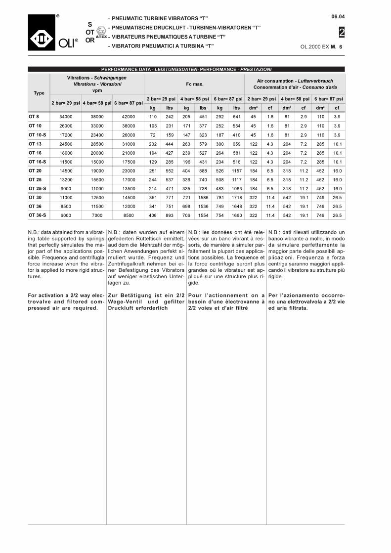

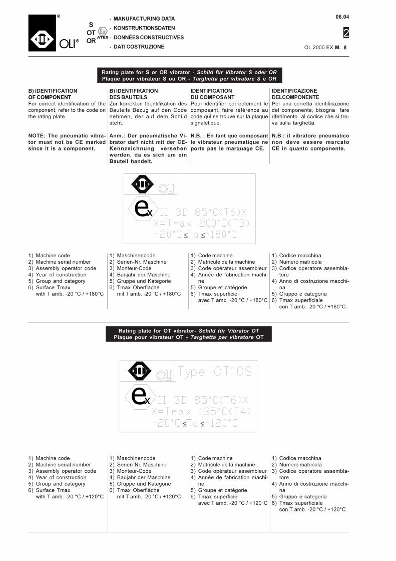


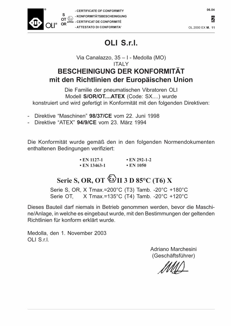


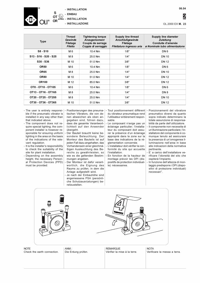


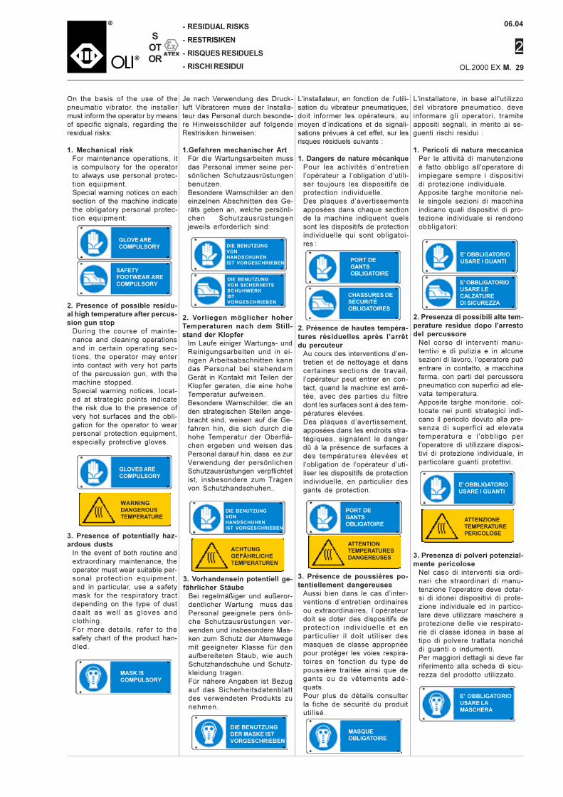


![· Web viewsyndrome*[ot] OR motor development disorder*[ot] OR Stereotypic Movement Disorder*[ot] OR Body Rocking[ot] OR Body-Focused Repetitive Behavio*[ot] OR Head Banging[ot]](https://static.documents.pub/doc/80x56/5b0593dc7f8b9ad1768b921d/viewsyndromeot-or-motor-development-disorderot-or-stereotypic-movement-disorderot.jpg)


