20
S range 5.0 – 29 kW GRUNDFOS WASTEWATER

S range 5.0 – 29 kW
GRUNDFOS WASTEWATER

Grundfos
Grundfos offers a complete range of highlydependable, powerful sewage pumps, designedfor unscreened raw sewage. With more thanforty years’ experience in providing specialisedpumps and pumping equipment for all kinds ofwastewater and sewage, we know better thananyone what our customers demand from a wastewater pump.
> 2
Powerful pumps for unscreened raw sewage
> High pump efficiency over timeAdvanced technology makes the Grundfos pumpsextremely efficient and highly dependable.Innovative features such as SmartTrim adjustmentof the impeller clearance ensure long-term highpump efficiency and low life-cycle costs.
> Less downtimeThe inherent non-clogging design of our SuperVorteximpeller pumps and the excellent solids handlingcapability of our channel-impeller pumps guaranteemaximum up-time and substantial reductions inservice costs caused by pump jamming or clogging.
> Life-long reliabilityThe Grundfos wastewater pumps are of a well-provendesign that ensures life-long reliability even underthe most difficult operation conditions.
At Grundfos we strive to maintain a close dialoguewith our customers in order to constantly improveour pump designs and performance. Only this wayare we able to build the long-lasting relationshipson which our business is founded.
> 3
Installation options
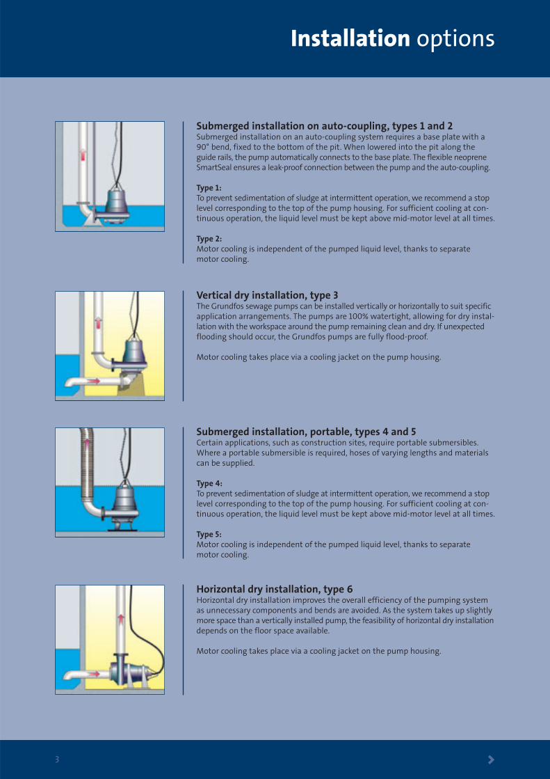
Submerged installation on auto-coupling, types 1 and 2Submerged installation on an auto-coupling system requires a base plate with a 90° bend, fixed to the bottom of the pit. When lowered into the pit along theguide rails, the pump automatically connects to the base plate. The flexible neopreneSmartSeal ensures a leak-proof connection between the pump and the auto-coupling.
Type 1:To prevent sedimentation of sludge at intermittent operation, we recommend a stoplevel corresponding to the top of the pump housing. For sufficient cooling at con-tinuous operation, the liquid level must be kept above mid-motor level at all times.
Type 2:Motor cooling is independent of the pumped liquid level, thanks to separate motor cooling.
Vertical dry installation, type 3The Grundfos sewage pumps can be installed vertically or horizontally to suit specificapplication arrangements. The pumps are 100% watertight, allowing for dry instal-lation with the workspace around the pump remaining clean and dry. If unexpectedflooding should occur, the Grundfos pumps are fully flood-proof.
Motor cooling takes place via a cooling jacket on the pump housing.
Submerged installation, portable, types 4 and 5Certain applications, such as construction sites, require portable submersibles.Where a portable submersible is required, hoses of varying lengths and materialscan be supplied.
Type 4:To prevent sedimentation of sludge at intermittent operation, we recommend a stoplevel corresponding to the top of the pump housing. For sufficient cooling at con-tinuous operation, the liquid level must be kept above mid-motor level at all times.
Type 5:Motor cooling is independent of the pumped liquid level, thanks to separate motor cooling.
Horizontal dry installation, type 6Horizontal dry installation improves the overall efficiency of the pumping systemas unnecessary components and bends are avoided. As the system takes up slightlymore space than a vertically installed pump, the feasibility of horizontal dry installationdepends on the floor space available.
Motor cooling takes place via a cooling jacket on the pump housing.

4
Tough and reliable pumps…
The Grundfos submersible sewage pumps are designed to reduce energyconsumption and to keep downtime costs at a minimum. Maintaining peakefficiency throughout the entire lifetime of the system is a key issue:
Heavy-duty maintenance-free greased-for-life ball bearings.
Watertight encapsulated motor,insulation class F (155°C), enclosureclass IP 68, with three thermalsensors in the stator windings.
Seal condition monitoring.The WIO, Water-in-Oil sensorplaced in the oil housinggives early warning of sealleakage (optional, fromrange 50).
The Grundfos SmartSealgasket system provides a completely leak-proof connection.
Double mechanical shaft seal system in intermediate oil chamberfor reliable sealing between thepumped liquid and the motor.Primary seal with SiC/SiC rings, and SiC/carbon rings in the secondary seal.
5 Details > 5
– with many unique features
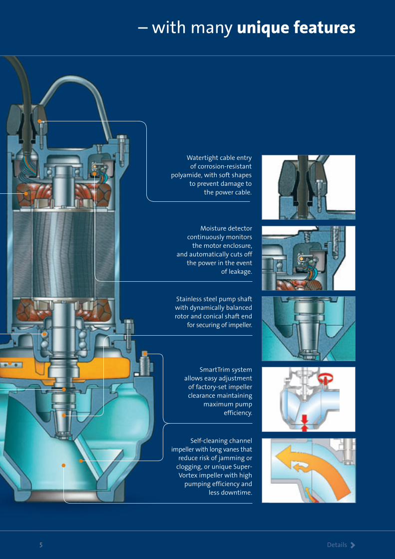
Watertight cable entry of corrosion-resistant
polyamide, with soft shapes to prevent damage to
the power cable.
SmartTrim systemallows easy adjustment
of factory-set impellerclearance maintaining
maximum pumpefficiency.
Self-cleaning channel impeller with long vanes that
reduce risk of jamming orclogging, or unique Super-Vortex impeller with high
pumping efficiency and less downtime.
Moisture detector continuously monitors
the motor enclosure,and automatically cuts off
the power in the eventof leakage.
Stainless steel pump shaftwith dynamically balancedrotor and conical shaft end
for securing of impeller.
Motor > 6
Operating conditions
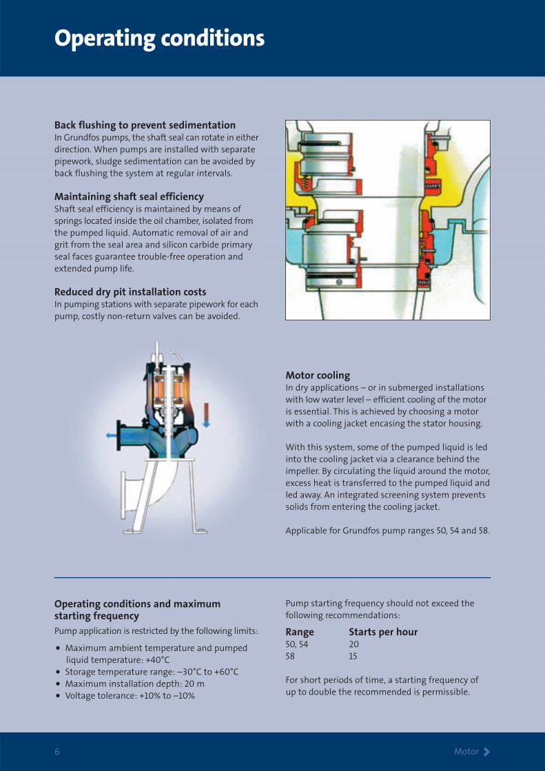
Back flushing to prevent sedimentationIn Grundfos pumps, the shaft seal can rotate in eitherdirection. When pumps are installed with separatepipework, sludge sedimentation can be avoided byback flushing the system at regular intervals.
Maintaining shaft seal efficiencyShaft seal efficiency is maintained by means ofsprings located inside the oil chamber, isolated fromthe pumped liquid. Automatic removal of air andgrit from the seal area and silicon carbide primaryseal faces guarantee trouble-free operation andextended pump life.
Reduced dry pit installation costsIn pumping stations with separate pipework for eachpump, costly non-return valves can be avoided.
Motor coolingIn dry applications – or in submerged installationswith low water level – efficient cooling of the motoris essential. This is achieved by choosing a motorwith a cooling jacket encasing the stator housing.
With this system, some of the pumped liquid is ledinto the cooling jacket via a clearance behind theimpeller. By circulating the liquid around the motor,excess heat is transferred to the pumped liquid andled away. An integrated screening system preventssolids from entering the cooling jacket.
Applicable for Grundfos pump ranges 50, 54 and 58.
Operating conditions and maximum starting frequencyPump application is restricted by the following limits:
• Maximum ambient temperature and pumpedliquid temperature: +40°C
• Storage temperature range: –30°C to +60°C
• Maximum installation depth: 20 m
• Voltage tolerance: +10% to –10%
Pump starting frequency should not exceed the following recommendations:
Range Starts per hour50, 54 2058 15
For short periods of time, a starting frequency ofup to double the recommended is permissible.

SuperVortex > 7
Grundfos SuperVortex impellers
A unique impeller designThe unique design of the Grundfos SuperVorteximpellers provides high pumping efficiency andless downtime. With a flow range from 4 l/s, theGrundfos SuperVortex-impeller pumps are theoptimum solution for all small pumping stations.
Full performance curve without operatinglimitations and vibrationsDue to the special power characteristics of theGrundfos SuperVortex-impeller pumps, it is possibleto run the pumps right up to the maximum flow on the curves without any risk of overloading themotor. The steep performance curve means minimal flow fluctuation with varying heads.
No clogging or jammingIn a SuperVortex-impeller pump, the flow is entirely outside the impeller. The design of theimpeller ensures that long fibres, rags, etc. passfreely through the pumps without getting caughtand without causing clogging or jamming. Thismeans less downtime and, consequently, reducedservice costs and higher pumping efficiency.
The design of the SuperVortex-impeller pumpsalso prevents the common problem of jammingbetween wear rings. A Grundfos SuperVortex-impeller pump needs no wear rings!
Conventional vortex impellerIn pumps fitted with a conventional vortex impeller,turbulent disturbance is liable to form around theimpeller. This will disrupt the flow pattern and resultin lower pumping efficiency and reduced head.
Grundfos SuperVortex impellerThe liquid passes freely outside the impellerwithout any turbulent disturbance.
Channel impellers > 8
Grundfos channel impellers
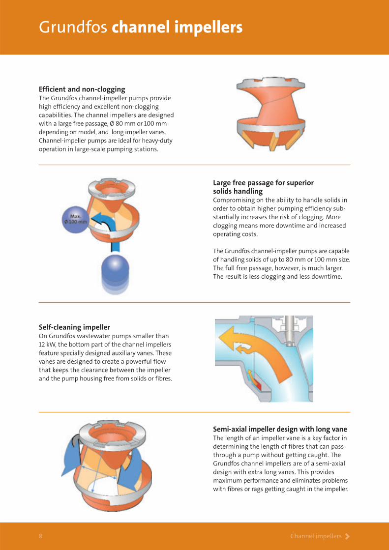
Efficient and non-cloggingThe Grundfos channel-impeller pumps providehigh efficiency and excellent non-clogging capabilities. The channel impellers are designedwith a large free passage, Ø 80 mm or 100 mmdepending on model, and long impeller vanes.Channel-impeller pumps are ideal for heavy-dutyoperation in large-scale pumping stations.
Large free passage for superior solids handlingCompromising on the ability to handle solids inorder to obtain higher pumping efficiency sub-stantially increases the risk of clogging. Moreclogging means more downtime and increasedoperating costs.
The Grundfos channel-impeller pumps are capableof handling solids of up to 80 mm or 100 mm size.The full free passage, however, is much larger.The result is less clogging and less downtime.
Semi-axial impeller design with long vaneThe length of an impeller vane is a key factor indetermining the length of fibres that can passthrough a pump without getting caught. TheGrundfos channel impellers are of a semi-axialdesign with extra long vanes. This providesmaximum performance and eliminates problemswith fibres or rags getting caught in the impeller.
Self-cleaning impeller On Grundfos wastewater pumps smaller than 12 kW, the bottom part of the channel impellersfeature specially designed auxiliary vanes. Thesevanes are designed to create a powerful flowthat keeps the clearance between the impellerand the pump housing free from solids or fibres.
Technical data > 9
Performance overview and type key
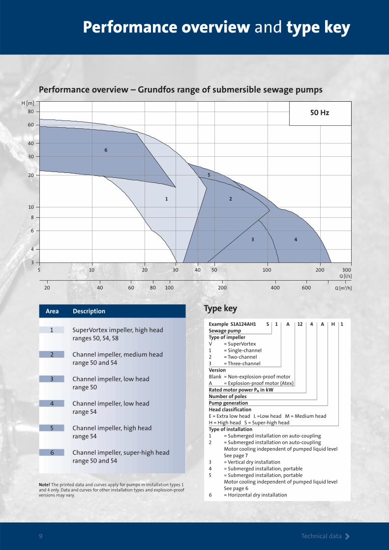
Performance overview – Grundfos range of submersible sewage pumps
Type key
5 10 20 30 40 50 100 200 300
3
4
6
8
10
20
30
40
60
80
20 40 60 80 100 200 400 600
1 2
3 4
5
6
H [m]
Q [l/s]
Q [m3/h]
50 Hz
Example S1A124AH1 S 1 A 12 4 A H 1Sewage pumpType of impellerV = SuperVortex1 = Single-channel2 = Two-channel3 = Three-channelVersionBlank = Non-explosion-proof motorA = Explosion-proof motor (Atex)Rated motor power PN in kWNumber of polesPump generationHead classificationE = Extra low head L =Low head M = Medium headH = High head S = Super-high headType of installation1 = Submerged installation on auto-coupling2 = Submerged installation on auto-coupling Motor cooling independent of pumped liquid level See page 73 = Vertical dry installation4 = Submerged installation, portable5 = Submerged installation, portable Motor cooling independent of pumped liquid level See page 66 = Horizontal dry installation
1 SuperVortex impeller, high head ranges 50, 54, 58
2 Channel impeller, medium head range 50 and 54
3 Channel impeller, low head range 50
4 Channel impeller, low head range 54
5 Channel impeller, high head range 54
6 Channel impeller, super-high head range 50 and 54
Area Description
Note! The printed data and curves apply for pumps in installation types 1and 4 only. Data and curves for other installation types and explosion-proofversions may vary.

Performance > 10
SuperVortex-impeller pumps
High head – ranges 50, 54, 58
Electrical and technical dataPump curve
No. Pump type IS/IN
Submerged installation Submerged installation, portable
Motor
1 SV 072 BH 50 Ø 80 Ø 100 163 100 80 180 Ø 100 160 7.4(9.4) 2952 16.9(20) 12.3(10.4) 2 SV 092 BH 50 Ø 80 Ø 100 163 100 80 180 Ø 100 160 9.4 2928 20 10,4 3 SV 122 BH 50 Ø 80 Ø 100 163 100 80 180 Ø 100 160 11.5(12) 2904 23.4(24.7) 8.9(7.6) 4 SV 152 H 54 Ø 80 Ø 80 248 - - - Ø 80 248 15 2780 30 9.1 5 SV 212 H 54 Ø 80 Ø 80 248 - - - Ø 80 248 21.0 2780 41.2 6.6 6 SV 302 H 58* Ø 80 Ø 150 410 - - - Ø 150 410 29 2916 59.0 6.9
() Motor data in brackets apply to installations 2, 3, 5 and 6. * Not available in Ex-version.
Dry installation
Pump range
Max. solidssize [mm]
Outlet[mm]
Weight[kg]
Weight[kg]
Hose[mm]
Weight[kg]
nN
[min-1]IN 400 V
[A]PN
[kW]InletDN
OutletDN
0 4 8 12 16 20 24 28 32 36 40 44 Q [l/s]
0
5
10
15
20
25
30
35
40
45
50
55
60
65
70
75
H[m]
0 20 40 60 80 100 120 140 Q [m3/h]
SV50 Hz
ISO 9906 Annex A
65321 4
Pump range, modular conceptGrundfos sewage pumps are of modular design. This means that pumps belonging to the same model rangeshare many common spare parts. This allows for interchangeability of impellers and hydraulics.
Pumping station with 3 vertical dry installed sewage pumps.
0 10 20 30 40 50 60 70 80 90 Q [l/s]
0
2
4
6
8
10
12
14
16
18
20
22
24
26
28
0 50 100 150 200 250 300 Q [m3/h]
S150 Hz
ISO 9906 Annex A
2 3 4
5 6 7
1
H[m]
Performance > 11
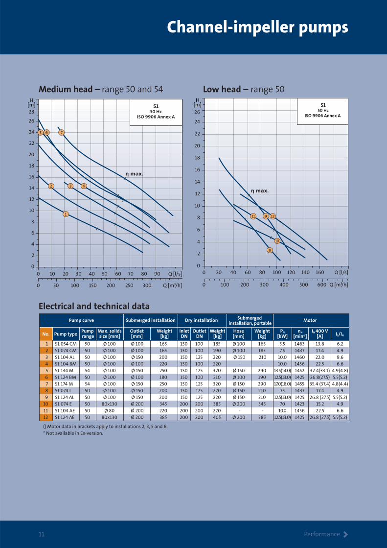
Channel-impeller pumps
0 20 40 60 80 100 120 140 160 Q [l/s]0
2
4
6
8
10
12
14
16
18
20
22
24
26
0 100 200 300 400 500 600 Q [m3/h]
S150 Hz
ISO 9906 Annex A
911 12
8
10
H[m]
Electrical and technical data
Pump curve
No. Pump type IS/IN
Submerged installation Submerged installation, portable
Motor
1 S1 054 CM 50 Ø 100 Ø 100 165 150 100 185 Ø 100 165 5.5 1463 13.8 6.2 2 S1 074 CM 50 Ø 100 Ø 100 165 150 100 190 Ø 100 185 7.5 1437 17.4 4.9 3 S1 104 AL 50 Ø 100 Ø 150 200 150 125 220 Ø 150 210 10.0 1460 22.0 9.6 4 S1 104 BM 50 Ø 100 Ø 100 220 150 100 220 - - 10.0 1456 22.5 6.6 5 S1 134 M 54 Ø 100 Ø 150 250 150 125 320 Ø 150 290 13.5(14.0) 1452 32.4(33.1) 4.9(4.8) 6 S1 124 BM 50 Ø 100 Ø 100 180 150 100 210 Ø 100 190 12.5(13.0) 1425 26.8(27.5) 5.5(5.2) 7 S1 174 M 54 Ø 100 Ø 150 250 150 125 320 Ø 150 290 17.0(18.0) 1455 35.4 (37.4) 4.8(4.4) 8 S1 074 L 50 Ø 100 Ø 150 200 150 125 220 Ø 150 210 7.5 1437 17.4 4.9 9 S1 124 AL 50 Ø 100 Ø 150 200 150 125 220 Ø 150 210 12.5(13.0) 1425 26.8 (27.5) 5.5(5.2) 10 S1 074 E 50 80x130 Ø 200 345 200 200 385 Ø 200 345 7.0 1423 15.2 4.9 11 S1 104 AE 50 Ø 80 Ø 200 220 200 200 220 - - 10.0 1456 22.5 6.6 12 S1 124 AE 50 80x130 Ø 200 385 200 200 405 Ø 200 385 12.5(13.0) 1425 26.8 (27.5) 5.5(5.2)
() Motor data in brackets apply to installations 2, 3, 5 and 6.* Not available in Ex-version.
Dry installation
Pump range
Max. solidssize [mm]
Outlet[mm]
Weight[kg]
Weight[kg]
Hose[mm]
Weight[kg]
nN
[min-1]IN 400 V
[A]PN
[kW]InletDN
OutletDN
Medium head – range 50 and 54 Low head – range 50

Performance > 12
Channel-impeller pumps
0 20 40 60 80 100 120 140 160 180 200 220 240 Q [l/s]0
2
4
6
8
10
12
14
16
18
20
22
24
26
0 100 200 300 400 500 600 700 800 Q [m3/h]
S1, S250 Hz
ISO 9906 Annex A
215
3 6
4
H[m]
0 10 20 30 40 50 60 70 80 Q [l/s]
0
4
8
12
16
20
24
28
32
36
40
0 50 100 150 200 250 300 Q [m3/h]
S150 Hz
ISO 9906 Annex A
1211109
7 8
H[m]
Electrical and technical dataPump curve
No. Pump type IS/IN
Submerged installation Submergedinstallation, portable
Motor
1 S1 134 BL 54 Ø 100 Ø 200 335 200 200 340 Ø 200 300 13.5(14.0) 1452 32.4(33.1) 4.9(4.8) 2 S1 174 BL 54 Ø 100 Ø 200 335 200 200 350 Ø 200 320 17.0(18.0) 1455 35.4(37.4) 4.8(4.4) 3 S2 134 L 54 Ø 100 Ø 200 335 200 200 350 Ø 200 300 13.5(14.0) 1452 32.4(33.1) 4.9(4.8) 4 S2 134 E 54 Ø 100 Ø 250 480 250 250 495 - - 13.5(14.0) 1452 32.4(33.1) 4.9(4.8) 5 S2 174 L 54 Ø 100 Ø 200 335 200 200 350 Ø 200 320 17.0(18.0) 1455 35.4(37.4) 4.8(4.4) 6 S2 174 E 54 Ø 100 Ø 250 480 250 250 495 - - 17.0(18.0) 1455 35.4(37.4) 4.8(4.4) 7 S1 054 H 50 Ø 80 Ø 100 205 100 100 215 Ø 100 205 5.5 1463 13.8 6.2 8 S1 074 H 50 Ø 80 Ø 100 205 100 100 215 Ø 100 205 7.5 1437 17.4 4.9 9 S1 104 AH 50 Ø 100 Ø 100 220 100 100 220 - - 10.0 1456 22.5 6.6 10 S1 124 AH 50 Ø 80 Ø 100 235 100 100 255 Ø 100 235 12.5(13.0) 1425 26.8(27.5) 5.5(5.2) 11 S1 134 H 54 Ø 80 Ø 100 285 150 100 295 Ø 100 290 13.5(14.0) 1452 32.4(33.1) 4.9(4.8) 12 S1 174 H 54 Ø 80 Ø 100 285 150 100 295 Ø 100 290 17.0(18.0) 1455 35.4(37.4) 4.8(4.4)
() Motor data in brackets apply to installations 2, 3, 5 and 6.* Not available in Ex-version.
Dry installation
Pump range
Max. solidssize [mm]
Outlet[mm]
Weight[kg]
Weight[kg]
Hose[mm]
Weight[kg]
nN
[min-1]IN 400 V
[A]PN
[kW]InletDN
OutletDN
Low head – range 54 High head – range 50 and 54

Super-high head – range 50 and 54
0 4 8 12 16 20 24 28 32 36 40 44 Q [l/s]
15
20
25
30
35
40
45
50
55
60
65
0 20 40 60 80 100 120 140
H[m]
Q [m3/h]
S150 Hz
ISO 9906 Annex A
1
32
Electrical and technical data
Pump curve
No. Pump type IS/IN
Submerged installation Motor
1 S1 074 S 50 Ø 80 Ø 100 205 100 100 215 7.5 1437 17.4 4.92 S1 212 H* 54 Ø 80 Ø 80 248 - - - 21.0 2780 41.2 6.63 S1 212 S* 54 Ø 80 Ø 80 242 - - - 21.0 2780 41.2 6.6
*Not available in Ex-version.
Dry installation
Pump range
Max. solidssize [mm]
Outlet[mm]
Weight[kg]
Weight[kg]
nN
[min-1]IN 400 V
[A]PN
[kW]InletDN
OutletDN
Material specifications
Stator housing Cast iron EN-JL1040 -Pump housing Cast iron EN-JL1040 -Impeller, S1 and S2 pumps Cast iron EN-JL1040 -Impeller, SV pumps Ductile iron EN-JS1050 80-55-06Pump shaft Stainless steel 1.4460 329Bolts and nuts Stainless steel 1.4436 316Cooling jacket, pump ranges 50-58 Ductile iron EN-JS1050 80-55-06O-rings NBR - -O-rings, mechanical shaft seal FKM - -Bearings Heavy-duty prelubricated ball bearings - -Primary shaft seal SiC/SiC - -Secondary shaft seal SiC/Carbon - -Lifting bracket, pump ranges 50–54 Ductile iron EN-JS1050 80-55-06Lifting bracket, pump ranges 58 Galvanized steel Rst 37-2Cable, 8 m EPDM - -Cable entry PA - -Surface protection 150 μ two-component epoxy coating - -Oil SAE 10 W 30 - -
Part Material DIN/EN AISI
Performance > 13

14
Dimensions and installation
Technical data >
DN A B C D E F G H K L M N O ØP ØR ØS ØT U V X Y ØZPump range/type
50 SV 072 BH 100 965 805 100 705 465 180 180 190 120 260 180 220 60 180 SV 092 BH 100 965 805 100 705 465 180 180 190 120 260 180 220 60 180 SV 122 BH 100 965 805 100 705 465 180 180 190 120 260 180 220 60 180 54SV 152 H 80 1055 945 110 610 370 180 180 215 180 260 325 375 75 160 SV 212 H 80 1055 945 110 610 370 180 180 215 180 260 325 375 75 160 58SV 302 H 150 1375 1155 220 870 575 225 225 225 250 380 280 500 100 240
220 18 20 205 180 121 180 48220 18 20 205 180 121 180 48220 18 20 205 180 121 180 48
200 18 24 230 203 80 80 60200 18 24 230 203 80 80 60
285 22 24 320 265 115 165 77
Dimensions [mm]
Submerged installation on auto-coupling
SuperVortex-impeller pumps
Channel-impeller pumps
DN A B C D E F G H K L M N O ØP ØR ØS ØT U V X Y ØZPump range/type
50S1 074 L 150 1050 845 205 730 455 210 240 190 250 380 280 500 100 240 S1 104 AL 150 1120 915 205 730 455 210 240 190 250 380 280 500 100 240 S1 124 AL 150 1120 915 205 730 455 210 240 190 250 380 280 500 100 240 S1 074 E 200 1070 930 140 950 550 325 365 260 300 400 540 600 150 295 S1 104 AE 200 1130 990 140 950 550 325 365 260 300 400 540 600 250 295 S1 124 AE 200 1130 990 140 950 550 325 365 260 300 400 540 600 250 295 S1 054 CM 100 975 875 100 610 375 180 190 190 120 260 180 220 60 180 S1 074 CM 100 975 875 100 610 375 180 190 190 120 260 180 220 60 180 S1 054 S 100 940 840 100 585 350 180 185 190 120 260 180 220 60 180 S1 074 H 100 940 840 100 585 350 180 185 190 120 260 180 220 60 180 S1 074 S 100 940 840 100 585 350 180 185 190 120 260 180 220 60 180 S1 104 BM 100 1035 935 100 610 375 180 190 190 120 260 180 220 60 180 S1 124 BM 100 1035 935 100 610 375 180 190 190 120 260 180 220 60 180 S1 104 AH 100 1000 890 100 585 350 180 185 190 120 260 180 220 60 180 S1 124 AH 100 1000 890 100 585 350 180 185 190 120 260 180 220 60 180 54S2 134 E 250 1205 1060 145 1290 840 370 420 310 350 400 620 700 150 350 S2 174 E 250 1205 1060 145 1290 840 370 420 310 350 400 620 700 150 350 S1 134 BL 200 1215 1020 195 930 590 265 315 235 300 400 540 600 150 295 S1 174 BL 200 1215 1020 195 930 590 265 315 235 300 400 540 600 150 295 S2 134 L 200 1215 1020 195 930 590 265 315 235 300 400 540 600 150 295 S2 174 L 200 1215 1020 195 930 590 265 315 235 300 400 540 600 150 295 S1 134 M 150 1180 995 185 715 432 215 235 210 250 380 280 500 100 240 S1 174 M 150 1180 995 185 715 432 215 235 210 250 380 280 500 100 240 S1 134 H 100 1050 960 90 670 390 215 230 210 200 260 325 375 75 180 S1 174 H 100 1050 960 90 670 390 215 230 210 200 260 325 375 75 180 S1 212 H 80 1085 980 105 610 370 180 180 215 180 260 325 375 75 160 S1 212 S 80 1085 980 105 610 370 180 180 215 180 260 325 375 75 160
285 22 24 320 265 115 165 77285 22 24 320 265 115 165 77285 22 24 320 265 115 165 77340 22 28 460 320 140 20 88340 22 28 460 320 140 20 88340 22 28 460 320 140 20 88220 18 20 205 180 121 180 48220 18 20 205 180 121 180 48220 18 20 205 180 121 180 48220 18 20 205 180 121 180 48220 18 20 205 180 121 180 48220 18 20 205 180 121 180 48220 18 20 205 180 121 180 48220 18 20 205 180 121 180 48220 18 20 205 180 121 180 48
395 23 28 500 370 205 270 88395 23 28 500 370 205 270 88340 22 28 460 320 140 20 88340 22 28 460 320 140 20 88340 22 28 460 320 140 20 88340 22 28 460 320 140 20 88285 22 24 320 265 115 165 77285 22 24 320 265 115 165 77220 18 24 230 223 80 80 60220 18 24 230 223 80 80 60200 18 24 230 203 80 80 60200 18 24 230 203 80 80 60
Dimensions [mm]

Technical data >15
Vertical dry installation
DN1 DN2 A B C D E F G H ØJ ØK ØL ØM ØN ØP
Pump range/type
50SV 072 BH 100 80 1265 620 425 580 400 370 270 30° M16 180 200 160 24SV 122 BH 100 80 1265 620 425 580 400 370 270 30° M16 180 200 160 24
1919
Dimensions [mm]
SuperVortex-impeller pumps
Channel-impeller pumps
DN1 DN2 A B C D E F G H ØJ ØK ØL ØM ØN ØPPump range/type
50S1 074 L 150 130 1505 815 600 590 380 435 300 30° M20 240 250 210 24S1 104 AL 150 130 1570 815 600 590 380 435 300 30° M20 240 250 210 24S1 124 AL 150 130 1570 815 600 590 380 435 300 30° M20 240 250 210 24S1 074 E 200 200 1640 970 700 785 460 625 350 30° M20 295 340 295 24S1 104 AE 200 200 1700 970 700 785 460 625 350 30° M20 295 340 295 24S1 124 AE 200 200 1700 970 700 785 460 625 350 30° M20 295 340 295 24S1 054 CM 150 100 1520 805 600 492 312 380 300 30° M20 240 225 180 24S1 074 CM 150 100 1520 805 600 492 312 380 300 30° M20 240 225 180 24S1 054 H 100 100 1305 625 425 465 285 375 270 30° M16 180 225 180 24S1 074 H 100 100 1305 625 425 465 285 375 270 30° M16 180 225 180 24S1 074 S 100 100 1305 625 425 465 285 375 270 30° M16 180 225 180 24S1 104 BM 150 100 1580 805 600 492 312 380 300 30° M20 240 225 180 24S1 124 BM 150 100 1580 805 600 492 312 380 300 30° M20 240 225 180 24S1 104 AH 100 100 1365 625 425 465 285 375 270 30° M16 180 225 180 24 54S2 134 E 250 250 1910 1105 825 1120 750 730 400 30° M20 350 406 350 28S2 174 E 250 250 1910 1105 825 1120 750 730 400 30° M20 350 406 350 28S1 134 BL 200 200 1730 920 700 765 500 550 350 30° M20 295 340 295 24S1 174 BL 200 200 1730 920 700 765 500 550 350 30° M20 295 340 295 24S2 134 L 200 200 1730 920 700 765 500 550 350 30° M20 295 340 295 24S2 174 L 200 200 1730 920 700 765 500 550 350 30° M20 295 340 295 24S1 134 M 150 125 1640 840 600 575 360 445 300 30° M20 240 250 210 24S1 174 M 150 125 1640 840 600 575 360 445 300 30° M20 240 250 210 24S1 134 H 150 100 1605 815 600 570 355 435 300 30° M20 240 220 180 24S1 174 H 150 100 1605 815 600 570 355 435 300 30° M20 240 220 180 24
1919192424241919191919191919
24242424242419191919
Dimensions [mm]
50S1 074 L 150 1000 350 870 240 190 430 590 310S1 104 AL 150 1065 350 870 240 190 430 590 310S1 124 AL 150 1065 350 870 240 190 430 590 310S1 074 E 200 1030 550 1210 365 275 640 815 380S1 104 AE 200 1090 550 1210 365 275 640 815 380S1 124 AE 200 1090 550 1210 365 275 640 815 380S1 054 CM 100 1020 350 640 190 190 380 450 285S1 074 CM 100 1020 350 640 190 190 380 450 285S1 054 H 100 950 350 615 185 190 375 435 290S1 074 H 100 950 350 615 185 190 375 435 290S1 104 BM 100 1080 350 640 190 190 380 450 305S1 124 BM 100 1080 350 640 190 190 380 450 305S1 104 AH 100 1020 350 615 185 190 375 435 290S1 124 AH 100 1020 350 615 185 190 375 435 29054S1 134 BL 200 1125 550 1200 315 235 590 750 315S1 174 BL 200 1125 550 1200 315 235 590 750 315S2 134 L 200 1125 550 1200 315 235 590 750 315S2 174 L 200 1125 550 1200 315 235 590 750 315S1 134 M 150 1105 550 915 235 210 550 585 305S1 174 M 150 1105 550 915 235 210 550 585 305S1 134 H 100 1070 550 775 230 210 550 550 280S1 174 H 100 1070 550 775 230 210 550 550 280
Ø A B C D E F G HPump range/type
Dimensions [mm]
SuperVortex-impeller pumps
Channel-impeller pumps
50SV 072 BH 100 930 350 555 180 180 370 460 290SV 092 BH 100 930 350 555 180 180 370 460 290SV 122 BH 100 930 350 555 180 180 370 460 29054SV 152 H 80 1080 350 635 180 215 395 430 280SV 212 H 80 1080 350 635 180 215 395 430 28058SV 302 H 150 1375 700 1060 225 225 550 630 380
Ø A B C D E F G HPump range/type
Dimensions [mm]
Submerged installation, portable
Technical data >16
Dimensions and installation
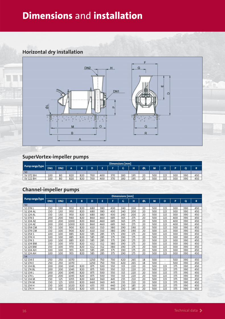
Horizontal dry installation
SuperVortex-impeller pumps
DN1 DN2 A B D E F G H ØL M O P Q RPump range/type
50SV 072 BH 100 80 820 820 700 400 370 180 195 20 500 115 300 390 450SV 122 BH 100 80 820 820 700 400 370 180 195 20 500 115 300 390 450
Dimensions [mm]
DN1 DN2 A B D E F G H ØL M O P Q RPump range/type
50S1 074 L 150 130 950 820 680 380 430 240 200 20 500 115 300 390 450S1 104 AL 150 130 950 820 680 380 430 240 200 20 500 115 300 390 450S1 124 AL 150 130 950 820 680 380 430 240 200 20 500 115 300 390 450S1 074 E 200 200 940 820 860 460 685 365 275 20 500 115 400 390 450S1 104 AE 200 200 1000 820 860 460 685 365 275 20 500 115 400 390 450S1 124 AE 200 200 1000 820 860 460 685 365 275 20 500 115 400 390 450S1 054 CM 150 100 900 820 610 310 380 190 190 20 500 115 300 390 450S1 074 CM 150 100 900 820 610 310 380 190 190 20 500 115 300 390 450S1 054 S 100 100 885 820 585 285 375 190 175 20 500 115 300 390 450S1 074 H 100 100 885 820 585 285 375 190 175 20 500 115 300 390 450S1 074 S 100 100 885 820 585 285 375 190 175 20 500 115 300 390 450 S1 104 BM 150 100 970 820 612 312 380 190 175 20 500 115 300 390 450S1 124 BM 150 100 970 820 612 312 380 190 175 20 500 115 300 390 450S1 104 AH 100 100 955 820 585 285 375 190 175 20 500 115 300 390 450S1 124 AH 100 100 955 820 585 285 375 190 175 20 500 115 300 390 45054S2 134 E 250 250 1070 - 1250 750 730 420 265 18 500 - 500 390 450 S2 174 E 250 250 1070 - 1250 750 730 420 265 18 500 - 500 390 450S1 134 BL 200 200 1045 820 875 500 550 315 220 20 500 115 375 390 450S1 174 BL 200 200 1045 820 875 500 550 315 220 20 500 115 375 390 450S2 134 L 200 200 1045 820 875 500 550 315 220 20 500 115 375 390 450S2 174 L 200 200 1045 820 875 500 550 315 220 20 500 115 375 390 450S1 134 M 150 125 1055 820 660 360 445 235 210 20 500 115 375 390 450S1 174 M 150 125 1055 820 660 360 445 235 210 20 500 115 375 390 450S1 134 H 150 100 1020 820 655 355 440 230 185 20 500 115 375 390 450S1 174 H 150 100 1020 820 655 355 440 230 185 20 500 115 375 390 450
Dimensions [mm]
Channel-impeller pumps

No. Picture
Description
Pumpoutlet[mm]
Pumprange
DN80
DN100
DN150
DN200
DN250
Productnumber
Lifting chainGalvanized lifting chain with lifting linkand safety hook, length 6 m.
Auto-couplingCast iron base plate incl. bend.
Auto-couplingSteel base plate excl. bend, incl. galvanized bolts and gaskets.
Cast iron bend, 90°PN 10.
Guide bar bracketUpper holder in stainless steel for twin guide rails.
Alarm status monitoringThe ASM 3 alarm status module is designed for moni-toring motor temperature and possible moisture leaks in submersible pump motors. The ASM 3 decodes the internal protection circuit P1-P2 of the pump in such a way that the thermal alarm and moisture alarm, which are normally connected in series, can be separated. The ASM 3 registers the status of the internal protection circuit of the pump. The pump must be prepared for ASM 3.
Non-return valveBall-type non-return valve with flanges.Cast-iron, epoxy coated.
80 ≥54 96066496
100 ≥54 96066472
150 ≥50 96066467
200 ≥50 96066482
250 ≥50 96066493
DN
80/80 96060928
80/100 96060929
100/100 96060930
100/150 96060931
150/150 96060934
150/200 96060935
200/200 96060938
200/300 96060940
250/250 96060942
250/300 96060943
250/350 96060944
80/100 50 • • 96067990
80/100 ≥54 • • 96067992
150 • 96457261
200 96067996
250 96067999
Max. load 1100 kg
Max. load 2000 kg
Max. load 3200 kg
Max. load 8000 kg
IO111
96060434
ASM 3 230 V
ASM 3 110 V
96069934
80 50 96066506100 50 96066511 100 ≥54 96066471
150 96066466
96468285
96468290
96468295
96468300
≥range 50
≥range 50
1
2
3
4
5
6
7
8
9
IO 111 moduleThe Grundfos IO111 module forms an interface between a Grundfos wastewater pump with analoque and digital sensors and the pump controller.
96575362
Analogue Water-in-Oil sensor
WIO Cable length 10 m 96294840
WIO Cable length 25 m 96295122
WIO Cable length 50 m 96294041
96002009
96002085
96003423
96003839
Base plate discharge flange PN10
80
100
150
200
••
• •••
••
••
••
Accessories > 17
Accessories

Accessories >18
Level switches and controllers
LC 107 controller, pneumatic versionwith level bells and tube for 1 pump3 x 400 V, direct-on-line starting.
LCD 107 controller, pneumatic versionwith level bells and tube for 2 pumps3 x 400 V, direct-on-line starting.
LC 108 controller for levelswitches for 1 pump 3 x 400 V,direct-on-line starting.
LC 108 controller for levelswitches for 1 pump 3 x 400 V,star-delta starting.
LCD 108 controller for levelswitches for 2 pumps 3 x 400 V,direct-on-line starting.
LCD 108 controller for levelswitches for 2 pumps 3 x 400 V,star-delta starting.
LC 110 controller for electrodes for 1 pump. 3 x 400 V, direct on-line starting
LCD 110 controller for electrodes for 2 pumps. 3 x 400 V, direct on-line starting
Description
Product numberOperating
currentper pump
[A]
Mainsswitch
required[A]
Includinghour counter
Standardcontroller
Includingstart counter
Includingcombined hour and
start counter
3.7 - 12.0 25 96 00 24 69 - - -
12.0 - 23.0 40 96 00 24 70 - - -
3.7 - 12.0 25 96 00 24 76 - - -
12.0 - 23.0 40 96 00 24 77 - - -
3.7 - 12.0 25 96 43 39 99 96 43 40 00 96 43 40 01 96 43 40 02
12.0 - 23.0 40 96 43 40 03 96 43 40 04 96 43 40 05 96 43 40 06
Level controllerNo.
3.7 - 12.0 25 96 48 40 87 - - -
12.0 - 23.0 40 96 48 40 88 - - -
3.7 - 12.0 25 96 48 40 95 - - -
12.0 - 23.0 40 96 48 40 96 - - -
6.4 - 20.0 25 96 43 79 28 - - -20.8 - 30.0 40 96 43 79 50 - - -20.8 - 59.0 80 96 43 79 70 - - -24.2 - 72.0 - 96 43 79 90 - - -
3.7 - 12.0 40 96 43 40 47 96 43 40 48 96 43 40 49 96 43 40 50
12.0 - 23.0 60 96 43 40 51 96 43 40 52 96 43 40 53 96 43 40 54
6.4 - 20.0 25 96 43 80 32 - - -20.8 - 30.0 40 96 43 80 52 - - -20.8 - 59.0 80 96 43 80 72 - - -24.2 - 72.0 - 96 43 80 92 - - -
No.
11
ProductnumberDescription
Battery back-up 96 00 25 20
Hour counter [400 V] 96 00 25 15
Start counter [400 V] 96 00 25 17
Combined hour and start counter [400 V] 96 00 25 19
25 [A] external mains switch for supply cable 96 00 25 11
40 [A] external mains switch for supply cable 96 00 25 12
80 [A] external mains switch for supply cable 96 00 25 13
LC-Ex4 96 44 03 00
Level switch with 10 m cable 96 00 33 32Level switch with 20 m cable 96 00 36 95Level switch for potentially explosive applications with 10 m cable 96 00 34 21Level switch for potentially explosive applications with 20 m cable 96 00 35 36Bracket for two level switches 96 00 33 38 1 pump without alarm (2 switches) 62 50 00 13Standard level switch 1 pump with alarm (3 switches) 62 50 00 14with 10 m cable and bracket 2 pumps without alarm (3 switches) 62 50 00 14 2 pumps with alarm (4 switches) 62 50 00 15 1 pump without alarm (2 switches) 62 50 00 16Level switches for potentially explosive areas 1 pump with alarm (3 switches) 62 50 00 17with 10 m cable and bracket 2 pumps without alarm (3 switches) 62 50 00 17 2 pumps with alarm (4 switches) 62 50 00 18
ProductnumberDescription
In addition to the chemical and thermal properties of the water-proof polypropylene housing as well as the polyurethane cable, the level switches are resistant to alcohol, uric acid, sewage, oils, fats, petrol, fruit acid, as well as a range of other chemicals.
Level switch
10
No.

The range >19
The Grundfos wastewater range
S range 15 – 155 kWBrochure covers the Grundfos range of
sewage pumps from 15 kW up to 155 kW for handling of raw sewage in
heavy-duty applications.Available in 50 Hz and 60 Hz versions.
S/SA ranges Up to 520 kWBrochure covers the Grundfos range of
super-heavy-duty channel pumps, axial flow pumps, and propeller
pumps from 7.5 kW up to 520 kW.
LC/LCD ranges – level controllersBrochure covers the Grundfos range ofcontrols for the wastewater pumpingsystems.
DW range 0.7 – 20 kWBrochure covers the Grundfos range of portable dewatering pumps (DW) from 0.8 kW to 20 kW for pumping raw waterwith abrasives.
S range pumps 1.65 – 5.0 kWThe brochure covers the Grundfos rangeof heavy-duty submersible SuperVortex
and channel-impeller pumps from 1.65 to 5.0 kW. All suitable for unscreened sewage.
SEN range 1.0 – 21 KwBrochure covers the Grundfos range of
heavy-duty stainless steel pumps (SEN)for aggressive and corrosive environments.
Multilift M, MD, MDV, and MD1 rangeBrochure covers Grundfos lifting stationsfor individual as well as multi-userapplications.
AMD, AMG, and AFG rangesBrochure covers the new range of mixers
and flowmakers for optimal control of liquids and solids throughout the
wastewater treatment process.
SRP range 3.0 – 24 kWBrochure covers the Grundfos range of
SRP submersible recirculation pumps for wastewater treatment
plants and flood control.Available in 50 Hz and 60 Hz versions.
SE1 and SEV ranges 1.1 – 11 kWThis brochure describes the innovative
SEV/SE1 pump lines. Fitted withSuperVortex or single-channel impellers,
these pumps can meet approximately80% of all wastewater pumping needs.
DP, EF, SE1 and SEV ranges 0.6 – 2.6 kWBrochure covers the Grundfos range ofsubmersible channel-impeller and Super-Vortex-impeller pumps from 0.6 to 2.6 kW.Designed for handling drainage, effluentand sewage from private dwellings.
Prefabricated pumping stationsBrochure covers the Grundfos range ofprefabricated pumping stations for collecting and removing drainwater, surface water, domestic and industrialwastewater and sewage.
SEG range 0.9 – 4.0 kW Brochure covers the Grundfos range ofsewage grinder pumps (SEG) for pumpingof wastewater with toilet discharge.

Being responsible is our foundationThinking ahead makes it possible
Innovation is the essence
www.grundfos.com 96
4875
14 0
206
VEN
TUR
EI/
S
Business with an attitude
Knowledge The sharing of knowledge, experience
and expertise across our global network will always
lead our business forward.
Innovation Combining the best technology with
fresh ways of thinking, we will continue to develop
even better pumps, systems, services and standards.
Solution With a complete product range, capable
of providing every conceivable water solution, we are
the most complete player on the market.


