S-Solo HWP District heating substation for direct heating and connection pipes for domestic hot water cylinder Instructions Table of contents Safety notes / Mounting & Start-up .................................2 Types / Main components / Dimensioned sketch ......4 Description ...............................................................................5 Heating circuit .........................................................................5 Domestic hot water ...............................................................7 Troubleshooting HE...............................................................8 Maintenance ............................................................................10 EU Declaration of conformity.............................................11
Transcript
S-Solo HWPDistrict heating substation for direct heating and connection pipes for domestic hot water cylinder
Instructions
Table of contents Safety notes / Mounting & Start-up .................................2
Types / Main components / Dimensioned sketch ......4
EU Declaration of conformity.............................................11
Safety notes
Storage
The following instructions refer to the standard design of the S-Solo HWP substation. Special versions are available on request.
To avoid injury of persons and damages to the device, it is absolutely necessary to read and observe these instructions carefully.
Necessary assembly, start-up and maintenance work must be performed by qualified and authorized personnel only.
Please comply with the instructions of the system manufacturer or system operator.
Unused connections and shut-off valves must be sealed with a plug. The plugs must be removed by an authorized service technician only.
Choice of materialsChoice of materials always in compliance with local legislation
Warning of high pressure and temperatureThe maximum temperature of the flow medium in the S-Solo HWP substations is 90 °C.
The maximum operating pressure of the substation is 10 bar.
Be aware of the installation’s permissible system pressure and temperature.
The risk of persons being injured and equipment damaged increases considerably if the recommended permissible operating parameters are exceeded.
The substation installation must be equipped with safety valves, however, always in accordance with local regulations.
Warning of hot surfaceThe substation has got hot surfaces, which can cause skin burns. Please be extremely cautious in close proximity to the substation.
Warning of electric shock riskBefore cleaning or servicing disconnect power supplies.
Warning of transport damageBefore substation installation, please make sure that the substation has not been damaged during transport.
Sound level≤ 55 dB
Corrosion protectionAll pipes and components are made of stainless steel and brass.
The maximum chloride compounds of the flow medium should not be higher than 300 mg/l.
The risk of equipment corrosion increases consi-derably if the recommended permissible chloride compounds are exceeded
If the substation is stored before installation, make sure that the place is dry and heated.
Disposal
This product consists of materials which must not be disposed of together with domestic waste. Dismantle the product and sort the components in various groups before disposal. Observe the disposal rules of the local legislation.
2 Produced by Danfoss Redan A/S · 03.2012
Instructions S-Solo HWP
Mounting The substation must be installed and connected by authorized service personnel only.
Installation must be in compliance with the local standards and regulations.
Allow for adequate space around the substation for mounting and maintenance purposes.
Prior to the substation installation all substation pipes and connections should be cleaned and rinsed.
The substation should be wall-mounted. The mounting sheet on the back of the substation has got holes for screw installation.
A symbol for each of the different connections is placed on the substation.
Tightening of connectionsDue to vibrations during transport all connections must be checked and tightened before the substation is installed.
After observing that the substations operates in accordance with the dimensioning basis, the connections must be tightened again and the substation can be taken into continuous use.
Heat meter assembly, fitting piece The flat station is equipped with a fitting piece for insertion of a heat meter.
Assembly of heat meter Loosen nuts from fitting piece, remove fitting piece and replace with heat meter. Mount the heat meter according to the medium flow direction. After mounting of heat meter remember to check all threaded connections
DCW meter (option) The substation can be equipped with a fitting piece for insertion of DCW meter.
Assembly of DCW meter Please refer to above assembly instructions for heat meter.
Start-up Prior to the S-Solo HWP installation all its pipes and connections should be cleaned and rinsed. After that the strainers should be cleaned.
Before starting-up, check if:- pipes are connected according to the circuit
diagram,- release valves are shut off,- threaded and flanged connections are
tightened.
All Danfoss substations have been pressure tested prior to delivery.
Electrical connection Electrical connections must be made by an au-thorised electrician only.Electrical connections must be made in accor-dance with current regulations and local stan-dards.
Before making electrical connections, please note the following:- Please read the relevant parts of safety notes.- The substation must be connected to 230 VAC and earth.- The substation must be connected via an exter- nal main switch, which can be disconnected by repairs.
3 Produced by Danfoss Redan A/S · 03.2013
Instructions S-Solo HWP
136
4 Produced by Danfoss Redan A/S · 03.2012
Instructions S-Solo HWP
Primäry Secundary
Components
1 Danfoss controller 2 Actuator HE 3 2-way valve * 4 Differential pressure controller 5 Danfoss sensor * 6 Manometer 7 Balancing valve 8 Air valve * 9 Circulation pump10 Thermometer, DH supply11 Thermometer, DH return12 Thermometer, cylinder return13 Thermometer, HE supply14 Thermometer, HE return15 Sensor pocket for heat meter *16 Fitting piece for heat meter17 Strainer18 Throttle valve* not visible on photo
Please note:Your substation may look different than the substation shown, as vari-ants with other components may be supplied. The control function, however, is basically as stated in this instruction manual.
Instructions for the fitted compo-nents will be supplied together with the substation.
District heating (DH) - In the following DH is specified as the heat source for the substations. However, also other heat sources such as an oil or gas boiler or solar heating etc. could be used as the primary supply for the fitted substations, enabling the Danfoss Redan substations to be used in numerous schemes with different energy sources, depending on the local operating conditions. In order to simplify we have decided to use DH as designation for the primary supply.
1 DH supply 5 HE supply2 DH return 6 HE return3 Cylinder return 4 Cylinder supply
Top view
wall
Cylinder connection
CylinderSupply
CylinderReturn
HEReturn
HESupply
DH Return
DHSupply
23
5
7
8
9
10 11 1217
14
1
17
18
4
1615
District heating substation for direct heating with mixing loop for single-family, semi-detached and terraced houses as well as flats. With one heating circuit and with connection pipes for cylinder on primary side. Designed for wall-mounting.
The heating temperature is controlled by an elec-tronic temperature controller Danfoss ECL with an outdoor temperature sensor. The substation is supplied with mixing ciruit and is thereby especially suitable for systems with floor heating. The task of the mixing circuit is to ensure a correct supply temperature for the heat-ing circuit (to protect the heating circuit against too high temperatures) and to ensure, that the return water is cooled down to the required temperature, before it flows back to the district heating plant. The mixing circuit temperature is controlled by an electronic temperature control-ler Danfoss ECL.
Description
General PLEASE NOTE, that other variants may be supplied. The control function, however, is basically as de-scribed below, and the control of the substation should be done in accordance with the enclosed pro-ducer instructions for the mounted controller.
2-way valve + electrical actua-tor.
The S-Solo HWP is supplied with a 2-way valve VS 2, which in combination with an electrical actua-tor Danfoss AMV 150 controls the heating circuit. The electrical actuator is preset from factory. In case of operating disturbances the actuator can be closed manually. Please see enclosed instructions,Electrical actuator AMV 1502-way valve VS 2
Close actuator by turning the manual override knob on top of actuator counterclockwise.
Manual override
Note: Press and hold the button on the bottom side of the actuator during manual override.
ČEsKY Servopohony s tříbodovým regulačním signálem AMV 150
www.danfoss.czStrana 6
POlsKI Siłowniki sterowane sygnałem 3-punktowym AMV 150
www.danfoss.plStrona 7
РУССКИЙ Электроприводы для трехпозиционного регулирования AMV 150
www.danfoss.ruСтраница 7
AMV 150 +
AMV 150 +
AMV 150 +
VS2 (DN 15)
VMV
AVQM (DN 15)
Heating circuitTemperature control
The temperature for the heating circuit is controlled electronically by the Danfoss ECL controller. The supply temperature ist calculated by the controller on basis of the outdoor temperature.The ECL Comfort 210 controller is loaded with a selected application by means of an ECL Application Key (Plug-&-Play). The Application Key contains information about application, languages and factory settings. From factory the VX Solo II H2WP is loaded with Applica-tion 1d. Other applications can, however, be loaded by means of the ECL Application Key, and it is possible to update the controller with new application software.
The controller is factory preset to turn off the heating automatically in the summer period.The controller settings can be changed in accord-ance with the enclosed producer instructions for the mounted controller.
See ECL Application Key Box with ECL Comfort 210/310 user guide and mounting guide, for further information. Please see enclosed user guide,
5 Produced by Danfoss Redan A/S · 03.2013
Instructions S-Solo HWP
6 Produced by Danfoss Redan A/S · 03.2012
Instructions S-Solo HWP
Circulation pump Grundfos Pumpe ALPHA2 L
Substation start-up /pump Do not start up the pump untill the system has been filled with the flow media and vented. See Grundfos instructions for the pump.
The pump is self-venting. It need not be vented before start-up.Air in the pump may cause noise, This noise ceases after a few minu-tes running.
Please note, that the system cannot be vented through the pumpPlease note, that the pump must not run dry.
PumpeneinstellungGRUNDFOS ALPHA2 L has seven optional settings which can beselected with the push-button.
Enclosed photo shows the recommended and al-ternative pump settings for system types.
The pump is set at the factory to the “Higest pro-portional-pressure curve” (PP2). In this control mode, the pump performance and consequently the power consumption are adjusted according to the heat demand in the system.If the recommended pump setting does not give the desired distribution of heat in the rooms of the house, change the pump setting to the shown al-ternative. For further infomation about pump settings please refer to the enclosed Grundfos instructions.
ALPHA2 L, Installation and operating instructions
AVPL is a self-acting differential pressure controller for PN 16 with adjustable differential pressure setting. Der AVPL keeps a constant differential pressure even with a variable system resistance. The AVPL can be set at any differential pressure be-tween 0,05 bar and 0,25 bar. The preset factory setting of the controller is 0,1 bar.To alter the differential pressure, use an Allen Key NV 3.1 full turn is equivalent to approx. 0.01 bar. The arrow on the controller top shows that the setting of the dif-ferential pressure is increased when it is turned clock-wise and reduced when turned counter-clockwise. The controller settings can be changed in accordance with the enclosed producer instructions.
Differential pressure controllerAVPL
Balancing valve For regulation of the flow through the system the S-Solo HWP can be supplied with a balancing valve.
For information about pre-regulation etc. please refer to the enclosed instructions for use: Kombi-3-PlusInstruction for use
Recommended and alternative pump settings according to system type.
7 Produced by Danfoss Redan A/S · 03.2013
Instructions S-Solo HWP
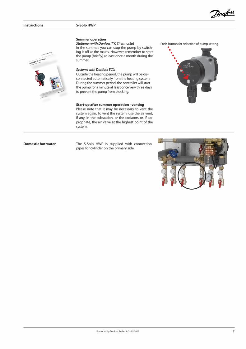
The S-Solo HWP is supplied with connection pipes for cylinder on the primary side.
Domestic hot water
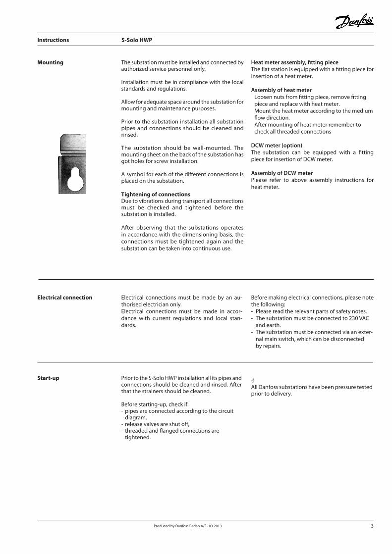
Summer operationStationen with Danfoss T°C ThermostatIn the summer, you can stop the pump by switch-ing it off at the mains. However, remember to start the pump (briefly) at least once a month during the summer.
Systems with Danfoss ECL:Outside the heating period, the pump will be dis-connected automatically from the heating system. During the summer period, the controller will start the pump for a minute at least once very three days to prevent the pump from blocking.
Start-up after summer operation - venting Please note that it may be necessary to vent the system again. To vent the system, use the air vent, if any, in the substation, or the radiators or, if ap-propriate, the air valve at the highest point of the system.
Push-button for selection of pump setting
GRUNDFOS ANLEITUNG
GRUNDFOS ALPHA2 L
Montage- und Betriebsanleitung
ALPHA2 LGRU
NDFOS INSTRUCTIONS
www.grundfos.
com/ALPHA2L
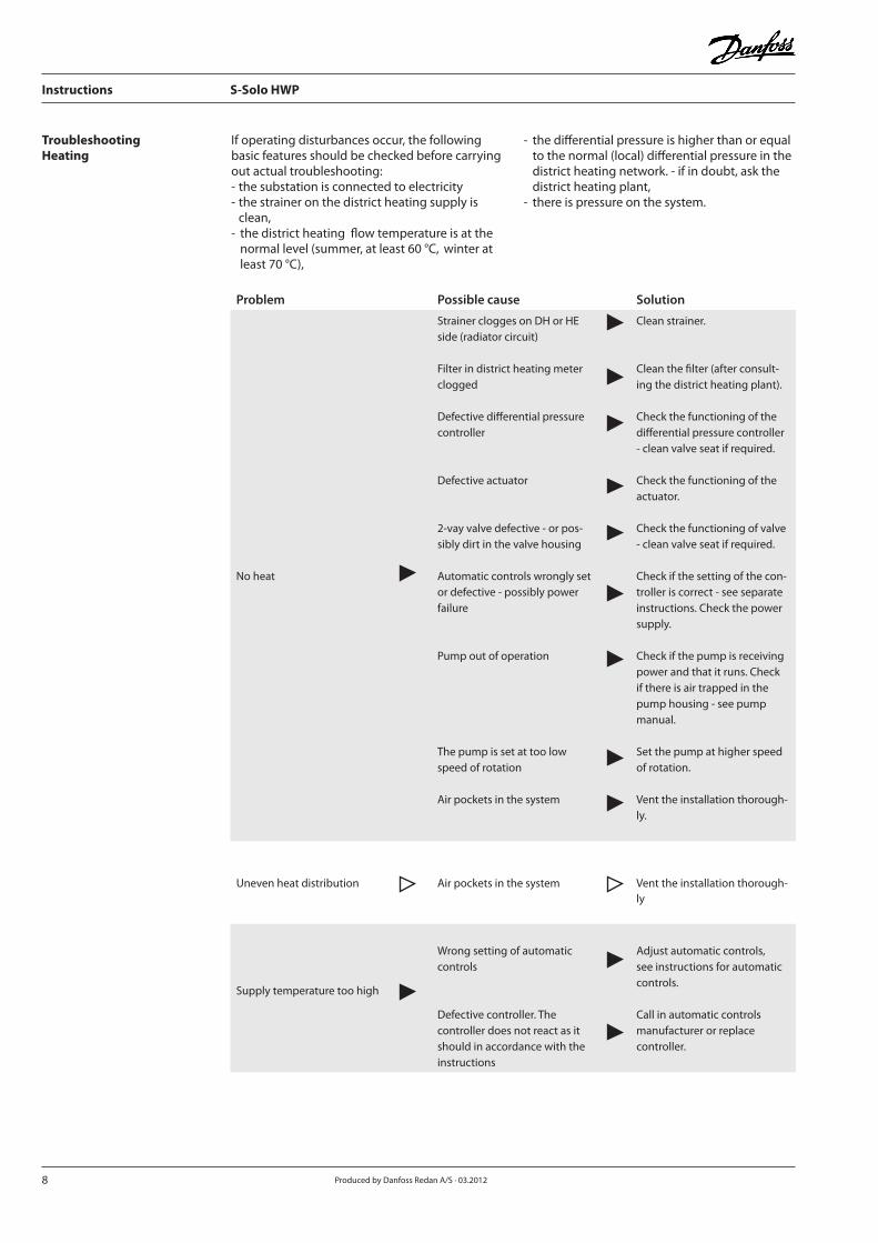
TroubleshootingHeating
Problem Possible cause Solution
No heat
Strainer clogges on DH or HE side (radiator circuit)
Filter in district heating meter clogged
Defective differential pressure controller
Defective actuator
2-vay valve defective - or pos-sibly dirt in the valve housing
Automatic controls wrongly set or defective - possibly power failure
Pump out of operation
The pump is set at too low speed of rotation
Air pockets in the system
Clean strainer.
Clean the filter (after consult-ing the district heating plant).
Check the functioning of the differential pressure controller - clean valve seat if required.
Check the functioning of the actuator.
Check the functioning of valve - clean valve seat if required.
Check if the setting of the con-troller is correct - see separate instructions. Check the power supply.
Check if the pump is receiving power and that it runs. Check if there is air trapped in the pump housing - see pump manual.
Set the pump at higher speed of rotation.
Vent the installation thorough-ly.
Uneven heat distribution Air pockets in the system Vent the installation thorough-ly
Supply temperature too high
Wrong setting of automatic controls
Defective controller. Thecontroller does not react as it should in accordance with the instructions
Adjust automatic controls, see instructions for automatic controls.
Call in automatic controls manufacturer or replace controller.
If operating disturbances occur, the following basic features should be checked before carrying out actual troubleshooting:- the substation is connected to electricity- the strainer on the district heating supply is clean,- the district heating flow temperature is at the normal level (summer, at least 60 °C, winter at least 70 °C),
- the differential pressure is higher than or equal to the normal (local) differential pressure in the district heating network. - if in doubt, ask the district heating plant,- there is pressure on the system.
8 Produced by Danfoss Redan A/S · 03.2012
Instructions S-Solo HWP
9 Produced by Danfoss Redan A/S · 03.2013
Instructions S-Solo HWP
Problem Possible cause Solution
Supply temperature too low
Wrong setting of automatic controls
Defective controller. The controller does not react as it should in accordance with the instructions
Wrong placement / fitting of outdoor temperature sensor
Strainer clogges.
Adjust automatic controls - see instructions for automatic controls
Call in automatic controls manufacturer or replace controller.
Place / fit outdoor temperature sensor correctly. Clean strainer.
Poor cooling
Too small heating surface/ too small radiators compared to the total heating requirement of the building.
Poor utilization of existing heat-ing surface.
The system is single-pipe
Increase total heating surface
Make sure that the heat is distributed evenly across the full heating surface - open all radiators and keep the radiator in the system from heating up at the bottom.
It is extremely important to keep the supply temperature to the radiators as low as ever possible, while maintaining a reasonable level of comfort.
TroubleshootingHeating
10 Produced by Danfoss Redan A/S · 03.2012
Instructions S-Solo HWP
The substation requires little monitoring, apart from routine checks and cleaning of strainers. To ensure the best operating conditions regular in-spection of the substation and a check of all re-levant operating parameters are recommended, for example in connection with meter reading.
Meter readingWe recommend that you read your meter regu-larly and that you write down the meter read.
Cooling / Return temperature readingThe cooling, i.e. the temperature difference be-tween district heating supply and district heating return is of great importance for the total heat economy. It is therefore very important to ob-serve the supply and return temperatures. CleaningAll strainers should be checked and cleaned at least once every year, typically in connection with start-up of the heating system.
Tightening of connectionsAll threaded and flanged connections should be checked and tightened in connection with meter reading. All threaded and flanged connections should be tightened regularly and especially in connection with start-up after the summer pe-riod.
Venting of systemAlways vent the radiators and the substation be-fore the heating season.
StrainerStrainers should frequently be cleaned from sediments by authorized personnel, according to producer’s instructions and dependent on the substation’s operating conditions.
Maintenance
Meter reading
Cooling
Cleaning
Tightening
Venting
Strainer
Danfoss Redan A/S District Energy
Omega 7, Søften DK-8382 Hinnerup
Telephone +45 87 43 89 43
EC-DECLARATION OF CONFORMITY
For CE marking in EU (European Union)
Danfoss Redan A/S District Energy DK-8382 Hinnerup
Declares under our sole responsibility that below products including all available power and control options:
S-Solo HWP
Main components: See Instruction Manual
Covered by this declaration is in conformity with the following directive(s), standard(s) or other norma-tive document(s), provided that the products are used in accordance with our instructions. EU Directives:
EMC Directive 2004/108/EEC EN 61000-6-1 2007 Electromagnetic compatibility- Generic standard: Immunity for residential, commercial and light industry.
EN 61000-6-2 2005 Electromagnetic compatibility- Generic standard: Immunity industry. EN 61000-6-3 2007 Electromagnetic compatibility- Generic standard: Emission for residential, commercial and light industry. EN 61000-6-4 2007 Electromagnetic compatibility- Generic standard: Emission industry.
Machinery Directive 2006/42/EEC EN ISO 14121-1 Safety of machinery -- Risk assessment
EN 60204-1-Safety of machinery - Electrical equipment of machines — Part 1: General requirements
PED Directive 97/23/EEC Conformity assessment procedure followed: Module A - Internal control of production All substations that falls under Article 3 §3 and category 1 shall not be CE-marked according to this directive
CE marked affixed year 2010 Approved by: Place and date of issue: Hinnerup, Aug. 24th, 2010 Name: Thavarupan Perinpam Title: Quality and Lean Manager


![HWP Bulletin Responding to Student Writing[1]](https://static.documents.pub/doc/80x56/55cf8ebe550346703b952804/hwp-bulletin-responding-to-student-writing1.jpg)


