24
SYNCHRONOUS MOTORS SYNCHRONOUS MOTORS www.DanaherMotion.com www.DanaherMotion.com

SYNCHRONOUS MOTORSSYNCHRONOUS MOTORSwww.DanaherMotion.comwww.DanaherMotion.com

2
ww
w.D
an
ah
er
Mo
tio
n.c
om
•
7
04
-5
88
-5
69
3
Danaher Mot ionand Super ior E lec t r i cSuperior Electric is a Danaher Motion brand, and is recognizedworldwide as the leading manufacturer of synchronous motors.Over 40 years ago, Superior Electric developed and patented theirsynchronous motors.
The Superior Electric family of automation products includes:• Step Motors• Step Motor Drives• Motion Controls• Synchronous Motors
This catalog highlights the latest selection of high torquesynchronous motors from Superior Electric. Our new line ofNEMA size 42 high torque motors complements and extends therange of our size 23 and 34 high torque motors. These motorsprovide world-class performance, and represent the best value ofany lineup ever offered by Superior Electric. They provide twice thetorque (and in some cases more than twice the torque) of olderconventional synchronous motors.
Your partner in Motion ControlDanaher Motion offers a comprehensive line of motors, drives,controls, and actuators designed to optimize the performance ofmotion control systems. These address a wide array ofrequirements, ranging from simple repetitive moves to complexmulti-axis motion. On-going product development enablesDanaher Motion to provide innovative, leading edge solutions toour customers.
One of the best reasons to select a Superior Electric product isDanaher Motion's superior service and support. Our products areavailable globally through the industry’s most extensive andexperienced distributor network. These trained distributors providevaluable technical assistance, in addition to fast delivery andservice. A team of application engineers backs our distributornetwork. The combined experience of this support system ensuresthat our customers receive prompt, quality attention to their needs,no matter where they are located.
Danaher Motion has extensive experience customizing motors tomeet specific design requirements. Our engineering staff will workwith you to achieve your product performance goals.
Further assistance and support is provided on the web atwww.DanaherMotion.com. Visitors to this site will find productinformation, technical specifications, and information on ourdistribution network.
Tab le of ContentsIntroduction to Synchronous Motors 3
Synchronous Motor Characteristics 4-5
KS06, KS09, KS11 Series – High Torque – NEMA 23, 34, 42 6-9
SS240, SS450 Series – NEMA Size 34 10-13
Hazardous Duty Motors – NEMA Sizes 42, 66 14-16
Phase Shifting Components 17
Gearbox Kits & Gearmotors 18-20
Application Assistance 21-22
Conversion Factors 23
SYNCHRONOUS MOTORS

3
ww
w.D
an
ah
er
Mo
tio
n.c
om
•
7
04
-5
88
-5
69
3
SYNCHRONOUS MOTORS
These motors offer substantial advantages in applications needing their very unique capabilities.
Superior Electric synchronous motors are high pole count motors that naturally turn at slower speeds (72 or 60 rpm). They only need a resistor – capacitor (RC) network to operate fromsingle-phase AC utility power. For loads that operate at 72 RPM orslower, they are very cost effective and simple to use.
Other motor technologies (induction, DC, servo and step motors)either need gear reducers, or electronic drives to match the speed ofSuperior Electric synchronous motors. The cost of just the gearreduction or the cost of the electronic drive will usually exceed thetotal cost of the Superior Electric synchronous motor.
For even slower speeds planetary gear reducers are offered. Superior Electric synchronous motors produce very low speeds with only modest gear reductions.
Performance Features• 72 rpm motor speed (with 60 Hz voltage)• 60 rpm motor speed (with 50 Hz voltage)• Constant speed does not vary with the load• 120 volt or 240 volt AC models• Torques: 70 to 1,500 oz-in (50-1,069 N-cm)• Gear reducers with ratios up to 125:1
and torques up to 5,000 oz-in (3,670 N-cm)• UL and CE hazardous duty versions• Fast starting, stopping, or reversing• Can be stalled indefinitely without overheating
High Torque Motor Construction
Typical Applications Due to their ease of use and inherent slow speeds, Superior Electric synchronous motors are used in a wide variety of applications including:• Stirring• Valve operation• Metering pumps• Cryogenic pumps• Simple position & process controls• Linear actuators• Edge guides• Variable transformers• Dampers• Conveyor systems• Table lifts• Remote control of switches, antennas, etc.
In t roduc t ionto Synchronous Motors
Robust Brushless Design
Reliable High Temperature Insulation
Special All Copper Windings
Leads Locked in Place
Rugged Square FrameConstruction
StainlessSteel Shaft
Long Life DoubleShielded Ball Bearings
Laminated Rotors withPermanent Magnets
Screw for GroundConnection

4
ww
w.D
an
ah
er
Mo
tio
n.c
om
•
7
04
-5
88
-5
69
3SYNCHRONOUS MOTORS
110
100
90
80
70
60
50
40
30
20
10
0
% O
F RA
TED
TORQ
UE
Input volts0 20 40 60 80 100 120 140
Typical Torque Versus Voltage for a Superior Motor
Synchronous Motor Charac ter i s t i c sStarting and StoppingRapid starting, stopping and reversing are among the advantages ofSuperior Electric synchronous motors. The motors will startwithin 1-1/2 cycles of the applied frequency and will stop within 5°.As shown in the typical starting curve, these motors will start andreach its full synchronous speed within 5 to 25 milliseconds.
Phase-Shifting NetworkThe KS series and hazardous duty motors use a two-phase windingdesign. They are usually operated from single-phase AC powerusing a phase shifting network consisting of one or two resistorsand a capacitor. These motors can also be operated directly from atwo-phase power source.
The SS240 – SS450 series use a three phase winding design. Theycan be driven directly from three-phase voltage or can be operatedfrom single-phase power using only a phase shifting capacitor.
Ratings and part numbers for the phase-shifting components areshown in the motor charts. Detailed phase shifting componentinformation is given on page 17. Be sure to select the correctcomponents for the frequency of the AC power source, since thecomponents needed for 50 hertz operation may be different fromthose required for operation at 60 hertz.
TemperatureAll Superior AC synchronous motors are rated for continuous dutyat a maximum ambient temperature of 40°C (104°F). Motor shelltemperature must not be allowed to exceed 100°C (212°F)measured with a thermocouple. The minimum ambienttemperature at which the motors may be operated is -40°C (-40°F).
Starting and Running CurrentIt is not necessary to consider high starting currents whendesigning a control system for a Superior Synchronous motor, sincestarting and operating current are, for all practical purposes,identical.
StallingIf a motor becomes stalled, it will not overheat and will continue todraw only rated current. However, if the motor is stalled byrunning up against a stop, it will vibrate against the stop.Operating the motor continuously in this manner may eventuallycause bearing failure.
Torque Versus VoltageAs indicated in the curve, the torque output of a Superior motor isapproximately proportional to the applied input voltage. Forintermittent operation, this characteristic can be used to provideincreased torque by increasing the voltage. For example, assumethat an application has a torque requirement of 200 ounce-inches(141 N-cm). Normally, a 240 ounce-inch (169 N-cm) Superiormotor would be adequate, but this application is subject to widevoltage fluctuations and, therefore, the 40 ounce-inch (28 N-cm)safety margin may be insufficient. The recommended practice is touse a motor having a higher torque rating. However, a largermotor may not fit in the available space. In this case, a step-uptransformer could be used to increase the voltage to the 240 ounce-inch motor by approximately 10%. Because operation at a highervoltage will cause a greater temperature rise, care must be taken toassure motor shell temperature does not exceed 100°C (212°F).
100
80
40
0
-40
0 10 20 30 40 50
AVG. SPEED 72 RPM
to 25 milliseconds.
Time From Start in Milliseconds
T i l S i Ch i i
Typical Starting Characteristicsfor a 72 rpm Motor

5
ww
w.D
an
ah
er
Mo
tio
n.c
om
•
7
04
-5
88
-5
69
3
SYNCHRONOUS MOTORS
Synchronous Motor Characteristics (Continued)
Speed Versus Frequency
The speed of a synchronous motor is directly proportional to theapplied frequency, as shown in the Speed vs. Frequency chart.However, because the winding impedance is also a function offrequency it is necessary to adjust the voltage, to provide a constantcurrent and torque at different excitation frequencies.
The voltage required at a specific frequency can be obtained fromthe Voltage vs. Frequency curve. When a two-phase motor isoperated from a two-phase source or a three-phase motor isoperated from a three-phase source, it is only necessary to changethe voltage and frequency to obtain the desired synchronous speed.When operating from a single-phase source it is necessary tochange the values of the phase shifting components at each newfrequency to provide the required phase shift.
Holding TorqueThe permanent magnet construction of a Superior motor provides asmall residual torque which helps hold the motor shaft in positionwhen the motor is de-energized. When additional holding torque isrequired, DC current can be applied to one winding when the acinput is removed. DC current can also be applied to both windingsif more holding torque is needed. The diagrams show typicalconnections for applying DC current to increase holding torque.Contact factory for voltage, current and holding torquespecifications.
200
150
100
50
0
400
300
200
100
00 20 40 60 80 100
24 48 72 96 120
VOL
TS P
ER P
HASE
(120
-VOL
T M
OTOR
S)
VOL
TS P
ER P
HASE
(240
-VOL
T M
OTOR
S)
Frequency (hertz)
Speed (rpm)
Typical Voltage Versus Frequency for a Superior Motor
Frequency(Hertz)
Speed72 rpm at 60 Hertz
Models10 1220 2430 3640 4850 6060 7270 8480 96
Typical Connections for Applying DCCurrent to Increase Holding Torque
RED
BLACK
WHITE
RELAY
CCW
CW
OFF
R
C
DCSUPPLY
ACLINE
1
2
3

123
KS06, KS09, KS11 Ser iesHigh Torque 60mm, 90mm, and 110mm Frame S izes (NEMA S izes 23, 34, 42)
6
ww
w.D
an
ah
er
Mo
tio
n.c
om
•
7
04
-5
88
-5
69
3SYNCHRONOUS MOTORS
KS 060911
LT
T1T2
WXY
06 NEMA 2309 NEMA 3411 NEMA 42
L LeadedT Terminal box
W 60 HzX 50 HzY 50/60 Hz
T1 120 VoltsT2 240 Volts
E Rear ShaftG��Gearbox + Ratio (KS09NEMA size 34 motors only)
# of StacksIE Motor Length
Phase Shifting Components
* Type NumberTorque (min) # Load Inertia
ampsWiring
DiagramResistor(s) Capacitator (240 VAC)
oz-in N-cm lb-in2 kg-cm2 Kit Number ohms watt Kit Number µF
^KS� 061T1Y 70 49 0.7 2.0 0.25 R/R/C 201052-034 600 12 201053-068 1.5
KS� 061T1Y 80 56 0.5 1.5 0.25 R/C 201052-033 1,000 12 201053-038 2
KS� 062T1Y 140 99 2.0 5.9 0.35 R/C 201052-035 600 25 201053-044 3
KS� 063T1Y 185 131 4.0 12 0.40 R/C 201052-049 400 50 201053-076 5
KS� 091T1Y 240 169 4 12 0.50 R/C 201052-037 300 50 201053-076 5
KS� 092T1Y 450 318 8 23 0.60 R/C 201052-041 250 50 201053-069 6
KS� 093T1Y 700 494 13 38 1.00 R/C 201052-027 150 100 201053-074 11
KS� 111T1W 700 494 7 20 1.20 R/C 201052-045 100 100 201053-032 12.5
KS� 112T1W 1,100 777 13 38 1.70 R/C 201052-101 75 100 201053-081 20
KS� 113T1W 1,500 1,059 15 44 2.10 R/C 201052-104 50 200 201053-081 20
120 Volt, 60 Hz, Single Phase, 72 RPM
KS11
KS09
KS06
^ Use this RRC phase shifting arrangement if very smooth operation is desired.
• Latest high torque construction• Motor torque up to 1500 oz-in (1059 N-cm)• 72 RPM @ 60 Hz - 60 RPM @ 50 Hz• 120 and 240 volt AC versions• Patented RRC network for smoother operation• Leaded or terminal box connections • Gearboxes available on KS09, NEMA 34 motors
See pages 18 & 19 for ratings

7
ww
w.D
an
ah
er
Mo
tio
n.c
om
•
7
04
-5
88
-5
69
3
SYNCHRONOUS MOTORS
Phase Shifting Components
* Type NumberTorque (min) # Load Inertia
ampsWiring
DiagramResistor(s) Capacitator (370 VAC)
oz-in N-cm lb-in2 kg-cm2 Kit Number ohms watt Kit Number µF
KS� 062T2Y 140 99 2.3 6.7 0.15 R/R/C 201052-036 1,100 25 201053-063 0.75
KS� 063T2Y 185 131 2.6 7.6 0.20 R/R/C 201052-050 1,000 25 201053-063 0.75
KS� 091T2Y 240 169 4 12 0.25 R/R/C 201052-039 900 50 201053-070 1
KS� 092T2Y 450 318 9 26 0.35 R/C 201052-045 1,000 100 201053-072 2
KS� 093T2Y 700 494 14 41 0.50 R/C 201052-047 600 100 201053-073 3
KS� 111T2W 700 494 9 26 0.60 R/C 201052-028 500 100 201053-030 3
KS� 112T2W 1,100 777 18 53 0.90 R/C 201052-102 200 100 201053-030 3
KS� 113T2W 1,500 1,059 17 50 1.30 R/C 201052-105 200 200 201053-029 6
Phase Shifting Components
* Type NumberTorque (min) # Load Inertia
ampsWiring
DiagramResistor(s) Capacitator (370 VAC)
oz-in N-cm lb-in2 kg-cm2 Kit Number ohm watt Kit Number µF
KS� 062T2Y 140 99 2.3 6.7 0.15 R/R/C 201052-036 1,100 25 201053-063 0.75
KS� 063T2Y 185 131 2.6 7.6 0.20 R/R/C 201052-050 1,000 25 201053-070 1
KS� 091T2Y 240 169 4.5 13 0.25 R/R/C 201052-039 900 50 201053-075 1.5
KS� 092T2Y 450 318 8 23 0.35 R/R/C 201052-043 600 50 201053-071 1.75
KS� 093T2Y 700 494 14 41 0.50 R/R/C 201052-046 400 100 201053-073 3
KS� 111T2X 700 494 5 15 0.60 R/C 201052-041 250 50 201053-030 3
KS� 112T2X 1,100 777 18 53 0.70 R/C 201052-103 250 100 201053-028 4
KS� 113T2X 1,500 1,059 27 79.0 1.40 R/C 201052-106 150 200 201053-082 7.5
240 Volt, 60 Hz, Single Phase, 72 RPM
KS11
KS09
KS06
240 Volt, 50 Hz, Single Phase, 60 RPM
KS11
KS09
KS06
# This is the maximum rigidly attached load inertia the motor will reliably start. If the load is attached to the motor with a coupling that has a 5º flex, the motors can start loads up to seven times listed.
KS06, KS09, KS11 Series (Continued)
R/C Connection
RED
CW
CCWC
R 1
2
ACINPUT
WHITE
BLACK
3
R/R/C Connection
REDGROUND SCREWGROUND SCREW
R
CW
CCWC
1
2
ACINPUT
WHITE
BLACK
3
R
NOTE:1 - Direction or rotation is determined when viewed from end opposite mounting surface.
2 - Number in diagrams represent terminal connection when motors are supplied with terminal boards.
Two-Phase OperationSingle-Phase Operation
Connection Diagrams

8
ww
w.D
an
ah
er
Mo
tio
n.c
om
•
7
04
-5
88
-5
69
3SYNCHRONOUS MOTORS
.688± .010[17.5±0.25]USABLE FLAT
.09 RAD MAX
.295 (4.95]Ø .2500 [6.350] .2495 [6.337]
.750±.04[19.1±1.1]
.21 [5.3]
MAX. LENGTHKSL061 SERIES 2.21 [56.1]KSL062 SERIES 3.06 [77.7]
KSL063 SERIES 4.06 [103.1]
.81±.02[20.3±.51]
Ø .2500 [6.350] .2495 [6.337] SEE NOTE
.002 [.051]- A -
Ø 1.500±.002 [38.10±0.06]
.003 [.077] A
DOUBLE ENDED SHAFT
#4-40 GND SCREWWHEN APPLICABLE
.003 [.077] A
.05 [1.3]
4X 1.48[37.6]
1.856 [47.14]
2.24 [56.9] MAX
Ø .3125 [7.938] .3120 [7.925]
63 SHAFT DETAIL12" [305] MIN LEAD LENGTH#22 AWG P0.35MM2]
NOTE: SEE SHAFT DETAIL FOR 63 SERIES
4 MTG HOLESØ.205 [5.21]
MAX. LENGTHKST061 SERIES 3.41 [86.6]
KST062 SERIES 4.26 [108.2] KST063 SERIES 5.26 [133.6]
REMOVABLE COVERFOR ACCESS TO#22 AWG [0.35mm 2]LEADS .50 - 14 NPT
KSL06 Leaded
KST06 Terminal Box
KSL11 Leaded
KST11 Terminal Box
MAX. LENGTHKSL111 SERIES 3.89 [98.81]KSL112 SERIES 5.91 [150.1]KSL113 SERIES 7.92 [201.2]
.06 [1.52]
.48 [12.19]
2.19 [55.63]
1.375 [34.93]
ø .7500 .7495[19.050][19.037]
ø 2.186 ± .002[ø 55.524 ± 0.051]
ø .5000 [12.700] .4995 [12.687]
4.325[109.85]
3.500[88.90] 4 MTG HOLES
ø.328 [8.33]
DOUBLE ENDED SHAFT
1.25 ± .06[31.75 ± 1.52]
12" [305] MINLEAD LENGTH#18 AWG [ 0.96 mm ]2
.1875
.1855[4.763][4.712]
.830
.813[21.08][20.65]
Dimensions are shown in inches (mm)
Dimensions are shown in inches (mm)
MAX. LENGTHKST111 SERIES 5.20 [132.1]KST112 SERIES 7.22 [183.4]KST113 SERIES 9.23 [234.4]

ww
w.D
an
ah
er
Mo
tio
n.c
om
•
7
04
-5
88
-5
69
3
9
SYNCHRONOUS MOTORS
KS09 Gearmotors
Shaft DimensionsMotorSeries
"B" Dia.in mm
"C" Flatin mm
KS� 091KS� 092
0.3750 9.525
0.3745 9.5120.328 8.33
KS� 0930.5000 12.700
0.4995 12.6870.450 11.43
KSL09 Leaded
KST09 Terminal Box
"B"
.0030 [.77] A
.19 [4.8]
.0030 [.77] A
MAX. LENGTHKSL091 SERIES 2.57 [65.1]KSL092 SERIES 3.77 [95.6]
KSL093 SERIES 4.97 [126.0]
.3750 [9.525]
.3745 [9.512]
DOUBLE ENDED SHAFT12" [305] MIN LEAD LENGTH#18 AWG [0.96mm 2]
1.19±.04[30.2±1.1]
4x 2.24 [56.9]
#6-32 GND SCREW
2.740 [69.60]
3.365 [69.60] 1.19±.02[30.2±0.60]
1.00[25.4]USABLEFLAT
R .09[2.29]
"C".002 [.051]
- A -
.063 [1.60]
Ø
Ø 2.875±.002 [73.03±0.06]
4 MTG. HOLESØ.223 [5.66]
MAX. LENGTHKST091 SERIES 3.90 [100]KST092 SERIES 5.10 [130]KST093 SERIES 6.30 [161]
REMOVABLE COVERFOR ACCESS TO#6 TERMINALS
.50 - 14 NPT
.125 [3.18]
.120 [3.2].001 [0.025] C
3.26[82.81]MAX
2X Ø 0.223 [5.66] THRU 180˚ APART ON A Ø3.88 [98.55]
.56 [14.22]
.57 [14.48]
Ø 3.39 [86.11]MAX.
1.10 [27.94] MINLENGTHØ (500)[12.7]1.79±0.03[45.47±0.77]
.500 [12.7]
.498 [12.64]- C -
.20[5.11]
MIN
#405 WOODRUFFKEY SUPPLIED
.25 MAX[6.35]
"B"MAX
"A"MAX
Ø 2.91[73.92]MAX
.41[10.49]
Dimensions are shown in inches (mm)
MotorSeries
GearboxRatio
Binch mm
Leaded Motors Terminal Box Motors
LeadedSeries
Ainch mm
TerminalMotors
Ainch mm
3:1 thru 5:19:1 thru 25:1
27:1 thru 125:13:1 thru 5:1
9:1 thru 25:127:1 thru 125:1
3:1 thru 5:19:1 thru 25:1
27:1 thru 125:1
1.19 30.21.81 46.02.38 60.51.19 30.21.81 46.02.38 60.51.19 30.21.81 46.02.38 60.5
KSL091
KSL092
KSL093
3.76 964.38 1114.95 1264.96 1265.58 1426.15 1566.16 1566.78 1727.35 187
KST091
KST092
KST093
5.09 1295.71 1456.28 1606.29 1606.91 1767.48 1907.49 1908.11 2068.68 220
KS� 091
KS� 092
KS� 093
See pages 18 & 19 or gearbox information

10
ww
w.D
an
ah
er
Mo
tio
n.c
om
•
7
04
-5
88
-5
69
3SYNCHRONOUS MOTORS
• Motor torque up to 450 oz-in (1059 N-cm)• 72 RPM @ 60 Hz - 60 RPM @ 50 Hz• 120 and 240 volt AC versions• Needs only a capacitor to operate from single-phase power• Available with integral capacitor for single phase operation• Operates directly from three-phase power• Leaded, connector or terminal box connections • Planetary gearboxes available – See pages 18 and 20
G��Gearbox + Ratio
SS 241242451452
Torque in oz-in, and Last #indicates Voltage
1 120 Volts2 240 Volts
SS241 = 240 oz-in, 120 VSS452 = 450 oz-in, 240 V
L Leads - Base offeringT Terminal Box(blank) Connector on LeadsC Covered CapacitorCT Capacitor in Terminal BoxE Rear Shaft
Phase ShiftingCapacitator (250 VAC)
* Type Number voltageTorque (min) # Load Inertia
ampsWiring
Diagramoz-in N-cm lb-in2 kg-cm2 Kit Number µF
SS241� 120 240 169 2.5 7 0.40 C 201053-037 7.5
SS451� 120 450 318 5.5 16 0.80 C 201053-042 14
120 Volt, 60 Hz, Single Phase, 72 RPM
Phase ShiftingCapacitator (250 VAC)
* Type Number voltageTorque (min) # Load Inertia
ampsWiring
Diagramoz-in N-cm lb-in2 kg-cm2 Kit Number µF
SS242� 208/240 240 169 2.5 7 0.20 C 201053-038 2
SS452� 208/240 450 318 7.5 22 0.30 C 201053-044 3
240 Volt, 60 Hz, Single Phase, 72 RPM
Phase ShiftingCapacitator (250 VAC)
* Type Number voltageTorque (min) # Load Inertia
ampsWiring
Diagramoz-in N-cm lb-in2 kg-cm2 Kit Number µF
SS242� 240 240 169 1 3 0.20 C 201053-038 2
SS242� 220 240 169 1 3 0.20 C 201053-041 2.5
SS452� 220/240 450 318 2 6 0.30 C 201053-061 4
240 Volt, 50 Hz, Single Phase, 60 RPM
SS240,SS450 Ser ies90mm Frame S ize (NEMA S izes 23, 34, 42)

11
ww
w.D
an
ah
er
Mo
tio
n.c
om
•
7
04
-5
88
-5
69
3
SYNCHRONOUS MOTORS
SS240, SS450 (Continued)
* Type Number voltageTorque (min) # Load Inertia
ampsWiring
Diagramoz-in N-cm lb-in2 kg-cm2
SS242� 208/240 250 177 2.5 7 0.20 3 Ø
SS452� 208 475 335 4.5 13 0.30 3 Ø
Three Phase, 208 - 240 Volt, 60 Hz, 72 RPM
* Type Number voltageTorque (min) # Load Inertia
ampsWiring
Diagramoz-in N-cm lb-in2 kg-cm2
SS242� 208 250 177 4 12 0.20 3 Ø
SS452� 208 475 335 4.5 13 0.30 3 Ø
Three Phase, 208 Volt, 50 Hz, 60 RPM
C Connection
RED
CW
CCW
MOTORFOR SINGLE
PHASEOPERATION
OFF
WHITE
BLACKINPUT LINE
SINGLEPHASE
DIRECTION OF ROTATIONDETERMINED WHEN VIEWEDFROM NAMEPLATE END OF MOTOR.
Single-Phase Operation
Connection DiagramsLead Color Connector
MotorTerminal
Box MotorRed Pin # 7 Terminal # 1
Black Pin # 6 Terminal # 3White Pin # 2 Terminal # 2
3 Ø Connection
WHITE
BLACK
CCW
CW
RED
PHASE A(RED)
PHASE B(BLACK)
PHASE C(WHITE*)
INPUTLINE
3-PHASE
DIRECTION OF ROTATIONDETERMINED WHEN VIEWEDFROM NAMEPLATE END OF MOTOR.
* WHITE IS NOT "NEUTRAL".
Three-Phase Operation
Mating connectors with 36” (914mm) long leadsare available for making connections to motorsthat have connectors. 36"
(914 mm)
CONNECTOR AMP #641437-9TERMINAL AMP #643067-9
Mating Connector with LeadsPart number 225505-001
Terminations

12
ww
w.D
an
ah
er
Mo
tio
n.c
om
•
7
04
-5
88
-5
69
3SYNCHRONOUS MOTORS
Leaded Motor
Terminal Box
SS240, SS450 (Continued)
Motor Type Ainch mm
SS241L SS241LE2.72 69
SS242L SS242LESS451L SS451LE
4.32 110SS452L SS452LE
Motor Type
SS241 SS241ESS242 SS242ESS451 SS451ESS452 SS452E
Motor Type Ainch mm
SS241T4.05 103
SS242TSS451T
5.65 144SS452T
Connector
Dimensions are shown in inches (mm)

13
ww
w.D
an
ah
er
Mo
tio
n.c
om
•
7
04
-5
88
-5
69
3
SYNCHRONOUS MOTORS
Covered Capacitor
Capacitor in Terminal Box
GearmotorsSee pages 18 and 20for gearbox information
MotorSeries
Gearbox RatioB
inch mm
Leaded & Connector Motors Terminaol Box Motors Covered Capacitor Motors Capacitor in Terminal Box Motors
Leaded MotorsConnector
MotorsA
inch mmMotor Type
Ainch mm
Motor TypeA
inch mmMotor Type
Binch mm
SS240
3:1 thru 5:1 1.19 30.2S241LG��
SS242LG��
SS241G��
SS242G��
3.91 99SS241TG��
SS242TG��
5.24 133SS241CG��
SS242CG��
5.88 149SS241CTG��
SS242CTG��
6.67 169
9:1 thru 25:1 1.81 46.0 4.53 115 5.86 149 6.50 165 7.29 185
27:1 thru 125:1 2.38 60.5 5.10 130 6.43 163 7.07 180 7.86 200
SS450
3:1 thru 5:1 1.19 30.2SS451LG��
SS452LG��
SS451G��
SS452G��
5.51 140SS451TG��
SS452TG��
6.84 174SS451CG��
SS452CG��
7.48 190SS451CTG��
SS452CTG��
8.27 210
9:1 thru 25:1 1.81 46.0 6.13 156 7.46 189 8.10 206 8.89 226
27:1 thru 125:1 2.38 60.5 6.70 170 8.03 204 8.67 220 9.46 240
Motor Type Ainch mm
SS241C4.69 119
SS242CSS451C
6.29 160SS452C
Motor Type Ainch mm
SS241CT5.48 139
SS242CTSS451CT
7.08 180SS452CT
Dimensions are shown in inches (mm)

14
ww
w.D
an
ah
er
Mo
tio
n.c
om
•
7
04
-5
88
-5
69
3SYNCHRONOUS MOTORS
Torque in oz-in, and Last # indicates voltage0 120 volts2 240 voltsX250=250 oz-in, 120 VX1102=1100 oz-in, 240 V
XXCE
X Meets UL Standards (conduit connection)
XCE Meets CE Standards(includes 10' (3m) cable)
• Motor torque up to 1500 oz-in (1059 N-cm)• 72 RPM @ 60 Hz - 60 RPM @ 50 Hz• 120 and 240 volt AC versions• UL Listed and CE certified versions• UL Listed versions - Class 1 Group D requirements• UL Listed versions have conduit connection• CE certified versions – EEx d IIC T5• CE certified versions have integral 10 ft (3 M) cable
Hazardous Duty Motors(NEMA S ize 42 & 66)
Motors having an “X” prefix (X250, etc.) are designed to meet ULStandard 674 for motors operating in Class 1 Group D hazardouslocations.
Class 1 is defined as locations in which gases or vapors are, or maybe, present in the air in quantities sufficient to produce explosionsor ignitable mixtures. Group D includes atmospheres containinggasoline, petroleum, naphtha, alcohol, acetone, lacquer solventvapors or natural gas.
Motors having a “XCE” prefix are designed to meet requirementsin hazardous locations as defined by CE directive 94/9/EC. Theyhave a flameproof enclosure, for use in surface industries exposedto gasses including hydrogen and acetylene. The maximumsurface temperature is 100°C.
UL Certified Motors (Prefix "X") CE Certified Motors (Prefix "XCE")

Phase Shifting
* Type Number Torque (min) # Load Inertiaamps
WiringDiagram
Resistor Capacitor (660VAC)
UL CE oz-in N-cm lb-in2 kg-cm Kit Number ohms watts Kit Number µFX252 XCE252 250 177 3 8.8 0.4 RC 201052-015 500 50 201053-012 1.75----- XCE702 700 494 10 30 0.6 RC 201052-028 500 100 201053-028 4
X1102 XCE1102 1,100 777 9 26 1.5 RC 201052-026 400 160 201053-029 6X1502 XCE1502 1,500 1,059 12 35 1.5 RC 201052-018 250 200 201053-019 9
Phase Shifting
* Type Number Torque (min) # Load Inertiaamps
WiringDiagram
Resistor Capacitor (330VAC)
UL CE oz-in N-cm lb-in2 kg-cm Kit Number ohms watts Kit Number µFX250 XCE250 250 177 3 8.8 0.6 RC 201052-013 150 50 201053-010 6.5X700 XCE700 700 494 10 30 1.1 RC 201052-027 150 100 201053-032 12.5
X1100 XCE1100 1,100 777 9 26 3 RC 201052-025 100 160 201053-026 17.5X1500 XCE1500 1,500 1,059 12 35 3 RC 201052-020 55 375 201053-014 30
15
ww
w.D
an
ah
er
Mo
tio
n.c
om
•
7
04
-5
88
-5
69
3
SYNCHRONOUS MOTORS
Hazardous Duty Motors (Continued)
120 Volt, 60 Hz, Single Phase, 72 RPM
# This is the maximum rigidly attached load inertia the motor will reliably start. If the load is attached to the motor with a coupling that has a 5º flex, the motor can start loads up to seven times listed.
Phase Shifting
* Type Number Torque (min) # Load Inertiaamps
WiringDiagram
Resistor Capacitor (660VAC)
UL CE oz-in N-cm lb-in2 kg-cm Kit Number ohms watts Kit Number µFX252 XCE252 250 177 3 8.8 0.4 RC 201052-015 500 50 201053-012 1.75----- XCE702 700 494 10 30 0.6 RC 201052-028 500 100 201053-030 3
X1102 XCE1102 1,100 777 9 26 1.5 RC 201052-026 400 160 201053-028 4X1502 XCE1502 1,500 1,059 12 35 1.5 RC 201052-018 250 200 201053-016 8
240 Volt, 60 Hz, Single Phase, 72 RPM
240 Volt, 50 Hz, Single Phase, 60 RPM
R/C Connection
RED
CW
CCWC
R 1
2
ACINPUT
WHITE
BLACK
3
GROUND SCREW
NOTE:1 - Direction or rotation is determined when viewed from end opposite mounting surface.
Single-Phase Operation
Connection Diagram

16
ww
w.D
an
ah
er
Mo
tio
n.c
om
•
7
04
-5
88
-5
69
3SYNCHRONOUS MOTORS
X250, X252, X700, X2CE250, XCE252, XCE700, XCE702
X1100, X1102, X1500, X1502, XCE1100, XCE1102, XCE1500, XCE1502
Hazardous Duty Motor Dimensions
Dimensions are shown in inches (mm)
Dimensions are shown in inches (mm)
Motor SeriesA Max.
inch mmB Max.
inch mmC Max.
inch mmX250 X252 5.06 129 1.17 29.7 4.20 107XCE250 XCE252 5.70 145 1.17 29.7 4.50 114
X700 7.45 189 1.38 35.1 4.20 107XCE700 XCE702 8.06 205 1.38 35.1 4.50 114
Motor SeriesA Max.
inch mmX1100 X1102 7.10 180XCE1100 XCE1102 7.60 193
X1500 X1502 8.41 2.14XCE1500 XCE1502 8.91 226

17
ww
w.D
an
ah
er
Mo
tio
n.c
om
•
7
04
-5
88
-5
69
3
Phase Sh i f t ing Components
SYNCHRONOUS MOTORS
PHASE SHIFTING COMPONENT DIMENSIONS
.50 [ 12.7 ] min. clearancerequired above terminals.
.18 [ 4.6 ] dia. hole
FIGURE C1
“D”
“A” “C”
“B”
“B”
“D”
FIGURE C2
A
B
C
Capacitor Kits
Resistor Kits
Kit Number Figure µfd VACA B C D
in mm in mm in mm in mm201053-010 C1201053-012 C1201053-014 C1201053-016 C1201053-019 C1201053-026 C1201053-028 C1201053-029 C1201053-030 C1201053-032 C1201053-037 C2201053-038 C2201053-041 C2201053-042 C2201053-044 C2201053-061 C2201053-063 C1201053-068 C2201053-069 C2201053-070 C1201053-071 C1201053-072 C1201053-073 C1201053-074 C2201053-075 C1201053-076 C2201053-081 C1201053-082 C1
* Kit contains two resistors. Dimensions shown are for one resistor.
6.51.753089
17.5463
12.57.52
2.51434
0.751.561
1.7523
111.55
207.5
330660330660660330660660660330250250250250250250370250250370370370370250370250330660
2.662.663.413.414.163.412.662.662.662.66
- - - - - -
2.66- -
2.662.662.662.66
- 2.66
- 3.413.41
67.667.686.686.6
105.786.667.667.667.667.6
- - - - - -
67.6- -
67.667.667.667.6
- 67.6
- 86.686.6
4.143.777.565.815.814.843.7
4.834.086.082.02.02.02.52.02.0
2.792.02.0
2.792.792.792.792.0
2.792.0
6.095.81
10596
19214814812394
12310415451515164515171515171717171517151
155148
1.311.311.911.911.971.911.311.311.311.31
- - - - - -
1.31- -
1.311.311.311.31
- 1.31
- 1.911.91
33334949504933333333- - - - - -
33- -
33333333-
33-
4949
2.162.162.912.913.662.912.162.162.162.161.100.660.671.150.680.812.160.661.102.162.162.162.161.302.161.102.912.91
55557474937455555555281717291721551728555555553355287474
Kit Number ohms wattsA B C
in mm in mm in mm4.884.8811.511.59.389.385.885.882.52.533
4.884.884.884.885.885.885.884.88
35.885.885.8811.511.511.5
12412429229223823815015064647676
12412412412415015015012476
150150150292292292
201052-013201052-015201052-018201052-020201052-025201052-026201052-027201052-028201052-033
* 201052-034201052-035
* 201052-036201052-037
* 201052-039201052-041
* 201052-043201052-045
* 201052-046201052-047201052-049
* 201052-050201052-101201052-102201052-103201052-104201052-105201052-106
15050025055
100400150500
1,000600600
1,100300900250600
1,000400600400
1,00075
20025050
200150
5050
2003751601601001001212252550505050
1001001005025
100100100200200200
1.441.442.752.692.52.5
2.762.760.940.941.941.941.441.441.441.442.762.762.761.441.942.762.762.762.752.752.75
373770
68.36464707024245050373737377070703750707070707070
11
1.131.251.131.131.381.380.320.320.750.75
1111
1.381.381.38
10.751.381.381.381.131.131.13
25.425.428.731.828.728.735358.18.11919
25.425.425.425.4353535
25.419353535
28.728.728.7

18
ww
w.D
an
ah
er
Mo
tio
n.c
om
•
7
04
-5
88
-5
69
3SYNCHRONOUS MOTORS
Gearbox K i t s & Gearmotors
Gearbox (G) Ratio Kit PartNumber
"B" Body length Typical Input Shaft Lost Motion
Typical Output Shaft Backlash
Reflected Momen of Inertia Efficiency
In mm Degrees Degrees Lb-In2 Kg-Cm2 3:1 220763-003 1.19 30.2 6 2 0.105 0.307 88%4:1 220763-004 1.19 30.2 7 2 0.035 0.102 88%5:1 220763-005 1.19 30.2 8 2 0.021 0.061 88%9:1 220763-009 1.81 46.0 43 2 0.115 0.336 77%
12:1 220763-012 1.81 46.0 61 2 0.041 0.120 77%15:1 220763-015 1.81 46.0 81 2 0.024 0.070 77%16:1 220763-016 1.81 46.0 58 2 0.037 0.108 77%20:1 220763-020 1.81 46.0 65 2 0.023 0.067 77%25:1 220763-025 1.81 46.0 73 2 0.022 0.064 77%27:1 220763-027 2.38 60.5 109 2 0.114 0.334 68%36:1 220763-036 2.38 60.5 110 2 0.041 0.120 68%45:1 220763-045 2.38 60.5 112 2 0.024 0.070 68%48:1 220763-048 2.38 60.5 113 2 0.037 0.108 68%60:1 220763-060 2.38 60.5 115 2 0.023 0.067 68%64:1 220763-064 2.38 60.5 116 2 0.037 0.108 68%75:1 220763-075 2.38 60.5 118 2 0.022 0.064 68%80:1 220763-080 2.38 60.5 119 2 0.023 0.067 68%
100:1 220763-100 2.38 60.5 124 2 0.022 0.064 68%125:1 220763-125 2.38 60.5 130 2 0.022 0.064 68%
• Ratios from 3:1 to 125:1• Up to 5,000 oz-in (3,530 Ncm) torque• 150 lb (68 kg) radial load capacity• 100 lb (45 kg) axial load capacity• Typical output shaft backlash is 2 (degrees)• Maintenance free• Kits for field installation to NEMA 34 motors.
* Note: Gearboxes for KS093 motors must beinstalled at the factory.
Gearbox Kits
.125 [3.18]
.120 [3.2].001 [0.025] C
3.26[82.81]MAX
2X Ø 0.223 [5.66] THRU 180˚ APART ON A Ø3.88 [98.55]
.56 [14.22]
.57 [14.48]
Ø 3.39 [86.11]MAX.
1.10 [27.94] MINLENGTHØ (500)[12.7]1.79±0.03[45.47±0.77]
.500 [12.7]
.498 [12.64]- C -
.20[5.11]
MIN
#405 WOODRUFFKEY SUPPLIED
.25 MAX[6.35]
"B"MAX
Ø 2.91[73.92]MAX
.41[10.49]
Superior Electric gearmotors mate NEMA 34synchronous motors with step-down gearboxes forapplications where slow shaft speeds or high torque areneeded.
The rugged gearbox developed for Superior gearmotorshas been designed to allow high output torque ratings,while providing long life. The gearboxes are permanentlylubricated and no scheduled maintenance is needed.Gearbox efficiency is 88% to 68% depending on thenumber of stages. The output shaft of the gear assemblyis provided with a standard Woodruff key for easy andpositive coupling to the load.

19
ww
w.D
an
ah
er
Mo
tio
n.c
om
•
7
04
-5
88
-5
69
3
SYNCHRONOUS MOTORS
Continued on next page.
KS09 Gearmotor RatingsSee pages 6-9 for motor information
Gearmotor Model Gear Ratio
Speed (RPM) Torque (min)Maximum Rigidly Attached Load Inertia
1 Phase, 60 Hz 1 Phase, 50 Hz
120 Volt 240 Volt @ 60 Hz @ 50 Hz oz-in N-cm lb-in2 kg-cm2 lb-in2 kg-cm2
KSL091T1YG3 KSL091T2YG3 3:1 24 20 634 447 31 90 35 102
KSL091T1YG4 KSL091T2YG4 4:1 18 15 845 597 56 163 63 184
KSL091T1YG5 KSL091T2YG5 5:1 14.4 12 1,056 746 88 256 99 288
KSL091T1YG9 KSL091T2YG9 9:1 8 6.667 1,663 1,175 242 709 273 800
KSL091T1YG12 KSL091T2YG12 12:1 6 5 2,218 1,566 439 1,284 494 1,447
KSL091T1YG15 KSL091T2YG15 15:1 4.8 4 2,772 1,958 689 2,016 775 2,269
KSL091T1YG16 KSL091T2YG16 16:1 4.5 3.75 2,957 2,088 781 2,286 880 2,574
KSL091T1YG20 KSL091T2YG20 20:1 3.6 3 3,696 2,610 1,225 3,584 1,379 4,035
KSL091T1YG25 KSL091T2YG25 25:1 2.88 2.4 4,620 3,263 1,914 5,602 2,155 6,306
KSL091T1YG27 KSL091T2YG27 27:1 2.667 2.222 4,406 3,112 1,926 5,637 2,174 6,362
KSL091T1YG36 KSL091T2YG36 36:1 2 1.667 5,000 3,530 3,489 10,209 3,930 11,498
KSL091T1YG45 KSL091T2YG45 45:1 1.6 1.333 5,000 3,530 5,475 16,020 6,163 18,034
KSL091T1YG48 KSL091T2YG48 48:1 1.5 1.25 5,000 3,530 6,209 18,167 6,992 20,459
KSL091T1YG60 KSL091T2YG60 60:1 1.2 1 5,000 3,530 9,736 28,487 10,960 32,068
KSL091T1YG64 KSL091T2YG64 64:1 1.125 0.9375 5,000 3,530 11,038 32,297 12,431 36,372
KSL091T1YG75 KSL091T2YG75 75:1 0.96 0.8 5,000 3,530 15,216 44,522 17,128 50,118
KSL091T1YG80 KSL091T2YG80 80:1 0.9 0.75 5,000 3,530 17,308 50,643 19,484 57,010
KSL091T1YG100 KSL091T2YG100 100:1 0.72 0.6 5,000 3,530 27,050 79,149 30,450 89,098
KSL091T1YG125 KSL091T2YG125 125:1 0.576 0.48 5,000 3,530 42,266 123,671 47,579 139,215
KSL092T1YG3 KSL092T2YG3 3:1 24 20 1,188 839 63 183 63 183
KSL092T1YG4 KSL092T2YG4 4:1 18 15 1,584 1,119 112 328 112 328
KSL092T1YG5 KSL092T2YG5 5:1 14.4 12 1,980 1,398 176 514 176 514
KSL092T1YG9 KSL092T2YG9 9:1 8 6.667 3,119 2,202 492 1,439 492 1,439
KSL092T1YG12 KSL092T2YG12 12:1 6 5 4,158 2,936 882 2,582 882 2,582
KSL092T1YG15 KSL092T2YG15 15:1 4.8 4 5,000 3,530 1,382 4,043 1,382 4,043
KSL092T1YG16 KSL092T2YG16 16:1 4.5 3.75 5,000 3,530 1,570 4,593 1,570 4,593
KSL092T1YG20 KSL092T2YG20 20:1 3.6 3 5,000 3,530 2,457 7,189 2,457 7,189
KSL092T1YG25 KSL092T2YG25 25:1 2.88 2.4 5,000 3,530 3,839 11,234 3,839 11,234
KSL092T1YG27 KSL092T2YG27 27:1 2.667 2.222 5,000 3,530 3,909 11,438 3,909 11,438
KSL093T1YG3 KSL093T2YG3 3:1 24 20 1,848 1,305 102 299 110 322
KSL093T1YG4 KSL093T2YG4 4:1 18 15 2,464 1,740 183 534 197 575
KSL093T1YG5 KSL093T2YG5 5:1 14.4 12 3,080 2,175 286 835 308 900
KSL093T1YG9 KSL093T2YG9 9:1 8 6.667 4,851 3,426 804 2,351 866 2,534
KSL093T1YG12 KSL093T2YG12 12:1 6 5 5,000 3,530 1,437 4,204 1,548 4,529
20
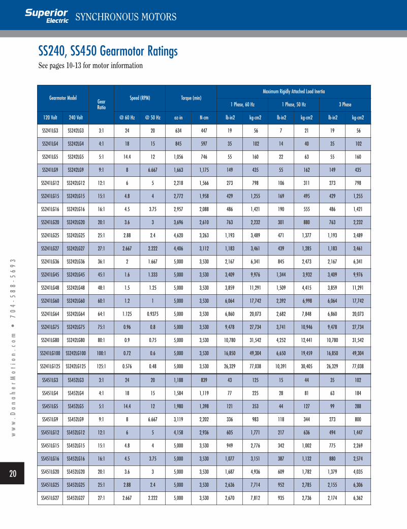
SS240, SS450 Gearmotor RatingsSee pages 10-13 for motor information
ww
w.D
an
ah
er
Mo
tio
n.c
om
•
7
04
-5
88
-5
69
3SYNCHRONOUS MOTORS
Gearmotor Model Gear Ratio
Speed (RPM) Torque (min)Maximum Rigidly Attached Load Inertia
1 Phase, 60 Hz 1 Phase, 50 Hz 3 Phase
120 Volt 240 Volt @ 60 Hz @ 50 Hz oz-in N-cm lb-in2 kg-cm2 lb-in2 kg-cm2 lb-in2 kg-cm2
SS241LG3 SS242LG3 3:1 24 20 634 447 19 56 7 21 19 56
SS241LG4 SS242LG4 4:1 18 15 845 597 35 102 14 40 35 102
SS241LG5 SS242LG5 5:1 14.4 12 1,056 746 55 160 22 63 55 160
SS241LG9 SS242LG9 9:1 8 6.667 1,663 1,175 149 435 55 162 149 435
SS241LG12 SS242LG12 12:1 6 5 2,218 1,566 273 798 106 311 273 798
SS241LG15 SS242LG15 15:1 4.8 4 2,772 1,958 429 1,255 169 495 429 1,255
SS241LG16 SS242LG16 16:1 4.5 3.75 2,957 2,088 486 1,421 190 555 486 1,421
SS241LG20 SS242LG20 20:1 3.6 3 3,696 2,610 763 2,232 301 880 763 2,232
SS241LG25 SS242LG25 25:1 2.88 2.4 4,620 3,263 1,193 3,489 471 1,377 1,193 3,489
SS241LG27 SS242LG27 27:1 2.667 2.222 4,406 3,112 1,183 3,461 439 1,285 1,183 3,461
SS241LG36 SS242LG36 36:1 2 1.667 5,000 3,530 2,167 6,341 845 2,473 2,167 6,341
SS241LG45 SS242LG45 45:1 1.6 1.333 5,000 3,530 3,409 9,976 1,344 3,932 3,409 9,976
SS241LG48 SS242LG48 48:1 1.5 1.25 5,000 3,530 3,859 11,291 1,509 4,415 3,859 11,291
SS241LG60 SS242LG60 60:1 1.2 1 5,000 3,530 6,064 17,742 2,392 6,998 6,064 17,742
SS241LG64 SS242LG64 64:1 1.125 0.9375 5,000 3,530 6,860 20,073 2,682 7,848 6,860 20,073
SS241LG75 SS242LG75 75:1 0.96 0.8 5,000 3,530 9,478 27,734 3,741 10,946 9,478 27,734
SS241LG80 SS242LG80 80:1 0.9 0.75 5,000 3,530 10,780 31,542 4,252 12,441 10,780 31,542
SS241LG100 SS242LG100 100:1 0.72 0.6 5,000 3,530 16,850 49,304 6,650 19,459 16,850 49,304
SS241LG125 SS242LG125 125:1 0.576 0.48 5,000 3,530 26,329 77,038 10,391 30,405 26,329 77,038
SS451LG3 SS452LG3 3:1 24 20 1,188 839 43 125 15 44 35 102
SS451LG4 SS452LG4 4:1 18 15 1,584 1,119 77 225 28 81 63 184
SS451LG5 SS452LG5 5:1 14.4 12 1,980 1,398 121 353 44 127 99 288
SS451LG9 SS452LG9 9:1 8 6.667 3,119 2,202 336 983 118 344 273 800
SS451LG12 SS452LG12 12:1 6 5 4,158 2,936 605 1,771 217 636 494 1,447
SS451LG15 SS452LG15 15:1 4.8 4 5,000 3,530 949 2,776 342 1,002 775 2,269
SS451LG16 SS452LG16 16:1 4.5 3.75 5,000 3,530 1,077 3,151 387 1,132 880 2,574
SS451LG20 SS452LG20 20:1 3.6 3 5,000 3,530 1,687 4,936 609 1,782 1,379 4,035
SS451LG25 SS452LG25 25:1 2.88 2.4 5,000 3,530 2,636 7,714 952 2,785 2,155 6,306
SS451LG27 SS452LG27 27:1 2.667 2.222 5,000 3,530 2,670 7,812 935 2,736 2,174 6,362

RED
BLACKWHITE
INPUTLINE
CONTROLSWITCH
CWOFFCCW
MOTOR
1
2
3
SWITCH PROTECTION NETWORK FORAC OPERATION OF STANDARD MODELS
21
ww
w.D
an
ah
er
Mo
tio
n.c
om
•
7
04
-5
88
-5
69
3
App l i ca t ion Ass i s tanceParallel Motor OperationTwo or more Superior motors may be operated simultaneously fromthe same power source, if the total current requirement does notexceed the current capability of the supply. However, due to the motorstarting characteristics, mechanical synchronization of the motors isnot practical. As described under Starting And StoppingCharacteristics, one motor may achieve running speed within 5milliseconds while a second motor, because of its at rest position, mayrequire 25 milliseconds to achieve running speed.
Starting High Inertia LoadsThe motor charts show the maximum load inertia that each motormodel can start. Inertial loads as high as five to ten times theseratings can be started if a flexible coupling is used between the motorshaft and the load. The coupling should allow approximately 5° ofshaft rotation before the full load is applied to the shaft. Rubbercouplings are often used, as are chain drives with sufficient slack toallow the necessary shaft motion. Timing belts are also used, and inmost cases will provide adequate flexing while providing smooth andquiet transmission of power.
Effects of Speed Reduction Gearing onTorque and InertiaThe combination of reduction gearing and a Superior motor providesincreased torque as well as a lower operating speed. Output speed isdecreased and torque increased by the factor of the gear ratio usedminus losses due to gear train inefficiency. Gear losses are typicallyaround 10% per mesh. Step-down gearing offers even greater gains ininertial load rating, since the inertia moving capability increases by thesquare of the gear ratio. Timing belts and pulleys can be used in placeof gears for speed reduction and will provide the added benefit of aflexible coupling.
Coupling Motor to LoadBecause of the extremely fast starting and stopping characteristics of a Superior AC synchronous motor, couplings, pulleys or other devices should be well secured to the motor shaft with the key provided, roll-pins, or set-screws.
If a coupling is to be press-fitted to the shaft, the motor must be held by the shaft (not by the gearbox or the motor case) when pressing the coupling in place. This will prevent damage to the motor bearings. The force used in pressing must not exceed the thrust force limit of the gearbox (100 pounds).
Switch Contact ProtectionIn some applications it may be desirable to protect the switch contactsfrom arcing and from transient voltages generated during switching.The most common method is the addition of resistors and capacitorsacross the switch contacts as shown in the diagram. Recommendedvalues of the components are: resistor, 330 ohm, 1 watt; capacitor, 0.1mfd, 250 Vac.
Temperature ConsiderationsThe motors are rated for a maximum free-air ambient temperature of40° C (104° F). However, it is possible to operate in higher ambienttemperatures or above rated voltages if the motors are mounted onmetal plates or are forced-air cooled. Do not exceed the maximummotor case temperature of 100° C (212º F).
Maximum Shaft Loads
SYNCHRONOUS MOTORS
Motor Series
Maximum Shaft Loads
Radiallb kg
Axiallb kg
KS06 15 6.8 25 11
KS09 25 11 50 23
KS09 Gearmotors 150 68 100 45
KS11 75 34 130 59
SS240, SS450 25 11 50 23
SS240, SS450 Gearmotors 150 68 100 45
X250, XCE250 25 11 50 23
X700, XCE700 25 11 50 23
X1100, XCE1100 50 23 100 45
X1500, XCE1500 50 23 100 45

22
ww
w.D
an
ah
er
Mo
tio
n.c
om
•
7
04
-5
88
-5
69
3SYNCHRONOUS MOTORS
Application Assistance (continued)
How to Select an AC MotorTo select a synchronous motor first determine the torque and moment of inertia characteristics of the load, as presenteed to the motor. The followingexamples show how to calculate these requirements in both standard U.S. andmetric units.
Once the requirements of the application including input voltage andfrequency are known, refer to the ratings shown on the motor charts andselect the motor which best suits these requirements.
If additional information or technical assistance is needed, contact Superior Electric. A representative will be pleased to help you select the bestmotor for your application.
Gears and PulleysWhen the load is driven through gears or pulleys, the required motor torque ischanged by the overall ratio.
For example, if the load is 90 ounce-inches (63.6 Ncm) and the step-downratio is 3:1, the required torque would be 30 ounce-inches (21.2 Ncm).
Load inertia presented to the motor is changed by the square of the ratio.For example, with a load inertia of 4 pound-inches2 (11.71 kg-cm2) and a 2:1step-down ratio, the effective inertia would be 1 pound-inch2 (2.93 kg-cm2)plus the inertia of the first gear or pulley.
Torque InertiaTorque (oz-in) = FrWhere F = Force (in ounces) required to drive the load
r = Radius (in inches)Force can be measured using a pull type spring scale. The scale may beattached to a string that is wrapped around a pulley or a hand wheelattached to the scale. If the scale reading is in pounds, it must beconverted into ounces to obtain a torque rating in ounce-inches.
For example: A 4” diameter pulley requires a 2 pound pull on the scale to rotate it.
F = 2 pounds x 16 = 32 ouncesr = 4" ÷ 2 = 2"Torque = 32 x 2 = 64 oz-in
Torque (Ncm) = FrWhere F = Force (N) required to drive the load
r = radius (in cm)Force can be measured using a pull type spring scale. If the scalereading is calibrated in kilograms, the scale reading must be multipliedby 9.8067 to obtain newtons. The scale should be attached to a stringthat is wrapped around a pulley or a hand wheel which is then attachedto the load.
For example, a 10 cm diameter pulley requires a 1.5 newton (0.153 kg)pull on the scale to rotate it.
F = 1.5 newtonsr = 5 cmTorque = 1.5 x 5 = 7.5 Ncm
Moment of Inertia (lb-in2)
Where W = Weight in poundsr = Radius in inches
For example: A load is a 8” diameter gear weighing 8 ouncesW = 8 ÷ 16 = .05 poundsr = 8" ÷ 2 = 4"
Moment Of Inertia (kg-cm2)
Where W = newtonsr = cm
For example: A load is a 20 cm diameter gear weighing 0.25 newtons.W = .25 newtonsr = 10 cm
W
r
r W
F
r1 r2
(lb-in2) = for a diskWr2
2or (lb-in2) = (r1 - r2) for a cylinder
W
2
Moment Of Inertia = = 4 lb-in20.5 x (4)2
2
J = for a diskWr2
19.6134or J = for a cylinder
W (r1 - r2)
19.6134
Moment Of Inertia = = 1.275 kg-cm20.25 x 102
19.6134

23
ww
w.D
an
ah
er
Mo
tio
n.c
om
•
7
04
-5
88
-5
69
3
Convers ion Fac tors
SYNCHRONOUS MOTORS
BA mm cm m inch feet
mm ===== 0.1 0.001 0.03937 0.003281
cm 10 ===== 0.01 0.3937 0.03281
m 1000 100 ===== 39.37 3.281
inch 25.4 2.54 0.0254 ===== 0.08333feet 304.8 30.48 0.3048 12 =====
Length* Force*B
A g kg oz lb Newton
g ===== 0.001 0.03527 0.002205 0.0098
kg 1000 ===== 35.27 2.205 9.807
oz 28.35 0.02835 ===== 0.0625 0.278
lb 453.6 0.4536 16 ===== 4.448Newton 102 0.102 3.597 0.2248 =====
BA kgm kgcm gcm oz-in oz-in-sec lb-in lb-in-sec lb-ft lb-ft-sec
(slug ft)kgm ===== 1.00 x 10⁴ 1.00 x 10⁷ 5.467 x 10⁴ 1.416 x 10² 3.418 x 10³ 8.851 23.73 7.376 x 10⁻¹
kgcm 1.00 x 10-4 ===== 1.00 x 10³ 5.457 1.416 x 10⁻² 3.418 x 10⁻¹ 8.851 x 10⁻⁴ 2.373 x 10⁻³ 7.376 x 10⁻⁵
gcm 1.00 x 10⁻⁷ 1.00 x 10-3 ===== 5.467 x 10⁻³ 1.416 x 10⁻⁵ 3.418 x 10⁻⁴ 8.851 x 10⁻⁷ 2.373 x 10⁻⁶ 7.376
oz-in 1.829 x 10⁻⁵ 1.829 x 10⁻¹ 1.829 x 102 ===== 2.590 x 10⁻³ 6.250 x 10⁻² 1.619 x 10⁻⁴ 4.340 x 10⁻⁴ 1.349 x 10⁻⁵
oz-in-sec 7.062 x 10⁻³ 70.61 7.062 x 10⁴ 3.861 x 102 ===== 24.13 6.250 x 10⁻² 1.676 x 10⁻¹ 5.208 x 10⁻³
lb-in 2.926 x 10⁻⁴ 2.926 2.926 x 10³ 1.600 x 10⁻¹ 4.144 x 10-2 ===== 2.590 x 10⁻³ 6.944 x 10⁻³ 2.158 x 10⁻⁴
lb-in-sec 1.130 x 10⁻¹ 1.130 x 10³ 1.130 x 10⁶ 6.177 x 10³ 16 3.861 x 102 ===== 2.681 8.333 x 10⁻²
lb-ft 4.214 x 10⁻² 4.214 x 10² 4.214 x 10⁵ 2.304 x 10³ 5.968 1.440 x 10² 3.730 x 10-1 ===== 3.180 x 10⁻²
lb-ft-sec(slug ft) 1.356 1.356 x 10⁴ 1.356 x 10⁷ 7.413 x 10⁴ 1.920 x 10² 4.633 x 10⁵ 12 32.17 =====
Inertia*
BA Nm Ncm dyn cm kgm* kgcm* gcm* oz-in lb-ft lb-in
Nm ===== 1.00 x 10² 1.000 x 10⁷ 1.020 x 10⁻¹ 10.20 1.020 x 10⁴ 1.416 x 10² 7.376 x 10⁻¹ 8.851
Ncm 1.000 x 10-2 ===== 1.000 x 10⁵ 1.020 x 10⁻³ 1.020 x 10⁻¹ 1.020 x 10² 1.416 7.376 x 10⁻³ 8.851 x 10⁻²
dyn cm 1.000 x 10⁻⁷ 1.000 x 10-5 ===== 1.020 x 10⁻⁸ 1.020 x 10⁻⁶ 1.020x 10⁻³ 1.416 x 10⁻⁵ 7.376 x 10⁻⁸ 8.851 x 10⁻⁷
kgm** 9.807 9.807 x 10² 9.807 x 107 ===== 1.000 x 10² 1.000 x 10⁵ 1.389 x 10³ 7.233 86.80
kgcm** 9.807 x 10⁻² 9.807 9.807 x 10⁵ 1.000 x 10-2 ===== 1.000 x 10³ 13.89 7.233 x 10⁻² 8.680 x 10⁻¹
gcm** 9.807 x 10⁻⁵ 9.807 x 10⁻³ 9.807 x 10² 1.000 x 10⁻⁵ 1.000 x 10-3 ===== 1.389 x 10⁻² 7.233 x 10⁻⁵ 8.680 x 10⁻⁴
oz-in 7.062 x 10⁻³ 7.062 x 10⁻¹ 7.062 x 10⁴ 7.201 x 10⁻⁴ 7.201 x 10⁻² 72.01 ===== 5.283 x 10⁻³ 6.250 x 10⁻²
lb-ft 1.356 1.356 x 10² 1.356 x 10⁷ 1.383 x 10⁻¹ 13.83 1.383 x 10⁴ 1.920 x 102 ===== 12
lb-in 1.130 x 10⁻¹ 11.30 1.130 x 10⁶ 1.152 x 10⁻² 1.152 1.152 x 10³ 16 8.330 x 10-2 =====
Torque*
* Multiply units of "A" by indicated factor to obtain units of "B". * Multiply units of "A" by indicated factor to obtain units of "B".
* Multiply units of "A" by indicated factor to obtain units of "B".
* Multiply units of "A" by indicated factor to obtain units of "B".** Sometimes written as kpm, kpcm, and pcm, respectively, to denote the force equivalent of the kg and g mass.

Distribution Coast-To-Coast and International
The Superior Electric brand is a global leader inthe engineering, manufacturing, and marketing
of precision motion and control products forindustrial applications. All Superior motorsand controls are backed by highly specialized
engineers and service people who can help solveyour production challenges. Superior Electric’s
capabilities and products have improvedoperations for companies around the world.
Through Danaher Motion's extensive authorizeddistributor network, Superior Electric products
are available worldwide. These distributorsprovide convenient services by offering technical
support, replacement parts, and literature, aswell as an extensive inventory of models off-the-
shelf for the fastest possible delivery. Call Superior Electric customer service for
ordering and application information or for theaddress of the nearest authorized distributor for
Superior Electric products.
13500-J South Point Blvd. • Charlotte, NC 28273 U.S.A.TEL: 704-588-5693 • FAX: 704-588-5695
www.DanaherMotion.com
© 2003 Superior Electric- Printed in U.S.A. SP-15,000-08/2003 SUP-01-02-S101
Danaher MotionCustomer Support Center13500-J South Point Blvd.Charlotte, NC 28273Tel: 704-588-5693Fax: 704-588-5695Support email: [email protected]: www.DanaherMotion.com
In EuropeDanaher Motion GmbH & Co. KGRobert-Bosch-Straße 1064331 Weiterstadt, GermanyTel: +49 (0) 6151-8796-10 Fax: +49 (0) 6151-8796-123Internet: www.DanaherMotion.de


