Tab44.fm Page 1 Monday, September 22, 2008 9:04 PM
July 2008
H-2
For more information visit:
www.EatonCanada.ca
CA08102002K
Control Transformers
H
Type MTA
Type MTA
Type MTA Transformer
Product Description
■
Varnish impregnated core and coil design.
■
Suitable for indoor applications.
■
Open core and coil design.
Application Description
Machine Tool and Industrial Control Transformers provide stepped-down voltages to machine tool control devices enabling control circuits to be isolated from all power and lighting circuits. This allows the use of ground-ed or ungrounded circuits that are independent of the power or lighting grounds; greater safety is afforded the operator. The control transformer line is particularly adaptable on applica-tions where compact construction is demanded.
Features, Benefits and Functions
■
UL recognized component for units rated 1000 VA and below.
■
CSA certified for units rated 1000 VA and below.
■
55ºC rise, 105ºC insulation system.
■
60 Hz operation standard.
■
100% tested to verify product quality.
■
Performance equals or exceeds requirements of ANSI/NEMA ST-1.
■
Regulation exceeds ANSI/NEMA requirements for all ratings.
■
Each unit must pass rigid tests for turns ratio, insulation, continuity, and over potential.
■
50 – 5000 VA ratings.
Standards and Certifications
Industry Standards
All Cutler-Hammer dry-type distribution and control transformers by Eaton Corporation are built and tested in accordance with applicable NEMA, ANSI and IEEE Standards.
Product Specifications
Frequency
Cutler-Hammer Type MTA control transformers are designed for 60 Hertz operation. Transformers required for other frequencies are available and must be specifically designed.
Insulation System and Temperature Rise
Industry standards classify insulation systems and rise as shown below:
Table H-1. Insulation System Classification
The design life of transformers having different insulation systems is the same — the lower temperature systems are designed for the same life as the higher temperature systems.
Series-Multiple Windings
Series-multiple windings consist of 2 similar coils in each winding which can be connected in series or parallel (multiple). Transformers with series-multiple windings are designated with an “X” or “/” between the voltage ratings, such as voltages of “120/240” or “240 X 480.” If the series-multiple winding is designated by an “X,” the winding can be connected only for a series or parallel. With the “/” designa-tion, a mid-point also becomes avail-able in addition to the series or parallel connection. As an example, a 120 X 240 winding can be connected for either 120 (parallel) or 240 (series), but a 120/240 winding can be connected for 120 (parallel), or 240 (series), or 240 with a 120 mid-point.
The following pages provide listings for most standard transformer ratings and styles.
For other ratings or styles not shown, refer to Eaton.
Ambient + WindingRise
+HotSpot
=Temp. Class
40°C40°C40°C40°C
55°C 80°C115°C150°C
10°C30°C30°C30°C
105°C150°C185°C220°C
Tab44.fm Page 2 Monday, September 22, 2008 9:04 PM
July 2008
CA08102002K For more information visit:
www.EatonCanada.ca
H-3Control Transformers
H
Type MTA
Overcurrent Protection Tables
Overcurrent protection on both the primary and secondary sides of transformers are specified in UL 508 and the National Elec-trical Code. The maximum acceptable ratings are shown below. Due to high inrush currents present when a transformer is initially energized, it is recommended that the primary fuse be time delay to prevent nuisance trips during startup.
Table H-2. Maximum Acceptable Rating of Primary Overcurrent Protection
Note:
If the rated primary current is less than 2 amperes, the maximum rating of the overcurrent device is 300% for power circuits, shown above, or 500% for control circuits, shown above (in brackets). If the rated primary current is 2 amperes or more, the maximum rating of the overcurrent device is 250%. All figures assume secondary overcurrent protection per NEC/UL. References: NEC 430-72 (c) exception 2, 450-3 (b) 1 & 2, UL 508 32.7, UL 845 11.16 and 11.17.
Table H-3. Maximum Acceptable Rating of Secondary Overcurrent Protection
Note:
If the rated secondary current is less than 9 amperes, the maximum rating of the overcurrent device is 167%; 9 amperes or more, the maximum rating of the overcurrent device is 125%. If 125% does not correspond to a standard fuse rating, the next highest standard rating may be used.References: NEC 430-72 (c) exception 2, 450-3 (b) 1 & 2, UL 508 32.7, UL 845 11.16 and 11.17.
Tab44.fm Page 6 Monday, September 22, 2008 9:04 PM
July 2008
CA08102002K For more information visit:
www.EatonCanada.ca
H-7Control Transformers
H
Type MTC
Type MTC
Type MTC Transformers
Product Description
■
Varnish impregnated core and coil design.
■
Suitable for indoor applications.
Application Description
Transformers provide stepped down voltages to machine tool control devices enabling control circuits to be isolated from all power and lighting circuits. This allows the use of grounded or ungrounded circuits that are independent of the power or light-ing grounds; greater safety is afforded the operator. The control transformer line is particularly adaptable on appli-cations where compact construction is demanded. The MTC line is similar to the MTA line except it provides increased regulation.
Features, Benefits and Functions
■
Designed specifically for loads requiring extremely good regulation — 10% – 200% better regulation than Type MTA.
■
UL recognized component for units rated 1000 VA and below.
■
CSA certified for units rated 1000 VA and below.
■
50/60 Hz operation standard.
■
100% tested to verify product quality.
■
Each unit must pass rigid tests for turns ratio, insulation, continuity, and over potential.
■
Performance equals or exceeds requirements of ANSI/NEMA ST-1.
■
Regulation exceeds ANSI/NEMA requirements for all ratings.
■
50
–
5000 VA ratings.
■
55ºC rise, 105ºC insulation system.
Standards and Certifications
Industry Standards
All Cutler-Hammer dry-type distribution and control transformers by Eaton Corporation are built and tested in accordance with applicable NEMA, ANSI and IEEE Standards.
Product Specifications
Frequency
Cutler-Hammer standard dry-type dis-tribution transformers are designed for 60 Hz operation. Transformers required for other frequencies are available and must be specifically designed.
Insulation System and Temperature Rise
Industry standards classify insulation systems and rise as shown below:
Table H-11. Insulation System Classification
The design life of transformers having different insulation systems is the same — the lower temperature systems are designed for the same life as the higher temperature systems.
Series-Multiple Windings
Series-multiple windings consist of 2 similar coils in each winding which can be connected in series or parallel (mul-tiple). Transformers with series-multi-ple windings are designated with an “X” or “/” between the voltage ratings, such as voltages of “120/240” or “240 X 480.” If the series-multiple winding is designated by an “X,” the winding can be connected only for a series or parallel. With the “/” designa-tion, a mid-point also becomes avail-able in addition to the series or parallel connection. As an example, a 120 X 240 winding can be connected for either 120 (parallel) or 240 (series), but a 120/240 winding can be connected for 120 (parallel), or 240 (series), or 240 with a 120 mid-point.
The following pages provide listings for most standard transformer ratings and styles.
For other ratings or styles not shown, refer to Eaton.
Ambient + WindingRise
+HotSpot
=Temp. Class
40°C40°C40°C40°C
55°C 80°C115°C150°C
10°C30°C30°C30°C
105°C150°C185°C220°C
Tab44.fm Page 7 Monday, September 22, 2008 9:04 PM
July 2008
H-8
For more information visit:
www.EatonCanada.ca
CA08102002K
Control Transformers
H
Industrial Control Transformers
Type MTC
Product Selection
Table H-12. Type MTC
�
See
Page H-4
for Wiring Diagrams.
Note:
For additional information, refer to the Cutler-Hammer Industrial Control Transformer Binder B1228A.
Table H-13. Type MTC with Integrally Mounted 30 Amperes, 600 volt Class with 2-Pole Primary Fuse Block for Rejection Type Fuses (Fuses Not Included)
�
See
Page H-4
for Wiring Diagrams.
Note:
For additional information, refer to the Cutler-Hammer Industrial Control Transformer Binder B1228A.
VA Dimensions (Inches) WeightLbs.
Dimensions (mm) Weightkg
Frame WiringDiagram
�
StyleNumber
Price
Height Width Depth Height Width Depth
240/480 Volts to 120 Volts, 60 Hz230/460 Volts to 115 Volts, 50/60 Hz220/440 Volts to 110 Volts, 50/60 Hz
50 75 100
2-19/322-19/322-7/8
333-3/8
3-3/4 3-3/4 4
2 3 3
66 66 73
76 76 86
95 95102
.9 1.4 1.4
FR1310FR1314FR1413
111
C0050C2AC0075C2AC0100C2A
150 200 250
3-3/163-13/163-13/16
3-3/44-1/24-1/2
4-3/4 4-1/2 5
6 7 8
81 97 97
95114114
121114127
2.7 3.2 3.6
FR1517FR1714FR1717
111
C0150C2AC0200C2AC0250C2A
300 350 500
3-13/163-13/164-3/8
4-1/24-1/25-1/4
5-3/8 6 6-1/8
101120
97 97111
114114133
137152156
4.5 5.0 9.1
FR1722FR1726FR1931
111
C0300C2AC0350C2AC0500C2A
75010001500
4-3/85-7/166-1/8
5-1/46-3/86-7/8
7-3/4 7-1/2 8-3/8
283435
111138156
133162175
197191213
12.715.415.9
FR1934FR2236FRC822
111
C0750C2AC1000C2AC1500C2A
200030005000
67-3/87-7/8
6-3/48-7/168-11/16
8-1/2 8-3/411
385382
152187200
171214221
216222279
17.324.137.2
FRC823FRC824FRC825
111
C2000C2AC3000C2AC5000C2A
VA Dimensions (Inches) WeightLbs.
Dimensions (mm) Weightkg
Frame WiringDiagram
�
StyleNumber
Price
Height Width Depth Height Width Depth
240/480 Volts to 120 Volts, 60 Hz230/460 Volts to 115 Volts, 50/60 Hz220/440 Volts to 110 Volts, 50/60 Hz
Tab44.fm Page 8 Monday, September 22, 2008 9:04 PM
July 2008
CA08102002K For more information visit:
www.EatonCanada.ca
H-9Control Transformers
H
Industrial Control Transformers
Type MTE
Type MTE
Type MTE Transformers
Product Description
■
Epoxy-encapsulated coils.
Application Description
Transformers provide stepped down voltages to machine tool control devices enabling control circuits to be isolated from all power and lighting circuits. This allows the use of grounded or ungrounded circuits that are independent of the power or light-ing grounds; greater safety is afforded the operator. The control transformer line is particularly adaptable on appli-cations where compact construction is demanded.
Note:
The MTG, “open core-coil design” has been superseded by the epoxy-encapsulated core-coil design MTE with no change to dimensions or functionality.
Features, Benefits and Functions
■
UL listed.
■
CSA certified.
■
Epoxy encapsulated.
■
Laminations of high quality silicon steel to minimize core losses and optimize performance.
■
Copper magnet wire for high quality, efficient operation.
■
Secondary fuse clips where applicable.
■
Optional primary fusing.
■
Molded in terminals.
■
50/60 Hz operation.
■
55°C rise, 105ºC insulation system.
■
Performance meets/exceeds requirements of ANSI/NEMA ST-1.
■
Regulation exceeds ANSI/NEMA requirements for all ratings.
■
25
–
1500 VA ratings.
■
Moulded-in terminals for maximum durability.
Standards and Certifications
Industry Standards
All Cutler-Hammer dry-type distribution and control transformers by Eaton Corporation are built and tested in accordance with applicable NEMA, ANSI, and IEEE Standards. All 600 volt class transformers are UL listed unless otherwise noted.
Options and Accessories
Primary Fuse Kit
The primary fuse kit includes a 2-pole class CC fuse block, instructions, and all associated mounting and wiring hardware. Fuses are not included. When installed, the primary fuse kit will add a maximum of 11/16 inch to the transformer depth and 1-15/16 inches to the transformer height.
Table H-14. Primary Fuse Kit
Note:
1000 VA and larger are Class 130°C Insulation System.
Tab44.fm Page 9 Monday, September 22, 2008 9:04 PM
July 2008
H-10
For more information visit:
www.EatonCanada.ca
CA08102002K
Control Transformers
H
Type MTE
Product Specifications
Insulation System and Temperature Rise
Industry standards classify insulation systems and rise as shown below:
Table H-17. Insulation System Classification
The design life of transformers having different insulation systems is the same — the lower temperature systems are designed for the same life as the higher temperature systems.
Series-Multiple Windings
Series-multiple windings consist of 2 similar coils in each winding which can be connected in series or parallel (multiple). Transformers with series-multiple windings are designated with an “X” or “/” between the voltage ratings, such as voltages of “120/240” or “240 X 480.” If the series-multiple winding is designated by an “X,” the winding can be connected only for a series or parallel. With the “/” designa-tion, a mid-point also becomes avail-able in addition to the series or parallel connection. As an example, a 120 X 240 winding can be connected for either 120 (parallel) or 240 (series), but a 120/240 winding can be connected for 120 (parallel), or 240 (series), or 240 with a 120 mid-point.
Ambient + WindingRise
+HotSpot
=Temp. Class
40°C40°C40°C40°C
55°C 80°C115°C150°C
10°C30°C30°C30°C
105°C150°C185°C220°C
Wiring Diagrams
Figure H-6. Diagram 1
Figure H-7. Diagram 2
Figure H-8. Diagram 3
Figure H-9. Diagram 4
Figure H-10. Diagram 5
Figure H-11. Diagram 6
Tab44.fm Page 10 Monday, September 22, 2008 9:04 PM
July 2008
CA08102002K For more information visit:
www.EatonCanada.ca
H-11Control Transformers
H
Type MTE
Wiring Diagrams
Figure H-12. Diagram 7
Figure H-13. Diagram 8
Figure H-14. Diagram 9
Figure H-15. Diagram 10
Figure H-16. Diagram 11
Figure H-17. Diagram 12
Figure H-18. Diagram 13
Figure H-19. Diagram 14
Figure H-20. Diagram 15
Figure H-21. Diagram 16
H1 H3 H2 H4 H1 H3 H2 H4
H1 H3 H2 H4
X4 X2 X3 X1
X4 X2 X3 X1 X4 X2 X3 X1
240 V 480 V
240 V120 V
H1 H2
X2 X1
600 V575 V550 V
24 V23 V22 V
H1 H2
X2 X1
420 V400 V380 V
24 V23 V22 V
H1 H2 H3 H4 H5
X3 X2 X1
550,
575,
600
V
440,
460,
480
V
380,
400,
416
V
220,
230,
240
V
23/2
4/25
110,
115,
120
V
0 V
0 V
X4 X3 X2 X1
H1 H2 H3 H4 H5 H6
575
V
460
V
400
V
230
V
208
V
0 V
0 V
24V
115
V
230
V
X4 X3 X2 X1
H1 H2 H3 H4 H5 H657
5 V
460
V
400
V
230
V
208
V
0 V
0 V
0 V
115
V
115
V
Tab44.fm Page 11 Monday, September 22, 2008 9:04 PM
July 2008
H-12
For more information visit:
www.EatonCanada.ca
CA08102002K
Control Transformers
H
Type MTE
Product Selection
Table H-18. Type MTE — Product Selection
�
See
Page H-10
for Wiring Diagrams.
Note:
For additional information, refer to the Cutler-Hammer Industrial Control Transformer Binder B1228A.
VA Dimensions (Inches) WeightLbs.
Dimensions (mm) Weightkg
WiringDiagram
�
StyleNumber
Price
Height Width Depth Height Width Depth
Primary: 240 x 480, 230 x 460, 220 x 440 with JumpersSecondary: 120/115/110 with Fuse Clips for 13/32 x 1-1/2 Fuses
25 50 75 100
2-9/162-9/162-9/162-7/8
3333-3/8
2-1/233-1/23-3/8
1.7 2.6 3.5 4.2
65 65 65 73
76 76 76 86
64 76 89 86
.8 1.2 1.6 1.9
1111
C0025E2AC0050E2AC0075E2AC0100E2A
150 200 250
3-3/163-13/163-13/16
3-3/44-1/24-1/2
44 4-3/8
6.7 8.510.0
81 97 97
95114114
102102111
3.0 3.9 4.5
111
C0150E2AC0200E2AC0250E2A
300 350 500
3-13/163-13/164-3/4
4-1/24-1/25-1/4
4-3/45-1/45-1/2
11.313.619.2
97 97121
114114133
121133140
5.1 6.2 8.7
111
C0300E2AC0350E2AC0500E2A
75010001500
4-3/45-11/166-3/8
5-1/46-3/47-1/2
76-7/167-3/8
28.129.540.0
121144162
133171191
178164187
12.813.418.1
111
C0750E2AC1000E2AC1500E2A
Primary: 240 x 480 with JumpersSecondary: 24 with Fuse Clips for 13/32 x 1-1/2 Fuses (through 500 VA)
50 75 100 150
2-9/162-9/162-7/83-3/16
333-3/83-3/4
33-1/23-3/84
2.7 3.5 4.2 6.7
65 65 73 81
76 76 86 95
76 89 86102
1.2 1.6 1.9 3.0
2222
C0050E2BC0075E2BC0100E2BC0150E2B
200 250 300
3-13/163-13/163-13/16
4-1/24-1/24-1/2
4 4-3/84-3/4
8.510.111.4
97 97 97
114114114
102111121
3.9 4.6 5.2
222
C0200E2BC0250E2BC0300E2B
350 500 750
3-13/164-3/44-3/4
4-1/25-1/45-1/4
5-1/45-5/87
13.417.528.1
97121121
114133133
133143178
6.1 7.912.8
222
C0350E2BC0500E2BC0750E2B
Primary: 120 x 240 with JumpersSecondary: 24 with Fuse Clips for 13/32 x 1-1/2 Fuses
50 75 100
2-9/162-9/162-7/8
333-3/8
33-1/23-3/8
2.6 3.6 4.4
65 65 73
76 76 86
76 89 56
1.2 1.6 2.0
333
C0050E1BC0075E1BC0100E1B
150 200 250
3-3/163-13/163-13/16
3-3/44-1/24-1/2
444-3/8
6.7 8.310.1
81 97 97
95114114
102102111
3.0 3.8 4.6
333
C0150E1BC0200E1BC0250E1B
300 350 500
3-13/163-13/164-3/4
4-1/24-1/25-1/4
4-3/45-1/45-5/8
11.213.217.5
97 97121
114114133
121133143
5.1 6.0 7.9
333
C0300E1BC0350E1BC0500E1B
Primary: 208/277Secondary: 120 with Fuse Clips for 13/32 x 1-1/2 Fuses
50 75 100 150
2-9/162-9/162-7/83-3/16
333-3/83-3/4
33-1/23-3/84
2.9 3.8 4.5 6.9
65 65 73 81
76 76 86 95
76 89 86102
1.3 1.7 2.0 3.1
4444
C0050E3AC0075E3AC0100E3AC0150E3A
200 250 300
3-13/163-13/163-13/16
4-1/24-1/24-1/2
4 4-3/84-3/4
8.710.211.4
97 97 97
114114114
102111121
3.9 4.6 5.2
444
C0200E3AC0250E3AC0300E3A
350 500 750
3-13/164-3/44-3/4
4-1/25-1/45-1/4
5-1/45-3/87
13.717.225.7
97121121
114133133
133136178
6.2 7.811.7
444
C0350E3AC0500E3AC0750E3A
For other ratings or styles not shown, refer to Eaton.
Tab44.fm Page 12 Monday, September 22, 2008 9:04 PM
July 2008
CA08102002K For more information visit:
www.EatonCanada.ca
H-13Control Transformers
H
Type MTE
Table H-19. Type MTE — Product Selection
�
See
Page H-11 for Wiring Diagrams.� Secondary fuse clips are not available on this Catalogue number.Note: For additional information, refer to the Cutler-Hammer Industrial Control Transformer Binder B1228A.
VA Dimensions (Inches) WeightLbs.
Dimensions (mm) Weightkg
WiringDiagram �
StyleNumber
Price
Height Width Depth Height Width Depth
Primary: 240 x 480 with JumpersSecondary: 120 x 240 with Jumpers, Secondary Fuse Clips not Applicable 50 75100150
2-9/162-9/162-7/83-3/16
333-3/83-3/4
33-1/23-3/84
2.6 3.5 4.2 6.7
65 65 73 81
76 76 86 95
76 89 86102
1.2 1.6 1.9 3.1
11111111
C0050E2CXXC0075E2CXXC0100E2CXXC0150E2CXX
200250300
3-13/163-13/163-13/16
4-1/24-1/24-1/2
44-3/84-7/8
8.510.011.8
97 97 97
114114114
102111124
3.9 4.6 5.4
111111
C0200E2CXXC0250E2CXXC0300E2CXX
350500750
3-13/164-3/44-3/4
4-1/25-1/45-1/4
5-1/45-1/47
13.617.526.4
97121121
114133133
133133178
6.2 8.012.0
111111
C0350E2CXXC0500E2CXXC0750E2CXX
Primary: 550/575/600Secondary: 110/115/120 with for 13/32 x 1-1/2 Fuses 50 75100150
2-9/162-9/162-7/83-3/16
333-3/83-3/4
33-1/23-3/84
2.7 3.6 4.2 6.8
65 65 73 81
76 76 86 95
76 89 86102
1.2 1.6 1.9 3.1
10101010
C0050E4CC0075E4CC0100E4CC0150E4C
200250300
3-13/163-13/163-13/16
4-1/24-1/24-1/2
44-3/84-3/4
8.410.011.3
97 97 97
114114114
102111121
3.8 4.6 5.1
101010
C0200E4CC0250E4CC0300E4C
350500750
3-13/164-3/44-3/4
4-1/25-1/45-1/4
5-1/45-3/87
13.616.825.7
97121121
114133133
133137178
6.2 7.611.7
101010
C0350E4CC0500E4CC0750E4C
Primary: 380/400/415Secondary: 22/23/24 with Fuse Clips for 13/32 x 1-1/2 Fuses 50 75100
2-9/162-9/162-7/8
333-3/8
33-1/23-3/8
2.5 3.5 4.0
65 65 73
76 76 86
76 89 86
1.1 1.6 1.8
131313
C0050E4HC0075E4HC0100E4H
150200250
3-3/163-13/163-13/16
3-3/44-1/24-1/2
444-3/8
6.5 8.210.0
81 97 97
95114114
102102111
3.0 3.7 4.5
131313
C0150E4HC0200E4HC0250E4H
300350500
3-13/163-13/164-3/4
4-1/24-1/25-1/4
4-3/45-1/45-1/2
11.013.617.7
97 97121
114114133
121133140
5.0 6.2 8.0
131313
C0300E4HC0350E4HC0500E4H
Primary: 550/575/600Secondary: 22/23/24 with Fuse Clips for 13/32 x 1-1/2 Fuses 50 75100150
2-9/162-9/162-7/83-3/16
333-3/83-3/4
33-1/23 3/84
2.5 3.5 4.0 6.5
65 65 73 81
76 76 86 95
76 89 86102
1.1 1.6 1.8 3.0
12121212
C0050E4WC0075E4WC0100E4WC0150E4W
200250300
3-13/163-13/163-13/16
4-1/24-1/24-1/2
44-3/84-3/4
8.210.011.0
97 97 97
114114114
102111121
3.7 4.5 5.0
121212
C0200E4WC0250E4WC0300E4W
350500750
3-13/164-3/44-1/2
4-1/25-1/45-1/4
5-1/45-1/27-3//8
13.617.728.0
97121114
114133133
133140187
6.2 8.012.7
121212
C0350E4WC0500E4WC0750E4WXX �
For other ratings or styles not shown, refer to Eaton. Discount Symbol . . . . . . . . . . . . . . . . . . . . . . . . . MC8
Tab44.fm Page 13 Monday, September 22, 2008 9:04 PM
July 2008
H-14
For more information visit: www.EatonCanada.ca CA08102002K
Control Transformers
H
Type MTE
Table H-20. Types MTE — Product Selection
� See Pages H-10 and H-11 for Wiring Diagrams.� Type MTG Open Core-Coil Universal Design has been superseded by Type MTE Epoxy Encapsulated Universal Design with no changes to form,
fit or function.� Type MTE Epoxy Encapsulated Universal Design.Note: For additional information, refer to the Cutler-Hammer Industrial Control Transformer Binder B1228A.
VA Dimensions (Inches) WeightLbs.
Dimensions (mm) Weightkg
WiringDiagram �
StyleNumber
Price
Height Width Depth Height Width Depth
Primary: 230/460/575Secondary: 115/95 with Fuse Clips for 13/32 x 1-1/2 Fuses 50 75100150
2-9/162-7/82-7/83-3/16
33-3/83-3/83-3/4
33-3/83-7/84-1/4
3.5 4.5 6.0 7.7
65 73 73 81
76 86 86 95
76 86 98108
1.6 2.0 2.7 3.5
5555
C0050E3CC0075E3CC0100E3CC0150E3C
200250300
3-13/163-13/16 3-13/16
4-1/24-1/24-1/2
4-1/44-3/45-1/8
9.0 9.711.7
97 97 97
114114114
108121130
4.1 4.4 5.3
555
C0200E3CC0250E3CC0300E3C
350500750
4-3/4 4-3/4 4-3/4
5-1/45-1/45-1/4
55-5/87
16.521.528.0
121121121
133133133
127143178
7.5 9.812.7
555
C0350E3CC0500E3CC0750E3C
Primary: 380/400/415Secondary: 110 x 220 with Jumpers; Fuse Clips not Applicable 50 75100150
2-9/162-9/162-7/8 3-3/16
333-3/83-3/4
33-1/23-9/164
3.0 4.0 5.2 7.0
65 65 73 81
76 76 86 95
76 89 90102
1.4 1.8 2.4 3.2
6666
C0050E4DC0075E4DC0100E4DC0150E4D
200250300
3-13/163-13/163-13/16
4-1/24-1/24-1/2
44-3/84-3/4
8.710.211.0
97 97 97
114114114
102111121
3.9 4.6 5.0
666
C0200E4DC0250E4DC0300E4D
350500750
3-13/164-3/44-3/4
4-1/25-1/45-1/4
5-1/45-3/87
13.020.028.0
97121121
114133133
133136178
5.9 9.112.7
666
C0350E4DC0500E4DC0750E4D
Primary: 200/220/440, 208/230/460, 240/480Secondary: 23/110, 24/115, 25/120 with Fuse Clips for 13/32 x 1-1/2 Fuses 50 75100
2-9/162-7/83-3/16
33-3/83-3/4
3-1/43-1/25-5/8
3.4 4.8 5.9
65 73 81
76 86 95
83 89143
1.5 2.2 2.7
777
C0050E5EC0075E5EC0100E5E
150200250
3-3/163-13/163-13/16
3-3/44-1/24-1/2
4-3/84-1/25-1/4
7.910.613.9
81 97 97
95114114
111114133
3.6 4.8 6.3
777
C0150E5EC0200E5EC0250E5E
300350500
4-3/44-3/44-3/4
5-1/45-1/45-1/4
5-1/85-3/86-7/8
15.516.823.4
121121121
133133133
130136175
7.0 7.610.6
777
C0300E5EC0350E5EC0500E5E
Universal Design (MTE Epoxy Encapsulated)Primary: 240/416/480/600, 230/400/460/575, 220/380/440/550, 208/500Secondary: 99/120/130, 95/115/125, 91/110/120, 85/100/110 with Fuse Clips for 13/32 x 1-1/2 Fuses 50100150250
2-7/83-3/163-13/163-13/16
3-3/83-3/44-1/24-1/2
44-5/84-7/165-7/8
4.0 6.6 8.814.7
73 81 97 97
86 95114114
102117113149
1.8 3.0 4.0 6.7
8888
C0050E6U �
C0100E6U �
C0150E6U �
C0250E6U �
350500750
4-7/164-7/165-3/4
5-1/45-1/46-3/4
5-5/875-11/16
18.625.630.5
113113146
133133171
143178144
8.411.613.8
888
C0350E6U �
C0500E6U �
C0750E6U �
For other ratings or styles not shown, refer to Eaton. Discount Symbol . . . . . . . . . . . . . . . . . . . . . . . . . MC8
Tab44.fm Page 14 Monday, September 22, 2008 9:04 PM
July 2008
CA08102002K For more information visit: www.EatonCanada.ca
H-15Control Transformers
H
Type MTE
Table H-21. Transformers with Primary Fuse Blocks — Product Selection
� See Page H-10 for Wiring Diagrams.Note: For additional information, refer to the Cutler-Hammer Industrial Control Transformer Binder B1228A.
VA Dimensions (Inches) WeightLbs.
Dimensions (mm) Weightkg
WiringDiagram �
StyleNumber
Price
Height Width Depth Height Width Depth
Primary: 240 x 480, 230 x 460, 220 x 440 with Jumpers and Two-Pole Primary Fuse Block for Rejection Type FusesSecondary: 120/115/110 with Fuse Clips for 13/32 x 1-1/2 Fuses 50 75 100
3-15/163-15/164-1/4
333-3/8
33-1/23-3/8
2.8 3.7 4.4
100100108
76 76 86
76 89 86
1.3 1.7 2.0
111
C0050E2AFBC0075E2AFBC0100E2AFB
150 200 250
4-9/165-3/165-3/16
3-3/44-1/24-1/2
444-3/8
6.9 8.710.2
116132132
95114114
102102111
3.1 3.9 4.6
111
C0150E2AFBC0200E2AFBC0250E2AFB
300 350 500
5-3/165-3/166-1/8
4-1/24-1/25-1/4
4-3/45-1/45-1/2
11.513.819.4
132132156
114114133
121133140
5.2 6.3 8.8
111
C0300E2AFBC0350E2AFBC0500E2AFB
75010001500
6-1/87-1/167-3/4
5-1/46-3/47-1/2
76-7/167-3/8
28.329.740.2
156179197
133171191
178164187
12.813.418.1
111
C0750E2AFBC1000E2AFBC1500E2AFB
Primary: 240 x 480 with Jumpers and Two-Pole Primary Fuse Block for Rejection Type FusesSecondary: 24 with Fuse Clips for 13/32 x 1-1/2 Fuses 50 75 100
3-15/163-15/164-1/4
333-3/8
33-1/23-3/8
2.8 3.8 4.4
100100108
76 76 86
76 89 86
1.3 1.7 2.1
222
C0050E2BFBC0075E2BFBC0100E2BFB
150 200 250
4-9/165-3/165-3/16
3-3/44-1/24-1/2
444-3/8
6.9 8.710.3
116132132
95114114
102102111
3.1 3.9 4.7
222
C0150E2BFBC0200E2BFBC0250E2BFB
300 350 500
5-3/165-3/166-1/8
4-1/24-1/25-1/4
4-3/45-1/45-5/8
11.613.617.7
132132156
114114133
121133143
5.3 6.2 8.0
222
C0300E2BFBC0350E2BFBC0500E2BFB
Primary: 120 x 240 with Jumpers and Two-Pole Primary Fuse Block for Rejection Type FusesSecondary: 24 with Fuse Clips for 13/32 x 1-1/2 Fuses 50 75 100
3-15/163-15/164-1/4
333-3/8
33 1/23 3/8
2.8 3.8 4.6
100100108
76 76 86
76 89 86
1.3 1.7 2.1
333
C0050E1BFBC0075E1BFBC0100E1BFB
150 200 250
4-9/165-3/165-3/16
3-3/44-1/24-1/2
444 3/8
6.9 8.510.3
116132132
95114114
102102111
3.1 3.9 4.7
333
C0150E1BFBC0200E1BFBC0250E1BFB
300 350 500
5-3/165-3/166-1/8
4-1/24-1/25-1/4
4 3/45 1/45 5/8
11.413.417.7
132132156
114114133
121133143
5.2 6.1 8.0
333
C0300E1BFBC0350E1BFBC0500E1BFB
Primary: 208/277 with Two-Pole Primary Fuse Block for Rejection Type FusesSecondary: 120 with Fuse Clips for 13/32 x 1-1/2 Fuses 50 75 100
3-15/163-15/164-1/4
333-3/8
33-1/23-3/8
3.1 4.0 4.7
100100108
76 76 86
76 89 86
1.4 1.8 2.1
444
C0050E3AFBC0075E3AFBC0100E3AFB
150 200 250
4-9/165-3/165-3/16
3-3/44-1/24-1/2
44 4-3/8
7.1 8.910.4
116132132
95114114
102102111
3.2 4.0 4.7
444
C0150E3AFBC0200E3AFBC0250E3AFB
300 350 500
5-3/165-3/166-1/8
4-1/24-1/25-1/4
4-3/45-1/45-3/8
11.613.917.4
132132156
114114133
121133143
5.3 6.3 7.9
444
C0300E3AFBC0350E3AFBC0500E3AFB
For other ratings or styles not shown, refer to Eaton. Discount Symbol . . . . . . . . . . . . . . . . . . . . . . . . . MC8
Tab44.fm Page 15 Monday, September 22, 2008 9:04 PM
July 2008
H-16
For more information visit: www.EatonCanada.ca CA08102002K
Control Transformers
H
Type MTE
Table H-22. Transformers with Primary Fuse Blocks — Product Selection
� See Page H-11 for Wiring Diagrams.Note: For additional information, refer to the Cutler-Hammer Industrial Control Transformer Binder B1228A.
VA Dimensions (Inches) WeightLbs.
Dimensions (mm) Weightkg
WiringDiagram �
StyleNumber
Price
Height Width Depth Height Width Depth
Primary: 550/575/600 with Two-Pole Primary Fuse Block for Rejection Type FusesSecondary: 110/115/120 with Fuse Clips for 13/32 x 1-1/2 Fuses 50 75100150
3-15/163-15/164-1/44-9/16
333 -3/83-3/4
33-1/23 3/84
2.9 3.8 4.4 7.0
100100108116
76 76 86 95
76 89 86102
1.3 1.7 2.0 3.2
10101010
C0050E4CFBC0075E4CFBC0100E4CFBC0150E4CFB
200250300
5-3/165-3/165-3/16
4-1/24-1/24-1/2
44 3/84 3/4
8.610.211.5
132132132
114114114
102111121
3.9 4.6 5.2
101010
C0200E4CFBC0250E4CFBC0300E4CFB
350500750
5-3/166-1/86-1/8
4-1/25-1/45-1/4
5 1/45 3/87
13.817.025.9
132156156
114133133
133137178
6.3 7.711.8
101010
C0350E4CFBC0500E4CFBC0750E4CFB
Primary: 380/400/415 with Two-Pole Primary Fuse Block for Rejection Type FusesSecondary: 22/23/24 with Fuse Clips for 13/32 x 1-1/2 Fuses 50 75100
2-9/162-9/162-7/8
333-3/8
33-1/23-3/8
2.6 3.7 4.2
65 65 73
76 76 86
76 89 86
1.2 1.7 1.9
131313
C0050E4HFBC0075E4HFBC0100E4HFB
150200250
3-3/163-13/163-13/16
3-3/44-1/24-1/2
444-3/8
6.7 8.410.2
81 97 97
95114114
102102111
3.0 3.8 4.6
131313
C0150E4HFBC0200E4HFBC0250E4HFB
Primary: 550/575/600 with Two-Pole Primary Fuse Block for Rejection Type FusesSecondary: 22/23/24 with Fuse Clips for 13/32 x 1-1/2 Fuses 50 75100
2-9/162-9/162-7/8
333-3/8
33-1/23-3/8
2.7 3.7 4.2
65 65 73
76 76 86
76 89 86
1.2 1.7 1.9
121212
C0050E4WFBC0075E4WFBC0100E4WFB
150200250
3-3/163-13/163-13/16
3-3/44-1/24-1/2
444-3/8
6.7 8.410.2
81 97 97
95114114
102102111
3.0 3.8 4.6
121212
C0150E4WFBC0200E4WFBC0250E4WFB
For other ratings or styles not shown, refer to Eaton. Discount Symbol . . . . . . . . . . . . . . . . . . . . . . . . . MC8
Tab44.fm Page 16 Monday, September 22, 2008 9:04 PM
July 2008
CA08102002K For more information visit: www.EatonCanada.ca
H-17Control Transformers
H
Type MTE
Table H-23. Transformers with Primary Fuse Blocks — Product Selection
� See Pages H-10 and H-11 for Wiring Diagrams.� Type MTG Open Core-Coil Universal Design has been superseded by Type MTE Epoxy Encapsulated Universal Design with no changes to form,
fit or function.� Type MTE Epoxy Encapsulated Universal Design.Note: For additional information, refer to the Cutler-Hammer Industrial Control Transformer Binder B1228A.
VA Dimensions (Inches) WeightLbs.
Dimensions (mm) Weightkg
WiringDiagram �
StyleNumber
Price
Height Width Depth Height Width Depth
Primary: 230/460/575 with Two-Pole Primary Fuse Block for Rejection Type FusesSecondary: 115/95 with Fuse Clips for 13/32 x 1-1/2 Fuses 50 75100
3-13/164-1/44-1/4
33-3/83-3/8
33-3/83-7/8
3.7 4.7 6.2
97108108
76 86 86
76 86 98
1.7 2.1 2.8
555
C0050E3CFBC0075E3CFBC0100E3CFB
150200250
4-9/165-3/165-3/16
3-3/44-1/24-1/2
4-1/44-1/44-3/4
7.9 9.2 9.9
116132132
95114114
108108121
3.6 4.2 4.5
555
C0150E3CFBC0200E3CFBC0250E3CFB
300350500
5-3/166-1/86-1/8
4-1/25-1/45-1/4
5-1/855-7/8
11.916.721.7
132156156
114133133
130127149
5.4 7.6 9.9
555
C0300E3CFBC0350E3CFBC0500E3CFB
Primary: 380/400/415 with Two-Pole Primary Fuse Block for Rejection Type FusesSecondary: 110 x 220 with Jumpers; Fuse Clips Not Available 50 75100
3-15/163-15/164-1/4
333-3/8
33-1/23-9/16
3.2 4.2 5.4
100100108
76 76 86
76 89 90
1.5 1.9 2.5
666
C0050E4DFBC0075E4DFBC0100E4DFB
150200250
4-9/165-3/16 5-3/16
3-3/44-1/24-1/2
444-3/8
7.2 8.910.4
116132132
95114114
102102111
3.3 4.0 4.7
666
C0150E4DFBC0200E4DFBC0250E4DFB
300350500
5-3/165-3/166-1/8
4-1/24-1/25-1/4
4-3/45-1/45-5/8
11.213.220.2
132132156
114114133
121133143
5.1 6.0 9.2
666
C0300E4DFBC0350E4DFBC0500E4DFB
Primary: 200/220/440, 208/230/460, 240/480 with Two-Pole Primary Fuse Block for Rejection Type FusesSecondary: 23/110, 24/115, 25/120 with Fuse Clips for 13/32 x 1-1/2 Fuses 50 75100
3-15/164-1/44-9/16
33-3/83-3/4
3-1/43-1/23-5/8
3.6 5.0 6.1
100108116
76 86 95
83 89 92
1.6 2.3 2.8
777
C0050E5EFBC0075E5EFBC0100E5EFB
150200250
4-9/165-3/165-3/16
3-3/44-1/24-1/2
4-3/84-1/25-1/4
8.110.814.1
116132132
95114114
111114133
3.7 4.9 6.4
777
C0150E5EFBC0200E5EFBC0250E5EFB
300350500
6-1/8 6-1/8 6-1/8
5-1/4 5-1/4 5-1/4
5-1/85-3/86-7/8
15.717.023.6
156156156
133133133
130136175
7.1 7.710.7
777
C0300E5EFBC0350E5EFBC0500E5EFB
Universal Design (MTE Epoxy Encapsulated)Primary: 240/416/480/600, 230/400/460/575, 220/380/440/550, 208/500 with Two-Pole Primary Fuse Block for Rejection Type FusesSecondary: 99/120/130, 95/115/125, 91/110/120, 85/100/110 with Fuse Clips for 13/32 x 1-1/2 Fuses 50100150
4-1/44-9/165-3/16
3-3/83-3/44-1/2
44-5/84-7/16
4.2 6.8 9.0
108116132
86 95114
102117113
1.9 3.1 4.1
888
C0050E6UFB �
C0100E6UFB �
C0150E6UFB �
250350500
5-3/165-13/165-13/16
4-1/25-1/45-1/4
5-7/85-5/87
14.918.825.8
132148148
114133133
149143178
6.8 8.511.7
888
C0250E6UFB �
C0350E6UFB �
C0500E6UFB �
For other ratings or styles not shown, refer to Eaton. Discount Symbol . . . . . . . . . . . . . . . . . . . . . . . . . MC8
Tab44.fm Page 17 Monday, September 22, 2008 9:04 PM
July 2008
H-18
For more information visit: www.EatonCanada.ca CA08102002K
Control Transformers
H
Type MTK
Type MTK
Type MTK Transformers
Product Description■ Epoxy resin-impregnated coil.■ Economical solution for high
inrush applications.
Application DescriptionTransformers provide stepped down voltages to machine tool control devices enabling control circuits to be isolated from all power and lighting circuits. This allows the use of grounded or ungrounded circuits that are independent of the power or light-ing grounds; greater safety is afforded the operator. The control transformer line is particularly adaptable on appli-cations where compact construction is demanded.
Features, Benefits and Functions■ UL listed.■ CSA certified.■ Epoxy resin impregnated coil design.■ Copper magnet wire for high
requirements of ANSI/NEMA ST-1.■ Regulation exceeds ANSI/NEMA
requirements for all ratings.■ 500 – 5000 VA ratings.
Standards and CertificationsIndustry StandardsAll Cutler-Hammer dry-type distribution and control transformers by Eaton Corporation are built and tested in accordance with applicable NEMA, ANSI, and IEEE Standards. All 600 volt class transformers are UL listed unless otherwise noted.
Product SpecificationsInsulation System and Temperature RiseIndustry standards classify insulation systems and rise as shown below:
Table H-24. Insulation System Classification
The design life of transformers having different insulation systems is the same — the lower temperature systems are designed for the same life as the higher temperature systems.
Series-Multiple WindingsSeries-multiple windings consist of 2 similar coils in each winding which can be connected in series or parallel (mul-tiple). Transformers with series-multi-ple windings are designated with an “X” or “/” between the voltage ratings, such as voltages of “120/240” or “240 X 480.” If the series-multiple winding is designated by an “X,” the winding can be connected only for a series or parallel. With the “/” designa-tion, a mid-point also becomes avail-able in addition to the series or parallel connection. As an example, a 120 X 240 winding can be connected for either 120 (parallel) or 240 (series), but a 120/240 winding can be connected for 120 (parallel), or 240 (series), or 240 with a 120 mid-point.
The following pages provide listings for most standard transformer ratings and styles.
For other ratings or styles not shown, refer to Eaton.
Ambient + WindingRise
+HotSpot
=Temp. Class
40°C40°C40°C40°C
55°C 80°C115°C150°C
10°C30°C30°C30°C
105°C150°C185°C220°C
Tab44.fm Page 18 Monday, September 22, 2008 9:04 PM
July 2008
CA08102002K For more information visit: www.EatonCanada.ca
H-19Control Transformers
H
Type MTK
Wiring Diagrams
Figure H-22. Diagram 1
Figure H-23. Diagram 2
Figure H-24. Diagram 3
Figure H-25. Diagram 4
Figure H-26. Diagram 5
Figure H-27. Diagram 6
Figure H-28. Diagram 7
Figure H-29. Diagram 8
Figure H-30. Diagram 9
Figure H-31. Diagram 10
Figure H-32. Diagram 11
H1 H3 H2 H4 H1 H3 H2 H4
H1 H3 H2 H4
X4 X2 X3 X1
X4 X2 X3 X1 X4 X2 X3 X1
240 V 480 V
240 V120 V
Tab44.fm Page 19 Monday, September 22, 2008 9:04 PM
July 2008
H-20
For more information visit: www.EatonCanada.ca CA08102002K
Control Transformers
H
Type MTK
Wiring Diagrams
Figure H-33. Diagram 12
Figure H-34. Diagram 13
Figure H-35. Diagram 14
Figure H-36. Diagram 15
Figure H-37. Diagram 16
H1 H2
X2 X1
600 V575 V550 V
24 V23 V22 V
H1 H2
X2 X1
420 V400 V380 V
24 V23 V22 V
H1 H2 H3 H4
X3 X2 X155
0,57
5,60
0 V
440,
460,
480
V
380 ,
400,
416
V
220,
230,
240
V
23/2
4/25
110,
115,
120
V
0 V
X4 X3 X2 X1
H1 H2 H3 H4 H5 H6
575
V
460
V
400
V
230
V
208
V
0 V
0 V
24
V
115
V
230
V
X4 X3 X2 X1
H1 H2 H3 H4 H5 H6
57
5 V
46
0 V
40
0 V
23
0 V
20
8 V
0 V
0 V
0 V
115 V
115 V
Tab44.fm Page 20 Monday, September 22, 2008 9:04 PM
July 2008
CA08102002K For more information visit: www.EatonCanada.ca
H-21Control Transformers
H
Type MTK
Product SelectionTable H-25. Type MTK — Product Selection
� See Page H-19 and for Wiring Diagrams.Note: For additional information, refer to the Cutler-Hammer Industrial Control Transformer Binder B1228A.
VA Dimensions (Inches) WeightLbs.
Dimensions (mm) Weightkg
WiringDiagram �
StyleNumber
Price
Height Width Depth Height Width Depth
Primary: 240 x 480, 230 x 460, 220 x 440Secondary: 120/115/110 500 75010001500
For other ratings or styles not shown, refer to Eaton. Discount Symbol . . . . . . . . . . . . . . . . . . . . . . . . . MC8
Tab44.fm Page 22 Monday, September 22, 2008 9:04 PM
July 2008
CA08102002K For more information visit: www.EatonCanada.ca
H-23Control Transformers
H
CE Marked
CE Marked
Terminal Type A
Application DescriptionTransformers provide stepped down voltages to machine tool control devices enabling control circuits to be isolated from all power and lighting circuits. This allows the use of grounded or ungrounded circuits that are indepen-dent of the power or lighting grounds; greater safety is afforded the operator. The control transformer line is particu-larly adaptable on applications where compact construction is demanded.
Features, Benefits and FunctionsType MTE■ CE marked units comply with IEC
EN-61558-2.■ UL listed.■ CSA certified.■ Epoxy encapsulated coil design.■ Copper magnet wire for high
quality, efficient operation.■ Laminations of high quality silicon
steel to minimize core losses and optimize performance.
requirements of ANSI/NEMA ST-1.■ Regulation exceeds ANSI/NEMA
requirements for all ratings.■ 500 – 5000 VA ratings.
Standards and CertificationsIndustry StandardsAll Cutler-Hammer dry-type distribution and control transformers by Eaton Corporation are built and tested in accordance with applicable NEMA, ANSI, and IEEE Standards. All 600 volt class transformers are UL listed unless otherwise noted.
Options and AccessoriesProtection Index IP00When terminal covers are installed on primary and secondary, and fuse block covers are used, the Protection Index is IP20.
Tab44.fm Page 23 Monday, September 22, 2008 9:04 PM
July 2008
H-24
For more information visit: www.EatonCanada.ca CA08102002K
Control Transformers
H
CE Marked
Product SpecificationsOverload CapabilityShort-term overload is designed into transformers as required by ANSI. Basically, dry-type distribution trans-formers will deliver 200% nameplate load for one-half hour; 150% load for one-hour; and 125% load for four-hours without being damaged provided that a constant 50% load precedes and follows the overload. See ANSIC57.96-01.250 for additional limitations.
Continuous overload capacity is not deliberately designed into a trans-former because the design objective is to be within the allowed winding tem-perature rise with nameplate loading.
Insulation System and Temperature RiseIndustry standards classify insulation systems and rise as shown below:
Table H-29. Insulation System Classification
The design life of transformers having different insulation systems is the same — the lower temperature systems are designed for the same life as the higher temperature systems.
Series-Multiple WindingsSeries-multiple windings consist of 2 similar coils in each winding which can be connected in series or parallel (multiple). Transformers with series-multiple windings are designated with an “X” or “/” between the voltage ratings, such as voltages of “120/240” or “240 X 480.” If the series-multiple winding is designated by an “X,” the winding can be connected only for a series or parallel. With the “/” designa-tion, a mid-point also becomes avail-able in addition to the series or parallel connection. As an example, a 120 X 240 winding can be connected for either 120 (parallel) or 240 (series), but a 120/240 winding can be connected for 120 (parallel), or 240 (series), or 240 with a 120 mid-point.
Ambient + WindingRise
+HotSpot
=Temp. Class
40°C40°C40°C40°C
55°C 80°C115°C150°C
10°C30°C30°C30°C
105°C150°C185°C220°C
Wiring Diagrams
Figure H-38. Diagram 1
Figure H-39. Diagram 2
Figure H-40. Diagram 3
Figure H-41. Diagram 4
Figure H-42. Diagram 5
Figure H-43. Diagram 6
Tab44.fm Page 24 Monday, September 22, 2008 9:04 PM
July 2008
CA08102002K For more information visit: www.EatonCanada.ca
H-25Control Transformers
H
CE Marked
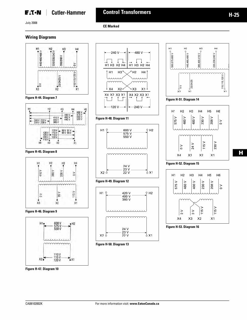
Wiring Diagrams
Figure H-44. Diagram 7
Figure H-45. Diagram 8
Figure H-46. Diagram 9
Figure H-47. Diagram 10
Figure H-48. Diagram 11
Figure H-49. Diagram 12
Figure H-50. Diagram 13
Figure H-51. Diagram 14
Figure H-52. Diagram 15
Figure H-53. Diagram 16
H1 H3 H2 H4 H1 H3 H2 H4
H1 H3 H2 H4
X4 X2 X3 X1
X4 X2 X3 X1 X4 X2 X3 X1
240 V 480 V
240 V120 V
H1 H2
X2 X1
600 V575 V550 V
24 V23 V22 V
H1 H2
X2 X1
420 V400 V380 V
24 V23 V22 V
H1 H2 H3 H4
X3 X2 X1
550,
575,
600
V
440,
460,
480
V
380,
400,
416
V
220,
230,
240
V
23/2
4/25
110,
115,
120
V
0V
0 V
X4 X3 X2 X1
H1 H2 H3 H4 H5 H6
575
V
460
V
400
V
230
V
208
V
0 V
0 V
24V
115
V
230
VX4 X3 X2 X1
H1 H2 H3 H4 H5 H657
5 V
460
V
400
V
230
V
208
V
0 V
0 V
0 V
115
V
115
V
Tab44.fm Page 25 Monday, September 22, 2008 9:04 PM
July 2008
H-26
For more information visit: www.EatonCanada.ca CA08102002K
Control Transformers
H
CE Marked
Product SelectionTable H-30. Type MTE CE Marked IP00
� See Pages H-24 and H-25 for Wiring Diagrams. Note: Transformers are designed to operate in a maximum ambient of 40°C. Note: Contact your local Eaton sales office for availability on additional CE Marked control transformers.
VA Dimensions (Inches) WeightLbs.
Dimensions (mm) Weightkg
WiringDiagram �
StyleNumber
Price
Height Width Depth Height Width Depth
Primary: 240 x 480, 230 x 460, 220 x 440 with JumpersSecondary: 120/115/110 50 75100150
33-1/43-1/24
33-3/83-3/44-1/2
3-3/83-3/83-3/83-3/4
3.5 4.8 5.9 8.5
76 83 89102
76 86 95114
86 86 86 95
1.6 2.2 2.7 3.9
1 1 1 1
CE0050E2ACECE0075E2ACECE0100E2ACECE0150E2ACE
200250300
444
4-1/24-1/24-1/2
3-3/444-3/8
10.611.313.2
102102102
114114114
95102111
4.8 5.1 6.0
1 1 1
CE0200E2ACECE0250E2ACECE0300E2ACE
350500750
4-1/24-1/24-1/2
5-1/45-1/45-1/4
4-7/85-1/87
14.921.029.8
114114114
133133133
124130178
6.8 9.513.5
1 1 1
CE0350E2ACECE0500E2ACECE0750E2ACE
Primary: 240 x 480 with JumpersSecondary: 24 50 75100150
33-1/43-1/24
33-3/83-3/44-1/2
3-3/83-3/83-3/84
3.4 4.2 5.9 8.5
76 83 89102
76 86 95114
86 86 86102
1.5 1.9 2.7 3.9
2 2 2 2
CE0050E2BCECE0075E2BCECE0100E2BCECE0150E2BCE
200250300
444
4-1/24-1/24-1/2
3-3/444-3/8
10.611.313.2
102102102
114114114
95102111
4.5 5.1 6.0
2 2 2
CE0200E2BCECE0250E2BCECE0300E2BCE
350500750
4-1/24-1/25
5-1/45-1/45-1/4
4-1/25-1/87
14.919.228.1
114114127
133133133
114130178
6.8 8.712.8
2 2 2
CE0350E2BCECE0500E2BCECE0750E2BCE
Primary: 120 x 240 with JumpersSecondary: 24 50 75100150
For other ratings or styles not shown, refer to Eaton. Discount Symbol . . . . . . . . . . . . . . . . . . . . . . . . . MC8
Tab44.fm Page 26 Monday, September 22, 2008 9:04 PM
July 2008
CA08102002K For more information visit: www.EatonCanada.ca
H-27Control Transformers
H
CE Marked
Table H-31. Type MTE CE Marked IP00
� See Pages H-24 and H-25 for Wiring Diagrams.Note: Transformers are designed to operate in a maximum ambient of 40°C. Note: Contact your local Eaton sales office for availability on additional CE Marked control transformers.
VA Dimensions (Inches) WeightLbs.
Dimensions (mm) Weightkg
WiringDiagram �
StyleNumber
Price
Height Width Depth Height Width Depth
Primary: 380/400/415Secondary: 110 x 220 with Jumpers 50 75100150
For other ratings or styles not shown, refer to Eaton. Discount Symbol . . . . . . . . . . . . . . . . . . . . . . . . . MC8
Tab44.fm Page 27 Monday, September 22, 2008 9:04 PM
July 2008
H-28
For more information visit: www.EatonCanada.ca CA08102002K
Control Transformers
H
CE Marked
Factory Mounted Finger-Safe Terminal Covers
Terminal Type A Terminal Type B Terminal Type C
Table H-32. Type MTK CE Marked with Factory Mounted Finger-Safe Terminal Covers IP20
� See Pages H-24 and H-25 for Wiring Diagrams.Note: For additional information, refer to the Cutler-Hammer Industrial Control Transformer Binder B1228A.Note: Contact your local Eaton sales office for availability on additional CE Marked control transformers.
VA Dimensions (Inches) WeightLbs.
Dimensions (mm) Weightkg
TerminalType
WiringDiagram �
StyleNumber
Price
Height Width Depth Height Width Depth
Primary: 240 x 480, 230 x 460, 220 x 440 with JumpersSecondary: 120/115/110 250 300 350 500
Tab44.fm Page 28 Monday, September 22, 2008 9:04 PM
July 2008
CA08102002K For more information visit: www.EatonCanada.ca
H-29Control Transformers
H
Industrial Control TransformersCE Marked
Table H-33. Type MTK CE Marked with Factory Mounted Finger-Safe Terminal Covers IP20
� See Pages H-24 and H-25 for Wiring Diagrams.� 24 volt secondary only available through 1000 VA.Note: For additional information, refer to the Cutler-Hammer Industrial Control Transformer Binder B1228A. Note: Contact your local Eaton sales office for availability on additional CE Marked control transformers.
Tab44.fm Page 29 Monday, September 22, 2008 9:04 PM
July 2008
H-30
For more information visit: www.EatonCanada.ca CA08102002K
Control Transformers
H
CE Marked
Table H-34. Acceptable Rating of Primary Overcurrent Protection for CE Marked Control Transformers
Table H-35. Acceptable Maximum Rating of Secondary Overcurrent Protection
Note: For values over 6.3A use 10 x 38 mm time-lag (IEC - 269-3-1). Ta = 40°C Control Type.
Fuses 10 x 38 mm (13/32” x 1-1/2”) Time-lag (IEC 269)
Sec. Voltage 50 75 100 150 200 250 300 350 500 750
115120200
2.02.01.0
2.02.02.0
4.04.02.0
4.04.04.0
6.06.04.0
6.06.04.0
8.08.04.0
10.010.0 6.0
12.012.0 8.0
20.020.012.0
208220230
1.01.01.0
2.01.01.0
2.02.02.0
4.04.04.0
4.04.04.0
4.04.04.0
4.04.04.0
6.0 6.0 6.0
8.0 6.0 6.0
12.010.010.0
240277380
1.0 .5 .5
1.01.01.0
2.01.01.0
4.02.02.0
4.04.02.0
4.04.04.0
4.04.04.0
4.0 4.0 4.0
6.0 6.0 6.0
10.0 8.0 6.0
400415440
.5 .5 .5
.5 .5 .5
1.01.01.0
2.01.01.0
2.02.02.0
4.04.02.0
4.04.04.0
4.0 4.0 4.0
4.0 4.0 4.0
6.0 6.0 6.0
460480550
.5 .5 .5
.5 .5 .5
1.0 .5 .5
1.01.01.0
2.02.01.0
2.02.02.0
4.04.02.0
4.0 4.0 4.0
4.0 4.0 4.0
6.0 6.0 4.0
575600
.5 .5
.5 .5
.5 .5
1.01.0
1.02.0
2.02.0
2.02.0
4.0 4.0
4.0 4.0
4.0 4.0
Miniature Fuses 5 x 20 mm Time-lag (IEC 127-2/III)
Sec. Voltage 50 75 100 150 200 250 300 350 500 750
23 24 25
2.502.502.50
4.004.004.00
5.005.005.00
8.008.008.00
10.010.010.0
12.0012.0012.00
16.0016.0016.00
16.0016.0016.00
25.0025.0025.00
—32.0032.00
90 95100
.63 .63 .50
1.00 .80 .80
1.251.251.00
2.001.601.60
2.50 2.50 2.00
3.15 3.15 2.50
4.00 4.00 3.15
4.00 4.00 4.00
6.30 6.30 5.00
10.00 8.00 8.00
110115120
.50 .50 .50
.80 .80 .63
1.001.001.00
1.601.601.25
2.00 2.00 2.00
2.50 2.50 2.50
3.15 3.15 2.50
4.00 3.15 3.15
5.00 5.00 5.00
8.00 8.00 6.30
220230240
.25 .25 .25
.40 .40 .315
.50 .50 .50
.80 .80 .63
1.00 1.00 1.00
1.25 1.25 1.25
1.60 1.60 1.25
1.60 1.60 1.60
2.50 2.50 2.50
4.00 4.00 3.15
Tab44.fm Page 30 Monday, September 22, 2008 9:04 PM
July 2008
CA08102002K For more information visit: www.EatonCanada.ca
H-31Control Transformers
H
Power SupplyIntelligent Technologies (IT.)
Product DescriptionThe Cutler-Hammer® Intelligent Tech-nologies (IT.) line of Power Supplies from Eaton’s electrical business is designed to work in a variety of appli-cations. These include as the power supply to the IT. line of power control products. They also work in most Con-trol applications which require 24V DC. All of the IT. power supplies are designed to provide the highest out-rush current in the industry for units of their size. It is also the only line to pro-vide 110 – 480V AC input voltage down to the smallest current units.
Application DescriptionThe IT. line of Power Supplies is specifi-cally designed to work with the S801, S811, MV801 and IT. electro-mechanical devices. They can also serve in a variety of other applications including support of sensors, operator interfaces, PLCs, communication networks, heaters and lights and in many other industrial applications where 24V DC power supplies are required. With the widest operating temperature range in the industry, rugged design and a long list of advanced features, they are able to be applied in a very wide range of applications.
The higher input voltage ranges are designed to allow users to eliminate the need for a control power trans-former in the enclosure or cabinet, thus saving space, wiring and money.
Features■ Wide range voltage input (110 –
600V AC operating)■ High current outrush capability in
all units■ Semiconductor F47 approved■ Long ride-through capability
designed in■ Wide operating temperature range■ Power Supplies can be used in
parallel (6.5A and greater)■ Multiple 24V DC terminals for easy
wiring■ DIN rail and panel mount available
in most units■ Removable terminal connections■ IP20 fingerproof design■ Larger units have —
❑ Active power factor correction❑ Adjustable output voltages❑ Fault contacts❑ Analogue outputs
Benefits■ 24V DC control enhances personnel
and equipment safety.■ IP20 design improves personnel
safety.■ Removable terminal connectors
make installation and repair quick and easy.
■ Wide operating temperature range allows for installation in most areas where standard control products can be installed today.
■ High current outrush capability allows use of smaller power sup-plies in many applications and ensures stable output during high power demand cycles.
■ Due to long ride-through time, the Power Supply can maintain the con-trol power system during brown out and black out conditions.
Standards and Certifications■ UL Listed 508■ CSA Certified■ CE Marked■ F47 Certified
IT. Power Supplies
Tab44.fm Page 31 Monday, September 22, 2008 9:04 PM
July 2008
H-32
For more information visit: www.EatonCanada.ca CA08102002K
TS35 Rail or Chassis; Leave 4 in. (10 cm) free space on venting sides. TS35 Rail (with optional PSSDIN Kit) or Chassis; Leave 4 in. (10 cm) free space on venting sides.
—
Environmental PerformanceStorage Temperature
-25 to 80°C -25 to 80°C -25 to 80C -25 to 80C -40 to 85°C -40 to 85°C -40 to 85°C -40 to 85°C
Operating Temperature
-5 to 50°C -5 to 50°C -5 to 50°C -5 to 50°C -25 to 50°C -25 to 50°C -25 to 50°C -25 to 50°C
Storage Humidity
5 to 95% 5 to 95% 5 to 95% 5 to 95% 5 to 95% 5 to 95% 5 to 95% 5 to 95%