22
SRAMAluminum Road Wheel & Hub Service ManualS30 AL Gold / Race / Sprint S27 AL Comp
2
© Copyright SRAM LLC 2010This document includes trademarks and registered trademarks of SRAM LLC designated by the symbols ™ and ® respectively.
For exploded diagram and part number information, please refer to the Spare Parts Catalog available on our website at www.sram.com.
For order information, please contact your local SRAM distributor or dealer.
Information contained in this document is subject to change at any time without prior notice.
Your product's appearance may differ from the pictures/diagrams contained in this document.
Product names used in this document may be trademarks or registered trademarks of others.
GEN.0000000003216
SRAM LLC WARRAntyExtEnt of LiMitEd WARRAntySRAM warrants its products to be free from defects in materials or workmanship for a period of two years after original purchase. This warranty only applies to the original owner and is not transferable. Claims under this warranty must be made through the retailer where the bicycle or the SRAM component was purchased. Original proof of purchase is required.
LoCAL LAWThis warranty statement gives the customer specific legal rights. The customer may also have other rights which vary from state to state (USA), from province to province (Canada), and from country to country elsewhere in the world.
To the extent that this warranty statement is inconsistent with the local law, this warranty shall be deemed modified to be consistent with such law, under such local law, certain disclaimers and limitations of this warranty statement may apply to the customer. For example, some states in the United States of America, as well as some governments outside of the United States (including provinces in Canada) may:
Preclude the disclaimers and limitations of this warranty statement from limiting the a. statutory rights of the consumer (e.g. United Kingdom).Otherwise restrict the ability of a manufacturer to enforce such disclaimers or limita-b. tions.
LiMitAtionS of LiAbiLityTo the extent allowed by local law, except for the obligations specifically set forth in this warranty statement, in no event shall SRAM or its third party supplies be liable for direct, indirect, special, incidental, or consequential damages.
LiMitAtionS of WARRAntyThis warranty does not apply to products that have been incorrectly installed and/or adjusted according to the respective SRAM technical installation manual. The SRAM installation manuals can be found online at www.sram.com, www.rockshox.com, www.avidbike.com, www.truvativ.com, or www.zipp.com.
This warranty does not apply to damage to the product caused by a crash, impact, abuse of the product, non-compliance with manufacturers specifications of usage or any other circumstances in which the product has been subjected to forces or loads beyond its design.
This warranty does not apply when the product has been modified.
This warranty does not apply when the serial number or production code has been deliberately altered, defaced or removed.
This warranty does not apply to normal wear and tear. Wear and tear parts are subject to damage as a result of normal use, failure to service according to SRAM recommendations and/or riding or installation in conditions or applications other than recommended.
Wear and tear parts are identified as:
This warranty shall not cover damages caused by the use of parts of different manufacturers.
This warranty shall not cover damages caused by the use of parts that are not compatible, suitable and/or authorised by SRAM for use with SRAM components.
This warranty shall not cover damages resulting from commercial (rental) use.
All SRAM wheels (carbon and AL) have a 100 kg (220 lbs) rider weight limit.
Dust seals•Bushings•Air sealing o-rings•Glide rings•Rubber moving parts•Foam rings•Rear shock mounting •hardware and main sealsUpper tubes (stanchions)•Stripped threads/bolts •(aluminium, titanium, magnesium or steel)
Brake sleeves•Brake pads•Chains•Sprockets•Cassettes•Shifter and brake cables •(inner and outer)Handlebar grips•Shifter grips•Jockey wheels•Disc brake rotors•Wheel braking surfaces•
Bottomout pads•Bearings•Bearing races•Pawls•Transmission gears•Spokes•Free hubs•Aero bar pads•Corrosion•Tools•
3
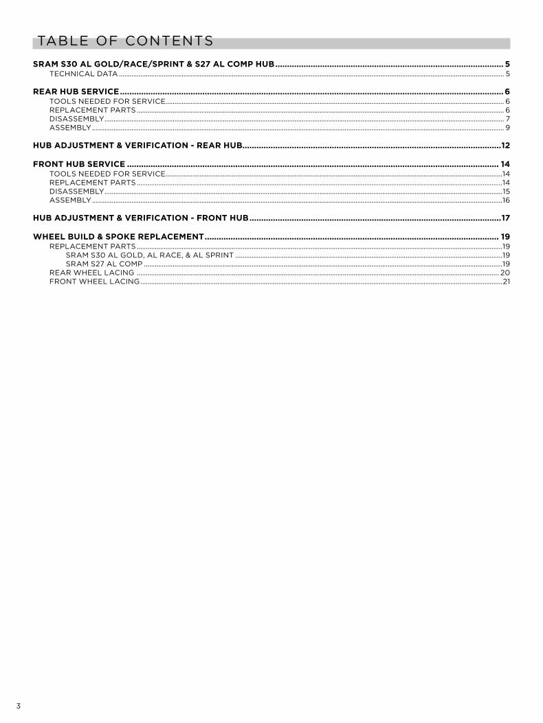
TABLE OF CONTENTS
SRAM S30 AL goLd/RACE/SPRint & S27 AL CoMP HUb ................................................................................................. 5TECHNICAL DATA ....................................................................................................................................................................................................................... 5
REAR HUb SERviCE ...................................................................................................................................................................6TOOLS NEEDED FOR SERvICE ............................................................................................................................................................................................. 6REPLACEMENT PARTS ............................................................................................................................................................................................................. 6DISASSEMBLY ............................................................................................................................................................................................................................... 7ASSEMBLY ...................................................................................................................................................................................................................................... 9
HUb AdjUStMEnt & vERifiCAtion - REAR HUb..............................................................................................................12
fRont HUb SERviCE .............................................................................................................................................................. 14TOOLS NEEDED FOR SERvICE ............................................................................................................................................................................................14REPLACEMENT PARTS ............................................................................................................................................................................................................14DISASSEMBLY ..............................................................................................................................................................................................................................15ASSEMBLY .....................................................................................................................................................................................................................................16
HUb AdjUStMEnt & vERifiCAtion - fRont HUb ...........................................................................................................17
WHEEL bUiLd & SPokE REPLACEMEnt ............................................................................................................................. 19REPLACEMENT PARTS ............................................................................................................................................................................................................19
SRAM S30 AL GOLD, AL RACE, & AL SPRINT .....................................................................................................................................................19SRAM S27 AL COMP ........................................................................................................................................................................................................19
REAR WHEEL LACING .......................................................................................................................................................................................................... 20FRONT WHEEL LACING ..........................................................................................................................................................................................................21

4
SAFETY FIRST!We care about YOU. Please, always wear your safety glasses and
protective gloves when servicing your wheels.Protect yourself! Wear your safety gear!
5
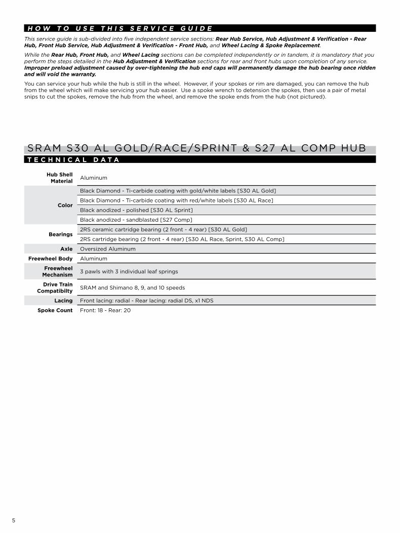
H o W t o U S E t H i S S E R v i C E g U i d EThis service guide is sub-divided into five independent service sections: Rear Hub Service, Hub Adjustment & Verification - Rear Hub, Front Hub Service, Hub Adjustment & Verification - Front Hub, and Wheel Lacing & Spoke Replacement.
While the Rear Hub, Front Hub, and Wheel Lacing sections can be completed independently or in tandem, it is mandatory that you perform the steps detailed in the Hub Adjustment & Verification sections for rear and front hubs upon completion of any service. Improper preload adjustment caused by over-tightening the hub end caps will permanently damage the hub bearing once ridden and will void the warranty.
You can service your hub while the hub is still in the wheel. However, if your spokes or rim are damaged, you can remove the hub from the wheel which will make servicing your hub easier. Use a spoke wrench to detension the spokes, then use a pair of metal snips to cut the spokes, remove the hub from the wheel, and remove the spoke ends from the hub (not pictured).
SRAM S30 AL GOLD/RACE/SPRINT & S27 AL COMP HUBt E C H n i C A L d A t A
Hub Shell Material Aluminum
Color
Black Diamond - Ti-carbide coating with gold/white labels [S30 AL Gold]
Black Diamond - Ti-carbide coating with red/white labels [S30 AL Race]
Black anodized - polished [S30 AL Sprint]
Black anodized - sandblasted [S27 Comp]
bearings2RS ceramic cartridge bearing (2 front - 4 rear) [S30 AL Gold]
2RS cartridge bearing (2 front - 4 rear) [S30 AL Race, Sprint, S30 AL Comp]
Axle Oversized Aluminum
freewheel body Aluminum
freewheel Mechanism 3 pawls with 3 individual leaf springs
drive train Compatibilty SRAM and Shimano 8, 9, and 10 speeds
Lacing Front lacing: radial - Rear lacing: radial DS, x1 NDS
Spoke Count Front: 18 - Rear: 20
6
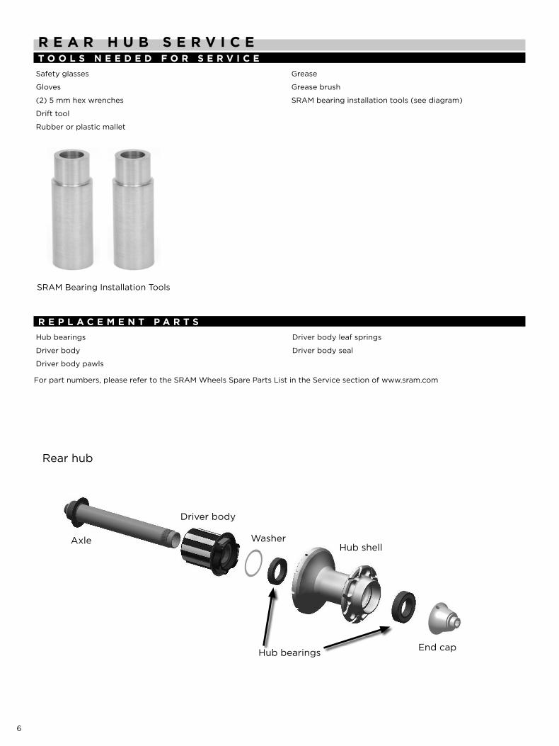
R E A R H U b S E R v i C Et o o L S n E E d E d f o R S E R v i C ESafety glasses
Gloves
(2) 5 mm hex wrenches
Drift tool
Rubber or plastic mallet
Grease
Grease brush
SRAM bearing installation tools (see diagram)
R E P L A C E M E n t P A R t SHub bearings
Driver body
Driver body pawls
Driver body leaf springs
Driver body seal
For part numbers, please refer to the SRAM Wheels Spare Parts List in the Service section of www.sram.com
Rear hub
Hub shellAxle
Driver body
Washer
Hub bearings
SRAM Bearing Installation Tools
End cap
7
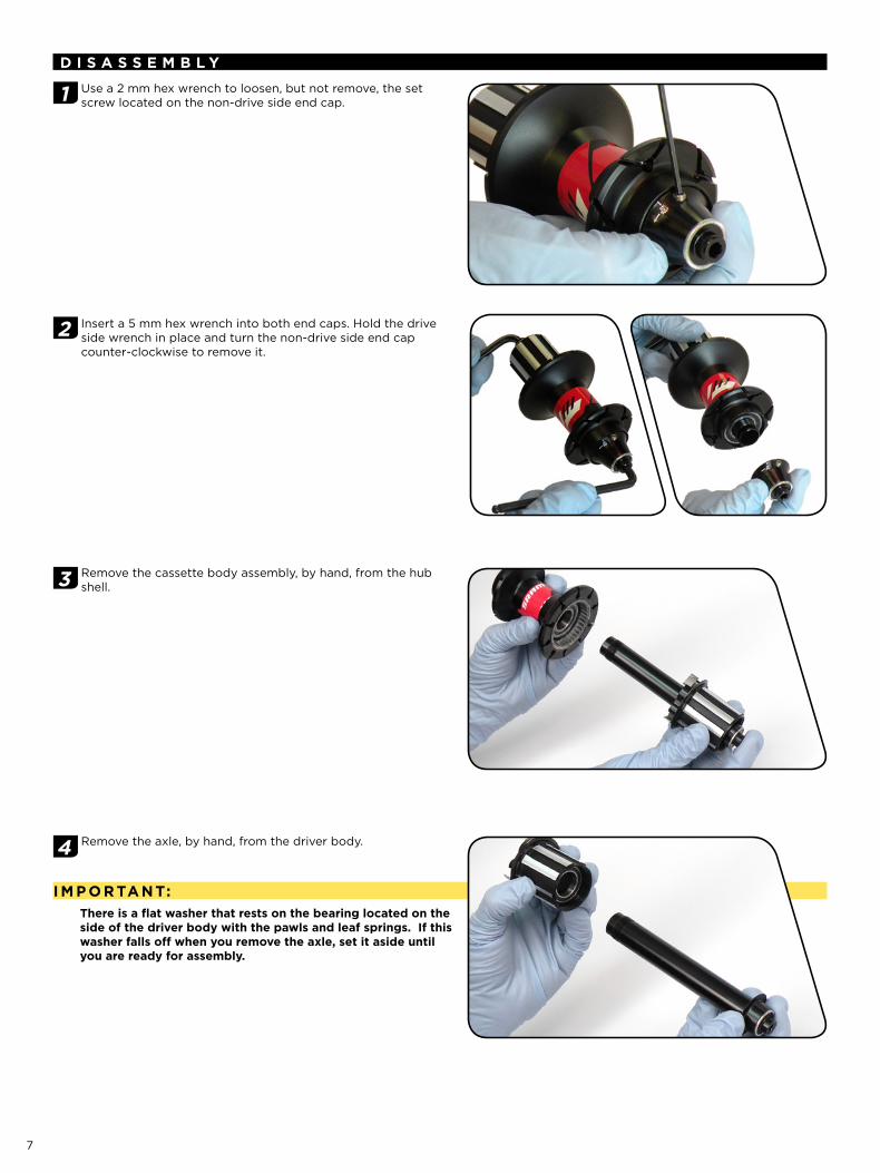
d i S A S S E M b L y
1 Use a 2 mm hex wrench to loosen, but not remove, the set screw located on the non-drive side end cap.
2 Insert a 5 mm hex wrench into both end caps. Hold the drive side wrench in place and turn the non-drive side end cap counter-clockwise to remove it.
3 Remove the cassette body assembly, by hand, from the hub shell.
4 Remove the axle, by hand, from the driver body.
i M P o R tA n t:there is a flat washer that rests on the bearing located on the side of the driver body with the pawls and leaf springs. if this washer falls off when you remove the axle, set it aside until you are ready for assembly.
8
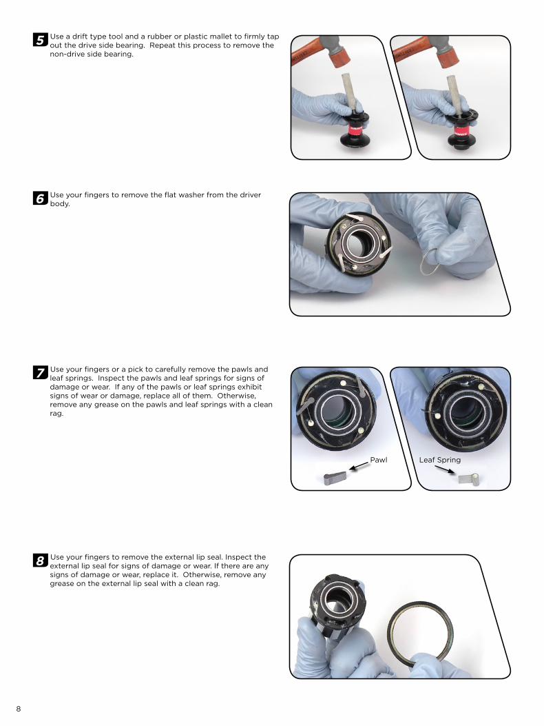
5 Use a drift type tool and a rubber or plastic mallet to firmly tap out the drive side bearing. Repeat this process to remove the non-drive side bearing.
6 Use your fingers to remove the flat washer from the driver body.
7 Use your fingers or a pick to carefully remove the pawls and leaf springs. Inspect the pawls and leaf springs for signs of damage or wear. If any of the pawls or leaf springs exhibit signs of wear or damage, replace all of them. Otherwise, remove any grease on the pawls and leaf springs with a clean rag.
8 Use your fingers to remove the external lip seal. Inspect the external lip seal for signs of damage or wear. If there are any signs of damage or wear, replace it. Otherwise, remove any grease on the external lip seal with a clean rag.
Pawl Leaf Spring
9
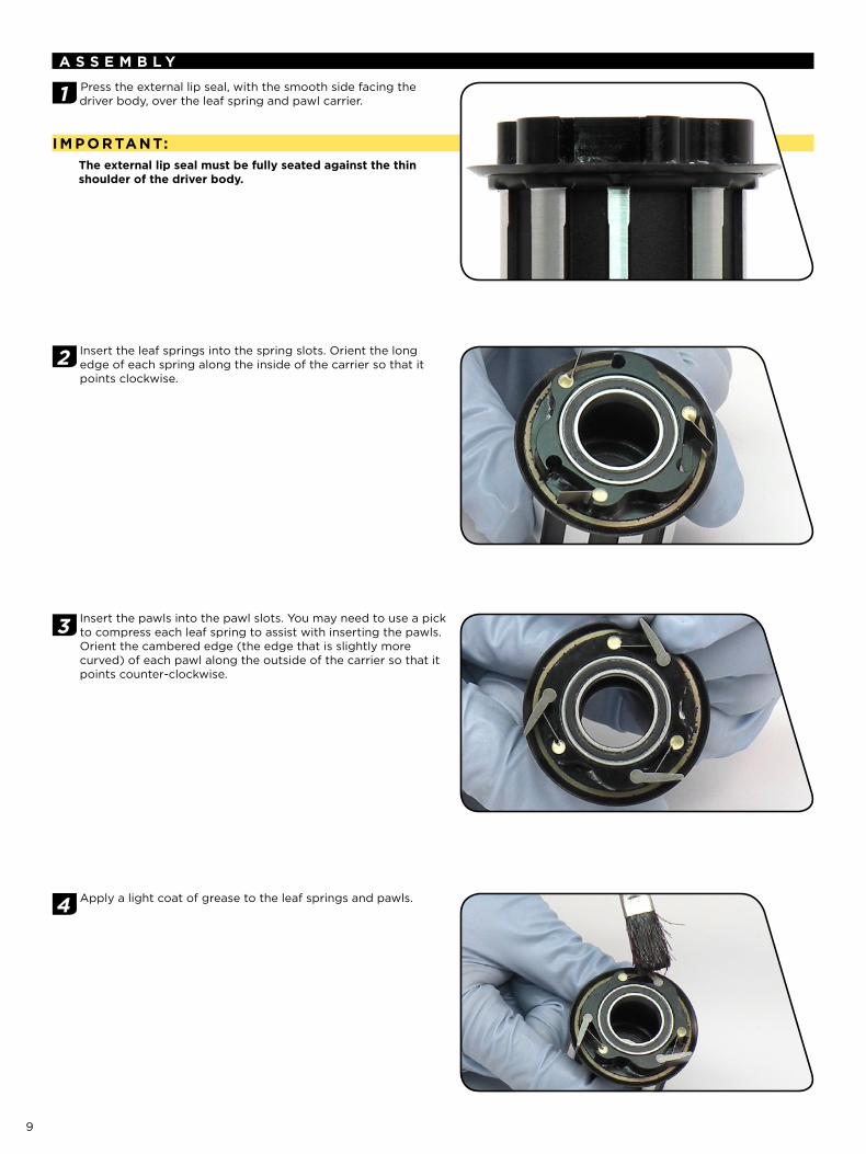
A S S E M b L y
1 Press the external lip seal, with the smooth side facing the driver body, over the leaf spring and pawl carrier.
i M P o R tA n t:the external lip seal must be fully seated against the thin shoulder of the driver body.
2 Insert the leaf springs into the spring slots. Orient the long edge of each spring along the inside of the carrier so that it points clockwise.
3 Insert the pawls into the pawl slots. You may need to use a pick to compress each leaf spring to assist with inserting the pawls. Orient the cambered edge (the edge that is slightly more curved) of each pawl along the outside of the carrier so that it points counter-clockwise.
4 Apply a light coat of grease to the leaf springs and pawls.
10
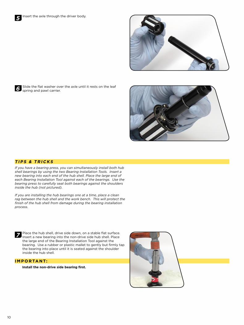
5 Insert the axle through the driver body.
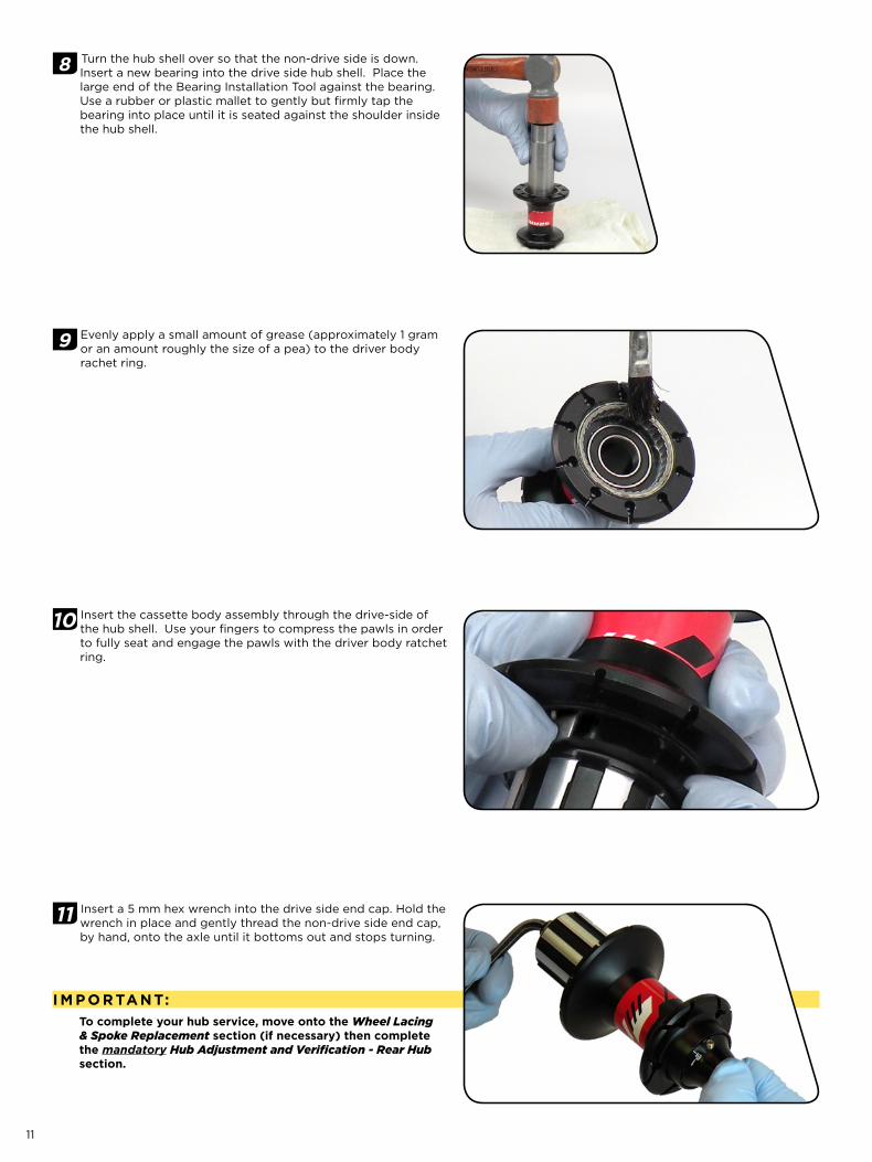
6 Slide the flat washer over the axle until it rests on the leaf spring and pawl carrier.
t i P S & t R i C k SIf you have a bearing press, you can simultaneously install both hub shell bearings by using the two Bearing Installation Tools. Insert a new bearing into each end of the hub shell. Place the large end of each Bearing Installation Tool against each of the bearings. Use the bearing press to carefully seat both bearings against the shoulders inside the hub (not pictured).
If you are installing the hub bearings one at a time, place a clean rag between the hub shell and the work bench. This will protect the finish of the hub shell from damage during the bearing installation process.
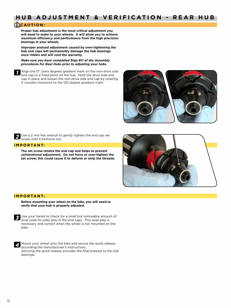
7 Place the hub shell, drive side down, on a stable flat surface. Insert a new bearing into the non-drive side hub shell. Place the large end of the Bearing Installation Tool against the bearing. Use a rubber or plastic mallet to gently but firmly tap the bearing into place until it is seated against the shoulder inside the hub shell.
i M P o R tA n t:install the non-drive side bearing first.
11
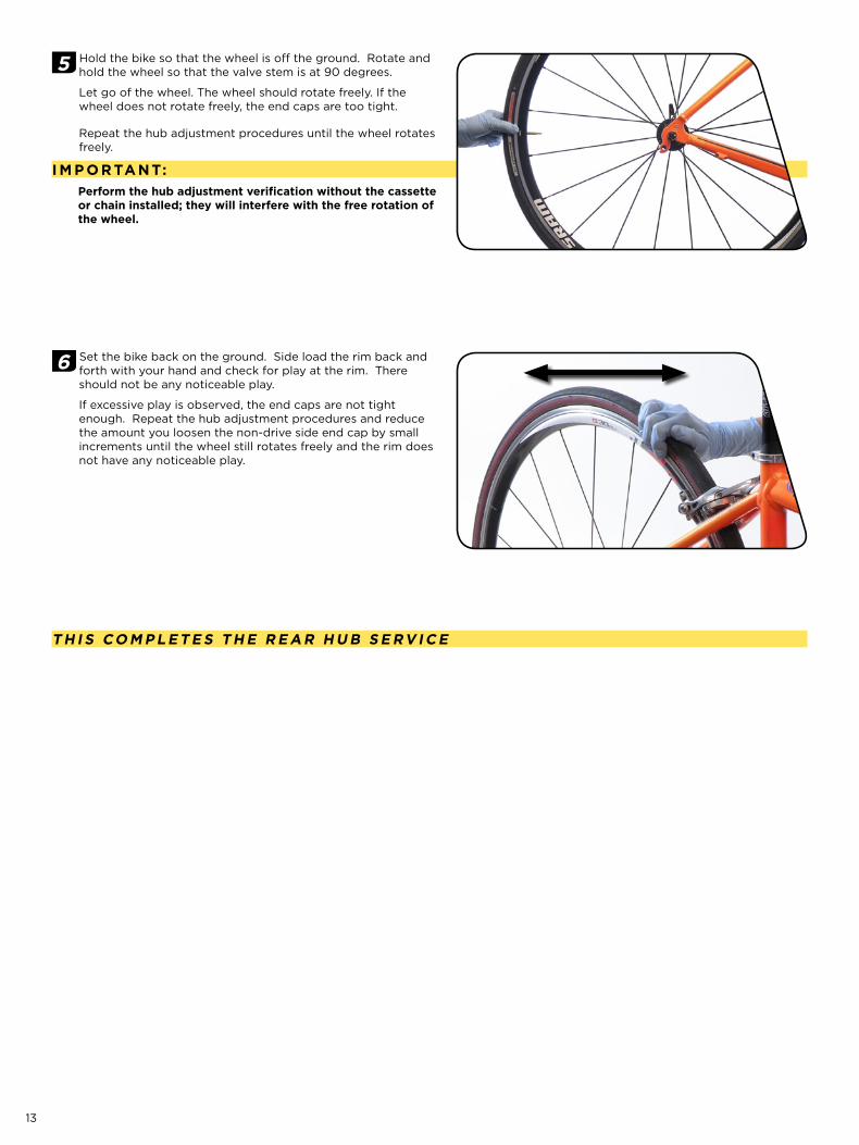
8 Turn the hub shell over so that the non-drive side is down. Insert a new bearing into the drive side hub shell. Place the large end of the Bearing Installation Tool against the bearing. Use a rubber or plastic mallet to gently but firmly tap the bearing into place until it is seated against the shoulder inside the hub shell.
9 Evenly apply a small amount of grease (approximately 1 gram or an amount roughly the size of a pea) to the driver body rachet ring.
10 Insert the cassette body assembly through the drive-side of the hub shell. Use your fingers to compress the pawls in order to fully seat and engage the pawls with the driver body ratchet ring.
11 Insert a 5 mm hex wrench into the drive side end cap. Hold the wrench in place and gently thread the non-drive side end cap, by hand, onto the axle until it bottoms out and stops turning.
i M P o R tA n t:to complete your hub service, move onto the Wheel Lacing & Spoke Replacement section (if necessary) then complete the mandatory Hub Adjustment and Verification - Rear Hub section.
12
H U b A d j U S t M E n t & v E R i f i C At i o n - R E A R H U bC AU ti o n :Proper hub adjustment is the most critical adjustment you will need to make to your wheels. it will allow you to achieve maximum efficiency and performance from the high precision bearings in your wheels.
improper preload adjustment caused by over-tightening the hub end caps will permanently damage the hub bearings once ridden and will void the warranty.
Make sure you have completed Step #11 of the Assembly procedures for Rear Hubs prior to adjusting your hubs.
1 Align the 0° (zero degree) gradient mark on the non-drive side end cap to a fixed point on the hub. Hold the drive side end cap in place and loosen the non-drive side end cap by rotating it counter-clockwise to the 120 degree gradient mark.
2 Use a 2 mm hex wrench to gently tighten the end cap set screw until it bottoms out.
i M P o R tA n t:the set screw retains the end cap and helps to prevent unintentional adjustment. do not force or over-tighten the set screw; this could cause it to deform or strip the threads.
i M P o R tA n t:before mounting your wheel on the bike, you will need to verify that your hub is properly adjusted.
3 Use your hands to check for a small but noticeable amount of axial (side-to-side) play in the end caps. This axial play is necessary and correct when the wheel is not mounted on the bike.
4 Mount your wheel onto the bike and secure the quick release according the manufacturer’s instructions.Securing the quick release provides the final preload to the hub bearings.
13
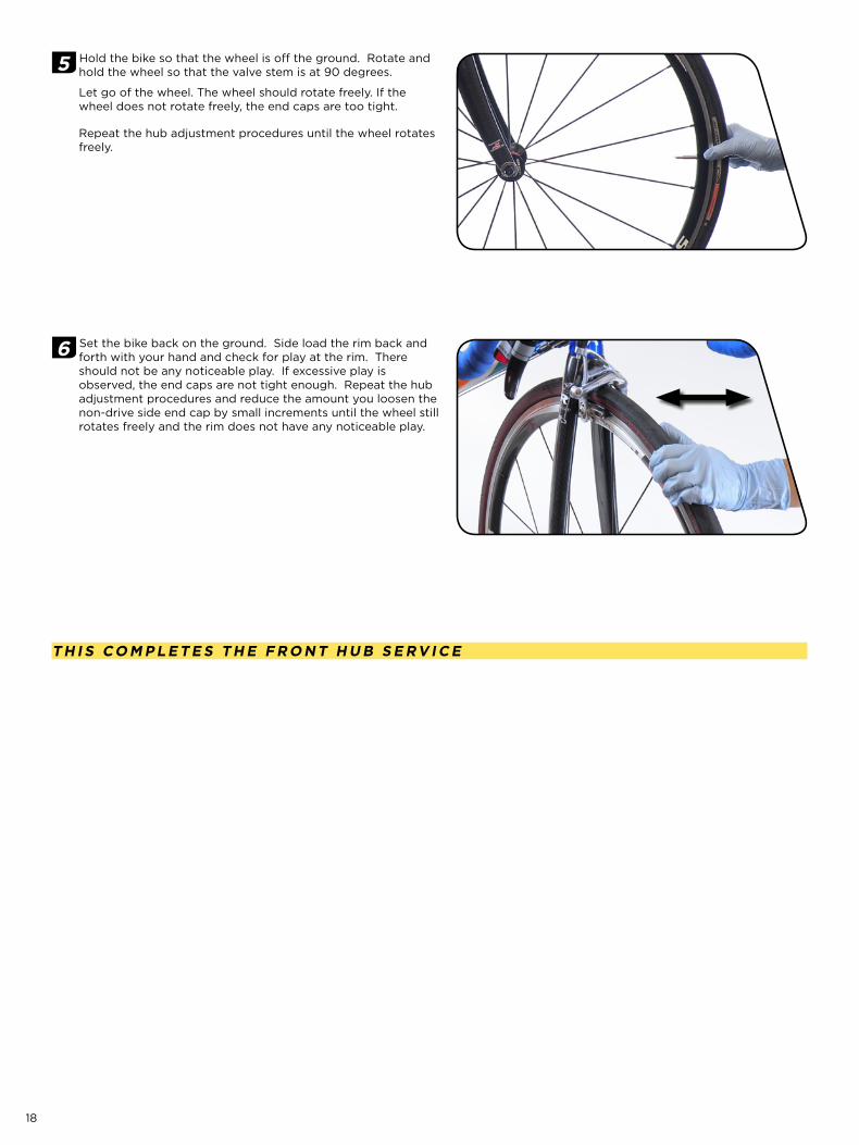
5 Hold the bike so that the wheel is off the ground. Rotate and hold the wheel so that the valve stem is at 90 degrees.
Let go of the wheel. The wheel should rotate freely. If the wheel does not rotate freely, the end caps are too tight.
Repeat the hub adjustment procedures until the wheel rotates freely.
i M P o R tA n t:Perform the hub adjustment verification without the cassette or chain installed; they will interfere with the free rotation of the wheel.
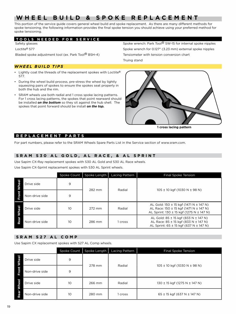
6 Set the bike back on the ground. Side load the rim back and forth with your hand and check for play at the rim. There should not be any noticeable play.
If excessive play is observed, the end caps are not tight enough. Repeat the hub adjustment procedures and reduce the amount you loosen the non-drive side end cap by small increments until the wheel still rotates freely and the rim does not have any noticeable play.
t H i S Co M P L E t E S t H E R E A R H U b S E Rv i C E
14
f R o n t H U b S E R v i C Et o o L S n E E d E d f o R S E R v i C ESafety glasses
Gloves
(2) 5 mm hex wrenches
Drift tool
Rubber or plastic mallet
Grease
Grease brush
SRAM bearing installation tools (see diagram)
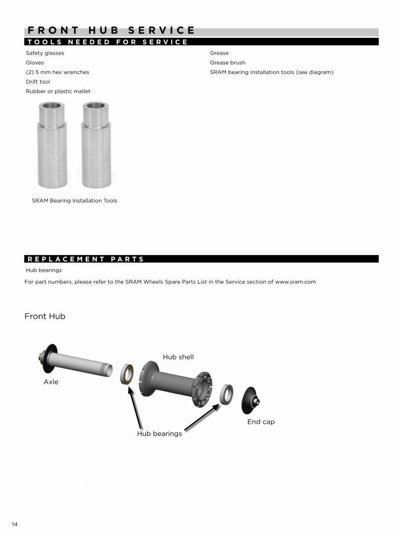
R E P L A C E M E n t P A R t SHub bearings
For part numbers, please refer to the SRAM Wheels Spare Parts List in the Service section of www.sram.com
Front Hub
End cap
Hub bearings
Hub shell
Axle
SRAM Bearing Installation Tools
15
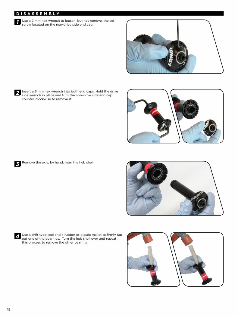
d i S A S S E M b L y
1 Use a 2 mm hex wrench to loosen, but not remove, the set screw located on the non-drive side end cap.
2 Insert a 5 mm hex wrench into both end caps. Hold the drive side wrench in place and turn the non-drive side end cap counter-clockwise to remove it.
3 Remove the axle, by hand, from the hub shell.
4 Use a drift type tool and a rubber or plastic mallet to firmly tap out one of the bearings. Turn the hub shell over and repeat this process to remove the other bearing.
16
A S S E M b L y
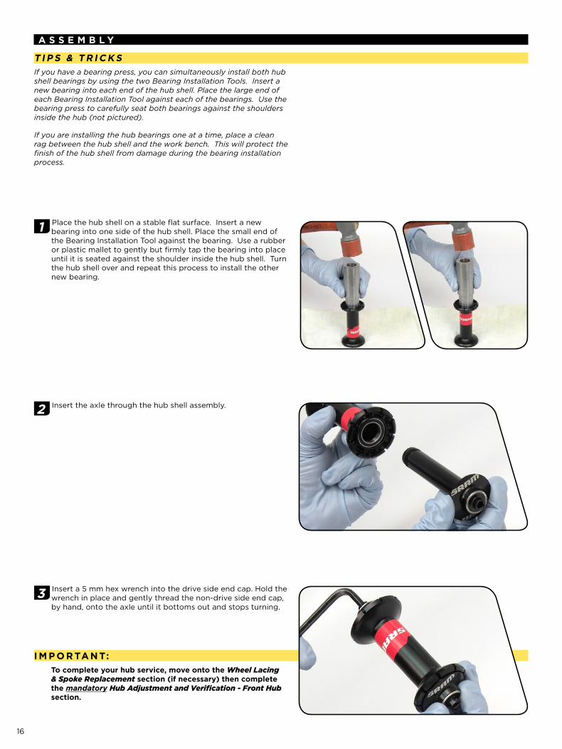
ti P S & t R i C k SIf you have a bearing press, you can simultaneously install both hub shell bearings by using the two Bearing Installation Tools. Insert a new bearing into each end of the hub shell. Place the large end of each Bearing Installation Tool against each of the bearings. Use the bearing press to carefully seat both bearings against the shoulders inside the hub (not pictured).
If you are installing the hub bearings one at a time, place a clean rag between the hub shell and the work bench. This will protect the finish of the hub shell from damage during the bearing installation process.
1 Place the hub shell on a stable flat surface. Insert a new bearing into one side of the hub shell. Place the small end of the Bearing Installation Tool against the bearing. Use a rubber or plastic mallet to gently but firmly tap the bearing into place until it is seated against the shoulder inside the hub shell. Turn the hub shell over and repeat this process to install the other new bearing.
2 Insert the axle through the hub shell assembly.
3 Insert a 5 mm hex wrench into the drive side end cap. Hold the wrench in place and gently thread the non-drive side end cap, by hand, onto the axle until it bottoms out and stops turning.
i M P o R tA n t:to complete your hub service, move onto the Wheel Lacing & Spoke Replacement section (if necessary) then complete the mandatory Hub Adjustment and Verification - Front Hub section.
17
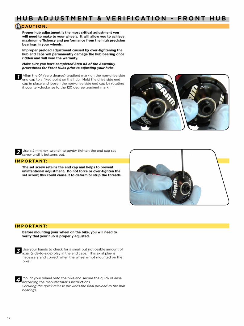
H U b A d j U S t M E n t & v E R i f i C At i o n - f R o n t H U bC AU ti o n :Proper hub adjustment is the most critical adjustment you will need to make to your wheels. it will allow you to achieve maximum efficiency and performance from the high precision bearings in your wheels.
improper preload adjustment caused by over-tightening the hub end caps will permanently damage the hub bearing once ridden and will void the warranty.
Make sure you have completed Step #3 of the Assembly procedures for Front Hubs prior to adjusting your hubs.
1 Align the 0° (zero degree) gradient mark on the non-drive side end cap to a fixed point on the hub. Hold the drive side end cap in place and loosen the non-drive side end cap by rotating it counter-clockwise to the 120 degree gradient mark.
2 Use a 2 mm hex wrench to gently tighten the end cap set screw until it bottoms out.
i M P o R tA n t:the set screw retains the end cap and helps to prevent unintentional adjustment. do not force or over-tighten the set screw; this could cause it to deform or strip the threads.
i M P o R tA n t:before mounting your wheel on the bike, you will need to verify that your hub is properly adjusted.
3 Use your hands to check for a small but noticeable amount of axial (side-to-side) play in the end caps. This axial play is necessary and correct when the wheel is not mounted on the bike.
4 Mount your wheel onto the bike and secure the quick release according the manufacturer’s instructions.Securing the quick release provides the final preload to the hub bearings.
18
5 Hold the bike so that the wheel is off the ground. Rotate and hold the wheel so that the valve stem is at 90 degrees.
Let go of the wheel. The wheel should rotate freely. If the wheel does not rotate freely, the end caps are too tight.
Repeat the hub adjustment procedures until the wheel rotates freely.
6 Set the bike back on the ground. Side load the rim back and forth with your hand and check for play at the rim. There should not be any noticeable play. If excessive play is observed, the end caps are not tight enough. Repeat the hub adjustment procedures and reduce the amount you loosen the non-drive side end cap by small increments until the wheel still rotates freely and the rim does not have any noticeable play.
t H i S Co M P L E t E S t H E f R o n t H U b S E Rv i C E
19
W H E E L b U i L d & S P o k E R E P L A C E M E n tThis portion of the service guide covers general wheel build and spoke replacement. As there are many different methods for spoke tensioning, the following information provides the final spoke tension you should achieve using your preferred method for spoke tensioning.
t o o L S n E E d E d f o R S E R v i C ESafety glasses
Loctite® 577
Bladed spoke adjustment tool (ex. Park Tool® BSH-4)
Spoke wrench: Park Tool® SW-15 for internal spoke nipples
Spoke wrench for 0.127" (3.23 mm) external spoke nipples
Tensiometer with tension conversion chart
Truing stand
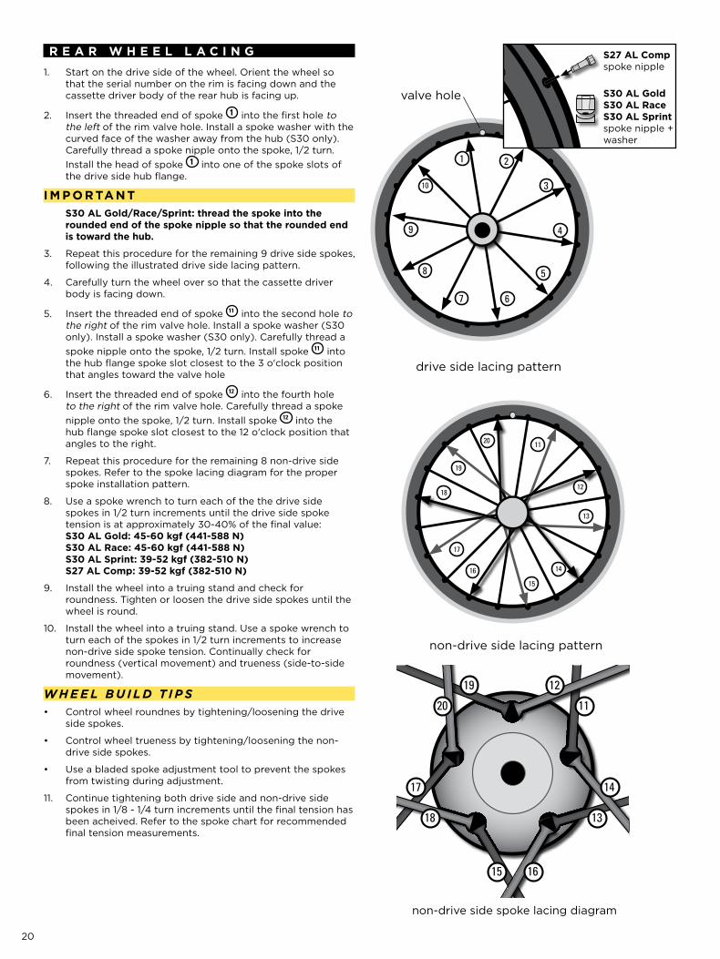
W H e e L b u I Ld t I p S
1 cross lacing pattern
• Lightly coat the threads of the replacement spokes with Loctite® 577.
During the wheel build process, pre-stress the wheel by lightly •squeezing pairs of spokes to ensure the spokes seat properly in both the hub and the rim.
SRAM wheels use both radial and 1 cross spoke lacing patterns. •For 1 cross lacing patterns, the spokes that point rearward should be installed on the bottom so they sit against the hub shell. The spokes that point forward should be install on the top.
R E P L A C E M E n t P A R t S
For part numbers, please refer to the SRAM Wheels Spare Parts List in the Service section of www.sram.com.
S R A M S 3 0 A L g o L d , A L R A C E , & A L S P R i n tUse Sapim CX-Ray replacement spokes with S30 AL Gold and S30 AL Race wheels.
Use Sapim CX-Sprint replacement spokes with S30 AL Sprint wheels.
Spoke Count Spoke Length Lacing Pattern Final Spoke Tension
fro
nt W
heel
Drive side 9
282 mm Radial 105 ± 10 kgf (1030 N ± 98 N)
Non-drive side 9
Rea
r W
heel Drive side 10 272 mm Radial
AL Gold: 150 ± 15 kgf (1471 N ± 147 N) AL Race: 150 ± 15 kgf (1471 N ± 147 N)
AL Sprint: 130 ± 15 kgf (1275 N ± 147 N)
Non-drive side 10 286 mm 1 crossAL Gold: 85 ± 15 kgf (833 N ± 147 N) AL Race: 85 ± 15 kgf (833 N ± 147 N) AL Sprint: 65 ± 15 kgf (637 N ± 147 N)
S R A M S 2 7 A L C o M PUse Sapim CX replacement spokes with S27 AL Comp wheels.
Spoke Count Spoke Length Lacing Pattern Final Spoke Tension
fro
nt W
heel
Drive side 9
278 mm Radial 105 ± 10 kgf (1030 N ± 98 N)
Non-drive side 9
Rea
r W
heel
Drive side 10 266 mm Radial 130 ± 15 kgf (1275 N ± 147 N)
Non-drive side 10 280 mm 1 cross 65 ± 15 kgf (637 N ± 147 N)
20
R E A R W H E E L L A C i n g
Start on the drive side of the wheel. Orient the wheel so 1. that the serial number on the rim is facing down and the cassette driver body of the rear hub is facing up.
Insert the threaded end of spoke 2. 1 into the first hole to the left of the rim valve hole. Install a spoke washer with the curved face of the washer away from the hub (S30 only). Carefully thread a spoke nipple onto the spoke, 1/2 turn. Install the head of spoke 1 into one of the spoke slots of the drive side hub flange.
i M P o R tA n tS30 AL gold/Race/Sprint: thread the spoke into the rounded end of the spoke nipple so that the rounded end is toward the hub.
Repeat this procedure for the remaining 9 drive side spokes, 3. following the illustrated drive side lacing pattern.
Carefully turn the wheel over so that the cassette driver 4. body is facing down.
Insert the threaded end of spoke 5. 11 into the second hole to the right of the rim valve hole. Install a spoke washer (S30 only). Install a spoke washer (S30 only). Carefully thread a spoke nipple onto the spoke, 1/2 turn. Install spoke 11 into the hub flange spoke slot closest to the 3 o'clock position that angles toward the valve hole
Insert the threaded end of spoke 6. 12 into the fourth hole to the right of the rim valve hole. Carefully thread a spoke nipple onto the spoke, 1/2 turn. Install spoke 12 into the hub flange spoke slot closest to the 12 o'clock position that angles to the right.
Repeat this procedure for the remaining 8 non-drive side 7. spokes. Refer to the spoke lacing diagram for the proper spoke installation pattern.
Use a spoke wrench to turn each of the the drive side 8. spokes in 1/2 turn increments until the drive side spoke tension is at approximately 30-40% of the final value: S30 AL gold: 45-60 kgf (441-588 n) S30 AL Race: 45-60 kgf (441-588 n) S30 AL Sprint: 39-52 kgf (382-510 n) S27 AL Comp: 39-52 kgf (382-510 n)
Install the wheel into a truing stand and check for 9. roundness. Tighten or loosen the drive side spokes until the wheel is round.
Install the wheel into a truing stand. Use a spoke wrench to 10. turn each of the spokes in 1/2 turn increments to increase non-drive side spoke tension. Continually check for roundness (vertical movement) and trueness (side-to-side movement).
W H e e L b u I Ld t I p SControl wheel roundnes by tightening/loosening the drive •side spokes.
Control wheel trueness by tightening/loosening the non-•drive side spokes.
Use a bladed spoke adjustment tool to prevent the spokes •from twisting during adjustment.
Continue tightening both drive side and non-drive side 11. spokes in 1/8 - 1/4 turn increments until the final tension has been acheived. Refer to the spoke chart for recommended final tension measurements.
valve hole
drive side lacing pattern
2
3
4
5
67
8
9
10
1
S27 AL Comp spoke nipple
S30 AL gold S30 AL Race S30 AL Sprint spoke nipple + washer
non-drive side lacing pattern
20 11
12
13
14
15
16
17
18
19
non-drive side spoke lacing diagram
20 11
12
13
14
15 16
17
18
19
21
valve hole
2
3
4
56
7
8
9
1
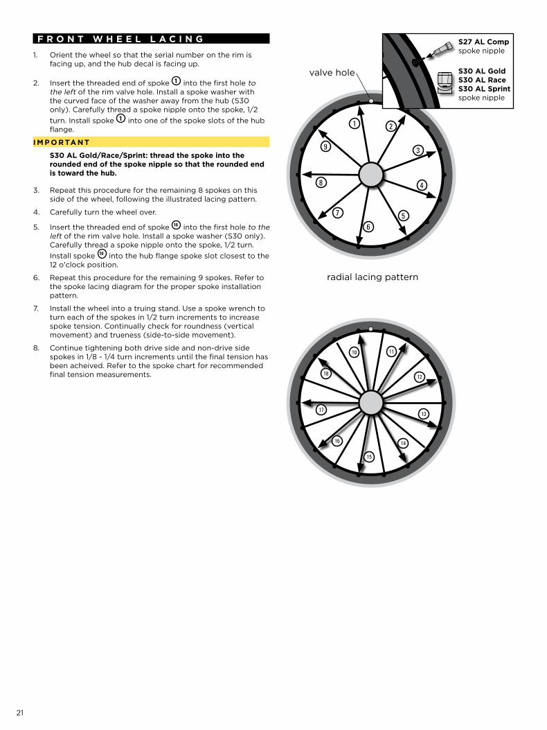
f R o n t W H E E L L A C i n g
Orient the wheel so that the serial number on the rim is 1. facing up, and the hub decal is facing up.
Insert the threaded end of spoke 2. 1 into the first hole to the left of the rim valve hole. Install a spoke washer with the curved face of the washer away from the hub (S30 only). Carefully thread a spoke nipple onto the spoke, 1/2 turn. Install spoke 1 into one of the spoke slots of the hub flange.
i M P o R tA n t
S30 AL gold/Race/Sprint: thread the spoke into the rounded end of the spoke nipple so that the rounded end is toward the hub.
Repeat this procedure for the remaining 8 spokes on this 3. side of the wheel, following the illustrated lacing pattern.
Carefully turn the wheel over.4.
Insert the threaded end of spoke 5. 10 into the first hole to the left of the rim valve hole. Install a spoke washer (S30 only). Carefully thread a spoke nipple onto the spoke, 1/2 turn. Install spoke 10 into the hub flange spoke slot closest to the 12 o'clock position.
Repeat this procedure for the remaining 9 spokes. Refer to 6. the spoke lacing diagram for the proper spoke installation pattern.
Install the wheel into a truing stand. Use a spoke wrench to 7. turn each of the spokes in 1/2 turn increments to increase spoke tension. Continually check for roundness (vertical movement) and trueness (side-to-side movement).
Continue tightening both drive side and non-drive side 8. spokes in 1/8 - 1/4 turn increments until the final tension has been acheived. Refer to the spoke chart for recommended final tension measurements.
S27 AL Comp spoke nipple
S30 AL gold S30 AL Race S30 AL Sprint spoke nipple
10 11
12
13
14
15
16
17
18
radial lacing pattern

[www.sram.com]
GEN.0000000003216


![Untitled-1 [] · 2002. 9. 20. · LODED DIAGRAMS 27 Alphabetical Index By Supplement 2- 3- S27: S27: S27: S27: 12- 1 12- 2 14- 4 14- 14 -3 O And 027 Gauqeg Locomotives Diesel Engines](https://static.documents.pub/doc/80x56/602e2319c329b50ba6732f93/untitled-1-2002-9-20-loded-diagrams-27-alphabetical-index-by-supplement.jpg)


