35
Service & Support Answers for industry. Cover Technical Instructions for Configuring an S7 Connection S7-300 / S7-400 Industrial Ethernet CPs FAQ January 2011

Service & Support
Answers for industry.
Cover
Technical Instructions for Configuring an S7 Connection
S7-300 / S7-400 Industrial Ethernet CPs
FAQ January 2011

Question
2 Technical instructions on configuring an S7 connection
V1.0, Item ID: 17628518
This entry is from the Service&Support portal of Siemens AG, Sector Industry, Industry Automation and Drive Technologies. The general terms of use (http://www.siemens.com/terms_of_use) apply.
Clicking the link below directly displays the download page of this document.
http://support.automation.siemens.com/WW/view/en/17628518
Question How do you configure a specified and an unspecified S7 connection for data exchange between S7-300 and / or S7-400 over Industrial Ethernet CPs?
Answer The instructions and notes listed in this document provide a detailed answer to this question.

Table of Contents
Technical instructions on configuring an S7 connection V1.0, Item ID: 17628518 3
Table of Contents 1 Introduction........................................................................................................ 4 2 Configuration ..................................................................................................... 5
2.1 Configuring CP343-1 and CP443-1 Advanced .................................... 5 2.1.1 Assigning IP addresses to CP343-1 and CP443-1 Advanced............. 5 2.1.2 Entering the IP address of CP343-1 in the Hardware Configuration
and downloading the configuration into the CPU................................. 8 2.1.3 Entering the IP address of CP443-1 Advanced in the Hardware
Configuration and downloading the configuration into the CPU ........ 10 2.2 Configuring the S7 Connection Bilaterally.......................................... 13 2.2.1 Configuring a specified S7 connection............................................... 14 2.2.2 Configuring an unspecified S7 connection......................................... 19
Configuring an unspecified S7 connection for the S7-300................. 19 Configuring an unspecified S7 connection for the S7-400................. 22
2.3 Configuring the S7 Connection Unilaterally ....................................... 27 2.3.1 Configuring an S7 connection unilaterally for the S7-300.................. 27 2.3.2 Configuring an S7 connection unilaterally for the S7-400.................. 31

1 Introduction
4 Technical instructions on configuring an S7 connection
V1.0, Item ID: 17628518
1 Introduction You can use the S7 communication through S7 connections for data exchange by way of the Industrial Ethernet CPs of S7-300 and S7-400.
In this example an S7-300 is connected over the PROFINET interface of the CP343-1 on the subnetwork 172.16.0.0. The S7-400 on the other hand is connected over the GBIT interface of the CP443-1 Advanced on the subnetwork 172.16.0.0. The PROFINET interface of the CP443-1 Advanced is connected on the subnetwork 192.168.99.0.
Configuration overview
Figure 1-1 shows an overview of the configuration.
Figure 1-1
S7-400S7-300
CP
343-1
CP
443-1 Ad
van
ced
S7 connection
SCALALANCE X
IP address: 172.16.43.2subnet mask: 255.255.0.0
IP address PROFINET interface:192.168.99.121subnet mask: 255.255.255.0IP address Gigabit interface:172.16.49.99subnet mask: 255.255.0.0

2 Configuration
Technical instructions on configuring an S7 connection V1.0, Item ID: 17628518 5
2 Configuration Below we describe how to configure an S7 connection for bilateral exchange of data by way of the Industrial Ethernet CPs of S7-300 and S7-400.
The S7 connection is configured bilaterally in the S7-300 and in the S7-400.
2.1 Configuring CP343-1 and CP443-1 Advanced
2.1.1 Assigning IP addresses to CP343-1 and CP443-1 Advanced
The following IP addresses are used in this configuration.
Table 2-1
Industrial Ethernet CP Interface IP address Subnet mask
CP343-1 PROFINET 172.16.43.2 255.255.0.0
CP443-1 Advanced PROFINET 192.168.99.121 255.255.255.0
CP443-1 Advanced GBIT 172.16.49.99 255.255.0.0
Assign the IP addresses to CP343-1 and CP443-1 Advanced.
Follow the instructions below for assigning the IP addresses.

2 Configuration
6 Technical instructions on configuring an S7 connection
V1.0, Item ID: 17628518
Table 2-2
No. Configuration step Note
1. Connect the SIMATIC Field PG on which the configuration created with STEP 7 is stored to the PROFINET interface of CP343-1.
In Windows network settings LAN (Local Area Network) of the SIMATIC Field PG you enter an IP address that is in the same subnetwork as that of CP343-1. In this example the IP address 172.16.43.100 and subnetwork mask 255.255.0.0 are used for the SIMATIC Field PG.
2. In the SIMATIC Manager you open the STEP 7 project that contains the configurations of S7-300 and S7-400 between which the data is to be exchanged over an S7 connection.
By means of the menu PLC Edit Ethernet Node you open the "Edit Ethernet Node" dialog.

2 Configuration
Technical instructions on configuring an S7 connection V1.0, Item ID: 17628518 7
No. Configuration step Note
3. In the "Edit Ethernet Node" dialog you click the "Browse..." button and select the MAC address of CP343-1.
4. Enter the IP address and subnet mask of CP343-1. Click the "Assign IP Configuration" button to assign the IP address entered to CP343-1. Then click the "Close" button to close the "Edit Ethernet Node" dialog.
5. Enter the assigned IP address in the Hardware Configuration of the S7-300 station and download the configuration into the S7-300 CPU.
See section 2.1.2

2 Configuration
8 Technical instructions on configuring an S7 connection
V1.0, Item ID: 17628518
No. Configuration step Note
6. Connect the SIMATIC Field PG on which the configuration created with STEP 7 is stored to the PROFINET interface of CP443-1 Advanced.
In Windows network settings LAN (Local Area Network) of the SIMATIC Field PG you enter an IP address that is in the same subnetwork as that of CP443-1. In this example the IP address 192.168.99.100 and subnetwork mask 255.255.255.0 are used for the SIMATIC Field PG.
7. Repeat configuration steps 2 to 4 to assign the IP address 192.168.99.121 and subnet mask 255.255.255.0 to CP443-1 Advanced.
8. Enter the assigned IP address in the Hardware Configuration of the S7-400 station and download the configuration into the S7-400 CPU.
See section 2.1.3
2.1.2 Entering the IP address of CP343-1 in the Hardware Configuration and downloading the configuration into the CPU
After you have assigned the IP address 172.16.43.2 and subnet mask 255.255.0.0 to CP343-1 you enter the assigned IP address in the Hardware Configuration.

2 Configuration
Technical instructions on configuring an S7 connection V1.0, Item ID: 17628518 9
Table 2-3
No. Configuration step Note
1. In the SIMATIC Manager you mark the SIMATIC S7 300 station and double-click "Hardware" in order to open the Hardware Configuration of the S7-300 station.
2. In the Hardware Configuration of S7-300 you double-click the PROFINET interface of CP343-1. The Properties dialog of the PROFINET interface opens.
3. In the Properties dialog of the PROFINET interface you click the "Properties..." button to open the "Properties - Ethernet interface PN-IO" dialog.

2 Configuration
10 Technical instructions on configuring an S7 connection
V1.0, Item ID: 17628518
No. Configuration step Note
4. Enter the IP address 172.16.43.2 and the subnet mask 255.255.0.0. Activate the "Set MAC address / Use ISO protocol" function and enter the MAC address 00-0E-8C-D9-F0-1D of CP343-1. Assign an existing subnet to CP343-1 or click the "New..." button to create a new subnet. Apply the settings with "OK".
5. Save and compile the hardware configuration of the S7-300 and then load the configuration into the S7-300 CPU.
Save and Compiledownload
2.1.3 Entering the IP address of CP443-1 Advanced in the Hardware Configuration and downloading the configuration into the CPU
After you have assigned the IP address 192.168.99.121 and subnet mask 255.255.255.0 to CP343-1 you enter the assigned IP address in the Hardware Configuration.

2 Configuration
Technical instructions on configuring an S7 connection V1.0, Item ID: 17628518 11
Table 2-4
No. Configuration step Note
1. In the SIMATIC Manager you mark the SIMATIC S7 400 station and double-click "Hardware" in order to open the Hardware Configuration of the S7-400 station.
2. In the Hardware Configuration of S7-400 you double-click the PROFINET interface of CP443-1 Advanced. The Properties dialog of the PROFINET interface opens.
3. In the Properties dialog of the PROFINET interface you click the "Properties..." button to open the "Properties - Ethernet interface PN-IO" dialog.
2 Configuration
12 Technical instructions on configuring an S7 connection
V1.0, Item ID: 17628518
No. Configuration step Note
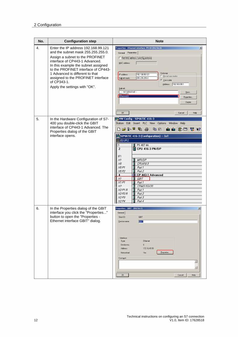
4. Enter the IP address 192.168.99.121 and the subnet mask 255.255.255.0. Assign a subnet to the PROFINET interface of CP443-1 Advanced. In this example the subnet assigned to the PROFINET interface of CP443-1 Advanced is different to that assigned to the PROFINET interface of CP343-1. Apply the settings with "OK".
5. In the Hardware Configuration of S7-400 you double-click the GBIT interface of CP443-1 Advanced. The Properties dialog of the GBIT interface opens.
6. In the Properties dialog of the GBIT interface you click the "Properties..." button to open the "Properties - Ethernet interface GBIT" dialog.

2 Configuration
Technical instructions on configuring an S7 connection V1.0, Item ID: 17628518 13
No. Configuration step Note
7. Activate the "Set MAC address / Use ISO protocol" function and enter the MAC address 00-0E-8C-DB-D2-98 of CP443-1 Advanced. Enter the IP address 172.16.49.99 and the subnet mask 255.255.0.0. Assign the same subnet to the GBIT interface of CP443-1 Advanced as to the PROFINET interface of CP343-1. Apply the settings with "OK".
8. Save and compile the hardware configuration of the S7-400 and then load the configuration into the S7-400 CPU.
Save and compile download
2.2 Configuring the S7 Connection Bilaterally
Once you have completed configuration of CP343-1 and CP443-1 Advanced and have downloaded the hardware configuration into the S7-300 CPU and the S7-400 CPU, then you configure the S7 connection for data exchange between S7-300 and S7-400 by way of Industrial Ethernet CPs.
The function blocks and system functions below are used for data exchange by way of S7 connections configured bilaterally in S7-300 and S7-400.
FB/SFB12 "BSEND" and FB/SFB13 "BRCV"
FB/SFB8 "USEND" and FB9 "URCV"
FB/SFB14 "GET" and FB/SFB15 "PUT"
2 Configuration
14 Technical instructions on configuring an S7 connection
V1.0, Item ID: 17628518
Note If you use the BSEND and BRCV or USEND and URCV services for data transfer, you must configure the S7 connection bilaterally for S7-300 and S7-400, because the services are based on the client-client principle.
You can use the PUT and GET services for data transfer by way of S7 connections configured unilaterally as well as by way of S7 connections configured bilaterally. They are based on the client-server principle.
Below we describe how to configure a specified and an unspecified S7 connection for S7-300 and S7-400.
2.2.1 Configuring a specified S7 connection
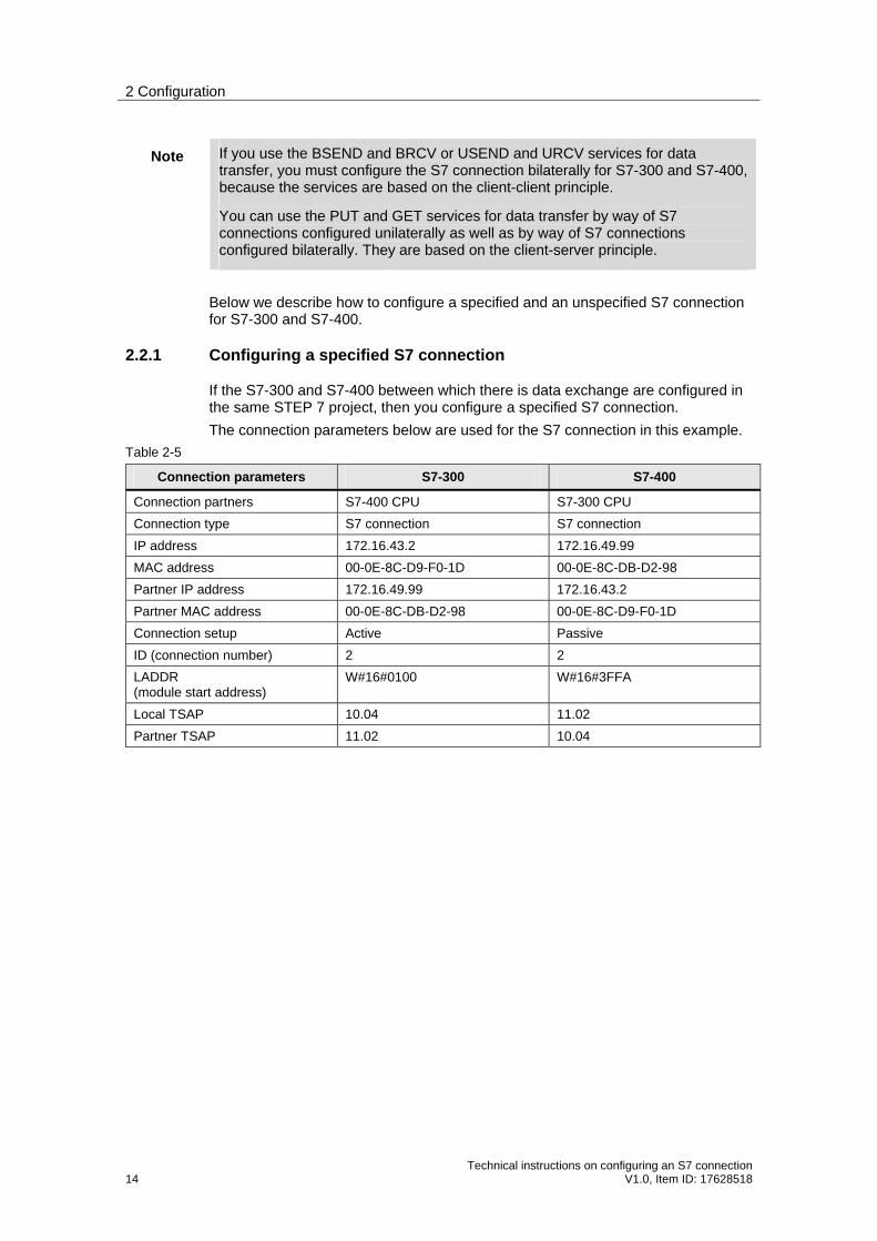
If the S7-300 and S7-400 between which there is data exchange are configured in the same STEP 7 project, then you configure a specified S7 connection.
The connection parameters below are used for the S7 connection in this example.
Table 2-5
Connection parameters S7-300 S7-400
Connection partners S7-400 CPU S7-300 CPU
Connection type S7 connection S7 connection
IP address 172.16.43.2 172.16.49.99
MAC address 00-0E-8C-D9-F0-1D 00-0E-8C-DB-D2-98
Partner IP address 172.16.49.99 172.16.43.2
Partner MAC address 00-0E-8C-DB-D2-98 00-0E-8C-D9-F0-1D
Connection setup Active Passive
ID (connection number) 2 2
LADDR (module start address)
W#16#0100 W#16#3FFA
Local TSAP 10.04 11.02
Partner TSAP 11.02 10.04

2 Configuration
Technical instructions on configuring an S7 connection V1.0, Item ID: 17628518 15
Follow the instructions below to configure a specified S7 connection.
Table 2-6
No. Configuration step Note
1. In the SIMATIC Manager you open the STEP 7 project that contains the configurations of S7-300 and/or S7-400 between which the data is to be exchanged over an S7 connection.
By means of the menu Options Configure Network you open NetPro where you configure the S7 connection.
2. Mark the CPU of the SIMATIC 300 station and create a new connection by means of the menu Insert New Connection….

2 Configuration
16 Technical instructions on configuring an S7 connection
V1.0, Item ID: 17628518
No. Configuration step Note
3. You configure the connection partner and the type of connection in the "Insert New Connection" dialog. Select the S7-400 CPU as connection partner. Select "S7 connection" as the connection type. Then click the "Apply" button to open the Properties dialog of the S7 connection.
4. In the Properties dialog of the S7 connection "General" tab you determine the connection number by means of the block parameter "ID". You specify the connection number at the "ID" input parameter of the function blocks or system functions used for sending and receiving the data. The function blocks and system functions are called in the user program of the CPU. Activate the function "Active connection establishment" because the S7-300 actively establishes the S7 connection.
2 Configuration
Technical instructions on configuring an S7 connection V1.0, Item ID: 17628518 17
No. Configuration step Note
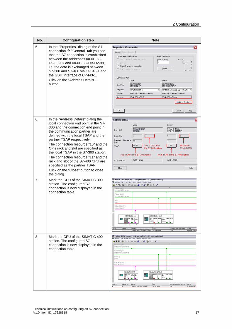
5. In the "Properties" dialog of the S7 connection "General" tab you see that the S7 connection is established between the addresses 00-0E-8C-D9-F0-1D and 00-0E-8C-DB-D2-98, i.e. the data is exchanged between S7-300 and S7-400 via CP343-1 and the GBIT interface of CP443-1. Click on the "Address Details..." button.
6. In the "Address Details" dialog the local connection end point in the S7-300 and the connection end point in the communication partner are defined with the local TSAP and the partner TSAP respectively. The connection resource "10" and the CP's rack and slot are specified as the local TSAP in the S7-300 station. The connection resource "11" and the rack and slot of the S7-400 CPU are specified as the partner TSAP. Click on the "Close" button to close the dialog.
Slot of the CP in the S7-300 station
Slot of theS7-400 CPU
local TSAP in the S7-300 station local TSAP in the S7-400 station
7. Mark the CPU of the SIMATIC 300 station. The configured S7 connection is now displayed in the connection table.
8. Mark the CPU of the SIMATIC 400 station. The configured S7 connection is now displayed in the connection table.

2 Configuration
18 Technical instructions on configuring an S7 connection
V1.0, Item ID: 17628518
No. Configuration step Note
9. Once you have completed the connection configuration, you save and compile the configuration. Mark the SIMATIC 300 station and download the configuration into the S7-300 CPU. Then mark the SIMATIC 400 station and download the configuration into the S7-400 CPU.
Save and compile download
10. Call the function blocks below in the user program of the S7-300.
FB12 "BSEND" and FB13 "BRCV" or
FB8 "USEND" and FB9 "URCV" or
FB14 "GET" and FB15 "PUT"
You will find function blocks in the library "SIMATIC_NET_CP CP CP 300 Blocks". At the link below is a sample program for the S7-300 with the call of the function blocks FB12 "BSEND" and FB13 "BRCV". http://support.automation.siemens.com/WW/view/de/18516182 At the link below is a sample program for the S7-300 with the call of the function blocks FB8 "BSEND" and FB9 "BRCV". http://support.automation.siemens.com/WW/view/de/22791526 At the link below is a sample program for the S7-300 with the call of the function blocks FB14 "GET" and FB15 "PUT". http://support.automation.siemens.com/WW/view/de/18610307
11. Call the system functions below in the user program of the S7-400.
SFB12 "BSEND" and SFB13 "BRCV" or
SFB8 "USEND" and SFB9 "URCV" or
SFB14 "GET" and SFB15 "PUT"
These system functions are available in the library "Standard Library System Function Blocks Blocks". At the link below is a sample program for the S7-400 with the call of the system functions SFB14 "GET" and SFB15 "PUT". http://support.automation.siemens.com/WW/view/de/1819293

2 Configuration
Technical instructions on configuring an S7 connection V1.0, Item ID: 17628518 19
2.2.2 Configuring an unspecified S7 connection
If the S7-300 and S7-400 between which there is data exchange are configured in different STEP 7 projects, then you configure an unspecified S7 connection.
The connection parameters below are used for the S7 connection in this example.
Table 2-7
Connection parameters S7-300 S7-400
Connection partners Unspecified Unspecified
Connection type S7 connection S7 connection
IP address 172.16.43.2 172.16.49.99
MAC address 00-0E-8C-D9-F0-1D 00-0E-8C-DB-D2-98
Partner IP address 172.16.49.99 172.16.43.2
Partner MAC address 00-0E-8C-DB-D2-98 00-0E-8C-D9-F0-1D
Connection setup Active Passive
ID (connection number) 3 3
LADDR (module start address)
W#16#0100 W#16#3FFA
Local TSAP 11.04 12.02
Partner TSAP 12.02 11.04
Note The configurations of the connection parameters for the S7-300 and the S7-400 must match.
Configuring an unspecified S7 connection for the S7-300
Follow the instructions below to configure an unspecified S7 connection for the S7-300.
Table 2-8
No. Configuration step Note
1. In the SIMATIC Manager you open the STEP 7 project that contains the configuration of S7-300 which is to send and receive the data over an S7 connection.
By means of the menu Options Configure Network you open NetPro where you configure the S7 connection.

2 Configuration
20 Technical instructions on configuring an S7 connection
V1.0, Item ID: 17628518
No. Configuration step Note
2. Mark the CPU of the SIMATIC 300 station and create a new connection by means of the menu Insert New Connection….
3. In the "Insert New Connection" dialog you select the item "unspecified" as connection partner. Select "S7 connection" as the connection type. Then click the "Apply" button to open the Properties dialog of the S7 connection.

2 Configuration
Technical instructions on configuring an S7 connection V1.0, Item ID: 17628518 21
No. Configuration step Note
4. In the Properties dialog of the S7 connection "General" tab you determine the connection number by means of the block parameter "ID". You specify the connection number at the "ID" input parameter of the function blocks used for sending and receiving the data. The function blocks are called in the user program of the CPU. Activate the function "Active connection establishment" because the S7-300 actively establishes the S7 connection.
5. In the Properties dialog of the S7 connection "General" tab you enter the IP address of the communication partner, i.e. in this example you enter the IP address 172.16.49.99 of CP443-1 Advanced. Click on the "Address Details..." button.
6. In the "Address Details" dialog the local connection end point in the S7-300 and the connection end point in the communication partner are defined with the local TSAP and the partner TSAP respectively. The connection resource "11" and the CP's rack and slot are specified as the local TSAP in the S7-300 station. For the partner you enter the rack and slot of the S7-400 CPU and select the connection resource for the partner so that the local TSAP of the S7-400 is defined as the partner TSAP. Apply the settings with "OK".
Slot of the CPU
local TSAP in the S7-300 station local TSAP in the S7-400 station
2 Configuration
22 Technical instructions on configuring an S7 connection
V1.0, Item ID: 17628518
No. Configuration step Note
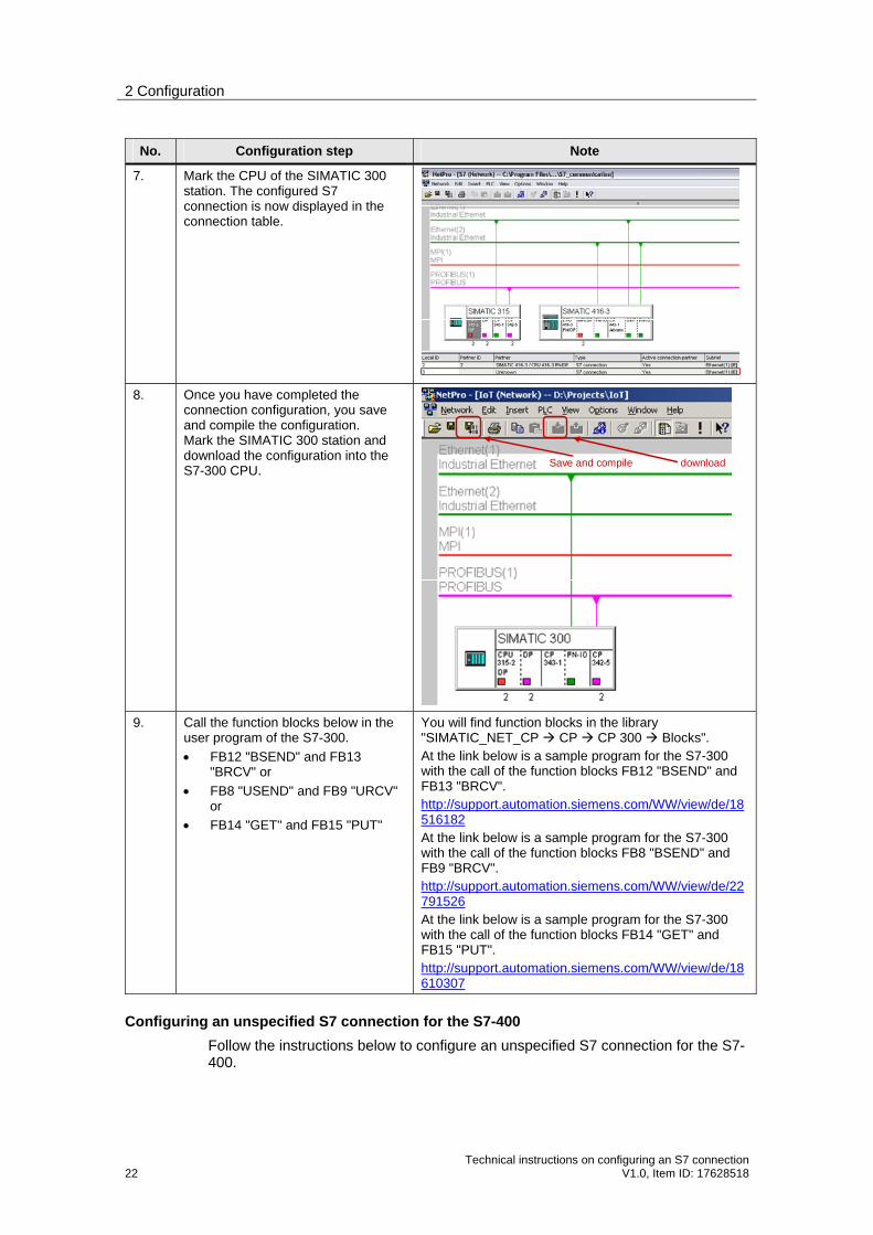
7. Mark the CPU of the SIMATIC 300 station. The configured S7 connection is now displayed in the connection table.
8. Once you have completed the connection configuration, you save and compile the configuration. Mark the SIMATIC 300 station and download the configuration into the S7-300 CPU.
Save and compile download
9. Call the function blocks below in the user program of the S7-300.
FB12 "BSEND" and FB13 "BRCV" or
FB8 "USEND" and FB9 "URCV" or
FB14 "GET" and FB15 "PUT"
You will find function blocks in the library "SIMATIC_NET_CP CP CP 300 Blocks". At the link below is a sample program for the S7-300 with the call of the function blocks FB12 "BSEND" and FB13 "BRCV". http://support.automation.siemens.com/WW/view/de/18516182 At the link below is a sample program for the S7-300 with the call of the function blocks FB8 "BSEND" and FB9 "BRCV". http://support.automation.siemens.com/WW/view/de/22791526 At the link below is a sample program for the S7-300 with the call of the function blocks FB14 "GET" and FB15 "PUT". http://support.automation.siemens.com/WW/view/de/18610307
Configuring an unspecified S7 connection for the S7-400
Follow the instructions below to configure an unspecified S7 connection for the S7-400.

2 Configuration
Technical instructions on configuring an S7 connection V1.0, Item ID: 17628518 23
Table 2-9
No. Configuration step Note
1. In the SIMATIC Manager you open the STEP 7 project that contains the configuration of S7-400 which is to send and receive the data over an S7 connection.
By means of the menu Options Configure Network you open NetPro where you configure the S7 connection.
2. Mark the CPU of the SIMATIC 400 station and create a new connection by means of the menu Insert New Connection….

2 Configuration
24 Technical instructions on configuring an S7 connection
V1.0, Item ID: 17628518
No. Configuration step Note
3. In the "Insert New Connection" dialog you select the item "unspecified" as connection partner. Select "S7 connection" as the connection type. Then click the "Apply" button to open the Properties dialog of the S7 connection.
4. In the Properties dialog of the S7 connection "General" tab you determine the connection number by means of the block parameter "ID". You specify the connection number at the "ID" input parameter of the system functions used for sending and receiving the data. The system functions are called in the user program of the CPU. Deactivate the function "Active connection establishment" because the S7-400 is passively involved in establishing the S7 connection.

2 Configuration
Technical instructions on configuring an S7 connection V1.0, Item ID: 17628518 25
No. Configuration step Note
5. In the Properties dialog of the S7 connection "General" tab you enter the IP address of the communication partner, i.e. in this example you enter the IP address 172.16.43.2 of CP343-1. Click on the "Address Details..." button.
6. In the "Address Details" dialog the local connection end point in the S7-400 and the connection end point in the communication partner are defined with the local TSAP and the partner TSAP respectively. The connection resource "12" and the rack and slot of the S7-400 CPU are specified as the local TSAP. For the partner you enter the rack and slot of the CP in the S7-300 and select the connection resource for the partner so that the local TSAP of the S7-300 is defined as the partner TSAP. Apply the settings with "OK".
Slot of the CP
local TSAP in the S7-400 station local TSAP in the S7-300 station
7. Mark the CPU of the SIMATIC 400 station. The configured S7 connection is now displayed in the connection table.

2 Configuration
26 Technical instructions on configuring an S7 connection
V1.0, Item ID: 17628518
No. Configuration step Note
8. Once you have completed the connection configuration, you save and compile the configuration. Mark the SIMATIC 400 station and download the configuration into the S7-400 CPU.
Save and Compile download
9. Call the system functions below in the user program of the S7-400.
SFB12 "BSEND" and SFB13 "BRCV" or
SFB8 "USEND" and SFB9 "URCV" or
SFB14 "GET" and SFB15 "PUT"
These system functions are available in the library "Standard Library System Function Blocks Blocks". At the link below is a sample program for the S7-400 with the call of the system functions SFB14 "GET" and SFB15 "PUT". http://support.automation.siemens.com/WW/view/de/1819293

2 Configuration
Technical instructions on configuring an S7 connection V1.0, Item ID: 17628518 27
2.3 Configuring the S7 Connection Unilaterally
Once you have completed configuration of CP343-1 and CP443-1 Advanced and have downloaded the hardware configuration into the S7-300 CPU and the S7-400 CPU, then you configure the S7 connection for data exchange between S7-300 and S7-400 by way of Industrial Ethernet CPs.
Using the function blocks/system functions FB/SFB14 "GET" and FB/SFB15 "PUT" you can also transfer the data over unilaterally configured S7 connections, because they are based on the client-server principle.
2.3.1 Configuring an S7 connection unilaterally for the S7-300
Below we describe how to configure an S7 connection unilaterally for S7-300.
The connection parameters below are used for the S7 connection in this example.
Table 2-10
Connection parameters S7-300
Connection partners Unspecified
Connection type S7 connection
IP address 172.16.43.2
IP address of the communication partner 172.16.49.99
Connection setup Active
ID (connection number) 4
LADDR (module start address)
W#16#0100
Local TSAP 12.04
Partner TSAP 03.02

2 Configuration
28 Technical instructions on configuring an S7 connection
V1.0, Item ID: 17628518
Table 2-11
No. Configuration step Note
1. In the SIMATIC Manager you open the STEP 7 project that contains the configuration of S7-300 which is to send and receive the data over an S7 connection.
By means of the menu Options Configure Network you open NetPro where you configure the S7 connection.
2. Mark the CPU of the SIMATIC 300 station and create a new connection by means of the menu Insert New Connection….

2 Configuration
Technical instructions on configuring an S7 connection V1.0, Item ID: 17628518 29
No. Configuration step Note
3. In the "Insert New Connection" dialog you select the item "unspecified" as connection partner. Select "S7 connection" as the connection type. Then click the "Apply" button to open the Properties dialog of the S7 connection.
4. In the Properties dialog of the S7 connection "General" tab you determine the connection number by means of the block parameter "ID". You specify the connection number at the "ID" input parameter when you call the function blocks FB14 "GET" and FB15 "PUT". These function blocks are called in the user program of the CPU and are for sending and receiving data. Activate the function "Active connection establishment" because the S7-300 actively establishes the S7 connection.

2 Configuration
30 Technical instructions on configuring an S7 connection
V1.0, Item ID: 17628518
No. Configuration step Note
5. In the Properties dialog of the S7 connection "General" tab you enter the IP address of the communication partner, i.e. in this example you enter the IP address 172.16.49.99 of CP443-1 Advanced. Click on the "Address Details..." button.
6. In the "Address Details" dialog the local connection end point in the S7-300 and the connection end point in the communication partner are defined with the local TSAP and the partner TSAP respectively. For the partner you select the connection resource "03", because the S7 connection is configured unilaterally for the S7-300. Specify the rack and slot of the S7-400 CPU for the partner. The partner TSAP "03.02" is used in this example. Apply the settings with "OK".
Slot of the CPU
local TSAP in the S7-300 station Partner TSAP
7. Mark the CPU of the SIMATIC 300 station. The configured S7 connection is now displayed in the connection table.

2 Configuration
Technical instructions on configuring an S7 connection V1.0, Item ID: 17628518 31
No. Configuration step Note
8. Once you have completed the connection configuration, you save and compile the configuration. Mark the SIMATIC 300 station and download the configuration into the S7-300 CPU.
Save and compile download
9. In the user program of the S7-300 you call the functions FB14 "GET" and FB15 "PUT".
You will find function blocks in the library "SIMATIC_NET_CP CP CP 300 Blocks". At the link below is a sample program for the S7-300 with the call of the function blocks FB14 "GET" and FB15 "PUT". http://support.automation.siemens.com/WW/view/de/22792404
2.3.2 Configuring an S7 connection unilaterally for the S7-400
Below we describe how to configure an S7 connection unilaterally for S7-400.
The connection parameters below are used for the S7 connection in this example.
Table 2-12
Connection parameters S7-400
Connection partners Unspecified
Connection type S7 connection
IP address 172.16.49.99
IP address of the communication partner 172.16.43.2
Connection setup Active
ID (connection number) 5
LADDR (module start address)
W#16#3FFA
Local TSAP 15.02
Partner TSAP 03.02

2 Configuration
32 Technical instructions on configuring an S7 connection
V1.0, Item ID: 17628518
No. Configuration step Note
1. In the SIMATIC Manager you open the STEP 7 project that contains the configuration of S7-400 which is to send and receive the data over an S7 connection.
By means of the menu Options Configure Network you open NetPro where you configure the S7 connection.
2. Mark the CPU of the SIMATIC 400 station and create a new connection by means of the menu Insert New Connection….

2 Configuration
Technical instructions on configuring an S7 connection V1.0, Item ID: 17628518 33
No. Configuration step Note
3. In the "Insert New Connection" dialog you select the item "unspecified" as connection partner. Select "S7 connection" as the connection type. Then click the "Apply" button to open the Properties dialog of the S7 connection.
4. In the Properties dialog of the S7 connection "General" tab you determine the connection number by means of the block parameter "ID". You specify the connection number at the "ID" input parameter when you call the system functions SFB14 "GET" and SFB15 "PUT". These system functions are called in the user program of the CPU and are for sending and receiving data. Activate the function "Active connection establishment" because the S7-400 actively establishes the S7 connection.

2 Configuration
34 Technical instructions on configuring an S7 connection
V1.0, Item ID: 17628518
No. Configuration step Note
5. In the Properties dialog of the S7 connection "General" tab you enter the IP address of the communication partner, i.e. in this example you enter the IP address 172.16.43.2 of CP343-1. Click on the "Address Details..." button.
6. In the "Address Details" dialog the local connection end point in the S7-400 and the connection end point in the communication partner are defined with the local TSAP and the partner TSAP respectively. For the partner you select the connection resource "03", because the S7 connection is configured unilaterally for the S7-400. Specify the rack and slot of the S7-300 CPU for the partner. The partner TSAP "03.02" is used in this example. Apply the settings with "OK".
Slot of the CPU
local TSAP in the S7-400 Partner TSAP
7. Mark the CPU of the SIMATIC 400 station. The configured S7 connection is now displayed in the connection table.

2 Configuration
Technical instructions on configuring an S7 connection V1.0, Item ID: 17628518 35
No. Configuration step Note
8. Once you have completed the connection configuration, you save and compile the configuration. Mark the SIMATIC 300 station and download the configuration into the S7-300 CPU.
Save and Compile download
9. In the user program of the S7-400 you call the system functions SFB14 "GET" and SFB15 "PUT".
These system functions are available in the library "Standard Library System Function Blocks Blocks". At the link below is a sample program for the S7-300 with the call of the function blocks SFB14 "GET" and SFB15 "PUT". http://support.automation.siemens.com/WW/view/de/1819293


