The modular S700 analyzer system can be customized to meet the specific measurement requirements of your application. A total of 6 different analyzer modules are available for the measurement of more than 60 different gases: from emission measurements for industrial boilers, waste incinerators and crematories, to applications in biological gas analysis and process gas analysis. Depending on the installation location and the environmental conditions, there are 3 types of enclosures to choose from: • Enclosure S710: 19” rack mount • Enclosure S715: for rough environ- mental conditions or for Ex-zone 2 areas as an option • Enclosure S720 Ex: flame-proof EEx-d enclosure for Ex-zone 1 Special enclosure versions are also available: • Enclosure S711: similar to the enclosure S710, but with shorter installation depth for replacement of older instruments • Enclosure S721 Ex: similar to the enclosure S720 Ex with a larger housing which allows the maximum possible configurations In addition to the maximum 3 built-in analyzer modules, 2 other analog signals from external sources can be input and used in the system * . Up to 5 analog signals can be evaulated, calculated with one another and displayed. From these 5 signals, 4 can be given as analog outputs. With output to the serial interface all 5 signals are available, plus information about date, time and status. A calculated measuring value can be obtained through computation *) of the actual analog measuring values. This virtual measuring value can be displayed and given as one of the analog output signals and can also be associated with an alarm contact. The microprocessor control provides automatic and low maintenance operation with control functions for industrial plants as well as instrument functions such as fully automatic calibration with test gas, or calibration cuvette *) . Self diagnostics and internal watchdog functions are also integrated. The menu-driven operator interface includes text messages on a large LCD. DATA SHEET S700 Extractive Gas Analyzer Modular Gas Analyzer System *) Option
Transcript
The modular S700 analyzer system can be customized to meet the specific measurement requirements of your application. A total of 6 different analyzer modules are available for the measurement of more than 60 different gases: from emission measurements for industrial boilers, waste incinerators and crematories, to applications in biological gas analysis and process gas analysis.
Depending on the installation location and the environmental conditions, there are 3 types of enclosures to choose from:• Enclosure S710: 19” rack mount• Enclosure S715: for rough environ-
mental conditions or for Ex-zone 2 areas as an option
• Enclosure S720 Ex: flame-proof EEx-d enclosure for Ex-zone 1
Special enclosure versions are also available:• Enclosure S711: similar to the
enclosure S710, but with shorter installation depth for replacement of older instruments
• Enclosure S721 Ex: similar to the enclosure S720 Ex with a larger housing which allows the maximum possible configurations
In addition to the maximum 3 built-in analyzer modules, 2 other analog signals from external sources can be input and used in the system*. Up to 5 analog signals can be evaulated, calculated with one another and displayed. From these 5 signals, 4 can be given as analog outputs. With output to the serial interface all 5 signals are available, plus information about date, time and status.
A calculated measuring value can be obtained through computation*) of the actual analog measuring values. This virtual measuring value can be displayed and given as one of the analog output signals and can also be associated with an alarm contact.
The microprocessor control provides automatic and low maintenance operation with control functions for industrial plants as well as instrument functions such as fully automatic calibration with test gas, or calibration cuvette*). Self diagnostics and internal watchdog functions are also integrated. The menu-driven operator interface includes text messages on a large LCD.
D ATA S H E E T
S700 Extractive Gas Analyzer
Modular Gas Analyzer System
*) Option
2 S 7 0 0 G A S A N A LY Z E R | S I C K
How to select: • Choose one module from each column. • If a module is not required in a specific column, simply
select “no module” and proceed to the next column.
Up to 3 analyzer modules can be integrated into one single housing. Depending on enclosure, choice of modules and application, some restrictions in combination may occur. The maximum number of possible combinations of analyzer modules can be obtained from the table below.
S700Module Combinations
Up to 5 analog signals can be evaluated, calculated with one another and displayed. From these 5 signals, 4 can be given as analog outputs.
With output to the serial interface all 5 signals are available, plus information about date, time and status.
Column 1
UNOR
MULTOR
FINOR
OXOR-P
OXOR-E
NO MODULE
Example 1
MULTOR
for SO2, NO
Example 2
FINOR
for CO,CO2,CH4
Column 2
UNOR*)
OXOR-P
OXOR-E
NO MODULE
UNOR
for CO
NO MODULE
Column 3
THERMOR
OXOR-P
OXOR-E
NO MODULE
OXOR-P
for O2
THERMOR
for H2
*) Combination is only possible when selection in Column 1 is UNOR or MULTOR
3S I C K | S 7 0 0 G A S A N A LY Z E R
Analyzer Modules
UNOR The UNOR uses the NDIR absorption principle of operation. It can selectively measure every gas which absorbs energy in the infrared spectral range.
MULTOR The MULTOR is a multi-component NDIR gas analyzer, which can be used to measure up to three different IR absorbing components and additionally H2O for cross sensitivity compensation.
THERMOR The THERMOR uses the different thermal conductivity of gases to determine the gas concentration of a particular gas in a binary or quasi-binary gas mixture. The influence of other components in non-binary gas mixtures can be taken into account by the cross sensitivity correction*) in case the components are measured with other modules or by external measuring devices. The module is also available as a high corrosion resistant measuring cell*).
FINOR The FINOR operates with the interference filter correlation (IFC) principle. Up to three different gas components can be measured simultaneously.
OXOR-P The OXOR-P uses the paramagnetic measuring principle to determine the concentration of oxygen in a gas sample. The OXOR-P is also available as a high corrosion resistant*) and solvent resistant*) version.
OXOR-E The OXOR-E determines the oxygen concentration using an electrochemical cell.
*) Option
S700Analyzer Modules & Enclosures
Enclosures
S710 • 19" 3HU-chassis• IP 20• weight: 22...44 lb (10...20 kg) depending on
configurationS711 • special enclosure S710 with reduced installation
depth• weight: 20...42 lb (9...19 kg) depending on
configurationS715 • wall mount enclosure
• IP 65 (Nema 4X)• gas-tight separation of the measuring and
electronic sections• each section separately purgeable*)
• optional installation in Ex zone 2 areas with restricted breathing enclosure, for gases which are not combustible, marking II 3 G EEx n R II T6
• optional installation in Ex zone 2 areas with type of protection “Simplified Pressurization” with an external approved control unit*), for gases which may be combustible, marking II 3 G EEx n R P II T6
• when used in a hazardous area, the valid Statement of Conformity “TÜV 01 ATEX 1725 X” has to be observed.
• intrinsically safe signal outputs*)
• weight: 44...66 lb (20...30 kg) depending on configuration
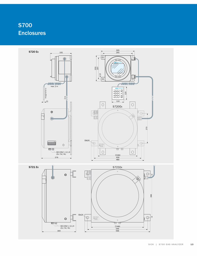
S720 Ex • flame-proof enclosure/intrinsically safe• IP 65 (NEMA 7)• suitable for Ex zone 1 areas• test certificate number: TÜV 97 ATEX 1207 X, EEx
d ia IIC T6 or EEx d ia [ia] IIC T6 w. intrinsically safe signal output*)
• when used in a hazardous area, the valid EC-Type Examination Certificate “TÜV 97 ATEX 1207 X” has to be observed
• purgeable*)
• integrated flame arrestors*) for gas inlet and outlet• intrinsically safe signal outputs*)
• weight: 132...155 lb (60...70 kg) depending on configuration
S721 Ex • special enclosure S720 Ex with a larger housing allows the maximum number of possible configurations
• when used in a hazardous area, the valid EC-Type Examination Certificate “TÜV 97 ATEX 1207 X” has to be observed
• weight: 199...221 lb (90...100 kg) depending on configuration
*) Option
4 S 7 0 0 G A S A N A LY Z E R | S I C K
S700 Common Features
Measuring Value, Status and Control OutputsMeasurement signals (analog)
• 4 measuring value outputs• assigned either to an analyzer module,
calculated value or to an external analog signal*), freely selectable
• 0/4...20 mA or 0...0 V*), linear• potential-free (galvanically isolated)• maximum load 500 Ω,• maximim load 390 Ω with intrinsically safe*)
output• programmable live zero• during the calibration cycle, the output
signal can be selected to either follow the calibration values or to hold the last process measurement value
Output ranges • 2 output ranges*) freely programmable over the basic measuring range
• maximum range switching ratio*) 1:10**), e.g. 400...500 ppm with basic measuring range 0...1,000 ppm ratio 1:20 on request*)
• data sheet specification is valid for the basic measuring range and ordered output ranges*)
Status and control outputs
• 8 relay contacts• 8 open-collector outputs• 3 relay contacts pre-set, all other contacts
can be defined by the user, e.g.: – 4 alarm levels, freely programmable for high or low alarm limits
– fault – service required (NAMUR signal “service required”)
– service/calibration (NAMUR signal “function monitoring”)
– 4 measuring range IDs – 5 signals to control the solenoid valves for manual or automatic calibration for sample, zero and test gases
– manual control of an external sample gas pump and automatic shut-down thereof in the event of a fault: external sample pump ON/OFF
– logic freely selectable
Digital InterfacesRS232C (unidirectional)
• automatic output of measuring value and status with date and time
RS232C (bidirectional)
• limited AK-protocol• remote control via modem or serial PC
direct connection
Measuring Value and Control Inputs
Measurementvalue inputs*)
• 2 inputs• 0/2/4...20 mA or 0...10 V• for cross-sensitivity*) or other signal
computation*)
• shown on LC-Display• output on analog measuring value output
possibleControl inputs • 8 inputs
• ga lvanica l ly iso lated v ia in terna l opto-couplers
• can be freely programmed for different meanings, e.g.:
– calibration control – external measuring range switching – mon i to r ing o f ex te rna l s y s tem components, e.g. cooler, test gas bottles
– s e r v i c e / c a l i b r a t i o n l o c k - o u t (NAMUR-Signal “communication”) to ensure uninterrupted sample analysis
Display and Menu Drive
Display • backlit LC-graphic display 5 in wide, 3.5 in high (120 mm x 90mm)
Measuring value display
• digital, 5-digit 0.7 in high (17.5 mm)• quasi-analog (bar graph)• in engineering units: ppb, ppm, %, mg/3n,
g/m3n, to be specified• measurement value and status messages
are always shown in every menu step
Menu drive • 3 levels according to NAMUR standard• 2 levels are protected against unauthorized
access• context related and explanatory help texts
accessible
Clear text messages
• clear and descriptive text messages: – status conditions
(“calibration”,...) – fault diagnostics
(“gas flow”, “IR source”, ...) – service required (“zero point drift”, ...) etc.
Menu languages • English, German, French, Italian, Spanish, Dutch, Polish, Swedish
*) Option **) FINOR: maximum 1:2
Warranty
Extended Warranty
• no extra charge for 2 year warranty on all parts not in contact with sample gas
5S I C K | S 7 0 0 G A S A N A LY Z E R
S700Data sheet
Gas Inlet and Outlet Conditions
Gas temperature • +32...+113°F (0...+45°C)
Gas quality • dew point of sample gas must be below ambient temperature
• sample gas must be free of dust, parti-cles and aerosol
Sample gas pressure relative to ambient pressure
• tubed gas lines: –200...+1000 hPa• hosed gas lines: –200...+300 hPa • limitations according to Ex approvals pos-
sibleSample gas pump*)
• maximum 16 gal./h (60 l/h) at 100 hPa subpressure
• pump capacity adjust. by software• only for hosed gas lines• limitations according to Ex approvals pos-
sibleSample gas / Reference gas flow rate*)
• without built-in sample pump: 1.3...26.4 gal./h (5...100 l/h)• with built-in sample pump*): 8...16 gal./h (30...60 l/h)• limitations according to Ex approvals
possible
General Data
Line voltage • 100/115 / 230 VAC (+10%, –15%), switchable, fuse change necessary
• 48...62 HzPower consumption
• maximum 150 VA, typically 50 VA, depending on configuration
Ambient temper-ature (operation)
• +41...113°F (+5...+45°C)
Transport and storage temp.
• –4...+158°F (-20...+70°C)
Relative humidity
• humidity class F (DIN 40040) ≤ 75% annual average ≤ 95% occasionally
• non-condensing
Calibration
Automatic • fully automatic at pre-programmed intervals, via manual or via external start signal
• calibration lock-out in critical measuring situations
• only zero gas required when using the calibration cuvette*) (UNOR and MULTOR only) or
• by use of zero and span gases
Manual • only zero gas required when using the calibration cuvette*) (UNOR/MULTOR only) or
• low voltage guidelines 72/23/EC• EN 61326-1, EN 61000-6
Protection class • EN 61010• EN 60529• EN 60950
Hardware Options
Sample gas pump • for sample gas delivery
Stainless steel tubing
• for increased safety
Separate gas lines
• up to 3 separate gas lines possible
Calibration cuvette
• for calibration without the need for span gases (UNOR, MULTOR), only zero gas required
Filter cuvette • for the reduction of cross interference (UNOR, MULTOR)
Fault monitor flow
• for monitoring the gas flow
Fault monitor moisture
• to check for condensate in the sample gas
Barometric pres-sure correction
• to compensate for changes in air pressure
Sample gas pres-sure correction
• to compensate for changes in sample gas pressure
Sample point switch
• for switching between up to 8 sample points with external solenoid valves
*) Option
Gas ConnectionsEnclosure S710Enclosure S711
• PVDF bulkhead fitting for 6 x 1 mm hose• 6 mm SWAGELOK*) stst• ¼” SWAGELOK*)
Enclosure S715Enclosure S720 EXEnclosure S721 EX
• G ¼” inner winding for screw fittings• integrated flame arrestors*) (not available
for S715/S715EX)Screw fittings • 6 mm SWAGELOK*)
• ¼” SWAGELOK*)
• 6 mm PVDF*) for hosed gas lines
Purge Gas ConnectionsEnclosure S715 • 6 mm PVDF*)
• ⅜” SWAGELOK*)
• 8 mm SWAGELOK*)
• 10 mm SWAGELOK*)
Enclosure S720 EXEnclosure S721 EX
• G ¼” inner winding for screw fittings (see gas connections)
6 S 7 0 0 G A S A N A LY Z E R | S I C K
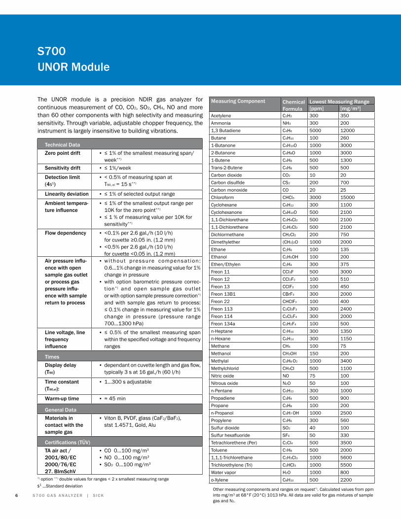
The UNOR module is a precision NDIR gas analyzer for continuous measurement of CO, CO2, SO2, CH4, NO and more than 60 other components with high selectivity and measuring sensitivity. Through variable, adjustable chopper frequency, the instrument is largely insensitive to building vibrations.
Other measuring components and ranges on request*). Calculated values from ppm into mg/m3 at 68°F (20°C) 1013 hPa. All data are valid for gas mixtures of sample gas and N2.
Technical DataZero point drift • ≤ 1% of the smallest measuring span/
week**)
Sensitivity drift • ≤ 1%/week
Detection limit (4s1)
• < 0.5% of measuring span at T90, el = 15 s**)
Linearity deviation • ≤ 1% of selected output range
Ambient tempera-ture influence
• ≤ 1% of the smallest output range per 10K for the zero point**)
• ≤ 1 % of measuring value per 10K for sensitivity**)
Flow dependency • <0.1% per 2.6 gal./h (10 l/h) for cuvette ≥0.05 in. (1.2 mm)
• <0.5% per 2.6 gal./h (10 l/h) for cuvette <0.05 in. (1.2 mm)
Air pressure influ-ence with open sample gas outlet or process gas pressure influ-ence with sample return to process
• wi thout pressure compensat ion : 0.6...1% change in measuring value for 1% change in pressure
• with option barometric pressure correc-tion*) and open sample gas outlet or with option sample pressure correction*) and with sample gas return to process: ≤ 0.1% change in measuring value for 1% change in pressure (pressure range 700...1300 hPa)
Line voltage, line frequency influence
• ≤ 0.5% of the smallest measuring span within the specified voltage and frequency ranges
TimesDisplay delay (T90)
• dependant on cuvette length and gas flow, typically 3 s at 16 gal./h (60 l/h)
Time constant (T90,el):
• 1...300 s adjustable
Warm-up time • ≈ 45 min
General DataMaterials in contact with the sample gas
• Viton B, PVDF, glass (CaF2/BaF2), stst 1.4571, Gold, Alu
Certifications (TÜV)TA air act /2001/80/EC2000/76/EC27. BImSchV
• CO 0...100 mg/m3
• NO 0...100 mg/m3
• SO2 0...100 mg/m3
*) option **) double values for ranges < 2 x smallest measuring ranges1 ...Standard deviation
7S I C K | S 7 0 0 G A S A N A LY Z E R
S700 MULTOR Module
The MULTOR module is a precision NDIR gas analyzer for the continuous measurement of up to 3 IR components. H2O can be measured as 4th component for internal cross sensitivity
correction. The MULTOR has a high selectivity and measuring sensitivity. Through variable, adjustable chopper frequency, the instrument is largely insensitive to building vibrations.
Measuring Components and Lowest Measuring RangesComponent Chemical
FormulaLowest measuring range
Carbon dioxide CO2 100 ppm 200 mg/m3
Carbon monoxide CO 160 ppm 200 mg/m3
Methane CH4 470 ppm 335 mg/m3
Nitric oxide NO 190 ppm 250 mg/m3
Sulfur dioxide SO2 85 ppm 250 mg/m3
Calculated values from ppm to mg/m3 at 68°F (20°C), 1013 hPa. Other measuring components and measuring ranges on request*). All data are valid for gas mixtures of sample gas and flue gas.
General DataMaterials in contact with the sample gas
• Viton B, PVDF, g lass (CaF2/BaF2) , stst 1.4571, gold, alu
Certifications (TÜV)TA air act /2001/80/EC
• CO 0...200 mg/m3
• NO 0...250 mg/m3
• SO2 0...250 mg/m3
Technical DataZero point drift • ≤ 1% of the smallest measuring span/
week**)
Sensitivity drift • ≤ 1%/week
Detection limit (4s1)
• < 0.5% of measuring span at T90, el = 15 s**)
Linearity deviation
• ≤ 2% of the selected measuring span
Ambient temper-ature influence
• zero point: ≤ 1.5% of the measuring span/10 K
• sensitivity: ≤ 2% of the measuring span/10 K
Flow dependency
• <0.1% per 2.6 gal./h (10 l/h) for cuvette ≥0.05 in. (1.2 mm)
• <0.5% per 2.6 gal./h (10 l/h) for cuvette <0.05 in. (1.2 mm)
Air pressure influence with open sample gas outlet or process gas pressure influence with sample return to process
• w i thout p ressure compensat ion : ≤ 1% change in measuring value for 1% change in pressure
• with option barometric pressure correction*) a n d o p e n s a mp l e ga s o u t l e t o r with option sample gas pressure correc-tion*) sample gas return to process: ≤ 0.1% change in measuring value for 1% change in pressure (pressure range 700...1300 hPa)
Line voltage, line frequency influ-ence
• ≤ 0.5% of the smallest measuring span within the specified voltage and frequency ranges
TimesDisplay delay (T90)
• dependant on the cuvette length, gas flow rate and the number of components, maximum 25 s at 16 gal./h (60 l/h)
Time constant (T90, el)
• 1...300 s adjustable
Warm-up time • ≈ 45 min*) option**) double values for ranges < 2 x smallest measuring range
s1 ... Standard deviation
8 S 7 0 0 G A S A N A LY Z E R | S I C K
S700 THERMOR Module
The THERMOR module is a precision thermal conductivity gas analyzer. H2, He, CO2, Ar as well as other gases in binary or quasi-binary mixtures can be measured with high measuring sensitivity. The influence of other components in non-binary gas mixtures can be taken into account by the cross sensitivity correction in case these components are measured with other modules*) or by external measuring devices*). As an option, the analyzer can be configured for monitoring*) of H2 cooled turbine generators.
As special model*) of the measuring cell, a corrosive resistance cell made of PVDF is available.
*) option**) double values for ranges < 2 x smallest measuring ranges1 ... Standard deviation
7
6
5
4
3
2
1
0 Ar CH4 CO C02 C2H6 C3H8 C4H10 C5H12 He H2 H2O Luft NH3 NO N2 N2O O2
Measuring Components and Smallest Measuring RangesComponent in Chemical
formulaMin. meas.range [vol%]
Argon Oxygen Ar in O2 5Nitrogen Ar in N2 5
Ammonia Carbon dioxide NH3 in CO2 15Room air NH3 in air 75
Carbon dioxide Air CO2 in air 10Helium Nitrogen He in N2 1Hydrogen Argon H2 in Ar 1
Air H2 in Air 1Blast furnace gas
H2 , blast furnace gas
1
Carbon monoxide H2 in CO 1Methane H2 in CH4 1Oxygen H2 in O2 1Nitrogen H2 in N2 1
Methane Ferment. gas CH4 in ferment gas 60Other measuring components and suppressed measuring ranges on request
TimesDisplay delay (T90)
• < 20 s at T90,el = 1 s and sample gas flow 16 gal./h (60 l/h)
Time constant (T90, el)
• 1...300 s adjustable
Warm-up time • ≈ 30 min
Option: Cooling Gas MonitoringApplication • monitoring of H2 cooled turbo generators:
during filling/emptying process and during operation for H2 purity
Measuring ranges
• 0...100 vol% CO2 in air• 0...100 vol% H2 in CO2
• 80...100 vol% H2 in airCalibration • for test and zero gas only 100% H2 and
100% CO2 are requiredControl and monitoring functions
• manual range switching• external measuring range switching from
control system• 4 alarm messages freely programmable• high level of up time through automatic
calibration and self-diagnostics
Technical DataZero point drift • ≤ 1% of smallest measuring span/week**)
Sensitivity drift • ≤ 1% per week
Detection limit (4s1)
• < 0.5% of measuring span at T90, el = 15 s**)
Linearity deviation • ≤ 1% of the selected output range
Ambient temperature influence
• ≤ 1% of the smallest measuring span per 10 K for the zero point
• ≤ 1% of the measuring value per 10 K for sensitivity
Flow dependency
• < 0.2% change in measuring value in the range of 2.6...21 gal./h (10...80 l/h for a change in flow of 2.6 gal./h (10 l/h)
• for the smallest measuring ranges: < 0.3% change in measuring value in the range of 2.6...21 gal./h (10 ... 80 l/h) change in flow rate
Atmospheric pressureinfluence
• none
Line voltage, Line frequency influence
• ≤ 0.5% of the smallest measuring span within specified voltage and frequency ranges
Relative thermal conductivity of gases relative to air= 1 at 300°F (150°C)
s1 ... Standard deviation
Technical DataZero point drift • ≤ 1.5% of the smallest measuring
span/week**)
Sensitivity drift • ≤ 1%/week
Detection limit (4s1) • < 0.5% of measuring span at T90, el = 15 s**)
Linearity deviation • ≤ 1.5% of the selected output range
Incline influence • none
Ambient temperature influence
• zero point: ≤ 1.5% of the measuring span/10 K
• sensitivity: ≤ 1.5% of the measuring span/10 K
Flow dependency • < 0.1% change in measuring value in the range of 2.6...21 gal./h (10...80l/h) at 2.6 gal./h (10 l/h) change in flow rate
Air pressure influence with open sample gas outlet or process gas pressure influence with sample return to process
• without pressure compensation: < 1% change in measuring value for 1% change in pressure
• with option barometric pressure correction*) and open sample gas outlet or w i th o p t i o n s a mp l e p re s s u re compensation*) and sample return to process: ≤ 0.1% change in measuring value for 1% change in pressure (pressure range 700...1300 hPa)
Line voltage line frequency influence
• ≤ 0.5% of the smallest measuring span within the specified voltage and frequency ranges
Output ranges • 2 output ranges*) freely programmable over the basic measuring range
• maximum range switching ratio 1:2• data sheet specification is valid for the
basic measuring range and ordered output ranges*)
The FINOR module is a single beam NDIR photometer which operates on the principle of interference filter correlation (IFC). The analyzer can determine up to 3 components in parallel.
The measuring system incorporates a solid-state detector and as such the entire construction is rugged and insensitive to mechanical vibration.
S700 FINOR Module
TimesDisplay delay(T90)
• dependant on the cuvette length, gas flow rate and number of components, maximum 25 s at 16 gal./h (60 l/h)
Time constant (T90, el):
• 1 ... 300 s adjustable
Warm-up time • ≈ 45 min
General DataMaterials in contact with the sample gas
Measuring Components and Smallest Measuring RangesComponent Chem.
formulaSmallest measruing range mg/m3 Vol %
Carbon dioxide CO2 2000 0.1
Carbon monoxide CO 6000 0.5
Hydrocarbons 1) CnHm 2.0
Methane CH4 15000 2.0
Sulfur hexafluoride SF6 10
Calculation from ppm to mg/m3 at 68°F (20°C), 1013 hPa. Other components and measuring ranges on request*). All data are valid for gas mixtures of sample gas and N2.
1) The measurement of hydrocarbons is performed via a broad range filter and allows only for a rough estimation of the existing hydrocarbon concentration.
*) option**) double values for ranges < 2 x smallest measuring range
1 0 S 7 0 0 G A S A N A LY Z E R | S I C K
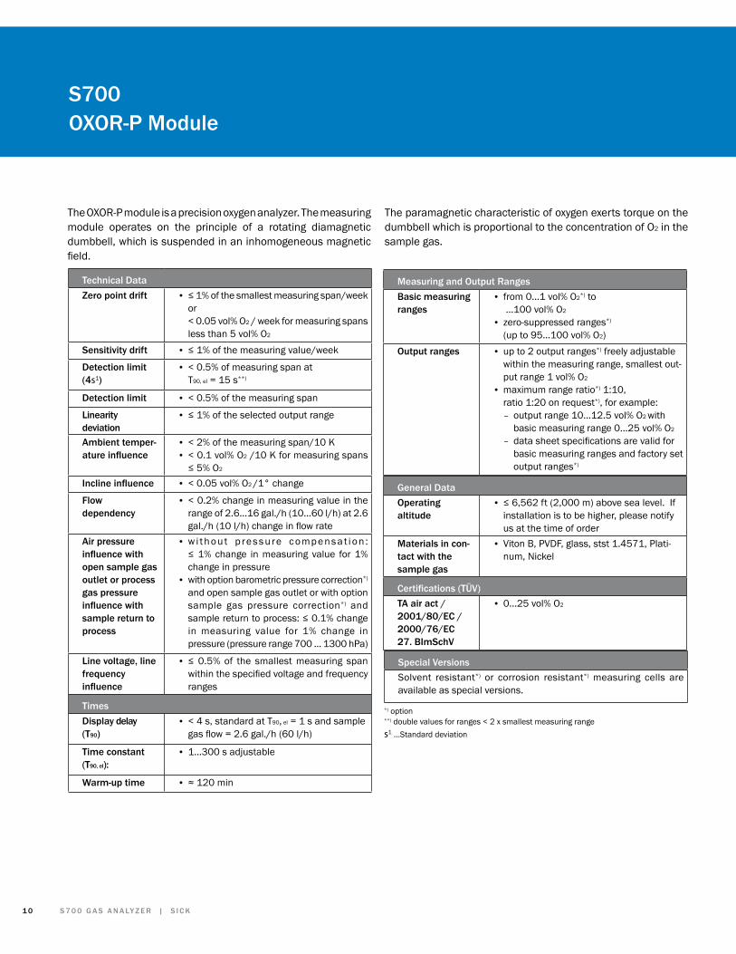
The OXOR-P module is a precision oxygen analyzer. The measuring module operates on the principle of a rotating diamagnetic dumbbell, which is suspended in an inhomogeneous magnetic field.
The paramagnetic characteristic of oxygen exerts torque on the dumbbell which is proportional to the concentration of O2 in the sample gas.
S700 OXOR-P Module
Technical DataZero point drift • ≤ 1% of the smallest measuring span/week
or < 0.05 vol% O2 / week for measuring spans less than 5 vol% O2
Sensitivity drift • ≤ 1% of the measuring value/week
Detection limit (4s1)
• < 0.5% of measuring span at T90, el = 15 s**)
Detection limit • < 0.5% of the measuring span
Linearity deviation
• ≤ 1% of the selected output range
Ambient temper-ature influence
• < 2% of the measuring span/10 K • < 0.1 vol% O2 /10 K for measuring spans
≤ 5% O2
Incline influence • < 0.05 vol% O2 /1° change
Flow dependency
• < 0.2% change in measuring value in the range of 2.6...16 gal./h (10...60 l/h) at 2.6 gal./h (10 l/h) change in flow rate
Air pressure influence with open sample gas outlet or process gas pressure influence with sample return to process
• w i thout p ressure compensat ion : ≤ 1% change in measuring value for 1% change in pressure
• with option barometric pressure correction*) and open sample gas outlet or with option sample gas pressure correction*) and sample return to process: ≤ 0.1% change in measuring value for 1% change in pressure (pressure range 700 ... 1300 hPa)
Line voltage, line frequency influence
• ≤ 0.5% of the smallest measuring span within the specified voltage and frequency ranges
TimesDisplay delay (T90)
• < 4 s, standard at T90, el = 1 s and sample gas flow = 2.6 gal./h (60 l/h)
Time constant (T90, el):
• 1...300 s adjustable
Warm-up time • ≈ 120 min
Measuring and Output RangesBasic measuring ranges
• from 0...1 vol% O2*) to ...100 vol% O2
• zero-suppressed ranges*) (up to 95...100 vol% O2)
Output ranges • up to 2 output ranges*) freely adjustable within the measuring range, smallest out-put range 1 vol% O2
• maximum range ratio*) 1:10, ratio 1:20 on request*), for example:
– output range 10...12.5 vol% O2 with basic measuring range 0...25 vol% O2
– data sheet specifications are valid for basic measuring ranges and factory set output ranges*)
General DataOperating altitude
• ≤ 6,562 ft (2,000 m) above sea level. If installation is to be higher, please notify us at the time of order
Certifications (TÜV)TA air act /2001/80/EC /2000/76/EC27. BImSchV
• 0...25 vol% O2
Special VersionsSolvent resistant*) or corrosion resistant*) measuring cells are available as special versions.
*) option**) double values for ranges < 2 x smallest measuring ranges1 ...Standard deviation
1 1S I C K | S 7 0 0 G A S A N A LY Z E R
The module OXOR-E is a precision oxygen analyzer. It operates using an electrochemical cell for the detection of oxygen.
S700 OXOR-E Module
Technical DataZero point drift • ≤ 2% of the smallest measuring span/
monthSensitivity drift • ≤ 1%/week
Detection limit (4s1)
• < 0.5% of measuring span at T90, el = 15 s**)
Linearity deviation • ≤ 1.5% of the selected measuring span
Incline influence • none
Ambient temper-ature influence
• zero point: ≤ 1.5% of the measuring span/10 K
• sensitivity: ≤ 1.5% of the measuring span/10 K
Flow dependency
• < 0.1% change in measuring value in the range of 2.6...21 gal./h (10...80 l/h) at 2.6 gal./h (10 l/h) change in flow rate
Air pressure influence with open sample gas outlet or process gas pressure influence with sample return to process
• without pressure compensation: < 1% change in measuring value for 1% change in pressure
• with option barometric pressure correction*) and open sample gas outlet or with option sample gas pressure correction*) and sample return to process: ≤ 0.1% change in measuring value for 1% change in pressure (pressure range 700...1300 hPa)
Line voltage,line frequency influence
• ≤ 0.5% of the smallest measuring span within the specified voltage and frequency ranges
TimesDisplay delay (T90)
• dependant on the gas flow rate, typically 20 s at 16 gal./h (60 l/h)
Time constant (T90, el):
• 1...300 s adjustable
Warm-up time • none
Measuring and Output RangesBasic measuring ranges
• 0...25 vol% O2
Smallest measuring range
• 10 vol% O2
Output ranges • up to 2 output ranges*) freely adjustable within the measuring range,
• smallest output range 10 vol% O2
• data sheet specifications are valid for basic measuring ranges and factory ordered out-put ranges*)
General DataMaterials in contact with the sample gas
• Viton B, PVDF, stst 1.4571
Certifications (TÜV)TA air act /2001/80/EC /2000/76/EC27. BImSchV
• 0...25 vol% O2
* Option
s1 ... Standard deviation
1 2 S 7 0 0 G A S A N A LY Z E R | S I C K
S700 Enclosures
Function
Service
Alarm
7 8 9
4 5 6
1 2 3
0
Esc
Help
Enter
483 (19")
442
S711 S710
350
250
375
275
290
390
4213
2.5
(3 H
U)
115
BA DC
5222
82112
X1
X3
X2
X5
X4
X7
X6
S710
A Measuring gas entryB Measuring gas outletC Sample 2D Sample 3
Zone 2
Function
Service
Alarm
7 8 9
4 5 6
1 2 3
0
Esc
Help
Enter
F
(E)
(F)
E
500 (19.69)442 (17.40)
530 (20.87)555 (21.85)
148
(5.8
3)21
0 (8
.27)
380
(14.
96)
415
(16.
34)
445
(17.
52)
470
(18.
50)
357
(14.
06)
30 (
1.18
)
ISO 228/1 - G 1/4
mm (inch)(1.38)
35
288 (11.34)278 (10.94)
S715 E Purge gas entryF Purge gas outlet
1 3S I C K | S 7 0 0 G A S A N A LY Z E R
S700 Enclosures
WARNUNG / WARNINGNach dem Abschaltenmindestens 5 Minutenwarten, bevor dasGerät geöffnet wird!
After power off, wait atleast 5 minutes beforeopening the instrument!
WARNUNG / WARNINGNach dem Abschaltenmindestens 5 Minutenwarten, bevor dasGerät geöffnet wird!
After power off, wait atleast 5 minutes beforeopening the instrument!
Func tion Service Alarm
7 8 9
4 5 6
1 2 3
0
Esc
Help
Enter
360
480
305265
18x24
18x24
276
ma
gn
ete
ic
300
396
270
480
596
430
S 720 Ex
S 721 Ex
546
11
2 m
max. 2 m
ISO 228/1 - G 1/4(2x / 3x / 4x)
ISO 228/1 - G 1/4(2x / 3x / 4x)
110
120
197
ø 13
233
192S720 Ex
WARNUNG / WARNINGNach dem Abschaltenmindestens 5 Minutenwarten, bevor dasGerät geöffnet wird!
After power off, wait atleast 5 minutes beforeopening the instrument!
WARNUNG / WARNINGNach dem Abschaltenmindestens 5 Minutenwarten, bevor dasGerät geöffnet wird!
After power off, wait atleast 5 minutes beforeopening the instrument!
Func tion Service Alarm
7 8 9
4 5 6
1 2 3
0
Esc
Help
Enter
360
480
305265
18x24
18x24
276
ma
gn
ete
ic
300
396
270
480
596
430
S 720 Ex
S 721 Ex
546
11
2 m
max. 2 m
ISO 228/1 - G 1/4(2x / 3x / 4x)
ISO 228/1 - G 1/4(2x / 3x / 4x)
110
120
197
ø 13
233
192
S721 Ex
1 4 S 7 0 0 G A S A N A LY Z E R | S I C K
RTS CTS DTR DSR GND TXD RXD RTS CTSRXDTXDGND
RS 232 C #2
EFEF EF
X2 1 2 3 4 5 6 7 8 9 10 11 12
EF EF EF EFEF EF EF
CTS RTS DSR DTR GND RXD TXD CTS RTSTXDRXDGND
RS 232 C #1
OUT1 OUT2
0/4 ... 20 mA0 ... 500
OUT3 OUT4IN2IN1GND
X7 1 2 3 4 5 6 7 8 9 10 11 12
Am 02 ... 0Am 02 ... 0 0 ... 20 mA0 ... 20 mA0 ... 20 mA0 ... 20 mA
R3EF EF
R4 R5 R6EF EF EFEF EF EFEFEF
R2R1
TR124V2 8RT7RT6RT5RT4RT3RT2RTDNG
EF EF
X6 1 2 3 4 5 6 7 8 9 10 11 12
EF EF EF EF EF EF EF EF
X4 1 2 3 4 5 6 7 8 9 10 11 12
REL1 REL2 REL3 REL4
EF EF EF EF EF EF EF EF EF EF EF EF
24V1GND
Alternative
±5 ... ±24 VDC
EF
X3 1 2 3 4 5 6 7 8 9 10 11 12
CI1CIC CI2 CI3 CI4 CI5 CI6 CI7 CI8
4.7 k 4.7 k 4.7 k 4.7 k 4.7 k 4.7 k 4.7 k 4.7 k
EF EF EF EF EF EF EF EF EFEF
CICGND 24V1
X5 1 2 3 4 5 6 7 8 9 10 11 12
EF EF EF EF EF EF EF EF EF EF EF EF
REL5 REL6 REL7 REL8
S700 Signal Connections
• Keep away from external voltages
• Max. 48 V peak voltage (34 V AC / 48 V DC)• Max. 500 mA• Inductive loads must be equipped with discharging diodes
• Only use internal voltage sources (24 V DC)• Max. 500 mA single• Max. 1000 mA total (TR 1 ... TR 8)• Inductive loads must be equipped with discharging diodes
1 5S I C K | S 7 0 0 G A S A N A LY Z E R
S700Planning Notes
Plant/method/process:
Measured gas details (concentration off all components)Meas. gas min. normal max. Unit*)
Measuring componentsComponents Measuring range Unit*)
*) mg/m3 (stand. state/operation state), ppm, vol%, etc.
min. normal max.Operating temperature: °F °F °F
Operating pressure: hPa hPa hPa
Water dewpoint: °F °F °F
Acid dewpoint: °F °F °F
Ambient temperature: °F °F °F
• Sample point °F °F °F
• Sample gas line °F °F °F
•Analyzer/system °F °F °F
Relative humidity max. per year:% % % %
Solid components in mg/m3
Plant detailsFeed gas (e.g. fuel gas):
Sample point Sample gas line Analyzer/systemv
Quantity Type Granulation
Corrosive components: No Yes, list:
SICK Process Automation DivisionUnited States - Minneapolis, Minnesota | Houston, Texas | 281-436-5100Canada - Calgary, Alberta | Toronto, Ontario | [email protected] | www.sicknorthamerica.com