68
Interconnect Single Table 8 (3785C) Universal Part Number: GS-399-00 Issued 12/99 Reference Configuration #48341502
| Date post: | 22-Feb-2017 |
| Category: |
Technology |
| Upload: | shenzhen-southern-machinery-sales-and-service-co-ltd |
| View: | 701 times |
| Download: | 1 times |

Interconnect Single Table 8(3785C)
Universal Part Number: GS-399-00 Issued 12/99Reference Configuration #48341502

Inserter Solutions
IMCProduct Line
IMCProduct Line
Interconnect Single Table 83785C
Insertion Machine DivisionSpecial Products Group
Insertion Machine Division
Industry-standard through hole, single positioning systems increase flexibility andthoughput.
Variety of insertion head combinations allow for custom assembly solutions.
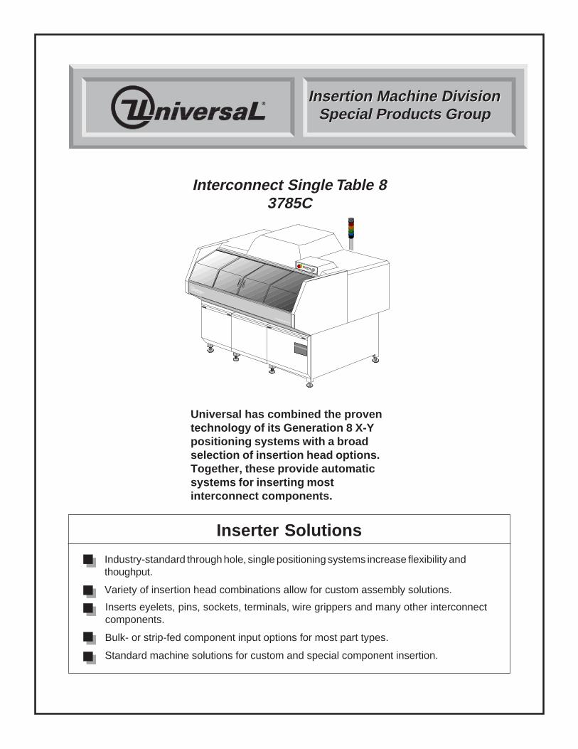
Universal has combined the proventechnology of its Generation 8 X-Ypositioning systems with a broadselection of insertion head options.Together, these provide automaticsystems for inserting mostinterconnect components.
Special Products Group
Inserts eyelets, pins, sockets, terminals, wire grippers and many other interconnect components.
Bulk- or strip-fed component input options for most part types.
Standard machine solutions for custom and special component insertion.

Contents
Introduction ............................................................................................................... 1Standard Features ..................................................................................................... 1
Control System ..................................................................................................... 1Power Input and Distribution ........................................................................... 1Uninterruptible Power Supply (UPS) ............................................................... 1VME Chassis ................................................................................................. 2Input/Output Box ............................................................................................ 3Push Button Panel ......................................................................................... 3
System Software .................................................................................................. 4System Setup ................................................................................................ 4Advanced Product Editor (APE) ..................................................................... 4Product Changeover ....................................................................................... 4Production Control .......................................................................................... 4Machine Status .............................................................................................. 5Management Information ................................................................................ 5IM Diagnostics ............................................................................................... 5On-Line Documentation .................................................................................. 5
CAD Data Requirements ....................................................................................... 6CAD File Requirements .................................................................................. 6Sample CAD File Format Notes ..................................................................... 8Additional APE Features ................................................................................ 8Off-Line Pattern Programming Specifications ................................................. 9
System Mechanics ............................................................................................. 10X-Y Positioning System ............................................................................... 10Machine Console/Covers ............................................................................. 10Machine Status Light/Audible Alarm............................................................. 11
Optional Features .................................................................................................... 12Workboard Holders ............................................................................................. 12Automatic Board Handling Configurations ........................................................... 12Network Kit ......................................................................................................... 13Host Computer Interface Kit ............................................................................... 13Remote P.C. Software/Off-Line Programming ..................................................... 13Remote P.C. ....................................................................................................... 13Board Error Correction (B.E.C.) .......................................................................... 14
Head Selections ...................................................................................................... 15Eyelet Inserters – Bulk Input .............................................................................. 15Pin Inserters – Bulk Input ................................................................................... 15Socket Inserters – Bulk Input ............................................................................. 15Socket Inserters – Tape Input ............................................................................ 16Terminal Inserters – Strip Input .......................................................................... 16Wire Gripper Inserters – Strip Input ..................................................................... 16
Common Machine Configurations ......................................................................... 17Interconnect ST 8 Machine Configurations ......................................................... 17
Process Specifications ........................................................................................... 18Eyelet Specification ............................................................................................ 18Pin Specifications ............................................................................................... 22Socket Specifications ......................................................................................... 26Terminal Inserter Specifications ......................................................................... 29Terminal Insertion Settings ................................................................................. 30Terminal Footprint ............................................................................................... 31Terminal Tooling Considerations ......................................................................... 32Slug Removal System ........................................................................................ 32Part in Place Detection ....................................................................................... 32
GS-399-00 Interconnect Single Table 8

Contents
Custom Terminal Specifications ......................................................................... 33Wire Gripper Specifications ................................................................................ 34
Printed Circuit Board Specifications ..................................................................... 36Workboard Holders ............................................................................................. 37
Special Products Considerations .......................................................................... 38Reliability ............................................................................................................ 38Component Evaluation and Supply ..................................................................... 38Custom Configuration ......................................................................................... 38CE Compliance................................................................................................... 38
Supporting Documents ........................................................................................... 39Machine Dimensions & Weights ............................................................................ 40
Service Requirements (including Uninterruptible Power Supply) .......................... 41Environmental Requirements .............................................................................. 42
Appendix: Automatic Board Handling Systems ................................................. A-43Index ..................................................................................................................... A-43Introduction .......................................................................................................... A-44
Technical Specifications for Internal Board Handling System (BHS) ................A-46Board Handling System (BHS) Tooling and Edge Clearance Specifications ..... A-47Dimensions with BHS ...................................................................................... A-48Technical Specifications for Loader/Unloader: Elevator/Buffer Configuration ... A-49Magazine Elevators ......................................................................................... A-49Magazine Input/Output Buffers ........................................................................ A-49Magazines ....................................................................................................... A-50Universal Magazine Specifications .................................................................. A-51Magazine-to-Magazine Configuration, with Long Buffers .................................. A-52Magazine-to-Magazine Configuration, with Short Buffers ................................. A-53Technical Specifications for Loader/Unloader: Vacuum BareBoard-to-Magazine Configuration ..................................................................... A-54Magazine-to-Magazine Configuration, with 22" Conveyor and Long Buffer ....... A-55Magazine-to-Magazine Configuration, with 22" Conveyor and Short Buffer ...... A-56Technical Specifications for Loader/Unloader: Destacker/Conveyor-to-MagazineConfiguration ................................................................................................... A-57Destacker/Conveyor Configuration, with Long Buffer ....................................... A-58Destacker/Conveyor Configuration, with Short Buffer....................................... A-59Installation Considerations: Loader/Unloader ................................................... A-60Service Requirements ..................................................................................... A-61
Interconnect Stingle Table 8 GS-399-00

All specifications are subject to periodic review and may be changed withoutnotice. Illustrations may not be drawn to scale.
© Universal Instruments Corporation, 1999. All rights reserved.
The following are trademarks of Universal Instruments Corporation, registeredU.S. Patent and Trademark Office: Universal, U-Design logo.
GS-399-00 Interconnect Single Table 8

Acronym/Term MeaningAC Alternating Current: type of electrical power generationAPE Advanced Product Editor (Universal brand name)ASCII American National Standard Code for Information InterchangeAWG American Wire Gauge: wire size standardBEC Board Error Correction (Universal brand name)BHS Board Handling System: means of transporting PCBsCAD Computer-Aided DesignCD-ROM Compact Disc-Read Only MemoryCE Conformité Europeanne: European safety standardCFM Cubic Feet per Minute: measurement of air flowCPH Components per HourCTA Component Transfer AssemblyDC Direct Current: type of electrical power generationERV Expanded Range Component Verifier (Universal brand name)GEM Generic Equipment ModelGS General Specification (Universal brand name)GUI Graphical User InterfaceHSMS High Speed SECS Message Service:
implements SECS2 messaging over a network linkHz Hertz (cycles per second): measurement of electrical frequencyIM Insertion Machine: equipment for through hole component insertionIMC Insertion Machine ComponentsIM-UPS Insertion Machine-Universal Platform Software (Universal brand name): operating
software for Universal Series 8 through hole equipmentI/O Input/OutputIP Index of Protection: resistance of machine to contamination by foreign objectsLED Light Emitting Diode: electrical componentMIT Machine Interface Translator (VME to I/O bus)MMIT Mini Machine Interface Translator (VME to I/O bus)OS/2® Operating System 2 (IBM Corp. brand name)PAC Positive Axis ControlP.C. Personal ComputerPCB (or PC board) Printed Circuit BoardPPM Parts Per Million: measurement of machine performanceSCFM Standard Cubic Feet per Minute: measurement of air flowSECS Semiconductor Equipment Communications Standard: interface between host
computer and assembly machinesSEMI Semiconductor Equipment & Materials InternationalSMC Surface Mount ComponentsSMEMA Surface Mount Equipment Manufacturers AssociationTCP/IP Transfer Control Protocol/Internet Protocol: network communication protocolUCT Universal Control Terminal (Universal brand name): personal computer for operat-
ing IM equipmentUICS Universal Instruments Control Software (Universal brand name)UPS Uninterruptible Power SupplyVA Volt-Amps: measurement of electrical power consumptionVAC Volts Alternating CurrentVDC Volts Direct CurrentVGA Video Graphics Array: type of CRT monitor standardVME® Versa Module Eurocard (Motorola brand name): industry standard for 32-bit
Glossary of Acronyms and Specialized Terms
Interconnect Single Table 8 GS-399-00
Page 1GS-399-00
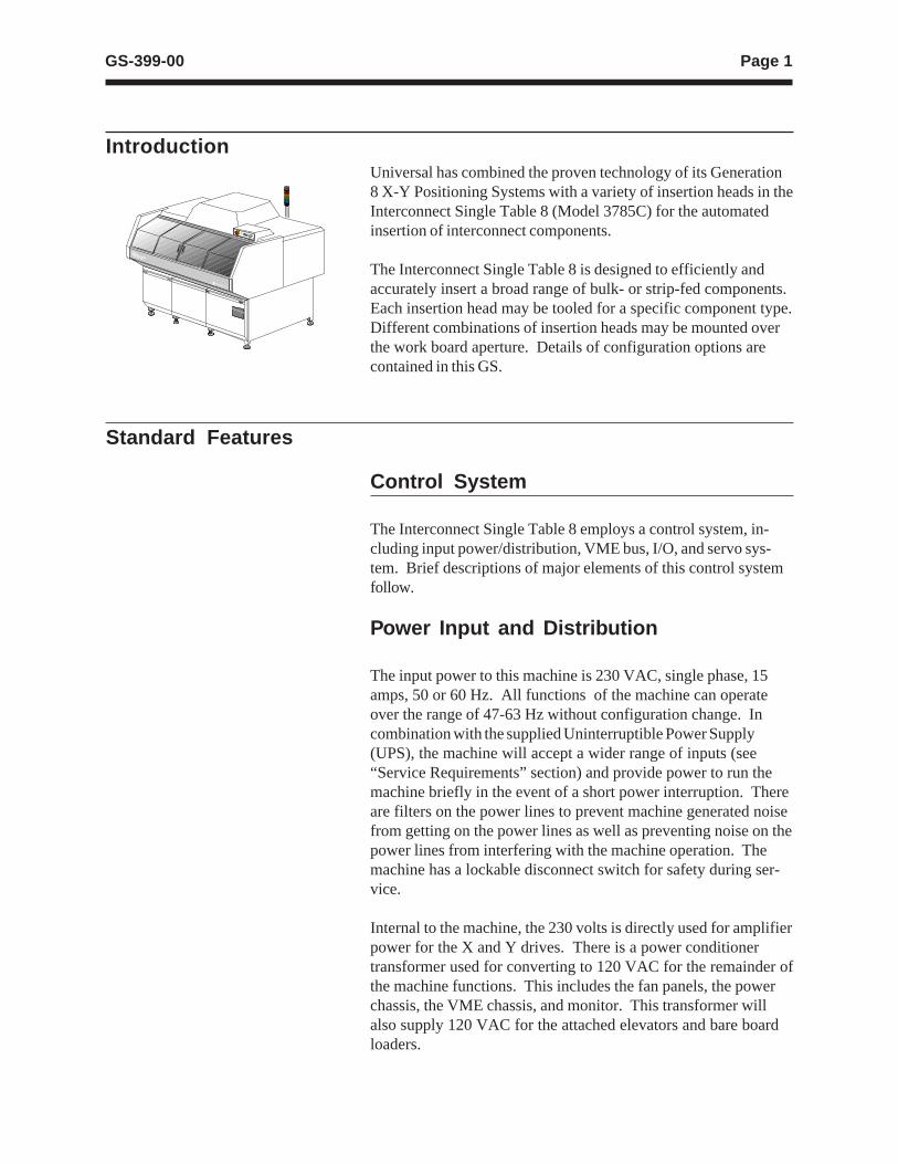
Universal has combined the proven technology of its Generation8 X-Y Positioning Systems with a variety of insertion heads in theInterconnect Single Table 8 (Model 3785C) for the automatedinsertion of interconnect components.
The Interconnect Single Table 8 is designed to efficiently andaccurately insert a broad range of bulk- or strip-fed components.Each insertion head may be tooled for a specific component type.Different combinations of insertion heads may be mounted overthe work board aperture. Details of configuration options arecontained in this GS.
Introduction
Standard Features
Control System
The Interconnect Single Table 8 employs a control system, in-cluding input power/distribution, VME bus, I/O, and servo sys-tem. Brief descriptions of major elements of this control systemfollow.
Power Input and Distribution
The input power to this machine is 230 VAC, single phase, 15amps, 50 or 60 Hz. All functions of the machine can operateover the range of 47-63 Hz without configuration change. Incombination with the supplied Uninterruptible Power Supply(UPS), the machine will accept a wider range of inputs (see“Service Requirements” section) and provide power to run themachine briefly in the event of a short power interruption. Thereare filters on the power lines to prevent machine generated noisefrom getting on the power lines as well as preventing noise on thepower lines from interfering with the machine operation. Themachine has a lockable disconnect switch for safety during ser-vice.
Internal to the machine, the 230 volts is directly used for amplifierpower for the X and Y drives. There is a power conditionertransformer used for converting to 120 VAC for the remainder ofthe machine functions. This includes the fan panels, the powerchassis, the VME chassis, and monitor. This transformer willalso supply 120 VAC for the attached elevators and bare boardloaders.
Page 2 GS-399-00
The power chassis, in turn, provides DC power for machine op-eration. This includes 56 VDC for the board handling motors; +5and ±15 VDC for the I/O box; and 12 VDC for general purposeuse (valve solenoids, sensors, indicators, etc.). The 56 VDC andswitched 12 VDC are disconnected from the machine when in-terlocks are violated. The power chassis also provides 12 VACfor the worklight and 24 VAC for the machine status light andthe interlock circuits.
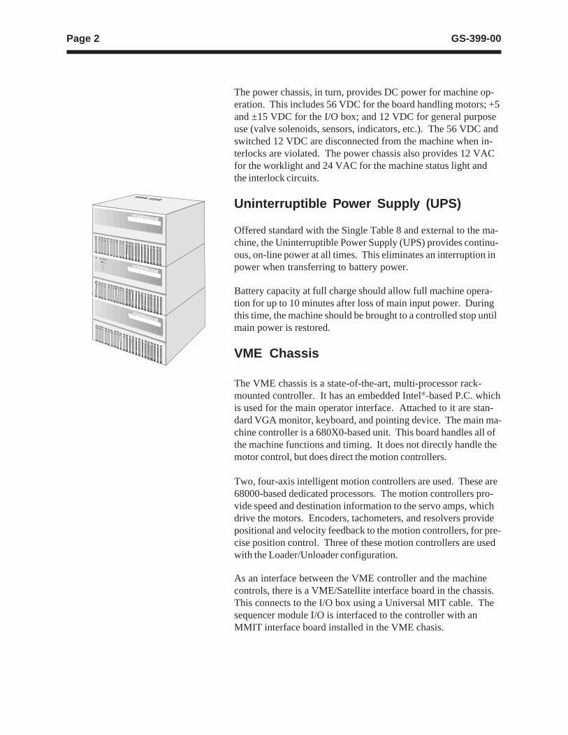
Uninterruptible Power Supply (UPS)
Offered standard with the Single Table 8 and external to the ma-chine, the Uninterruptible Power Supply (UPS) provides continu-ous, on-line power at all times. This eliminates an interruption inpower when transferring to battery power.
Battery capacity at full charge should allow full machine opera-tion for up to 10 minutes after loss of main input power. Duringthis time, the machine should be brought to a controlled stop untilmain power is restored.
VME Chassis
The VME chassis is a state-of-the-art, multi-processor rack-mounted controller. It has an embedded Intel®-based P.C. whichis used for the main operator interface. Attached to it are stan-dard VGA monitor, keyboard, and pointing device. The main ma-chine controller is a 680X0-based unit. This board handles all ofthe machine functions and timing. It does not directly handle themotor control, but does direct the motion controllers.
Two, four-axis intelligent motion controllers are used. These are68000-based dedicated processors. The motion controllers pro-vide speed and destination information to the servo amps, whichdrive the motors. Encoders, tachometers, and resolvers providepositional and velocity feedback to the motion controllers, for pre-cise position control. Three of these motion controllers are usedwith the Loader/Unloader configuration.
As an interface between the VME controller and the machinecontrols, there is a VME/Satellite interface board in the chassis.This connects to the I/O box using a Universal MIT cable. Thesequencer module I/O is interfaced to the controller with anMMIT interface board installed in the VME chasis.
Page 3GS-399-00
Input/Output Box
The I/O box has a standard Universal MIT card in slot 1, whichis the interface to the VME controller. The I/O box contains twoMulti-Input cards, two 32 DC Output cards, a Board Error Cor-rection card, and, for machines with board handling, a 32/16I/O card. An additional 32 DC Input card and 32 DC Outputcard are used for machines with the Loader/Unloader configura-tion.
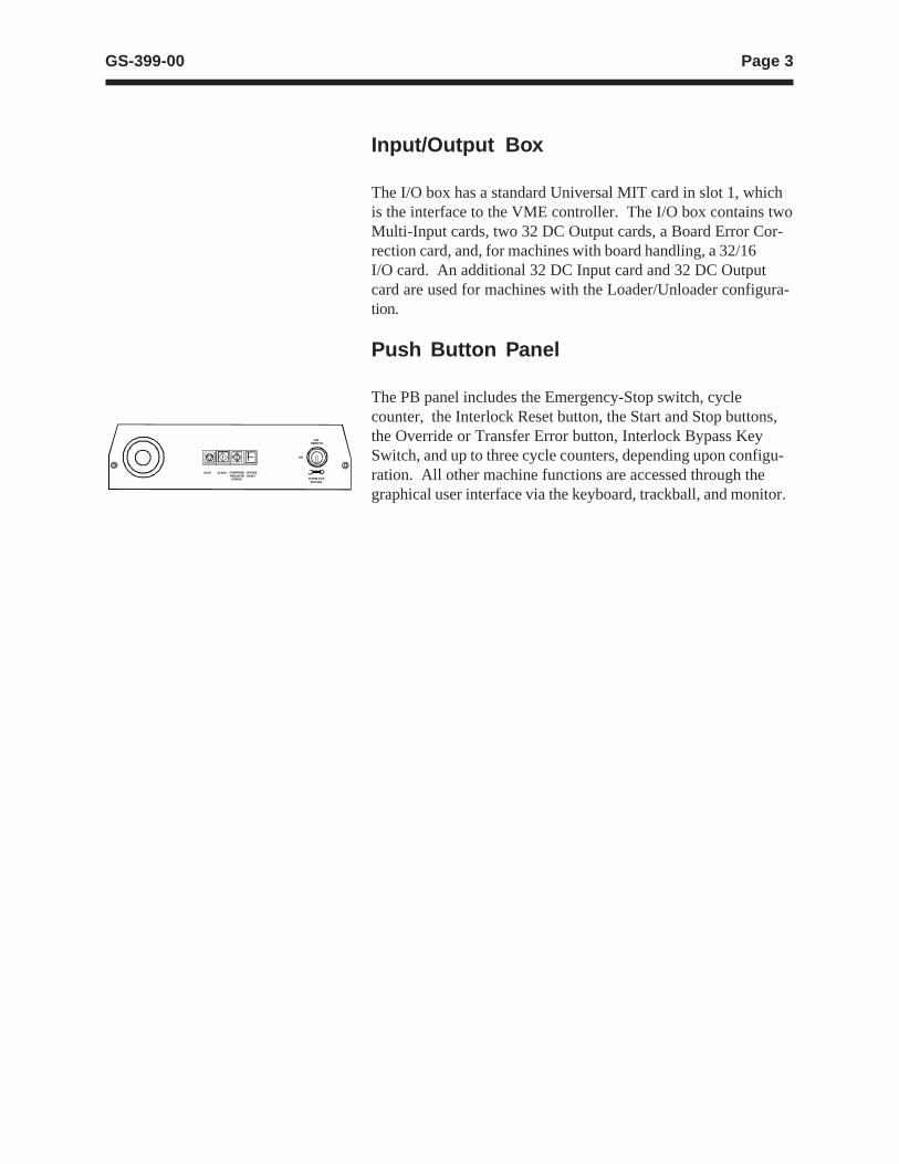
Push Button Panel
The PB panel includes the Emergency-Stop switch, cyclecounter, the Interlock Reset button, the Start and Stop buttons,the Override or Transfer Error button, Interlock Bypass KeySwitch, and up to three cycle counters, depending upon configu-ration. All other machine functions are accessed through thegraphical user interface via the keyboard, trackball, and monitor.
STOP START OVERRIDE/TRANSFER ERROR
INTAKERESET
OFFREMOVE
ON
INTERLOCK BYPASS
Page 4 GS-399-00
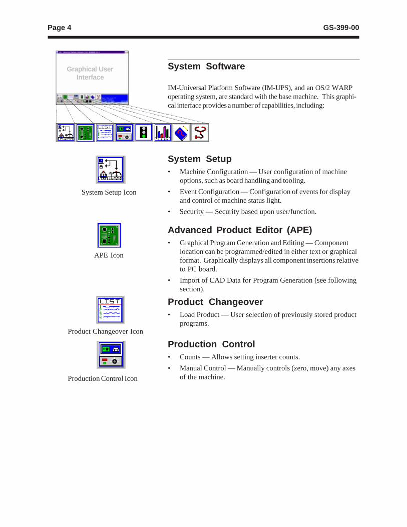
System Software
IM-Universal Platform Software (IM-UPS), and an OS/2 WARPoperating system, are standard with the base machine. This graphi-cal interface provides a number of capabilities, including:
System Setup• Machine Configuration — User configuration of machine
options, such as board handling and tooling.
• Event Configuration — Configuration of events for displayand control of machine status light.
• Security — Security based upon user/function.
Advanced Product Editor (APE)• Graphical Program Generation and Editing — Component
location can be programmed/edited in either text or graphicalformat. Graphically displays all component insertions relativeto PC board.
• Import of CAD Data for Program Generation (see followingsection).
Graphical UserInterface
System Setup Icon
APE Icon
Product Changeover• Load Product — User selection of previously stored product
programs.
Production Control• Counts — Allows setting inserter counts.
• Manual Control — Manually controls (zero, move) any axesof the machine.
Product Changeover Icon
Production Control Icon
Page 5GS-399-00
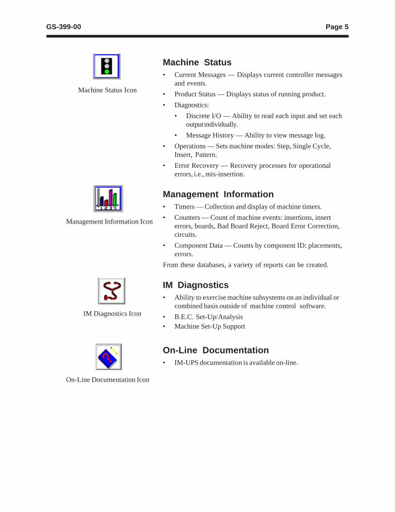
Machine Status Icon
Management Information Icon
IM Diagnostics Icon
Machine Status• Current Messages — Displays current controller messages
and events.
• Product Status — Displays status of running product.
• Diagnostics:
• Discrete I/O — Ability to read each input and set eachoutput individually.
• Message History — Ability to view message log.
• Operations — Sets machine modes: Step, Single Cycle,Insert, Pattern.
• Error Recovery — Recovery processes for operationalerrors, i.e., mis-insertion.
Management Information• Timers — Collection and display of machine timers.
• Counters — Count of machine events: insertions, inserterrors, boards, Bad Board Reject, Board Error Correction,circuits.
• Component Data — Counts by component ID: placements,errors.
From these databases, a variety of reports can be created.
IM Diagnostics• Ability to exercise machine subsystems on an individual or
combined basis outside of machine control software.
• B.E.C. Set-Up/Analysis
On-Line Documentation Icon
• Machine Set-Up Support
On-Line Documentation• IM-UPS documentation is available on-line.
Page 6 GS-399-00
CAD Data RequirementsASCII File Format — Incoming CAD files must conform tothe American National Standard Code for InformationInterchange (ASCII). In order to accommodate a widevariety of CAD file formats, the APE uses either a genericcolumnar or separator data translation technique. All datacontained in the CAD file is identified by a position in adefinition created by the user.
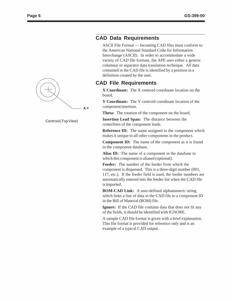
CAD File RequirementsX Coordinate: The X centroid coordinate location on theboard.
Y Coordinate: The Y centroid coordinate location of thecomponent insertion.
Theta: The rotation of the component on the board.
Insertion Lead Span: The distance between thecenterlines of the component leads.
Reference ID: The name assigned to the component whichmakes it unique to all other components in the product.
Component ID: The name of the component as it is foundin the component database.
Alias ID: The name of a component in the database towhich this component is aliased (optional).
Feeder: The number of the feeder from which thecomponent is dispensed. This is a three-digit number (001,117, etc.). If the feeder field is used, the feeder numbers areautomatically entered into the feeder list when the CAD fileis imported.
BOM-CAD Link: A user-defined alphanumeric stringwhich links a line of data in the CAD file to a component IDin the Bill of Material (BOM) file.
Ignore: If the CAD file contains data that does not fit anyof the fields, it should be identified with IGNORE.
A sample CAD file format is given with a brief explanation.This file format is provided for reference only and is anexample of a typical CAD output.
Centroid (Top View)
Page 7GS-399-00
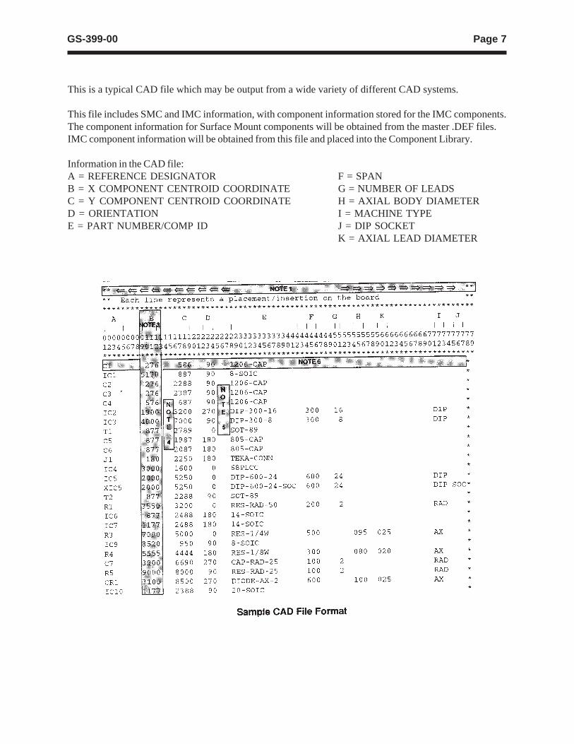
This is a typical CAD file which may be output from a wide variety of different CAD systems.
This file includes SMC and IMC information, with component information stored for the IMC components.The component information for Surface Mount components will be obtained from the master .DEF files.IMC component information will be obtained from this file and placed into the Component Library.
Information in the CAD file:A = REFERENCE DESIGNATOR F = SPANB = X COMPONENT CENTROID COORDINATE G = NUMBER OF LEADSC = Y COMPONENT CENTROID COORDINATE H = AXIAL BODY DIAMETERD = ORIENTATION I = MACHINE TYPEE = PART NUMBER/COMP ID J = DIP SOCKET
K = AXIAL LEAD DIAMETER

Page 8 GS-399-00
Sample CAD File Format Notes1. Maximum file width can not exceed 256 columns.
2. Headerlines, often output by the CAD system, may be used.The CAD Translator allows the user to define the quantity oflines containing the file header. This information is foroperator use only and is not used by the CAD Translator.
3. Format Type: The format of file. This can be either Tableor Separator format (Table is the default).
Table format uses predefined columns for each data type. Forexample, the reference ID column may be defined as 10 characters.The actual reference ID in the CAD file can contain up to 10characters. It does not matter if there is data in every column.
Separator format uses a character (comma, space, dash, etc.) toseparate data fields. Each line of data must contain the samedata types in order for auto detect to work.
# of Fields: The number of fields in the file.
# of Lines: The total number of lines in the file.
4. The CAD file must be devoid of all special control characterssuch as Tabs. (Note that special characters shown are forillustration purposes only and cannot be contained in theactual CAD file. These characters include boxes, arrows.)
5. CAD data is limited to one component per data file line orrow. Additional components are specified on additional linesof the CAD file. There must be no blank lines or rowsbetween any rows of CAD data. Markers such as {EOF}must not be present at the end of the CAD file.
Additional APE Features• Import of Existing UICS Patterns — UICS patterns are
converted to IM-UPS products.
• Program Optimization — Optimization via “NearestNeighbor” insertion path.
• Component Identifier and Reference Designator in ProductInformation — The addition of component identifier andreference designator in programs supports improved statusmessage reporting and management data tracking bycomponentidentifier.

Page 9GS-399-00
Off-Line Pattern ProgrammingSpecificationsThe creation of a “product” (pattern program) can be completedon-line, utilizing the machine’s embedded P.C., or off-line, using asuitable stand-alone P.C. loaded with IM-UPS software.
Note: IM-UPS software supplied with the machine is licensedonly for use in the machine. Software for an off-line P.C.is available as an option at extra cost.
Universal recommends that pattern programming be generatedoff-line to eliminate production interruptions. The stand-aloneP.C. and IM-UPS software for off-line pattern program genera-tion are not standard features of the machine, but can be pur-chased as extra cost options.
Minimum P.C. requirements for creating the product off-line(pattern programming) include:• 486 processor
• 12 megabyte memory
• CD-ROM drive
• IBM OS/2 Warp 3.0
• 200 megabyte available disc space, on OS/2-compatiblepartition
For optimum performance in generating the pattern programmingoff-line, the following capabilities are recommended:• Intel Pentium® processor
• 16 megabyte memory
• 500 megabyte available disc space, on OS/2-compatiblepartition
Note: Installation of OS/2 on an existing P.C. system may re-quire partitioning of the hard drive.
Page 10 GS-399-00
System Mechanics
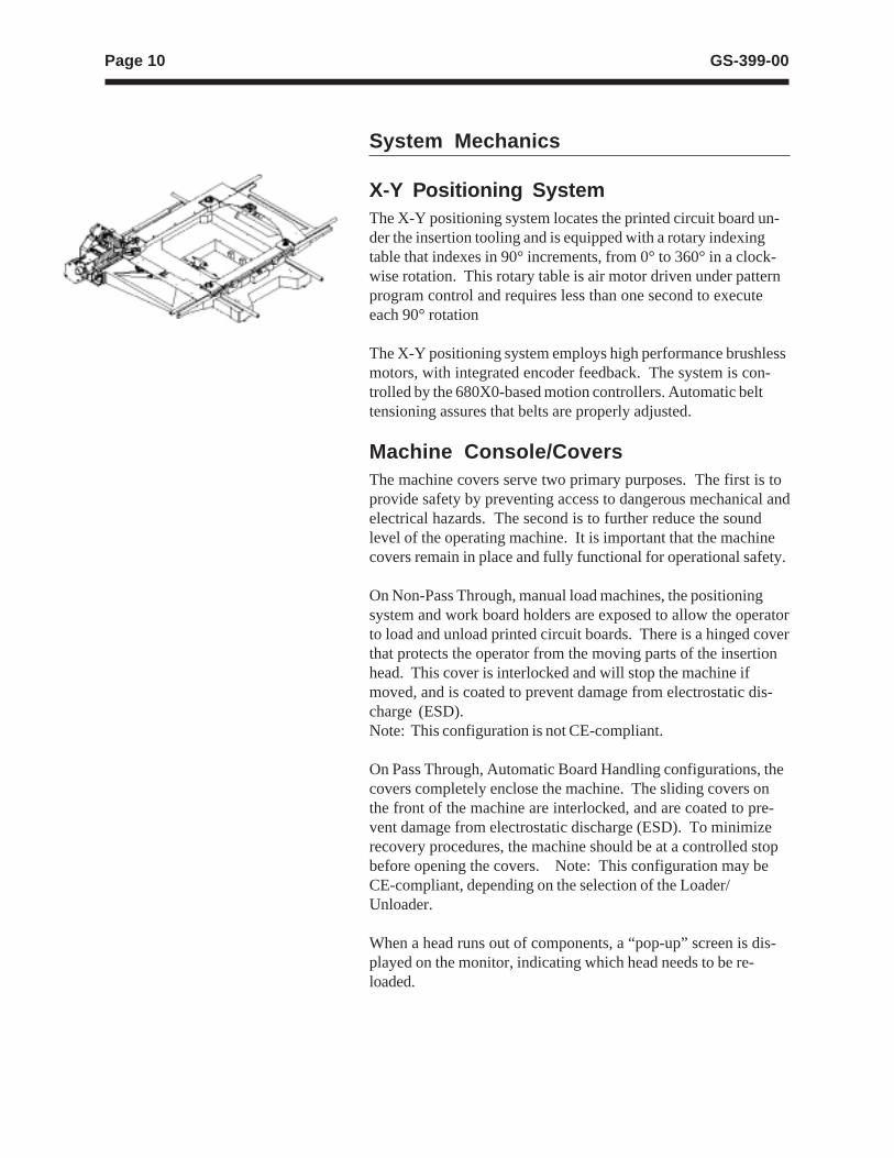
X-Y Positioning SystemThe X-Y positioning system locates the printed circuit board un-der the insertion tooling and is equipped with a rotary indexingtable that indexes in 90° increments, from 0° to 360° in a clock-wise rotation. This rotary table is air motor driven under patternprogram control and requires less than one second to executeeach 90° rotation
The X-Y positioning system employs high performance brushlessmotors, with integrated encoder feedback. The system is con-trolled by the 680X0-based motion controllers. Automatic belttensioning assures that belts are properly adjusted.
Machine Console/CoversThe machine covers serve two primary purposes. The first is toprovide safety by preventing access to dangerous mechanical andelectrical hazards. The second is to further reduce the soundlevel of the operating machine. It is important that the machinecovers remain in place and fully functional for operational safety.
On Non-Pass Through, manual load machines, the positioningsystem and work board holders are exposed to allow the operatorto load and unload printed circuit boards. There is a hinged coverthat protects the operator from the moving parts of the insertionhead. This cover is interlocked and will stop the machine ifmoved, and is coated to prevent damage from electrostatic dis-charge (ESD).Note: This configuration is not CE-compliant.
On Pass Through, Automatic Board Handling configurations, thecovers completely enclose the machine. The sliding covers onthe front of the machine are interlocked, and are coated to pre-vent damage from electrostatic discharge (ESD). To minimizerecovery procedures, the machine should be at a controlled stopbefore opening the covers. Note: This configuration may beCE-compliant, depending on the selection of the Loader/Unloader.
When a head runs out of components, a “pop-up” screen is dis-played on the monitor, indicating which head needs to be re-loaded.

Page 11GS-399-00
Machine Status Light/Audible AlarmThe machine status light/audible alarm indicates the status of ma-chine operation. Each of the lights are user configurable via themachine software. Defaults are set as follows:
• Red - machine stop for any error.
• Yellow - normal operation, machine waiting.
• Green - normal operation, machine running.
• Blue - not configured for Interconnect ST 8.
• Audible alarm - activated for low parts warning.
Page 12 GS-399-00
Optional FeaturesWorkboard Holders
Workboard holders are required to accurately secure PC boardsto the rotary table during the insertion process when manual PCBload/unload is being considered. Universal provides a wide rangeof workboard holder products which can be ordered separately orwith a new machine purchase. For stand-alone operation eithercustom or adjustable fixtures are available with 508mm x 470mm(20" x 18.5") insertion areas.
Note: Insertable area may vary, depending upon head configura-tion.
Automatic Board Handling Configurations
The Interconnect ST 8 machines are available in several materialhandling configurations (left-to-right, or right-to-left):
n Loader/Unloader: Magazine-to-Magazine with Short Buffer(not CE-compliant), or with Long Buffer with extra costcovers (CE-compliant).
n Loader/Unloader: Vacuum Bare Board-to-Magazine withShort Buffer (not CE-compliant), or with Long Buffer (notCE-compliant).
n Loader/Unloader: PCB Destacker-to-Magazine.
• Destacker on 29" Conveyor with Short or Long Buffer(not CE-compliant).
• Destacker on 44" Conveyor with Short Buffer (not CE-compliant).
• Destacker on 44" Conveyor with Long Buffer with extracost covers. Input PCBs, including any installedcomponents, can not exceed 25.4mm (1") thickness (CE-compliant).
• Destacker on 58" Conveyor with Long Buffer with extracost covers (CE-compliant).
n Internal Board Handling System (BHS) - Internal BHS forin-line systems integration is also available. Two PC boards,one for input and one for output, quickly and reliably transfer.Board transfer from last insertion to first insertion on the nextboard occurs in 5.0 seconds. Transfer direction may bespecified when ordering the machine, prior to manufacture,and quick and easy manual width adjustment handles a widerange of PC board sizes. The front fixed rail is standard andall operator PC board changeover adjustments are readilyaccessible.

Page 13GS-399-00
Network Kit
Package for connection includes an Ethernet network card andIBM OS/2 TCP/IP client software. This provides high speed, re-liable communications and data transfer to all computers con-nected to the network.
Host Computer Interface Kit
This kit is used to interface the Interconnect ST 8 with a Hostcomputer using the SECS/GEM Standard. The Generic Equip-ment Model (GEM) Standard defines a standard implementationof the SECS II (Semi Equipment Communications Standard 2)communications interface for all semiconductor manufacturingequipment. See SEMI International Standards document E30-93for details. Note: Requires customer’s Host computer to becompliant with SECS/GEM standard SEMI E37, HSMS, and re-quires the Network Interface Kit.
Remote P.C. Software/Off-LineProgramming
Each base machine includes software licensed only to the ma-chine. Universal recommends that “product” programs be cre-ated off-line to ensure maximum use of machine production time.This off-line software is licensed for use on a P.C. whose basicconfiguration is as shown in the “Off-Line Pattern ProgrammingSpecifications” found in this document.
Remote P.C.
The Universal Control Terminal (UCT), using optional IM-UPSsoftware, allows a Universal approved personal computer to beused as an intelligent terminal. It is connected to the Intercon-nect ST 8 via the optional Network Kit. This package includes avisual display terminal, keyboard, data storage unit, printer andstand, cable assembly, and manual. For additional information onthis option, refer to GS-319. This can be used for off-line pro-gramming and machine data transfer.

Page 14 GS-399-00
Board Error Correction (B.E.C.)
Board Error Correction allows the positioning system to compen-sate for lead hole location variations between printed circuitboard lots. A light source and sensor are mounted relative to theinsertion tooling centerline.
On a maximum dimension PC board — 508mm x 470mm (20" x18.5") — a small area cannot be sensed due to sensor offset.The actual area will vary depending on head selection and con-figuration. A typical detectable area is 508mm x 434.34mm (20"x 17.1") (See section in Technical Specifications on BEC Detec-tion Area).
B.E.C. uses a four quadrant sensor and amplitude controlled lightsource to find the center of holes in printed circuit boards. Thesignals are processed and provide the X and Y corrections to themotion controller via an analog signal, as well as to the span axisfor its correction. The motion controller has 8 bit analog-to-digitalconverters to receive the information. The motion controller thenuses the full power of the control algorithms to find the center ofthe hole. Screens for B.E.C. setup are now integrated into ma-chine diagnostics.
B.E.C. is also used in “Teach” to fit an insertion pattern to a PCboard. This greatly improves pattern accuracy and reduces in-sertion PPM.
Page 15GS-399-00
Different head types may be selected to suit specificapplications. Heads may also be configured as noted in theconfiguration tables. Standard selections include:
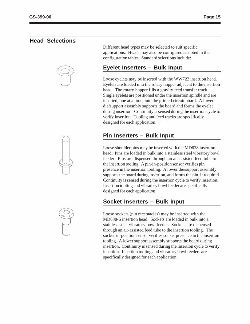
Loose eyelets may be inserted with the WW722 insertion head.Eyelets are loaded into the rotary hopper adjacent to the insertionhead. The rotary hopper fills a gravity feed transfer track.Single eyelets are positioned under the insertion spindle and areinserted, one at a time, into the printed circuit board. A lowerdie/support assembly supports the board and forms the eyeletduring insertion. Continuity is sensed during the insertion cycle toverify insertion. Tooling and feed tracks are specificallydesigned for each application.
Pin Inserters – Bulk Input
Loose shoulder pins may be inserted with the MD838 insertionhead. Pins are loaded in bulk into a stainless steel vibratory bowlfeeder. Pins are dispensed through an air-assisted feed tube tothe insertion tooling. A pin-in-position sensor verifies pinpresence in the insertion tooling. A lower die/support assemblysupports the board during insertion, and forms the pin, if required.Continuity is sensed during the insertion cycle to verify insertion.Insertion tooling and vibratory bowl feeder are specificallydesigned for each application.
Socket Inserters – Bulk Input
Loose sockets (pin receptacles) may be inserted with theMD838-S insertion head. Sockets are loaded in bulk into astainless steel vibratory bowl feeder. Sockets are dispensedthrough an air-assisted feed tube to the insertion tooling. Thesocket-in-position sensor verifies socket presence in the insertiontooling. A lower support assembly supports the board duringinsertion. Continuity is sensed during the insertion cycle to verifyinsertion. Insertion tooling and vibratory bowl feeders arespecifically designed for each application.
Head Selections
Eyelet Inserters – Bulk Input
Page 16 GS-399-00
Terminal Inserters – Strip Input
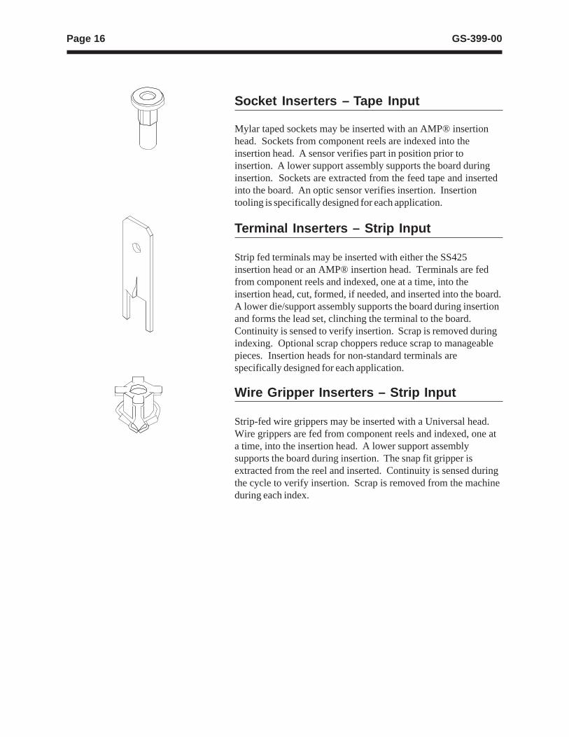
Strip fed terminals may be inserted with either the SS425insertion head or an AMP® insertion head. Terminals are fedfrom component reels and indexed, one at a time, into theinsertion head, cut, formed, if needed, and inserted into the board.A lower die/support assembly supports the board during insertionand forms the lead set, clinching the terminal to the board.Continuity is sensed to verify insertion. Scrap is removed duringindexing. Optional scrap choppers reduce scrap to manageablepieces. Insertion heads for non-standard terminals arespecifically designed for each application.
Wire Gripper Inserters – Strip Input
Strip-fed wire grippers may be inserted with a Universal head.Wire grippers are fed from component reels and indexed, one ata time, into the insertion head. A lower support assemblysupports the board during insertion. The snap fit gripper isextracted from the reel and inserted. Continuity is sensed duringthe cycle to verify insertion. Scrap is removed from the machineduring each index.
Socket Inserters – Tape Input
Mylar taped sockets may be inserted with an AMP® insertionhead. Sockets from component reels are indexed into theinsertion head. A sensor verifies part in position prior toinsertion. A lower support assembly supports the board duringinsertion. Sockets are extracted from the feed tape and insertedinto the board. An optic sensor verifies insertion. Insertiontooling is specifically designed for each application.
Page 17GS-399-00
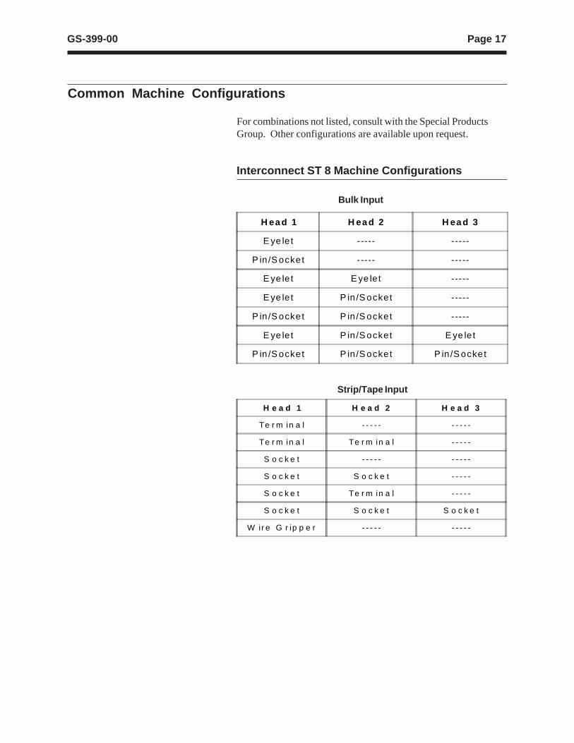
Common Machine Configurations
For combinations not listed, consult with the Special ProductsGroup. Other configurations are available upon request.
Interconnect ST 8 Machine Configurations
Bulk Input
H ea d 1 H ea d 2 H ea d 3
E ye le t ----- -----
P in /S ocket ----- -----
E ye le t E ye le t -----
E ye le t P in /S ocket -----
P in /S ocket P in /S ocket -----
E ye le t P in /S ocket E ye le t
P in /S ocket P in /S ocket P in /S ocket
Strip/Tape Input
H e a d 1 H e a d 2 H e a d 3
Te r m in a l - - - - - - - - - -
Te r m in a l Te r m in a l - - - - -
S o c k e t - - - - - - - - - -
S o c k e t S o c k e t - - - - -
S o c k e t Te r m in a l - - - - -
S o c k e t S o c k e t S o c k e t
W ir e G r ip p e r - - - - - - - - - -
Page 18 GS-399-00
Process Specifications
Eyelet SpecificationBarrel Diameter 1.50mm to 3.18mm (0.059" to 0.125")
± 0.05mm (0.002"), standard 3.18mm to 4.75mm (0.125" to 0.187"), optional
Hole in Circuit ± 0.05mm (0.002") Minimum hole must beBoard 0.20mm (0.008") above Eyelet maximum.
Inside (Pucker) ± 0.05mm (± 0.002")Diameter
Length Under 2.29mm to 5.08mm (0.09" to 0.20") ± 0.13mmFlange (0.005") A minimum 110% length under flange
vs. barrel diameter is recommended to maintain feed rates.
Flange Diameter ± 0.13mm (0.005")
Flange Height ± 0.05mm (0.002")
Flange Type Roll, flat, or funnel (feed rate may be lower).
Maximum Setting 136kg at 5.5 bar (300 pounds at 80 psi)Force
Setting Clinching Types Application NotesRolled StrongestFunnel Easy soldering, specify flare angleSplit Flare Best soldering, specify angle3 Up/3 Down Strong set, good soldering,
shorter die life
Hopper Capacity Approximately one cup (0.28l) [0.5 pint],dependent on eyelet size. Overfilling mayreduce feed rates and damage eyelets.
Insertion Rate Up to 2.08 components per second. Up to7,500 insertions per hour based upon 5.08mm(0.200") table moves.
Reliability Less than 500 PPM.
Availability 95% machine availability.
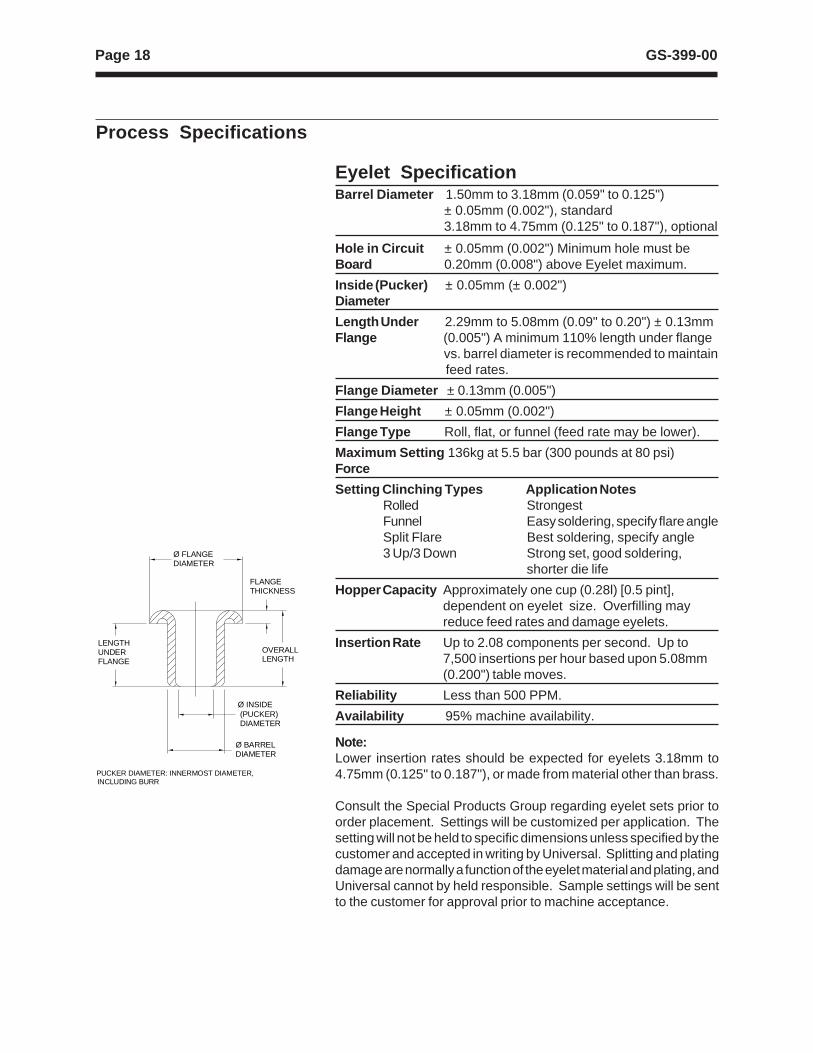
PUCKER DIAMETER: INNERMOST DIAMETER, INCLUDING BURR
LENGTHUNDERFLANGE
OVERALLLENGTH
Ø INSIDE (PUCKER) DIAMETER
Ø FLANGEDIAMETER
Ø BARREL DIAMETER
FLANGETHICKNESS
Note:Lower insertion rates should be expected for eyelets 3.18mm to4.75mm (0.125" to 0.187"), or made from material other than brass.
Consult the Special Products Group regarding eyelet sets prior toorder placement. Settings will be customized per application. Thesetting will not be held to specific dimensions unless specified by thecustomer and accepted in writing by Universal. Splitting and platingdamage are normally a function of the eyelet material and plating, andUniversal cannot by held responsible. Sample settings will be sentto the customer for approval prior to machine acceptance.
Page 19GS-399-00
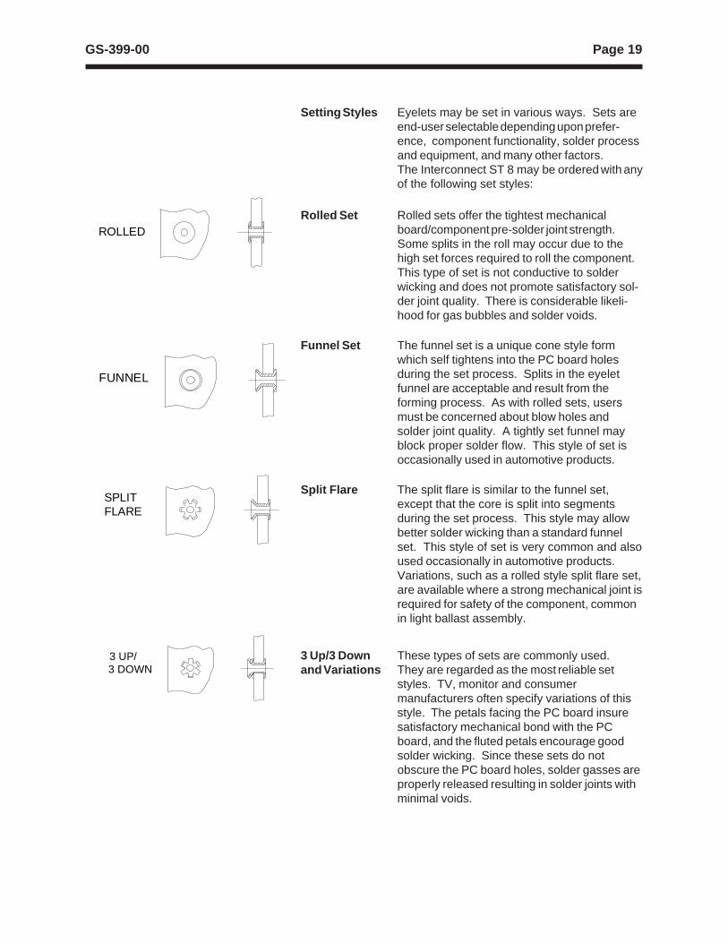
Setting Styles Eyelets may be set in various ways. Sets areend-user selectable depending upon prefer-ence, component functionality, solder processand equipment, and many other factors.The Interconnect ST 8 may be ordered with anyof the following set styles:
Rolled Set Rolled sets offer the tightest mechanicalboard/component pre-solder joint strength.Some splits in the roll may occur due to thehigh set forces required to roll the component.This type of set is not conductive to solderwicking and does not promote satisfactory sol-der joint quality. There is considerable likeli-hood for gas bubbles and solder voids.
Funnel Set The funnel set is a unique cone style formwhich self tightens into the PC board holesduring the set process. Splits in the eyeletfunnel are acceptable and result from theforming process. As with rolled sets, usersmust be concerned about blow holes andsolder joint quality. A tightly set funnel mayblock proper solder flow. This style of set isoccasionally used in automotive products.
Split Flare The split flare is similar to the funnel set,except that the core is split into segmentsduring the set process. This style may allowbetter solder wicking than a standard funnelset. This style of set is very common and alsoused occasionally in automotive products.Variations, such as a rolled style split flare set,are available where a strong mechanical joint isrequired for safety of the component, commonin light ballast assembly.
3 Up/3 Down These types of sets are commonly used.and Variations They are regarded as the most reliable set
styles. TV, monitor and consumermanufacturers often specify variations of thisstyle. The petals facing the PC board insuresatisfactory mechanical bond with the PCboard, and the fluted petals encourage goodsolder wicking. Since these sets do notobscure the PC board holes, solder gasses areproperly released resulting in solder joints withminimal voids.
FUNNEL
SPLITFLARE
3 UP/3 DOWN
ROLLED
Page 20 GS-399-00
Set Angles Set angles may vary depending upon userspecifications and preferences. Angles mayrange from 0° (flat) to 90° (perpendicular).Most sets are specified at inclusiveangles between 60° and 120°, ±10°.
Material Options Eyelets are available in various formats andmaterials. Each of these influence setselections and solder joint consistency.
Unscored Unscored eyelets are solid-formed which do notEyelets have any predefined split lines. These eyelets
are split by the insertion machine’s lower die.The accuracy of the lower dies, machine set-up, and material greatly influence the regularityof these types of splits. Unscored dies are themost common types. The base material isusually brass. Steel eyelets also are usedoccasionally, but do not feed reliably. They areprone to self magnetism.
Scored Eyelets Scored eyelets are prescored to split in a verypredictable fashion. The lower die initiates asplit along these predetermined score lines.This type of eyelet offers the most consistentsets and imparts the least stress and wear onthe lower dies.
Page 21GS-399-00
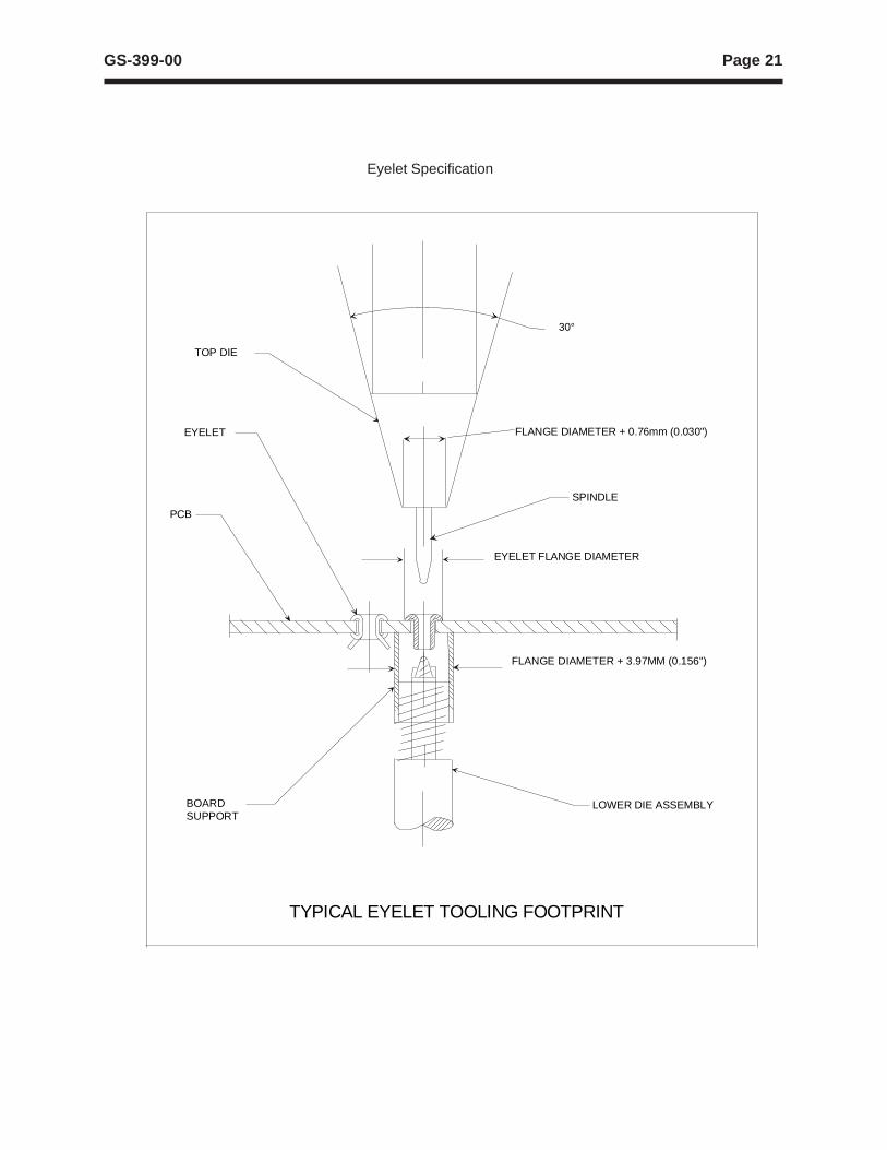
TYPICAL EYELET TOOLING FOOTPRINT
BOARDSUPPORT
EYELET
PCB
LOWER DIE ASSEMBLY
SPINDLE
TOP DIE
FLANGE DIAMETER + 3.97MM (0.156")
30°
FLANGE DIAMETER + 0.76mm (0.030")
EYELET FLANGE DIAMETER
Eyelet Specification
Page 22 GS-399-00
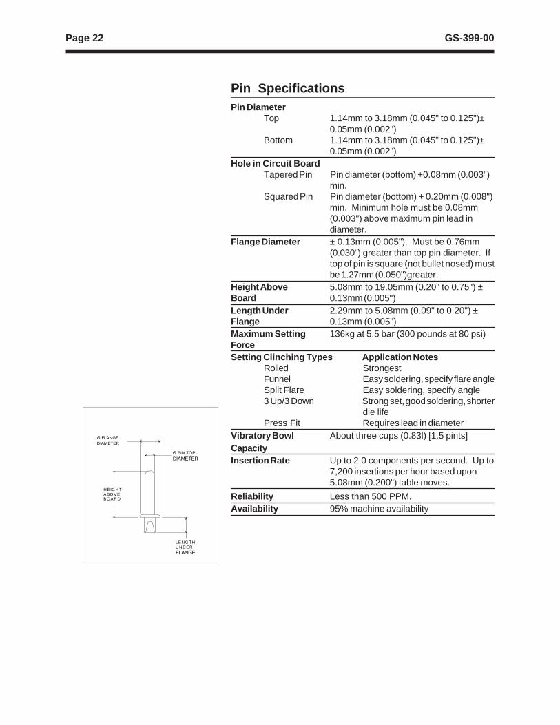
Pin SpecificationsPin Diameter
Top 1.14mm to 3.18mm (0.045" to 0.125")±0.05mm (0.002")
Bottom 1.14mm to 3.18mm (0.045" to 0.125")±0.05mm (0.002")
Hole in Circuit BoardTapered Pin Pin diameter (bottom) +0.08mm (0.003")
min.Squared Pin Pin diameter (bottom) + 0.20mm (0.008")
min. Minimum hole must be 0.08mm(0.003") above maximum pin lead indiameter.
Flange Diameter ± 0.13mm (0.005"). Must be 0.76mm(0.030") greater than top pin diameter. Iftop of pin is square (not bullet nosed) mustbe 1.27mm (0.050")greater.
Height Above 5.08mm to 19.05mm (0.20" to 0.75") ±Board 0.13mm (0.005")Length Under 2.29mm to 5.08mm (0.09" to 0.20") ±Flange 0.13mm (0.005")Maximum Setting 136kg at 5.5 bar (300 pounds at 80 psi)ForceSetting Clinching Types Application Notes
Rolled StrongestFunnel Easy soldering, specify flare angleSplit Flare Easy soldering, specify angle3 Up/3 Down Strong set, good soldering, shorter
die lifePress Fit Requires lead in diameter
Vibratory Bowl About three cups (0.83l) [1.5 pints]CapacityInsertion Rate Up to 2.0 components per second. Up to
7,200 insertions per hour based upon5.08mm (0.200") table moves.
Reliability Less than 500 PPM.Availability 95% machine availability
HEIGH TABO VEBOARD
LENG THUNDERFLANGE
Ø FLANGEDIAMETER
Ø PIN TOP
DIAMETER
Page 23GS-399-00
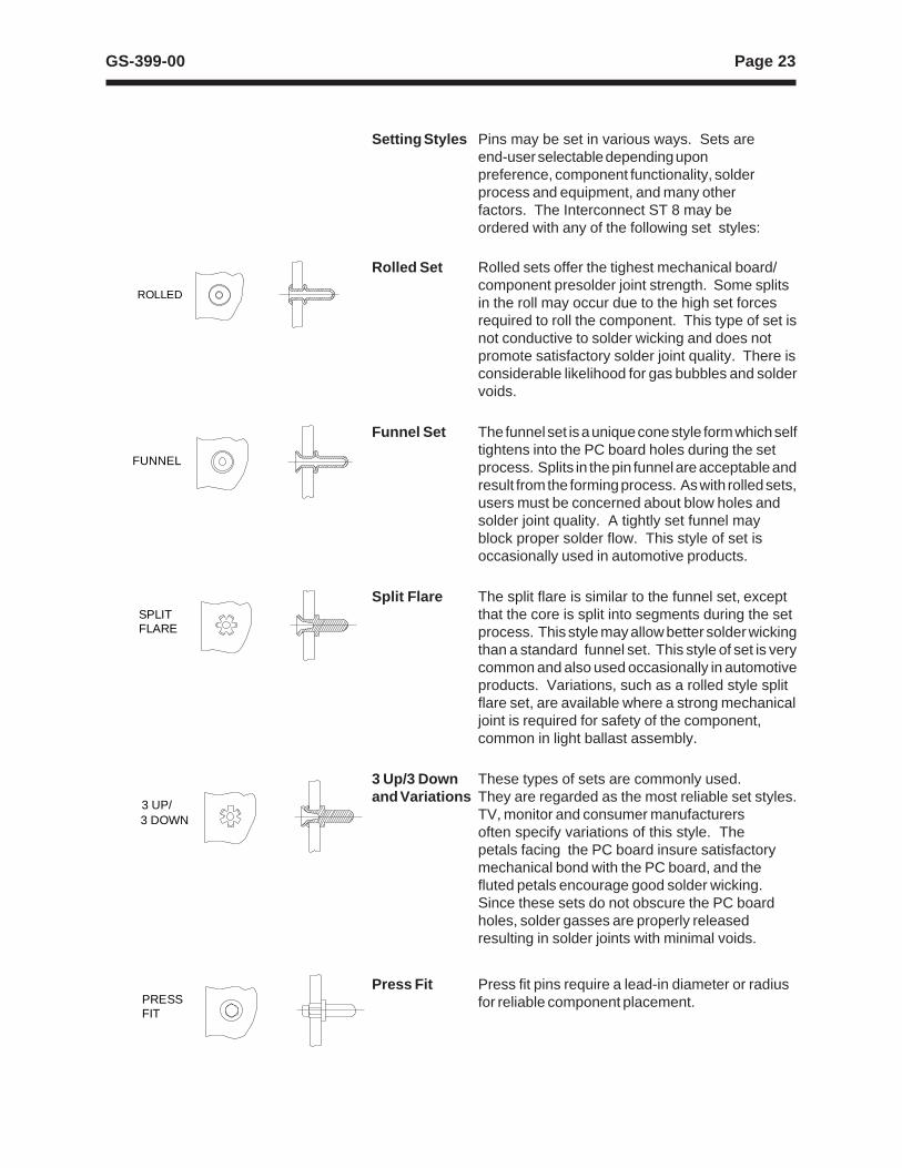
Rolled Set Rolled sets offer the tighest mechanical board/component presolder joint strength. Some splitsin the roll may occur due to the high set forcesrequired to roll the component. This type of set isnot conductive to solder wicking and does notpromote satisfactory solder joint quality. There isconsiderable likelihood for gas bubbles and soldervoids.
Funnel Set The funnel set is a unique cone style form which selftightens into the PC board holes during the setprocess. Splits in the pin funnel are acceptable andresult from the forming process. As with rolled sets,users must be concerned about blow holes andsolder joint quality. A tightly set funnel mayblock proper solder flow. This style of set isoccasionally used in automotive products.
Split Flare The split flare is similar to the funnel set, exceptthat the core is split into segments during the setprocess. This style may allow better solder wickingthan a standard funnel set. This style of set is verycommon and also used occasionally in automotiveproducts. Variations, such as a rolled style splitflare set, are available where a strong mechanicaljoint is required for safety of the component,common in light ballast assembly.
3 Up/3 Down These types of sets are commonly used.and Variations They are regarded as the most reliable set styles.
TV, monitor and consumer manufacturersoften specify variations of this style. Thepetals facing the PC board insure satisfactorymechanical bond with the PC board, and thefluted petals encourage good solder wicking.Since these sets do not obscure the PC boardholes, solder gasses are properly releasedresulting in solder joints with minimal voids.
Press Fit Press fit pins require a lead-in diameter or radiusfor reliable component placement.
ROLLED
FUNNEL
SPLITFLARE
3 UP/3 DOWN
PRESSFIT
Setting Styles Pins may be set in various ways. Sets areend-user selectable depending uponpreference, component functionality, solderprocess and equipment, and many otherfactors. The Interconnect ST 8 may beordered with any of the following set styles:
Page 24 GS-399-00
Notes:Only possible setting if hole in bottom of pin is less than0.76mm (0.030") diameter is crushed type set.
Please consult the Special Products Group regarding eyelet/pin sets prior to order placement. Settings will be customized perapplication.
On parts with seams, the part will naturally split at the seam.
The setting will not be held to specific dimensions unlessspecified by the customer and accepted in writing byUniversal. Splitting and plating damage are normally a functionof the pin material and plating, and Universal cannot be heldresponsible. Sample settings will be sent to the customer forapproval prior to machine acceptance.
Set Angles Set angles may vary depending upon userspecifications and preferences. Angles mayrange from 0° (flat) to 90° (perpendicular). Mostsets are specified at inclusive angles between60° and 120°, ± 10°.
Material Pins are available in various formats andOptions materials. Each of these influence set selections
and solder joint consistency.
Unscored Unscored pins are solid-formed which do notPins have any predefined split lines. Thes pins are
split by the insertion machine’s lower die. Theaccuracy of the lower dies, machine set up, andmaterial greatly influence the regularity of thesetypes of splits. Unscored dies are the mostcommon types. The base material is usuallybrass. Steel pins are used occasionally, but donot feed reliably. They are prone to selfmagnetism.
Rolled Seam Some pins have rolled seams from thePins manufacturing process. These seams may
influence the set consistency.
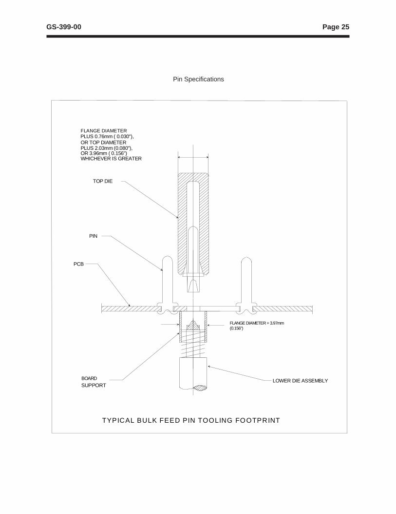
Page 25GS-399-00
TYPICAL BULK FEED PIN TOOLING FOOTPRINT
BOARD
SUPPORT
PCB
LOWER DIE ASSEMBLY
PIN
TOP DIE
PLUS 0.76mm ( 0.030"),FLANGE DIAMETER
OR TOP DIAMETERPLUS 2.03mm (0.080"),OR 3.96mm ( 0.156")WHICHEVER IS GREATER
FLANGE DIAMETER + 3.97mm(0.156")
Pin Specifications
Page 26 GS-399-00
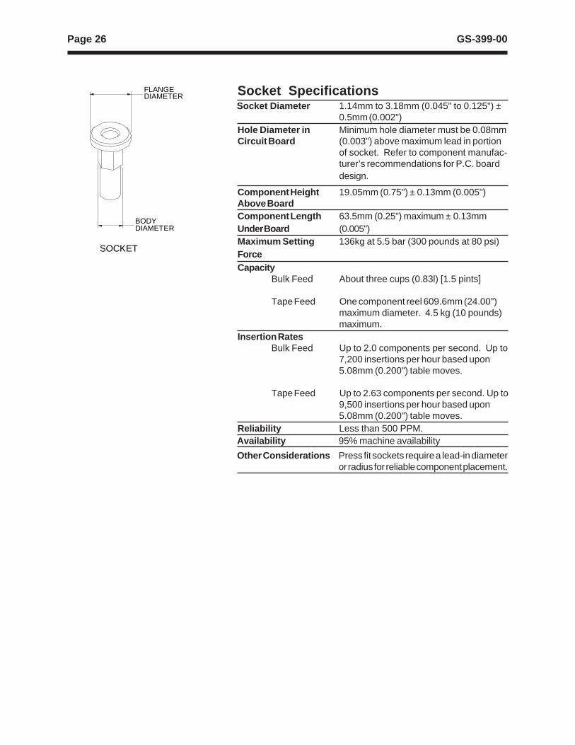
Socket Specifications Socket Diameter 1.14mm to 3.18mm (0.045" to 0.125") ±
0.5mm (0.002")Hole Diameter in Minimum hole diameter must be 0.08mmCircuit Board (0.003") above maximum lead in portion
of socket. Refer to component manufac-turer’s recommendations for P.C. boarddesign.
Component Height 19.05mm (0.75") ± 0.13mm (0.005")Above BoardComponent Length 63.5mm (0.25") maximum ± 0.13mmUnder Board (0.005")Maximum Setting 136kg at 5.5 bar (300 pounds at 80 psi)ForceCapacity
Bulk Feed About three cups (0.83l) [1.5 pints]
Tape Feed One component reel 609.6mm (24.00")maximum diameter. 4.5 kg (10 pounds)maximum.
Insertion RatesBulk Feed Up to 2.0 components per second. Up to
7,200 insertions per hour based upon5.08mm (0.200") table moves.
Tape Feed Up to 2.63 components per second. Up to9,500 insertions per hour based upon5.08mm (0.200") table moves.
Reliability Less than 500 PPM.Availability 95% machine availability
Other Considerations Press fit sockets require a lead-in diameteror radius for reliable component placement.
SOCKET
BODYDIAMETER
FLANGEDIAMETER
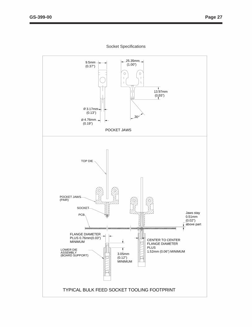
Page 27GS-399-00
TYPICAL BULK FEED SOCKET TOOLING FOOTPRINT
POCKET JAWS(PAIR)
LOWER DIEASSEMBLY(BOARD SUPPORT)
PCB
SOCKET
POCKET JAWS
TOP DIE
13.97mm (0.55")
3.05mm(0.12")MINIMUM
FLANGE DIAMETERPLUS 0.76mm(0.03")MINIMUM
9.5mm(0.37")
3.17mm(0.13")
Ø 4.76mm (0.19")
25.35mm (1.00")
Jaws stay0.51mm(0.02")above part
Ø
30°
CENTER TO CENTERFLANGE DIAMETERPLUS1.52mm (0.06") MINIMUM
Socket Specifications
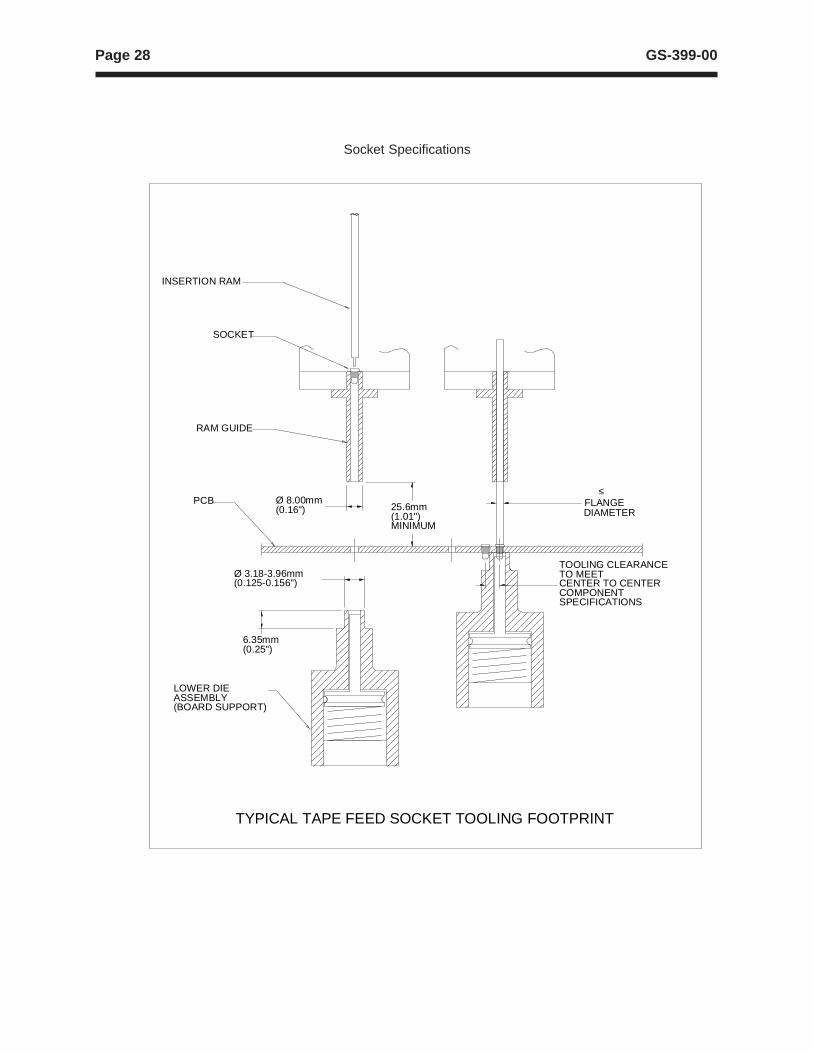
Page 28 GS-399-00
TYPICAL TAPE FEED SOCKET TOOLING FOOTPRINT
INSERTION RAM
SOCKET
RAM GUIDE
PCB
LOWER DIEASSEMBLY(BOARD SUPPORT)
6.35mm(0.25")
Ø 3.18-3.96mm(0.125-0.156")
Ø 8.00mm(0.16")
< FLANGEDIAMETER
25.6mm(1.01")MINIMUM
TOOLING CLEARANCETO MEETCENTER TO CENTERCOMPONENTSPECIFICATIONS
_
Socket Specifications
Page 29GS-399-00
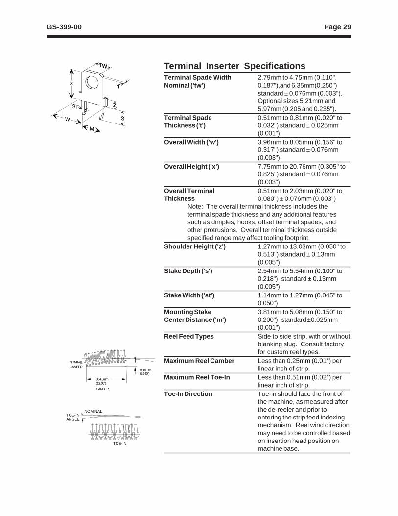
Terminal Inserter SpecificationsTerminal Spade Width 2.79mm to 4.75mm (0.110",Nominal ('tw') 0.187"),and 6.35mm(0.250")
standard ± 0.076mm (0.003").Optional sizes 5.21mm and5.97mm (0.205 and 0.235").
Terminal Spade 0.51mm to 0.81mm (0.020" toThickness ('t') 0.032") standard ± 0.025mm
(0.001")Overall Width ('w') 3.96mm to 8.05mm (0.156" to
0.317") standard ± 0.076mm(0.003")
Overall Height ('x') 7.75mm to 20.76mm (0.305" to0.825") standard ± 0.076mm(0.003")
Overall Terminal 0.51mm to 2.03mm (0.020" toThickness 0.080") ± 0.076mm (0.003")
Note: The overall terminal thickness includes theterminal spade thickness and any additional featuressuch as dimples, hooks, offset terminal spades, andother protrusions. Overall terminal thickness outsidespecified range may affect tooling footprint.
Shoulder Height ('z') 1.27mm to 13.03mm (0.050" to0.513") standard ± 0.13mm(0.005")
Stake Depth ('s') 2.54mm to 5.54mm (0.100" to0.218") standard ± 0.13mm(0.005")
Stake Width ('st') 1.14mm to 1.27mm (0.045" to0.050")
Mounting Stake 3.81mm to 5.08mm (0.150" toCenter Distance ('m') 0.200") standard ±0.025mm
(0.001")Reel Feed Types Side to side strip, with or without
blanking slug. Consult factoryfor custom reel types.
Maximum Reel Camber Less than 0.25mm (0.01") perlinear inch of strip.
Maximum Reel Toe-In Less than 0.51mm (0.02") perlinear inch of strip.
Toe-In Direction Toe-in should face the front ofthe machine, as measured afterthe de-reeler and prior toentering the strip feed indexingmechanism. Reel wind directionmay need to be controlled basedon insertion head position onmachine base.
304.8mm(12.00”)
6.10mm.(0.240”)
CAMBER
NOMINALCAMBER
TOE-INANGLE
TOE-IN
NOMINAL
Page 30 GS-399-00
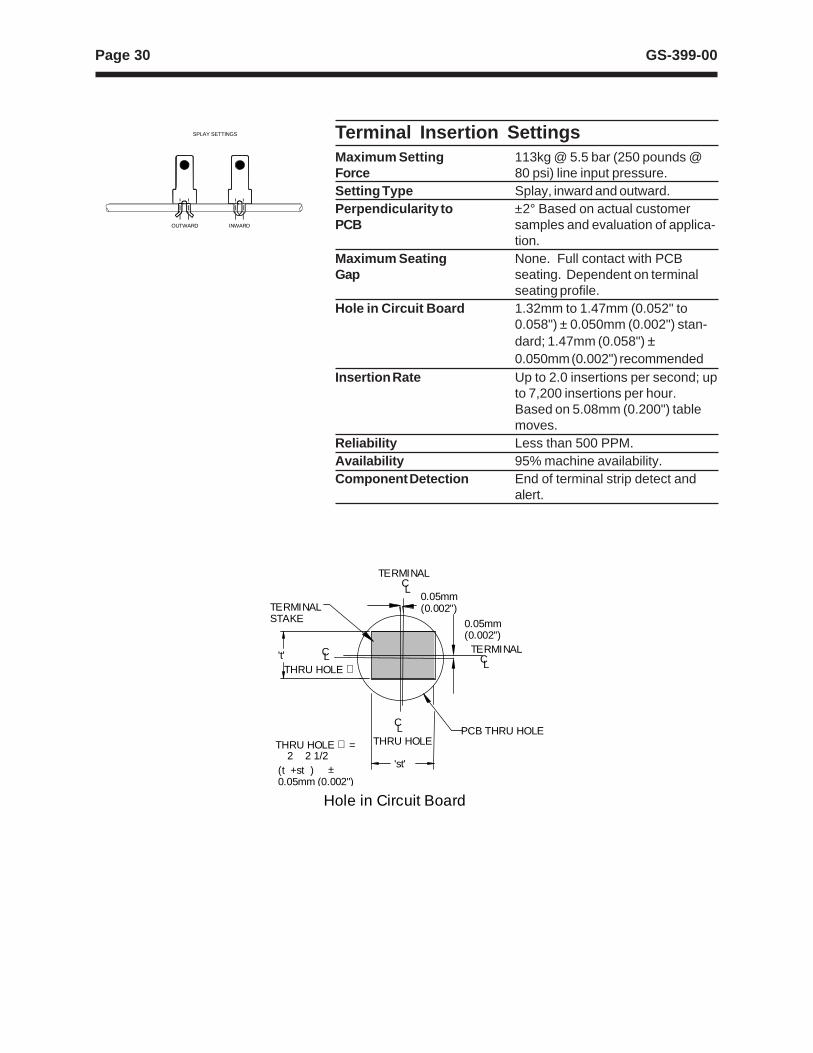
Terminal Insertion SettingsMaximum Setting 113kg @ 5.5 bar (250 pounds @Force 80 psi) line input pressure.Setting Type Splay, inward and outward.Perpendicularity to ±2° Based on actual customerPCB samples and evaluation of applica-
tion.Maximum Seating None. Full contact with PCBGap seating. Dependent on terminal
seating profile.Hole in Circuit Board 1.32mm to 1.47mm (0.052" to
0.058") ± 0.050mm (0.002") stan-dard; 1.47mm (0.058") ±0.050mm (0.002") recommended
Insertion Rate Up to 2.0 insertions per second; upto 7,200 insertions per hour.Based on 5.08mm (0.200") tablemoves.
Reliability Less than 500 PPM.Availability 95% machine availability.Component Detection End of terminal strip detect and
alert.
OUTWARD INWARD
SPLAY SETTINGS
THRU HOLE
TERMINAL
(t +st ) ±0.05mm (0.002")
THRU HOLE ∅ =
THRU HOLE ∅
2 2 1/2
TERMINALSTAKE
't' CL
PCB THRU HOLEL
'st'
C
TERMINAL
LC
LC
0.05mm(0.002")
0.05mm(0.002")
Hole in Circuit Board
Page 31GS-399-00
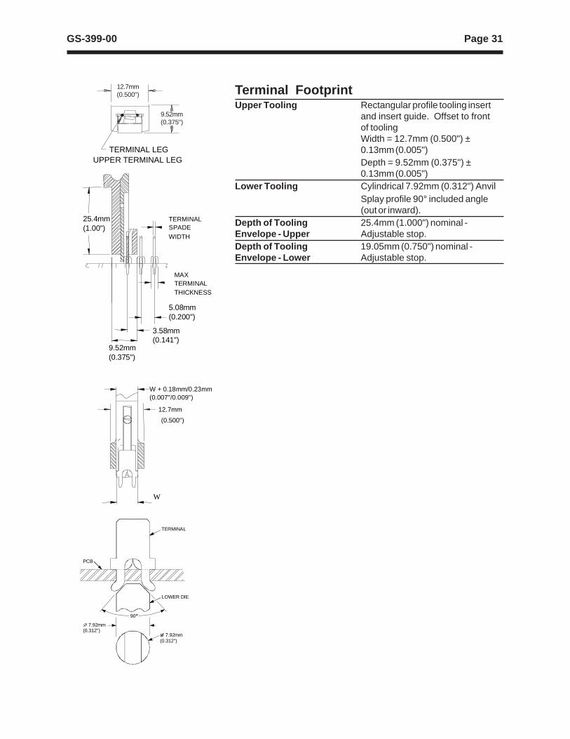
Terminal FootprintUpper Tooling Rectangular profile tooling insert
and insert guide. Offset to frontof toolingWidth = 12.7mm (0.500") ±0.13mm (0.005")Depth = 9.52mm (0.375") ±0.13mm (0.005")
Lower Tooling Cylindrical 7.92mm (0.312") AnvilSplay profile 90° included angle(out or inward).
Depth of Tooling 25.4mm (1.000") nominal -Envelope - Upper Adjustable stop.Depth of Tooling 19.05mm (0.750") nominal -Envelope - Lower Adjustable stop.
TERMINAL LEGUPPER TERMINAL LEG
12.7mm(0.500")
9.52mm(0.375")
9.52mm(0.375")
25.4mm(1.00")
TERMINALSPADEWIDTH
MAXTERMINALTHICKNESS
5.08mm(0.200")
3.58mm(0.141")
W + 0.18mm/0.23mm(0.007"/0.009")
12.7mm
(0.500")
W
90
7.92mm(0.312")
7.92mm(0.312")
TERMINAL
LOWER DIE
PCB
Page 32 GS-399-00
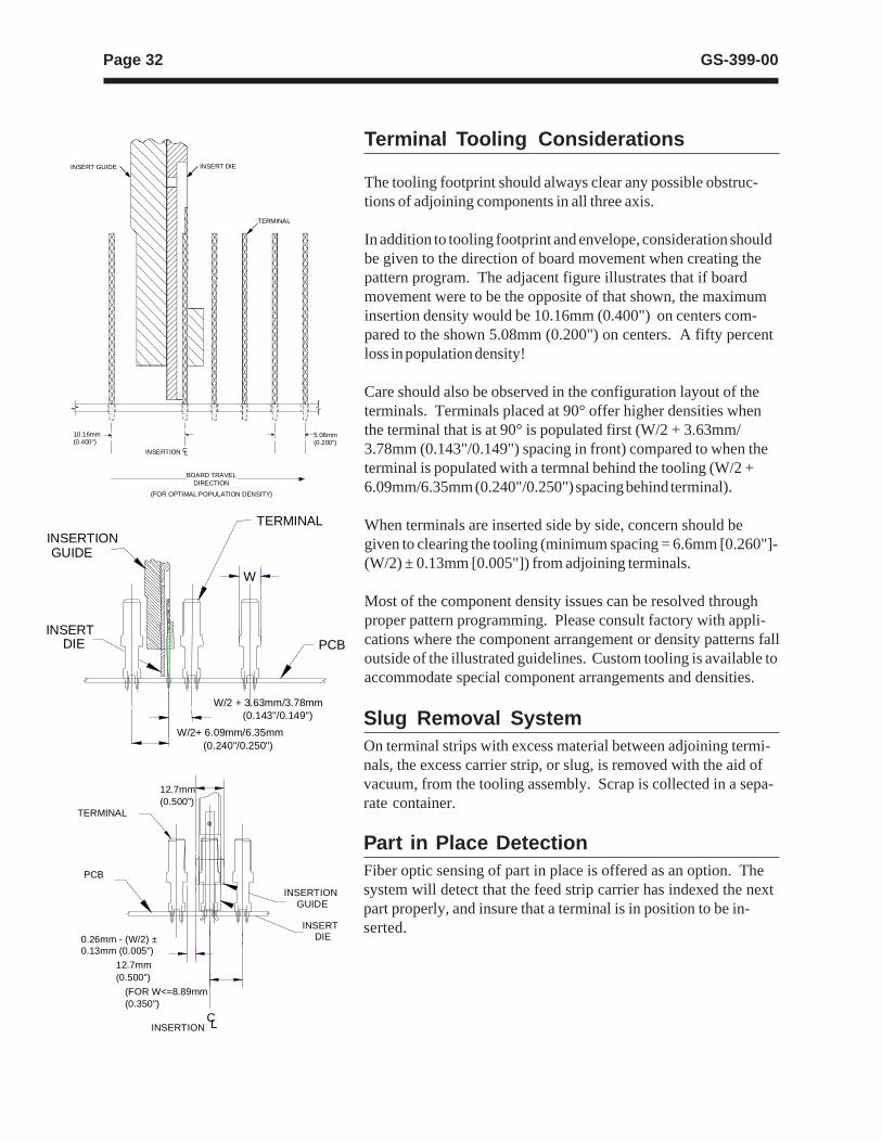
Terminal Tooling Considerations
The tooling footprint should always clear any possible obstruc-tions of adjoining components in all three axis.
In addition to tooling footprint and envelope, consideration shouldbe given to the direction of board movement when creating thepattern program. The adjacent figure illustrates that if boardmovement were to be the opposite of that shown, the maximuminsertion density would be 10.16mm (0.400") on centers com-pared to the shown 5.08mm (0.200") on centers. A fifty percentloss in population density!
Care should also be observed in the configuration layout of theterminals. Terminals placed at 90° offer higher densities whenthe terminal that is at 90° is populated first (W/2 + 3.63mm/3.78mm (0.143"/0.149") spacing in front) compared to when theterminal is populated with a termnal behind the tooling (W/2 +6.09mm/6.35mm (0.240"/0.250") spacing behind terminal).
When terminals are inserted side by side, concern should begiven to clearing the tooling (minimum spacing = 6.6mm [0.260"]-(W/2) ± 0.13mm [0.005"]) from adjoining terminals.
Most of the component density issues can be resolved throughproper pattern programming. Please consult factory with appli-cations where the component arrangement or density patterns falloutside of the illustrated guidelines. Custom tooling is available toaccommodate special component arrangements and densities.
Slug Removal SystemOn terminal strips with excess material between adjoining termi-nals, the excess carrier strip, or slug, is removed with the aid ofvacuum, from the tooling assembly. Scrap is collected in a sepa-rate container.
Part in Place DetectionFiber optic sensing of part in place is offered as an option. Thesystem will detect that the feed strip carrier has indexed the nextpart properly, and insure that a terminal is in position to be in-serted.
W/2 + 3.63mm/3.78mm (0.143"/0.149")
W/2+ 6.09mm/6.35mm (0.240"/0.250")
W
INSERTIONTERMINAL
PCBINSERT
DIE
GUIDE
0.26mm - (W/2) ±0.13mm (0.005")
12.7mm(0.500”)
12.7mm(0.500")
INSERTION
(FOR W<=8.89mm(0.350")
CL
TERMINAL
PCB
INSERTION
INSERT
GUIDE
DIE
TERMINAL
INSERT GUIDE INSERT DIE
10.16mm(0.400")
INSERTION CL
5.08mm(0.200")
BOARD TRAVELDIRECTION
(FOR OPTIMAL POPULATION DENSITY)
Page 33GS-399-00
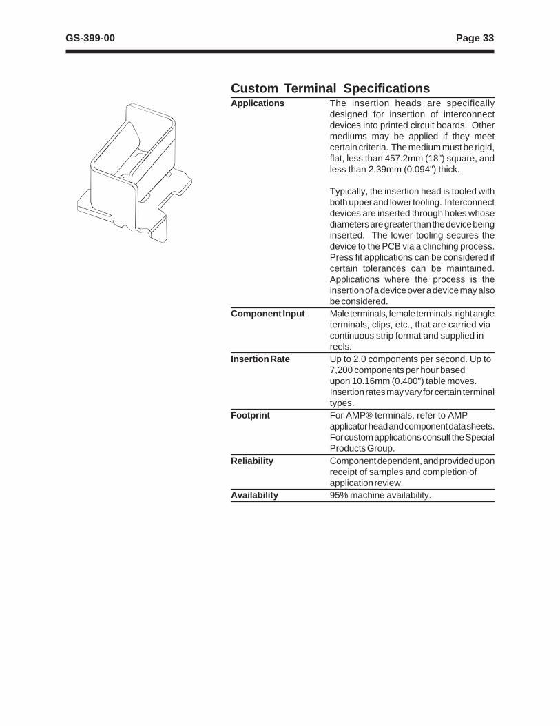
Custom Terminal SpecificationsApplications The insertion heads are specifically
designed for insertion of interconnectdevices into printed circuit boards. Othermediums may be applied if they meetcertain criteria. The medium must be rigid,flat, less than 457.2mm (18") square, andless than 2.39mm (0.094") thick.
Typically, the insertion head is tooled withboth upper and lower tooling. Interconnectdevices are inserted through holes whosediameters are greater than the device beinginserted. The lower tooling secures thedevice to the PCB via a clinching process.Press fit applications can be considered ifcertain tolerances can be maintained.Applications where the process is theinsertion of a device over a device may alsobe considered.
Component Input Male terminals, female terminals, right angleterminals, clips, etc., that are carried viacontinuous strip format and supplied inreels.
Insertion Rate Up to 2.0 components per second. Up to7,200 components per hour basedupon 10.16mm (0.400") table moves.Insertion rates may vary for certain terminaltypes.
Footprint For AMP® terminals, refer to AMPapplicator head and component data sheets.For custom applications consult the SpecialProducts Group.
Reliability Component dependent, and provided uponreceipt of samples and completion ofapplication review.
Availability 95% machine availability.
Page 34 GS-399-00
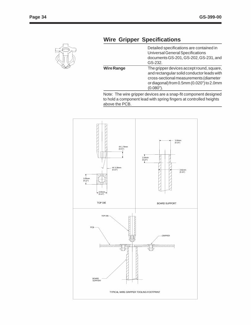
Wire Gripper SpecificationsDetailed specifications are contained inUniversal General Specificationsdocuments GS-201, GS-202, GS-231, andGS-232.
Wire Range The gripper devices accept round, square,and rectangular solid conductor leads withcross-sectional measurements (diameteror diagonal) from 0.5mm (0.020") to 2.0mm(0.080").
Note: The wire gripper devices are a snap-fit component designedto hold a component lead with spring fingers at controlled heightsabove the PCB.
4X 1.78mm(0.07")
4X 3.30mm(0.13")
3.05mm(0.12")
3.05mm(0.12")
TOP DIE BOARD SUPPORT
3.81mm(0.15")
3.30mm(0.13")
2.54mm(0.10")
TOP DIE
GRIPPER
PCB
BOARDSUPPORT
TYPICAL WIRE GRIPPER TOOLING FOOTPRINT
Page 35GS-399-00
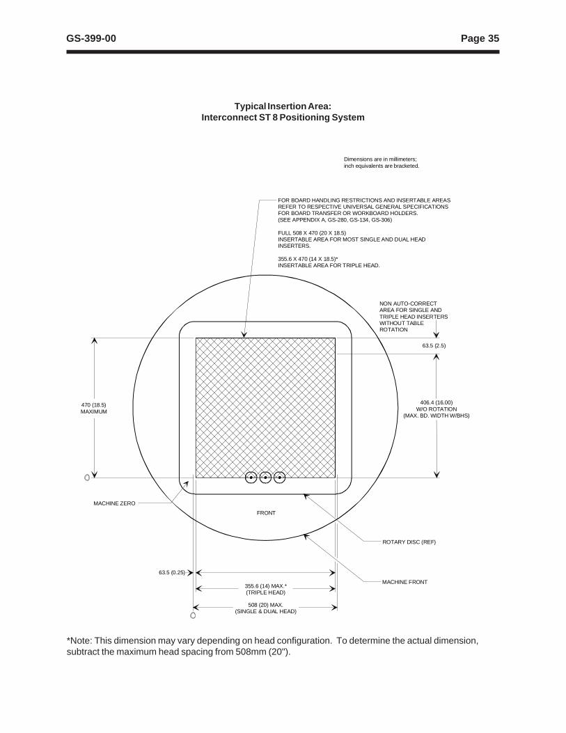
Typical Insertion Area:Interconnect ST 8 Positioning System
FRONT
470 (18.5) MAXIMUM
406.4 (16.00)W/O ROTATION
(MAX. BD. WIDTH W/BHS)
63.5 (2.5)
NON AUTO-CORRECTAREA FOR SINGLE ANDTRIPLE HEAD INSERTERSWITHOUT TABLEROTATION
FOR BOARD HANDLING RESTRICTIONS AND INSERTABLE AREASREFER TO RESPECTIVE UNIVERSAL GENERAL SPECIFICATIONSFOR BOARD TRANSFER OR WORKBOARD HOLDERS.(SEE APPENDIX A, GS-280, GS-134, GS-306)
FULL 508 X 470 (20 X 18.5)INSERTABLE AREA FOR MOST SINGLE AND DUAL HEADINSERTERS.
355.6 X 470 (14 X 18.5)*INSERTABLE AREA FOR TRIPLE HEAD.
508 (20) MAX.(SINGLE & DUAL HEAD)
355.6 (14) MAX.*(TRIPLE HEAD)
63.5 (0.25)
ROTARY DISC (REF)
MACHINE FRONT
Dimensions are in millimeters; inch equivalents are bracketed.
MACHINE ZERO
*Note: This dimension may vary depending on head configuration. To determine the actual dimension,subtract the maximum head spacing from 508mm (20").
Page 36 GS-399-00
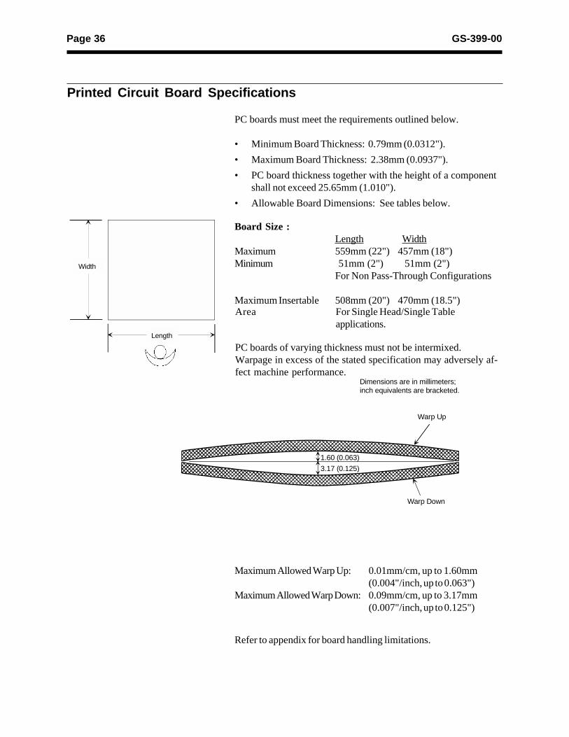
Printed Circuit Board Specifications
PC boards must meet the requirements outlined below.
• Minimum Board Thickness: 0.79mm (0.0312").
• Maximum Board Thickness: 2.38mm (0.0937").
• PC board thickness together with the height of a componentshall not exceed 25.65mm (1.010").
• Allowable Board Dimensions: See tables below.
Board Size :Length Width
Maximum 559mm (22") 457mm (18")Minimum 51mm (2") 51mm (2")
For Non Pass-Through Configurations
Maximum Insertable 508mm (20") 470mm (18.5")
Length
Width
Area For Single Head/Single Tableapplications.
PC boards of varying thickness must not be intermixed.Warpage in excess of the stated specification may adversely af-fect machine performance.
Maximum Allowed Warp Up: 0.01mm/cm, up to 1.60mm(0.004"/inch, up to 0.063")
Maximum Allowed Warp Down: 0.09mm/cm, up to 3.17mm(0.007"/inch, up to 0.125")
Refer to appendix for board handling limitations.
Warp Down
Warp Up
��������������������������������
��������������������������������1.60 (0.063)
3.17 (0.125)
Dimensions are in millimeters;inch equivalents are bracketed.
Page 37GS-399-00
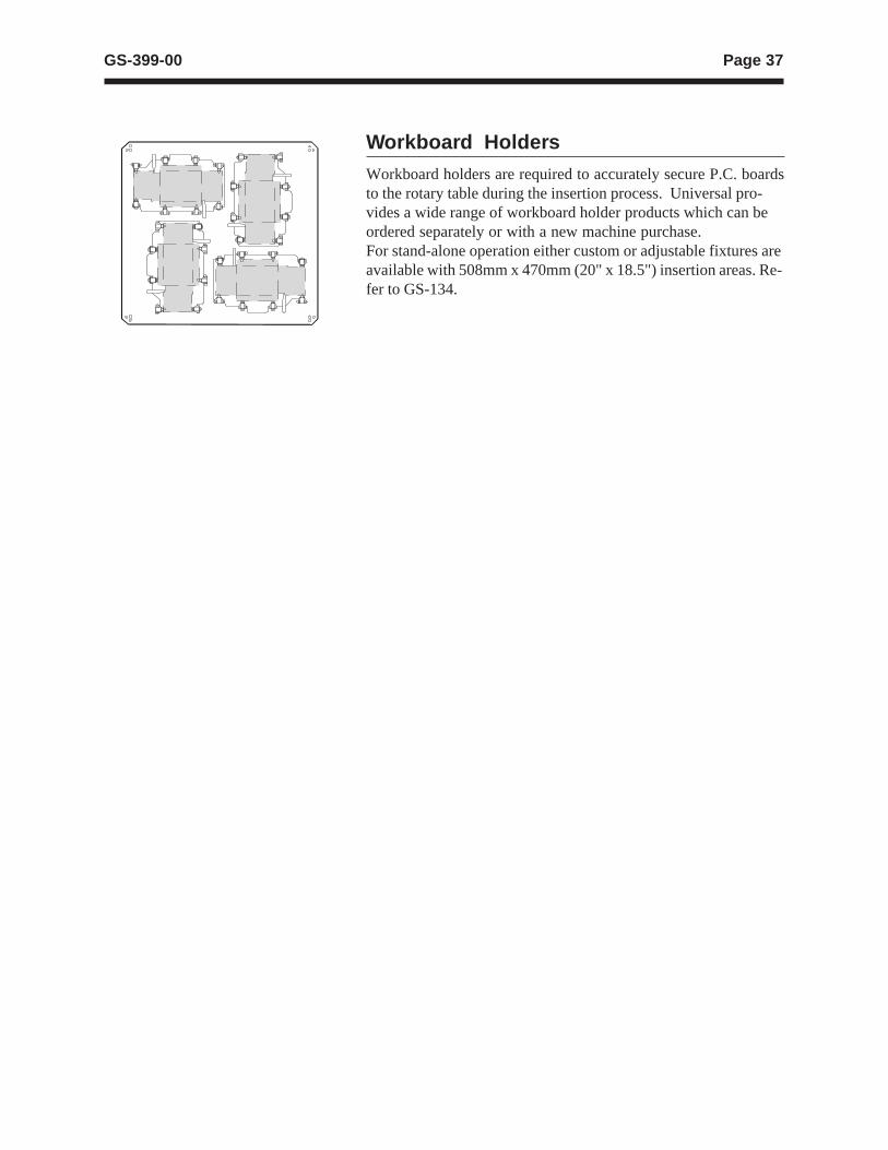
Workboard Holders
Workboard holders are required to accurately secure P.C. boardsto the rotary table during the insertion process. Universal pro-vides a wide range of workboard holder products which can beordered separately or with a new machine purchase.For stand-alone operation either custom or adjustable fixtures areavailable with 508mm x 470mm (20" x 18.5") insertion areas. Re-fer to GS-134.
Page 38 GS-399-00
Special Products Considerations
ReliabilityLess than 500 PPM. Components, PC boards, or othercontrollable factors varying from Universal specification willaffect PPM rates. Quoted rates are subject to review ofcustomer-supplied materials and documentation.
Component Evaluation and Supply
Due to the many varieties and sizes of interconnect components,Universal does not carry an inventory of these components. Atthe time of order placement, submit the quantities of materialsindicated on the quotation or terms and conditions document.These will be used for tooling design, system set up, testing andacceptance.
Taped or strip-fed reeled components should be reeled in a singlecontinuous strip without splices.
Custom Configuration
All interconnect inserters may be custom configured to match thespecific tolerances and dimensions of the customer-suppliedmaterials. To this point, it is important that samples and theircorresponding dimensional drawings are submitted with machineorders. Tooling will be manufatured to accommodate thedocumented dimensions.
Note: It is important to recognize that it is not uncommon forcomponent dimensions to vary greatly from batch to batch andvendor to vendor (especially for eyelets). This may affectmachine performance. In some cases it may be necessary tochange machine tooling to accommodate these variations. Thesemodifications will be quoted upon request.
CE Compliance
Most applications equipped with internal Board Handling System(BHS) are CE-compliant. Please consult your Universal salesengineer for details.

Page 39GS-399-00
Supporting Documents
GS-055 Indexing ROT Tables, Series 6100GS-061 Lead Tape Reel Packaging of Axial
Components, Series 2500GS-072 Satellite Control® Systems, Series 8000GS-112 Board Error CorrectionGS-134 Workboard Holders, Series 6810GS-306 Adjustable Workboard Holders, Stand Alone
and Dual Head, Series 6810GS-319 Pattern Programming Utility (PPU), Model
86721GS-354-01 Through Hole Design GuidelinesEIA RS-296-E Lead Taping of Components in Axial
Configuration for Automatic Insertion
Page 40 GS-399-00
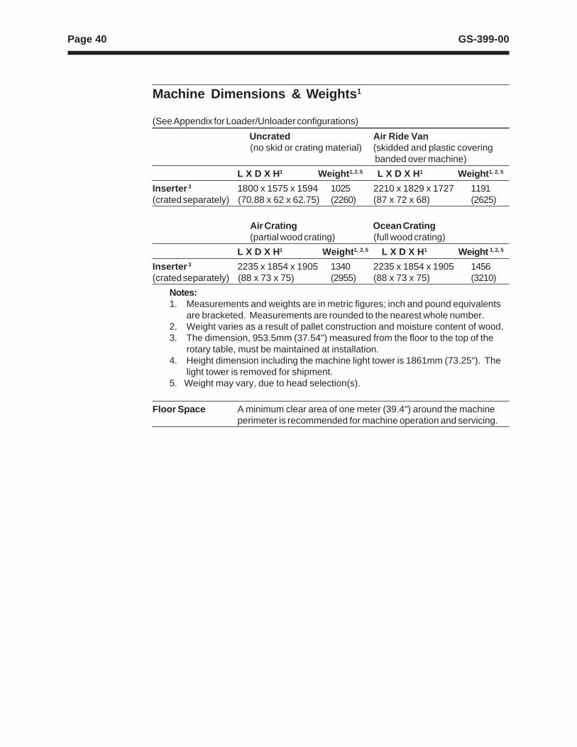
Machine Dimensions & Weights 1
(See Appendix for Loader/Unloader configurations)
Uncrated Air Ride Van(no skid or crating material) (skidded and plastic covering
banded over machine)
L X D X H1 Weight 1, 2, 5 L X D X H1 Weight 1, 2, 5
Inserter 3 1800 x 1575 x 1594 1025 2210 x 1829 x 1727 1191(crated separately) (70.88 x 62 x 62.75) (2260) (87 x 72 x 68) (2625)
Air Crating Ocean Crating(partial wood crating) (full wood crating)
L X D X H1 Weight 1, 2, 5 L X D X H1 Weight 1, 2, 5
Inserter 3 2235 x 1854 x 1905 1340 2235 x 1854 x 1905 1456(crated separately) (88 x 73 x 75) (2955) (88 x 73 x 75) (3210)
Notes:1. Measurements and weights are in metric figures; inch and pound equivalents
are bracketed. Measurements are rounded to the nearest whole number.2. Weight varies as a result of pallet construction and moisture content of wood.3. The dimension, 953.5mm (37.54") measured from the floor to the top of the
rotary table, must be maintained at installation.4. Height dimension including the machine light tower is 1861mm (73.25"). The
light tower is removed for shipment.5. Weight may vary, due to head selection(s).
Floor Space A minimum clear area of one meter (39.4") around the machineperimeter is recommended for machine operation and servicing.
Page 41GS-399-00
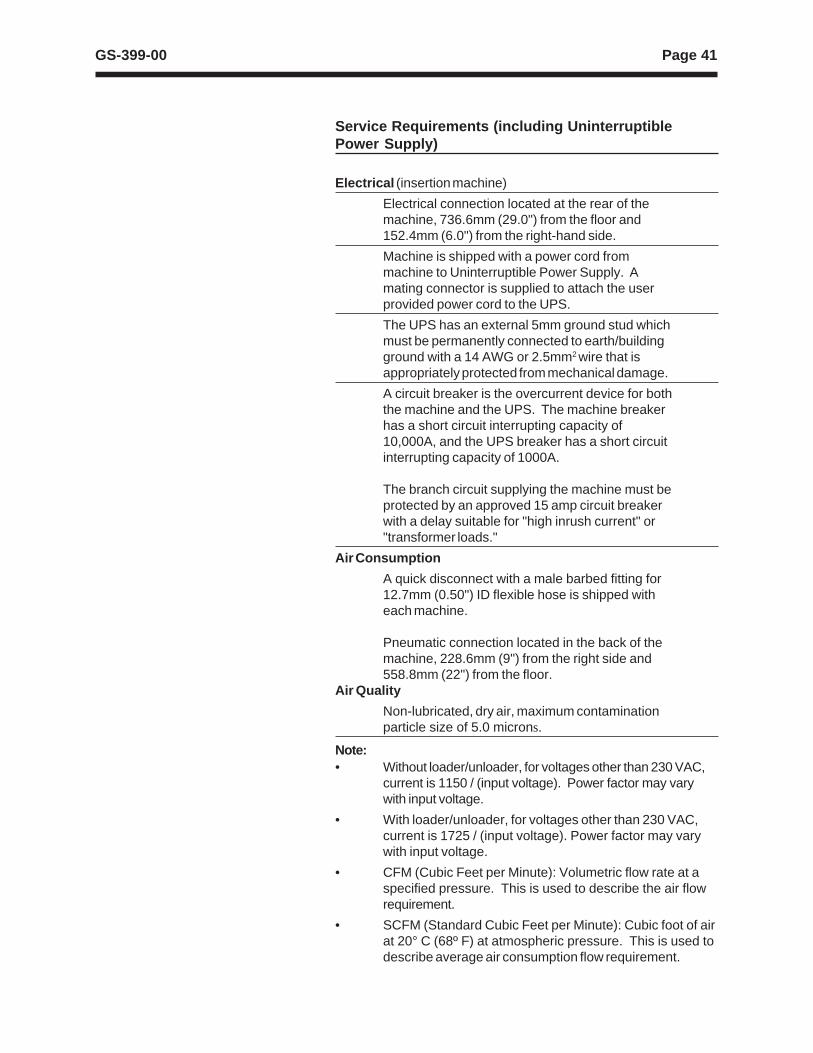
Service Requirements (including UninterruptiblePower Supply)
Electrical (insertion machine)
Electrical connection located at the rear of themachine, 736.6mm (29.0") from the floor and152.4mm (6.0") from the right-hand side.
Machine is shipped with a power cord frommachine to Uninterruptible Power Supply. Amating connector is supplied to attach the userprovided power cord to the UPS.
The UPS has an external 5mm ground stud whichmust be permanently connected to earth/buildingground with a 14 AWG or 2.5mm2 wire that isappropriately protected from mechanical damage.
A circuit breaker is the overcurrent device for boththe machine and the UPS. The machine breakerhas a short circuit interrupting capacity of10,000A, and the UPS breaker has a short circuitinterrupting capacity of 1000A.
The branch circuit supplying the machine must beprotected by an approved 15 amp circuit breakerwith a delay suitable for "high inrush current" or"transformer loads."
Air Consumption
A quick disconnect with a male barbed fitting for12.7mm (0.50") ID flexible hose is shipped witheach machine.
Pneumatic connection located in the back of themachine, 228.6mm (9") from the right side and558.8mm (22") from the floor.
Air Quality
Non-lubricated, dry air, maximum contaminationparticle size of 5.0 microns.
Note:• Without loader/unloader, for voltages other than 230 VAC,
current is 1150 / (input voltage). Power factor may varywith input voltage.
• With loader/unloader, for voltages other than 230 VAC,current is 1725 / (input voltage). Power factor may varywith input voltage.
• CFM (Cubic Feet per Minute): Volumetric flow rate at aspecified pressure. This is used to describe the air flowrequirement.
• SCFM (Standard Cubic Feet per Minute): Cubic foot of airat 20° C (68º F) at atmospheric pressure. This is used todescribe average air consumption flow requirement.
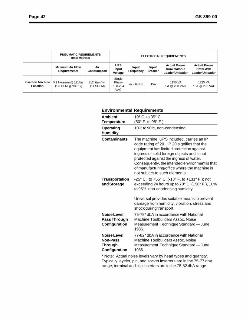
Page 42 GS-399-00
Environmental RequirementsAmbient 10° C. to 35° C.Temperature (50° F. to 95° F.)
Operating 10% to 90%, non-condensingHumidity
Contaminants The machine, UPS included, carries an IPcode rating of 20. IP 20 signifies that theequipment has limited protection againstingress of solid foreign objects and is notprotected against the ingress of water.Consequently, the intended environment is thatof manufacturing/office where the machine isnot subject to such elements.
Transportation -25° C. to +55° C. (-13° F. to +131° F.); notand Storage exceeding 24 hours up to 70° C. (158° F.), 10%
to 95%, non-condensing humidity.
Universal provides suitable means to preventdamage from humidity, vibration, stress andshock during transport.
Noise Level, 75-78* dbA in accordance with NationalPass Through Machine Toolbuilders Assoc. NoiseConfiguration Measurement Technique Standard — June
1986.
Noise Level, 77-82* dbA in accordance with NationalNon-Pass Machine Toolbuilders Assoc. NoiseThrough Measurement Technique Standard — JuneConfiguration 1986.
* Note: Actual noise levels vary by head types and quantity.Typically, eyelet, pin, and socket inserters are in the 75-77 dbArange; terminal and clip inserters are in the 78-82 dbA range.
PNEUMATIC REUIREMENTS(Base Machine)
ELECTRICAL REQUIREMENTS
Minimum Air FlowRequirements
AirConsumption
UPSInput
Voltage
InputFrequency
InputBreaker
Actual PowerDraw Without
Loader/Unloader
Actual PowerDraw With
Loader/Unloader
Insertion MachineLocation
5.2 liters/min @ 6.21 bar (1.8 CFM @ 90 PSI)
312 liters/min(11 SCFM)
SinglePhase
180-264VAC
47 - 63 Hz 15A1150 VA
5A @ 230 VAC1725 VA
7.5A @ 230 VAC

A - 43GS-399-00, Appendix: Automatic Board Handling Systems
Index
Appendix: Automatic Board Handling Systems
Introduction .......................................................................................................... A-44Technical Specifications for Internal Board Handling System (BHS) ............... A-46Dimensions with BHS .......................................................................................... A-48Technical Specifications for Loader/Unloader:
Elevator/Buffer Configuration ....................................................................... A-49Universal Magazine Specifications ............................................................... A-51Magazine-to-Magazine Configuration, with Long Buffer ............................. A-52Magazine-to-Magazine Configuration, with Short Buffer ............................. A-53
Technical Specifications for Loader/Unloader:Vacuum Bare Board-to-Magazine Configuration ......................................... A-54Vacuum Bare Board-to-Magazine Configuration, with 22" Conveyor and LongBuffer .............................................................................................................. A-55Vacuum Bare Board-to-Magazine Configuration, with 22" Conveyor and ShortBuffer .............................................................................................................. A-56
Technical Specifications for Loader/Unloader:Destacker / Conveyor-to-Magazine Configuration ........................................ A-57Destacker / Conveyor-to-Magazine Configuration,with Long Buffer ............................................................................................ A-58Destacker / Conveyor-to-Magazine Configuration,with Short Buffer ............................................................................................ A-59
Installation Considerations: Loader/Unloader .................................................... A-60Service Requirements .......................................................................................... A-61
A - 44 GS-399-00, Appendix: Automatic Board Handling Systems
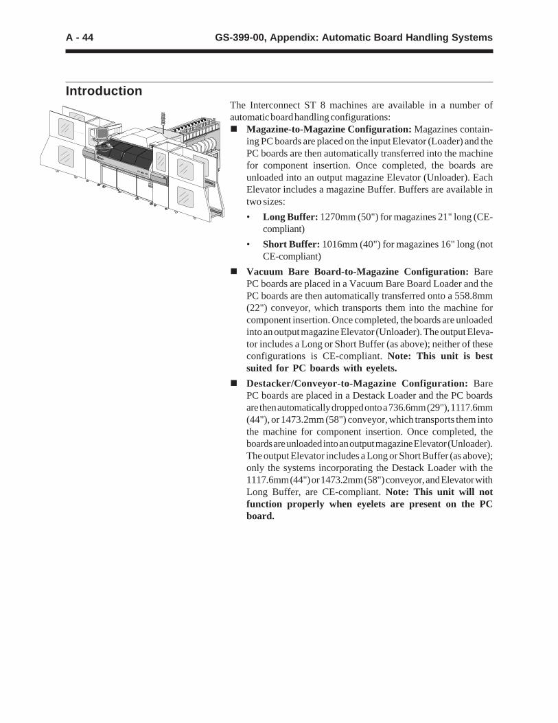
IntroductionThe Interconnect ST 8 machines are available in a number ofautomatic board handling configurations:n Magazine-to-Magazine Configuration: Magazines contain-
ing PC boards are placed on the input Elevator (Loader) and thePC boards are then automatically transferred into the machinefor component insertion. Once completed, the boards areunloaded into an output magazine Elevator (Unloader). EachElevator includes a magazine Buffer. Buffers are available intwo sizes:
• Long Buffer: 1270mm (50") for magazines 21" long (CE-compliant)
• Short Buffer: 1016mm (40") for magazines 16" long (notCE-compliant)
n Vacuum Bare Board-to-Magazine Configuration: BarePC boards are placed in a Vacuum Bare Board Loader and thePC boards are then automatically transferred onto a 558.8mm(22") conveyor, which transports them into the machine forcomponent insertion. Once completed, the boards are unloadedinto an output magazine Elevator (Unloader). The output Eleva-tor includes a Long or Short Buffer (as above); neither of theseconfigurations is CE-compliant. Note: This unit is bestsuited for PC boards with eyelets.
n Destacker/Conveyor-to-Magazine Configuration: BarePC boards are placed in a Destack Loader and the PC boardsare then automatically dropped onto a 736.6mm (29"), 1117.6mm(44"), or 1473.2mm (58") conveyor, which transports them intothe machine for component insertion. Once completed, theboards are unloaded into an output magazine Elevator (Unloader).The output Elevator includes a Long or Short Buffer (as above);only the systems incorporating the Destack Loader with the1117.6mm (44") or 1473.2mm (58") conveyor, and Elevator withLong Buffer, are CE-compliant. Note: This unit will notfunction properly when eyelets are present on the PCboard.
A - 45GS-399-00, Appendix: Automatic Board Handling Systems
n Magazine- OR Destacker/Conveyor-to-Magazine Con-figuration: Magazines containing partially populated PC boardsare placed on the input Elevator/Buffer (Loader) and the PCboards are automatically transferred into the machine forcomponent insertion. In addition, a second input from a DestackLoader, mounted on either a 736.6mm (29"), 1117.6mm (44"), or1473.2mm (58") conveyor, can be placed in-line after theElevator/Buffer. This permits the flexibility of loading unpopulatedPC boards from a stack, or populated PC boards from amagazine. Once completed, the boards are unloaded into anoutput Elevator/Buffer (Unloader). The output Elevator in-cludes a Long or Short Buffer (as above); only the systemsincorporating the Destack Loader with the 1117.6mm (44") or1473.2mm (58") conveyor, Elevator with Long Buffer, and PCboards with installed components not exceeding 25.4mm (1")thickness, are CE-compliant.
n In-Line Configuration: Machines can be connected in-lineusing the internal Board Handling System (BHS) and intercon-necting conveyors. The BHS transfers two PC boards at a time:an unpopulated board in, and a populated board out. All BoardHandling Systems are factory configurable for either left-to-right or right-to-left direction. This configuration is CE-compli-ant.
A - 46 GS-399-00, Appendix: Automatic Board Handling Systems
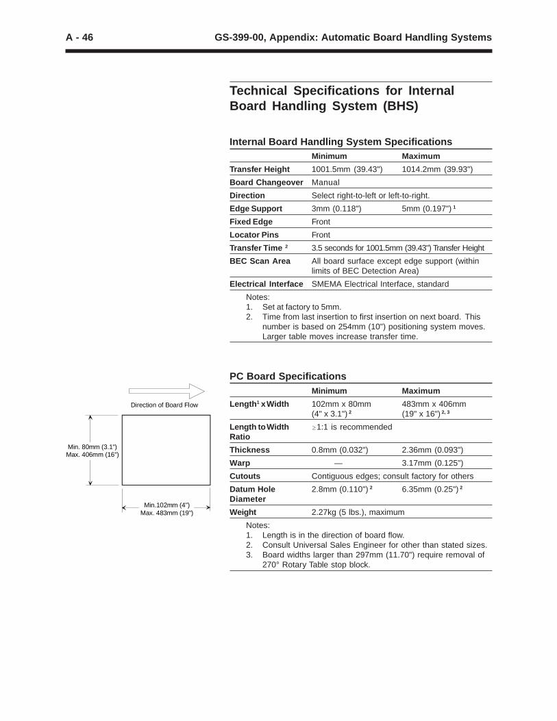
Min. 80mm (3.1") Max. 406mm (16")
Min.102mm (4") Max. 483mm (19")
Direction of Board Flow
Technical Specifications for InternalBoard Handling System (BHS)
Internal Board Handling System SpecificationsMinimum Maximum
Transfer Height 1001.5mm (39.43") 1014.2mm (39.93")
Board Changeover Manual
Direction Select right-to-left or left-to-right.
Edge Support 3mm (0.118") 5mm (0.197") 1
Fixed Edge Front
Locator Pins Front
Transfer Time 2 3.5 seconds for 1001.5mm (39.43") Transfer Height
BEC Scan Area All board surface except edge support (withinlimits of BEC Detection Area)
Electrical Interface SMEMA Electrical Interface, standard
Notes:1. Set at factory to 5mm.2. Time from last insertion to first insertion on next board. This
number is based on 254mm (10") positioning system moves.Larger table moves increase transfer time.
PC Board SpecificationsMinimum Maximum
Length 1 x Width 102mm x 80mm 483mm x 406mm(4" x 3.1") 2 (19" x 16") 2, 3
Length to Width $1:1 is recommendedRatio
Thickness 0.8mm (0.032") 2.36mm (0.093")
Warp — 3.17mm (0.125")
Cutouts Contiguous edges; consult factory for others
Datum Hole 2.8mm (0.110") 2 6.35mm (0.25") 2
Diameter
Weight 2.27kg (5 lbs.), maximum
Notes:1. Length is in the direction of board flow.2. Consult Universal Sales Engineer for other than stated sizes.3. Board widths larger than 297mm (11.70") require removal of
270° Rotary Table stop block.
A - 47GS-399-00, Appendix: Automatic Board Handling Systems
Board Handling
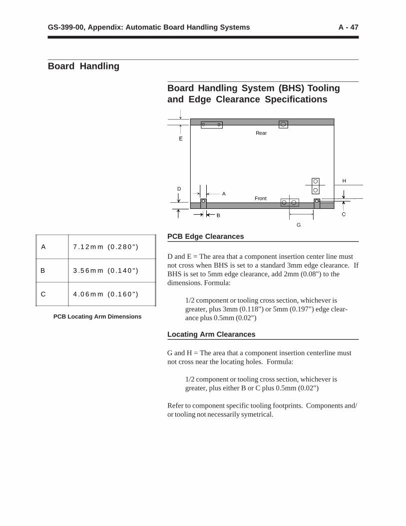
Board Handling System (BHS) Toolingand Edge Clearance Specifications
PCB Edge Clearances
D and E = The area that a component insertion center line mustnot cross when BHS is set to a standard 3mm edge clearance. IfBHS is set to 5mm edge clearance, add 2mm (0.08") to thedimensions. Formula:
1/2 component or tooling cross section, whichever isgreater, plus 3mm (0.118") or 5mm (0.197") edge clear-ance plus 0.5mm (0.02")
G and H = The area that a component insertion centerline must not cross near the locating holes. Formula:
1/2 component or tooling cross section, whichever isgreater, plus either B or C plus 0.5mm (0.02")
Refer to component specific tooling footprints. Components and/or tooling not necessarily symetrical.
PCB Locating Arm Dimensions
G
Locating Arm Clearances
A 7 .1 2 m m (0 .2 8 0 " )
B 3 .5 6 m m (0 .1 4 0 " )
C 4 .0 6 m m (0 .1 6 0 " )
Rear
Front
H
A
B
D
A - 48 GS-399-00, Appendix: Automatic Board Handling Systems
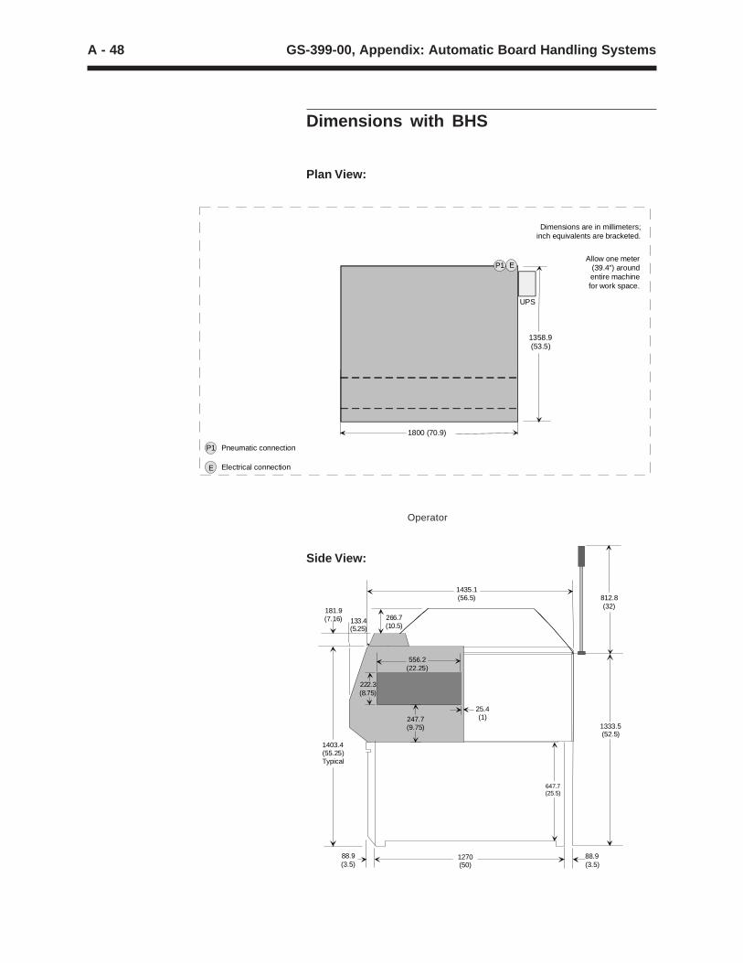
Plan View:
Operator
181.9(7.16) 133.4
(5.25)
1435.1(56.5) 812.8
(32)
1333.5(52.5)
88.9(3.5)
1270(50)
88.9(3.5)
1403.4(55.25)Typical
556.2(22.25)
222.3(8.75)
247.7(9.75)
25.4(1)
647.7(25.5)
266.7(10.5)
Dimensions with BHS
Side View:
P1
E
Pneumatic connection
Electrical connection
Allow one meter (39.4") around entire machine for work space.
Dimensions are in millimeters;inch equivalents are bracketed.
1800 (70.9)
1358.9 (53.5)
P1 E
UPS
A - 49GS-399-00, Appendix: Automatic Board Handling Systems
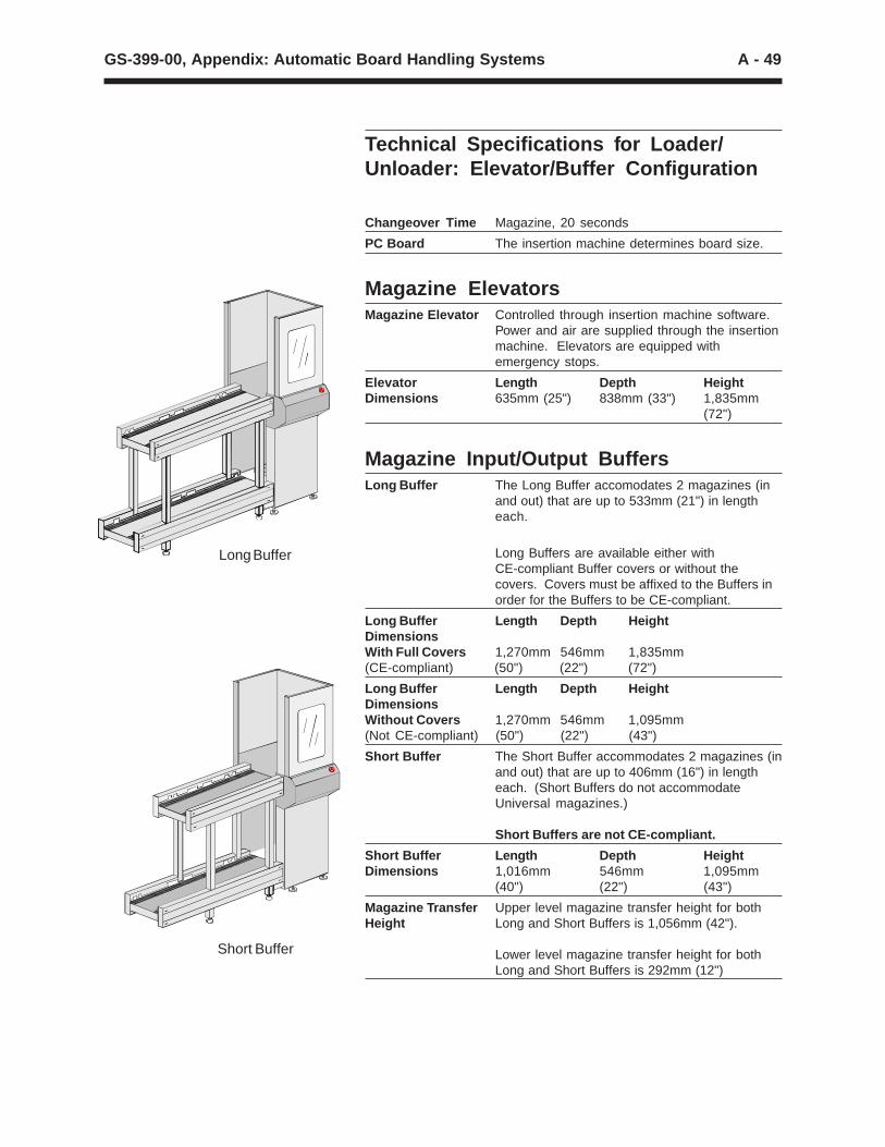
Technical Specifications for Loader/Unloader: Elevator/Buffer Configuration
Long Buffer
Short Buffer
Changeover Time Magazine, 20 seconds
PC Board The insertion machine determines board size.
Magazine ElevatorsMagazine Elevator Controlled through insertion machine software.
Power and air are supplied through the insertionmachine. Elevators are equipped withemergency stops.
Elevator Length Depth HeightDimensions 635mm (25") 838mm (33") 1,835mm
(72")
Magazine Input/Output BuffersLong Buffer The Long Buffer accomodates 2 magazines (in
and out) that are up to 533mm (21") in lengtheach.
Long Buffers are available either withCE-compliant Buffer covers or without thecovers. Covers must be affixed to the Buffers inorder for the Buffers to be CE-compliant.
Long Buffer Length Depth HeightDimensionsWith Full Covers 1,270mm 546mm 1,835mm(CE-compliant) (50") (22") (72")
Long Buffer Length Depth HeightDimensionsWithout Covers 1,270mm 546mm 1,095mm(Not CE-compliant) (50") (22") (43")
Short Buffer The Short Buffer accommodates 2 magazines (inand out) that are up to 406mm (16") in lengtheach. (Short Buffers do not accommodateUniversal magazines.)
Short Buffers are not CE-compliant.
Short Buffer Length Depth HeightDimensions 1,016mm 546mm 1,095mm
(40") (22") (43")
Magazine Transfer Upper level magazine transfer height for bothHeight Long and Short Buffers is 1,056mm (42").
Lower level magazine transfer height for bothLong and Short Buffers is 292mm (12")

A - 50 GS-399-00, Appendix: Automatic Board Handling Systems
MagazinesMaximum 45kg (100lbs) for PC boards plus magazines.Magazine Weight Compatible with most commonly-used
magazines. Consult your Universal SalesEngineer.
Maximum Magazine Maximum Maximum Maximum MaximumDimensions for Length Depth Height WeightLong Buffer (including
PC boards)
533mm 460mm 606mm 45kg(21") (18") (24") (100lbs)
Maximum Magazine Maximum Maximum Maximum MaximumDimensions for Length Depth Height WeightShort Buffer (including
PC boards)
406mm 460mm 606mm 45kg(16") (18") (24") (100lbs)
Optional Magazine An optional magazine gate control is availableGate Control for use with magazines that include a spring-
loaded gate, used to keep PC boards retainedwithin the magazine.
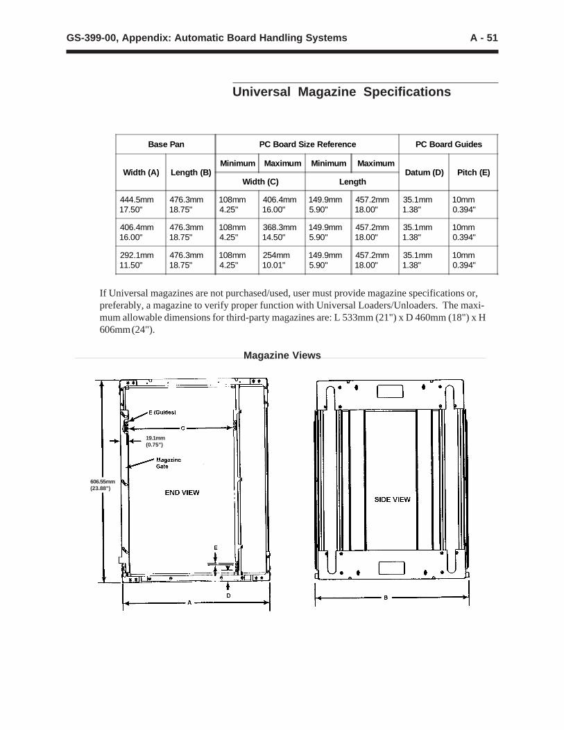
A - 51GS-399-00, Appendix: Automatic Board Handling Systems
Universal Magazine Specifications
Magazine Views
606.55mm(23.88")
19.1mm(0.75")
Base Pan PC Board Size Reference PC Board Guides
Width (A) Length (B)Minimum Maximum Minimum Maximum
Datum (D) Pitch (E)Width (C) Length
444.5mm17.50"
476.3mm18.75"
108mm4.25"
406.4mm16.00"
149.9mm5.90"
457.2mm18.00"
35.1mm1.38"
10mm0.394"
406.4mm16.00"
476.3mm18.75"
108mm4.25"
368.3mm14.50"
149.9mm5.90"
457.2mm18.00"
35.1mm1.38"
10mm0.394"
292.1mm11.50"
476.3mm18.75"
108mm4.25"
254mm10.01"
149.9mm5.90"
457.2mm18.00"
35.1mm1.38"
10mm0.394"
If Universal magazines are not purchased/used, user must provide magazine specifications or,preferably, a magazine to verify proper function with Universal Loaders/Unloaders. The maxi-mum allowable dimensions for third-party magazines are: L 533mm (21") x D 460mm (18") x H606mm (24").
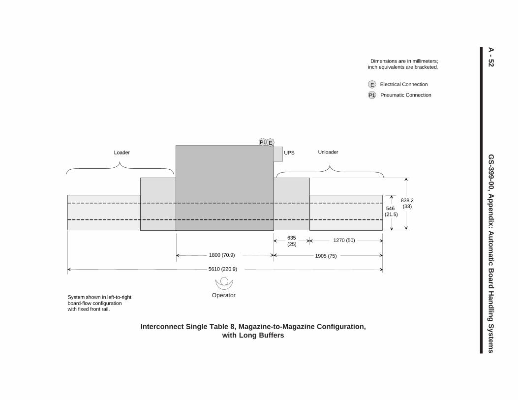
A - 52
GS
-399-00, Appendix: A
utomatic B
oard Handling S
ystems
Interconnect Single Table 8, Magazine-to-Magazine Configuration,with Long Buffers
System shown in left-to-rightboard-flow configurationwith fixed front rail.
Dimensions are in millimeters;inch equivalents are bracketed.
546 (21.5)
838.2(33)
1270 (50)635(25)
Unloader
1905 (75)1800 (70.9)
Loader
P1 E
P1
E Electrical Connection
Pneumatic Connection
5610 (220.9)
UPS
Operator
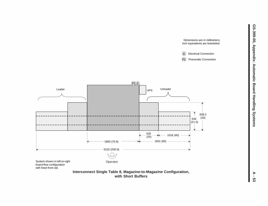
A - 53
GS
-399-00, Appendix: A
utomatic B
oard Handling S
ystems
Interconnect Single Table 8, Magazine-to-Magazine Configuration,with Short Buffers
System shown in left-to-rightboard-flow configurationwith fixed front rail.
Dimensions are in millimeters;inch equivalents are bracketed.
546 (21.5)
838.2(33)
635(25)
Unloader
1800 (70.9)
Loader
1016 (40)
1651 (65)
5102 (200.9)
P1 E
UPS
P1
E Electrical Connection
Pneumatic Connection
Operator
A - 54 GS-399-00, Appendix: Automatic Board Handling Systems
Technical Specifications for Loader/Unloader: Vacuum Bare Board-to-Magazine Configuration
PC Board Specifications for Vacuum Bare Board LoaderMinimum Maximum
Length 1 x Width 127mm x 102mm 457mm x 406mm(5" x 4") 2 (18" x 16") 2
Length to Width $1:1 is recommended.Ratio
Thickness 0.76mm (0.030") 2.36mm (0.093")
Warp — 2.36mm (0.093")
Cutouts Contiguous edges
Stack, Maximum 250 boards at a nominal thickness of 1.57mm(0.062") is the maximum stack height of 394mm(15.5").
Notes:
1. Length is in the direction of board flow.
2. The Interconnect ST 8 determines board size. Consult yourUniversal Sales Engineer for boards larger than 356mm (14").
Vacuum Length Depth HeightBare Board 751.1mm 689.1mm 1574.8mmDimensions (29.57") (29.13") (62")
PC Board Specifications for Between Machines 22"Conveyor
Minimum Maximum
Length 1 x Width 76mm x 51mm 508mm x 457mm(3" x 2") 2 (20" x 18") 2
Length to Width $1:1 is recommended.Ratio
Thickness 0.64mm (0.025") 3.18mm (0.125")
Warp — 3.18mm (0.125")
Notes:
1. Length is in the direction of board flow.
2. The Interconnect ST 8 determines board size. Consult yourUniversal Sales Engineer for boards larger than 356mm (14").
Length Depth Height 1
22" Conveyor 559mm 802.6mm 962.7mmDimensions (22") (31.6") (37.9")
Notes:
1. Height represents pre-set transfer height of conveyor bed.Transfer height is adjustable from 812.8mm (32") to1066.8mm (42").
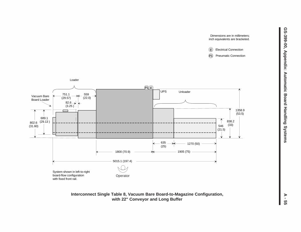
A - 55
GS
-399-00, Appendix: A
utomatic B
oard Handling S
ystems
Interconnect Single Table 8, Vacuum Bare Board-to-Magazine Configuration,with 22" Conveyor and Long Buffer
PE E
System shown in left-to-rightboard-flow configurationwith fixed front rail.
Dimensions are in millimeters;inch equivalents are bracketed.
5015.1 (197.4)
546 (21.5)
838.2(33)
1270 (50)635(25)
Unloader
1905 (75)1800 (70.9)
82.6(3.25 )
Vacuum BareBoard Loader
689.1(29.13 ) 802.6
(31.60)
Loader
559 (22.0)
751.1 (29.57)
P1 EUPS
P1
E Electrical Connection
Pneumatic Connection
1358.9(53.5)
Operator
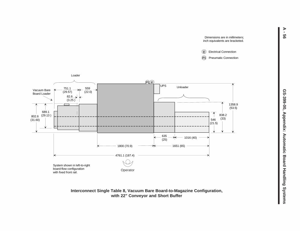
A - 56
GS
-399-00, Appendix: A
utomatic B
oard Handling S
ystems
Interconnect Single Table 8, Vacuum Bare Board-to-Magazine Configuration,with 22" Conveyor and Short Buffer
PE E
System shown in left-to-rightboard-flow configurationwith fixed front rail.
Dimensions are in millimeters;inch equivalents are bracketed.
546 (21.5)
838.2(33)
635(25)
Unloader
1800 (70.9)
82.6(3.25 )
Vacuum BareBoard Loader
689.1(29.13 ) 802.6
(31.60)
Loader
559 (22.0)
751.1 (29.57)
1016 (40)
1651 (65)
4761.1 (187.4)
P1 EUPS
P1
E Electrical Connection
Pneumatic Connection
1358.9(53.5)
Operator
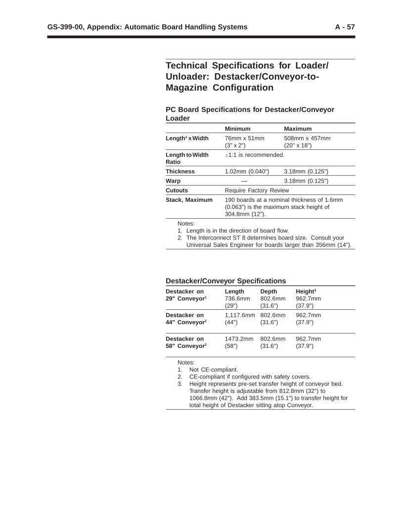
A - 57GS-399-00, Appendix: Automatic Board Handling Systems
Technical Specifications for Loader/Unloader: Destacker/Conveyor-to-Magazine Configuration
PC Board Specifications for Destacker/ConveyorLoader
Minimum Maximum
Length 1 x Width 76mm x 51mm 508mm x 457mm(3" x 2") (20" x 18")
Length to Width $1:1 is recommended.Ratio
Thickness 1.02mm (0.040") 3.18mm (0.125")
Warp — 3.18mm (0.125")
Cutouts Require Factory Review
Stack, Maximum 190 boards at a nominal thickness of 1.6mm(0.063") is the maximum stack height of304.8mm (12").
Notes:1. Length is in the direction of board flow.2. The Interconnect ST 8 determines board size. Consult your
Universal Sales Engineer for boards larger than 356mm (14").
Destacker/Conveyor SpecificationsDestacker on Length Depth Height 3
29" Conveyor 1 736.6mm 802.6mm 962.7mm(29") (31.6") (37.9")
Destacker on 1,117.6mm 802.6mm 962.7mm44" Conveyor 2 (44") (31.6") (37.9")
Destacker on 1473.2mm 802.6mm 962.7mm58" Conveyor 2 (58") (31.6") (37.9")
Notes:1. Not CE-compliant.2. CE-compliant if configured with safety covers.3. Height represents pre-set transfer height of conveyor bed.
Transfer height is adjustable from 812.8mm (32") to1066.8mm (42"). Add 383.5mm (15.1") to transfer height fortotal height of Destacker sitting atop Conveyor.
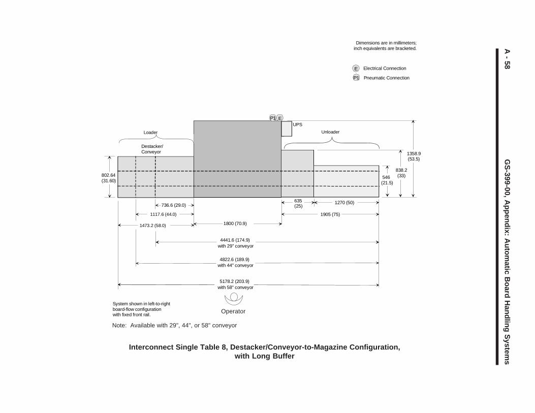
A - 58
GS
-399-00, Appendix: A
utomatic B
oard Handling S
ystemsInterconnect Single Table 8, Destacker/Conveyor-to-Magazine Configuration,
with Long Buffer
Note: Available with 29", 44", or 58" conveyor
System shown in left-to-rightboard-flow configurationwith fixed front rail.
802.64 (31.60)
736.6 (29.0)
Destacker/Conveyor
Loader
4441.6 (174.9)with 29" conveyor
1117.6 (44.0)
4822.6 (189.9)with 44" conveyor
Dimensions are in millimeters;inch equivalents are bracketed.
546 (21.5)
838.2(33)
1270 (50)635(25)
Unloader
1905 (75)
1800 (70.9)1473.2 (58.0)
5178.2 (203.9)with 58" conveyor
P1 EUPS
1358.9(53.5)
P1
E Electrical Connection
Pneumatic Connection
Operator
A - 59
GS
-399-00, Appendix: A
utomatic B
oard Handling S
ystems
Interconnect Single Table 8, Destacker/Conveyor-to-Magazine Configuration,with Short Buffer
Note: Available with 29", 44", or 58" conveyor
System shown in left-to-rightboard-flow configurationwith fixed front rail.
4187.6 (164.9)with 29" conveyor
4568.6 (179.9)with 44" conveyor
Dimensions are in millimeters; inch equivalents are bracketed.
546 (21.5)
838.2(33)
635(25)
Unloader
1651 (65)
1473.2 (58.0)
4924.2 (193.9)with 58" conveyor
1016 (40)
802.64 (31.60)
736.6 (29.0)
Destacker/Conveyor
Loader
P1 EUPS
P1
E Electrical Connection
Pneumatic Connection
1358.9(53.5)
1117.6 (44.0)
1473.2 (58.0) 1800 (70.9)
Operator
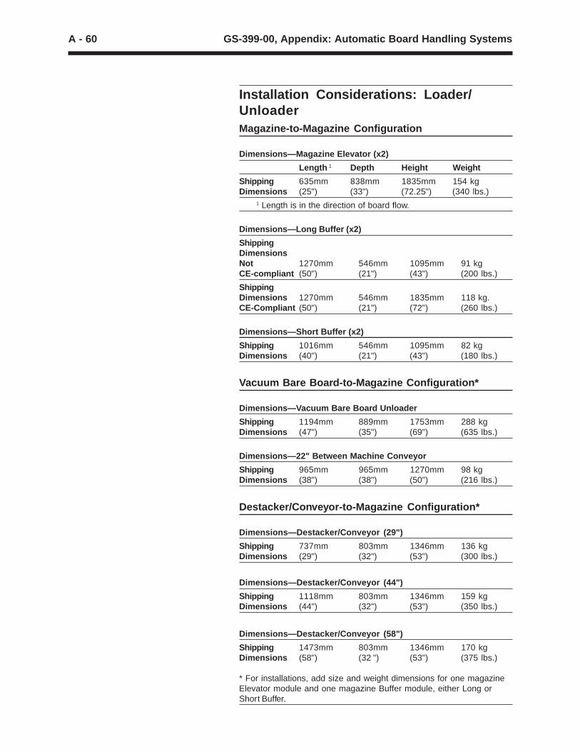
A - 60 GS-399-00, Appendix: Automatic Board Handling Systems
Installation Considerations: Loader/UnloaderMagazine-to-Magazine Configuration
Dimensions—Magazine Elevator (x2)
Length 1 Depth Height Weight
Shipping 635mm 838mm 1835mm 154 kgDimensions (25") (33") (72.25") (340 lbs.)
1 Length is in the direction of board flow.
Dimensions—Long Buffer (x2)
ShippingDimensionsNot 1270mm 546mm 1095mm 91 kgCE-compliant (50") (21") (43") (200 lbs.)
ShippingDimensions 1270mm 546mm 1835mm 118 kg.CE-Compliant (50") (21") (72") (260 lbs.)
Dimensions—Short Buffer (x2)
Shipping 1016mm 546mm 1095mm 82 kgDimensions (40") (21") (43") (180 lbs.)
Vacuum Bare Board-to-Magazine Configuration*
Dimensions—Vacuum Bare Board Unloader
Shipping 1194mm 889mm 1753mm 288 kgDimensions (47") (35") (69") (635 lbs.)
Dimensions—22" Between Machine Conveyor
Shipping 965mm 965mm 1270mm 98 kgDimensions (38") (38") (50") (216 lbs.)
Destacker/Conveyor-to-Magazine Configuration*
Dimensions—Destacker/Conveyor (29")
Shipping 737mm 803mm 1346mm 136 kgDimensions (29") (32") (53") (300 lbs.)
Dimensions—Destacker/Conveyor (44")
Shipping 1118mm 803mm 1346mm 159 kgDimensions (44") (32") (53") (350 lbs.)
Dimensions—Destacker/Conveyor (58")
Shipping 1473mm 803mm 1346mm 170 kgDimensions (58") (32 ") (53") (375 lbs.)
* For installations, add size and weight dimensions for one magazineElevator module and one magazine Buffer module, either Long orShort Buffer.
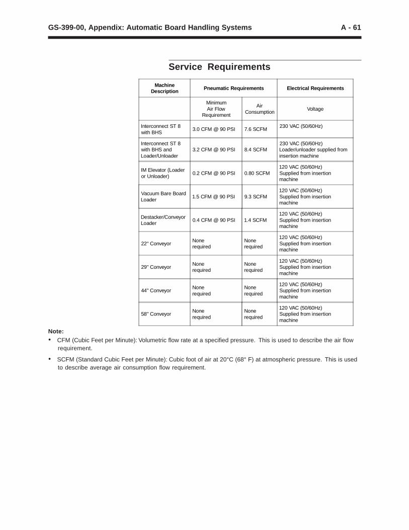
A - 61GS-399-00, Appendix: Automatic Board Handling Systems
Note:• CFM (Cubic Feet per Minute): Volumetric flow rate at a specified pressure. This is used to describe the air flow
requirement.
• SCFM (Standard Cubic Feet per Minute): Cubic foot of air at 20°C (68° F) at atmospheric pressure. This is usedto describe average air consumption flow requirement.
MachineDescription Pneumatic Requirements Electrical Requirements
MinimumAir Flow
Requirement
AirConsumption
Voltage
Interconnect ST 8with BHS
3.0 CFM @ 90 PSI 7.6 SCFM230 VAC (50/60Hz)
Interconnect ST 8with BHS andLoader/Unloader
3.2 CFM @ 90 PSI 8.4 SCFM230 VAC (50/60Hz)Loader/unloader supplied frominsertion machine
IM Elevator (Loaderor Unloader)
0.2 CFM @ 90 PSI 0.80 SCFM120 VAC (50/60Hz)Supplied from insertionmachine
Vacuum Bare BoardLoader
1.5 CFM @ 90 PSI 9.3 SCFM120 VAC (50/60Hz)Supplied from insertionmachine
Destacker/ConveyorLoader
0.4 CFM @ 90 PSI 1.4 SCFM120 VAC (50/60Hz)Supplied from insertionmachine
22" ConveyorNonerequired
Nonerequired
120 VAC (50/60Hz)Supplied from insertionmachine
29" ConveyorNonerequired
Nonerequired
120 VAC (50/60Hz)Supplied from insertionmachine
44" ConveyorNonerequired
Nonerequired
120 VAC (50/60Hz)Supplied from insertionmachine
58" ConveyorNonerequired
Nonerequired
120 VAC (50/60Hz)Supplied from insertionmachine
Service Requirements


