24
S800 ENC
S800 ENC

S800 ENC 2 532116 - Rev.A
FAAC S.p.A. Soc. Unipersonale
Via Calari, 10 - 40069 Zola Predosa BOLOGNA - ITALY
Tel. +39 051 61724 - Fax +39 051 758518
www.faac.it - www.faacgroup.com
© Copyright FAAC S.p.A. dal 2016. Tutti i diritti riservati.
Nessuna parte di questo manuale può essere riprodotta, archiviata, distribuita a terzi né altrimenti copiata, in qualsiasi formato e con qualsiasi mezzo, sia esso elettronico, meccanico o tramite fotocopia, senza il preventivo consenso scritto di FAAC S.p.A.
Tutti i nomi e i marchi citati sono di proprietà dei rispettivi fabbricanti.
I clienti possono effettuare copie per esclusivo utilizzo proprio.
Questo manuale è stato pubblicato nel 2016.
© Copyright FAAC S.p.A. from 2016. All rights reserved.
No part of this manual may be reproduced, archived, distributed to third parties nor copied in any other way, in any format and with any means, be it electronic, mechanical or by photocopying, without prior written authorisation by FAAC S.p.A.
All names and trademarks mentioned are the property of their respective manufac-turers.
Customers may make copies exclusively for their own use.
This manual was published in 2016.
© Copyright FAAC S.p.A. depuis 2016. Tous droits réservés.
Aucune partie de ce manuel ne peut être reproduite, archivée ou distribuée à des tiers ni copiée, sous tout format et avec tout moyen, qu’il soit électronique, mécanique ou par photocopie, sans le consentement écrit préalable de FAAC S.p.A.
Tous les noms et les marques cités sont la propriété de leurs fabricants respectifs.
Les clients peuvent faire des copies pour leur usage exclusif.
Ce manuel a été publié en 2016.
© Copyright FAAC S.p.A. ab dem 2016. Alle Rechte vorbehalten.
Kein Teil dieses Handbuchs darf reproduziert, gespeichert, an Dritte weitergegeben oder sonst auf eine beliebige Art in einem beliebigen Format und mit beliebigen Mitteln kopiert werden, weder mit elektronischen, noch mechanischen oder durch Fotokopieren, ohne die Genehmigung von FAAC S.p.A.
Alle erwähnten Namen und Marken sind Eigentum der jeweiligen Hersteller.
Die Kunden dürfen nur für den Eigengebrauch Kopien anfertigen.
Dieses Handbuch wurde 2016 veröffentlicht.
© Copyright FAAC S.p.A. del 2016. Todos los derechos están reservados.
No puede reproducirse, archivarse, distribuirse a terceros ni copiarse de ningún modo, ninguna parte de este manual, con medios mecánicos o mediante fotocopia, sin el permiso previo por escrito de FAAC S.p.A.
Todos los nombre y las marcas citadas son de propiedad de los respectivos fabricantes.
Los clientes pueden realizar copias para su uso exclusivo.
Este manual se ha publicado en 2016.
© Copyright FAAC S.p.A. van 2016. Alle rechten voorbehouden.
Niets uit deze handleiding mag gereproduceerd, gearchiveerd, aan derden openbaar gemaakt of op andere wijze gekopieerd worden, in om het even welke vorm en met geen enkel middel, noch elektronisch, mechanisch of via fotokopiëren, zonder schrfitelijke toestemming vooraf van FAAC S.p.A.
Alle vermelde namen en merken zijn eigendom van de respectievelijke fabrikanten.
De klanten mogen kopieën maken die enkel voor eigen gebruik bestemd zijn.
Dez handleiding werd in 2016 gepubliceerd.
S800 ENC 1 532116 - Rev.A
Tran
slatio
n of
the
orig
inal
inst
ruct
ions
ENGLIS
H
EC DECLARATION OF CONFORMITY
The Manufacturer
Company name: FAAC S.p.A. Soc. Unipersonale
Address: Via Calari, 10 - 40069 Zola Predosa BOLOGNA - ITALY
hereby declares that the following products:
Description: Underground actuator for swing gates
Model: S800 ENC 100° CBAC 230V; S800 ENC 180° CBAC 230V;
S800 ENC 100° SBW 230V; S800 ENC 180° SBW 230V
comply with the following applicable EU legislations:
Directive EMC 2004/108/EC
Directive ROHS 2 2011/65/EU
Furthermore, the following harmonised standards have been applied:
Bologna, 01-01-2016
EN 61000-6-2:2005
EN 61000-6-3:2007
CEO
DECLARATION OF INCORPORATION OF PARTLY
COMPLETED MACHINERY
(2006/42/EC ANN.II P.1, LETT. B)Manufacturer and person authorised to prepare the relevant technical documentation
Company name: FAAC S.p.A. Soc. Unipersonale
Address: Via Calari, 10 - 40069 Zola Predosa BOLOGNA - ITALY
hereby declares that for the partly completed machinery:
Description: Underground actuator for swing gates
Model: S800 ENC 100° CBAC 230V; S800 ENC 180° CBAC 230V;
S800 ENC 100° SBW 230V; S800 ENC 180° SBW 230V
the following essential requirements of the Machinery Directive 2006/42/EC (including all applicable amendments) have been applied and met:
EHSR 1.1.2, 1.1.4, 1.1.5, 1.1.6, 1.1.7, 1.2.3.4, 1.3.1, 1.3.2, 1.3.3, 1.3.7, 1.3.8.1, 1.3.8.2, 1.3.10, 1.3.11.1, 1.3.11.2, 1.4.1, 1.4.5, 1.4.6, 1.4.8, 1.4.9, 1.4.15, 1.5.3, 1.5.4, 1.5.15, 1.6.1, 1.6.1.1
and that the relevant technical documentation has been compiled in compliance with part B of Annex VII.
Furthermore, the following harmonised standards have been applied:
EN 12453:2000
EN12100:2010
EN13849-1:2008
EN13849-2:2008
It is also declared that the partly completed machinery identified above may not be com-missioned until the final machine - into which it will be incorporated - has been declared complaint with the provisions of the above mentioned Machine Directive 2006/42/EC.
Bologna, 01-01-2016 CEO
ANNEX1 The limits of use of S800 ENC in relation to the wind . . . . . . . . . . . . . . . 1 82 Limits of use of the positive stops . . . . . . . . . . . . . . . . . . . . . . . . . . . . . . . . . 1 83 Foundation for leaf of MAX weight and width . . . . . . . . . . . . . . . . . . . . . 1 9
TABLES1 Symbols: notes and warnings on the instructions . . . . . . . . . . . . . . . . . . . . 22 Symbols: safety recommendations (EN ISO 7010) . . . . . . . . . . . . . . . . . . . . 23 Symbols: Personal Protective Equipment . . . . . . . . . . . . . . . . . . . . . . . . . . . . 34 Symbols: signs on the packaging. . . . . . . . . . . . . . . . . . . . . . . . . . . . . . . . . . . . 45 Technical data . . . . . . . . . . . . . . . . . . . . . . . . . . . . . . . . . . . . . . . . . . . . . . . . . . . . . 66 Symbols: work equipment (type and size) . . . . . . . . . . . . . . . . . . . . . . . . . 1 07 Guide to solving malfunctions . . . . . . . . . . . . . . . . . . . . . . . . . . . . . . . . . . . . 1 58 Routine maintenance . . . . . . . . . . . . . . . . . . . . . . . . . . . . . . . . . . . . . . . . . . . . 1 6
CONTENTSEC Declaration of conformity . . . . . . . . . . . . . . . . . . . . . . . . . . . . . . . . . . . 1Declaration of incorporation of partly completed machinery 1
1. INTRODUCTION TO THE INSTRUCTION MANUAL . . . . . . . . . . . 21.1 Meaning of the symbols . . . . . . . . . . . . . . . . . . . . . . . . . . . . . . . . . . . . . . . . . 2
2. SAFETY RECOMMENDATIONS . . . . . . . . . . . . . . . . . . . . . . . . . . . . . . . . . . 32.1 Installer safety . . . . . . . . . . . . . . . . . . . . . . . . . . . . . . . . . . . . . . . . . . . . . . . . . . . . 32.2 Transport and storage . . . . . . . . . . . . . . . . . . . . . . . . . . . . . . . . . . . . . . . . . . . . 42.3 Unpacking and handling . . . . . . . . . . . . . . . . . . . . . . . . . . . . . . . . . . . . . . . . 42.4 Product waste disposal . . . . . . . . . . . . . . . . . . . . . . . . . . . . . . . . . . . . . . . . . . 4
3. S800 ENC . . . . . . . . . . . . . . . . . . . . . . . . . . . . . . . . . . . . . . . . . . . . . . . . . . . . . . . . . . . . 53.1 Intended use . . . . . . . . . . . . . . . . . . . . . . . . . . . . . . . . . . . . . . . . . . . . . . . . . . . . . . 53.2 Limits of use . . . . . . . . . . . . . . . . . . . . . . . . . . . . . . . . . . . . . . . . . . . . . . . . . . . . . . . 53.3 Unauthorised use . . . . . . . . . . . . . . . . . . . . . . . . . . . . . . . . . . . . . . . . . . . . . . . . . 53.4 Use in an emergency . . . . . . . . . . . . . . . . . . . . . . . . . . . . . . . . . . . . . . . . . . . . . 53.5 Product identification . . . . . . . . . . . . . . . . . . . . . . . . . . . . . . . . . . . . . . . . . . . . 53.6 Technical specifications . . . . . . . . . . . . . . . . . . . . . . . . . . . . . . . . . . . . . . . . . . 63.7 Identification of components . . . . . . . . . . . . . . . . . . . . . . . . . . . . . . . . . . . 7
Installation accessories (supplied separately) . . . . . . . . . . . . . . . . 7
4. INSTALLATION REQUIREMENTS . . . . . . . . . . . . . . . . . . . . . . . . . . . . . . . . 84.1 Mechanical requirements . . . . . . . . . . . . . . . . . . . . . . . . . . . . . . . . . . . . . . . . 84.2 Electric system . . . . . . . . . . . . . . . . . . . . . . . . . . . . . . . . . . . . . . . . . . . . . . . . . . . . 94.3 Typical system . . . . . . . . . . . . . . . . . . . . . . . . . . . . . . . . . . . . . . . . . . . . . . . . . . . . . 9
5. INSTALLATION . . . . . . . . . . . . . . . . . . . . . . . . . . . . . . . . . . . . . . . . . . . . . . . . . . . 105.1 Required tools . . . . . . . . . . . . . . . . . . . . . . . . . . . . . . . . . . . . . . . . . . . . . . . . . . . 105.2 Remove the leaf and lower hinge . . . . . . . . . . . . . . . . . . . . . . . . . . . . . . 105.3 Put in the foundation box . . . . . . . . . . . . . . . . . . . . . . . . . . . . . . . . . . . . . . 105.4 Set up the guide bracket . . . . . . . . . . . . . . . . . . . . . . . . . . . . . . . . . . . . . . . . 115.5 Installing the leaf . . . . . . . . . . . . . . . . . . . . . . . . . . . . . . . . . . . . . . . . . . . . . . . . 115.6 Installing the actuator. . . . . . . . . . . . . . . . . . . . . . . . . . . . . . . . . . . . . . . . . . . 125.7 Adjusting the positive stops . . . . . . . . . . . . . . . . . . . . . . . . . . . . . . . . . . . . 13
6. START-UP. . . . . . . . . . . . . . . . . . . . . . . . . . . . . . . . . . . . . . . . . . . . . . . . . . . . . . . . . . 146.1 Force adjustment (By-Pass) . . . . . . . . . . . . . . . . . . . . . . . . . . . . . . . . . . . . . 14
Closure of the box . . . . . . . . . . . . . . . . . . . . . . . . . . . . . . . . . . . . . . . . . . . . . . 146.2 Final operations . . . . . . . . . . . . . . . . . . . . . . . . . . . . . . . . . . . . . . . . . . . . . . . . . . 14
7. MAINTENANCE . . . . . . . . . . . . . . . . . . . . . . . . . . . . . . . . . . . . . . . . . . . . . . . . . . . 157.1 Routine maintenance . . . . . . . . . . . . . . . . . . . . . . . . . . . . . . . . . . . . . . . . . . . 157.2 Operating problems . . . . . . . . . . . . . . . . . . . . . . . . . . . . . . . . . . . . . . . . . . . . . 15
Bleeding . . . . . . . . . . . . . . . . . . . . . . . . . . . . . . . . . . . . . . . . . . . . . . . . . . . . . . . . . 15Topping-up the oil level. . . . . . . . . . . . . . . . . . . . . . . . . . . . . . . . . . . . . . . . 15
8. INSTRUCTIONS FOR USE . . . . . . . . . . . . . . . . . . . . . . . . . . . . . . . . . . . . . . . 178.1 Safety Recommendations . . . . . . . . . . . . . . . . . . . . . . . . . . . . . . . . . . . . . . 178.2 Use in an emergency . . . . . . . . . . . . . . . . . . . . . . . . . . . . . . . . . . . . . . . . . . . . 178.3 Manual operation. . . . . . . . . . . . . . . . . . . . . . . . . . . . . . . . . . . . . . . . . . . . . . . . 17
Release manoeuvre. . . . . . . . . . . . . . . . . . . . . . . . . . . . . . . . . . . . . . . . . . . . . 17Restoring automatic operation . . . . . . . . . . . . . . . . . . . . . . . . . . . . . . . 17
S800 ENC 2 532116 - Rev.A
Tran
slatio
n of
the
orig
inal
inst
ruct
ions
ENGLIS
H
1. INTRODUCTION TO THE INSTRUCTION MANUAL
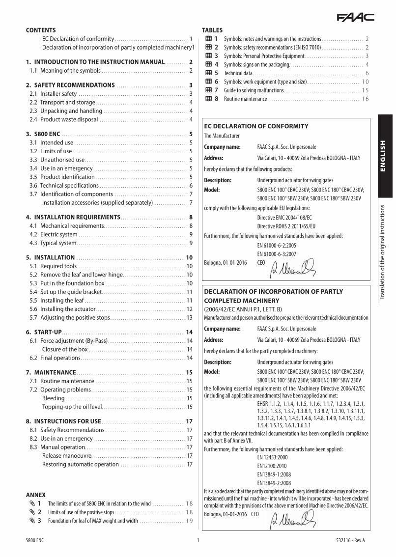
1 Symbols: notes and warnings on the instructions
FATTENTION ELECTROCUTION HAZARD - The operation or step described must be performed in compliance with the provided instructions and safety regulations.
!WARNING: RISK OF PERSONAL INJURY OR DAMAGE TO THE PARTS - The operation or step described must be performed in compliance with the provided instructions and safety regulations.
WARNING - Details and specifications to be followed in order to ensure correct operation of the system.
RECYCLING and DISPOSAL - The constructive components and materials, batteries and electronic components must not be disposed of with household waste but delivered to authorised disposal and recycling facilities.
For manual lifting, arrange for 1 person every 20 kg being lifted.
PAGE E.g.: 6 see Page 6.
FIGURE E.g.: 1 -3 see Figure 1 -detail 3.
TABLE E.g.: 1 see Table 1.
§ CHAPTER/PARAGRAPH E.g.: §1.1 see Paragraph 1.1.
ANNEX E.g: 1 refer to Annex 1.
2 Symbols: safety recommendations (EN ISO 7010)
GENERIC HAZARD
Risk of personal injury or damage to parts.
ELECTROCUTION HAZARD
Risk of electrocution due to the presence of live parts.
RISK OF CRUSHING, MUSCOLO-SKELETAL DISORDERS
Risk of musculoskeletal crushing - Risk of personal injury in case of lifting heavy loads manually.
CRUSHING HAZARD
Risk of crushing hands/feet due to the presence of heavy parts.
CUTTING/AMPUTATION/PIERCING HAZARD
Risk of cutting due to the presence of sharp parts or the use of pointed tools (drill).
SHEARING HAZARD
Risk of shearing due to moving parts.
RISK OF IMPACT/CRUSHING
Risk of impact or crushing due to moving parts.
FALLING OBJECTS HAZARD
Risk of impact due to falling objects.
TRIPPING HAZARD
Risk of tripping due to the presence of thresholds higher than 5 mm.
SPENT BATTERIES HAZARD
Risk for the environment and health arising from spent batteries due to possible leakage of the liquid content.
COLLISION WITH FORKLIFT TRUCKS HAZARD
Risk of collision/impact with forklift trucks.
1.1 MEANING OF THE SYMBOLS
This manual provides the correct procedures and requirements for installation and keeping of S800 ENC in safe conditions.The results of the risk assessment conducted by FAAC S.p.A. on the entire life cycle of the product has been considered when drafting the manual in order to implement effective risk reduction.The following stages of the life cycle of the product have been con-sidered:
- delivery/handling of the supply - assembly and installation - setting up and commissioning - operation - maintenance/resolving any faults - disposal at the end of the product’s life
Risks arising from installation and using the product have been considered:
- risks for the installer/maintenance technician (technical person-nel)
- risks for the automation user - risks for product integrity (damage)
In Europe, the automation of a door/gate falls under the Machinery Directive 2006/42/EC and the relevant harmonised standards. Who-ever automates a door/gate (new or existing) is referred to as the Manufacturer of the Machine. By law, it is therefore required, among other things, to carry out a risk analysis of the machine (automatic door/gate, as a whole) and take protective measures to fulfil the es-sential safety requirements specified in Attachment I of the Machinery Directive. This manual also contains general information and guidelines in a purely illustrative and not exhaustive manner, so as to facilitate the activities carried out by the Manufacturer of the Machine, in all respects, in relation to the risk analysis and drafting instructions for use and maintenance of the machine. It is specifically understood that FAAC S.p.A. does not accept any liability with regard to the reli-ability and/or completeness of the above instructions. Therefore, the manufacturer of the machine must carry out all the activities required by the Machinery Directive and the relevant harmonised standards, according to the actual condition of the locations and structures where the product S800 ENC will be installed, prior to commission-ing the machine. These activities include the analysis of all the risks associated with the machine and subsequent implementation of all safety measures intended to fulfil the essential safety requirements.This manual contains references to European standards. The auto-mation of a door/gate must fully comply with laws, standards and regulations applicable in the country where installation will take place.
Unless otherwise specified, the measurements provided in the instruc-tions are in mm.

S800 ENC 3 532116 - Rev.A
Tran
slatio
n of
the
orig
inal
inst
ruct
ions
ENGLIS
H
3 Symbols: Personal Protective EquipmentPersonal protective equipment must be worn for protection from any risks (e.g. crush-ing, cutting, shearing...):
Obligation to wear head protection helmet.
Obligation to wear safety footwear.
Obligation to wear mask/goggles to protect the eyes from the risk of frag-ments due to the use of drill or welder.
Obligation to wear work gloves.
Obligation to wear ear protectors.
Obligation to wear work clothes without any parts that may get caught in moving parts..
2. SAFETY RECOMMENDATIONS
2.1 INSTALLER SAFETYThis product is placed onto the market as “partly completed machin-ery”, therefore it cannot be commissioned until the machine in which it will be incorporated has been identified and declared to conform to the Machinery Directive 2006/42/EC by the actual Manufacturer.
! Incorrect installation and/or incorrect use of the product might cause serious harm to people. Read and comply with all the instructions before starting any activity on the product. Keep these instructions for future reference.
Perform installation and other activities adhering to the sequences provided in the instructions manual.
Always comply with all the requirements contained in the instructions and warning tables at the beginning of the paragraphs. Always comply with the safety recommendations.
Only the installer and/or maintenance technician is authorised to work on the automation components. Do not modify the original components in any way.
Close off the work site (even temporarily) and prevent access/tran-sit. EC countries must comply with the legislation that transposes the European Construction Site Directive 92/57/EC.
The installer is responsible for the installation/testing of the automa-tion and for completing the Register of the system.The installer must prove or declare to possess technical and profes-sional proficiency to perform installation, testing and maintenance activities according to the requirements in these instructions.
Installation activities require special work conditions to reduce to the minimum the risks of accidents and serious damage. Furthermore, the suitable precautions must be taken to prevent risks of injury to persons or damage.
! The installer must be in good physical and mental condition, aware of and responsible for the hazards that may be generated when using the product.
The work area must be kept tidy and must not be left unattended.
Do not wear clothes or accessories (scarves, bracelets, etc.) that may get caught in moving parts.
Always wear the personal protective equipment recommended for the type of activity to be carried out.
The required level of workplace lighting must be equal to at least 200 lux.
Operate CE marked machinery and equipment in compliance with the manufacturer's instructions. Use work instruments in good conditions.
Use the transport and lifting equipment recommended in the instruc-tions manual.
Use safety-compliant portable ladders of adequate size, fitted with anti-slip devices at the top and bottom, equipped with retainer hooks.
1
S800 ENC 4 532116 - Rev.A
1 2 3
54
Tran
slatio
n of
the
orig
inal
inst
ruct
ions
ENGLIS
H
2.2 TRANSPORT AND STORAGE 2.3 UNPACKING AND HANDLING
RISKS
PERSONAL PROTECTIVE EQUIPMENT
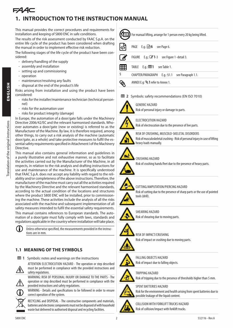
1. Open the package.2. Remove all the components.
! Lift the actuator by the handles.
Make sure all of the components in the supply are present and intact 1 .
3. Dispose of the packaging material.
! The packaging materials (plastic, polystyrene, etc.) must not be left within the reach of children as they are potential sources of danger.
Discard the packaging after use in the appropriate containers in compli-ance with waste disposal regulations.
2.4 PRODUCT WASTE DISPOSAL
4 Symbols: signs on the packaging.
Read the instructions.
Handle with care. Presence of fragile parts.
Upward direction. Do NOT turn over.
Store away from water and humidity.
PROHIBITION to stack the pallets.
5 Maximum number of stackable packages.
CE marking.
SINGLE PACKAGE
RISKS
PERSONAL PROTECTIVE EQUIPMENT
1 S800 ENC
2 Installation support
3 Key
4 Positive stop fastenings
5 Instruction manual
! Follow the instructions on the package while handling it.
Use the forklift truck or pallet truck in observance of the safety rules to avoid risks of collision/impact.
! Follow the instructions on the package while handling it.
PALLETISED SUPPLY
RISKS
PERSONAL PROTECTIVE EQUIPMENT
STORAGE
Store the product in its original packaging, in closed and dry premises, protected from the sun and free from dust and aggressive substances. Protect from mechanical stress. If stored for more than 3 months, regularly check the condition of the components and the packaging.
- Storage temperature: 5°C to 30°C. - Percentage of humidity: 30% to 70%.
After dismantling the product, dispose of it in compliance with Standards in force.
The constructive components and materials, batteries and electronic components must not be disposed of with household waste but de-livered to authorised disposal and recycling facilities. The oil must be collected in a sealed container and handed over to an authorised disposal and recycling facility. Do not mix with other substances such as anti-freeze or transmission fluids. Keep the used oil away from heat sources and out of reach of children.
2
S800 ENC 5 532116 - Rev.A
S800 ENC
FAAC S.p.A. Soc. UnipersonaleVia Calari, 10 - 40069 Zola Predosa BOLOGNAItaly
Tran
slatio
n of
the
orig
inal
inst
ruct
ions
ENGLIS
H
3. S800 ENC
3.1 INTENDED USEUnderground actuators of the FAAC S800 ENC series are designed to activate horizontally moving swing gates for residential/condo-minium use.One underground actuator must be installed for each leaf.The systems set up with S800 ENC must only be intended for vehicle transit.See the instructions in § 8.3 to move the gate by hand.
! Any other use, not specifically described, is prohibited and might affect the integrity of the product and/or be a source of danger.
3.2 LIMITS OF USE
- Do not use the automation when its range of action is not clear of people, animals or objects.
- Do not pass and/or stop within the automation's range of action while it is moving.
- Do not obstruct the movement of the automation. - Do not climb onto, hold onto or be pulled by the leaf. - Do not allow children to come close or play near the automation's
range of action. - Do not allow the control devices to be used by persons who are
not specifically authorised and trained. - Do not allow the control devices to be used by children or persons
with reduced mental-physical abilities, unless under the supervi-sion of an adult responsible for their safety.
! When moving it manually, slowly guide the leaf for its entire stroke, do not push the leaf so it moves freely.
3.4 USE IN AN EMERGENCY
3.3 UNAUTHORISED USE - Any use other than the intended use is prohibited. - It is prohibited to install the automation outside of the limits set
forth in the Technical data and the Installation requirements. - It is prohibited to install the automation along escape routes. - It is prohibited to install the automation to implement smoke
and/or fire protection doors (fire doors). - It is prohibited to install the automation in areas that are at risk of
explosion and/or fire: the presence of flammable gases or fumes poses a severe danger for safety (the product is not certified pursuant to directive 94/9/EC ATEX).
- It is prohibited to power the system with energy sources other than those set forth.
- It is prohibited to integrate unrelated commercial systems and/or equipment, or employ them for uses that are not allowed by the respective manufacturers.
- It is prohibited to use and/or install accessories that are not specifically approved by FAAC S.p.A..
- It is prohibited to use the automation before having commis-sioned the system.
- It is prohibited to use the automation with faults/tampering which could jeopardise safety.
- It is prohibited to use the automation with movable and/or fixed guards that have been tampered with or removed.
- Do not expose the actuator to direct jets of water of any type and amount.
- Do not expose the actuator to chemical or aggressive environ-mental agents.
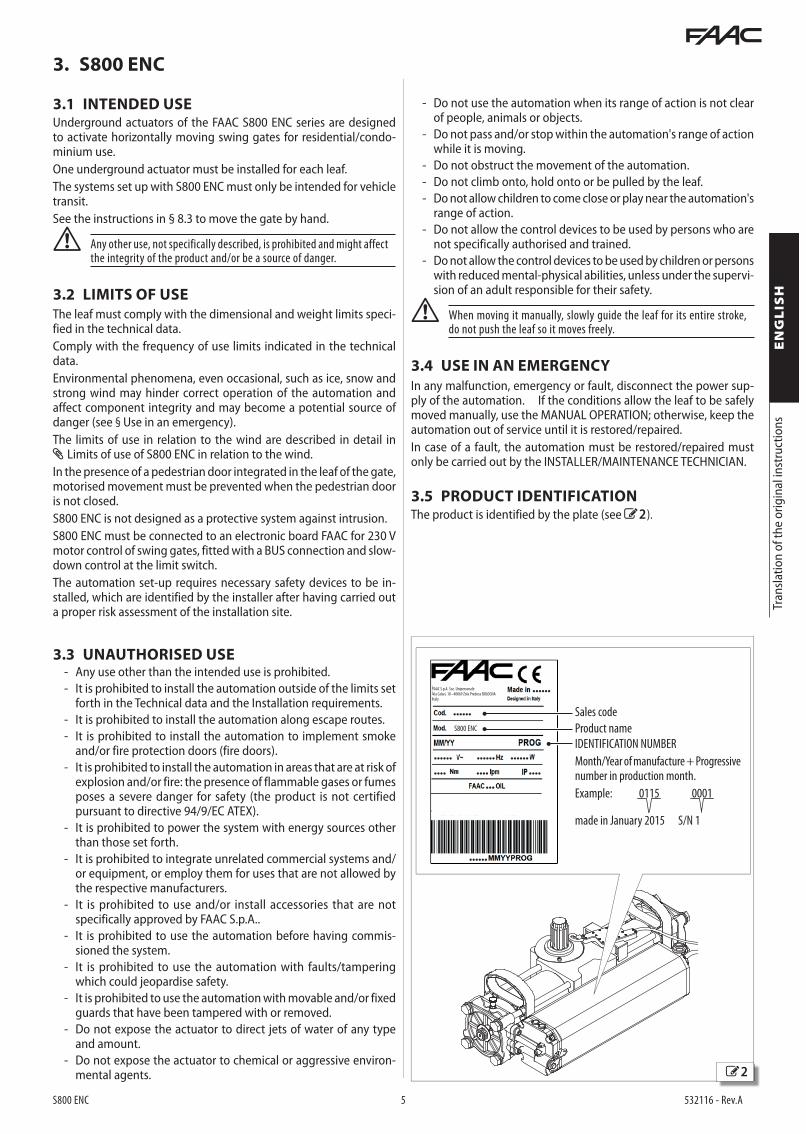
3.5 PRODUCT IDENTIFICATIONThe product is identified by the plate (see 2 ).
Sales code
Product name
IDENTIFICATION NUMBER
Month/Year of manufacture + Progressive number in production month.
Example: 0115 0001
made in January 2015 S/N 1
The leaf must comply with the dimensional and weight limits speci-fied in the technical data.Comply with the frequency of use limits indicated in the technical data.Environmental phenomena, even occasional, such as ice, snow and strong wind may hinder correct operation of the automation and affect component integrity and may become a potential source of danger (see § Use in an emergency).The limits of use in relation to the wind are described in detail in Limits of use of S800 ENC in relation to the wind.In the presence of a pedestrian door integrated in the leaf of the gate, motorised movement must be prevented when the pedestrian door is not closed.S800 ENC is not designed as a protective system against intrusion.S800 ENC must be connected to an electronic board FAAC for 230 V motor control of swing gates, fitted with a BUS connection and slow-down control at the limit switch.The automation set-up requires necessary safety devices to be in-stalled, which are identified by the installer after having carried out a proper risk assessment of the installation site.
In any malfunction, emergency or fault, disconnect the power sup-ply of the automation. If the conditions allow the leaf to be safely moved manually, use the MANUAL OPERATION; otherwise, keep the automation out of service until it is restored/repaired.In case of a fault, the automation must be restored/repaired must only be carried out by the INSTALLER/MAINTENANCE TECHNICIAN.
S800 ENC 6 532116 - Rev.A
Tran
slatio
n of
the
orig
inal
inst
ruct
ions
ENGLIS
H
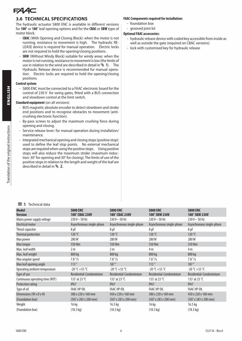
3.6 TECHNICAL SPECIFICATIONSThe hydraulic actuator S800 ENC is available in different versions for 100° or 180° leaf opening options and for the CBAC or SBW type of motor block.
- CBAC (With Opening and Closing Block): when the motor is not running, resistance to movement is high. The hydraulic RE-LEASE device is required for manual operation. Electric locks are not required to hold the opening/closing positions.
- SBW (Without Windy Block) suitable for windy areas: when the motor is not running, resistance to movement is low (the limits of use in relation to the wind are described in detail in 1 ). The Hydraulic Release device is recommended for manual opera-tion. Electric locks are required to hold the opening/closing positions.
Control system
- S800 ENC must be connected to a FAAC electronic board for the control of 230 V for swing gates, fitted with a BUS connection and slowdown control at the limit switch.
Standard equipment (on all versions) - BUS magnetic absolute encoder to detect slowdown and stroke
end positions and to recognise obstacles to movement (anti-crushing electronic function).
- By-pass screws to adjust the maximum crushing force during opening and closing.
- Service release lever: for manual operation during installation/maintenance.
- Integrated mechanical opening and closing stops (positive stop): used to define the leaf stop points. No external mechanical stops are required when using the positive stops. Using positive stops will also reduce the maximum stroke (maximum reduc-tion: 30° for opening and 30° for closing). The limits of use of the positive stops in relation to the length and weight of the leaf are described in detail in 2 .
FAAC Components required for installation:
- foundation box - grooved joint kit
Optional FAAC accessories:
- hydraulic release device with coded key accessible from inside as well as outside the gate (required on CBAC versions)
- lock with customised key for hydraulic release
5 Technical dataModelVersion
S800 ENC100° CBAC 230V
S800 ENC180° CBAC 230V
S800 ENC100° SBW 230V
S800 ENC180° SBW 230V
Mains power supply voltage 230 V~ 50 Hz 230 V~ 50 Hz 230 V~ 50 Hz 230 V~ 50 Hz
Electrical motor Asynchronous single-phase Asynchronous single-phase Asynchronous single-phase Asynchronous single-phase
Thrust capacitor 8 μF 8 μF 8 μF 8 μF
Thermal protection 120 °C 120 °C 120 °C 120 °C
Max power 280 W 280 W 280 W 280 W
Max torque 550 Nm 550 Nm 550 Nm 550 Nm
Max. leaf width 2 m 2 m 4 m 4 m
Max. leaf weight 800 kg 800 kg 800 kg 800 kg
Max angular speed 7.8 °/s 7.8 °/s 7.8 °/s 7.8 °/s
Max leaf opening angle 113 ° 187 ° 113 ° 187 °
Operating ambient temperature -20 °C +55 °C -20 °C +55 °C -20 °C +55 °C -20 °C +55 °C
Type of use Residential-Condominium Residential-Condominium Residential-Condominium Residential-Condominium
Continuous operating time (ROT) 133' at 23 °C 133' at 23 °C 133' at 23 °C 133' at 23 °C
Protection rating IP67 IP67 IP67 IP67
Type of oil FAAC HP OIL FAAC HP OIL FAAC HP OIL FAAC HP OIL
Dimensions (W x D x H)
(Foundation box)
380 x 220 x 160 mm
(507 x 283 x 200 mm)
450 x 220 x 160 mm
(507 x 283 x 200 mm)
380 x 220 x 160 mm
(507 x 283 x 200 mm)
450 x 220 x 160 mm
(507 x 283 x 200 mm)
Weight
(Foundation box)
16 kg
(18.3 kg)
16.5 kg
(18.3 kg)
16 kg
(18.3 kg)
16.5 kg
(18.3 kg)

3
4
S800 ENC 7 532116 - Rev.A
16
5 4 3
78
6
5
1 2 43
15
2017
18
12
14
13
19
10 119
Tran
slatio
n of
the
orig
inal
inst
ruct
ions
ENGLIS
H
3.7 IDENTIFICATION OF COMPONENTS
Hydraulic actuator S800 ENC Foundation box
Grooved joint kit Hydraulic release (optional)1 Pinion
2 Absolute encoder
3 Lifting handles
4 Bleed screws
5 Stroke end mechanical stop adjustment screws (positive stop)
6 Oil filler cap
7 By-pass screws (force adjustment)
8 Service release lever
9 Positive stop fastenings
10 Installation support
11 Key
INSTALLATION ACCESSORIES (SUPPLIED SEPARATELY)
Foundation box
12 Cover
13 Removable plate (not used when the hydraulic release is installed)
14 Foundation box
15 Cover fastening screws
Grooved joint kit Grooved joint kit with guide bracket
16 Screws with grower to fasten the actuator
16 Screws with grower to fasten the actuator
17 Grooved joint 18 Bush
18 Bush 19 Guide bracket with grooved joint
Optional accessories
20 Hydraulic release (required on CBAC versions)

5
S800 ENC 8 532116 - Rev.A
A A
90° 90°
90°90°
A A90°
180°
90°
180°
273283
50
200
220
283
507
==
60 (A)
Tran
slatio
n of
the
orig
inal
inst
ruct
ions
ENGLIS
H
4.1 MECHANICAL REQUIREMENTS
4. INSTALLATION REQUIREMENTS
Left leaf
Left leaf
Right leaf
Right leaf
OVERALL DIMENSIONS
Actuator installed perpendicular to the closed leaf
Actuator installed parallel to the closed leaf
! A distance A equal to or greater than 60 mm is required between the vertical axis of the upper hinge and the pillar.
POSITIONING THE ACTUATOR
The dimensions and positioning of the foundation box are indicated in 5 .
The mechanical construction elements must comply with the provi-sions of Standards EN 12604 and EN 12605.Before installing the automation, suitability of the mechanical re-quirements must be verified and any required procedures must be implemented for this purpose.The necessary mechanical requirements are:
! Solid ground to support the weight of the actuator and the leaf.
Flat and horizontal flooring in the leaf movement area.
Set-up of an adequate rainwater draining system from the founda-tion box.
Perfectly vertical leaf in all positions along the stroke with smooth and even movement, without friction.
A solid, stable structure (columns, hinges, leaves) and without the risk of detachment or sagging considering the weight of the leaf, the forces developed by the actuator and the action of the wind. Perform the structural calculation if necessary.
Adequate fall protection devices for the leaf.
No signs of corrosion or cracks in the structure.
Hinges in good condition, lubricated, with no play or friction.
External mechanical opening and closing stops to limit the leaf stroke. The stops must be adequately sized and firmly secured to withstand the impact of the leaf. The external mechanical stops are not required when using positive stops. The limits of use of the positive stops in relation to the length and weight of the leaf are described in detail in Limits of use of the positive stops.
The thresholds and elements extending out from the floor must be ad-equately shaped or marked to eliminate the risk of tripping or slipping.
Safety clearance between the wall (or other fixed element) and the most prominent part of the open leaf, adequate to protect against the risk of crushing/trapping people. Alternatively, check that the opening force is within the limits allowed by the current regulation.
Safety clearances between the fixed and mobile parts, adequate to protect against the risk of crushing hands. Alternatively, apply protections that prevent inserting one’s fingers.
Safety clearance between the floor and the bottom edge of the leaf along its entire stroke, suitable to protect against the risk of dragging a person’s feet. Alternatively, apply protections that prevent insert-ing one’s foot.
No sharp edges and protruding parts, to avoid the risk of cutting and hooking. Alternatively, eliminate or adequately protect the sharp edges and protruding parts.
Installing S800 ENC only requires the presence of the upper hinge of the leaf since the lower rotation fulcrum is provided by the foundation box. If an existing gate is automated, it must be dismantled and the lower hinge removed before installing the actuator.
Refer to the EN 349 standard for the definition of the minimum spaces, to prevent crushing body parts.
Refer to standard EN ISO 13857 for the definition of the safety distances to prevent the danger zones from being reached.
6
S800 ENC 9 532116 - Rev.A
1
2
3
4
7 87
3 4
65
Tran
slatio
n of
the
orig
inal
inst
ruct
ions
ENGLIS
H
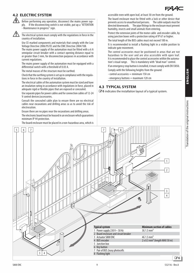
4.2 ELECTRIC SYSTEM
F Before performing any operation, disconnect the mains power sup-ply. If the disconnecting switch is not visible, put up a ''ATTENTION - Maintenance in progress'' sign.
! The electrical system must comply with the regulations in force in the country of installation.
Use CE-marked components and materials that comply with the Low Voltage Directive 2006/95/EC and the EMC Directive 2004/108.The mains power supply of the automation must be fitted with a 6 A omnipolar circuit breaker with a contact opening distance equal to or greater than 3 mm, for disconnection purposes in accordance with current regulations.
The mains power supply of the automation must be equipped with a differential switch with a threshold of 0.03 A.
The metal masses of the structure must be earthed.
Check that the earthing system is set up in compliance with the regula-tions in force in the country of installation.
The electrical cables of the automation system must be sized and have an insulation rating in accordance with regulations in force, placed in adequate rigid or flexible pipes that are exposed or concealed.
Use separate pipes for power cables and for connection cables of 12-24 V control devices/accessories.
Consult the concealed cable plan to ensure there are no electrical cables near excavations and drilling areas so as to avoid the risk of electrocution.
Ensure there are no pipes near the excavations and drilling areas.
The electronic board must be housed in an enclosure which guarantees minimum IP 44 protection.
The board enclosure must be placed in a non-hazardous area, which is
Typical system Minimum section of cables1 Power supply 230 V~ 50 Hz 3G 1.5 mm²2 Board enclosure and circuit breaker3 Actuator S800 ENC 4G 1.5 mm²4 BUS encoder 2 x 0.5 mm² (length MAX 50 m)5 Junction box6 Key button 7 Pair of BUS 2easy photocells8 Flashing light
accessible even with open leaf, at least 30 cm from the ground.
The board enclosure must be fitted with a lock or other device that prevents access to unauthorised persons. The cable outputs must be directed downwards. The pipe fittings to the enclosure must prevent humidity, insects and small animals from entering.
Protect the extension joints of the motor cable and encoder cable, by using junction boxes with a protection rating of IP 67 or higher.
The total length of the BUS cables must not exceed 100 m.
It is recommended to install a flashing light in a visible position to indicate gate movement.
The control accessories must be positioned in areas that are not hazardous to the user and are also accessible with open leaf.It is recommended to place the control accessories within the automa-tion's visual range. This is mandatory with "dead man" control.
If an emergency stop button is installed, it must comply with EN13850.
Comply with the following heights from the ground:
- control accessories = minimum 150 cm
- emergency buttons = maximum 120 cm
4.3 TYPICAL SYSTEM6 indicates the installation layout of a typical system.
7
S800 ENC 10 532116 - Rev.A
Ø MAX 35 mm
Ø MAX 50 mm
Tran
slatio
n of
the
orig
inal
inst
ruct
ions
ENGLIS
H
! Installation must be carried out in compliance with Standards EN 12453 and EN 12445.
Close off the work site and prevent access/transit.
5.1 REQUIRED TOOLS
5. INSTALLATION
6 Symbols: work equipment (type and size)
7-8-12
HEX WRENCH of the specified size (7, 8, 12)
5
CROSS-HEAD SCREWDRIVER of the specified size (6, 8...)
LEVEL
WELDER
x.x Nm
INSTRUMENT with TORQUE ADJUSTMENT - if required for safety, a tool is indicated with torque adjustment and the TIGHTENING TORQUE value. E.g.: HEX WRENCH 6 set at 2.5 Nm
6
2.5 Nm
5.2 REMOVE THE LEAF AND LOWER HINGEIf you automate an existing gate, the leaf must be dismantled and the lower hinge removed before installing the actuator.RISKS
PERSONAL PROTECTIVE EQUIPMENT
! Anchor the leaf to the lifting device with a rope or a suitable chain.
After removing the leaf, place it on the ground or anchor it with a rope
or chain to prevent it from tipping over.
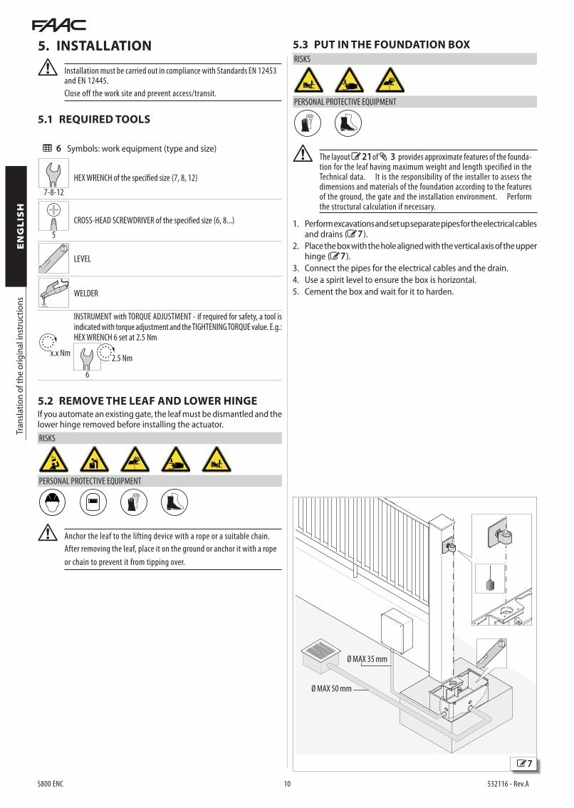
5.3 PUT IN THE FOUNDATION BOX
RISKS
PERSONAL PROTECTIVE EQUIPMENT
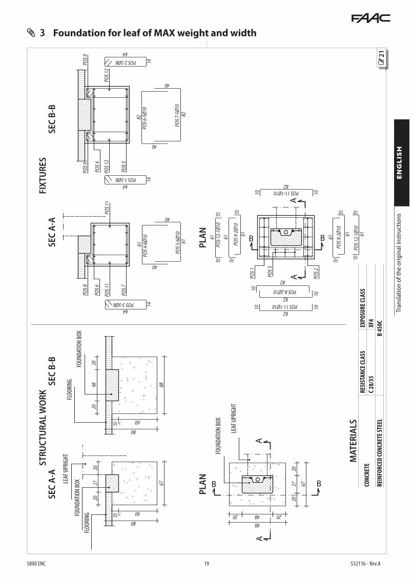
! The layout 21 of 3provides approximate features of the founda-tion for the leaf having maximum weight and length specified in the Technical data. It is the responsibility of the installer to assess the dimensions and materials of the foundation according to the features of the ground, the gate and the installation environment. Perform the structural calculation if necessary.
1. Perform excavations and set up separate pipes for the electrical cables and drains (7 ).
2. Place the box with the hole aligned with the vertical axis of the upper hinge (7 ).
3. Connect the pipes for the electrical cables and the drain.4. Use a spirit level to ensure the box is horizontal.5. Cement the box and wait for it to harden.

9
10
8
S800 ENC 11 532116 - Rev.A
1
3
2
3
= =
41
2
Tran
slatio
n of
the
orig
inal
inst
ruct
ions
ENGLIS
H
5.4 SET UP THE GUIDE BRACKET
RISKS
PERSONAL PROTECTIVE EQUIPMENT
! The guide bracket is an important component for installation safety, to guarantee the stability and control of the leaf during movement.
The guide bracket in the FAAC catalogue is designed for applications with leaves up to the maximum weight and length indicated in the Technical data.
When FAAC guide brackets are not used, the installer is responsible for designing the bracket suitable for the applied loads, defining the construction materials, thicknesses, sizes and surface anti-corrosion treatments. Play between the leaf and bracket must be MAX 2 mm.
The welds made must be certified.
1. Set up the guide bracket (8 -1).2. Position the grooved joint (8 -2).
The notch on the joint must be centred with the centreline of the bracket and directed as shown in the figure.
When the bracket is placed on the box the joint must be centred on the vertical rotation axis of the leaf (8 - 3).
3. Weld the entire circumference of the joint on the guide bracket (8 -4).
5.5 INSTALLING THE LEAF
RISKS
PERSONAL PROTECTIVE EQUIPMENT
1. Assemble the bush (9 -1) in the foundation box, inserted in the reference pin (9 -2).
2. Assemble the guide bracket (9 -3).3. Assemble the leaf on the guide bracket (10 ) and anchor the
leaf to the upper hinge.
! Play between the leaf and bracket must be MAX 2 mm.
DO NOT weld the guide bracket to the leaf.
4. Check that: - the leaf resting on the bracket is perfectly horizontal (use the
spirit level) - movement is smooth and with no friction along the entire stroke,
all the way to the external opening/closing stops (if present)
! When moving it manually, slowly guide the leaf for its entire stroke, do not push the leaf so it moves freely.
11
12
13 14
S800 ENC 12 532116 - Rev.A
2
1
1
3
α αα α
8
2
Tran
slatio
n of
the
orig
inal
inst
ruct
ions
ENGLIS
H
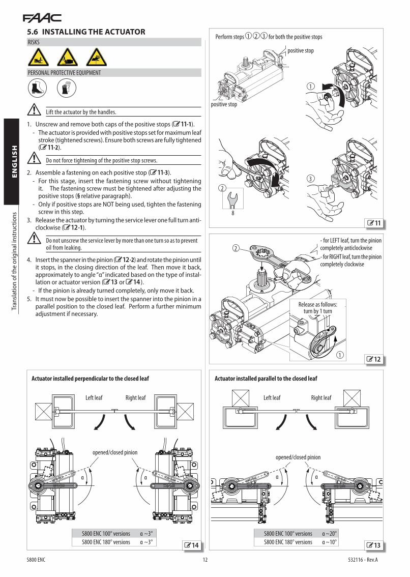
5.6 INSTALLING THE ACTUATOR
RISKS
PERSONAL PROTECTIVE EQUIPMENT
! Lift the actuator by the handles.
1. Unscrew and remove both caps of the positive stops (11 -1). - The actuator is provided with positive stops set for maximum leaf
stroke (tightened screws). Ensure both screws are fully tightened (11 -2).
! Do not force tightening of the positive stop screws.
2. Assemble a fastening on each positive stop (11 -3). - For this stage, insert the fastening screw without tightening
it. The fastening screw must be tightened after adjusting the positive stops (§ relative paragraph).
- Only if positive stops are NOT being used, tighten the fastening screw in this step.
3. Release the actuator by turning the service lever one full turn anti-clockwise (12 -1).
! Do not unscrew the service lever by more than one turn so as to prevent oil from leaking.
4. Insert the spanner in the pinion (12 -2) and rotate the pinion until it stops, in the closing direction of the leaf. Then move it back, approximately to angle “α” indicated based on the type of instal-lation or actuator version (13 or 14 ). - If the pinion is already turned completely, only move it back.
5. It must now be possible to insert the spanner into the pinion in a parallel position to the closed leaf. Perform a further minimum adjustment if necessary.
Left leafLeft leaf Right leafRight leaf
Actuator installed perpendicular to the closed leaf Actuator installed parallel to the closed leaf
Perform steps 1 2 3 for both the positive stops
S800 ENC 100° versions α ~20° S800 ENC 180° versions α ~10°
opened/closed pinionopened/closed pinion
- for LEFT leaf, turn the pinion completely anticlockwise
- for RIGHT leaf, turn the pinion completely clockwise
S800 ENC 100° versions α ~3° S800 ENC 180° versions α ~3°
Release as follows:turn by 1 turn
positive stop
positive stop
15
16
S800 ENC 13 532116 - Rev.A
2
M12
5
12
100 Nm
6
1
3
8
1
7
2
B
A
1 2
4
3
Tran
slatio
n of
the
orig
inal
inst
ruct
ions
ENGLIS
H
Left leaf Right leaf
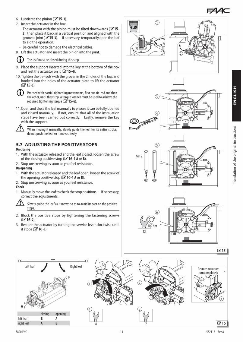
6. Lubricate the pinion (15 -1).7. Insert the actuator in the box.
- The actuator with the pinion must be tilted downwards (15 -2), then place it back in a vertical position and aligned with the grooved joint (15 -3). If necessary, temporarily open the leaf to aid the operation.
- Be careful not to damage the electrical cables.8. Lift the actuator and insert the pinion into the joint.
The leaf must be closed during this step.
9. Place the support inserted into the key at the bottom of the box and rest the actuator on it (15 -4).
10. Tighten the tie-rods with the grover in the 2 holes of the box and hooked into the holes of the actuator plate to lift the actuator (15 -5).
Proceed with partial tightening movements, first one tie-rod and then the other, until they stop. A torque wrench must be used to achieve the required tightening torque (15 -6).
11. Open and close the leaf manually to ensure it can be fully opened and closed manually. If not, ensure that all of the installation steps have been carried out correctly. Lastly, remove the key with the support.
! When moving it manually, slowly guide the leaf for its entire stroke, do not push the leaf so it moves freely.
5.7 ADJUSTING THE POSITIVE STOPSOn closing
1. With the actuator released and the leaf closed, loosen the screw of the closing positive stop (16 -1 A or B).
2. Stop unscrewing as soon as you feel resistance. On opening
1. With the actuator released and the leaf open, loosen the screw of the opening positive stop (16 -1 A or B).
2. Stop unscrewing as soon as you feel resistance.Check
1. Manually move the leaf to check the stop positions. If necessary, correct the adjustments.
! Slowly guide the leaf as it moves so as to avoid impact on the positive stops.
2. Block the positive stops by tightening the fastening screws (16 -2).
3. Restore the actuator by turning the service lever clockwise until it stops (16 -3).
Restore actuator:turn completely
closing opening
left leaf B A
right leaf A B

17
18
S800 ENC 14 532116 - Rev.A
8
a
a
b
b
AB
1
Tran
slatio
n of
the
orig
inal
inst
ruct
ions
ENGLIS
H
RISKS
PERSONAL PROTECTIVE EQUIPMENT
F Before setting up electrical connections, disconnect the power supply of the automation. If the disconnecting switch is not visible, put up a ''ATTENTION - Maintenance in progress'' sign.
1. Set up the electrical connections according to the instructions of the electronic control board and the installed accessories.
Electric motor cable
yellow-green earth
blue neutral
brown phase 1
black phase 2
2. Turn the mains power supply back on.3. Switch the electronic board on according to the specific instruc-
tions. If the motor rotates the wrong way, disconnect the power and swap the wires of phases 1 and 2.
6.1 FORCE ADJUSTMENT (BY-PASS)
RISKS
PERSONAL PROTECTIVE EQUIPMENT
! Adjust the by-passes in accordance with the applicable standards (EN 12445).
1. Remove the protective caps (17 -1).2. Adjust the opening and closing force by actuating the automation
electrically and using the by-pass screw corresponding to the manoeuvre in progress (17 A or B):
screw A = adjusts the force of clockwise leaf movement
screw B = adjusts the force of anticlockwise leaf movement
tighten to increase the force +
loosen to decrease the force –
3. Set the protective caps back in place (17 -1).
CLOSURE OF THE BOX
Close the cover of the box with the supplied screws (18 ).
6.2 FINAL OPERATIONS1. Ensure that the forces generated by the leaf are within the limits
allowed by the standard. Use an impact curve gauge in ac-cordance with standards EN 12453 and EN 12445. For countries outside the EU, when there is no specific local standard, the force must be less than 150 N static.
2. Ensure that the maximum manual moving force of the leaf is less than 220 N.
3. Use appropriate signs to highlight the areas where residual risks remain despite having implemented all safety measures.
4. Put up the ''DANGER: AUTOMATIC MOVEMENT'' sign on the gate
6. START-UP
SCREW
A adjusts the force of clockwise leaf movement (a)
B adjusts the force of anticlockwise leaf movement (b)
ADJUSTMENT
+ tighten to increase the force
– loosen to decrease the force
in a visible position.5. Put up the CE marking on the gate.6. Complete the EC Declaration of Conformity of the machine and
the system Logbook.7. Provide the owner/operator of the automation with the EC Decla-
ration, the system Logbook with the maintenance schedule and the user instructions of the automation.
19
S800 ENC 15 532116 - Rev.A
B
A
3
2
1
2
1
Tran
slatio
n of
the
orig
inal
inst
ruct
ions
ENGLIS
H
7. MAINTENANCE
RISKS
PERSONAL PROTECTIVE EQUIPMENT
REQUIRED TOOLS
7.2 OPERATING PROBLEMS
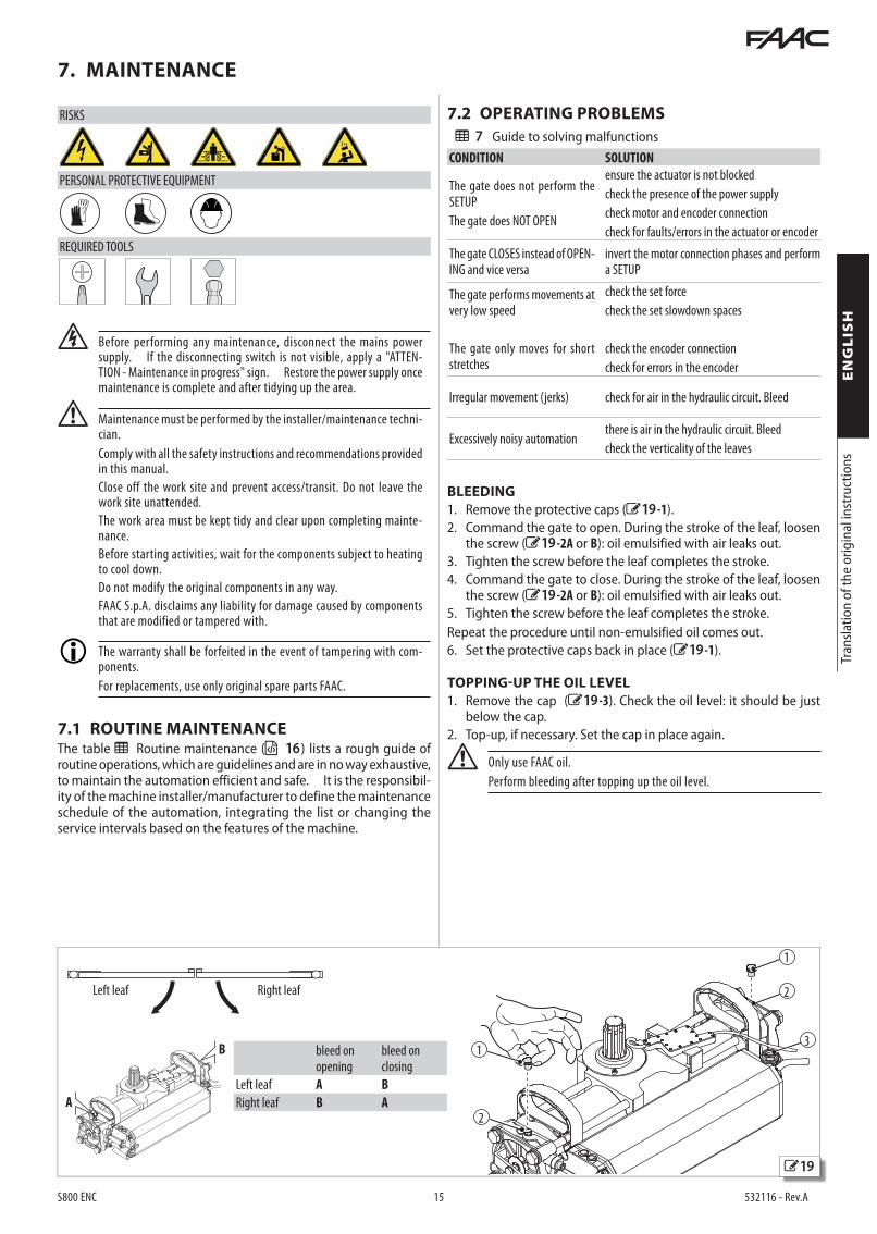
Left leaf Right leaf
bleed on opening
bleed on closing
Left leaf A B
Right leaf B A
7 Guide to solving malfunctionsCONDITION SOLUTION
The gate does not perform the SETUP
The gate does NOT OPEN
ensure the actuator is not blocked
check the presence of the power supply
check motor and encoder connection
check for faults/errors in the actuator or encoder
The gate CLOSES instead of OPEN-ING and vice versa
invert the motor connection phases and perform a SETUP
The gate performs movements at very low speed
The gate only moves for short stretches
check the set force
check the set slowdown spaces
check the encoder connection
check for errors in the encoder
Irregular movement (jerks) check for air in the hydraulic circuit. Bleed
Excessively noisy automationthere is air in the hydraulic circuit. Bleed
check the verticality of the leaves
BLEEDING
1. Remove the protective caps (19 -1).2. Command the gate to open. During the stroke of the leaf, loosen
the screw (19 -2A or B): oil emulsified with air leaks out.3. Tighten the screw before the leaf completes the stroke.4. Command the gate to close. During the stroke of the leaf, loosen
the screw (19 -2A or B): oil emulsified with air leaks out.5. Tighten the screw before the leaf completes the stroke.Repeat the procedure until non-emulsified oil comes out.6. Set the protective caps back in place (19 -1).
TOPPING-UP THE OIL LEVEL
1. Remove the cap (19 -3). Check the oil level: it should be just below the cap.
2. Top-up, if necessary. Set the cap in place again.
! Only use FAAC oil.
Perform bleeding after topping up the oil level.
F Before performing any maintenance, disconnect the mains power supply. If the disconnecting switch is not visible, apply a "ATTEN-TION - Maintenance in progress" sign. Restore the power supply once maintenance is complete and after tidying up the area.
! Maintenance must be performed by the installer/maintenance techni-cian.
Comply with all the safety instructions and recommendations provided in this manual.
Close off the work site and prevent access/transit. Do not leave the work site unattended.
The work area must be kept tidy and clear upon completing mainte-nance.
Before starting activities, wait for the components subject to heating to cool down.
Do not modify the original components in any way.
FAAC S.p.A. disclaims any liability for damage caused by components that are modified or tampered with.
The warranty shall be forfeited in the event of tampering with com-ponents.
For replacements, use only original spare parts FAAC.
7.1 ROUTINE MAINTENANCE The table Routine maintenance ( 16 ) lists a rough guide of routine operations, which are guidelines and are in no way exhaustive, to maintain the automation efficient and safe. It is the responsibil-ity of the machine installer/manufacturer to define the maintenance schedule of the automation, integrating the list or changing the service intervals based on the features of the machine.

S800 ENC 16 532116 - Rev.A
Tran
slatio
n of
the
orig
inal
inst
ruct
ions
ENGLIS
H
8 Routine maintenanceIf the checks listed below reveal conditions other than those foreseen, they must be restored.Operations FrequencyStructures
Check the structure that the gate, plinth and building/fencing parts adjacent to the automation are fastened to: absence of damage, cracks, fractures, failures.
12
Check the movement area of the gate: absence of obstacles, absence of objects/deposits which reduce safety clearances.
12
Check the absence of hooking points or dangerous prongs. 12
Gate
Check the gate and its fastenings: integrity, no deformations or rust, etc.
Check the correct tightening of screws and bolts.12
Check the concentricity between the upper hinge of the leaf and the lower rota-tion fulcrum provided by the foundation box.
12
Check hinges and bearings: integrity, perfectly positioned and fastened in place, no deformation, rust, etc.
12
Lubricate hinges and/or bearings if necessary. 12
Check the mechanical stops: fastening and solidity. Both sides must be checked, simulating the impact that they could undergo during use.
12
Check the guide bracket of the leaf: integrity, absence of deformation and rust, proper fastening, etc.
Check the absence of wear/collapsing which could jeopardise the condition that all the weight of the leaf bears on the lower rotation fulcrum.
12
Check the anti-falling device: fastening and integrity. 12
General cleaning of the gate operating area. 12
Actuator
Check the integrity and correct fastening. 12
Check the sturdiness of the connections of the actuator to the leaf to avoid uncontrolled movements of the leaf should it break.
Check the welding of the joint on the guide bracket.
12
Check reversibility and irreversibility. 12
Check that there is no oil leakage. 12
Top up the oil level, if necessary. Only use FAAC oil. 12
Bleed the oil, if necessary. 12
Clean the actuator and the foundation box
Check drainage efficiency.12
Check the integrity of the actuator cables, of the cable glands and of the junc-tion boxes.
12
Electronic equipment
Check the integrity of the electronic board enclosure. 12
Check the integrity of the power and connection cables and of the cable glands.
Check the integrity of the connectors and of the wiring.12
Check that there are no signs of overheating, burns, etc. on electronic components. 12
Check the integrity and proper operation of the limit switches, if used. 12
Check the integrity of the earthing connections. 12
Check proper operation of the circuit breaker and residual current device. 12
Control devices
Check the integrity and proper operation of the installed devices and of the remote controls.
12
Sensitive edges
Check: integrity, fastening and proper operation. 6
Deformable edges
Check: integrity and fastening. 12
Photocells
Check: integrity, fastening and proper operation. 6
Check the columns: integrity, fastening, no deformation, etc. 6
Flashing light
Check: integrity, fastening and proper operation. 12
Electric locks
Check: integrity, fastening and proper operation.
Clean the insertion seats.12
Access control
Check that the gate opens correctly only with authorised user recognition. 12
Complete automation
Check that the automation works properly, according to the programmed logic, using the various control devices.
12
Check that the gate moves correctly, smoothly and regularly without any strange noise.
Check its correct opening and closing speed and that it follows the intended slowdowns.
12
Check proper operation of the manual release: when the release is activated, the gate should only be able to be moved manually.
Check the presence of lock caps.
6
Ensure that the maximum manual moving force of the leaf is less than 220 N. 6
Check the proper operation of the safety edges for obstacle detection. 6
Check the proper operation of the encoder for obstacle detection. 6
Check the proper operation of each pair of photocells. 6
Check that there is no optical/luminous interference between the pairs of photocells.
6
Check the limitation curve of the forces (standards EN 12453 and EN 12445). For countries outside the EU, when there is no specific local standard, the force must be less than 150 N static.
6
Check the presence, integrity and legibility of all the necessary signs: residual risks, exclusive use, etc.
12
Check the presence, integrity and legibility of the CE marking of the gate and of the DANGER AUTOMATIC MOVEMENT warning sign.
12
20
S800 ENC 17 532116 - Rev.A
1
2 3Tr
ansla
tion
of th
e or
igin
al in
stru
ctio
nsENGLIS
H
8.1 SAFETY RECOMMENDATIONSSystems set up with FAAC S800 ENC series underground actuators are intended for vehicle transit.The user must be in good physical and mental condition, aware of and responsible for the hazards that may be generated when using the product.
! - Do not pass and/or stop within the automation's range of action while it is moving.
- Do not use the automation when its range of action is not clear of people, animals or objects.
- Do not allow children to come close or play near the automation's range of action.
- Do not obstruct the movement of the automation.
- Do not climb onto, hold onto or be pulled by the leaf.
- Do not allow the control devices to be used by persons who are not specifically authorised and trained.
- Do not allow the control devices to be used by children or persons with reduced mental-physical abilities, unless under the supervision of an adult responsible for their safety.
- Do not use the automation with movable and/or fixed guards that have been tampered with or removed.
- Do not use the automation with faults/tampering which could jeopardise safety.
- Do not expose the automation to aggressive chemical or environ-mental agents; do not expose the actuator to direct water jets of any type or amount.
- Do not expose the automation to flammable gases or fumes.
- Do not perform any operation on the automation components.
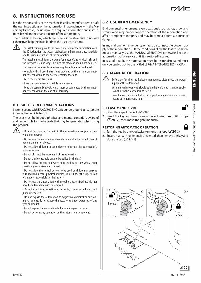
8.3 MANUAL OPERATION
! Before performing the Release manoeuvre, disconnect the power supply of the automation.
With manual movement, slowly guide the leaf along its entire stroke. Do not push the leaf so it runs freely.
Do not leave the gate unlocked: after performing manual movement, restore automatic operation.
RELEASE MANOEUVRE
1. Open the cap of the lock (20 -1).2. Insert the key and turn it one anti-clockwise turn until it stops
(20 -2), then move the gate manually.
RESTORING AUTOMATIC OPERATION
1. Turn the key by one clockwise turn until it stops (20 -3).2. Ensure manual movement is prevented, then remove the key and
close the cap (20 -1).
8. INSTRUCTIONS FOR USE
Restore
Release
8.2 USE IN AN EMERGENCYIt is the responsibility of the machine installer/manufacturer to draft the user instructions of the automation in accordance with the Ma-chinery Directive, including all the required information and instruc-tions based on the characteristics of the automation.The guidelines below, which are purely indicative and in no way exhaustive, help the installer draft the user instructions.
! The installer must provide the owner/operator of the automation with the EC Declaration, the system Logbook with the maintenance schedule and the user instructions of the automation.
The installer must inform the owner/operator of any residual risks and the intended use and ways in which the machine should not be used.
The owner is responsible for operating the automation and must:
- comply with all User instructions provided by the installer/mainte-nance technician and the Safety recommendations
- keep the user instructions
- have the maintenance schedule implemented
- keep the system Logbook, which must be completed by the mainte-nance technician at the end of all servicing
In any malfunction, emergency or fault, disconnect the power sup-ply of the automation. If the conditions allow the leaf to be safely moved manually, use the MANUAL OPERATION; otherwise, keep the automation out of service until it is restored/repaired.In case of a fault, the automation must be restored/repaired must only be carried out by the INSTALLER/MAINTENANCE TECHNICIAN.
Environmental phenomena, even occasional, such as ice, snow and strong wind may hinder correct operation of the automation and affect component integrity and may become a potential source of danger.
S800 ENC 18 532116 - Rev.A
Tran
slatio
n of
the
orig
inal
inst
ruct
ions
ENGLIS
H
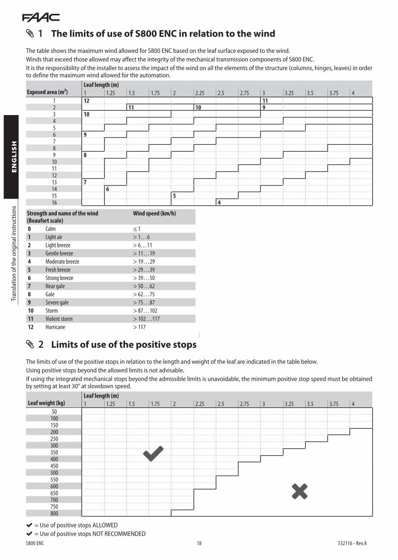
1 The limits of use of S800 ENC in relation to the wind
The table shows the maximum wind allowed for S800 ENC based on the leaf surface exposed to the wind.Winds that exceed those allowed may affect the integrity of the mechanical transmission components of S800 ENC.It is the responsibility of the installer to assess the impact of the wind on all the elements of the structure (columns, hinges, leaves) in order to define the maximum wind allowed for the automation.
Exposed area (m²)Leaf length (m)
1 1.25 1.5 1.75 2 2.25 2.5 2.75 3 3.25 3.5 3.75 4
1 12 112 11 10 93 10456 9789 8
10111213 714 615 516 4
Strength and name of the wind(Beaufort scale)
Wind speed (km/h)
0 Calm ≤ 1
1 Light air > 1…6
2 Light breeze > 6…11
3 Gentle breeze > 11…19
4 Moderate breeze > 19…29
5 Fresh breeze > 29…39
6 Strong breeze > 39…50
7 Near gale > 50…62
8 Gale > 62…75
9 Severe gale > 75…87
10 Storm > 87…102
11 Violent storm > 102…117
12 Hurricane > 117
2 Limits of use of the positive stops
The limits of use of the positive stops in relation to the length and weight of the leaf are indicated in the table below.Using positive stops beyond the allowed limits is not advisable.If using the integrated mechanical stops beyond the admissible limits is unavoidable, the minimum positive stop speed must be obtained by setting at least 30° at slowdown speed.
Leaf weight (kg)Leaf length (m)
1 1.25 1.5 1.75 2 2.25 2.5 2.75 3 3.25 3.5 3.75 4
50100150200250300350400450500550600650700750800
= Use of positive stops ALLOWED = Use of positive stops NOT RECOMMENDED
21
S800 ENC 19 532116 - Rev.A
AA
BB
AA
BB
82 82
40
40
61 61
40
40
61
10
61
10
82
10
82 10
61
10
61
10
61
10
82 10
82
1010
10
1061
10
10
64 14
64
14
64 14
>10
>10
60
2027
20
67
80
2048
20
8860
80
20 48 2088
2027
20
67
POS 4
-6Ø1
0
POS 5
-6Ø1
0
POS 6
-5Ø1
0
POS 7
-5Ø1
0
POS 1-5Ø8
POS 8-2Ø10
POS 9
-2Ø1
0
POS 1
2-1Ø
10
POS 11-1Ø10
POS 2-5Ø8
POS 3-5Ø8
POS 1
POS 3
POS 2
POS 6
POS 7
POS 1
1PO
S 11
POS 4
POS 1
2
POS 5
POS 1
2
POS 8
POS 9
POS 9
POS 11-1Ø10
POS 9
-2Ø1
0
POS 1
2-1Ø
10
Tran
slatio
n of
the
orig
inal
inst
ruct
ions
ENGLIS
H
STRU
CTU
RAL
WO
RK
MAT
ERIA
LSCO
NCR
ETE
RES
ISTA
NCE
CLA
SSEX
PO
SUR
E CL
ASS
C 28
/35
XF4
REI
NFO
RCE
D C
ON
CRET
E ST
EEL
B 4
50C
FIXT
URE
SSE
C A-
ASE
C B-
BSE
C A-
ASE
C B-
BLE
AF U
PRIG
HT
LEAF
UPR
IGH
T
FLOO
RIN
G
FOU
NDA
TION
BOX
FOU
NDA
TION
BOX
FOU
NDA
TION
BOX
FLOO
RIN
G
PLAN
PLAN
3 Foundation for leaf of MAX weight and width

S800 ENC 20 532116 - Rev.A

S800 ENC 21 532116 - Rev.A

FAAC S.p.A. Soc. Unipersonale
Via Calari, 10 - 40069 Zola Predosa BOLOGNA - ITALY
Tel. +39 051 61724 - Fax +39 051 758518
www.faac.it - www.faacgroup.com
S800 ENC 22 532116 - Rev.A


