3.1 Internal Mechanical Positive Stops 103.2 Adjustment Of The Travel-Limit Stops 103.3 Final Steps 10
4. MANUAL OPERATIONS 11
4.1 Built In Hydraulic Release 114.2 External In Hydraulic Release 11
5. MAINTENANCE 12
5.1 Bleeding Operations 12
6. ENCODER CONNECTION 13
7. S800H PARTS DIAGRAMS 14
E024U CONTROL BOARD 16
TABLE OF CONTENTS
S800H ENC Rev. B September 2016
3
1. Install the gate operator only when the following conditions have been met:
• The operator is appropriate for the type and usage class of the gate.
• All openings of a horizontal slide gate have been guarded or screened from the bottom of the gate to a minimum of 4 feet (1.25 m) above the ground to prevent a 2.25 inch (55 mm) diameter sphere from passing through openings anywhere in the gate or through that portion of the adjacent fence that the gate covers when in the open position.
• All exposed pinch points are eliminated or guarded.
• Guarding is supplied for exposed rollers.
2. The operator is intended for installation on gates used by vehicles only. Pedestrians must be provided with a separate access opening.
3. To reduce the risk of entrapment when opening and closing, the gate must be installed in a location that allows adequate clearance between the gate and adjacent structures. Swinging gates shall not open outward into public access areas.
4. Before installing the gate operator, ensure that the gate has been properly installed and that it swings freely in both directions. Do not over-tighten the operator clutch or pressure relief valve to compensate for a damaged gate.
5. User controls must be installed at least 6 feet (1.83 m) away from any moving part of the gate and located where the user is prevented from reaching over, under, around or through the gate to operate the controls. Controls located outdoors or those that are easily accessible shall have security features to prevent unauthorized use.
6. The Stop and/or Reset buttons must be located within line-of-sight of the gate. Activation of the reset control shall not cause the operator to start.
7. All warning signs and placards must be installed and easily seen within visible proximity of the gate. A minimum of one warning sign shall be installed on each side of the gate.
8. For gate operators that utilize a non-contact sensor (photo beam or the like):
• See instructions on the placement of non-contact sensors for each type of application.
• Exercise care to reduce the risk of nuisance tripping, such as when a vehicle trips the sensor while the gate is still moving.
• Locate one or more non-contact sensors where the risk of entrapment or obstruction exists, such as at the reachable perimeter of a moving gate or barrier.
• Use only “FAAC Photobeam” or “EMX IRB-RET” photo-electric eyes to comply with UL325.
Important Installation Instructions
WARNING - TO REDUCE THE RISK OF SEVERE INJURY OR DEATH:
• READ AND FOLLOW ALL INSTRUCTIONS.
• Never let children operate or play with the gate controls. Keep remote controls away from children.
• Always keep people and objects away from the gate. NO ONE SHOULD CROSS THE PATH OF A MOVING GATE.
• Test the gate operator monthly. The gate MUST reverse on contact with a rigid object or when an object activates a non-contact sensor. If necessary, adjust the force or the limit of travel and then retest the gate operator. Failure to properly adjust and retest the gate operator can increase the risk of injury or death.
• Use the manual release mechanism only when the gate is not moving.
• KEEP GATE PROPERLY MAINTAINED. Have a qualified service person make repairs to gate hardware.
• The entrance is for vehicles only. Pedestrians must use a separate entrance.
• SAVE THESE INSTRUCTIONS.
IMPORTANT SAFETY INFORMATION
Important Safety Instructions
4
Gate Construction
Vehicular gates should be constructed and installed in accordance with ASTM F2200: Standard Specification for Automated Vehicular Gate Construction.
For more information, contact ASTM at: www.astm.org
Installation
• If you have any questions or concerns regarding the safety of the gate operating system, do not install the operator and consult the manufacturer.
• The condition of the gate structure itself directly affects the reliability and safety of the gate operator.
• Only qualified personnel should install this equipment. Failure to meet this requirement could cause severe injury and/or death, for which the manufacturer cannot be held responsible.
• The installer must provide a main power switch that meets all applicable safety regulations.
• It is extremely unsafe to compensate for a damaged gate by increasing hydraulic pressure.
• Install devices such as reversing edges and photo beams to provide better protection for personal property and pedestrians. Install reversing devices that are appropriate to the gate design and application.
• Before applying electrical power, ensure that voltage requirements of the equipment correspond to the supply voltage. Refer to the label on your gate operator system.
Usage
• Use this equipment only in the capacity for which it was designed. Any use other than that stated should be considered improper and therefore dangerous.
• The manufacturer cannot be held responsible for damage caused by improper, erroneous or unreasonable use.
• If a gate system component malfunctions, disconnect the main power before attempting to repair it.
• Do not impede the movement of the gate, you may injure yourself or damage the gate system as a result.
• This equipment may reach high thermal temperatures during normal operation, therefore use caution when touching the external housing of the gate operator.
• Use the manual release mechanism according to the procedures presented in this manual.
• Before performing any cleaning or maintenance operations, disconnect power to the equipment.
• All cleaning, maintenance or repair work must performed by qualified personnel.
General Safety Precautions
9. For gate operators that utilize a contact sensor (edge sensor or similar):
• Locate one or more contact sensors where the risk of entrapment or obstruction exists, such as at the leading edge, trailing edge, and post mounted both inside and outside of a vehicular horizontal slide gate
• Locate one or more contact sensors at the bottom edge of a vehicular vertical lift gate.
• Locate one or more contact sensors at the bottom edge of a vertical barrier (arm).
• Locate one or more contact sensors at the pinch point of a vehicular vertical pivot gate.
• Locate hard-wired contact sensors and wiring so that communication between sensor and gate operator is not subjected to mechanical damage.
• Locate wireless contact sensors, such as those that transmit radio frequency (RF) signals, where the transmission of signals are not obstructed or impeded by building structures, natural land-scaping or similar hindrances. Wireless contact sensors shall function under their intended end-use conditions.
• Use only FAAC MSE MO, CN60 or M60 edge sensors.
Important Installation Instructions (continued)
5
RESIDENTIAL VEHICULAR GATE OPERATOR CLASS I
A vehicular gate operator system intended for use in a single family dwelling, garage or associated parking area.
UL325 Gate Operator Classifications
COMMERCIAL / GENERAL ACCESS VEHICULAR GATE OPERATOR CLASS II
A vehicular gate operator system intended for use in commercial locations or buildings such as multi-family housing units (five or more single family units), hotels, parking garages, retail stores or other buildings that service the general public.
INDUSTRIAL / LIMITED ACCESS VEHICULAR GATE OPERATOR CLASS III
A vehicular gate operator system intended for use in industrial locations or buildings such as factories, loading docks or other locations not intended to service the general public.
RESTRICTED ACCESS VEHICULAR GATE OPERATOR CLASS IV
A vehicular gate operator system intended for use in guarded industrial locations or buildings such as airport security areas or other restricted access locations that do not service the general public, and in which unauthorized access is prevented via supervision by security personnel.
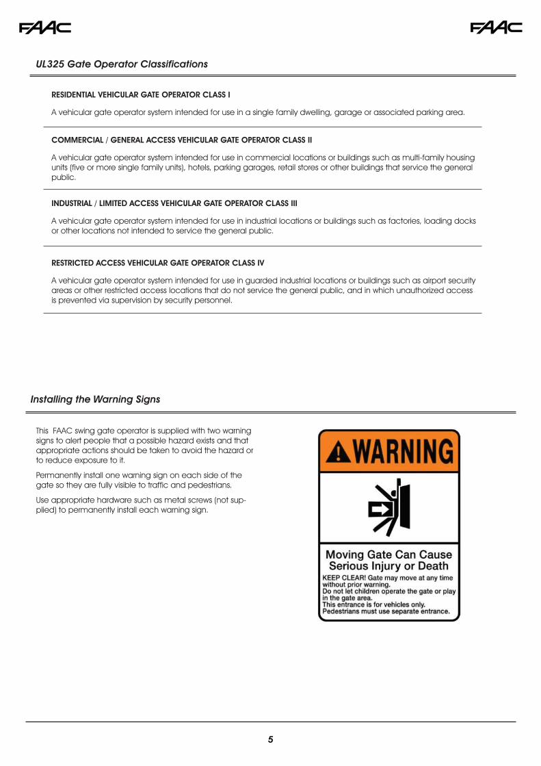
This FAAC swing gate operator is supplied with two warning signs to alert people that a possible hazard exists and that appropriate actions should be taken to avoid the hazard or to reduce exposure to it.
Permanently install one warning sign on each side of the gate so they are fully visible to traffic and pedestrians.
Use appropriate hardware such as metal screws (not sup-plied) to permanently install each warning sign.
Installing the Warning Signs
1 34
56 7
8
9
16
17
18
5
4
211
12
13
14
15
10
14
11
11
1
2
15
1 S800H ENC Operators 2 x AWG 14 (max 30’) AWG 12 (max 50’) AWG 10 (max 100’) AWG 20 for encoder bus (Max. length 100’)2 Photocells AWG 20 (Max. length 100’)3 Control unit AWG 14 for AC power4 Key operated push-button AWG 20
1. DESCRIPTION AND TECHNICAL SPECIFICATIONSThe FAAC S800H ENC is an integrated automatic in-ground gate operator for a swinging gate leaf. It makes possible to automate gates without altering their appearance. The opera-tor iinclude the hydraulic control unit (pump) and the hydraulic drive unit in the same body. The model with a hydraulic lock
Fig.1
1 Bleed screw2 Support handle3 Pinion4 Mounting bolts5 Travel-limit adjustment nut6 Hydraulic release7 Oil filling plug8 Motor Cover9 Electronic encoder10 Foundation box11 Holes for securing the cover12 Slots for securing the jack13 Bushing14 Wings for concrete pad grip15 Power cable or drain pipe routing holes16 Plastic adjustment wrench and support bushing17 Foundation box cover18 Splined shaft collar
S800H ENC OPERATORdevice (CBAC) does not require the installation of an electri-cal lock, as it guarantees the mechanical locking of the leaf when the motor is not operating. The model without a hydrau-lic lock device (SBW) requires an electrical locks to ensure that the leaf is mechanically locked.
The S800H ENC operator is designed and manufactured to automate swing leaf gates. Do not use for any other purpose.
TECHNICALSPECIFICATIONS
CBACOPERATOR
SBWOPERATOR
Power supply 24 Vdc
Power 60 W
Current 7 A
Protection class IP 67
Operating ambient temperature 4°F +131°F (-20 °C +55°C)
The installer is responsible for providing the main power breaker switch, and for making sure that the entire gate system meets all applicable local electrical codes.
Make sure to locate all controls that operate the gate system at least 6 ft away from any moving parts.
6
1 1/2
10
22 7/8=
=
14 3/16
2 1/4
2
3 4
5
1
10 5/8
18 7/8
9 13/16
1 27/32 Drain
6
7
Dimensions in inches Dimensions in inches
Dimensions in inches Dimensions in inches
Dimensions in inches
2
2. INSTALLATION OF THE SUPPORT BOX
TO ENSURE A CORRECT INSTALLATION, THE LEAF ROTATION AXIS MUST BE PERFECTLY ALIGNED WITH THE OPERATOR
7
1x 1
1
A
1 1
B
TRAVEL-LIMIT STOP AT OPENING
TRAVEL-LIMIT STOP AT CLOSING
Fig.6
Fig.4
Fig.5
Fig.3
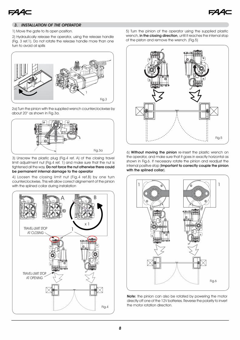
1) Move the gate to its open position.
2) Hydraulically release the operator, using the release handle (Fig. 3 ref.1). Do not rotate the release handle more than one turn to avoid oil spills
3) Unscrew the plastic plug (Fig.4 ref. A) of the closing travel limit adjustment nut (Fig.4 ref. 1) and make sure that the nut is tightened all the way. Do not force the nut otherwise there could be permanent internal damage to the operator
4) Loosen the closing limit nut (Fig.4 ref.B) by one turn counterclockwise. This will allow correct alignement of the pinion with the splined collar during installation
5) Turn the pinion of the operator using the supplied plastic wrench, in the closing direction, until it reaches the internal stop of the piston and remove the wrench. (Fig.5)
3. INSTALLATION OF THE OPERATOR
2a) Turn the pinion with the supplied wrench counterclockwise by about 20° as shown in Fig.3a.
Fig.3a 6) Without moving the pinion re-insert the plastic wrench on the operator, and make sure that it goes in exactly horizontal as shown in Fig.6. If necessary rotate the pinion and readjust the internal positive stop (Important to correctly couple the pinion with the splined collar).
Note: the pinion can also be rotated by powering the motor directly off one of the 12V batteries. Reverse the polarity to invert the motor rotation direction.
8
A B
C
Fig.7
Fig.9
Fig.10
Fig.11
10) Place the supplied plastic wrench with the spacer under the operator, as shown in figure 10 ref. B, C
12) Insert and tighten the fastening long bolts with the supplied lockwasher as shown in Fig. 10 ref. C, in order to secure the operator to the load bearing box as shown in Fig. 11.
13) Close the gate and check if the closing travel-limit stop is correctly positioned; if necessary, adjust the travel-limit stop, referring to the instructions in paragraph 3.2.
14) Open the gate and check if the opening travel-limit stop is correctly positioned; if necessary, adjust the travel-limit stop, referring to the instructions in paragraph 3.2.
15) Hydraulically re-lock the operator
7) Turn the operator pinion with the supplied wrench until it points to the open position (90° from close) and then remove the wrench (see Fig. 7)
Fig.8
8) Grease the pinion and insert the operator in the load bearing box as shown in Fig.8-9,
9) Raise the operator with its handles (Fig.10 ref. A), inserting the pinion in the splined collar of the load bearing box. To facilitate the operation, slightly wiggle the operator until coupling takes place.
9
1
2
A B
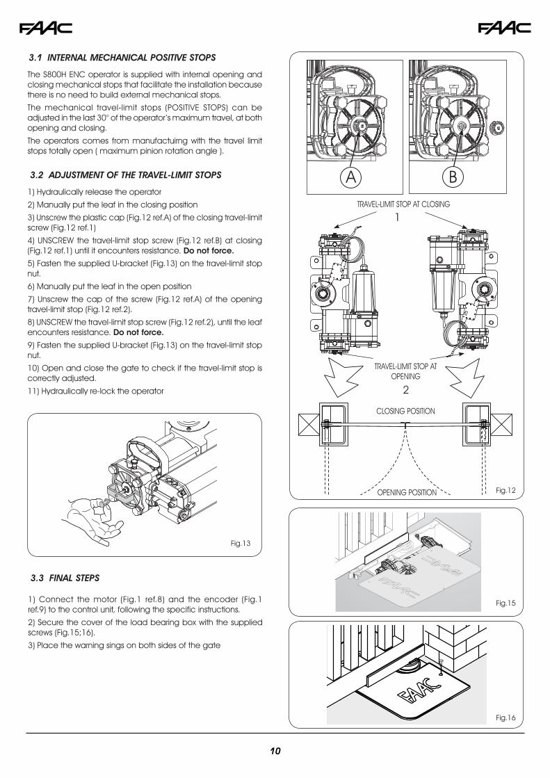
The S800H ENC operator is supplied with internal opening and closing mechanical stops that facilitate the installation because there is no need to build external mechanical stops.
The mechanical travel-limit stops (POSITIVE STOPS) can be adjusted in the last 30° of the operator’s maximum travel, at both opening and closing.
The operators comes from manufactuirng with the travel limit stops totally open ( maximum pinion rotation angle ).
TRAVEL-LIMIT STOP AT OPENING
TRAVEL-LIMIT STOP AT CLOSING1) Hydraulically release the operator
2) Manually put the leaf in the closing position
3) Unscrew the plastic cap (Fig.12 ref.A) of the closing travel-limit screw (Fig.12 ref.1)
4) UNSCREW the travel-limit stop screw (Fig.12 ref.B) at closing (Fig.12 ref.1) until it encounters resistance. Do not force.
5) Fasten the supplied U-bracket (Fig.13) on the travel-limit stop nut.
6) Manually put the leaf in the open position
7) Unscrew the cap of the screw (Fig.12 ref.A) of the opening travel-limit stop (Fig.12 ref.2).
8) UNSCREW the travel-limit stop screw (Fig.12 ref.2), until the leaf encounters resistance. Do not force.
9) Fasten the supplied U-bracket (Fig.13) on the travel-limit stop nut.
10) Open and close the gate to check if the travel-limit stop is correctly adjusted.
11) Hydraulically re-lock the operator
CLOSING POSITION
OPENING POSITION Fig.12
Fig.15
Fig.16
1) Connect the motor (Fig.1 ref.8) and the encoder (Fig.1 ref.9) to the control unit, following the specific instructions.
2) Secure the cover of the load bearing box with the supplied screws (Fig.15;16).
3) Place the warning sings on both sides of the gate
3.1 INTERNAL MECHANICAL POSITIVE STOPS
3.2 ADJUSTMENT OF THE TRAVEL-LIMIT STOPS
3.3 FINAL STEPS
Fig.13
10
Fastening bolts for the release system
Bleed screws
Fig. 18
Banjo Bolt
Hydraulic Hose
Union bolt
1
Fig. 19
4.2.1 Installation Procedure
2
4.2.2 Bleeding Procedure
The S800H operator kit comes with a field installable hydraulic manual release, that can be conveniently mounted on top of the load bearing box
1. Manually release the operator and make sure it is turned off with the batteries disconnected
2. Remove the vent screws from each flange
3. Spin the set nut all the way onto the union bolt (Fig. 18)
4.Tighten the union bolt into the flange by hand and then snug it down with a 13mm wrench to 20 Nm. This will set the flare of the union bolt into the flare of the flange. Do not overtighten the union bolt as it can permanently damage the flange
5. Next with a wrench still on the union bolt, spin the set nut down by hand and then snug it down to 20 Nm. Reference Fig. 20 for the correct visual of the installed union bolt with set nut.
6. Continue installing the hoses and banjo bolts and then bleed the system as shown in section 4.2.2. Inspect for leaks, if you find any repeat the above steps.
7. Fasten the external release body to the load bearing box system using the two supplied M8 screws (Fig. 19 ref. 1)
< 20 Nm
Fig. 20
The installation of the hydraulic release could have let air in the circuit, causing irregular operation like an incorrect movement of the leaf and excessive noise during operation.
To correct this problem, operate as follows:
1) Command an opening movement of the gate.
2) During the leaf movement, loosen the opening bleed screw (Fig.21 ref.1 )
Set nut
If the gate must be moved manually due to a power failure or operator’s malfunction you can use the built in hydraulic release device with the release handle (Fig.17):
1) Remove the cover from the load bearing box.
2) Turn the release handle:
- To release, turn the hanlde counter-clockwise by one turn. (Do not completely unfasten the screw to avoid oil spills)
- To re-engage the hydraulic operation, turn the screw clockwise up to the mechanical stop point. (Do not overtighten)
Fig.17
4.1 BUILT IN HYDRAULIC RELEASE
4.2 EXTERNAL HYDRAULIC RELEASE
4. MANUAL OPERATION
RIGHT WRONG
11
Fig. 21
1 - opening direction
2 - closing direction
To release the operator, remove the plastic cover, insert the key and turn the release lock counter-clockwise for about one turn. (Fig. 23 ref. 1)To re-lock the operator, turn the release lock clockwise until reach-ing the stop point, do not force (Fig. 23 ref. 2)
Fig. 23
1
2
4.2.3 Using The Release System
1
Fig.22
3) Let air come out from the hydraulic circuit through the bleed screw until non-emulsified oil comes out.
4) Tighten the bleed screw before the operator ends the opening cycle.
5) Command a closing movement of the gate.
6) During the leaf movement, loosen the closing bleed screw (Fig.21 ref. 2)
7) Let air come out from the hydraulic circuit through the bleed screw until non-emulsified oil comes out.
8) Tighten the bleed screw before the operator ends the closing cycle.
9) Repeat the operations, if necessary.
10) Restore the oil level until it is just under the cap, using the oil supplied (Fig. 22 ref.1).
The presence of air in the hydraulic circuit causes the automa-ted system to operate incorrectly, i.e. a faulty movement of the leaf, encoder faults and too much noise while operating. Please refer to the procedure illustrated in paragraph 4.2.2 to correct this problem
THE S800H OPERATOR IS SUPPLIED WITH THE HYDRAULIC CIRCUIT ALREADY AIR FREE. DO NOT BLEED. BLEEDING IS ONLY NECESSARY IN THE EVENT OF MAINTENANCE OF THE HYDRAULIC SYSTEM, OR INSTALLATION OF THE HYDRAULIC MANUAL RELEASE
Run a functional check of the system at least every 6 months, with special attention to the efficiency of the safety and release devices (including the thrust force of the operator), and to the smooth operation of the gate hinges.
5.1 BLEEDING OPERATIONS
5. MAINTENANCE
12
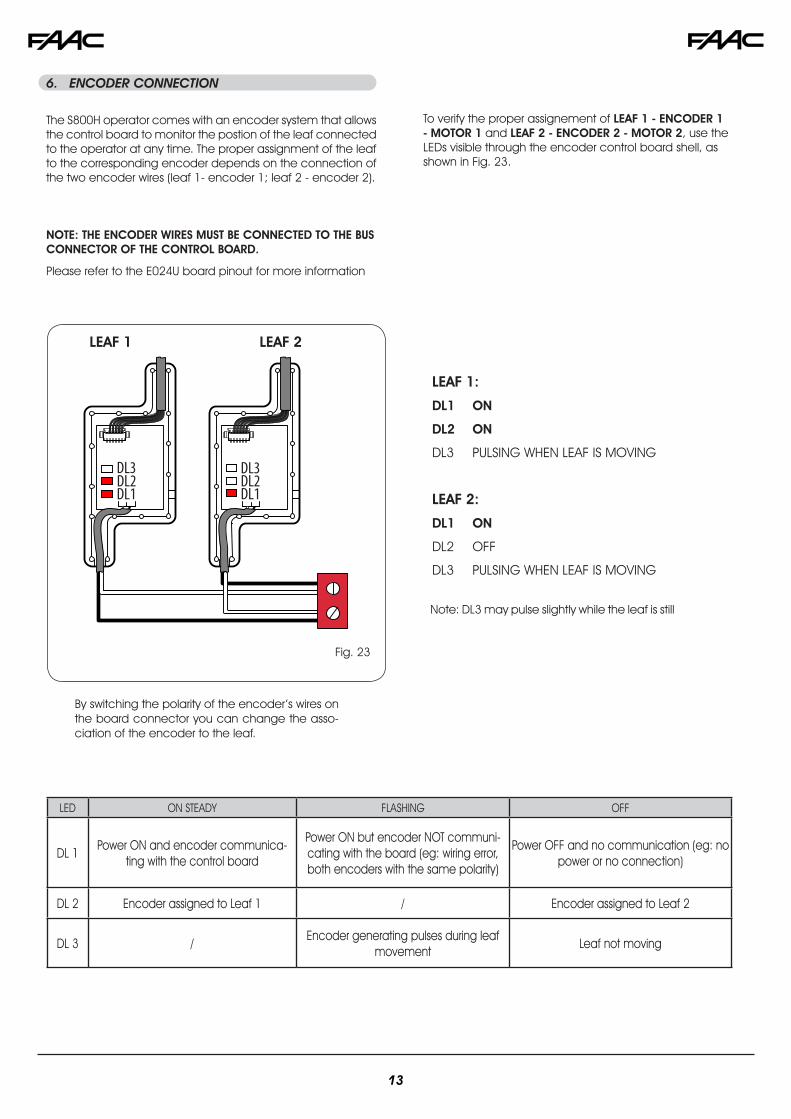
The S800H operator comes with an encoder system that allows the control board to monitor the postion of the leaf connected to the operator at any time. The proper assignment of the leaf to the corresponding encoder depends on the connection of the two encoder wires (leaf 1- encoder 1; leaf 2 - encoder 2).
By switching the polarity of the encoder’s wires on the board connector you can change the asso-ciation of the encoder to the leaf.
LED ON STEADY FLASHING OFF
DL 1Power ON and encoder communica-
ting with the control board
Power ON but encoder NOT communi-cating with the board (eg: wiring error, both encoders with the same polarity)
Power OFF and no communication (eg: no power or no connection)
DL 2 Encoder assigned to Leaf 1 / Encoder assigned to Leaf 2
DL 3 /Encoder generating pulses during leaf
movementLeaf not moving
To verify the proper assignement of LEAF 1 - ENCODER 1 - MOTOR 1 and LEAF 2 - ENCODER 2 - MOTOR 2, use the LEDs visible through the encoder control board shell, as shown in Fig. 23.
NOTE: THE ENCODER WIRES MUST BE CONNECTED TO THE BUS CONNECTOR OF THE CONTROL BOARD.
Please refer to the E024U board pinout for more information
6. ENCODER CONNECTION
DL1DL2DL3
DL1DL2DL3
LEAF 1:
DL1 ON
DL2 ON
DL3 PULSING WHEN LEAF IS MOVING
LEAF 2:
DL1 ON
DL2 OFF
DL3 PULSING WHEN LEAF IS MOVING
LEAF 1 LEAF 2
Fig. 23
Note: DL3 may pulse slightly while the leaf is still
13
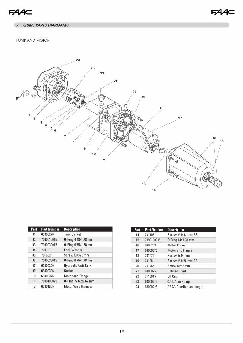
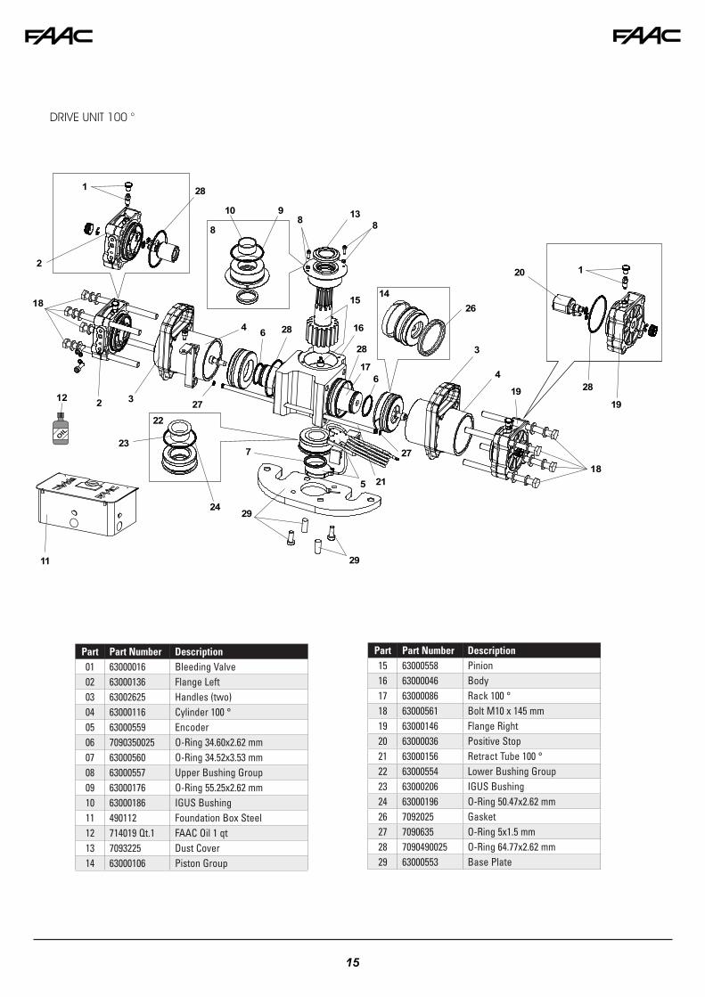
7. SPARE PARTS DIARGAMS
Part Part Number Description01 63000276 Tank Gasket02 7090010015 O-Ring 4.48x1.78 mm03 7090030015 O-Ring 6.75x1.78 mm04 703101 Lock Washer05 701632 Screw M4x25 mm06 7090030015 O-Ring 6.75x1.78 mm07 63000266 Hydraulic Unit Tank09 63000306 Gasket10 63000376 Motor and Flange11 7090100025 O-Ring 72.69x2.62 mm13 63001665 Motor Wire Harness
Part Part Number Description14 701103 Screw M4x12 mm SS15 7090190015 O-Ring 14x1.78 mm16 63002635 Motor Cover17 63000376 Motor and Flange18 701072 Screw 5x14 mm 19 70195 Screw M4x75 mm SS20 701245 Screw M6x8 mm21 63000256 Splined Joint22 7110015 Oil Cap23 63000246 0.5 Lt/min Pump24 63000226 CBAC Distribution flange
Main power supply 115 V~ 60 Hz Secondary power supply
24 Vdc - 16 A max.(min. 20 Vdc. - max. 36 Vdc.)
Power consumption stand-by = 4W max. = 400 WMax load per motor 7 AAccessory power 24 Vdc - 500 mABattery charge current 150 mAOperating temperature -4 °F +131 °F (-20 °C +55 °C)Protection fuses All self-resettingMain power fuse 6.3 A TimedOperating Logics E, A, S, EP, AP, SP, B, COperating time out 10 min.Pause time Programmable (0 to 4 min)
Motor force, speed, ob-stacle sensitivity, closing delay
Programmable with dedicated trimmer
Connector inputs Power supply, Battery, Radio receiver, USB
Terminal strip inputs Encoder, Open A, Open B, Stop, Open safety photocell, Closing safety photocell, Limit switches
Terminal strip outputs Audio Alarm, Lock, Motors, Accessory power supply
Programming With trimmers, dipswitchesand pushbutton
RADIO Connector for the radio receiverBATTERY Connector for the backup batteryJ24 Jumper to disable battery charging
(With the jumper present the battery charger is enabled)
POWER SUPPLY DC Power supply inputTR1 to TR6 Programming Trimmers+24 LED DC power indicatorSW1 - SETUP Pushbutton for automatic setupDS1 - DS2 Programming dipswitchesLED ERROR Troubleshooting indicatorUSB A USB connection for software upgrade
On the radio connector it’s possible to plug in receivers RP and RP2. With a single channel radio RP it will be possible to activate only the OPEN A input, with a dual channel radio RP2 it will be possible to activate both OPEN A and OPEN B inputs. Plug in the radio board with the component side towards the internal part of the board. Make sure you insert or disconnect the board ONLY with the power off.
1.1 TECHNICAL SPECIFICATIONS 1.2 LAYOUT AND COMPONENTS
1.3 RADIO CONNECTION
Fig. A1
1. E024U CONTROL BOARD DESCRIPTION & CHARACTERISTICS
This manual refers to board version 1D
16
A B STP CL OP OPEN FSW
24 VDCMaglock
Encoder
Fig. A2
MOT DL1 DL2
1 ON ON
2 ON OFF
PIN LABEL FUNCTION2 EASY 2 EASY 2easy BUS input for encoders (S800H and S450H only), XIB and loop detector boards
1 OPEN A N.O. Contact for total opening command
2 OPEN B /
CLOSE
OPEN B: N.O. Contact for opening of leaf 1 only (with only one leaf the opening stops at 50% of traveling) CLOSE (LOGIC B-C): N.O. Contact for closing command
3 STOP N.C. Contact for stop command
4 FSW CL N.C. Contact for closing safety
5 FSW OP N.C. Contact for opening safety
6 GND (-) 24 Vdc negative
7 GND (-) 24 Vdc negative
8 + 24 24 Vdc positive
9 OUT (-) 24 Vdc negative for safety TX photocell (monitored)
10 FCA 1 Open limit switch Motor 1
11 GND (-) 24 Vdc negative
12 FCC 1 Close limit switch Motor 1
13 FCA 2 Open limit switch Motor 2
14 GND (-) 24 Vdc negative
15 FCC2 Close limit switch Motor 2
LAMP LAMP Audio Alarm output
LOCK LOCKOutput for electrical lock, max 5A pulse (DS2 - SW 4=OFF) 12 Vac / 24Vdc
Always ON (maglock): max 1 A (DS2 - SW 4=ON) 24 Vdc
MOT1 MOT 1 Motor 1 output ( first moving motor )
MOT2 MOT 2 Motor 2 output ( second moving motor )
USB A USB Firmware upgrade input
2. INPUT / OUTPUT DESCRIPTION
17
CLOSE SAFETY
OPEN SAFETY
CL OP FSW
TX
TX
RX
RX
Connection of One Pair of Monitored Opening Photocells and One Pair of Monitored Closing
Photocells
CLOSE SAFETY
CL OP FSW
RX TX
Fig. A6RX= Receiver Photocell
TX= Transmitter Ptotocell
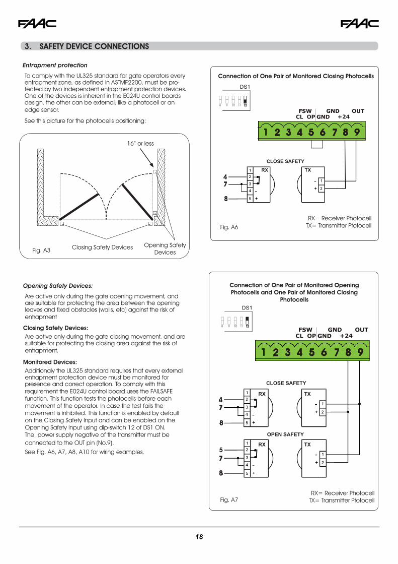
3. SAFETY DEVICE CONNECTIONS
Fig. A7
Entrapment protection
To comply with the UL325 standard for gate operators every entrapment zone, as defined in ASTMF2200, must be pro-tected by two independent entrapment protection devices. One of the devices is inherent in the E024U control boards design, the other can be external, like a photocell or an edge sensor.
Are active only during the gate opening movement, and are suitable for protecting the area between the opening leaves and fixed obstacles (walls, etc) against the risk of entrapment
Closing Safety Devices: Are active only during the gate closing movement, and are suitable for protecting the closing area against the risk of entrapment.
Monitored Devices: Additionaly the UL325 standard requires that every external entrapment protection device must be monitored for presence and correct operation. To comply with this requirement the E024U control board uses the FAILSAFE function. This function tests the photocells before each movement of the operator. In case the test fails the movement is inhibited. This function is enabled by default on the Closing Safety Input and can be enabled on the Opening Safety Input using dip-switch 12 of DS1 ON. The power supply negative of the transmitter must be connected to the OUT pin (No.9). See Fig. A6, A7, A8, A10 for wiring examples.
Connection of One Pair of Monitored Closing Photocells
RX= Receiver PhotocellTX= Transmitter Ptotocell
16” or less
DS1
DS1
18
Only one monitored photocell can be connected to the Closing or Opening safety inputs. More than one photocell or other device can be connected to the safety inputs, but they will not be monitored. Other devices connected to the safety inputs must have normally closed contacts and wired in series with the main monitored sensor. See the following example of one closing safety monitored photocell and one non monitored one.
Closing Safety Devices Opening Safety Devices
Opening/Closing Safety Devices
Opening/Closing Safety Devices: They operate during the gate opening and closing move-ments and are suitable to protect the opening and closing areas against the risk of impact. Typically these photocells work in combination with other monitored photocell pro-tecting closing or opening entrapment zones. In that case they can’t be monitored so they can only protect against potential impact on vehicles.
CLOSE SAFETY MONITORED
CL OP FSW
OPEN / CLOSE SAFETY NOT MONITORED
RX TX
RX TX
OPEN SAFETY MONITORED
RX TX
Connection of Two Pairs of Closing Photocells, One Monitored and One non Monitored
Fig. A8
Connection of One Pair of Closing Photocells (monitored), One Pair of Opening Photocells
(monitored) and One pair of Opening/Closing Photocells (non monitored)
Fig. A10
Fig. A9
CLOSE SAFETY NOT MONITORED
CL OP FSW
CLOSE SAFETY MONITORED
RX TX
RX TX
RX= Receiver PhotocellTX= Transmitter Ptotocell
RX= Receiver PhotocellTX= Transmitter Ptotocell
16” or less
DS1
DS1
19
OPERATING LOGIC
DS 1: SW 1 - SW 2 - SW 3 LOGIC SW 1 SW 2 SW 3
PAUSE TIME
DESCRIPTION
E (default)Semiautomatic
OFF OFF OFF NO One command opens, the next one closes. A command during opening stops the gate
A Automatic
ON ON ON0 - 4min
One command opens, waits for the pause time an then closes automatically
S Security
OFF OFF ON0-4 min
One command opens, waits for the pause time and then closes automatically. If the closing safety is activated or
another command is given during the pause time it closes. A maintained open command will not hold the gate open
EP Semiautomatic
step by step OFF ON OFF NO One command opens, the next one closes. During the mo-
vement a command stops the gate
AP Automatic step by step
OFF ON ON0-4 min
One command opens, waits for the pause time and then closes automatically. A command during the pause time
holds the gate open
SP Security
step by stepON OFF OFF
0-4 min
One command opens, waits for the pause time and then closes automatically. If the closing safety is activated during pause time the gate closes in 5 s. A command during pau-
se time holds open the gate
B Manned Pulsed
ON OFF ON NO An open A command opens the gate, an open B com-mand closes the gate
C Manned Constant
ON ON OFF NO Holding open A active opens the gate, holding Open B acti-ve closes the gate
For more details on the operating logics please refer to Chapter 11 - Function Logics
4.1 DIP SWITCH DS1 SETTINGS FOR OPERATING LOGIC
4. PROGRAMMING
20
6
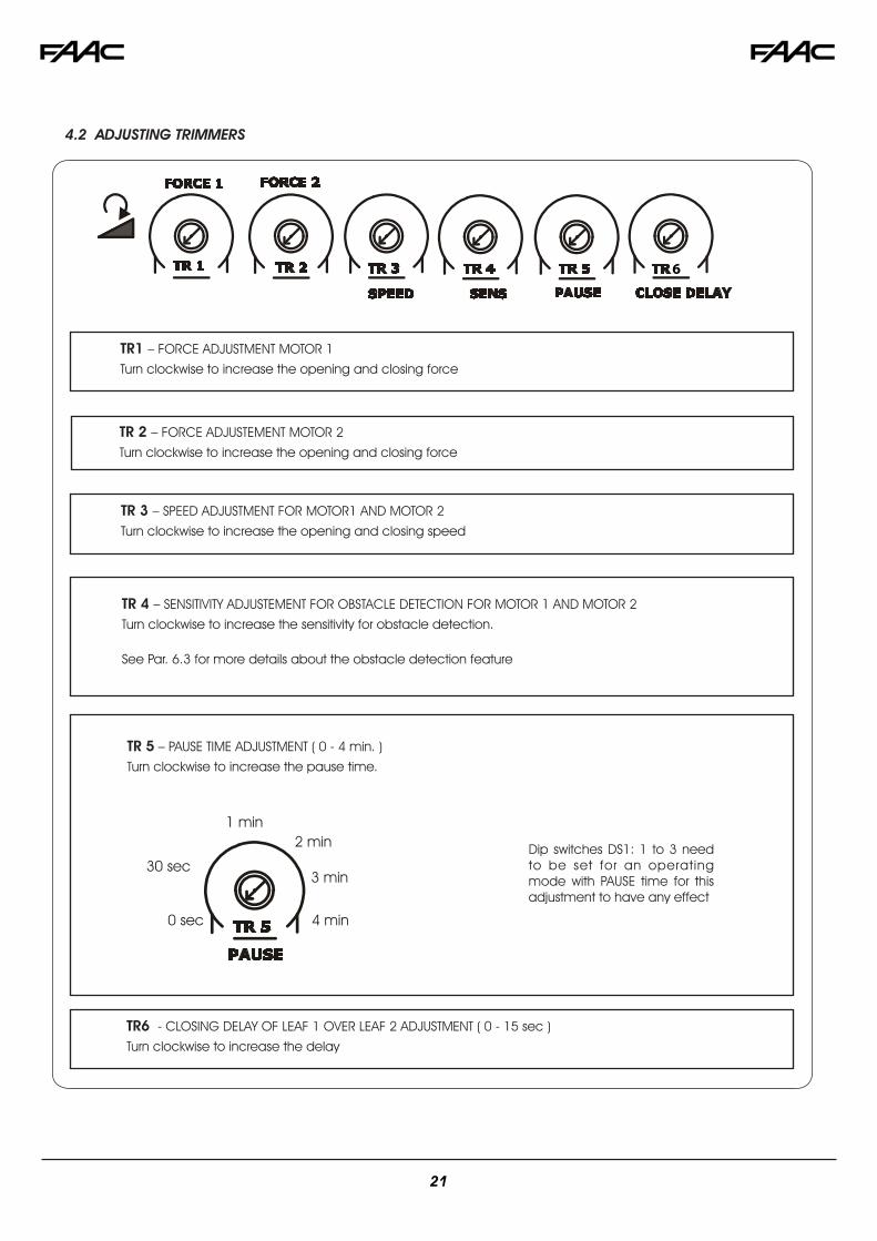
TR 3 – SPEED ADJUSTMENT FOR MOTOR1 AND MOTOR 2
Turn clockwise to increase the opening and closing speed
TR 4 – SENSITIVITY ADJUSTEMENT FOR OBSTACLE DETECTION FOR MOTOR 1 AND MOTOR 2
Turn clockwise to increase the sensitivity for obstacle detection.
See Par. 6.3 for more details about the obstacle detection feature
TR 5 – PAUSE TIME ADJUSTMENT ( 0 - 4 min. )
Turn clockwise to increase the pause time.
TR6 - CLOSING DELAY OF LEAF 1 OVER LEAF 2 ADJUSTMENT ( 0 - 15 sec )
Turn clockwise to increase the delay
TR1 – FORCE ADJUSTMENT MOTOR 1
Turn clockwise to increase the opening and closing force
1 min2 min
3 min
4 min0 sec
30 sec
TR 2 – FORCE ADJUSTEMENT MOTOR 2
Turn clockwise to increase the opening and closing force
4.2 ADJUSTING TRIMMERS
Dip switches DS1: 1 to 3 need to be set for an operating mode with PAUSE time for this adjustment to have any effect
21
BOARD SETUP DS 1: SW 4 to SW 12
OPENING DELAY SW 4 The opening of leaf 2 is delayed after the opening of leaf 1. This is to avoid the gate leafs interfering with each other during the initial part of the move-ment. In case there is only one leaf it has no effect.0 sec (default) OFF
2 sec ONREVERSE AND LAST STROKE SW 5 If active, before opening, while the gate is closed, the motors thrust to clo-
se for 2 s to facilitate the release of the electric lock. At closing the motors are activated for a final stroke after slowdown to facilitate locking of the electric lock.
inactive (default) OFFactive ON
MAX THRUST AT STARTUP SW 6 With this fuction active the motors work at maximum force at startup (re-gardless of the force setting) during the initial phase of the movement. Useful for heavy leavesinactive (default) OFF
active for 3 sec ONAUTOMATIC OPENING IN CASE OF
POWER FAILURESW 7 If active and with the optional backup battery installed, the board will open
the gate after one minute from the power failure and keep it open.Within the minute wait it’s always possible to open and close the gate with a command. If the logic used has a pause time the board will close the gate when the power comes back.
inactive (default) OFFactive ON
CLOSING SAFETY LOGIC SW 8 With this function you can choose the behavior of the closing safety. With SW8 OFF the gate movement will be reversed as soon as the safety is active, with SW8 ON the gate will stop when the safety is active and it will reverse only when the safety is deactivated.
immediate reverse (default) OFFreverse when cleared ON
SHADOW LOOP CONFIGURATION SW 9 Selects the behavior of the shadow loop function of the XIB accessoryOFF: The shadow loop input is active only before a closing command, ignored in any other conditionsON: The shadow loop input is active before a closing and before an opening command. If an open command is given and the shadow loop input is engaged the open command will be ignored even after the shadow loop input goes inactive.NOTE: On the first power up of the board an open command will be always executed (even if the shadow loop is engaged), but at reduced speed.
active only on closing (default) OFFactive on closing and opening ON
EXTRA SENSITIVITY TO OBSTACLE DETECTION
SW 10 If active this function allows to have an immediate reverse in case the gate hits a rigid obstacle. This function increases the safety of the gate operator, however it can generate unwanted obstacle detections.
inactive (default) OFFactive ON
24V ACCESSORY VOLTAGE SW 11 Selects the behavior of the 24V accessory voltage during battery mode:OFF: The accessory voltage and BUS input are turned off in battery backup modeON: The accessory voltage and BUS input are always active even in bat-tery backup mode
24V OFF in Battery Mode OFF
24V ON in Battery Mode ON
FAIL SAFE MODE SW 12 Selects the behavior of the Fail Safe (monitoring) mode:
OFF: Fail Safe is active on the closing safety photocell input (FSW CL) only
ON: Fail Safe is active on both closing safety photocell input (FSW CL) and opening safety photocell input (FSW OP)NOTE: if using the XIB interface the opening safety on it is also monitored. Refers to the XIB manual for further details.
Closing Safety OFF
Closing and Opening Safety ON
4.3 DIP SWITCH DS1 SETTINGS FOR BOARD SETUP
22
DS2
SETTING
+J24
1
2
3 45
678 9 10
DL19 DL20 DL21 DL22 DL14 DL15 DL16 DL17 DL18
Reserved
DS 2 OPERATOR SELECTION
OPERATOR TYPE SW 1 SW 2 SW 3S450H, S800H OFF OFF OFF
S418 OFF OFF ON415, 390, 770 ON OFF OFF
DS 2LOCK OUTPUT MODEOUTPUT MODE SW 4
Active only for 3 sec. after an open impulse (from gate closed)
OFF
Active always except 3 sec. before an opening ON
SETTING
+
DL 1 DL 2 DL 3 DL 4 DL 5
J24
IMPORTANT
4.4 DIP SWITCH DS2 SETTINGS FOR OPERATOR TYPE AND LOCK MODE
5. LED DIAGNOSTICS
23
L
E
D
DESCRIPTION
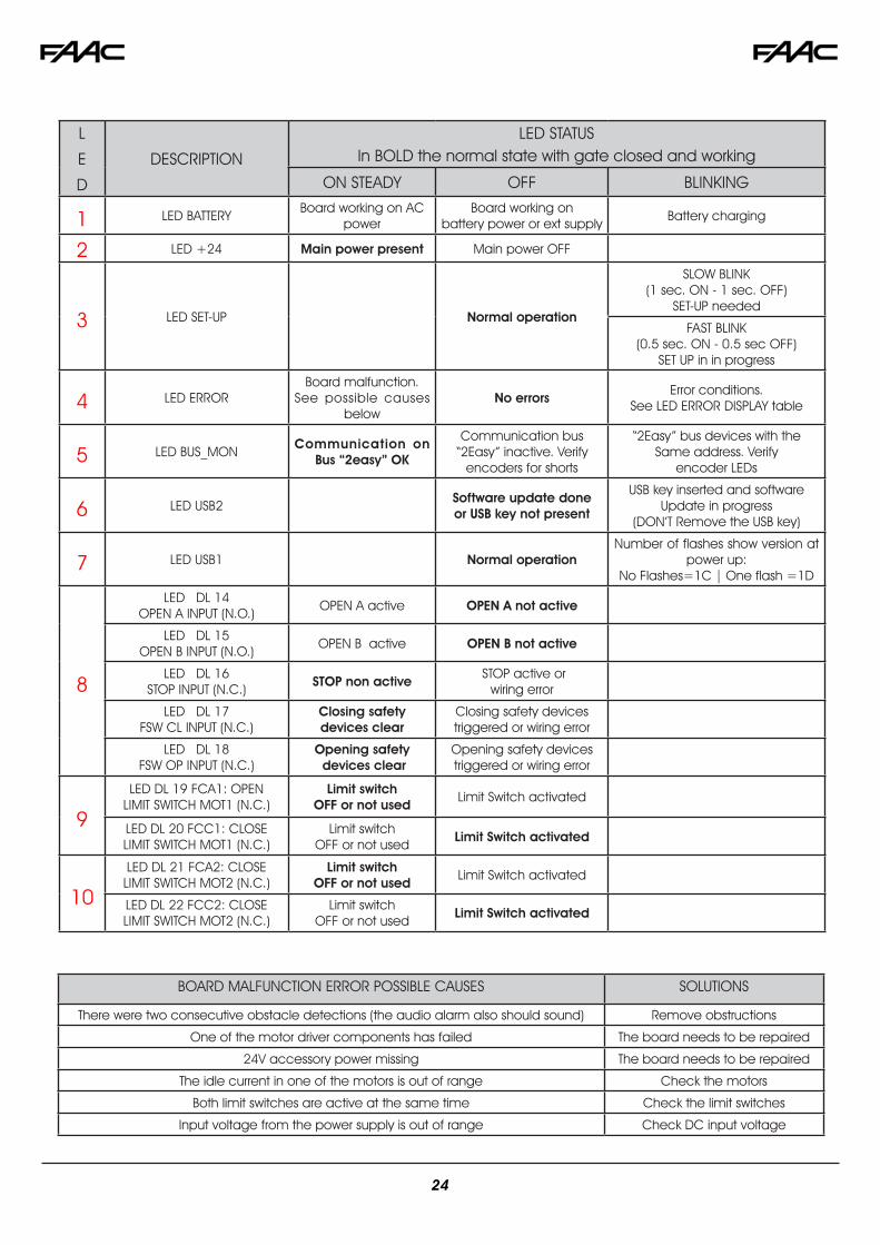
LED STATUS In BOLD the normal state with gate closed and working
ON STEADY OFF BLINKING
1 LED BATTERYBoard working on AC
powerBoard working on
battery power or ext supplyBattery charging
2 LED +24 Main power present Main power OFF
3 LED SET-UP Normal operation
SLOW BLINK (1 sec. ON - 1 sec. OFF)
SET-UP needed
FAST BLINK(0.5 sec. ON - 0.5 sec OFF)
SET UP in in progress
4 LED ERRORBoard malfunction.
See possible causes below
No errorsError conditions.
See LED ERROR DISPLAY table
5 LED BUS_MONCommunication on
Bus “2easy” OK
Communication bus “2Easy” inactive. Verify
encoders for shorts
“2Easy” bus devices with the Same address. Verify
encoder LEDs
6 LED USB2Software update doneor USB key not present
USB key inserted and softwareUpdate in progress
(DON’T Remove the USB key)
7 LED USB1 Normal operation Number of flashes show version at
power up: No Flashes=1C | One flash =1D
8
LED DL 14 OPEN A INPUT (N.O.)
OPEN A active OPEN A not active
LED DL 15OPEN B INPUT (N.O.)
OPEN B active OPEN B not active
LED DL 16 STOP INPUT (N.C.)
STOP non active STOP active or
wiring error
LED DL 17 FSW CL INPUT (N.C.)
Closing safety devices clear
Closing safety devicestriggered or wiring error
LED DL 18 FSW OP INPUT (N.C.)
Opening safety devices clear
Opening safety devicestriggered or wiring error
9
LED DL 19 FCA1: OPENLIMIT SWITCH MOT1 (N.C.)
Limit switchOFF or not used
Limit Switch activated
LED DL 20 FCC1: CLOSELIMIT SWITCH MOT1 (N.C.)
Limit switchOFF or not used
Limit Switch activated
10
LED DL 21 FCA2: CLOSELIMIT SWITCH MOT2 (N.C.)
Limit switchOFF or not used
Limit Switch activated
LED DL 22 FCC2: CLOSELIMIT SWITCH MOT2 (N.C.)
Limit switchOFF or not used
Limit Switch activated
BOARD MALFUNCTION ERROR POSSIBLE CAUSES SOLUTIONS
There were two consecutive obstacle detections (the audio alarm also should sound) Remove obstructions
One of the motor driver components has failed The board needs to be repaired
24V accessory power missing The board needs to be repaired
The idle current in one of the motors is out of range Check the motors
Both limit switches are active at the same time Check the limit switches
Input voltage from the power supply is out of range Check DC input voltage
24
WARNING: If the time learning setup is done automatically then the slow down points are set by the board on his own
Move the leafs to the mid positionVery important for a good result
1. Press and hold the SETUP button until the SETUP LED lights up, wait about 3 sec. until it turns off and then release it imme-diately. NOTE: If you wait too long to release it the manual set-up will start. The LED will blink during the setup procedure
2. Leaf 2 (if present) starts to move slowly in closing direction, stopping when it reaches the mechanical stop or FCC2.
3. Leaf 1 begins to move slowly in closing direction, stopping when it reaches the mechanical stop, or FCC1.
4. Leaf 1 starts to move slowly in opening direction, followed by leaf 2 (if present) still slowly.
5. When they both reach the open mechanical stop or FCA1 and FCA2 they stop and reverse, leaf 2 (if present) automa-tically starts closing at full speed followed by leaf 1.
6. When they reach the close mechanical stop or FCC1 and
After powering up the board for the first time or when the board will need it the setup LED will blink at a slow frequency to indicate that the setup procedure to learn the running times is needed.
The setup can be redone at any time by pressing and holding the setup button as indicated below. The setup cannot be done until the safeties and stop inputs are wired.
After the setup first movement, if the leafs are opening instead of closing you need to reverse the wires going to the motor that moves in the wrong direction
LED ERROR DISPLAYNUMBER OF
FLASHESERROR CONDITION SOLUTION
1 OBSTACLE DETECTION Remove the obstacle, Check force and sensitivity settings
2BOARD IN SLEEP MODE(Slow blinking means that the automatic open in case of power failure function is active)
Verify the presence of AC power
3 MOTOR 1 FAILURE Inspect wiring to motor. If the wiring is good replace motor 1
4 MOTOR 2 FAILURE Inspect wiring to motor. If the wiring is good replace motor 2
5
ENCODER on motor 1 or motor 2 error • Verify the encoder wiring and LED status. If they are correct replace the encoder
• Verify motor and encoder wire gauge are correct• Verify operator is not on manual and hydraulic units don’t need
to be bled
6 FAIL SAFE FAILED Verify the photocells wiring and alignement
7 BOARD THERMAL PROTECTION ACTIVE Turn off the board and wait until the components cool down
8
MAX RUN TIME REACHED WITHOUT FINDING THE POSITIVE STOP (10 min. )
- Verify that the operator manual release is not engaged- Verify that the board recognizes the mechanical stop, in case redo the setup procedure- Verify that the gates slow down before reaching the positive stops. If they don’t then redo the setup procedure
The diagnostic LED shows only one error condition at a time, with the priority of the below table. In case there is more than one error once one is eliminated the LED will show the next
FCC2 both leafs stop and leaf 1 restarts automatically opening at full speed followed by leaf 2 (if present).
7. If you selected an automatic logic the board will wait for the pause time and then closes the gate automatically. Otherwise you have to give an OPEN command to close the gate.
WARNING: If the manual time learning setup is done then the slow down points must be set by the installer during the proce-dure. Slow down is required for proper operation.
Move the leafs to the mid positionVery important for a good result
1. Press and hold the SETUP button until the SETUP LED lights up, keep it pressed for about 3 sec. until it turns off and keep it pressed more until the leaf 2 (if present) starts moving slowly. The LED will blink during the setup procedure
2. Leaf 2 will move in closing direction until it reaches the mechanical stop or FCC2
3. Leaf 1 starts moving slowly until it reaches the mechanical stop or FCC1
4. Leaf 1 starts moving in opening direction at the set speed (trimmer speed).
5. At the point where you want the slowdown to start give an OPEN A command with the push button or the remote that is already stored in memory. Leaf 1 starts to slow down and stops when it reaches the mechanical stop or FCA1.
6. Leaf 2 starts moving in opening direction at the set speed (trimmer speed)
6.1 AUTOMATIC TIME LEARNING
6.2 MANUAL TIME LEARNING
6. TIME LEARNING (SET-UP)
25
The obstacle detection function is achieved by controlling the current absorption and / or through the encoder connected to the motors.
If the gate encounters an obstacle during the movement of opening or closing, the obstacle detection function is activa-ted and the operator reverses the direction of the gate.
In case of a second consecutive obstacle the operator stops the gate right away and any further command is inhibited. To re-enable the automation, you must remove power (and disconnect batteries if present) or open the STOP contact input. The Audio Alarm output will be active until this “reset”.
7. At the point where you want the slowdown to start give an OPEN A command with the push button or the remote that is already stored in memory. Leaf 2 starts to slow down and stops when it reaches the mechanical stop or FCA2.
8. Leaf 2 starts to close at the set speed (trimmer speed).9. At the point where you want the slowdown to start give an
OPEN A command with the push button or the remote that is already stored in memory. The leaf 2 starts to slow down and stops when it reaches the mechanical stop or FCC2.
10. Leaf 1 starts to close at the set speed (trimmer speed). 11. At the point where you want the slowdown to start give an
OPEN A command with the push button or the remote that is already stored in memory. Leaf 1 starts to slow down and stops when it reaches the mechanical stop or FCC1.
12. The manual time learning procedure is complete.
After time learning test the gate to set the force, speed and sensitivity using the trimmers.
15 15/32”
6 7/32”
17 1
5/32
”The E024U board is supplied on a panel that fits in a 16x14” enclosure.
6.3 OBSTACLE DETECTION FUNCTION
7. ENCLOSURE
1. Apply resistance to the gate and adjust the Force to make sure that the operator creates enough thrust to reliably move the leaf.
2. Set the desired speed. Keep the speed relatively low on big and heavier gates.
3. After Force and Speed are set to the desired settings adjust the Sensitivity so the gate reverses promptly after hitting a rigid object.
4. After all the adjustments are done perform setup again.
This is a more detailed description of what happens after an obstacle detection:
Gate opening, obstacle detected:
The gate reverses partially (for 3 sec.) and STOPS. After that the gate is in a halfway position or completely closed.
If an open_A command is received, the gate tries to open from the current position:
• If there is another obstacle detection: the gate stops com-pletely, the alarm goes off
• If the gate reaches the open position: the obstructions count is reset, the gate returns to normal operations
Gate closing, obstacle detected:
The gate reverses partially (for 3 sec.) and STOPS. After that the gate is in a halfway position or completely open.
If an open_A command is received in NON Automatic mode
• if the gate was not completely open: execute an open
• if the gate was completely open: execute a close
If an open_A command is received in Automatic mode:
• if the gate was not completely open: execute an open, wait for the pause time and then closes.
• if the gate was completely open: reload the pausetime, and then closes
If there is another obstacle detection: the gate stops comple-tely, the alarm goes off.
If the gate reaches the close position: the obstructions count is reset, the gate returns to normal operations
26
On the back panel there are: the control board, the power supply and additional accessories.
Power Supply
AC connectionPower outletand switch(optional)
Pushbutton(optional)
E24U board
DIN rail
Batteries
AC POWER CONNECTIONTo connect AC power to the controller:
1. Turn the circuit breaker for the AC gate operator power OFF before connecting the AC input wires.
2. Turn OFF the Power Switch located on the left side of enclosure before connecting the AC input wires.
3. Connect the AC input wires to the AC terminal located on the top left of the control box. See diagram below.
4. Batteries must be installed after the AC power is on. See Battery Power Connection.
AC POWER GUIDELINES:THE E024U control board and power supply uses a single phase AC power line to operate, charge the batteries, and power gate accessories. Use the following guidelines when installing the AC power:
1. Check the local wiring codes in all cases and follow all local building codes. Wiring and hookup should be performed by a qualified electrician/installer only.
2. AC power should be supplied from a circuit breaker panel and must have its own dedicated circuit breaker. This supply must include a green ground conductor.
3. Use copper conductor wires with liquid tight flexible conduit UL listed for electric cable protection
14 AWG, 600V, 80°C Terminal Block max Torque 2.1 Nm
4. Properly ground the gate operator to minimize or prevent damage from power surges and/or lightning. Use a grounding rod if necessary. A surge suppressor is recommended for ad-ditional protection.
8. POWER CONNECTION
BLACK
WHITE
GREEN
115 V LINE
NEUTRAL
GROUND
The E024U board is powered by a high efficiency switching power supply that takes 115VAC input and provides 36VDC to power the board. On the power supply board there is only one repleaceble fuse: 6.3A timed
8.1 POWER SUPPLY
FUSE
27
SETTING
+
DL 1 DL 2 DL 3 DL 4 DL 5
J24
The internal battery charger must be disabled to use an external charger. To disable the battery charger unplug jumper J24
J24 PRESENT = BATTERY CHARGING ACTIVEJ24 NOT PRESENT = BATTERY CHARGING NOT ACTIVE
9.1 DISABLE THE BATTERY CHARGER
SETTING
+
DL 1 DL 2 DL 3 DL 4 DL 5
J24
1. Disconnect the batteries if they are present.2. Turn the AC power off and insert the Flash Drive into the
USB A input on the board3. Turn the AC power back on. The USB2 LED will start to flash to
confirm the beginning of the software update. (WARNING: DON’T TURN THE POWER OFF OR REMOVE THE FLASH DRIVE UNTIL THE USB2 LED TURNS OFF.
4. Wait until the USB 2 LED turns off5. Remove the USB Flash drive.6. Cycle power, reconnect the batteries if needed and exe-
cute a new SETUP procedure (See chapter 6)
For the upgrade you need a USB Flash Drive, where you have to copy the file supplied by FAAC. Then follow these steps:
WARNING: Only upgrade the firmware with the proper file supplied by FAAC, otherwise the board could be damaged
The E024U board keeps the operating firmware in a field pro-grammable memory, it can be easily upgraded through the on board USB port
10. FIRMWARE UPGRADE
The E024U board allows the connection of a 24V backup battery to provide power to operate the gate during blackouts. For more details about how the boards handles the loss of main power and how to configure its behaviour please see par 4.3 and DS1 switch 7.
To connect the battery use the provided cable and jumper. Plug the jumper from the red (+) terminal of first battery to the black (-) terminal on the second battery and then connect the battery cable red wire to the red (+) terminal on the second battery and the black wire to the black (-) terminal on the first battery. Finally plug the cable on the BATTERY connector on the board.
SETTING
+
DL 1 DL 2 DL 3 DL 4 DL 5
J24
9. BACKUP BATTERY
12VDC, 8 amp Battery
12VDC, 8 amp Battery
+
+
-
-
RED
BLACK
JUMPER
On initial power up watch the LED USB 1 on the bottom left of the board. The number of flashes indicate the version:No Flashes = Version 1C, refer to manuals dated Jan. 2016 and before. 1 FLash = Version 1D refer to manuals dated after Jan. 2016
10.1 VERIFY THE FIRMWARE VERSION
28
LOGIC “S” PULSES
SYSTEM STATUS OPEN A OPEN B STOP FSW OP FSW CL FSW CL/OP
CLOSED opens and closes after pause time
opens released leaf and closes after pause time
no effect (OPEN disabled)
no effect (OPEN disabled) no effect no effect
(OPEN disabled)
OPENING no effect (1) no effect stops operation reverses at closure continues to open and recloses immediately
stops and opens at release (saves CLOSE)
OPEN IN PAUSE recloses leaves immediately (1)
recloses leaves immediately stops operation no effect stops and, at release,
closesstops and, at release,
closes
CLOSING reopens leaves immediately
reopens leaves immediately stops operation no effect
reverses at opening (see DS1-SW8) and closes immediately at end
stops and opens after release and closes immediately at
end
BLOCKED closes leaves closes leavesno effect
(OPEN/CLOSE disabled)
no effect (OPEN disabled)
no effect (CLOSE disabled)
no effect (OPEN/CLOSE disabled)
(1) if the cycle began with OPEN-B (leaf 1), both leaves are activated at opening
LOGIC “E” PULSES
SYSTEM STATUS OPEN A OPEN B STOP FSW OP FSW CL FSW CL/OP
CLOSED opens the leaves opens leaf 1 no effect (OPEN disabled)
stops and opens after release and closes immediately at end (OPEN
stops - saves CLOSE)
OPEN IN PAUSE recloses leaves immediately (1)
recloses leaves immediately stops operation no effect stops and, at relea-
se, closes stops and, at release, closes
CLOSING stops operation stops operation stops operation no effect reverses at opening stops and opens at release (saves CLOSE)
BLOCKED
restarts moving in opposite
direction. Always closes after STOP
restarts moving in opposite direction. Always closes after
STOP
no effect (OPEN/CLOSE
disabled)
no effect (OPEN disabled)
no effect (CLOSE disabled)
no effect (OPEN/CLOSE disabled)
(1) if the cycle began with OPEN-B (leaf 1), both leaves are activated at opening
30
LOGIC “B” PULSES
SYSTEM STATUS OPEN A OPEN B STOP FSW OP FSW CL FSW CL/OP
CLOSED opens the leaves no effect no effect (OPEN disabled)
no effect (OPEN disabled) no effect no effect
(OPEN disabled)
OPENING no effect closes leaves stops operation reverses at closure no effectstops and, at release, closes
(saves OPEN/CLOSE)
OPEN no effect closes leavesno effect
(OPEN/CLOSE disabled)
no effect no effect (CLOSE disabled)
no effect (OPEN/CLOSE disabled)
CLOSING opens the leaves no effect stops operation no effect reverses at opening stops and opens at release
(saves OPEN/CLOSE)
BLOCKED opens the leaves closes leavesno effect
(OPEN/CLOSE disabled)
no effect (OPEN disabled)
no effect (CLOSE disabled)
no effect (OPEN/CLOSE disabled)
LOGIC “C” CONTINUOS COMMANDS PULSES
SYSTEM STATUS OPEN A OPEN B STOP FSW OP FSW CL FSW CL/OP
CLOSED opens the leaves no effect no effect (OPEN disabled)
no effect (OPEN disabled) no effect no effect
(OPEN disabled)
OPENING no effect closes leaves stops operation reverses at closure no effectstops and, at release, closes
(saves OPEN/CLOSE)
OPEN no effect closes leavesno effect
(OPEN/CLOSE disabled)
no effect no effect (CLOSE disabled)
no effect (OPEN/CLOSE disabled)
CLOSING opens the leaves no effect stops operation no effect reverses at opening stops and opens at release
(saves OPEN/CLOSE)
BLOCKED opens the leaves closes leavesno effect
(OPEN/CLOSE disabled)
no effect (OPEN disabled)
no effect (CLOSE disabled)
no effect (OPEN/CLOSE disabled)
31
12. ACCESSORIES
12.1 SHADOW LOOP INTERFACE (p/n 790062)
Through the use of the XIB interface board you can connect an additional loop detector (center or shadow) to the E024U board to keep the gate open if vehicles are obstructing the closing path. With a dip switch setting the shadow loop can function on both opening and closing (see section 4.3)
J2
J3
DL1
DL2
J1
CL
OP
XIB board description
CL
OP
BUS
BUS
BUS
N.C.
N.O.
COM
XIB board connections with no opening safety
Encoder
Interface
Detector
J1 ( RED ) Connects to “2easy” BUS input on the E024U
J2 ( RED ) Terminal for the connection of the encoder
J3 CL (GREEN) Terminal for the NC connection of the shadow loop detector
J3 OP (GREEN ) Terminal for the NC connection of second open safety
DL1 LED for diagnostics of devices connected to the J3 OP
DL2 LED for diagnostics of devices connected to the J3 CL
INSTALLING THE INTERFACE
1. Turn power OFF
2. Plug in the XIB interface to the 2EASY connector on the E024U board
3. Wire the shadow loop detector NC output to the CL input on the XIB board as in figure below
4. Connect Common from loop detector to GND (terminal 6) on E024U
5. If no second open safety device is present jump out the OP input on XIB board to GND (terminal 6) on the E024U
6. Wire the encoder (if needed) to J2
7. Refer to Fig. A11 for the wiring schematic
8. Turn power back ON
9. Press and release the SW1 button quickly. The board will recognize that the XIB board has been removed
10. Re-program run time if needed.
REMOVING THE INTERFACE
1. Turn power OFF
2. Unplug the board and remove the wiring
3. Move the encoder wires (if present) to the 2EASY con-nector on the board
4. Turn power back ON
5. Verify that leaf 1 & 2 lights on the encoder are correct
6. Press and release the SW1 button quickly. The board will recognize that the XIB board has been removed
7. Re-program run time if needed.
NOTE:
• Do not connect the shadow loop detector in series with regular closing safety devices.
• If the E024U board doesn’t have the correct software installed the shadow loop will act as a normal closing safety, detecting also the gate itself and not allowing the closing movement to complete. Please contact techni-cal support for assistance in that case.
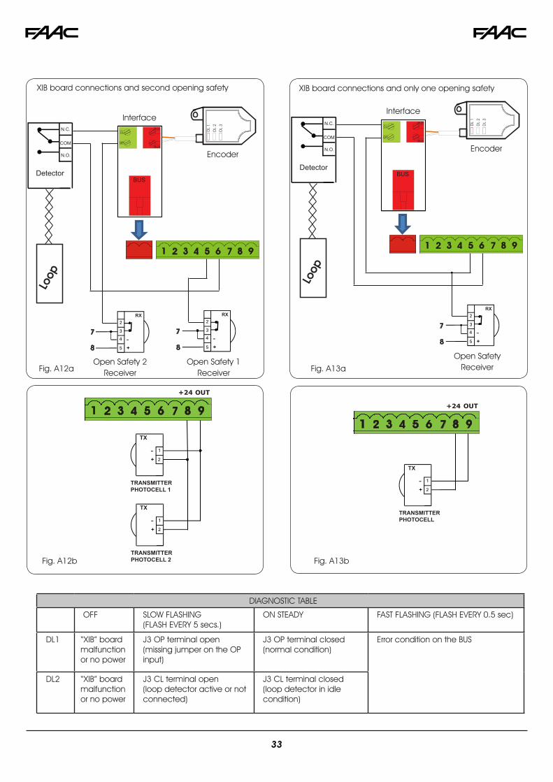
SECOND OPEN SAFETY INPUT
The OP input on the XIB board can be used as a second monitored open safety input.
When open safety monitoring is turned ON on the E024U board (Dip SW 12 ON) the OP input on the XIB (J3 OP) is moni-tored and can be used to protect an entrapment zone. See Fig. A12a/b for the connections.
In case only one opening safey input is needed and the XIB board is present connect the opening safey photocell to FSW OP on the E024U and J3 OP on the XIB in parallel. See Fig. A13a/b for the connections.
Fig. A11
32
RX
TRANSMITTER PHOTOCELL
TX
TRANSMITTER PHOTOCELL 1
TX
TRANSMITTER PHOTOCELL 2
TX
DIAGNOSTIC TABLE
OFF SLOW FLASHING (FLASH EVERY 5 secs.)
ON STEADY FAST FLASHING (FLASH EVERY 0.5 sec)
DL1 “XIB” board malfunction or no power
J3 OP terminal open (missing jumper on the OP input)
J3 OP terminal closed(normal condition)
Error condition on the BUS
DL2 “XIB” board malfunction or no power
J3 CL terminal open (loop detector active or not connected)
J3 CL terminal closed(loop detector in idle condition)
CL
OP
BUS
BUS
BUS
N.C.
N.O.
COM
Detector
RX
XIB board connections and second opening safety
Interface
Encoder
Open Safety 2 Receiver
Open Safety 1 Receiver
CL
OP
BUS
BUS
BUS
N.C.
N.O.
COM
Detector
RX
XIB board connections and only one opening safety
Interface
Encoder
Open Safety ReceiverFig. A12a Fig. A13a
Fig. A12b Fig. A13b
33
The Loop Detector Interface allows connection of up to three plug-in detectors associated with standard functions. The board is designed to fit in the FAAC standard 16” x 14” enclo-sure on the existing DIN rail. To connect the interface board:
1) Connect the 2EASY BUS from the E024U to the interface board (no polarity) - Green Wires
2) Connect pin 8 on the E024U board (+24V) to the +24 input on the interface board - Red Wire
3) Connect pin 7 on the E024U board (GND) to the GND input on the interface board - Black Wire
4) Connect the loops to the interface board as in the figure below
A B STP CL OP OPEN FSW
OPENREVERSESHADOW
E024U CONTROL BOARD
SHAD
OW
REVER
SE
OPEN
LED
Turn the power on on the E024U board. The LED on the inter-face board will blink briefly and then will stay ON solid if the BUS connection is working correctly.
IMPORTANT: Briefly press the SW1 button on the E024U board to make it aware of the presence of the additional interface board.
To make sure the board is working properly you can check the behaviour of BUS LED on the E024U board. It will be nor-mally on when none of the loop detectors is active. If any of the detectors is activated the LED will turn off.
12.2 LOOP DETECTORS INTERFACE (p/n 2670)
NOTE: You can use the shadow loop interface OR the loop detectors interface but not both at the same time. If two monitored open safeties are required the additional loop detectors (other than the shadow) must be wired directly to the E024U board.
Loop Detectors Interface Wiring
34
To the original purchaser only:
FAAC International, Inc., warrants, for twenty-four (24) months from the date of invoice, the gate operator systems and other related systems and equipment manufactured by FAAC S.p.A. and distributed by FAAC International, Inc., to be free from defects in material and workmanship under normal use and service for which it was intended provided it has been properly installed and operated.
FAAC International, Inc.’s obligations under this warranty shall be limited to the repair or exchange of any part of parts manufactured by FAAC S.p.A. and distributed by FAAC International, Inc. Defective products must be returned to FAAC International, Inc., freight prepaid by purchaser, within the warranty period. Items returned will be repaired or replaced, at FAAC International, Inc.’s option, upon an examination of the product by FAAC International, Inc., which discloses, to the satisfaction of FAAC International, Inc., that the item is defective. FAAC International, Inc. will return the warranted item freight prepaid. The products manufactured by FAAC S.p.A. and distributed by FAAC International, Inc., are not warranted to meet the specific requirements, if any, of safety codes of any particular state, municipality, or other jurisdiction, and neither FAAC S.p.A. or FAAC International, Inc., assume any risk or liability whatsoever resulting from the use thereof, whether used singly or in combination with other machines or apparatus.
Any products and parts not manufactured by FAAC S.p.A. and distributed by FAAC International, Inc., will carry only the warranty, if any, of the manufacturer. This warranty shall not apply to any products or parts thereof which have been repaired or altered, without FAAC International, Inc.’s written consent, outside of FAAC International, Inc.’s workshop, or altered in any way so as, in the judgment of FAAC International, Inc., to affect adversely the stability or reliability of the product(s) or has been subject to misuse, negligence, or accident, or has not been operated in accordance with FAAC International, Inc.’s or FAAC S.p.A.’s instructions or has been operated under conditions more severe than, or otherwise exceeding, those set forth in the specifications for such product(s). Neither FAAC S.p.A. nor FAAC International, Inc., shall be liable for any loss or damage whatsoever resulting, directly or indirectly, from the use or loss of use of the product(s). Without
limiting the foregoing, this exclusion from liability embraces a purchaser’s expenses for downtime or for making up downtime, damages for which the purchaser may be liable to other persons, damages to property, and injury to or death of any persons.
FAAC S.p.A. or FAAC International, Inc., neither assumes nor authorizes any person to assume for them any other liability in connection with the sale or use of the products of FAAC S.p.A. or FAAC International, Inc. The warranty herein above set forth shall not be deemed to cover maintenance parts, including, but not limited to, hydraulic oil, filters, or the like. No agreement to replace or repair shall constitute an admission by FAAC S.p.A. or FAAC International, Inc., of any legal responsibility to effect such replacement, to make such repair, or otherwise. This limited warranty extends only to wholesale customers who buy directly through FAAC International, Inc.’s normal distribution channels. FAAC International, Inc., does not warrant its products to end consumers.
Consumers must inquire from their selling dealer as to the nature and extent of that dealer’s warranty, if any. This warranty is expressly in lieu of all other warranties expressed or implied including the warranties of merchantability and fitness for use. This warranty shall not apply to products or any part thereof which have been subject to accident, negligence, alteration, abuse, or misuse or if damage was due to improper installation or use of improper power source, or if damage was caused by fire, flood, lightning, electrical power surge, explosion, wind storm, hail, aircraft or vehicles, vandalism, riot or civil commotion, or acts of God.