Ex e B.39 ED.2017 B.39 SA-P ED.2017 ORIGINAL PRODUCT - Zone 1, 2, 21, 22 - Polyester junction boxes - Choice of 9 sizes - With antistatic property - IK10 mechanical strength - IP66 Metal plates riveted onto lid Stainless steel captive screws Enclosure mounting feet
Transcript
Ex e
B.39 ED.2017B.39
SA-P
ED.2017
ORIGINAL PRODUCT
- Zone 1, 2, 21, 22- Polyester junction boxes- Choice of 9 sizes- With antistatic property- IK10 mechanical strength- IP66
Metal plates riveted onto lid
Stainless steel captive screws
Enclosure mounting feet
Ex e
B.40ED.2017
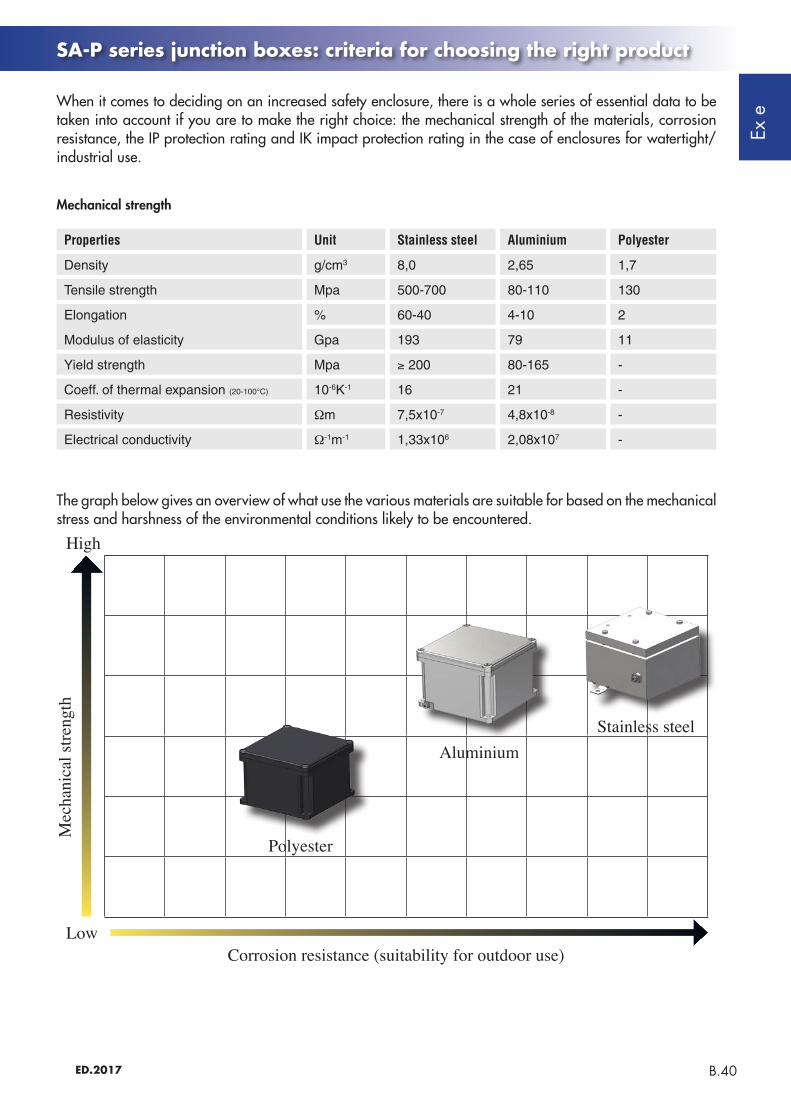
When it comes to deciding on an increased safety enclosure, there is a whole series of essential data to be taken into account if you are to make the right choice: the mechanical strength of the materials, corrosion resistance, the IP protection rating and IK impact protection rating in the case of enclosures for watertight/ industrial use.
SA-P series junction boxes: criteria for choosing the right product
Mechanical strength
The graph below gives an overview of what use the various materials are suitable for based on the mechanical stress and harshness of the environmental conditions likely to be encountered.
Mec
hani
cal s
treng
th
High
Low
Polyester
AluminiumStainless steel
Corrosion resistance (suitability for outdoor use)
Properties Unit Stainless steel Aluminium Polyester
Density g/cm3 8,0 2,65 1,7
Tensile strength Mpa 500-700 80-110 130
Elongation % 60-40 4-10 2
Modulus of elasticity Gpa 193 79 11
Yield strength Mpa ≥ 200 80-165 -
Coeff. of thermal expansion (20-100°C) 10-6K-1 16 21 -
IP PROTECTION RATINGS (IEC 529, EN 60529-4, CEI 70-1 ed. 11/92) The table gives protection ratings in accordance with standard CEI 70-1 ed. 11/92. Ratings are identified by the acronym IP followed by 2 digits, to which 2 letters may be added, indicating the degree to which persons are protected against access or other properties There is some variation in the application of ratings 7 and 8 relating to the ingress of liquids, with these ratings not always meaning that the item is suitable for lower levels (whereas IP rating x4 also covers the lower levels).
IMPACT PROTECTION RATINGSThis classification shows the acceptable level of strength, when evaluating a product's safety, and is mainly employed in relation to testing on electromechanical products.
1ST DIGITPROTECTION AGAINST SOLID OBJECTS
2ND DIGITPROTECTION AGAINST MOISTURE
PROTECTION AGAINST EXTERNAL MECHANICAL IMPACT *
0 0 IK00
IK06
IK03
IK08
IK01
IK07
IK05
IK09
IK10
3 3
1 1
4 4
2 2
5 5
7
6 6
8
Not protected Not protected
Not protected
Protected against impact energy of 1J
Protected against im-pact energy of 0.35J
Protected against impact energy of 5J
Protected against im-pact energy of 0.15J
Protected against impact energy of 2J
Protected against impact energy of 0.7J
Protected against impact energy of 10J
Protected against impact energy of 20J
Protected against solid objects greater than 50mm in Ø
Protected against vertically falling drops of water
Protected against solid objects greater than 12mm in Ø
Protected against rain when tilted up to 15°
Protected against solid objects greater than 2.5mm in Ø
Protected against rain when tilted up to 60°
Protected against solid objects greater than 1mm in Ø
Protected against splash-ing water
Protected against dust
Protected against jets of water from all directions
Totally protected against the ingress of dust
Protected against heavy seas
Protected against the effects of im-mersion
Protected against the effects of con-tinuous immersion
0.25 kg
0.25 kg
0.25 kg
0.25 kg
0.5 kg
1.7 kg
5 kg
5 kg
5.6 cm
14 cm
28 cm
40 cm
40 cm
30 cm
20 cm
40 cm
ADDITIONAL LETTER**
OPTIONAL LETTER
ABCD
HMSW
Protected against access with the back of the hand
High-voltage device
Protected against access with a finger
Tested against the harmful effects of water ingress with the equipment running
Protected against access with a tool
Tested against the harmful effects of water ingress with the equipment not running
Protected against access with a wire
Suitable for use in specified atmos-pheric conditions
* As per IEC EN 50102: 1996-05; IEC EN 60078-2-7-5: 1998-09.
** Optional letter describing protection against access by persons. Only used if protection against access to hazardous parts is greater than that indicated by the first digit, or if only protection against access to hazardous parts is given and an X is used in place of the first digit.
Protection ratings
Ex e
B.42ED.2017
SA-...P series Polyester junction boxes (Ex e) and (Ex i)
SA...P series junction boxes are made from fibreglass-reinforced polyester. Because they are highly resistant to contamination from fuel oils and mechanical shock, in addition to being lightweight and practical, they can be installed in all industrial plants, especially those where there is a potential risk of explosion and/or fire due to the presence of combustible gases or dust, classified as Zone 1, 2, 21 and 22. The enclosures have special holes made in the base for easy wall mounting. The lid features a silicone gasket that is resistant to low and high temperatures and comes complete with AISI 304 stainless steel screws, which are arranged around the outside of the lid to ensure a tight seal with the IP66 rating. SA...P series enclosures are mainly used as junction boxes/for routing cables for analogue or digital signals and/or for control and monitoring associated with equipment such as motors, fans, pumps and/or for giving physical readings such as flow rate, level, pressure, temperature, current, etc.. Terminal strips can be arranged inside the enclosure in various different configurations. The Cortem sales team will be able to advise you what enclosure best meets your needs based on: maximum number of terminals, number of holes per side, minimum distance involved and maximum power dissipation, ensuring everything is within the limits allowed by the certificate. 'Ex e' control, monitoring and signalling devices can be mounted on the lid in various different configurations based on your requirements and within the limits allowed by the certificate.
TYPE AND APPLICATIONChoosing an appropriate container is a key step in the project development process, making it essential to approach the decision systematically, evaluating all variables methodically: where our equipment is being installed, the environmental conditions on site, what degree of protection it must have, what space is available and how it is due to be set up. Once you have processed all this information, you should be able to determine which product best suits the design requirements in question.ENVIRONMENTAL CONDITIONSThe first factor to consider is what environmental conditions the equipment is going to be installed in, whether it will be indoors or outside, and what environments it is required to operate in: pharmaceutical, chemical, petrochemical, food, shipbuilding, agricultural industries...DIMENSIONSThe size of the space available for inserting the enclosure and its components must be determined early on in the process.DESIGNTaking into account the technical aspect, product design and appearance is also important in ensuring the equipment to be installed in the enclosure is integrated seamlessly. A Cortem team of experts is on hand every day to address your questions and come up with the best solutions.Cortem enclosures have passed:- IP protection testing;- IK strength testing;- vibration and impact resistance testing;- salt mist testing for corrosion resistance;- heat resistance testing;- low temperature resistance testing.
Application sectors:Oil refineries Chemical and
petrochemical plants
Onshore plants
Offshore plants
Low temperatures
Fuel depots
Ships and shipbuilding
Wastewater treatment
Cortem Group labels its products with a non-removable adhesive label featuring a hologram and an alphanumerical univocal code, as a safety measure against the illegal sale of fakes so that all the products are guaranteed as original. Non-compliance with the International standards entails serious risks for the environment, especially for those working daily on the plants.
Ex e
B.43 ED.2017
SA-...P series Polyester junction boxes (Ex e) and (Ex i)
AMBIENT TEMPERATURE TEMPERATURE CLASS MAXIMUM SURFACE TEMPERATURE
MAXIMUM TERMINAL OPERATING TEMPERATURE
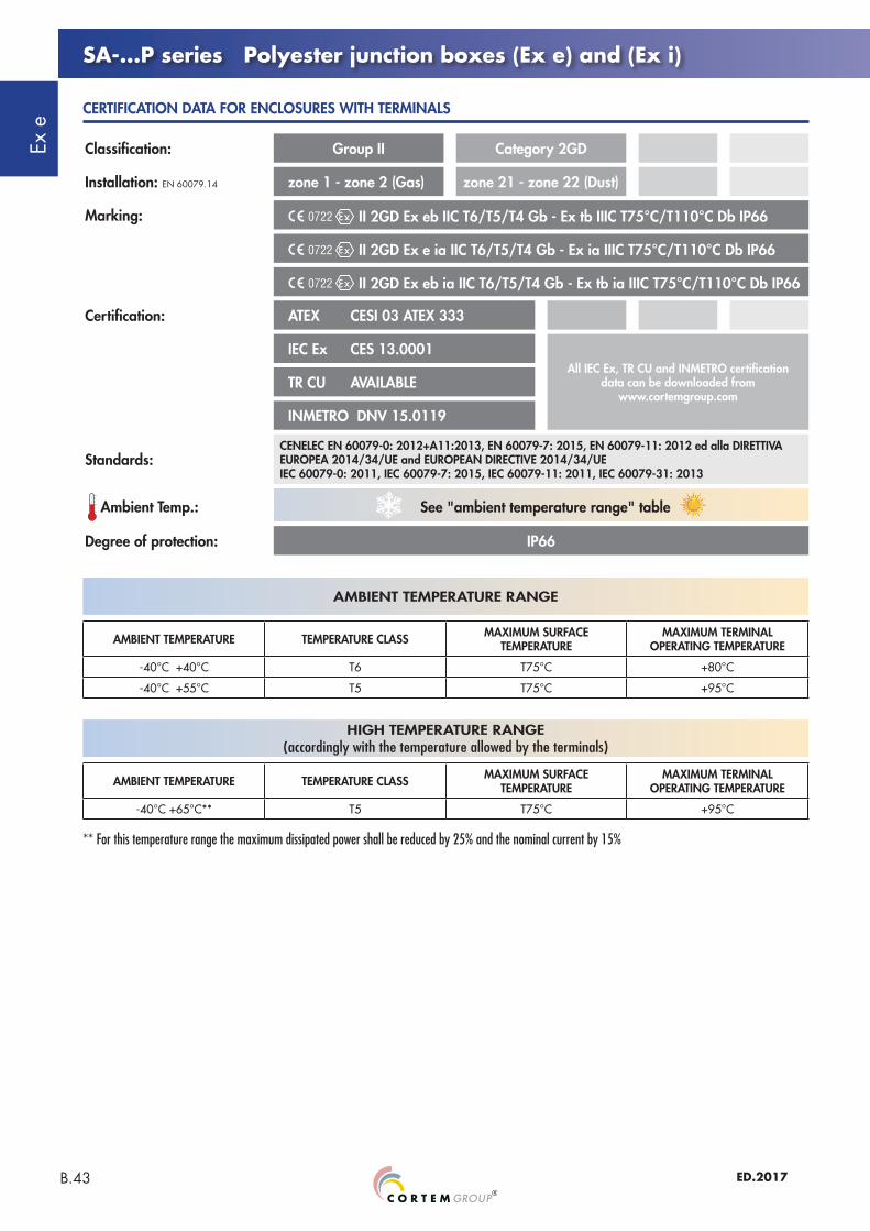
-40°C +40°C T6 T75°C +80°C
-40°C +55°C T5 T75°C +95°C
AMBIENT TEMPERATURE RANGE
** For this temperature range the maximum dissipated power shall be reduced by 25% and the nominal current by 15%
CERTIFICATION DATA FOR ENCLOSURES WITH TERMINALS
HIGH TEMPERATURE RANGE(accordingly with the temperature allowed by the terminals)
AMBIENT TEMPERATURE TEMPERATURE CLASS MAXIMUM SURFACE TEMPERATURE
MAXIMUM TERMINAL OPERATING TEMPERATURE
-40°C +65°C** T5 T75°C +95°C
Classification: Group II Category 2GD
Installation: EN 60079.14 zone 1 - zone 2 (Gas) zone 21 - zone 22 (Dust)
Marking: II 2GD Ex eb IIC T6/T5/T4 Gb - Ex tb IIIC T75°C/T110°C Db IP66
II 2GD Ex e ia IIC T6/T5/T4 Gb - Ex ia IIIC T75°C/T110°C Db IP66
II 2GD Ex eb ia IIC T6/T5/T4 Gb - Ex tb ia IIIC T75°C/T110°C Db IP66
Certification: ATEX CESI 03 ATEX 333
IEC Ex CES 13.0001All IEC Ex, TR CU and INMETRO certification
data can be downloaded from www.cortemgroup.com
TR CU AVAILABLE
INMETRO DNV 15.0119
Standards:CENELEC EN 60079-0: 2012+A11:2013, EN 60079-7: 2015, EN 60079-11: 2012 ed alla DIRETTIVA EUROPEA 2014/34/UE and EUROPEAN DIRECTIVE 2014/34/UEIEC 60079-0: 2011, IEC 60079-7: 2015, IEC 60079-11: 2011, IEC 60079-31: 2013
Ambient Temp.: See "ambient temperature range" table
Degree of protection: IP66
Ex e
B.44ED.2017
SA-...P series Polyester junction boxes (Ex e) and (Ex i)
CERTIFICATION DATA OF ENCLOSURES FOR CONTROL, MONITORING AND SIGNALLING UNITS
Classification: Group II Category 2GD
Installation: EN 60079.14 zone 1 - zone 2 (Gas) zone 21 - zone 22 (Dust)
Marking: II2GD - Ex de IIC T6/T5 Gb - Ex tb IIIC T85°C/T100°C Db - IP66
II2GD - Ex e IIC T6/T5 Gb - Ex tb IIIC T85°C/T100°C Db - IP66(When on the box is installed only ammeter or voltmeter type B-0140)
Certification: ATEX CESI 03 ATEX 115
IEC Ex CES 11.0032
All IEC Ex, TR CU and INMETRO certification data can be downloaded from
www.cortemgroup.comTR CU AVAILABLE
INMETRO DNV 15.0125
Standards:CENELEC EN 60079-0: 2012, EN 60079-1: 2007, EN 60079-7: 2007, N 60079-31: 2009, EN 60529: 1991 and EUROPEAN DIRECTIVE 2014/34/UEIEC 60079-0: 2011-06, IEC 60079-7: 2006-07, IEC 60079-11: 2008-11, IEC 60529: 2001
Ambient Temp.: -40°C +40°C With temperature class T6 and maximum surface temperature T85°C.
-40°C +55°C With temperature class T5 and maximum surface temperature T100°C.
Degree of protection: IP66
CERTIFICATION DATA OF ENCLOSURES WITH EQUIPMENT (FIELDBUS, PROXIMITOR, HEATER...)
Classification: Group II Category 2GD
Installation: EN 60079.14 zone 1 - zone 2 (Gas) zone 21 - zone 22 (Dust)
Marking: II2GD - Ex eb IIC T6/T5 Gb - Ex tb IIIC T85°C/T100°C Db - IP66
II2(1)GD - Ex eb ib mb [ia Ga] IIC T4 Gb - Ex tb [ia Da] IIIC T85°C Db IP66
Certification: ATEX CML 16 ATEX 3163X
IEC Ex CML 16.0074X All IEC Ex certification data can be downloaded from www.cortemgroup.com
Standards:CENELEC EN 60079-0: 2012, EN 60079-7: 2015, EN 60079-28: 2015, EN 60079-31: 2014 and EUROPEAN DIRECTIVE 2014/34/UEIEC 60079-0: 2011-06, IEC 60079-7: 2015, IEC 60079-28: 2015, IEC 60079-31:2013
Ambient Temp.: -40°C (-50°C) +40°C With temperature class T6 and maximum surface temperature T85°C.
-40°C (-50°C) +55°C With temperature class T5 and maximum surface temperature T100°C.
Body and lid: Made from polyester resin in black with antistatic propertiesImpact protection rating: IK10Gasket: Acid, hydrocarbon and high temperature-resistant silicone, located between body and
lidMounting: Polyester feet for M6 screwsCertification label: Aluminium plate riveted into lidBolts and screws: Stainless steel captive variety
GENERAL MECHANICAL PROPERTIES
OVERVIEW OF SIZES
SA-...P series Polyester junction boxes (Ex e) and (Ex i)
Ex e
B.46ED.2017
SA-...P series Polyester junction boxes (Ex e) and (Ex i)
As required by the current standard, holes can be drilled by Cortem or by authorized partners who hold a production notification in accordance with ATEX Directive .
Ex e
B.48ED.2017
Ex II 2GD Ex eb IIC T... Gb - Ex tb IIIC T... Db IP66
Ex II 2GD Ex ia IIC T... Gb - Ex ia IIIC T... Db IP66
Ex II 2GD Ex eb ia IIC T... Gb - Ex tb ia IIIC T... Db IP66
SA-...P series Features of junction boxes with terminals
These enclosures are customized based on size, on the number of terminals or cables they are due to accommodate, or taking into account the number of cable entries and cabling requirements inside a system. Hence we can produce tailor-made solutions as long as you provide us with the appropriate parameters required at the quote request stage, such as the number of cable glands, unions or sealing fittings to be installed, so that we can determine the most suitable size of enclosure. All terminals can be fitted with your requested accessories and mounted on special rails that are fastened to the enclosure's internal mounting plates. Terminal strips can be arranged in various ways, as specified by the customer and always within the limits allowed by the certificate. The options are vertical, horizontal, in a number of rows, or on different levels using suitable spacers.
Marking Terminal type Description
Plugs with nickel-plated brass lock nut
Brass continuity plates for earthing
Cable glands with nickel-plated brass lock nut
Modular terminals installed directly on rails mounted on mounting plate or directly on continuity plate
Enclosures containing increased safety terminals to standard EN 60079-7
Ex e terminals only
Enclosures containing increased safety terminals and intrinsic safety terminals to standards EN 60079-7 and EN 60079-11
Ex e and Ex i terminals
Enclosures containing intrinsic safety terminals to standard EN 60079-11; enclosures are still category 2
Ex i terminals only
ELECTRICAL FEATURES
Standard applicationsSignal circuits applications
T6/T75°C max. Tamb +60°C
T4/T100°C max. Tamb +85°C
Rated voltage: 1000 Vac/dc - -
Rated current: 312 A 1 A for exec. Ex eb100 mA for exec. Ex ia
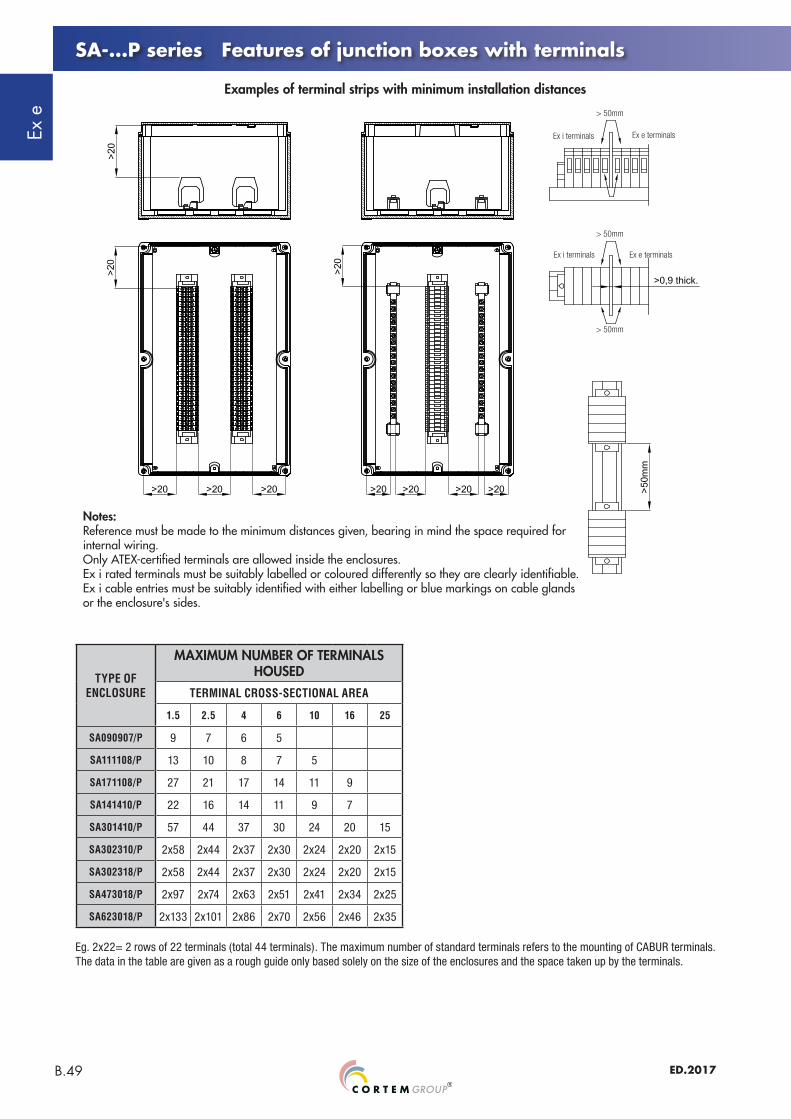
SA-...P series Features of junction boxes with terminals
Examples of terminal strips with minimum installation distances
Notes:Reference must be made to the minimum distances given, bearing in mind the space required for internal wiring.Only ATEX-certified terminals are allowed inside the enclosures.Ex i rated terminals must be suitably labelled or coloured differently so they are clearly identifiable.Ex i cable entries must be suitably identified with either labelling or blue markings on cable glands or the enclosure's sides.
> 50mm
> 50mm
> 50mm
Ex i terminals
Ex i terminals
Ex e terminals
Ex e terminals
Eg. 2x22= 2 rows of 22 terminals (total 44 terminals). The maximum number of standard terminals refers to the mounting of CABUR terminals.The data in the table are given as a rough guide only based solely on the size of the enclosures and the space taken up by the terminals.
TYPE OFENCLOSURE
MAXIMUM NUMBER OF TERMINALS HOUSED
TERMINAL CROSS-SECTIONAL AREA
1.5 2.5 4 6 10 16 25
SA090907/P 9 7 6 5
SA111108/P 13 10 8 7 5
SA171108/P 27 21 17 14 11 9
SA141410/P 22 16 14 11 9 7
SA301410/P 57 44 37 30 24 20 15
SA302310/P 2x58 2x44 2x37 2x30 2x24 2x20 2x15
SA302318/P 2x58 2x44 2x37 2x30 2x24 2x20 2x15
SA473018/P 2x97 2x74 2x63 2x51 2x41 2x34 2x25
SA623018/P 2x133 2x101 2x86 2x70 2x56 2x46 2x35
Ex e
B.50ED.2017
SA-...P series Features of junction boxes with terminals
The permissible maximum power dissipation, in order to retain a T6 temperature class with an ambient temperature up to +40°C or T5 class with an ambient temperature of 55°C, is not to exceed the values given in the tables below. For an ambient temperature of +60°C, maximum power dissipation must be reduced by 25%, and rated current reduced by 15%. The maximum current values for terminal strips used for low-voltage circuits (signalling units) with a T6 temperature class and maximum ambient temperature of +60°C or T4 and maximum ambient temperature +65°C and +85°C, are as follows: - 1A for Ex e circuits;- 100mA for Ex ia circuits.The values given in the tables on the coming pages refer to the maximum number of conductors allowed for a conductor with a given cross-sectional area and a given maximum current. All incoming wires and active internal links (made by wires) count as wires. Earth connections (i.e. passive connections) do not count.When DIN/Omega rails are installed on the internal mounting plate (instead of using the relevant mounting plate fastening holes), the number of terminals may be slightly less than the number given in the tables.Other types of terminals can be used up to the space limit of the box. Whatever the case, all terminals used shall be ATEX and/or IEC Ex certified. Size 35mm2 terminals can be used for conductors with a cross-sectional area of 25mm2.The maximum number of terminals and maximum number of rows given in the tables is an indicative value: you must take into account the cable entries on the sides of the boxes. The internal overall dimensions of cable glands/lock nuts and the overall dimensions of conductors must be taken into consideration to allow for wiring.In some cases, it may be necessary to reduce the number of terminals or the number of rows.Example of how to calculate the maximum number of conductors.Referring to table SA141410/P: 6 conductors with 6mm2 cross-section with 26A continuous current is the limit of this box.
Consequently, box SA141410/P is suitable for containing 3 x 6mm2 terminals (2 conductors for each terminal) with a max. current of 26A. There is space for 11 x 6mm2 terminals in the box. The remaining 8 terminals (11-3) can be added and used for low-current circuits indicated in area "1" of the table (in this case max. 8-10A).
Combined mounting for electrical circuits with different sized cables is possible provided the values given are used proportionally.For example:
Nominal X-sect. area (mm2) Current (A) Quantity Capacity
2,5 8 16 (di 46) 34,8%
4 11 12 (di 36) 33,3%
10 26 4 (di 13) 30,8%
Totale 98,9% <100%
Enclosure P[W]
Maximum current [A] per conductor cross-sectional area in mm2
1.5 2.5 4 6 10 16 25
SA090907/P 5.6 11 15 21 26 37 49 67
SA111108/P 7.5 11 15 21 26 37 49 67
SA171108/P 8.8 11 15 21 26 37 49 67
SA141410/P 7.8 11 15 21 26 37 49 67
SA301410/P 15 11 15 21 26 37 49 67
SA302310/P 16 11 15 21 26 37 49 67
SA302318/P 17.5 11 15 21 26 37 49 67
SA473018/P 42 11 15 21 26 37 49 67
SA623018/P 52 11 15 21 26 37 49 67
Enclosure P[W]
Maximum current [A] per conductor cross-sectional area in mm2
1.5 2.5 4 6 10 16 25
SA090907/P 4.2 9 12 17 22 31 41 57
SA111108/P 5.6 9 12 17 22 31 41 57
SA171108/P 6.6 9 12 17 22 31 41 57
SA141410/P 5.8 9 12 17 22 31 41 57
SA301410/P 11.2 9 12 17 22 31 41 57
SA302310/P 12 9 12 17 22 31 41 57
SA302318/P 13.1 9 12 17 22 31 41 57
SA473018/P 31.5 9 12 17 22 31 41 57
SA623018/P 39 9 12 17 22 31 41 57
Table showing maximum power dissipation and current for ambient temperature +40°C and +55°C
Table showing maximum power dissipation and current for ambient temperature +60°C
Ex e
B.51 ED.2017
SA-...P series Features of junction boxes with terminals
Maximum power dissipation with T6 temperature class must not exceed 7.8W
Maximum power dissipation with T6 temperature class must not exceed 7.5W
Maximum power dissipation with T6 temperature class must not exceed 5.6W
Maximum power dissipation with T6 temperature class must not exceed 16W
Maximum power dissipation with T6 temperature class must not exceed 52W
Maximum power dissipation with T6 temperature class must not exceed 8.8W
Maximum power dissipation with T6 temperature class must not exceed 17.5W
Maximum power dissipation with T6 temperature class must not exceed 15W
Maximum power dissipation with T6 temperature class must not exceed 42W
Tables showing maximum number of conductors
(N° of terminals = n° of conductors)2
: In this section of the table that has not been filled in, once you have followed the instructions and complied with the values given for the enclosure's internal wiring, you can add as many terminals as you want up to the space limit of the box.
: Any wiring that falls within this section of the table that has not been filled in is not covered by the certificate.
"C. No." row: the values given refer to the maximum number of CABUR terminals physically allowed inside the relevant enclosure. These values are expressed as the product of the rows multiplied by the number of terminals on each row."W. No." row: the same as above, but this time referring to Weidmuller terminals.The terminal brands are mentioned just to give an idea of the quantity of terminals that can be housed inside the enclosure.The other values given in the cells along the table's diagonal define the maximum number of conductors allowed, based on their cross-sectional area and maximum current.
Instructions for determining which enclosure is best suited based on the planned number of conductors and terminals.
Ex e
B.52ED.2017
SA-...P series Features of junction boxes with terminals
Codes of terminals used to determine maximum number of terminalsThe other values given in the cells along the table's diagonal define the maximum number of conductors allowed, based on their cross-sectional area and maximum current.
ATEX - IECEx label for terminal enclosures Data filled in:
1. year of manufacture2. serial number3. product code4. ambient temperature5. temperature class and maximum surface 6. temperature of cables7. electrical specs per certificate
Continuity plate for all four enclosure sides
Continuity plate for single enclosure side
Enclosure Plate CodePlate Code
Long side Short side
SA090907/P B-388 B-455
SA111108/P B-389 B-456
SA141410/P B-390 B-457
SA171108/P B-391 B-458 B-456
SA301410/P B-392 B-459 B-457
SA302310/P B-393 B-459 B-460
SA302318/P B-394 B-461 B-462
SA473018/P B-395 (2x) B-462 B-461
SA623018/P - (2x) B-463 B-463
DON'T FORGET TO ORDER THE ACCESSORIESExample: Enclosure type
SA202012 +Internal mounting plate
B20-229Cable glands,
unions+ + other...see key
RICAMBIO
ACCESSORIO
Ex e
B.53 ED.2017
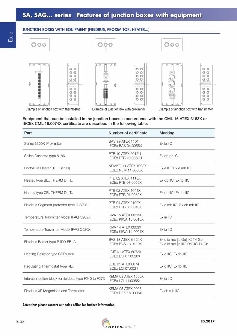
SA, SAG... series Features of junction boxes with equipment
Equipment that can be installed in the junction boxes in accordance with the CML 16 ATEX 3163X or IECEx CML 16.0074X certificate are described in the following table:
JUNCTION BOXES WITH EQUIPMENT (FIELDBUS, PROXIMITOR, HEATER...)
Example of junction box with thermostat Example of junction box with proximitor Example of junction box with transmitter
Attention: please contact our sales office for further information.
Part Number of certificate Marking
Series 3300Xl ProximitorBAS 99 ATEX 1101IECEx BAS 04.0055X
Ex ia IIC
Splice Cassette type 8186PTB 10 ATEX 2015UIECEx PTB 10.0060U
Ex op pr IIC
Enclosure Heater (TEF Series)NEMKO 11 ATEX 1098XIECEx NEM 11.0005X
Hinges (two each type): B-0105Breather and drain valve: ECD-210S
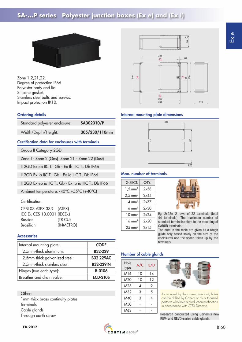
Eg. 2x22= 2 rows of 22 terminals (total 44 terminals). The maximum number of standard terminals refers to the mounting of CABUR terminals.The data in the table are given as a rough guide only based solely on the size of the enclosures and the space taken up by the terminals.
II 2GD Ex eb ia IIC T.. Gb - Ex tb ia IIIC T.. Db IP66
Ambient temperature: -40°C +55°C (+40°C)
CESI 03 ATEX 333 (ATEX)IEC Ex CES 13.0001 (IECEx)Russian (TR CU)Brasilian (INMETRO)
X-SECT. QTY.
1.5 mm2 1x9
2.5 mm2 1x7
4 mm2 1x6
6 mm2 1x5
10 mm2 -
16 mm2 -
25 mm2 -
Hole type A/C B/D
M16 1 1
M20 1 1
M25 1 1
M32 - -
M40 - -
M50 - -
M63 - -
Ordering details
Certification data for enclosures with terminals
Max. number of terminals
Number of cable glands
Accessories
Research conducted using Cortem's new REV- and REVD-series cable glands.
As required by the current standard, holes can be drilled by Cortem or by authorized partners who hold a production notification in accordance with ATEX Directive .
Internal mounting plate dimensions
Zone 1,2,21,22.Degree of protection IP66. Polyester body and lid.Silicone gasket.Stainless steel bolts and screws.Impact protection IK10.
SA-...P series Polyester junction boxes (Ex e) and (Ex i)
Hinges (two each type): B-0105Breather and drain valve: ECD-210S
Eg. 2x22= 2 rows of 22 terminals (total 44 terminals). The maximum number of standard terminals refers to the mounting of CABUR terminals.The data in the table are given as a rough guide only based solely on the size of the enclosures and the space taken up by the terminals.
II 2GD Ex eb ia IIC T.. Gb - Ex tb ia IIIC T.. Db IP66
Ambient temperature: -40°C +55°C (+40°C)
CESI 03 ATEX 333 (ATEX)IEC Ex CES 13.0001 (IECEx)Russian (TR CU)Brasilian (INMETRO)
X-SECT. QTY.
1.5 mm2 1x13
2.5 mm2 1x10
4 mm2 1x8
6 mm2 1x7
10 mm2 1x5
16 mm2 -
25 mm2 -
Hole type A/C B/D
M16 3 3
M20 2 2
M25 1 1
M32 1 1
M40 - -
M50 - -
M63 - -
Ordering details
Certification data for enclosures with terminals
Max. number of terminals
Number of cable glands
Accessories
Research conducted using Cortem's new REV- and REVD-series cable glands.
As required by the current standard, holes can be drilled by Cortem or by authorized partners who hold a production notification in accordance with ATEX Directive .
Internal mounting plate dimensions
Zone 1,2,21,22.Degree of protection IP66. Polyester body and lid.Silicone gasket.Stainless steel bolts and screws.Impact protection IK10.
SA-...P series Polyester junction boxes (Ex e) and (Ex i)
Ex e
B.57 ED.2017
Standard polyester enclosure: SA171108/P
Width/Depth/Height: 170/110/83mm
Group II Category 2GD
Zone 1- Zone 2 (Gas) Zone 21 - Zone 22 (Dust)
Certification:
CESI 03 ATEX 333 (ATEX)IEC Ex CES 13.0001 (IECEx)Russian (TR CU)Brasilian (INMETRO)
Ordering details
Certification data for enclosures with terminals
Max. number of terminals
Number of cable glands
Accessories
Research conducted using Cortem's new REV- and REVD-series cable glands.
As required by the current standard, holes can be drilled by Cortem or by authorized partners who hold a production notification in accordance with ATEX Directive .
Hinges (two each type): B-0105Breather and drain valve: ECD-210S
Eg. 2x22= 2 rows of 22 terminals (total 44 terminals). The maximum number of standard terminals refers to the mounting of CABUR terminals.The data in the table are given as a rough guide only based solely on the size of the enclosures and the space taken up by the terminals.
Other:
X-SECT. QTY.
1.5 mm2 1x27
2.5 mm2 1x21
4 mm2 1x17
6 mm2 1x14
10 mm2 1x11
16 mm2 1x9
25 mm2 -
Hole type A/C B/D
M16 3 8
M20 2 5
M25 1 3
M32 1 2
M40 - -
M50 - -
M63 - -
Internal mounting plate dimensions
Ambient temperature: -40°C +55°C (+40°C)
SA-...P series Polyester junction boxes (Ex e) and (Ex i)
Zone 1,2,21,22.Degree of protection IP66. Polyester body and lid.Silicone gasket.Stainless steel bolts and screws.Impact protection IK10.
II 2GD Ex eb ia IIC T.. Gb - Ex tb ia IIIC T.. Db IP66
Ex e
B.58ED.2017
Width/Depth/Height: 147/147/100mm
Standard polyester enclosure: SA141410/P
Group II Category 2GD
Zone 1- Zone 2 (Gas) Zone 21 - Zone 22 (Dust)
Certification:
CESI 03 ATEX 333 (ATEX)IEC Ex CES 13.0001 (IECEx)Russian (TR CU)Brasilian (INMETRO)
Ordering details
Certification data for enclosures with terminals
Max. number of terminals
Number of cable glands
Accessories
Research conducted using Cortem's new REV- and REVD-series cable glands.
As required by the current standard, holes can be drilled by Cortem or by authorized partners who hold a production notification in accordance with ATEX Directive .
Hinges (two each type): B-0105Breather and drain valve: ECD-210S
Eg. 2x22= 2 rows of 22 terminals (total 44 terminals). The maximum number of standard terminals refers to the mounting of CABUR terminals.The data in the table are given as a rough guide only based solely on the size of the enclosures and the space taken up by the terminals.
Other:
Hole type A/C B/D
M16 6 6
M20 6 6
M25 3 3
M32 2 2
M40 1 1
M50 - -
M63 - -
Internal mounting plate dimensions
Ambient temperature: -40°C +55°C (+40°C)
SA-...P series Polyester junction boxes (Ex e) and (Ex i)
Zone 1,2,21,22.Degree of protection IP66. Polyester body and lid.Silicone gasket.Stainless steel bolts and screws.Impact protection IK10.
Hinges (two each type): B-0106Breather and drain valve: ECD-210S
Eg. 2x22= 2 rows of 22 terminals (total 44 terminals). The maximum number of standard terminals refers to the mounting of CABUR terminals.The data in the table are given as a rough guide only based solely on the size of the enclosures and the space taken up by the terminals.
Other:
Standard polyester enclosure: SA301410/P
Width/Depth/Height: 305/147/110mm
Group II Category 2GD
Zone 1- Zone 2 (Gas) Zone 21 - Zone 22 (Dust)
Certification:
CESI 03 ATEX 333 (ATEX)IEC Ex CES 13.0001 (IECEx)Russian (TR CU)Brasilian (INMETRO)
Ordering details
Certification data for enclosures with terminals
Max. number of terminals
Number of cable glands
Accessories
Research conducted using Cortem's new REV- and REVD-series cable glands.
As required by the current standard, holes can be drilled by Cortem or by authorized partners who hold a production notification in accordance with ATEX Directive .
Hole type A/C B/D
M16 6 14
M20 6 12
M25 3 9
M32 2 5
M40 1 4
M50 1 3
M63 - -
Internal mounting plate dimensions
Ambient temperature: -40°C +55°C (+40°C)
SA-...P series Polyester junction boxes (Ex e) and (Ex i)
Zone 1,2,21,22.Degree of protection IP66. Polyester body and lid.Silicone gasket.Stainless steel bolts and screws.Impact protection IK10.
Hinges (two each type): B-0106Breather and drain valve: ECD-210S
Eg. 2x22= 2 rows of 22 terminals (total 44 terminals). The maximum number of standard terminals refers to the mounting of CABUR terminals.The data in the table are given as a rough guide only based solely on the size of the enclosures and the space taken up by the terminals.
Other:
Width/Depth/Height: 305/230/110mm
Standard polyester enclosure: SA302310/P
Group II Category 2GD
Zone 1- Zone 2 (Gas) Zone 21 - Zone 22 (Dust)
Certification:
CESI 03 ATEX 333 (ATEX)IEC Ex CES 13.0001 (IECEx)Russian (TR CU)Brasilian (INMETRO)
Ordering details
Certification data for enclosures with terminals
Max. number of terminals
Number of cable glands
Internal mounting plate dimensions
Accessories
Research conducted using Cortem's new REV- and REVD-series cable glands.
As required by the current standard, holes can be drilled by Cortem or by authorized partners who hold a production notification in accordance with ATEX Directive .
Hole type A/C B/D
M16 10 14
M20 10 12
M25 4 9
M32 3 5
M40 3 4
M50 - -
M63 - -
Ambient temperature: -40°C +55°C (+40°C)
SA-...P series Polyester junction boxes (Ex e) and (Ex i)
Zone 1,2,21,22.Degree of protection IP66. Polyester body and lid.Silicone gasket.Stainless steel bolts and screws.Impact protection IK10.
II 2GD Ex eb ia IIC T.. Gb - Ex tb ia IIIC T.. Db IP66
Ex e
B.61 ED.2017
Standard polyester enclosure: SA302318/P
Width/Depth/Height: 305/230/190mm
Group II Category 2GD
Zone 1- Zone 2 (Gas) Zone 21 - Zone 22 (Dust)
Certification:
CESI 03 ATEX 333 (ATEX)IEC Ex CES 13.0001 (IECEx)Russian (TR CU)Brasilian (INMETRO)
Ordering details
Certification data for enclosures with terminals
Max. number of terminals
Number of cable glands
Internal mounting plate dimensions
Accessories
Research conducted using Cortem's new REV- and REVD-series cable glands.
As required by the current standard, holes can be drilled by Cortem or by authorized partners who hold a production notification in accordance with ATEX Directive .
Hinges (two each type): B-0106Breather and drain valve: ECD-210S
Eg. 2x22= 2 rows of 22 terminals (total 44 terminals). The maximum number of standard terminals refers to the mounting of CABUR terminals.The data in the table are given as a rough guide only based solely on the size of the enclosures and the space taken up by the terminals.
Other:
Ambient temperature: -40°C +55°C (+40°C)
SA-...P series Polyester junction boxes (Ex e) and (Ex i)
Zone 1,2,21,22.Degree of protection IP66. Polyester body and lid.Silicone gasket.Stainless steel bolts and screws.Impact protection IK10.
II 2GD Ex eb ia IIC T.. Gb - Ex tb ia IIIC T.. Db IP66
Ex e
B.62ED.2017
Width/Depth/Height: 470/305/195mm
Standard polyester enclosure: SA473018/P
Group II Category 2GD
Zone 1- Zone 2 (Gas) Zone 21 - Zone 22 (Dust)
Certification:
CESI 03 ATEX 333 (ATEX)IEC Ex CES 13.0001 (IECEx)Russian (TR CU)Brasilian (INMETRO)
Ordering details
Certification data for enclosures with terminals
Max. number of terminals
Number of cable glands
Internal mounting plate dimensions
Accessories
Research conducted using Cortem's new REV- and REVD-series cable glands.
As required by the current standard, holes can be drilled by Cortem or by authorized partners who hold a production notification in accordance with ATEX Directive .
Hinges (two each type): B-0106Breather and drain valve: ECD-210S
Eg. 2x22= 2 rows of 22 terminals (total 44 terminals). The maximum number of standard terminals refers to the mounting of CABUR terminals.The data in the table are given as a rough guide only based solely on the size of the enclosures and the space taken up by the terminals.
Other:
Hole type A/C B/D
M20 24 36
M25 18 24
M32 14 18
M40 8 12
M50 8 12
M63 3 4
Ambient temperature: -40°C +55°C (+40°C)
SA-...P series Polyester junction boxes (Ex e) and (Ex i)
Zone 1,2,21,22.Degree of protection IP66. Polyester body and lid.Silicone gasket.Stainless steel bolts and screws.Impact protection IK10.
Hinges (two each type): B-0106Breather and drain valve: ECD-210S
Eg. 2x22= 2 rows of 22 terminals (total 44 terminals). The maximum number of standard terminals refers to the mounting of CABUR terminals.The data in the table are given as a rough guide only based solely on the size of the enclosures and the space taken up by the terminals.
Other:
Standard polyester enclosure: SA623018/P
Width/Depth/Height: 620/305/185mm
Group II Category 2GD
Zone 1- Zone 2 (Gas) Zone 21 - Zone 22 (Dust)
Certification:
CESI 03 ATEX 333 (ATEX)IEC Ex CES 13.0001 (IECEx)Russian (TR CU)Brasilian (INMETRO)
Ordering details
Certification data for enclosures with terminals
Max. number of terminals
Number of cable glands
Internal mounting plate dimensions
Accessories
Research conducted using Cortem's new REV- and REVD-series cable glands.
As required by the current standard, holes can be drilled by Cortem or by authorized partners who hold a production notification in accordance with ATEX Directive .
Hole type A/C B/D
M20 24 48
M25 18 36
M32 14 28
M40 8 16
M50 8 12
M63 3 6
Ambient temperature: -40°C +55°C (+40°C)
SA-...P series Polyester junction boxes (Ex e) and (Ex i)
Zone 1,2,21,22.Degree of protection IP66. Polyester body and lid.Silicone gasket.Stainless steel bolts and screws.Impact protection IK10.
Notes:"e">12mm: standard version. Suitable for voltage U<800V"e">5mm: special versions. Suitable for voltage U<250V When determining enclosure size, what holes are drilled and what devices can be installed, we also need to take into account the space required for internal wiring and running the cables.
MINIMUM DISTANCES BETWEEN CORTEM Ex e CONTACTS (e.g. with reference to CESI 03 ATEX 115 certificate)
Rated voltage: 600 V ac/dcMax. current on contacts: 16 ARated frequency: 50 / 60Hz
ELECTRICAL FEATURES
Control, monitoring and signalling units are used to produce control boards that, when positioned near the electrical equipment being controlled, enable the electrical system to operate correctly and guarantee the safety of personnel when maintenance is being performed on the system. Because they are fitted with a Manual/Automatic selector, they allow operators to select the appropriate conditions to enable work to be performed entirely safely. They offer protection and control for electrical equipment and control circuits located in explosion hazard areas and in particularly aggressive environments. They are used to hold electrical equipment, such as switches, indicators, contactors, transformers, analogue and digital components, etc.... with the option of external control by using lid-mounted Cortem control and signalling devices, such as control levers, pushbuttons, indicator lights, etc.... Cortem designs, develops and supplies full cabling for one or more enclosures tailored to your specific requirements, producing panel boards - including even extremely complex solutions - and providing a full inspection and testing service on request.
1 2 3
4 5
7
6 9
8
Ex e
B.65 ED.2017
Notes:Minimum distances between devices worked out for use of standard 60x20 plates.Option of using up to 4 contacts per device for pushbutton M-0603 and selector M-0604.Option of using up to 2 contacts per device for emergency stop pushbutton M-0605.For more information, refer to the Ex e control, monitoring and signalling devices chapter.
TYPE OFENCLOSURE
Drilling areamm
SA090907/P 70x70
SA111108/P 90x90
SA171108/P 90x150
SA141410/P 127x127
SA301410/P 127x285
SA302310/P 210x285
SA302318/P 210x285
SA473018/P 285x450
SA623018/P 596x280
MINIMUM DISTANCES BETWEEN CORTEM Ex e DEVICES FOR PUSHBUTTON CONTROL STATIONS
Distances forindicator lights
Distances forammeter/voltmeter
Distances fordevices with 2 and/or 4 contacts
KEY
TYPE OF HOLES DRILLED
For ammeter/voltmeter
For indicator light
For control devices
4-contact device
2-contact device
Indicator light
Ammeter/voltmeter
Features of junction boxes for control, monitoring and signalling units