48
Alan Courtay March 7, 2016 Quasi-resonant Flyback Converter Simulation Saber Tutorial
Alan Courtay
March 7, 2016
Quasi-resonant Flyback Converter Simulation
Saber Tutorial
© 2016 Synopsys, Inc. 2
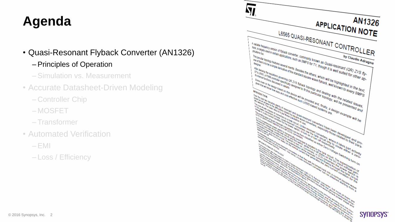
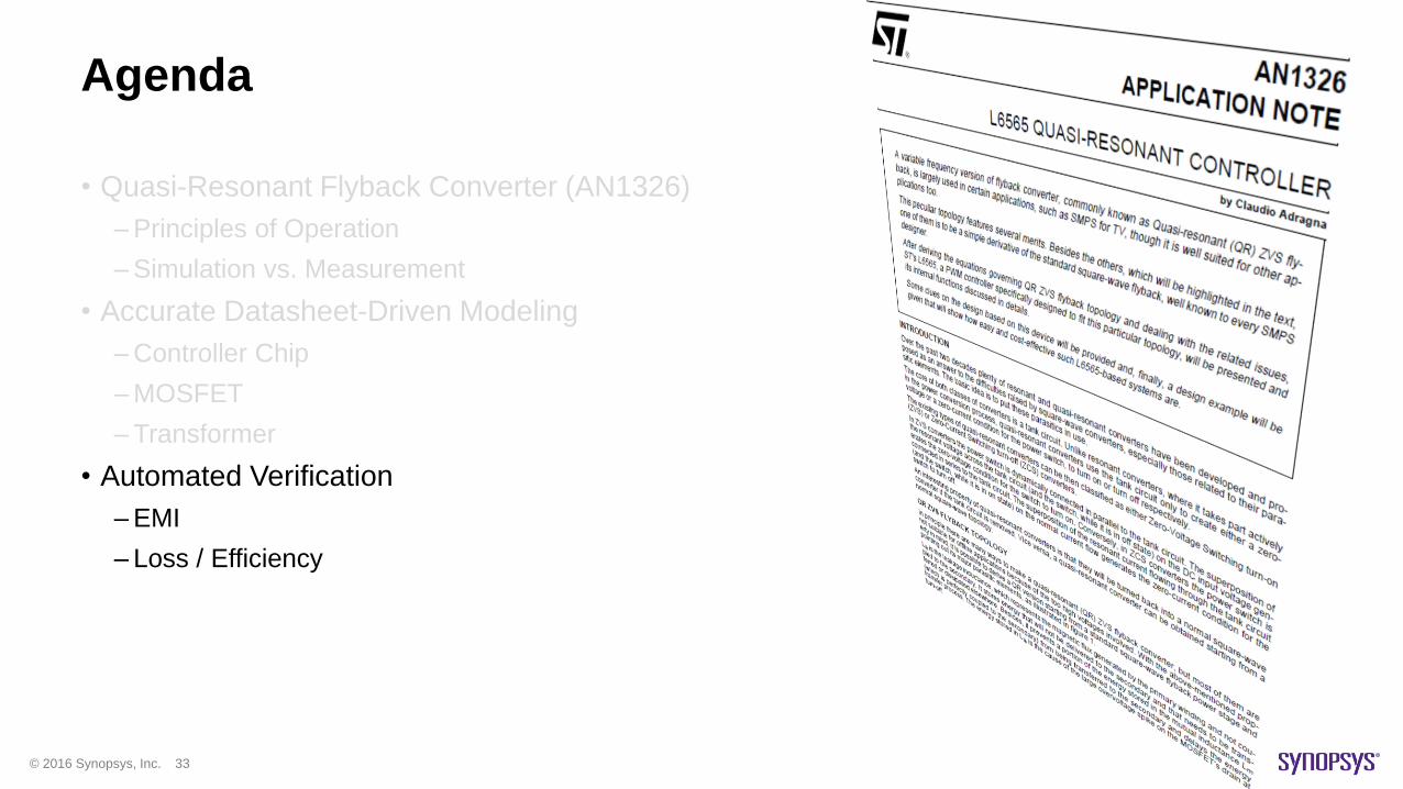
Agenda
• Quasi-Resonant Flyback Converter (AN1326)
–Principles of Operation
–Simulation vs. Measurement
• Accurate Datasheet-Driven Modeling
–Controller Chip
–MOSFET
–Transformer
• Automated Verification
–EMI
– Loss / Efficiency
© 2016 Synopsys, Inc. 3
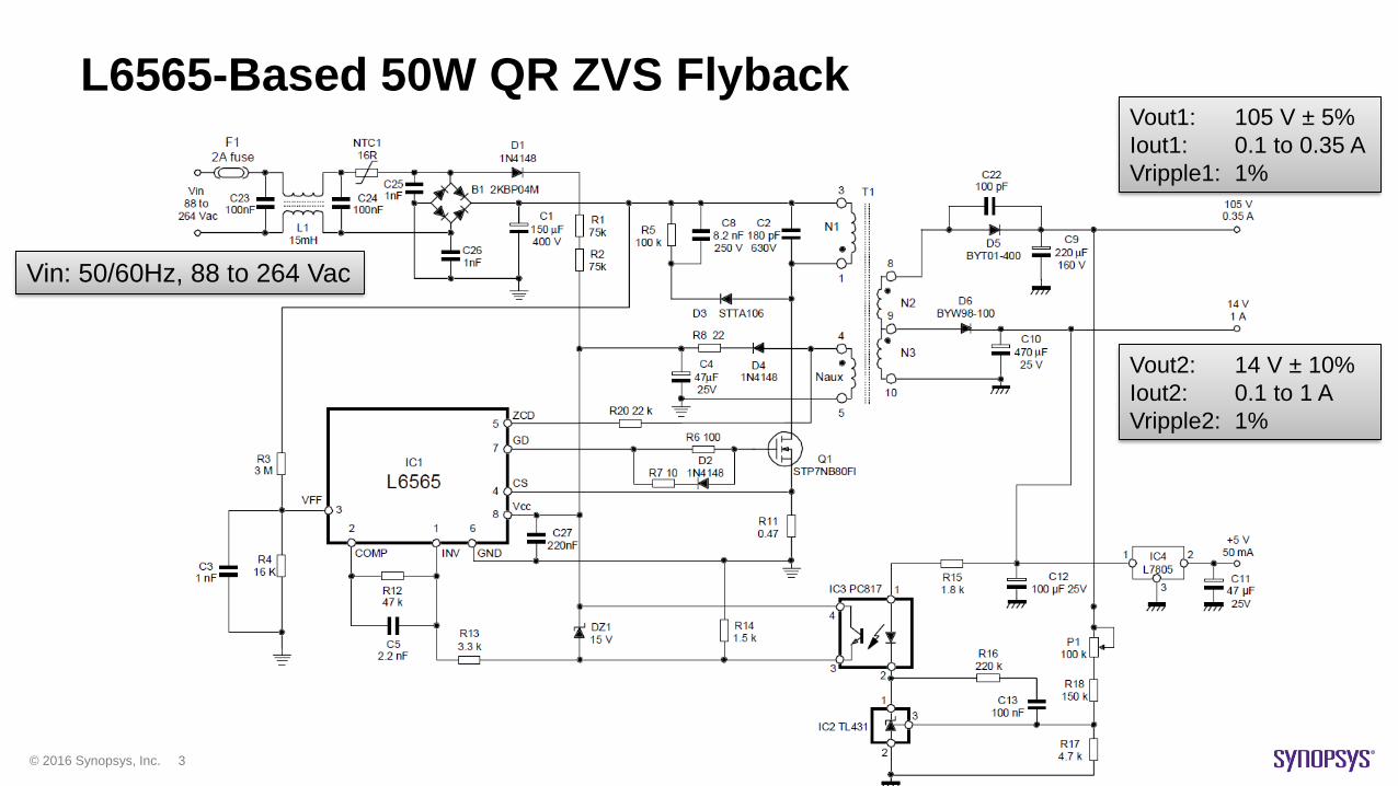
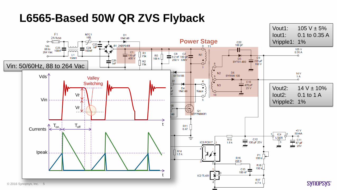
Vin: 50/60Hz, 88 to 264 Vac
Vout1: 105 V ± 5%
Iout1: 0.1 to 0.35 A
Vripple1: 1%
Vout2: 14 V ± 10%
Iout2: 0.1 to 1 A
Vripple2: 1%
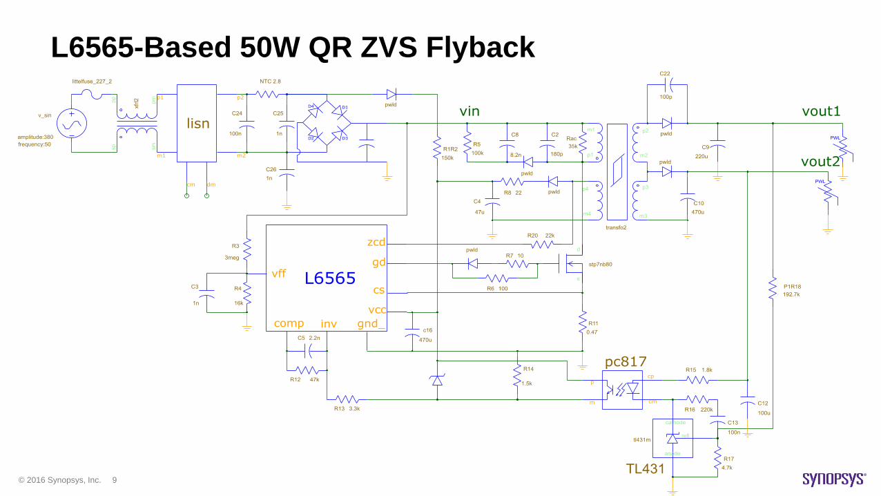
L6565-Based 50W QR ZVS Flyback
© 2016 Synopsys, Inc. 4
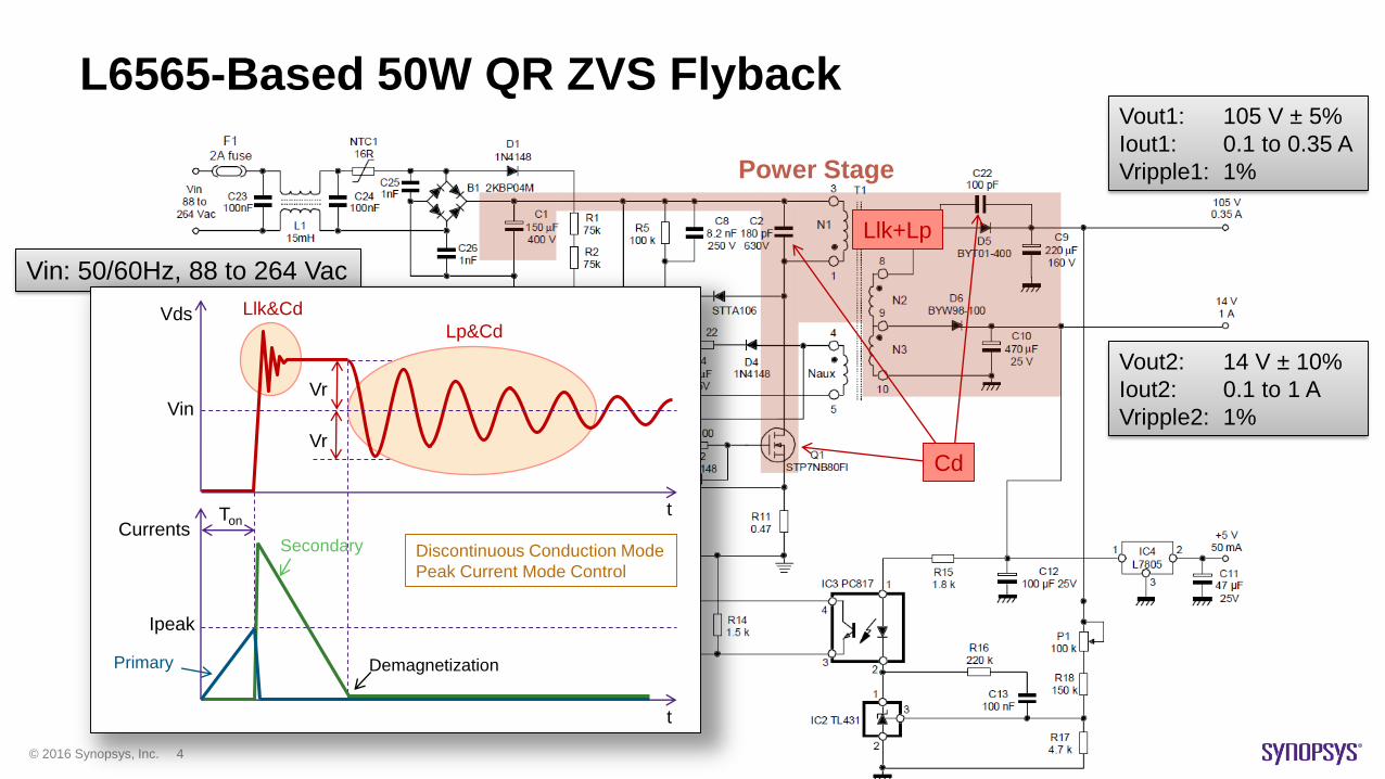
Vin: 50/60Hz, 88 to 264 Vac
L6565-Based 50W QR ZVS Flyback
Power Stage
Vds
tCurrents
t
Vr
Vr
Llk&Cd
Lp&Cd
Ipeak
Secondary
Vin
Primary Demagnetization
Ton
Llk+Lp
Cd
Llk+Lp
Vout1: 105 V ± 5%
Iout1: 0.1 to 0.35 A
Vripple1: 1%
Vout2: 14 V ± 10%
Iout2: 0.1 to 1 A
Vripple2: 1%
Discontinuous Conduction Mode
Peak Current Mode Control
© 2016 Synopsys, Inc. 5
Vin: 50/60Hz, 88 to 264 Vac
L6565-Based 50W QR ZVS Flyback
Power Stage
Vds
tCurrents
t
Ipeak
Vin
Ton Toff
Valley
Switching
Vout1: 105 V ± 5%
Iout1: 0.1 to 0.35 A
Vripple1: 1%
Vout2: 14 V ± 10%
Iout2: 0.1 to 1 A
Vripple2: 1%
Vr
Vr
© 2016 Synopsys, Inc. 6
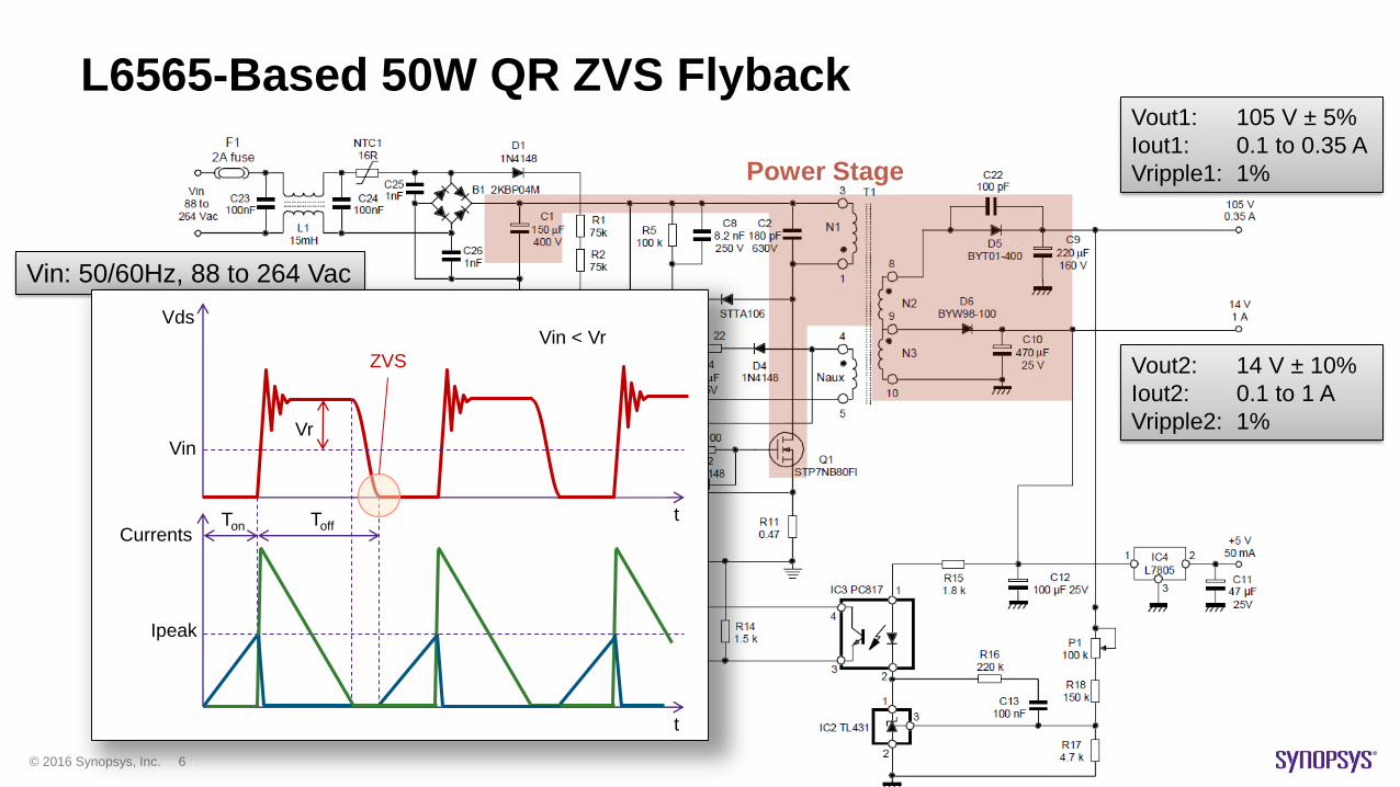
Vin: 50/60Hz, 88 to 264 Vac
L6565-Based 50W QR ZVS Flyback
Power Stage
Vds
tCurrents
t
Ipeak
Vin
Ton Toff
ZVS
Vr
Vin < Vr
Vout1: 105 V ± 5%
Iout1: 0.1 to 0.35 A
Vripple1: 1%
Vout2: 14 V ± 10%
Iout2: 0.1 to 1 A
Vripple2: 1%
© 2016 Synopsys, Inc. 7
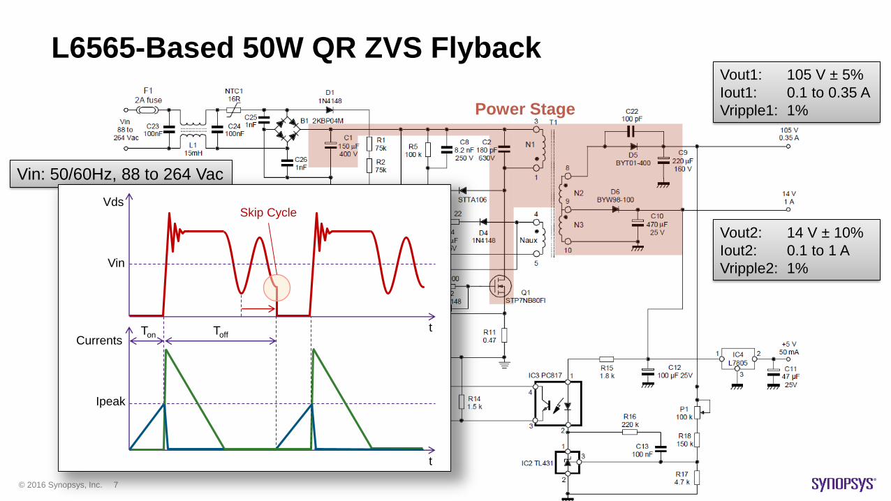
Vin: 50/60Hz, 88 to 264 Vac
L6565-Based 50W QR ZVS Flyback
Power Stage
Vds
tCurrents
t
Ipeak
Vin
Ton Toff
Skip Cycle
Vout1: 105 V ± 5%
Iout1: 0.1 to 0.35 A
Vripple1: 1%
Vout2: 14 V ± 10%
Iout2: 0.1 to 1 A
Vripple2: 1%
© 2016 Synopsys, Inc. 8
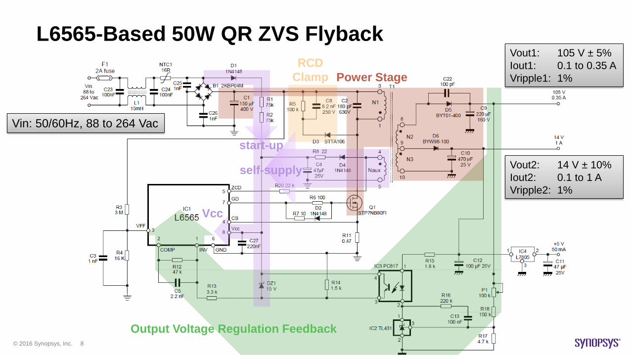
RCD
Clamp
Output Voltage Regulation Feedback
Vin: 50/60Hz, 88 to 264 Vac
Vout1: 105 V ± 5%
Iout1: 0.1 to 0.35 A
Vripple1: 1%
Vout2: 14 V ± 10%
Iout2: 0.1 to 1 A
Vripple2: 1%
L6565-Based 50W QR ZVS Flyback
Power Stage
Vcc
start-up
self-supply
© 2016 Synopsys, Inc. 9
L6565-Based 50W QR ZVS Flyback
© 2016 Synopsys, Inc. 10
Agenda
• Quasi-Resonant Flyback Converter (AN1326)
–Principles of Operation
–Simulation vs. Measurement
• Accurate Datasheet-Driven Modeling
–Controller Chip
–MOSFET
–Transformer
• Automated Verification
–EMI
– Loss / Efficiency

© 2016 Synopsys, Inc. 11
Current Sense and Primary Voltage
Full Load, Vin = 100 V
4µs 4µs
1V
100V

© 2016 Synopsys, Inc. 12
Current Sense and Primary Voltage
Full Load, Vin = 380 V
2µs 2µs
1V
100V
© 2016 Synopsys, Inc. 13
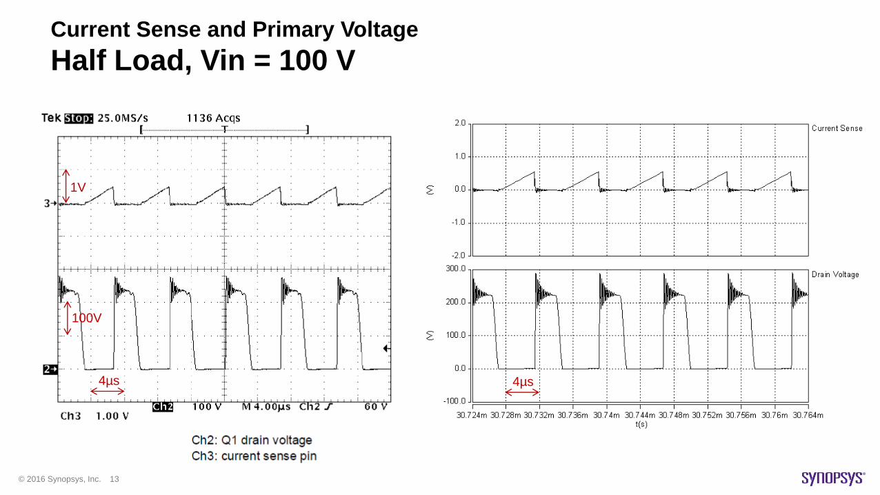
Current Sense and Primary Voltage
Half Load, Vin = 100 V
4µs 4µs
1V
100V
© 2016 Synopsys, Inc. 14
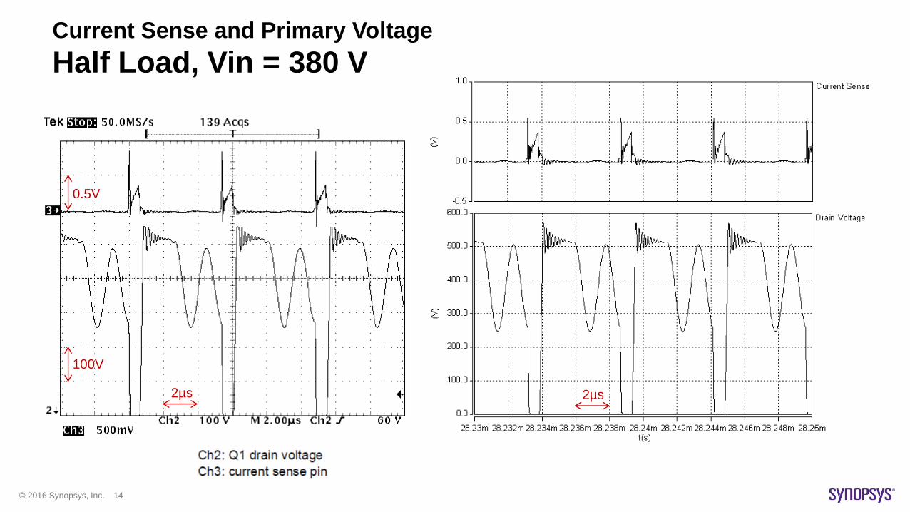
Current Sense and Primary Voltage
Half Load, Vin = 380 V
2µs 2µs
0.5V
100V
© 2016 Synopsys, Inc. 15
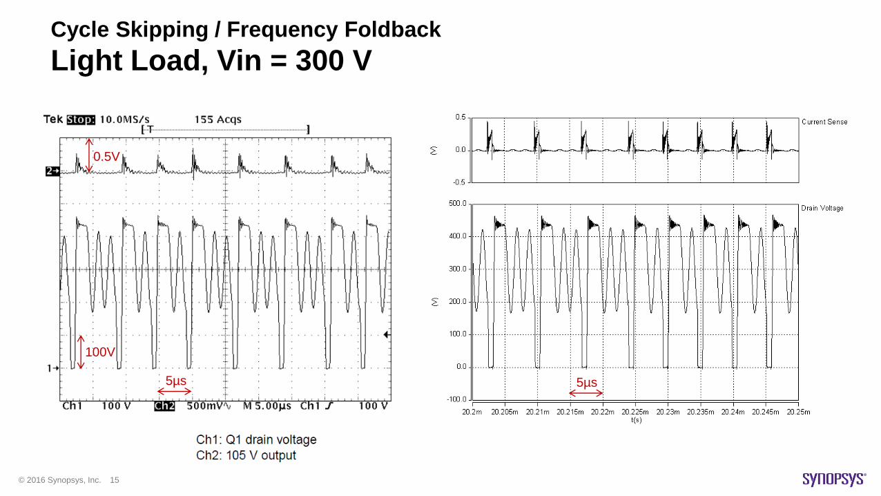
Cycle Skipping / Frequency Foldback
Light Load, Vin = 300 V
5µs 5µs
0.5V
100V
© 2016 Synopsys, Inc. 16
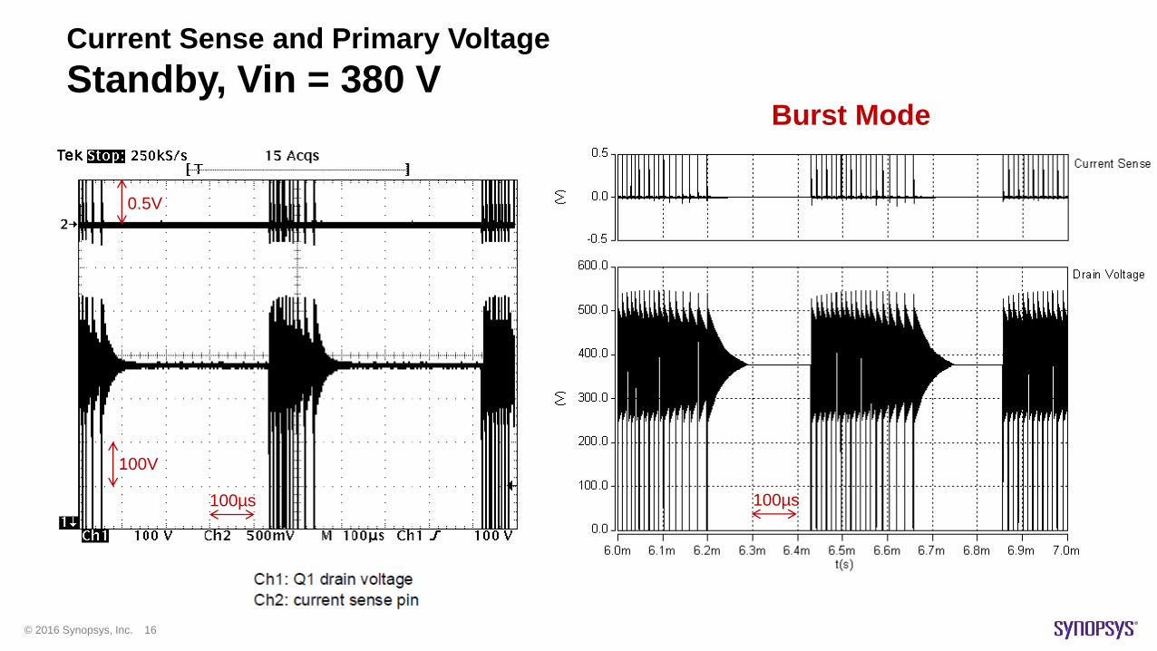
Current Sense and Primary Voltage
Standby, Vin = 380 VBurst Mode
100µs 100µs
0.5V
100V

© 2016 Synopsys, Inc. 17
Agenda
• Quasi-Resonant Flyback Converter (AN1326)
–Principles of Operation
–Simulation vs. Measurement
• Accurate Datasheet-Driven Modeling
–Controller Chip
–MOSFET
–Transformer
• Automated Verification
–EMI
– Loss / Efficiency
© 2016 Synopsys, Inc. 18
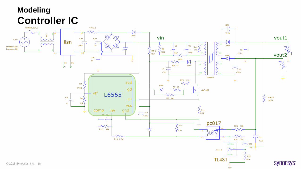
Modeling
Controller IC
© 2016 Synopsys, Inc. 19
Modeling
Controller IC
© 2016 Synopsys, Inc. 20
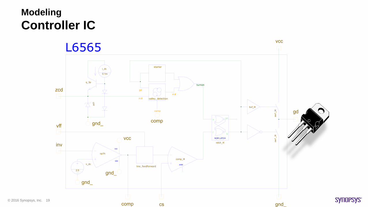
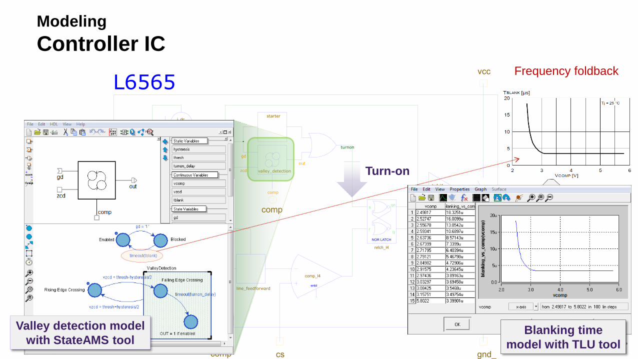
Modeling
Controller IC
Turn-on
Valley detection model
with StateAMS toolBlanking time
model with TLU tool
Frequency foldback
© 2016 Synopsys, Inc. 21
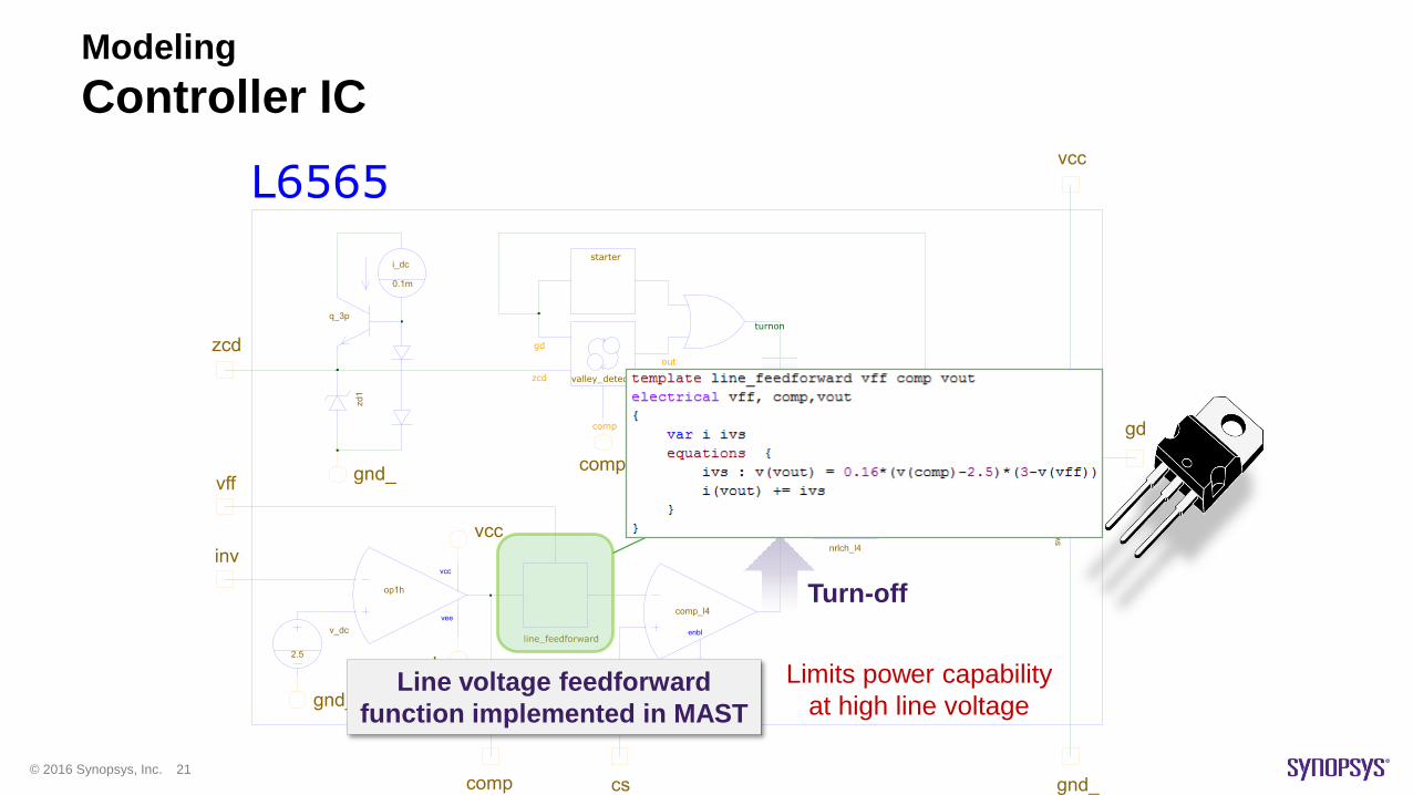
Modeling
Controller IC
Turn-on
Turn-off
Line voltage feedforward
function implemented in MAST
Limits power capability
at high line voltage
© 2016 Synopsys, Inc. 22
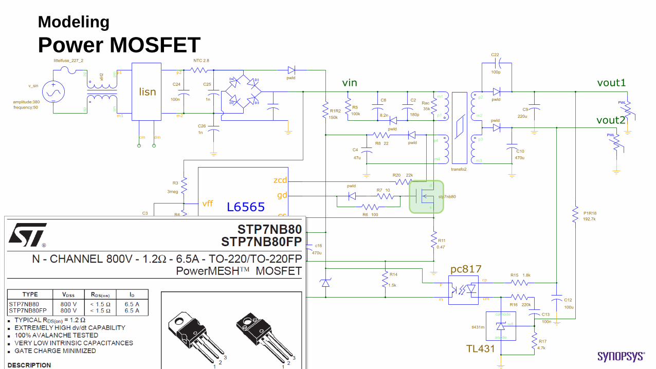
Modeling
Power MOSFET
© 2016 Synopsys, Inc. 23
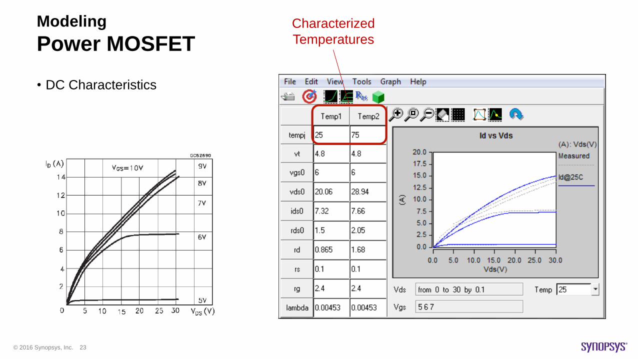
Modeling
Power MOSFET
• DC Characteristics
Characterized
Temperatures
© 2016 Synopsys, Inc. 24
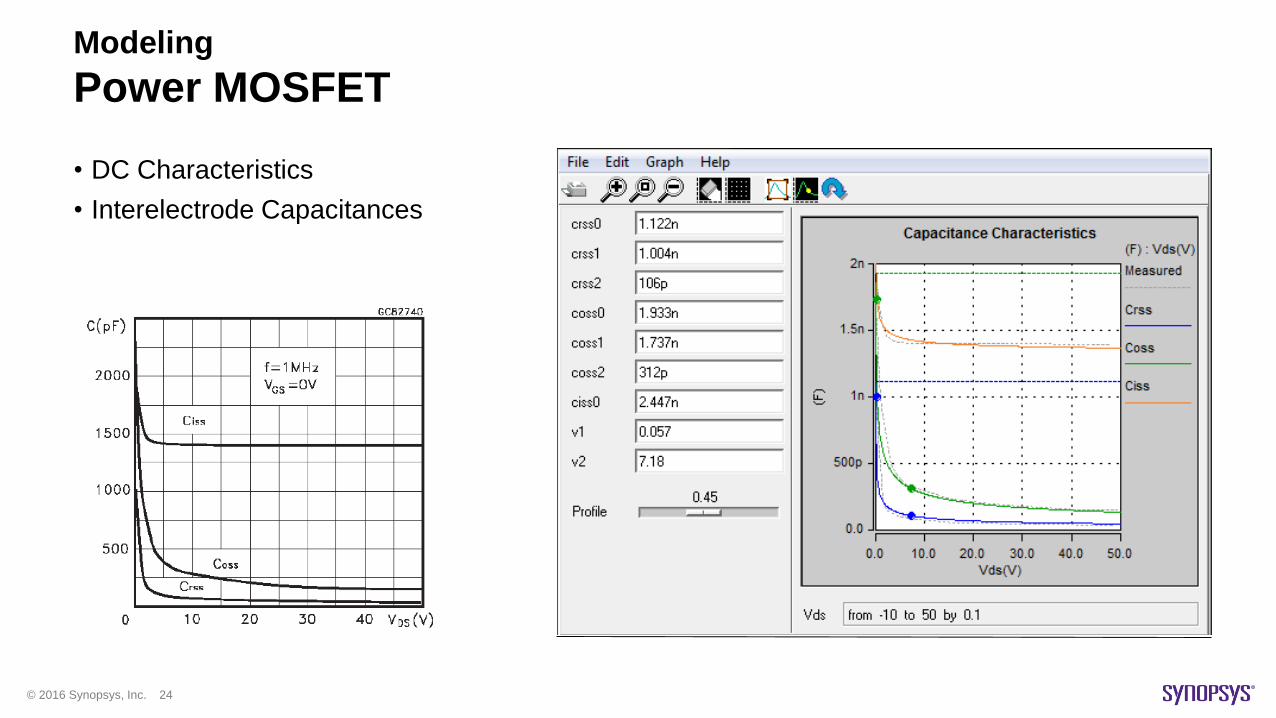
Modeling
Power MOSFET
• DC Characteristics
• Interelectrode Capacitances
© 2016 Synopsys, Inc. 25
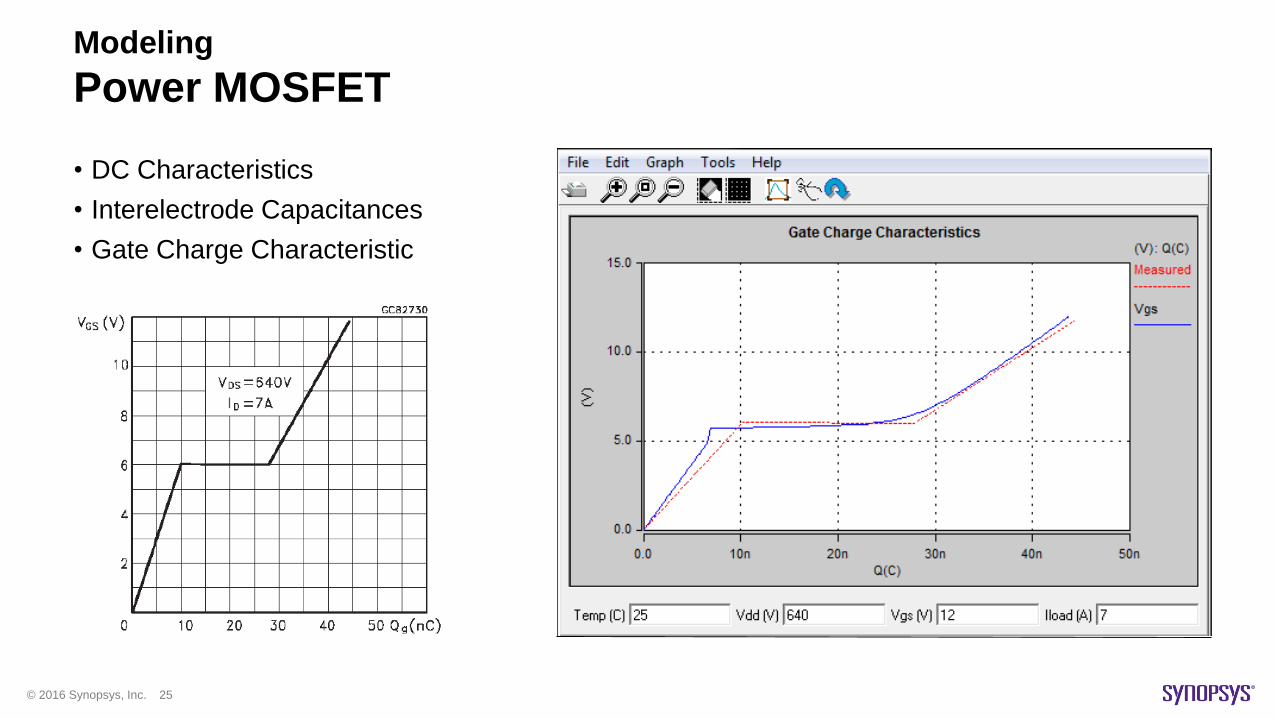
Modeling
Power MOSFET
• DC Characteristics
• Interelectrode Capacitances
• Gate Charge Characteristic
© 2016 Synopsys, Inc. 26
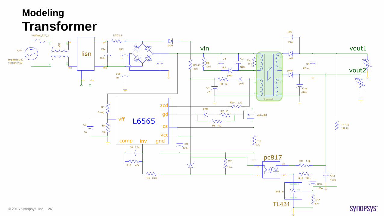
Modeling
Transformer

© 2016 Synopsys, Inc. 27
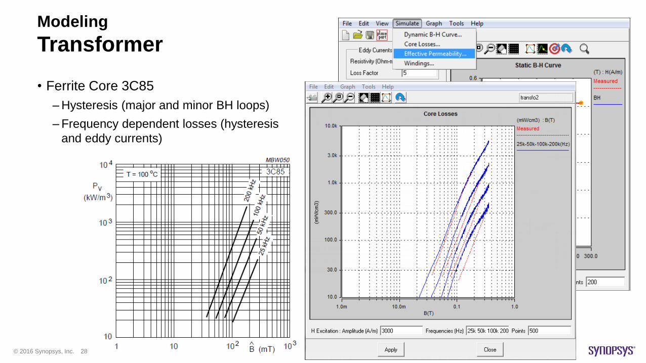
Modeling
Transformer
• Ferrite Core 3C85
–Hysteresis (major and minor BH loops)
–Frequency dependent losses (hysteresis
and eddy currents)
© 2016 Synopsys, Inc. 28
Modeling
Transformer
• Ferrite Core 3C85
–Hysteresis (major and minor BH loops)
–Frequency dependent losses (hysteresis
and eddy currents)
© 2016 Synopsys, Inc. 29
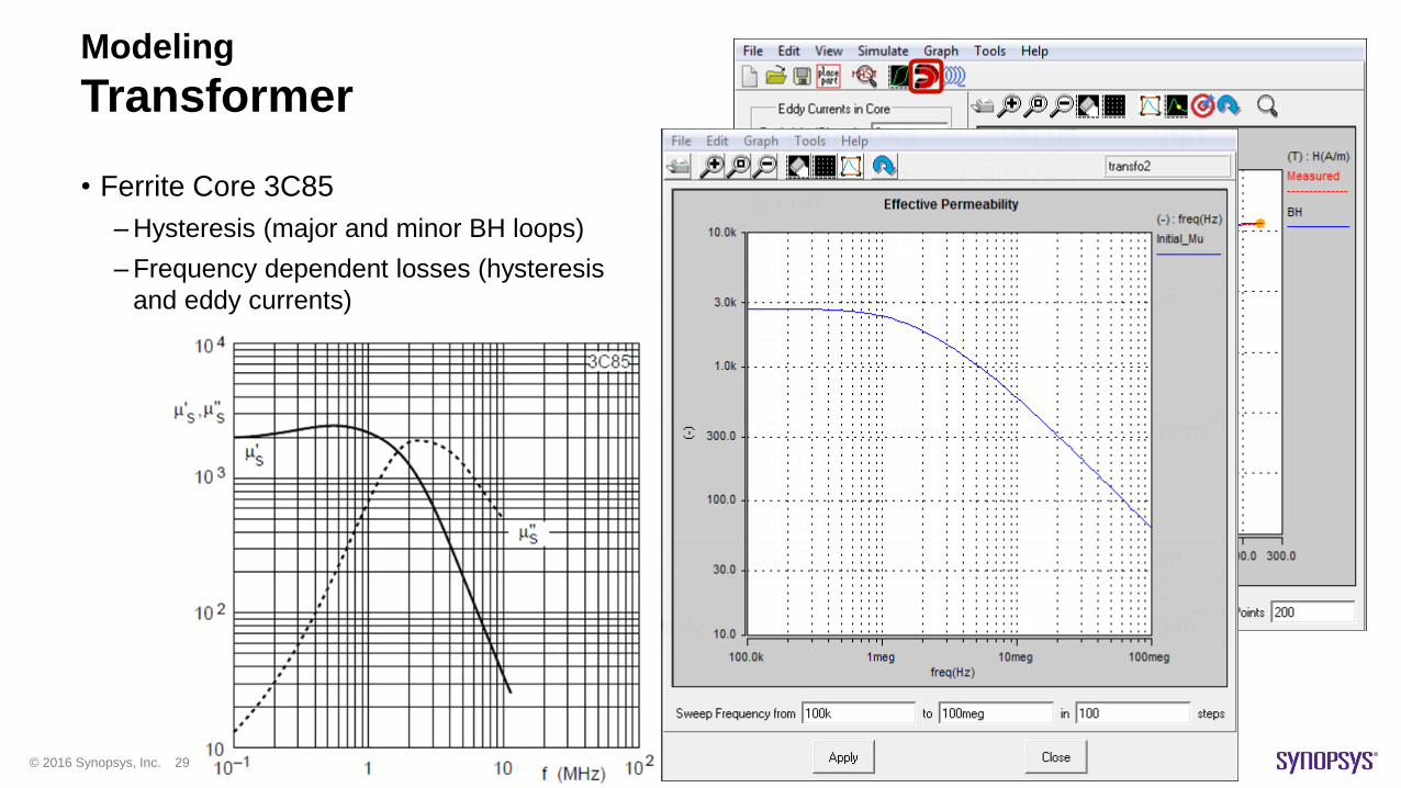
Modeling
Transformer
• Ferrite Core 3C85
–Hysteresis (major and minor BH loops)
–Frequency dependent losses (hysteresis
and eddy currents)
© 2016 Synopsys, Inc. 30
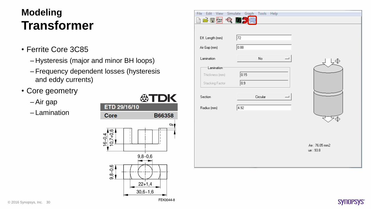
Modeling
Transformer
• Ferrite Core 3C85
–Hysteresis (major and minor BH loops)
–Frequency dependent losses (hysteresis
and eddy currents)
• Core geometry
–Air gap
– Lamination
© 2016 Synopsys, Inc. 31
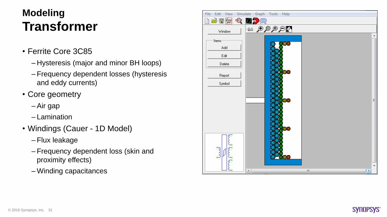
Modeling
Transformer
• Ferrite Core 3C85
–Hysteresis (major and minor BH loops)
–Frequency dependent losses (hysteresis
and eddy currents)
• Core geometry
–Air gap
– Lamination
• Windings (Cauer - 1D Model)
–Flux leakage
–Frequency dependent loss (skin and
proximity effects)
–Winding capacitances
© 2016 Synopsys, Inc. 32
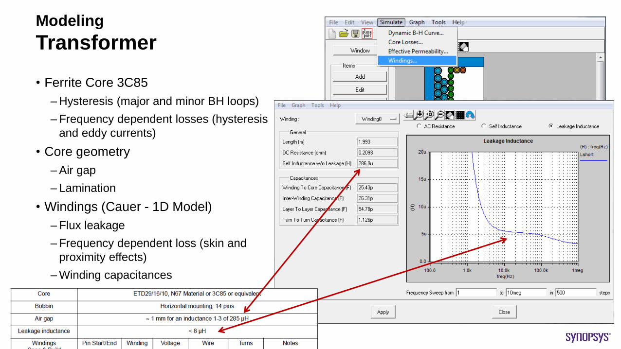
Modeling
Transformer
• Ferrite Core 3C85
–Hysteresis (major and minor BH loops)
–Frequency dependent losses (hysteresis
and eddy currents)
• Core geometry
–Air gap
– Lamination
• Windings (Cauer - 1D Model)
–Flux leakage
–Frequency dependent loss (skin and
proximity effects)
–Winding capacitances
© 2016 Synopsys, Inc. 33
Agenda
• Quasi-Resonant Flyback Converter (AN1326)
–Principles of Operation
–Simulation vs. Measurement
• Accurate Datasheet-Driven Modeling
–Controller Chip
–MOSFET
–Transformer
• Automated Verification
–EMI
– Loss / Efficiency
© 2016 Synopsys, Inc. 34
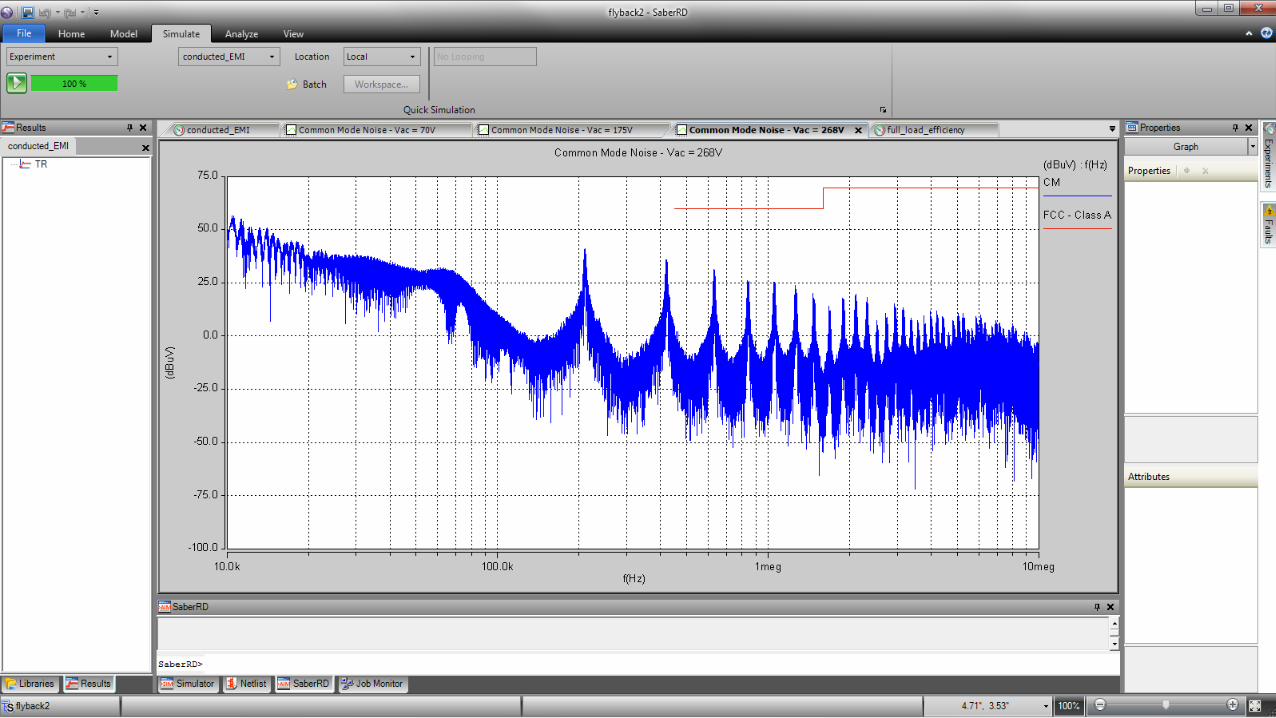
© 2016 Synopsys, Inc. 35
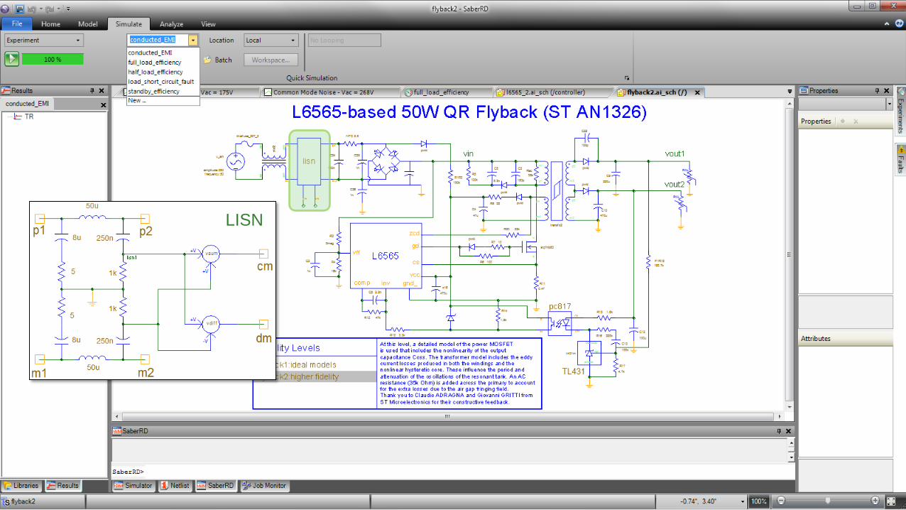
LISN
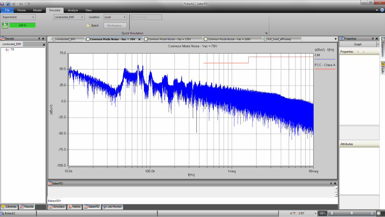
© 2016 Synopsys, Inc. 36
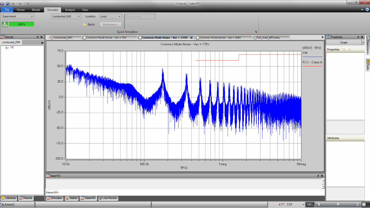
© 2016 Synopsys, Inc. 37
© 2016 Synopsys, Inc. 38
© 2016 Synopsys, Inc. 39
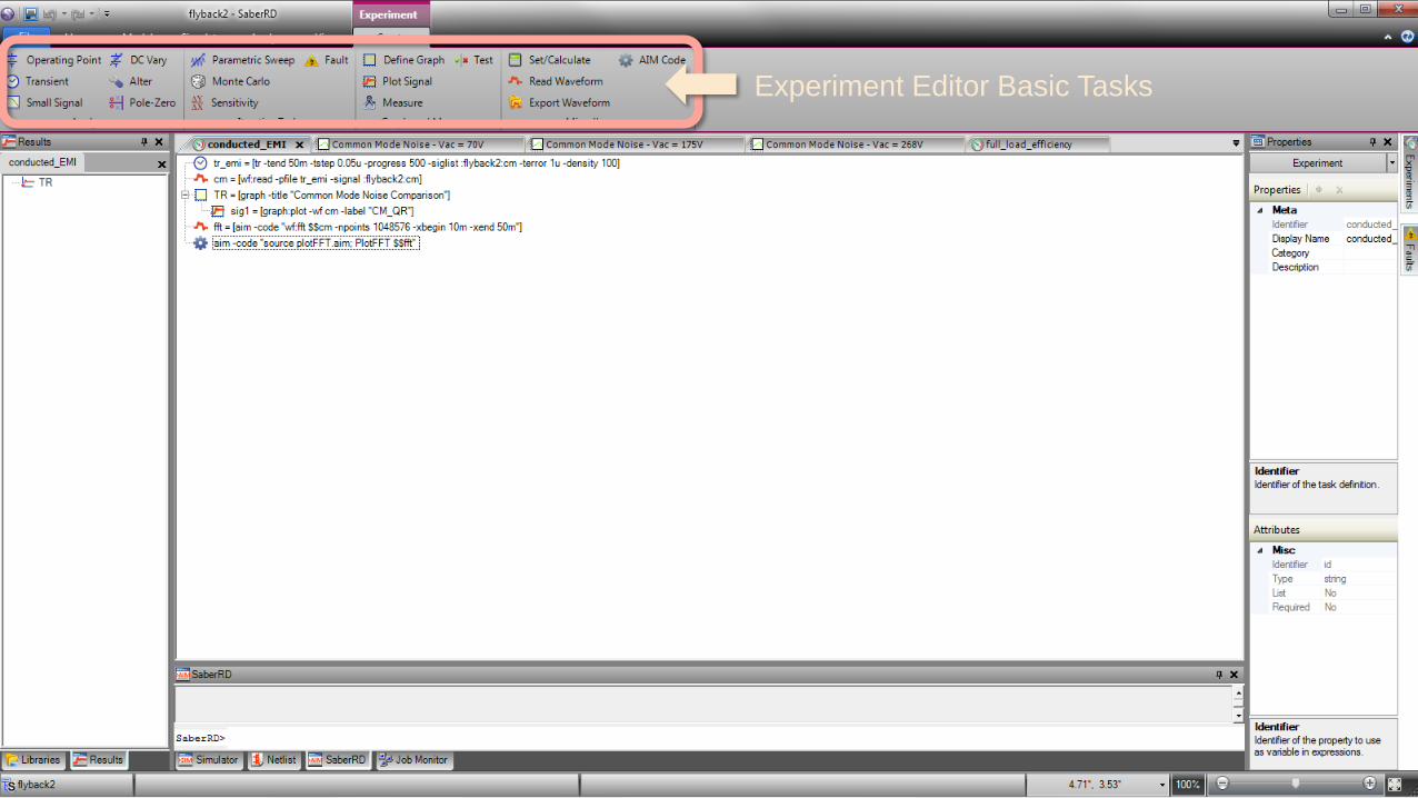
Experiment Editor Basic Tasks

© 2016 Synopsys, Inc. 40

© 2016 Synopsys, Inc. 41
Parallel
Computing
© 2016 Synopsys, Inc. 42

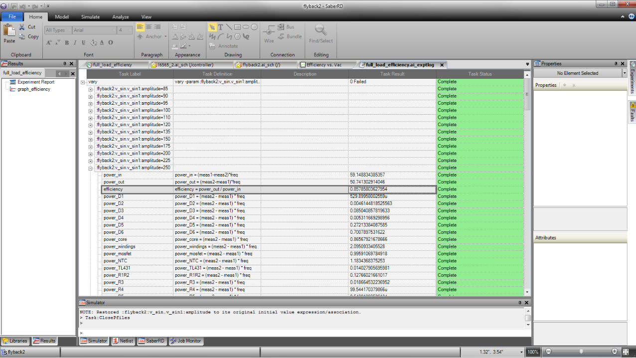
© 2016 Synopsys, Inc. 43
Most dissipative
components
© 2016 Synopsys, Inc. 44
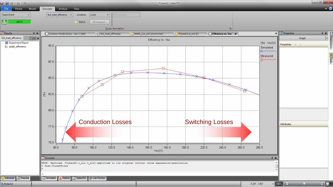
Conduction Losses Switching Losses
© 2016 Synopsys, Inc. 45
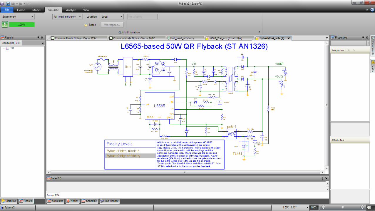
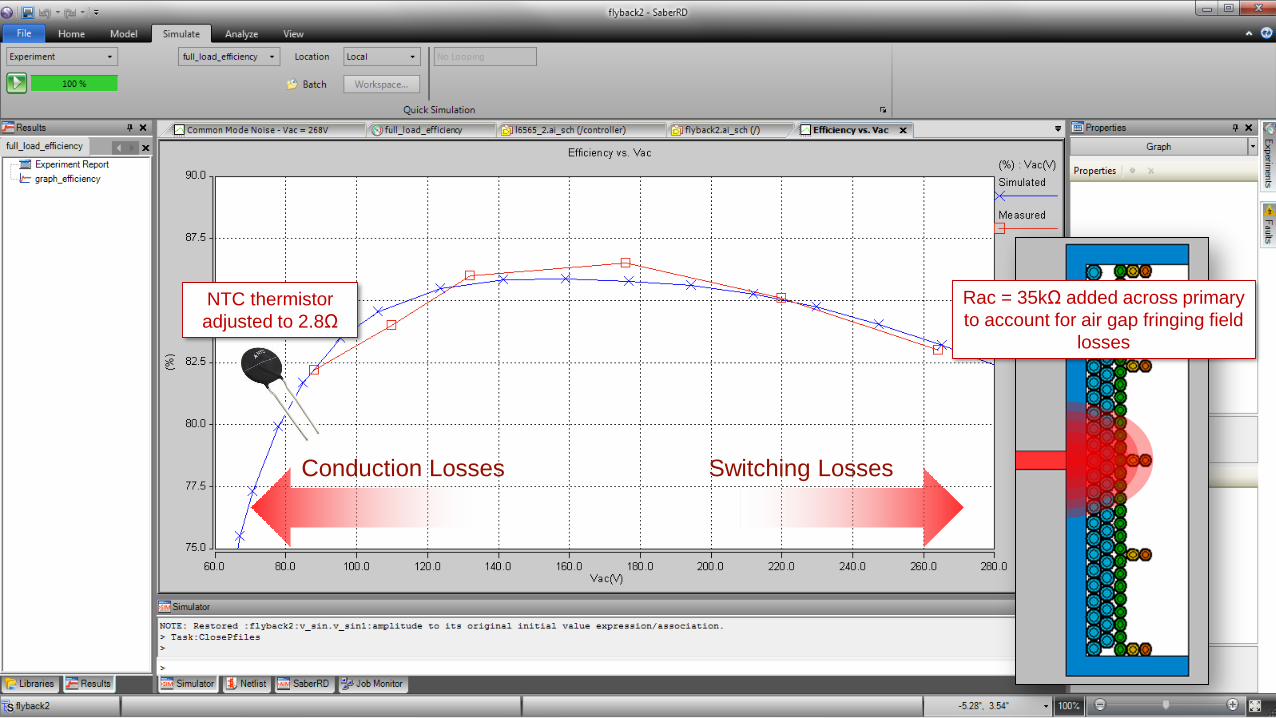
Conduction Losses Switching Losses
Rac = 35kΩ added across primary
to account for air gap fringing field
losses
NTC thermistor
adjusted to 2.8Ω
© 2016 Synopsys, Inc. 46
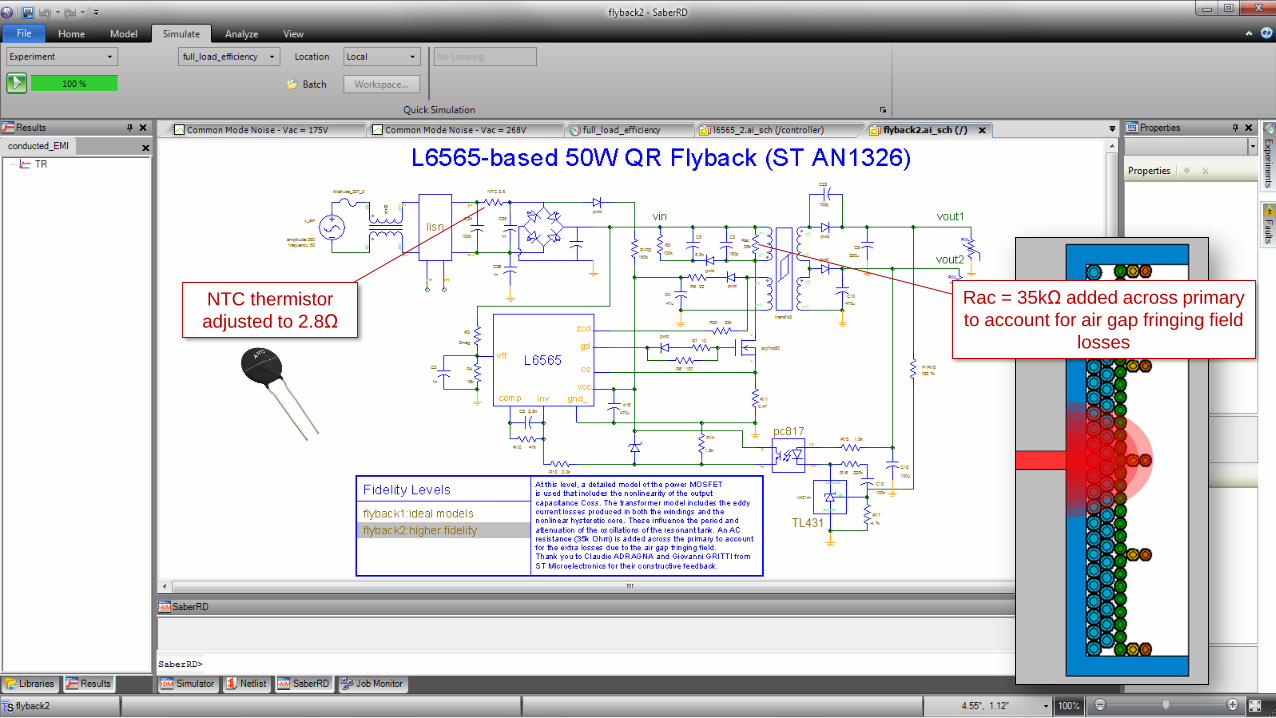
NTC thermistor
adjusted to 2.8Ω
Rac = 35kΩ added across primary
to account for air gap fringing field
losses
© 2016 Synopsys, Inc. 47
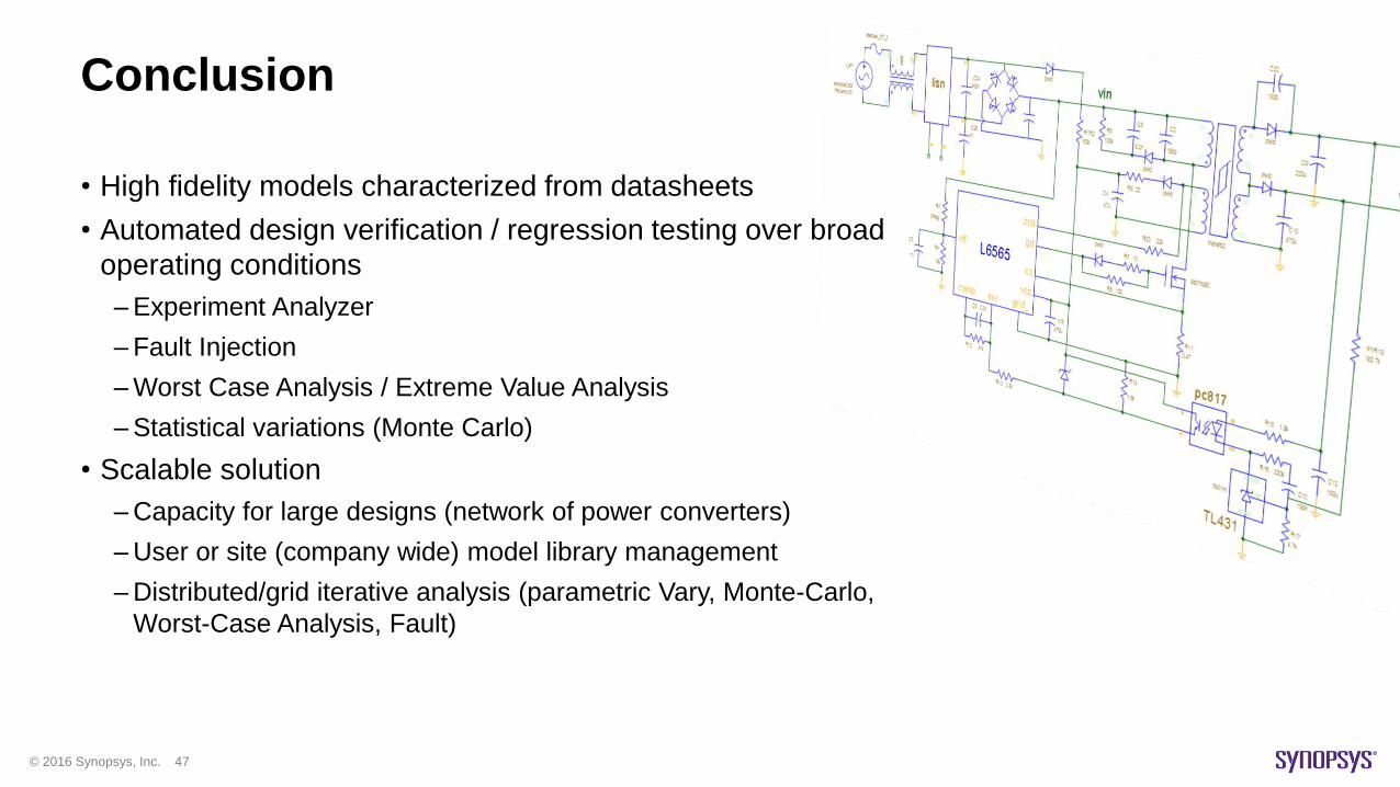
Conclusion
• High fidelity models characterized from datasheets
• Automated design verification / regression testing over broad
operating conditions
–Experiment Analyzer
–Fault Injection
–Worst Case Analysis / Extreme Value Analysis
–Statistical variations (Monte Carlo)
• Scalable solution
–Capacity for large designs (network of power converters)
–User or site (company wide) model library management
–Distributed/grid iterative analysis (parametric Vary, Monte-Carlo,
Worst-Case Analysis, Fault)
© 2016 Synopsys, Inc. 48
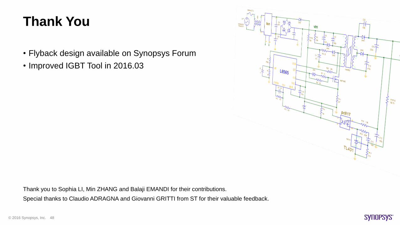
Thank You
• Flyback design available on Synopsys Forum
• Improved IGBT Tool in 2016.03
Thank you to Sophia LI, Min ZHANG and Balaji EMANDI for their contributions.
Special thanks to Claudio ADRAGNA and Giovanni GRITTI from ST for their valuable feedback.


