Page 1
SAE Aero Design
Concept Generation and Selection
Ali Alqalaf, Jasem Alshammari, Dong Yang Cao,
Darren Frankenberger, Steven Goettl, and John Santoro
Team 16
Submitted towards partial fulfillment of the requirements for Mechanical Engineering Design I – Fall 2015
Department of Mechanical Engineering
Northern Arizona University Flagstaff, AZ 86011
Page 2
Table of Contents
1.) Introduction……………………………………………………………....……....... 2
2.) Functional Diagram….…………………………………………………………….. 23
3.) Relative Weights of Criteria…………………………………………....………….. 3
4.) Concept Generation……………………………………………………………….. 420
5.) Updated Project Plan…….……………………………………………………….... 2122
6.) Conclusions……………………………………………………………………….... 22
7.) References………………………………………………………………………….. 23
1
Page 3
1. Introduction
The SAE Aero Design Capstone team has conducted research on the problem definition
and project plan, and now moves onto concept generation and selection. The team began with
recognizing which functionalities of the aircraft needed concepts to be developed and chosen.
After these were recognized, criteria for each functionality were determined, then weighted
based on importance. Multiple concepts were then developed for each functionality. These were
compiled into decision matrices and then scored. These designs are not necessarily final, but a
good idea of what the team wants to accomplish with the design of the aircraft.
2. Functional Diagram
Figure 1. Functional Diagram
Shown above is the functional diagram for the electrical components of the aircraft. Red
wires are positive, and black wires are negative. Blue wires denote servo wires. The battery is
connected to the electronic speed control (ESC), which is then connected to the motor with a
variable controller allowing for different power settings. The arming plug is connected to the
battery as well, providing a killswitch. This is required by competition rules. Also wired to the
battery is the battery eliminator circuit (BEC). Connected to the BEC is the receiver via a servo
wire. This eliminates the need for a separate battery for the receiver. Configured to the receiver
2
Page 4
are the servos connected to the different control surfaces. The rudder servo and nose gear servo
are connected via a yharness, and one will be reversed giving the proper control to the user.
There will be one elevator servo and two aileron servos connected to the receiver as well via a
yharness. Finally, the receiver is configured to the transmitter wirelessly via a 2.4 Ghz signal.
3. Relative Weights of Criteria
Table 1. Relative Weights of Criteria Landing Gear
Criteria Weight Strength Coefficient of Drag
Control Raw Total
Normalized Weights
Weight 0 1 0 1 0.167
Strength 1 0 0 1 0.167
Coefficient of Drag
0 1 0 1 0.167
Control 1 1 1 3 0.5
Illustrated above is one example of the relative weights of criteria, specifically for the
landing gear decision matrix. The criteria are compared to each other, and ranked based on
importance. Score are given as: 1 point if deemed more important, 0 points if deemed less
important. For example, weight in the left hand column was considered less important that
strength, more important than coefficient of drag and less important than control. Weight,
strength, and coefficient of drag each scored one point, meaning they were considered more
important that at least one other criteria. Control scored 3 points as it was deemed the most
important criteria in regards to the landing gear.
3
Page 5
4. Concept Generation
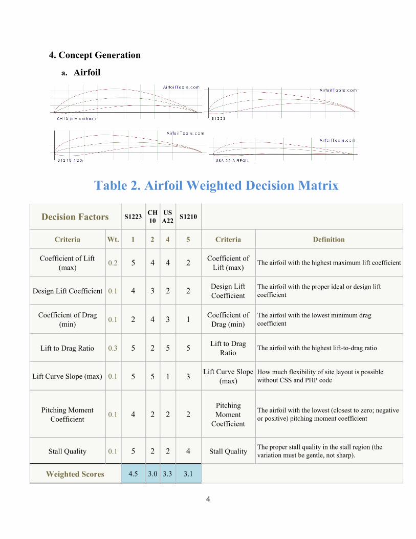
a. Airfoil
Table 2. Airfoil Weighted Decision Matrix
Decision Factors S1223 CH10 USA22 S1210
Criteria Wt. 1 2 4 5 Criteria Definition
Coefficient of Lift (max) 0.2 5 4 4 2 Coefficient of
Lift (max) The airfoil with the highest maximum lift coefficient
Design Lift Coefficient 0.1 4 3 2 2 Design Lift Coefficient
The airfoil with the proper ideal or design lift coefficient
Coefficient of Drag (min) 0.1 2 4 3 1 Coefficient of
Drag (min) The airfoil with the lowest minimum drag coefficient
Lift to Drag Ratio 0.3 5 2 5 5 Lift to Drag Ratio
The airfoil with the highest lifttodrag ratio
Lift Curve Slope (max) 0.1 5 5 1 3 Lift Curve Slope (max)
How much flexibility of site layout is possible without CSS and PHP code
Pitching Moment Coefficient 0.1 4 2 2 2
Pitching Moment Coefficient
The airfoil with the lowest (closest to zero; negative or positive) pitching moment coefficient
Stall Quality 0.1 5 2 2 4 Stall Quality The proper stall quality in the stall region (the variation must be gentle, not sharp).
Weighted Scores 4.5 3.0 3.3 3.1
4
Page 6
The decision matrix above shows the values that we gave each of the design for
the criteria the team determined was most important.The team determined that the lift to
drag ratio was most important with the maximum coefficient of lift coming in a close
second. This was determined because the airfoil with best lift to drag ratio will be most
effective for carrying a payload. The highest coefficient of lift combined with the highest
lift to drag ratio will give us the best performing airfoil design. The airfoil that we chose
based on the criteria was the S1223 airfoil.
5
Page 7
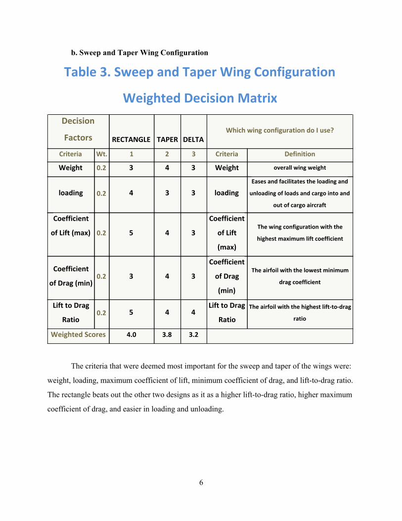
b. Sweep and Taper Wing Configuration
Table 3. Sweep and Taper Wing Configuration
Weighted Decision Matrix
Decision
Factors RECTANGLE TAPER DELTA
Which wing configuration do I use?
Criteria Wt. 1 2 3 Criteria Definition
Weight 0.2 3 4 3 Weight overall wing weight
loading 0.2 4 3 3 loading
Eases and facilitates the loading and
unloading of loads and cargo into and
out of cargo aircraft
Coefficient
of Lift (max) 0.2 5 4 3
Coefficient
of Lift
(max)
The wing configuration with the
highest maximum lift coefficient
Coefficient
of Drag (min) 0.2 3 4 3
Coefficient
of Drag
(min)
The airfoil with the lowest minimum
drag coefficient
Lift to Drag
Ratio 0.2 5 4 4
Lift to Drag
Ratio
The airfoil with the highest lift-to-drag
ratio
Weighted Scores 4.0 3.8 3.2
The criteria that were deemed most important for the sweep and taper of the wings were:
weight, loading, maximum coefficient of lift, minimum coefficient of drag, and lifttodrag ratio.
The rectangle beats out the other two designs as it as a higher lifttodrag ratio, higher maximum
coefficient of drag, and easier in loading and unloading.
6
Page 8
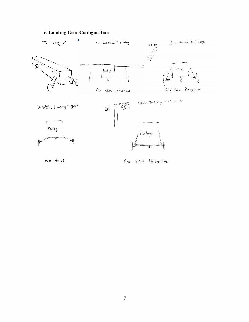
c. Landing Gear Configuration
7
Page 9
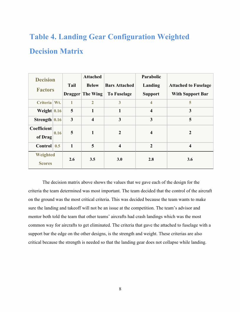
Table 4. Landing Gear Configuration Weighted
Decision Matrix
Decision
Factors Tail
Dragger
Attached
Below
The Wing
Bars Attached
To Fuselage
Parabolic
Landing
Support
Attached to Fuselage
With Support Bar
Criteria Wt. 1 2 3 4 5
Weight 0.16 5 1 1 4 3
Strength 0.16 3 4 3 3 5
Coefficient
of Drag 0.16 5 1 2 4 2
Control 0.5 1 5 4 2 4
Weighted
Scores 2.6 3.5 3.0 2.8 3.6
The decision matrix above shows the values that we gave each of the design for the
criteria the team determined was most important. The team decided that the control of the aircraft
on the ground was the most critical criteria. This was decided because the team wants to make
sure the landing and takeoff will not be an issue at the competition. The team’s advisor and
mentor both told the team that other teams’ aircrafts had crash landings which was the most
common way for aircrafts to get eliminated. The criteria that gave the attached to fuselage with a
support bar the edge on the other designs, is the strength and weight. These criterias are also
critical because the strength is needed so that the landing gear does not collapse while landing.
8
Page 10
d. Fuselage Design
(From left to right Rectangular Prism, Cylindrical, Bar Design and Triangular Prism)
Table 5. Fuselage Design Weighted Decision Matrix
Decision Factors Rectangular Prism Cylindrical Bar
Design Triangular Prism
Criteria Wt. 1 2 3 4 Criteria Definition
Weight 0.3 5 5 2 5 Weight Overall weight that the fuselage adds to the plane
Strength 0.3 4 2 3 5 Strength How much force the fuselage design can have exerting on it
before it breaks
Coefficient of Drag 0.3 4 5 2 3 Coefficie
nt of Drag The fuselage with the lowest minimum drag coefficient
Length 0.1 5 4 3 4 Length The shortest fuselage the plane can have
Weighted Scores 4.4 4.0 2.4 4.3
The fuselage is another critical design because it must keep drag to a minimum with also
be strong with the least amount of weight and length. The less length the fuselage has, the more
9
Page 11
width we can give the wing which creates more lift. The strength, weight and coefficient of drag
are weighted more because those criteria will affect the flight of the aircraft more than the length
of the fuselage. The team decided that the length of the rectangular prism would be easier to
minimize than the triangular prism design, while keeping the strength of the fuselage as well.
The team also decided that the aircraft could get more volume with a rectangular prism which
makes loading and unloading the payload bay much easier. The coefficient of drag was also less
because the team believed the rectangular prism would have a more continuous airflow over the
fuselage when it joins with the horizontal and vertical stabilizers.
e. Vertical and Horizontal Stabilizers
Conventional Tail Ttail Dual Tail Triple Tail Twin Tail
10
Page 12
Table 6. Vertical and Horizontal Stabilizers Decision
Matrix
Decision
Factors Conventional
Tail T-tail
Dual
Tail
Triple
Tail
Twin
Tail
Criteria Wt. 1 2 3 4 5 Criteria Definition
Stability
Coefficient 0.30 4 3 3 3 4
Stability
Coefficient
The higher the stability coefficient, the
straighter the airplane will move
pitching control
(up and down) 0.25 4 4 3 2 4
pitching
control (up
and down)
The horizontal stabilizer prevent up
and down motion of the nose of the
airplane
yaw control
(right and left) 0.25 4 4 3 3 5
yaw control
(right and left)
The vertical stabilizer prevent the
airplane from swinging side to side
Weight 0.20 4 4 3 2 3 Weight The weight of the tail
Weight Scores 4.0 3.7 3.0 2.6 4.1
The decision matrix above shows the design scores for vertical and horizontal stabilizers. The
stabilizers job is to pitch (up and down) and yaw (right and left) the airplane. The twin tail design wins
because it is more stable than most of the other tails. Furthermore, having two vertical stabilizers will help
in being more effective upon other tails in yawing. Also, the height is cut in half if one was to use just one
vertical stabilizer.
f. Wing Placement Configuration
11
Page 13
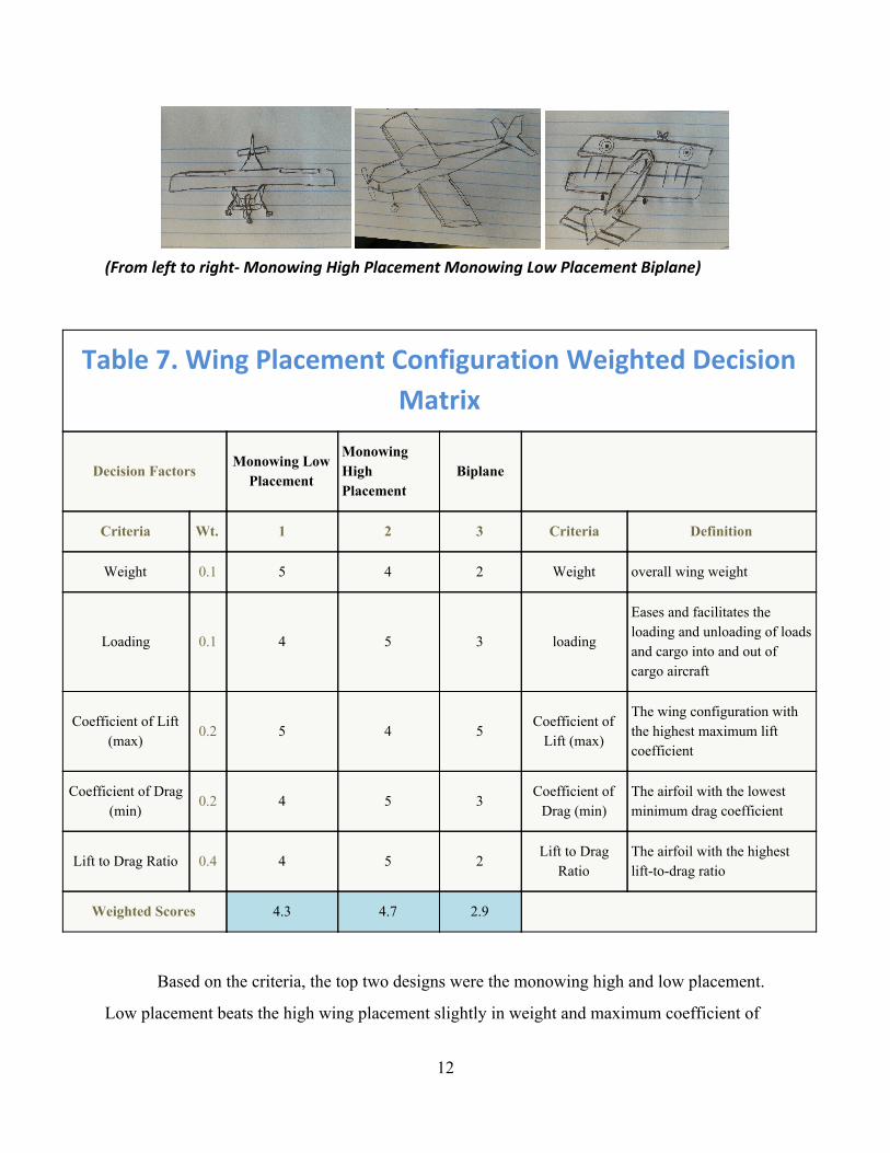
(From left to right- Monowing High Placement Monowing Low Placement Biplane)
Table 7. Wing Placement Configuration Weighted Decision
Matrix
Decision Factors Monowing Low Placement
Monowing High Placement
Biplane
Criteria Wt. 1 2 3 Criteria Definition
Weight 0.1 5 4 2 Weight overall wing weight
Loading 0.1 4 5 3 loading
Eases and facilitates the loading and unloading of loads and cargo into and out of cargo aircraft
Coefficient of Lift (max)
0.2 5 4 5 Coefficient of Lift (max)
The wing configuration with the highest maximum lift coefficient
Coefficient of Drag (min)
0.2 4 5 3 Coefficient of Drag (min)
The airfoil with the lowest minimum drag coefficient
Lift to Drag Ratio 0.4 4 5 2 Lift to Drag
Ratio The airfoil with the highest lifttodrag ratio
Weighted Scores 4.3 4.7 2.9
Based on the criteria, the top two designs were the monowing high and low placement.
Low placement beats the high wing placement slightly in weight and maximum coefficient of
12
Page 14
lift. The high placement design beats out the low placement design, because it offers a smaller
coefficient of drag, higher lifttodrag ratio, and ease of loading.
g. Payload Configuration
Table 8. Payload Configuration Weighted Decision Matrix
Decision Factors
Box
w/
Hing
ed
Lid
Spring
Loaded
Plates
Removable
Center Seam
Box
Box w/
Sliding Lid
Criteria Wt. 1 2 3 4 Criteria Definition
Payload (max) 0.15 3 3 3 3 Payload
(max) Overall payload weight
Weight 0.40 3 2 1 4 Weight Total weight of configuration
Cost 0.30 2 1 3 2 Cost Cost of payload configuration
13
Page 15
material
Ease of Construction 0.15 4 1 3 4 Ease of
Construction Time required to construct
Weighted Scores 2.9 1.7 2.2 3.3
Shown above are the payload configuration design concepts. Also above, is the decision
matrix for the payload configuration. The payload configuration holds the payload in place in the
fuselage. In terms of criteria, weight was deemed the most important, followed by cost, and
payload and ease of construction. Design option 1 and design option 4 were the two highest
ranking designs. Design option 4, the box with the sliding lid as it slightly edged option 1 in
regards to weight and cost.
h. Material Comparison
Design 1: Plastic http://www.aliexpress.com Design 2: Wood https://commons.wikimedia.org
Design 3: foam http://forums.sjgames.com Design 4: Aluminum http://www.omnisteelsupply.com
14
Page 16
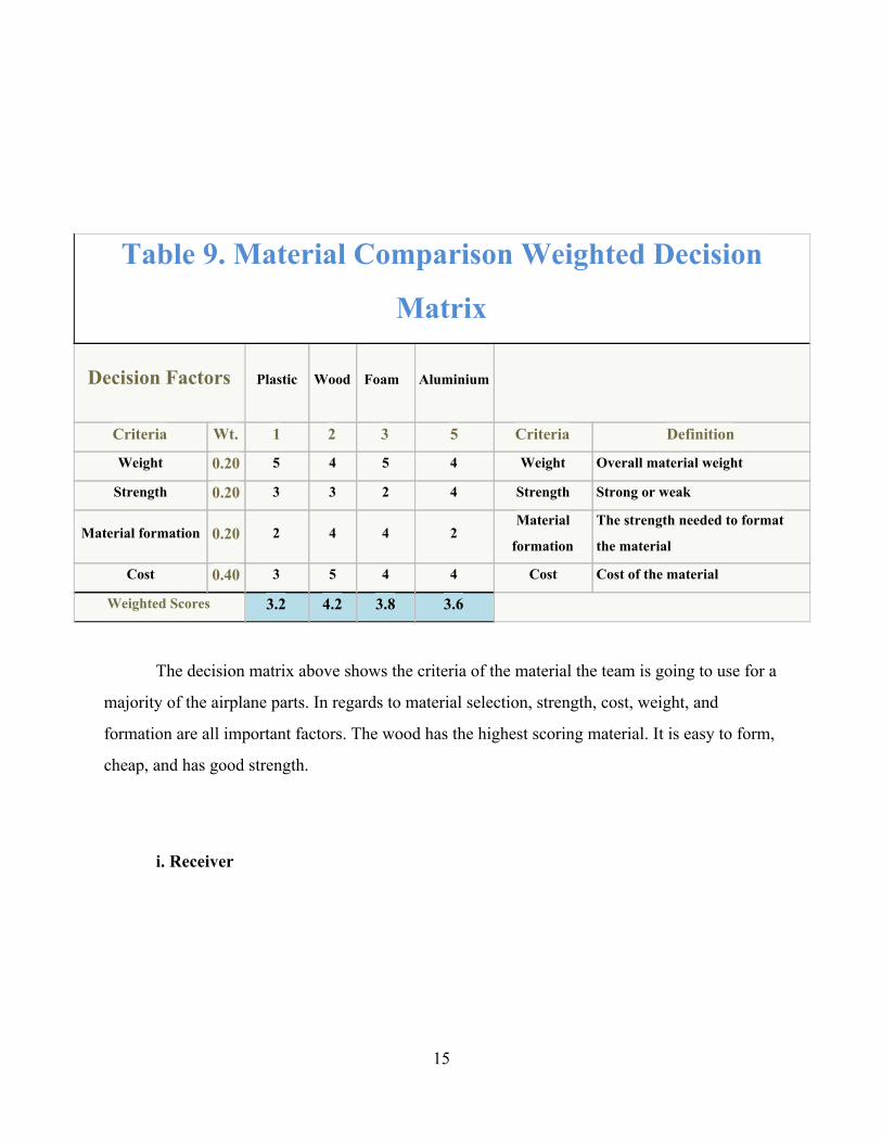
Table 9. Material Comparison Weighted Decision
Matrix
Decision Factors Plastic Wood
Foam
Aluminium
Criteria Wt. 1 2 3 5 Criteria Definition
Weight 0.20 5 4 5 4 Weight Overall material weight
Strength 0.20 3 3 2 4 Strength Strong or weak
Material formation 0.20 2 4 4 2 Material
formation
The strength needed to format
the material
Cost 0.40 3 5 4 4 Cost Cost of the material
Weighted Scores 3.2 4.2 3.8 3.6
The decision matrix above shows the criteria of the material the team is going to use for a
majority of the airplane parts. In regards to material selection, strength, cost, weight, and
formation are all important factors. The wood has the highest scoring material. It is easy to form,
cheap, and has good strength.
i. Receiver
15
Page 17
design 1, 2, 3: www.spektrumrc.com
Table 10. Receiver Weighted Decision Matrix
Decision Factors
4 Channel
Aircraft
Receiver
6 Channel
Aircraft
Receiver
7 Channel
Aircraft
Receiver
Criteria Wt. 1 2 3 Criteria Definition
weight 0.3 5 5 0 weight
The receiver with the
minimum weight
loading 0.2 3 3 2 loading
The receiver with minimum
loading
time period recorded 0.2 5 5 5
time period
recorded
The receiver with the suitable
time period recorded
altitude recorded 0.2 4 5 4
altitude
recorded
The receiver with the expected
altitude recorded
Quality 0.1 5 4 5 Quality
The receiver should be with
the best quality
Weighted Scores 4.2 4.3 2.5
The decision matrix above shows the design scores of the receiver selection. The team
decided that the most important criteria is the weight of the receiver, with loading time period
recorded, altitude recorded and quality following. Based on these criteria and the scorings, the
team will use a 6 channel aircraft receiver.
j. Transmitter
16
Page 18
design 4, 5, 6: www.spektrumrc.com
Table 11. Transmitter Configuration Weighted
Decision Matrix
Decision Factors
5 channel
Transmitter
6 channel
transmitter
7 channel
transmitter Which transmitter do I use?
Criteria Wt. 1 2 4 Criteria Definition
Weight 0.2 4 1 5 Weight overall transmitter weight
loading 0.3 2 0 0 loading
transmitter loading should be as
small as possible
attenuate transmit
signal 0.2 5 3 3
attenuate
transmit
signal
the transmitter should transmit
suitable signal to the radio station
gains 0.1 5 5 5 gains the ability of gaining signals
losses 0.2 3 4 1 losses the ability of losses signals
Weighted Scores 3.5 2.1 2.3
This is our team transmitter decision matrix. The criteria are compared to each other, and ranked
based on importance. I choose different channels of transmitter to see how it going to fit the
decision factors. Our group consider the 5 channel transmitter is the most suitable choice.
because it good at signal gains and losses which is most important criteria in this part of design.
Then the transmitter will send the signal to the radio station. Good signal transmission will make
sure that our project is able to fly safety.
17
Page 19
k. Servo
Table 12. Servo Decision Matrix
Decision
Factors
Standard
servo
RC
servo
high power
servo
Criteria Wt. 1 2 3 Criteria Definition
Torque
coefficient 0.3 3 0 5
Torque
coefficient
The higher the torque coefficient the better the
servo is
Speed 0.2 3 3 5 Speed The faster the speed is the butter servo
Size 0.2 0 0 4 Size to fit the plane
Voltage 0.3 0 3 5 Voltage higher the voltage leads to faster servo movement
and more power
Weighted Scores 1.5 1.5 4.8
In the decision matrix for the servo shown are the different criteria: torque coefficient,
speed, size, and voltage. Also shown are the design concepts. From there, the team chose the
torque coefficient and the size are the criteria that were to be focused on because the torque
coefficient will decide how powerful the handling will be and for the size the team is committed
to certain area specialty with the wing.
l. Speed Controller
18
Page 20
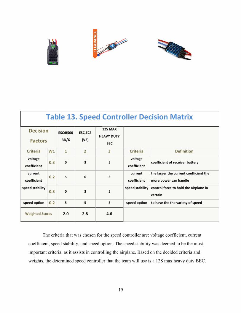
Table 13. Speed Controller Decision Matrix
Decision
Factors
ESC:B500
3D/X
ESC,EC5
(V2)
12S MAX
HEAVY DUTY
BEC
Criteria Wt. 1 2 3 Criteria Definition
voltage
coefficient 0.3 0 3 5
voltage
coefficient coefficient of receiver battery
current
coefficient 0.2 5 0 3
current
coefficient
the larger the current coefficient the
more power can handle
speed stability 0.3 0 3 5
speed stability control force to hold the airplane in
certain
speed option 0.2 5 5 5 speed option to have the the variety of speed
Weighted Scores 2.0 2.8 4.6
The criteria that was chosen for the speed controller are: voltage coefficient, current
coefficient, speed stability, and speed option. The speed stability was deemed to be the most
important criteria, as it assists in controlling the airplane. Based on the decided criteria and
weights, the determined speed controller that the team will use is a 12S max heavy duty BEC.
19
Page 21
m. Motor Size
Motor Size Weighted Decision Matrix x
Decision
Factors Brushed Brushless
Which wing configuration do I use?
Criteria Wt. 1 2 Criteria Definition
Weight 0.10 3 4 Weight Overall weight that the motor adds to the plane
Thrust 0.30 3 5 Thrust The amount of reaction force that the motor
can create using the propeller
Thrust to
Weight
Ratio
0.40 4 4 Thrust to
Weight Ratio
The ratio between how much weight the motor
adds to how much thrust it creates
Control 0.20 3 4 Control How easy the pilot can control the plane's speed
Weighted Scores 3.4 4.3
The brushless motor is necessary because the control and thrust to weight ratio are better
than the brushed motor. The brushed motor just does not produce enough control or thrust which
makes the brushless motor much better for the aircraft. The brushless motor is significantly more
efficient than the brushed motor and that is why is performed better in the decision matrix.
20
Page 23
5. Updated Project Plan
Table 2: Updated Project Plan
Task W 1 W 2 W 3 W 4 W 5 W 6 W 7 W 8 W 9 W 10 W 11 W 12 W 13 W 14 W 15
Client meeting
Define problem and layout
project plan
Research design
Research protocol writing
Research parts of design
Functional diagram
Concept Generation
Decision Matrix
Sketch Parts
Pick a final design (decision
matrix)
Proof of Concept Discussion
Project Proposal Discussion
Finalize design
Problem Definition and Project
Plan Presentations
Concept Generation and
Selection Presentations
Proof of Concept
Demonstrations
Project Proposal Presentations
In the updated project plan multiple tasks have been added. The team is on track to finish
these tasks. Currently, every task has been finished up to week 8. Following week 8, the team
will focus on picking a final design for the wings, as well as roughly calculate the center of
22
Page 24
gravity of the aircraft based on certain assumptions. The team must test and build a viable set of
wings by week 12. After this is finished, the team will compile all research done this semester
and provide a report and presentation, completing the project plan.
6. Conclusions
The team has made the final decisions on many of the critical aspects for the aircraft.
This is shown in decision matrices and conceptual drawings. The Airfoil that was decided best fit
for the aircraft is S1223, this is because, has the best critical factors such as lift and stall quality.
For the sweep and taper configuration the winning design was the rectangle. This is because the
other designs are efficient when an aircraft is moving much faster than the aircraft we are
building. The landing gear configuration that is attached to fuselage with supporting bar is the
best alternative due to the strength and control that the aircraft will have in the landing and
taking off part of the competition. A fuselage was very close in the end, but the team thought the
strength and ability in changing the size easily put the rectangular prism design above the rest.
The aircraft’s stability is critical for flight so the team decided to use the twin tail design, so that
the height can be minimized with the same amount of control surfaces. When deciding the wing
placement we determined for the coefficients of drag and lift that we need from the design, the
monowing high placement was best to lift our aircraft. The lightest and best accessibility for the
payload configuration was the box with a sliding lid. There will be two types of material that will
be used to build different parts of the aircraft and the team chose wood and plastic. With all the
types of receivers the team concluded that the 6 channel receiver would have enough channels
for what is needed on our aircraft. The team also chose to use the 5 channel transmitter because it
has more than enough gains to send signals to our receiver. The high powered servo was decided
on because the aircraft must be responsive in the wind and the high powered servo will ensure
this. For the speed controller the 12s max heavy duty is necessary for the speed stability it has.
Due to how critical the weight, thrust and control is for the motor it is necessary that we use a
brushless motor for our aircraft. All of these critical designs will be implemented into the aircraft
and be modified as needed.
23
Page 25
7. References
[1] WhatWhenHow, “Tail design”, Conventional Tail, Ttail, Dual Tail, Triple Tail and Twin Tail. Available: whatwhenhow.com.
[2] National Aeronautics and Space Administration, ”structures and materials”, aircraft background, P34.
[3] P. J. Pritchard, Introduction to Fluid Mechanics 8th Edition. Fox and McDonald. Wiley, 2011.
[4] M. H. Sadraey, Aircraft design: a systems engineering approach. Hoboken, New Jersey: Wiley, 2012.
[5] “Airfoil Tools,” Airfoil Tools. [Online]. Available at: http://airfoiltools.com/. [Accessed: 2015].
24