Secretariat of the Basel, Rotterdam and Stockholm Conventions United Nations Environment Programme International Environment House 1219 Châtelaine (Geneva) Switzerland
Safe and Environmentally Sound Ship Recycling in Bangladesh
Work Package 2: Planning the Management
of Hazardous Materials
Common Hazardous Waste Treatment, Storage & Disposal Facility:
Design Options for the Environmentally Sound Management of Hazardous Waste in Chittagong, Bangladesh
Lead Author:
Prof. (Dr.) Shyam R. Asolekar Centre for Environmental Science & Engineering Indian Institute of Technology Bombay Powai, Mumbai 400 076, INDIA (Mobile) +91-98204 10443 (Phone) +91-22-2576 7867 (Fax) +91-22-2572 3480 (Email) [email protected]
14th October, 2016
i
Disclaimer
1) The views expressed in this document are those of the Consultants and are not
attributed in any way to the United Nations, the Secretariat of the Basel,
Rotterdam and Stockholm Conventions (BRS) or the International Maritime
Organization (IMO).
2) Although the techno-commercial and management-related data and insights in
this document are aided and supported by several individuals and organizations,
the views expressed in this document are solely the personal “judgements” and
“expert opinions” of the lead author of this document and no other individual or
organization associated with the author and/or this report.
ii
Acknowledgements
The contribution of Richa Singh, J M Vivek and Nitish Vishvakarma, researchers at
IIT Bombay, to this study and report is sincerely appreciated. The timely help and
support provided by Rahul Sutar, Dheeraj Kumar, Ketan Kamble and Anurag Singh
(all from IIT Bombay) is also recognized and acknowledged gratefully.
The conceptual design and costing of the proposed TSDF was reviewed and critical
comments were provided by Prof. K. Y. Maillacheruvu from Bradley University,
Peoria, State of Illinois, USA and Yogen Parikh (a freelance consultant) from the
Indian Environmental Association, Mumbai. The author would like to record his
appreciation for their significant contribution.
Inputs and comments given by Nikos Mikelis and Susan Wingfield throughout the
course of this Project have helped in making critical and significant decisions
regarding the conceptual design and costing of the proposed Common Hazardous
Waste Treatment, Storage & Disposal Facility (CHW-TSDF) presented in this report.
The author of this report and the associated research team at IIT Bombay is indebted
to both of them for their invaluable help.
We take this opportunity to record our sincere appreciation for Md Zahirul Islam and
Colleagues from BSBA, Yasmin Sultana and Md Mizanur Rahman for providing
assistance, facilitation and useful comments. Their efforts have made this document
more practical and useful.
iii
Table of Contents
1 Executive Summary . . . . . . . . . . . . 1
2 The Context . . . . . . . . . . . . 4
3 What are Hazardous Wastes? . . . . . . . . . . . . 5
4 Inventory of Hazardous wastes in Chittagong Yards and Industries
. . . . . . . . . . . . 6
5 Methodology Adopted for projection of Wastes Disposed in 10 Years of Life-Time of the TSDF
. . . . . . . . . . . . 9
6 The Tentative Design Basis for the Proposed TSDF
. . . . . . . . . . . . 12
7 Site Layout & Process Scheme of the Proposed TSDF
. . . . . . . . . . . . 14
8 Staged Approach to Development of TSDF and Capital Costs
. . . . . . . . . . . . 16
9 Caution, Riders and Uncertainties . . . . . . . . . . . . 18
10 Critical Questions to be addressed by the Government of Bangladesh
. . . . . . . . . . . . 19
11 Critical Questions to be addressed by the BSBA
. . . . . . . . . . . . 20
12 Critical Questions to be addressed by the Industry Associations and Individual Industries
. . . . . . . . . . . . 21
13 Tariff Structure of the Proposed TSDF . . . . . . . . . . . . 21
14 Conclusions and Recommendations . . . . . . . . . . . . 24
Appendix 1 Site Selection Considerations . . . . . . . . . . . . 26
Appendix 2 Technology Options for TSDF . . . . . . . . . . . . 27
Appendix 3 Requirements of the Other Machinery . . . . . . . . . . . . 30
Appendix 4 Requirements of Supporting Infrastructure and Utilities
. . . . . . . . . . . . 31
Appendix 5 System for Transportation of Wastes . . . . . . . . . . . . 33
Appendix 6 System for Chain of Command and Movement of Hazardous Wastes
. . . . . . . . . . . . 35
Appendix 7 Suggestions for Sophistication and Systemization of TSDF Management
. . . . . . . . . . . . 38
Appendix 8 Typical Organogram for the CHW-TSDF Operations
. . . . . . . . . . . . 41
Appendix 9 Co-processing & the Other Measures . . . . . . . . . . . . 42
Appendix 10 Guidance for On-site Storage . . . . . . . . . . . . 45
References and Bibliography . . . . . . . . . . . . 63
1
Common Hazardous Waste Treatment, Storage & Disposal Facility:
Design Options for the Environmentally Sound Management of Hazardous Waste in Chittagong, Bangladesh
1 Executive Summary
The inventory of hazardous wastes generated from the ship recycling industry in
Chittagong and from the surrounding industrial areas were developed through a
survey under Work Package-2 (WP-2) of the Safe and Environmentally Sound Ship
Recycling (SENSREC) Project. Tables 1 and 2 in this report have been imported
from the “Hazardous Waste Assessment Report” published as one of the earlier
deliverables under WP-2. These tables display the estimates of hazardous wastes
generated by the ship recycling yards and from other industries in Chittagong region,
respectively.
It is evident from the inventory assessment that the ship recycling sector has been
producing sizable and comparable quantities of landfillable and incinerable wastes.
However, the industrial sectors cumulatively generate nearly negligible landfillable
wastes; but generate comparatively large quantities of incinerable wastes.
The data of ships dismantled in Chittagong over the past seven years was studied
and the opinions of experts were considered before arriving at any conclusion
regarding growth rate of recycling yards. In that light it was concluded that the ship
recycling sector in Chittagong could grow at a rate of 4% in the near future.
Table 3 has been imported from the “Hazardous Waste Assessment Report” which
summarizes the expected growth rates of different industrial sectors in Bangladesh
and the corresponding comments made by different experts consulted by the team.
Clearly, the rates are different for the sectors that were a focus of this report. In the
light of expert opinion, it was concluded that the average of 6% growth rate for
industrial growth in the coming decade will be possible for Bangladesh with fair
certainty.
In any case, availability of a reliable "Common Hazardous Waste Treatment, Storage
& Disposal Facility (CHW-TSDF)" is an important requirement for effective
2
management of hazardous wastes. Like common effluent treatment plants (CETPs)
where government and industry associations/companies participate in operation and
maintenance, the operator of the CHW-TSDF facility can be a government agency,
quasi-governmental agency, an industry association, a joint venture or a private
sector company. Hazardous waste treatment is an expensive process that demands
specialized supervision and instrumentation.
It is envisaged that the development of the CHW-TSDF can be implemented by
adopting actions and expenditures in two stages. In “Stage 1”, one facility should be
constructed with landfill for the total inventory and an incinerator for ship recyclers
only, plus the proportionate wastewater treatment facility. Thus, the TSDF shall
serve as the common centralized facility for providing environmental utility services,
initially to the ship recycling yards in Chittagong and thereafter to other industries
around Chittagong, for disposing the hazardous wastes in a safe and environmentally
sound manner.
Of the land required for creating a TSDF for management and disposal of hazardous
wastes, a substantial footprint will be required to provide for several essential
services at the TSDF site. It appears that one would need a plan area of about 20
acres (8 hectare footprint) for the proposed CHW-TSDF in Chittagong.
It is recommended that the Government should provide free land and infrastructure
like water-supply, treated wastewater pipeline for disposal, power supply, approach
roads and compound wall to stop access from local communities.
The TSDF, for both stages of development, will cost approximately USD 11.5 million
(i.e. USD 6 million for Stage 1 and USD 5.5 million for Stage 2) - excluding the cost
for land, utilities and project management (Refer to Table 6 in the detailed report for
further details on cost break-up). These estimates may be amended as a result of
ongoing work. The CHW-TSDF could be built over 18 to 24 months by creating a
dedicated team by the Government of Bangladesh.
It is to be reiterated that the above calculations are assuming that there will be yearly
6% growth in industrial sectors and approximately 4% growth in ship dismantling
sector. However, this is probably not the case for each and every sector. Some may
not grow at all while some may grow beyond our expectation. In any case, the
country will progress over the years and so it is likely that the amounts of solid and
liquid wastes will grow.
In addition, there will be more sectors, generating more wastes – which will be
3
established as time progresses. However, as industries graduate to a more
progressed status, there should be waste minimization due to the application of
advanced technologies. Also, it is expected that industries will adopt reduce, recycle
and reuse-based practices (3Rs) and some minimization of emissions will happen.
These factors will escalate the generation rate of the wastes over the period of
coming 10 years - which has been assumed to be the life of the facility.
The advanced industrial sectors, including ship recycling yards and other industries,
in the future years will certainly be more thorough in sending larger quantities of
wastes to the waste management facility and the overall wastes to be handled and
treated will essentially grow in the regimes where better compliance can be achieved.
Finally, it is worth noting that the designs and estimates may contain inaccuracies
due to the approximate nature of the inventory and a host of assumptions made in
the course of development of this concept and cost estimates. Clearly, the systems
designed on the basis of such an inventory and the costing based on several
assumptions has given rise to at best “the approximate estimates”.
4
2 The Context
It is envisaged that a Common Hazardous Waste Treatment, Storage and Disposal
Facility (CHW-TSDF) for Chittagong shall serve as the common centralized facility for
providing environmental utility services to the ship recycling yards in Chittagong as
well as to other industries around Chittagong, for disposing the hazardous wastes in
a safe and environmentally sound manner.
At the outset, let us understand the glossary of typical terms used in connection with
some of the terms commonly used in the field of hazardous waste management. The
treatment, storage and disposal facilities, or TSDFs, refers to the facilities that
receive hazardous wastes for treatment, storage or disposal. The activities of a
TSDF include the following:
Treatment – The character or composition of hazardous wastes are altered in a
‘treatment process’ that follows various processes, such as incineration or
oxidation. Some treatment processes enable waste to be recovered and
reused in manufacturing settings, while other treatment processes
significantly reduce the amount of hazardous waste.
Storage – The ‘storage’ facility ensures temporarily holding of hazardous wastes
until they are treated or disposed of. Hazardous waste is commonly stored
prior to treatment or disposal, and must be stored in containers, tanks,
containment buildings, drip pads, waste piles, or surface impoundments.
Disposal – ‘Disposal’ refers to a permanent process of containing hazardous
wastes. The most common type of disposal facility is a landfill, where
hazardous wastes are disposed of in cautiously constructed units designed to
protect groundwater and surface water resources.
CHW-TSDF – A ‘Common Hazardous Waste Treatment, Storage and Disposal
Facility’ typically refers to the arrangement or setup created for several
generators of hazardous wastes. There may be an individual industrial facility
having a TSDF for their own use, in which case it will not be called a
“common” facility. There are different business models currently in operation.
The facility may be owned by a private entrepreneur as a stand-alone
“business or industry” to provide professional technical services for the
management of hazardous wastes for a variety of industries or it may be
owned and operated by the industries in a cooperative manner. The facility
may be designed to receive wastes from one sector (e.g. the CHW-TSDF in
5
Alang, India, is a dedicated facility receiving wastes only from ship
dismantling yards) or the facility may cater to several industrial sectors.
3 What Are Hazardous Wastes?
Any material becomes “waste” when it is discarded without expecting to be
compensated for its inherent value. When improperly treated, stored, transported or
disposed of or managed, these wastes may have adverse impacts on human health
or the environment. All economies generate wastes that can be hazardous to human
health and the environment.
Hazardous waste is solid waste, or combination of solid wastes, which because of its
quantity, concentration, or physical, chemical, or infectious characteristics may (a)
cause, or significantly contribute to, an increase in mortality or an increase in serious
irreversible, or incapacitating reversible, illness; or (b) pose a substantial present or
potential hazard to human health or the environment when improperly treated,
stored, transported, or disposed of, or otherwise managed (RCRA §1004(5)).
According to the United States Environmental Protection Agency (US-EPA),
hazardous waste may be defined as “posing a substantial threat to human health or
death or posing a substantial threat to human health or the environment when
improperly managed.” Waste may be defined as hazardous, which meets one of the
following four characteristics:
Ignitability - Wastes that pose fire hazards during routine management. Fires not
only present immediate dangers of heat and smoke, but also can spread
harmful particles over wide areas.
Corrosivity - Wastes requiring special containers or segregation from other
wastes because of their ability to dissolve toxic contaminants.
Reactivity - Wastes that tend to react spontaneously, to react vigorously with air
or water, to be unstable to shock or heat, to generate gases or to explode.
Toxicity - Wastes that, when improperly managed may release toxicants in
sufficient quantities to pose a substantial hazard to human health or the
environment.
Due to the lack of adequate awareness, political will and analytical capabilities, in
some developing countries hazardous wastes may be dumped together with
6
construction wastes or household wastes, resulting in a public health hazard. The
paramount challenge that needs to be addressed, though, is the amount of untreated
and abandoned hazardous wastes in many developing countries. The challenge is
far reaching in terms of both the ecology and environment as well as public health.
The major bottleneck is the lack of waste treatment, handling and disposal facilities in
these countries.
There are two schools of thought, which exist in the domain of hazardous waste
management, namely; [a] pre-process the wastes at the point of generation before
loading and transporting them to the dedicated facility; and [b] send the hazardous
wastes for direct disposal to the facility without any pre-treatment operations at the
site of generation.
In any case, availability of a reliable "Common Hazardous Waste Treatment, Storage
& Disposal Facility (CHW-TSDF)" is an important requirement for effective
management of hazardous wastes. Like common effluent treatment plants (CETPs)
where government and industry associations/companies participate in operation and
maintenance, the operator of the CHW-TSDF facility can be a government agency,
quasi-governmental agency, an industry association, a joint venture or a private
sector company. Hazardous waste treatment is an expensive process that demands
specialized supervision and instrumentation.
4 Inventory of Hazardous Wastes in Chittagong Yards & Industries
The inventory of hazardous wastes generated from the ship recycling industry in
Chittagong and from the surrounding industrial areas were developed through a
survey under Work Package-2 (WP-2) of the Safe and Environmentally Sound Ship
Recycling (SENSREC) Project. Tables 1 and 2 in this report have been imported
and adapted from the “Hazardous Waste Assessment Report” published as one of
the earlier deliverables under WP-2. These tables display the estimates of
hazardous wastes generated by the ship recycling yards and from other industries in
Chittagong region, respectively.
More specifically, as presented below, Table 1 shows an estimation of the hazardous
waste generated from the ship recycling industry in Chittagong, while Table 2
represents the quantification of hazardous waste derived from other industries in the
Chittagong region.
7
Table 1: Estimates of hazardous waste quantities generated from the Chittagong ship recycling yards, Chittagong Port (MT/yr)
Disposal Method
Recent Trend
Minimum
(MT/yr)
Recent Trend
Maximum
(MT/yr)
Average of the Range
(MT/yr)
10-yr lifetime capacity
@ 4% growth
rate (MT)
Incinerable Wastes 5,400 6,400 5,900 71,000
Landfillable Wastes
(Toxic + Inert) 7,500 10,300 8,900 107,000
Alternate gainful use
or send to Municipal Solid
Waste landfill
Nil Nil
Grand Total 14,800 178,000
It is evident from the inventory assessment that the ship recycling secor has been
producing sizable and comparable quantities of landfillable and incinerable wastes.
However, the industrial sectors cumulatively generate nearly negligible landfillable
wastes; but generate comparatively large quantities of incinerable wastes.
8
Table 2 Estimates of hazardous waste quantities generated by industries in Chittagong by waste type and disposal method (MT/yr)
Waste
Type
Total waste
generation rate
(MT/yr)
Disposal Methods
Incineration
(MT/yr)
Landfilling Alternate gainful
use or
Municipal Solid Waste landfill
(MT/yr)
Toxic waste landfill
(MT/yr)
Inert landfill
(MT/yr)
Tundish lining 25'192
25'192
ETP sludge 19'165 3'443 324
15'397
APC Dust 11'131
11'131
Contaminated solid waste 3'965 3'965
Contaminated packaging 3'626 3'626
Oily crude tank sediments 1'459 1'459
Contaminated plastic waste 1'282 707
575
Bleaching earth 910
910
Spent Lubricants 251 251
Flesh 222
222
Maintenance scrap 124 124
Oil and grease 89 89
Chemical residues 88 88
Trimming dust 72
72
Raw hides cutting 66
66
Shaving dust 54
54
Asbestos 40
40
Other contaminated materials 25 24
1
Waste glasswool & insulation 8
8
Yearly Sub-Total (MT/yr) 67'768 13'777 324 49 53'619
Episodic and aperiodic waste 678 138 3 0 536
Yearly Total (MT/yr) # 68'600 14'000 400 54'200
10-yr lifetime capacity @ 6% growth rate (MT) #
904’200 184’500 5’300 714’400
# Rounded-off numbers
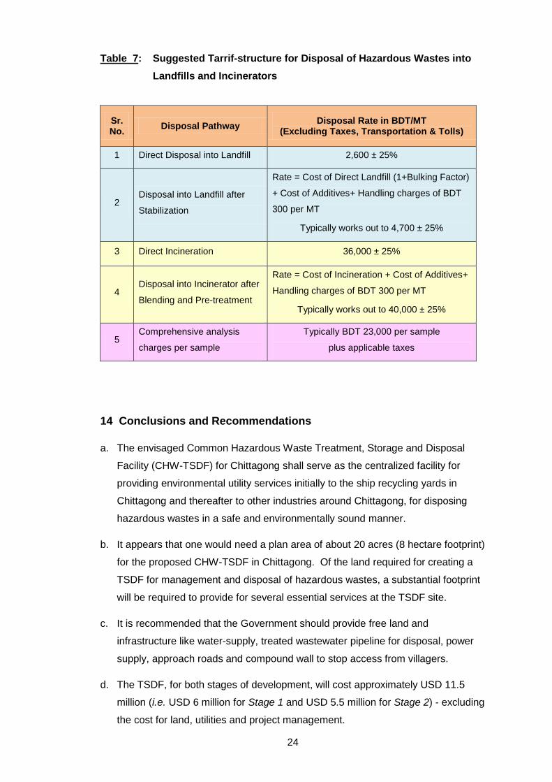
Note: In addition to the results shown above, biomedical waste generation from the hospital and health sector is estimated at 800 MT/yr (based on 6’400 beds). A dedicated facility will have to be created for it in Chittagong.
9
5 Methodology Adopted for Projection of Wastes Disposed in 10-Years of Life-Time of the TSDF
While it is understandable that it would be extremely difficult to predict the growth
rates for the future years, it was necessary to take into account some reasonable
growth rates when arriving at wastes generated over the 10-year period. Therefore,
an attempt was made by the team engaged in inventorization-related activities.
The data of ships dismantled in Chittagong over the past seven years was studied
and the opinions of experts were considered before arriving at any conclusion
regarding growth rate of recycling yards. In that light it was concluded that the ship
recycling sector in Chittagong could grow at a rate of 4% in the near future.
Table 3 has been imported from the “Hazardous Waste Assessment Report” which
summarizes the expected growth rates of different industrial sectors in Bangladesh
and the corresponding comments made by different experts consulted by the team.
Clearly, the rates are different for the sectors that were a focus of this report. In the
light of expert opinion, it was concluded that the average of 6% growth rate for
industrial growth in the coming decade will be possible for Bangladesh with fair
certainty.
Table 3: Expected growth rates of different industrial sectors in Bangladesh
Industry
Sector
Sector growth
projection Comment on growth rate
Cable 3-5%. Registered and unregistered cable manufacturers are growing in
number due to the ship breaking activities. The demand is on a rise
due to housing and industrial expansions. Eastern cables has a
higher installed capacity than what it currently produces and will
increase production as demand increases.
Cement 4-6% Though the production capacity is higher than local demand, the
export growth is compelling. The industries in Chittagong are
planning to expand. Year on year growth basis the growth is
expected to be between 4-6%.
10
Industry
Sector
Sector growth projection
Comment on growth rate
Chemical 10-12% During the inventory survey, the major players in this sector have
reported about 10% year on year growth.
Fertilizer 2-5% Most of the fertilizer industries are remaining closed for a
considerable portion of the year due to shortage in natural gas
supply. The grim business outlook prevents new investment. Since
the government is planning to import LNG in the near future, the
situation may change.
Glass 7-8 % It was heard from PHP glass that they are going to double their
capacity. We can consider 7-8 percent growth to accommodate the
doubled capacity.
Paints 7-10% Elite paint, Berger paints, etc. are reporting a steady growth rate of
7-10%.
Paper 10-12% There is still considerable potential of growth. In the new exclusive
economic zones (EEZs), considerable investments are made in the
ready-made garment sector, which consumes a lot of paper. Due to
the proximity to the port, pulp based paper industries prefer
Chittagong as a location. The sector is supposed to double with the
doubling of the ready-made garment sector.
Refinery 7-8% Installed capacity of ERL will be tripled in the next 3-5 years. As the
country’s demand is increasing, new refineries from the private or
public sector may come into play in next ten to twenty years.
Growth rate of 7% is considered to adjust the tripling of capacity of
ERL.
Rerolling 7-10% Current production surplus is more than 50% of the total domestic
demand. However, the export is increasing. Therefore, potential for
growth exists. In our recent visit to BSRM we came to know that
they are doubling their capacity. Other existing big players are also
establishing new facilities while new rerolling mills are also in the
process of establishment. We can consider 7-10% year on year
growth to reflect the planned expansion.
11
Industry
Sector
Sector growth projection
Comment on growth rate
Tannery 8-10% There were 19 tanneries of which 17 have been closed. The
remaining two have halted production due to ban by DoE for not
having ETP. One is establishing an ETP to remain in the business
besides doubling the capacity. If the TSDF is established, the
possibility of new entrants increases. Therefore, it is reasonable to
consider a 10 year doubling time which is equivalent to 8-10% year
on year growth.
Textile 10-12% Many new exclusive economic zones (EEZs) are planned, with a
number of them in Chittagong, in which considerable investments
are made in the ready-made garment sector. 10-12% growth rate
will hold, if everything remains calm, since the industry is doubling
in five years on an average.
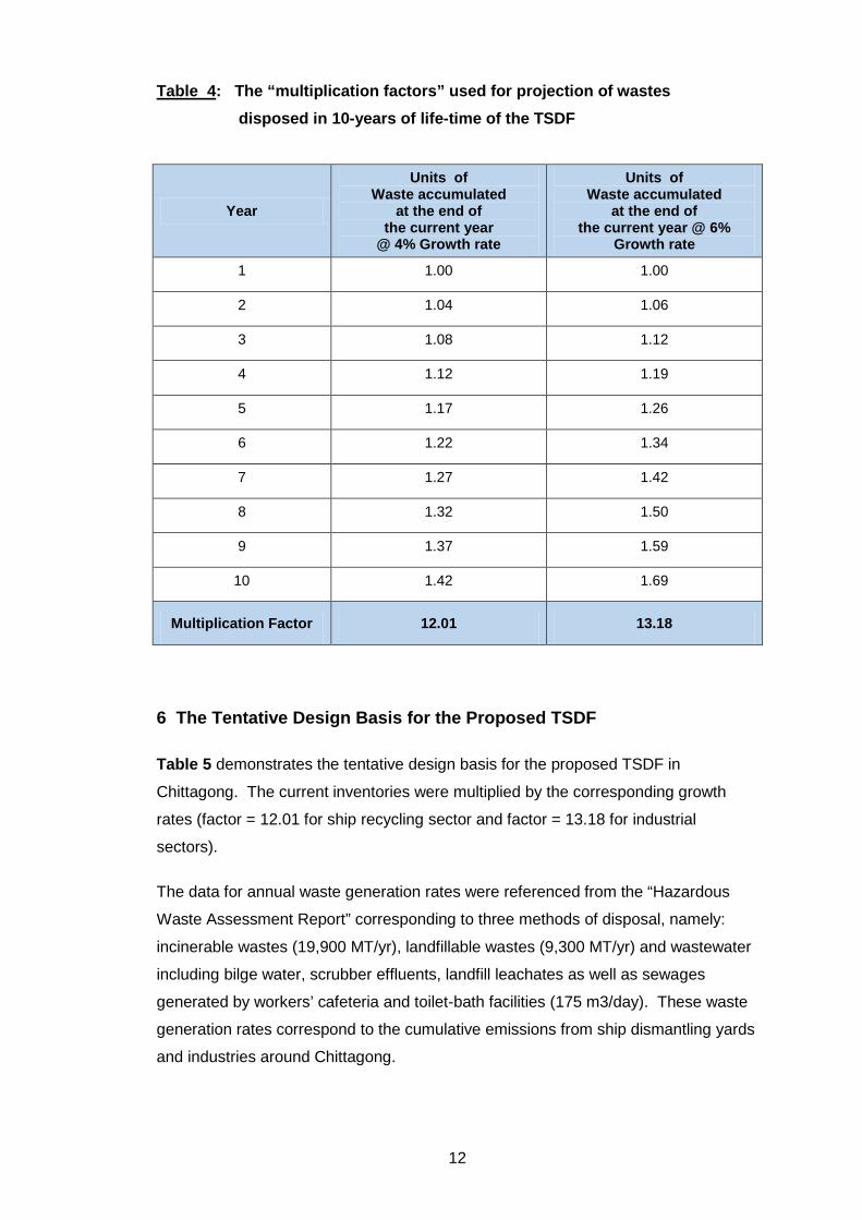
The methodology adopted for calculation of the “multiplication factor” to be used for
the projection of wastes disposed in 10-years of life-time of the TSDF is displayed in
Table 4.
A 4% growth rate (for growth in compound proportions) was assumed for the ship
recycling sector and 6% growth rate was assumed for the industrial sectors and the
following multiplication factors were estimated over the life-time assumption of 10-
years by using the factors shown in Table 4.
It is clear from the above table that the current inventory of the ship recycling industry
should be multiplied by 12.01 to arrive at a ball-park 10-year projection of total waste
to be disposed of in the facility over its lifetime at the rate of 4% growth. Similarly,
the current inventory of industrial sectors should be multiplied by 13.18 to arrive at a
ball-park 10-year projection of total waste to be disposed of in the facility over its
lifetime at the rate of 6% growth.
12
Table 4: The “multiplication factors” used for projection of wastes disposed in 10-years of life-time of the TSDF
Year
Units of Waste accumulated
at the end of the current year
@ 4% Growth rate
Units of Waste accumulated
at the end of the current year @ 6%
Growth rate
1 1.00 1.00
2 1.04 1.06
3 1.08 1.12
4 1.12 1.19
5 1.17 1.26
6 1.22 1.34
7 1.27 1.42
8 1.32 1.50
9 1.37 1.59
10 1.42 1.69
Multiplication Factor 12.01 13.18
6 The Tentative Design Basis for the Proposed TSDF
Table 5 demonstrates the tentative design basis for the proposed TSDF in
Chittagong. The current inventories were multiplied by the corresponding growth
rates (factor = 12.01 for ship recycling sector and factor = 13.18 for industrial
sectors).
The data for annual waste generation rates were referenced from the “Hazardous
Waste Assessment Report” corresponding to three methods of disposal, namely:
incinerable wastes (19,900 MT/yr), landfillable wastes (9,300 MT/yr) and wastewater
including bilge water, scrubber effluents, landfill leachates as well as sewages
generated by workers’ cafeteria and toilet-bath facilities (175 m3/day). These waste
generation rates correspond to the cumulative emissions from ship dismantling yards
and industries around Chittagong.
13
Table 5: Tentative "Design Basis” for the proposed TSDF in Chittagong
Sr No.
Disposal Method
Estimated Inventory Tentative Design Basis
From the ship
breaking yards
(MT/year)
From the industrial
areas
(MT/year)
From ship
breaking yards
10-yr
lifetime capacity @
4% growth rate
(MT)
From industries
10-yr lifetime
capacity @ 6%
growth rate (MT)
Total Waste
10-yr lifetime capacity
(MT)
1 Incinerable
Wastes 5,900 14,000 71,000 184,500 255,500
2
Toxic & Inert
Landfillable
Wastes
8,900 400 107,000 5,300 112,300
3
Bilge water
+ Scrubber
Effluents +
Landfill
Leachates +
Sewage?
100 m3/day 75 m3/day 0.45
million m3 0.35
million m3 0.80
million m3
As stated earlier, the growth rate of 4% (for growth in compound proportions) was
assumed for the ship recycling sector and 6% growth rate was assumed for the
industrial sectors and the appropriate multiplication factors were used to estimate the
cumulative quantities of wastes to be subjected to the proposed TSDF over the life-
time assumption of 10-years of the facility.
14
7 Site Layout and Ground Plan of the Proposed TSDF
The site layout and ground plan for a typical TSDF has been presented below in
Figure 1.
Figure 1: Layout and the ground plan for a typical TSDF site (Legend for the layout can be found on the next page)
HIGHWAY HIGHWAY
12
LANDFILL CELLS FOR INERT WASTES
10
TANKFARM 11
ETP
9b INCINERATOR 2
13a
LANDFILL CELLS FOR
TOXIC WASTES (ZONE 1)
13b
LANDFILL CELLS FOR TOXIC WASTES
(ZONE 2)
2
MEETING AREA
7 ADMIN
BUILDING
14
5
4
6 PARKING
FOR TRUCKS & TANKERS
VISITOR PARKING
WORKING SPACE FOR
TEMPORARY STORAGE &
MAINTENANCE WORK
GREEN BELT
GR
EEN
BEL
T
16 FIRE
STATION
15
9a
INCINERATOR 1
3
GR
EEN
BEL
T
8 STORAGE, BLENDING
& HOLDING AREA
1 COMPOUND WALL COMPOUND WALL
COMPOUND WALL COMPOUND WALL
15
Legend for Figure 1 i.e. the Ground Plan of a typical TSDF Site:
1 Secure entrance gate
2 Security and reception office
3 Weigh bridge
4 Quality & quantity records office, Laboratory
5 Dining hall, Workers' recreation, Doctor's room
6 Parking for trucks and tankers
7 Administrative building
8 Hazardous waste storage, blending and holding zone
9 Incineration plant, Stage 1 (Location 9a) and Stage 2 (Location 9b)
10 Tank farm to hold liquid wastes and waste oils
11 Effluent Treatment Plant (ETP)
12 Landfill cells for inert wastes
13 Landfill cells for toxic wastes (Zone1, Location 13a and Zone 2
Location 13b)
14 Toilet-Bath complex
15 Overhead Water Tank
16 Fire Station
The schematic representation is not to scale and it has been presented for illustrating
a typical configuration and layout of the landfills, incinerators, effluent treatment farm
vis-à-vis other utilities and administrative infrastructure. It is well recognized that the
real-life situation would have a non-regular geometric shape to the assigned 10-15
hectare plot of land for building the facility.
16
8 Staged Approach to Development of the TSDF and Capital Costs
It is envisaged that the development of the TSDF can be implemented by adopting
actions and expenditures in two stages. In “Stage 1”, one facility shall be constructed
with landfill for the total inventory and an incinerator for ship recyclers only plus the
proportionate wastewater treatment facility.
As shown in Table 6, it appears that one would need a plan area of about 20 acres
(8 hectare footprint) for the proposed CHW-TSDF in Chittagong. The TSDF, for
Stage 1 of development, will cost approximately USD 6 million - excluding the cost
for land, utilities and project management.
In “Stage 2”, however, the facility established in Stage 1 can be augmented by
establishing the additional incinerator for industrial wastes. It can be established
adjacent to the “Stage 1” incinerator meant for ship recyclers. In that case, the
incremental wastewater generated by the scrubber of the new facility will be treated
by augmenting and upgrading the existing Effluent Treatment Plant (ETP)
(established in Stage 1). Also, separate land will not be required because it is
recommended in the proposed approach that adequate land should be provided for
up-front in Stage 1 itself.
As shown in Table 6, it appears that one would need additionally USD 5.5 million for
establishing the incinerator and the appropriate augmentation of the facility during
development of “Stage 2”.
Yet another approach could be that the new incinerator can be established adjoining
the industrial wastewater treatment facility (Common Effluent Treatment Facility i.e.
CETP) in an industrial zone in Chittagong so that wastewater generated by this
incinerator can be subjected to treatment in that CETP.
If funding for both stages were to be made available at the start of the project, it is
recommended that “Stages 1 and 2” be implemented together.
Finally, it is useful to note that the costs depicted in Table 6 are approximate
because they are based on several assumptions. For example, the base costing was
referenced to today’s costs in India to build such a project. There are several other
techno-commercial assumptions made to arrive at the costs in million USD –
including that of 8% inflation and also for the growth rates of the ship recycling
industry and other industries in Bangladesh.
17
Table 6: Break-up of land and capex requirements for the proposed TSDF in Chittagong corresponding to both the stages
Stage 1
Sr No
Waste to be treated and disposed off
Land Needed for landfill cells plus approach road and working space
adjoining it (plan area)
hectare i.e. ha
Land Needed for landfill cells plus approach road and working space
adjoining it (plan area) acre i.e. ac
Funds Needed in
2016 million USD
1 Landfillable Wastes 1.40 3.46 2.50
2 Incinerable Wastes (Stage 1)
1.50 3.71 1.90
3 Bilge water + Scrubber Effluents + Landfill Leachates + Sewage?
1.00 2.47 0.22
4 Civil Work, storage and blending sheds, site development, infrastucture, chemical laboratory (modest), fire fighting facility, green belt, etc.
3.90 9.64 1.18
TOTAL = 7.80 19.28 5.80
hectare Acre million USD
Stage 2
5 Incinerable Wastes (Stage 2)
Nil Nil 4.92
6 Remodel and augment the existing ETP to treat Scrubber Effluents from the new incinerator
Nil Nil 0.28
7 Additinal Civil Work, storage and blending sheds for the new incinerator
Nil Nil 0.37
TOTAL = Nil Nil 5.57
hectare Acre million USD
18
9 Cautionary Notes
It appears that one would need a plan area of about 20 acres (8 hectare footprint) for
the proposed CHW-TSDF in Chittagong. It is recommended that the Government
should provide free land and infrastructure like water-supply, treated wastewater
pipeline for disposal, power supply, approach roads and compound wall to stop
access from villagers. Then, the TSDF can be built over 18 to 24 months and it will
cost approximately USD 11 million (excluding the cost for land, utilities and project
management). It should be noted that these estimates may be amended as a result
of ongoing work.
Of the land required for creating a TSDF for management and disposal of hazardous
wastes, a substantial footprint will be required to provide for the following services at
the TSDF site:
a. Analytical laboratory, waste receiving and handling
b. Parking of trucks, tankers and vehicles of workers and visitors
c. Blending of wastes and pre-processing
d. Thermal treatment
e. Treatment of leachates & effluents
f. Organization and administration
g. Worker’s dining, recreation, welfare and medical facility
h. Fire safety, disaster management, space for providing ring road around the
entire plot for emergency use in case of fire, flood, explosion and accidents
i. Green belt of minimum 20 meter width (40 meter width would be even better);
all around the facility
The designs and estimates may contain inaccuracies due to the approximate nature
of the inventory. Systems designed on the basis of such an approximate inventory
and the costing based on that could be at best approximate.
It is to be noted that the above calculations are assuming that there will be yearly 6%
growth in industrial sectors and about 4% growth in ship dismantling sector.
However, it is probably not true about each and every sector. Some may not grow at
all while some may grow beyond our expectations. In any case, the country will
progress over the years and so it is likely that the amounts of solid and liquid wastes
will grow.
19
In addition, there will be more sectors, generating more wastes – which will be
established as the time progresses. However, as the industries graduate to more
progressed status; there will be waste minimization due to application of advanced
technologies. Also, it is expected that industries will practice reduce, recycle and
reuse-based practices (3Rs) and some minimization of emissions will happen.
These factors will escalate the generation rate of the wastes over the period of
coming 10 years - which has been assumed to be the life of the facility.
The advanced industrial sector in the future years will certainly be more thorough in
sending larger quantities of wastes to the waste management facility and the overall
wastes to be handled and treated will essentially grow in the regimes where better
compliance will be achieved. Although, one cannot predict that the overall
influencing factors will compensate with each other and the net change in yearly
production of wastes will be insignificant or otherwise. In summary, no one can
predict the future. Effort has been made in this exercise to use the best “defendable”
basis in the given situation for designing the CHW-TSDF.
Finally, it is envisaged that the Common Hazardous Waste Treatment, Storage &
Disposal Facility (CHW-TSDF) will be an “Integrated Hazardous Waste Management
Facility”. What makes any such facility an “integrated” one? Any typical CHW-TSDF
project would need to address the following issues seriously and thoroughly:
1. Role of Waste Generators
2. Role of Waste Transporters
3. Operations and Work Zones
4. Resources Required & Emissions
5. Health, Safety & Environmental Issues
6. Financial & Business-related Issues
10 Critical Questions to be Addressed by the Government of Bangladesh
The Government Authorities in Bangladesh will have to facilitate the creation of the
TSDF by providing free land and infrastructure like water-supply, treated wastewater
pipeline for disposal, power supply, approach roads and compound wall to stop
access from villagers. In this context, four important questions need to be answered:
20
1. Whether the Government of Bangladesh would be imposing requirements for
treatment, storage and disposal of hazardous wastes generated by the ship
recycling yards in Chittagong once the TSDF is ready to receive hazardous
wastes from the ship recycling industry?
2. Whether the Government of Bangladesh would be imposing the requirements for
treatment, storage and disposal of hazardous wastes generated by the industries
in the City of Chittagong and the surrounding industrial clusters in the adjoining
peri-urban areas once the TSDF is ready to receive hazardous wastes from these
industries?
3. What plans the Government of Bangladesh would have for providing about 20
acres (8 hectare) suitable land free of cost for building this project and facilitate
the CHW-TSDF project by providing infrastructure like water-supply, treated
wastewater pipeline for disposal, power supply, approach roads and compound
wall?
4. Is the Government of Bangladesh able to contribute any proportion of funds
towards what is needed for the development of the CHW-TSDF?
11 Critical Questions to be Addressed by the BSBA
The BSBA may contribute to the development of the Common Hazardous Waste
Treatment, Storage and Disposal Facility (CHW-TSDF) for Chittagong. In this
context, three important questions need to be answered by BSBA:
i) Whether the BSBA would recognize the inevitability of creating the Common
Hazardous Waste Treatment, Storage and Disposal Facility (CHW-TSDF) for
responsible management of wastes generated by the ship recycling yards in
Chittagong?
ii) Whether the BSBA would be imposing the requirements for treatment, storage
and disposal of hazardous wastes generated during ship recycling onto the
yards in Chittagong?
iii) Is the BSBA able to contribute any proportion of funds towards what is needed
for the development of the CHW-TSDF?
21
12 Critical Questions to be Addressed by the Industry Associations and Individual Industries
Industry associations and the large polluting industries (individually) may also
contribute to the development of a Common Hazardous Waste Treatment, Storage
and Disposal Facility (CHW-TSDF) for Chittagong. In this context, three important
questions need to be answered by the industry associations and the large polluting
industries:
a) Whether the association and industries would recognize the inevitability of
creating the Common Hazardous Waste Treatment, Storage and Disposal
Facility (CHW-TSDF) for responsible management of wastes generated by them
in and around Chittagong?
b) Whether the industry associations and the large polluting industries would be
imposing the requirements for treatment, storage and disposal of hazardous
wastes generated during their operations in and around Chittagong?
c) Are industry associations and individual large industries willing to contribute any
proportion of funds towards what is needed for the development of the CHW-
TSDF?
13 Tariff-structure for the Proposed TSDF
It is obvious that the costs per unit weight (or volume) of the wastes received at the
Common Hazardous Waste Treatment, Storage and Disposal Facility (CHW-TSDF)
will have to be decided in a rational manner and in consultation with the significant
stakeholders. Who will be the significant stakeholders – whose opinions must be
incorporated in a well-articulated protocol set-up for deciding the tariff rates? This
can only be answered after completing the following two important steps:
i) The critical questions asked to the three most important stakeholders should be
answered satisfactorily (refer to the preceding sections, viz. sections 10, 11 and
12).
ii) The Ministry of Industries, Ministry of Environment and the other empowered
ministries and departments (or agencies) in the Government of Bangladesh will
have to collectively agree upon the nature, character and functions of the
empowered agency or enterprise or some institutional arrangement for
undertaking the task of building and operating the proposed CHW-TSDF.
22
In other words, once the so-called “business model” is decided and once the extent
of the involvement of the Government is finalized, it would be easier to lay down the
protocol for deciding the tariff rates. In parallel, efforts are underway wherein
different business cases are being developed for the proposed TSDF and an attempt
will be made to compare them – especially in the context of Bangladesh.
In any case, the Committee empowered to decide the tariff structure will certainly
consider the costs associated with operating the infrastructure of landfills and
incinerators. They will include in the abovementioned operating costs the share of
prorated servicing of the loans for setting up of the TSDF for meeting the capex costs
(if any) as well as the appropriate taxes and levies as per the laws of the land.
In addition, it is recommended that the costs incurred in establishing as well as
operating some specific components have to be taken into account while deciding
the tariff rates. Some significant cost overheads associated with the operation and
maintenance of a typical TSDF are listed below to provide practical guidance to the
Committee empowered to decide the tariff structure:
1. Financial Assurance for Closure/Post-Closure Care: After the completion of the
active operational life of a TSDF, the operator has to ensure closure and proper
post-closure monitoring of the facility for approximately 30 years. They must
prepare a cost estimate that reflects how much it would cost to hire a third-party
contractor to close the facility. These estimates provide the base figure for the
amount of financial assurance a facility must provide:
• Cost Estimates: It must reflect the cost of hiring a third party to conduct all
activities outlined in the closure and post-closure plans. Costing based on
projected costs for an entire post-closure period of 30 years, unless reduced
or extended by the implementing agency.
• Cost Adjustments: Closure and post-closure cost estimates must be adjusted
annually for inflation until closure is completed.
2. Accident Liability Requirements: TSDF owners and operators must also be able
to compensate third parties for bodily injury or property damage that might result
from hazardous waste management at a facility. Funds should be available to
compensate affected third parties suffering bodily injury or property damage. All
TSDFs must demonstrate liability coverage for sudden accidents. In addition,
TSDFs with land-based units (e.g., landfills) must also demonstrate liability
coverage for non-sudden accidents.
3. Financial Assurance for Workforce: Welfare policies for the technical and non-
technical work force along with capacity building and skill upgradation are
23
essential for effective organization and administration. Financial issues include
capital expenditure, operational and maintenance cost, other financial assurance
etc. are to be taken into account for smooth operation of the CHW-TSDF.
4. Transportation and Handling of the Wastes by a Skilled Workforce: Hazardous
wastes should be transported and handled under skilled supervision and by a
trained labor force. The manpower engaged in handling the wastes should be
given proper training such as fire fighting, spill control, emergency reporting etc.
The capacity building and training of the non-administrative workforce (labourers
and drivers) will also add to the cost incurred in operation.
5. Occupational Health and Safety Considerations: The cost of medical treatment for
the workforce is borne by the owner of the facility. This should include an on-site
medical facility, annual and half-yearly health checkups and compensatory
provisions. The facility should take all the measures to comply with national and
international labour acts. In addition, workers engaged in special wastes handling
such as asbestos removal should undergo pre-employment and periodical medical
examinations at regular intervals to ascertain whether they are medically fit to
undertake the activity.
6. Cost of Installing Supportive Infrastructure at the TSDF: There is a requirement
for supporting infrastructure and equipment for the smooth functioning of TSDF
operations. These installations include an effluent treatment plant for wastewater
and leachate treatment, and environmental monitoring and mitigation measures
for prevention of air, water (surface and ground) and soil pollution.
7. Environmental audits should also be routine activities in TSDFs to check the
compliance and competence of the plant. Green belts or the buffer zones are
required to be installed in the facility for trapping emissions and particulate matter
and to add to the aesthetic appeal of the facility.
In summary, the tariff rates for hazardous waste disposal are generally decided on
the basis of the quantity and type of the wastes. The waste disposal processes are
mainly of three types, namely landfilling, stabilization and incineration. The above
listed factors should also be taken into consideration while estimating the total
disposal cost along with applicable charges like ESCROW charges (for post-closure
monitoring of the facility), toll charges for interstate movement of wastes, handling
charges and other applicable costs. The typical tariff structure in Table 7 below
depicts the rates actually charged currently by the CHW-TSDF businesses in India.
24
Table 7: Suggested Tarrif-structure for Disposal of Hazardous Wastes into Landfills and Incinerators
Sr. No. Disposal Pathway Disposal Rate in BDT/MT
(Excluding Taxes, Transportation & Tolls)
1 Direct Disposal into Landfill 2,600 ± 25%
2 Disposal into Landfill after
Stabilization
Rate = Cost of Direct Landfill (1+Bulking Factor)
+ Cost of Additives+ Handling charges of BDT
300 per MT
Typically works out to 4,700 ± 25%
3 Direct Incineration 36,000 ± 25%
4 Disposal into Incinerator after
Blending and Pre-treatment
Rate = Cost of Incineration + Cost of Additives+
Handling charges of BDT 300 per MT
Typically works out to 40,000 ± 25%
5 Comprehensive analysis
charges per sample
Typically BDT 23,000 per sample
plus applicable taxes
14 Conclusions and Recommendations
a. The envisaged Common Hazardous Waste Treatment, Storage and Disposal
Facility (CHW-TSDF) for Chittagong shall serve as the centralized facility for
providing environmental utility services initially to the ship recycling yards in
Chittagong and thereafter to other industries around Chittagong, for disposing
hazardous wastes in a safe and environmentally sound manner.
b. It appears that one would need a plan area of about 20 acres (8 hectare footprint)
for the proposed CHW-TSDF in Chittagong. Of the land required for creating a
TSDF for management and disposal of hazardous wastes, a substantial footprint
will be required to provide for several essential services at the TSDF site.
c. It is recommended that the Government should provide free land and
infrastructure like water-supply, treated wastewater pipeline for disposal, power
supply, approach roads and compound wall to stop access from villagers.
d. The TSDF, for both stages of development, will cost approximately USD 11.5
million (i.e. USD 6 million for Stage 1 and USD 5.5 million for Stage 2) - excluding
the cost for land, utilities and project management.
25
e. It should be noted that these estimates may be amended as a result of ongoing
work. If the above facilitation is organized, the CHW-TSDF can be built over 18
to 24 months by creating a dedicated team by the Government of Bangladesh.
f. It is to be noted that the above calculations are assuming that there will be yearly
6% growth in industrial sectors and about 4% growth in the ship dismantling
sector. However, rates of growth may vary by sector. Some may not grow at all
while some may grow beyond our expectations. In any case, the country will
progress over the years and so it is likely that the amounts of solid and liquid
wastes will grow.
g. The designs and estimates may contain some inaccuracies due to the
approximate nature of the inventory. Systems designed on the basis of such an
approximate inventory and the costing based on that could be at best
approximate.
h. In addition, there will be more sectors, generating more wastes – which will be
established as the time progresses. However, as the industries graduate to more
progressed status, there will be waste minimization due to application of
advanced technologies. Also, it is expected that industries will promote reduce,
recycle and reuse-based practices (3Rs).
i. These factors will escalate the generation rate of the wastes over the period of
coming 10 years - which has been assumed to be the life of the facility.
j. The advanced industrial sector in the future years will certainly be more thorough
in sending larger quantities of wastes to the waste management facility and the
overall wastes to be handled and treated will essentially grow in the regimes
where better compliance is achieved.
26
Appendix 1
Site Selection Considerations
Site selection is a complex process involved in the design of CHW-TSDFs that
incorporates numerous criteria, factors and regulations. Those selecting potential
sites should be mindful of the potential impacts to the surrounding areas of CHW-
TSDF operations as well as the proximity of the site to waste generating industries.
The location of CHW-TSDF should be carried out on the basis of water bodies,
highways, flood plains, critical habitat area, wetlands, airports, water supply wells,
and coastal regulation zone and groundwater table. Areas of permitted waste
management units and facilities where treatment, storage, or disposal of hazardous
waste will be conducted cannot be located within an area of a fault that has
experienced movement any time during the Holocene epoch or floodplain or salt
dome formations, salt bed formations, or underground mines or caves.
The site selection shall be carried out on the basis of topographic maps, soil maps,
transportation maps, groundwater and flood plain maps, wind rose diagrams, land
use and water use plan, aerial and satellite imaging, rainfall and seismic data,
preliminary boreholes and geophysical investigations. Sub-soil, hydro-geological,
topographical and seismic investigations must be carried out at site to understand the
nature of site. The Environment Impact Assessment (EIA) studies are essential
aspects for clearance which include scoping, public hearing, impact assessment and
potential damage to wildlife, vegetation, crops and physical structures.
A thick impervious layer between the bottom of the landfill and top of the groundwater
table, sufficiently big size to have 20 years of operation, good dispersal of air
pollutants, public acceptance, safe distance from residential arears (present and
future) are the major factors that should be taken under consideration while siting a
hazardous wastes TSDF.
27
Appendix 2
Technology Options for TSDF
Wastes Storage: Hazardous waste is commonly stored prior to treatment or
disposal, and must be stored in containers, tanks, wastes piles etc. maintained as
per the guidelines of pollution control authorities. The storage sheds may be of two
types: “Temporary” and “Intractable”. Intractable storage sheds are provided for
complex wastes (if there is any discrepancy observed in the wastes or disposal
criteria). The storage area may consist of different cells for storing different kinds of
hazardous wastes. In designing these cells, all the safety considerations should be
taken into account.
Storage area for incinerable wastes should be provided with the flameproof electrical
fittings, automatic smoke, heat detection system, adequate fire fighting systems for
avoiding any kind of mishap (CPCB, 2010a). Unloading of wastes in storage sheds
should only be done under the supervision of the well trained and experienced staff.
Proper fork-lifters, gantry, chain shackles, cranes, suction pumps with non-flammable
electrical connections be made available (CPCB, 1999). The regulatory
requirements for these types of storage units are found in title 40 of the Code of
Federal Regulations (CFR) in part 264 and part 265 (USEPA 40 CFR §264 and
§265, 2014).
Treatment: Un-stabilized wastes may contribute potentially in the generation of
hazardous leachate, which lead to the contamination ground water system. The
contaminants constituting the wastes must be physically and chemically bound by
some material so that there would be no risk of consolidated stress and leaching of
hazardous contaminants.
Most commonly used pre-treatment techniques include solidification, stabilization,
chemical fixation and encapsulation. Pre-processing technologies such as S/S
technique can be used for immobilization of contaminants preferably heavy metals,
but it can also be used for different waste streams including organic waste also. The
various methods for treating the wastes before its final disposal into secured landfills
are as follows:
• Solidification: Solidification is a process that involves the mixing of additive
material in the wastes in order to convert the wastes mix into solid monolith like
28
structure. It includes physical dewatering of the wastes and the improvement of
the physical properties such as strength, compressibility, and permeability. It is
generally applied to such wastes in which there is high moisture content but no
heavy metal concentration (ETP Sludge from steel wire industries).
• Stabilization: Stabilization is a term, which includes dewatering/solidification as
well as chemical bonding of the additive material/particles with the contaminants.
The contaminants of the wastes samples get converted into chemically more
stable form. It is usually done for wastes containing toxic metals such as lead,
chromium, mercury, nickel etc.
• Encapsulation: Encapsulation is defined as the enclosure or entrapment of the
wastes by some material such as chemically bonded phosphate ceramic
encapsulation, polyethylene encapsulation, Sulphur polymer stabilization/
solidification.
Disposal of Wastes into Landfills: There are mainly two methods for final disposal
of hazardous wastes; disposal in secured landfills and thermal treatment by
incineration. Thermal oxidation through incinerator is one of the proven technologies
for destruction of hazardous waste in all the forms i.e. solid/semi-solid/liquid and
gaseous, based on the feeding system, so as to render them innocuous in the form
of non-toxic and non hazardous residues.
Hazardous wastes landfills are defined as waste disposal unit, which is designed and
constructed in such a way that it causes minimum impact to the environment (Dutta
et al., 2006). Landfill shall have to be designed and constructed as per the
guidelines of pollution control authorities. Components of Secure Engineered Landfill
are liner system, leachate collection and removal system, leak detection system,
daily/ intermittent cover, gas removal system, capping and closure system, storm
water drainage system and redundant liner at bottom.
Disposal of Wastes through Thermal Processes: Destruction of complex
hazardous waste requires knowledge to judge the compatibility of various wastes for
the purpose of homogenisation of waste to be fed to the incinerator. Operation &
maintenance of thermal processes and pollution control devices at the incinerator
demands skill and experience with respect to compliance with the environmental
regulations prescribed for the common hazardous waste incineration facilities.
Various components of common incineration facility include proper transportation,
storage, analytical laboratory facilities, feeding mechanism, incineration system
29
(rotary kiln & post combustion chamber), gas cleaning system, tail-gas monitoring
facilities with automatic on-line monitoring & control facilities, ash/slag management,
bleed/ scrubber liquor management and measures for health protection of workers
(UNEP, 2003).
30
Appendix 3
Requirements of the Other Machinery
A treatment, storage and disposal facility requires the following operational
machinery:
Handling of Wastes: Several equipment for earth moving and material handling are
required for unloading of wastes from trucks and tankers as soon as the transporters
arrive at the facility. Also, the specialized equipment are required for blending and
charging the wastes into thermal treatment. In addition, several dedicated vehicles
and material handling facilities would be required for transporting and loading the
hazardous wastes into landfill cells. The following listing is not comprehensive but
highlights some of the essential components: e.g. proper fork-lifters, gantry, cranes,
suction-pumps with flammable electrical connections electrical fittings, dozers,
compacters, back-hoe loaders and DG sets.
Equipment Required in Laboratory: A typical modern laboratory needs several
analytical instruments to undertake comprehensive analyses as well as for
conducting finger printing tests. Some of the more important analytical equipment
are: AAS graphite furnace, AOx analyser, TKN analyzer, GC with ECD, water
purification system with RO, fume hoods, precision balances, UV-VIS double beam
spectrophotometer, voltage regulator, noise level monitor, glove box, meteorological
data acquisition system, refrigerator, continuous extractor, fax/telex, muffle furnace,
hot air over, freezer, Kjeldhal apparatus, air compressor, pH meter, evaporators,
COD assembly, vacuum pump, stack emission monitoring kit, microwave digester,
conductivity meter, high volume air sampler with RSPM, micropipettes, Millipore
suction system for SS, toxic gas monitors, dragger tube & app. Set, BOD incubator,
centrifuge, flask shaker, heating mantles, magnetic strirrer with hot plates, rotary
shaker, stop watch, water bath, flame photometer, ammonia distillation assembly,
automatic burettes, air conditioners, sampling van, electronic typewriter, zero head
space extractor, flash point analyser, bomb calorimeter, volatile organic sampling,
GC/MS with purge and trap, infrastructure like DG sets, electrical fittings, air
conditioning of cold rooms etc.
Safety Equipment: Fire hydrant systems, water sprinklers, fire extinguishers and
equipment for active fire fighting.
31
Appendix 4
Requirements of Supportive Infrastructure and Utilities
The TSDF requires administrative and non-technical facilities and systems for
smooth and efficient operations. The various supporting infrastructural installations
include vehicles, mechanical and electrical workshops, operational building with
basic amenities like washrooms for administrative staff, workers and transporters,
cafeteria, medical rooms and recreation for the personnel.
The other requirements include control systems, illumination, facility approach roads
and internal service roads and their subsequent maintenance, fencing, trenches and
aesthetic maintenance of site.
Green Belt-Buffer Zone: This refers to the planting area within premises along the
boundary adjoining or abutting the TSD facility. It is a segment within the building
setback line from the road reserve line that is meant for the planting of trees and
plants which are indigenous to the site. The width of the green buffer varies
according to the road classification by Land Transport Authority. A green belt will
help to screen fugitive dust generated from the roads.
Laboratory continuously works to suggest the improvements required in the process
and system for waste handling as well as disposal. Prior to sending hazardous
waste to the facility for treatment, storage or disposal, the generators are required to
send the sample of the consignment of the hazardous waste to the operator along
with the information on the process(s) of its generation, so as to facilitate the
determination of pathway for treatment and disposal. Based on the analysis report
and waste characterization, TSDF operator shall decide the suitable pathway for
treatment, storage and disposal.
Every consignment is thoroughly analyzed using the laboratory facility at the TSDF or
the waste generators get the waste samples analyzed using commercial accredited
laboratories. This analysis is termed as “Comprehensive Analysis” (CA). Likewise,
“Finger Print Analysis” (FPA) is also undertaken by TSDF operator to compare and
contrast the waste characteristics vis-a-vis comprehensive analysis reports available
on records. For carrying out CA and FPA, the suitable laboratory is required
equipped for monitoring all the pollutants having significance for operations of the
TSDF as well as stipulated by the regulators.
32
The personal protective equipment (PPE) includes safety shoes, helmets, various
types of gloves, aprons, dust respirators, ear plugs, goggles etc. taking employee
strength into consideration and distributed to facility employees and contractor's
employees.
The site must have sufficient fire-fighting equipment that include fire hydrants,
sprinklers, foams etc. Capacity building programmes for workers must be initiated to
create awareness along with regular medical checkups to understand the health
aspects of the workers. For handling such hazardous wastes and materials,
especially asbestos, a competent agency may be appointed to reduce occupational
and environmental risks.
33
Appendix 5
System for Transportation of Wastes
Hazardous waste transporters play a crucial role in hazardous waste management
system by delivering hazardous waste from its point of generation to the TSDF. This
includes transporting hazardous waste from a generator's site to a facility that can
recycle, treat, store or dispose off the waste. It can also include transporting partially
treated hazardous waste to TSDF site for further treatment or disposal.
Spill risk is high during loading, transportation and unloading. This is the reason why
the transportation of HW is required to be highly regulated and organized. HW
transportation regulations cover the transportation of HW outside of an installation
e.g. on the pathway from the waste generator premises to the TSDF. The off-site
transportation requirements involve proper awareness about the following points:
1) Manifesting Procedures: The uniform “hazardous waste manifest” is the
tracking tool used to ensure hazardous waste sent to a treatment, storage,
and/or disposal facility actually reaches its destination. It is the control and
transport document that goes with the waste from its generation site to its
final destination. Each party has a record of the transaction and the waste
can be accounted for in transport and disposal. This greatly reduces the
potential for illegal dumping and releases to the environment at any stage of
handling these wastes. Hazardous waste shall not be accepted for transport
without a uniform hazardous waste manifest documents [Form 8700-22,
USEPA 40 CFR §264 and §265, 2014; Form no. 7 of Hazardous and other
wastes (M&T) rules, 2016] that has been properly completed and signed by
the generator and transporter. A person transporting hazardous waste in a
vehicle shall have a manifest in his or her possession while transporting the
hazardous waste.
2) Valid Authorization: The transporter shall have valid authorization for
transporting the hazardous wastes as per Hazardous and Other Wastes
(M&T) rules, 2016 in India. As per USEPA rules they should have EPA
Identification (ID) Numbers, issued by U.S. Environmental Protection Agency
(U.S. EPA ID Number). All hazardous waste transporters and permitted
treatment, storage and disposal facilities must have ID numbers, which are
34
used to identify the hazardous waste handler and to track the waste from its
point of origin to its final disposal (“From Cradle to Grave”).
3) Containers: To be made up of appropriate leak proof material with
mechanical stability in order to avoid any leakage of contaminants in the
surrounding areas.
4) Labeling: The containers should be properly labelled with all the necessary
information written on it, in order to understand the potential hazards and
remedial measures/first aid required at the time of emergency/spillage,
contact person in case of emergency etc. [Form 8 of Hazardous and Other
Wastes (M&T) rules, 2016].
5) Transportation Vehicle: The transportation vehicles shall be designed
suitably (with proper colour coding) to handle and transport the hazardous
wastes of corrosive, toxic, flammable and reactive nature. Authorized
dedicated vehicles should be used for transportation of the wastes. It should
have compliance (permits, licences and insurance) with all statutory
requirements applicable in the state (The Motor Vehicles Act, 1988). The
vehicle should be equipped with first aid kits, spill control equipment and fire
extinguishers and driver shall be properly trained to deal with emergencies
[Hazardous and other wastes (M&T) rules, 2016].
6) Emergency Reporting: The generator shall provide the transporter with
relevant information regarding the hazardous wastes i.e. the hazardous
nature of the wastes and measures to be taken in case of emergency
[Transport emergency (TREM card): form 10 of hazardous and other wastes
(M&T) rules, 2016]. If a spill or discharge of hazardous waste occurs at a
transfer facility, the transporter must take appropriate immediate actions to
prevent further releases of hazardous waste and protect human health and
the environment. The transporter must clean up any hazardous waste
discharges in a timely manner so that the spill no longer presents a hazard.
They must also immediately identify the character, source, amount and areal
extent of the spill. Within 15 days of a reportable incident, the transporter
must send a written incident report to the Department.
7) Packaging: The containers must be able to withstand normal handling and
retain integrity for minimum period of six months. Regulatory requirements
for packaging, labelling and transportation of hazardous wastes are provided
in rule 7 of Hazardous and other wastes (M&T) rules, 2016.
35
Appendix 6
System for Chain of Command and Movement of Hazardous Wastes
A common waste treatment and disposal facility such as Treatment, storage and
disposal facility (TSDF) for management of hazardous wastes generated from
industries is one of the essential components for the proper management of
hazardous wastes. Recently, there have been many efforts are being made to send
the hazardous wastes generated from different industries to TSDF, a centralized
location for treating, storing and handling the wastes. It is helping the medium and
small scale industries to comply with the Hazardous Waste (MH&T) Rules (2016).
Industrial wastes generated from various industries can be broadly classified into
recyclable and non-recyclable wastes. The recyclable wastes such as spent acids,
spent solvents etc. will go to the recycling units and non-recyclable wastes has to be
dispatched to the TSD facilities through authorized vehicles. These TSD facilities are
equipped with various testing facilities for carrying out waste analysis such as flash
point, LOI (loss on ignition), calorific value, heavy metals etc.
The schematic representation of disposal pathways for hazardous waste disposal is
given in Figure A6.1. First comprehensive analysis of waste sample is done in order
to make a decision on the appropriate disposal technique for the wastes. The major
criterion which decides the disposal pathway is calorific value, presence of
biodegradable organics and presence of toxic metals.
Once the bulk waste is received at the TSD facility, the operator, so as to ascertain
direct land disposal shall perform fingerprint analysis of the waste sample. The tests
performed in fingerprint analysis mainly consisting of parameters such as paint filter
test (for free liquids), pH, calorific value, flash point, reactive sulphide, reactive
cyanide, chemical compatibility and any other specific parameter as per the
requirement.
36
Figure A6.1 Storage and movement of hazardous waste consignent within
TSDF based on waste disposal criteria
Major criteria for disposal
Non-biodegradable
Organics < 20% Calorific Value<
2500 Kcal/kg
Major criteria for disposal
Non-biodegradable Organics <
20%Calorific Value< 2500 Kcal/kg
Has toxics metals
Major criteria for disposal
Non-biodegradable
Organics < 20%Calorific Value> 2500
Kcal/kg
NON-RECYCLABLE HAZARDOUS WASTES DISPOSAL PATHWAYS
IN TSDF
DIRECT LANDFILL
LANDFILL AFTER STABILIZATION
THERMAL TREATMENT
Receiving waste for storage in designated
storage shed
Adding reagents as pre-estimated quantity
Mixing and curing
Thermal treatment to remove moisture and
organics
Analysis of stabilized sample (TCLP)
Transfer of stabilized waste to landfill
37
Finally, the consignment is transferred to one of the following work-zones within the
TSDF:
• Temporary storage shed
• Intractable storage shed
• Automatic smoke detection system
• Heat detection system
• Adequate fire fighting systems
• Flameproof electrical fittings
• Specification of spillage/leakage to be considered
• Loading and unloading of wastes under skilled supervision
38
Appendix 7
Suggestions for Sophistication and Systematization of TSDF Management
Bar-coding and Labeling for Electronic Identification: The consignment, once
received, is subjected to comprehensive chemical analysis and then fixed with a bar-
code. The bar-code helps in electronic tracking of the consignment within TSDF and
the status of treatment, storage, blending, or disposal can be instantaneously
ascertained.
‘Waste Tracking System’ within the CHW-TSDF: A chronological record of the
quantity, nature and origin of the waste and, where relevant, the destination,
frequency of collection, mode of transportation and treatment. The records shall be
preserved for at least three years except in the case of establishments and
undertakings transporting hazardous wastes - which must keep such records for at
least one year (Directives 2008/98/EC). Biennial reports have to be prepared and
submitted to the regulatory authority (USEPA 40 CFR §264-E and §265-E, 2014).
Whenever hazardous waste is transferred within a member state, it shall be
accompanied by an identification document, which may be in electronic format,
containing the appropriate data and authorizations (Directives 2008/98/EC).
Implementation of Contingency Plan and Emergency Procedures: Suitable
emergency procedures have to be formulated and implemented during operations
tackling of emergency situations arising out of the proposed operations. Procedures
for the following emergency situations shall be formulated for:
Equipment failure during operation of incinerator
Fire
Spillage of hazardous wastes
Accidents during regular operations
Possible danger due to storage of compressed gases (LPG, Liquid Oxygen,
refrigerants) and contained hazardous materials
Possible danger due to spillage of fuel oil, lubricating oils
Natural disasters (cyclone, earthquakes, tsunami)
39
Risk Prevention Mitigation and Emergency Preparedness: Risk assessment and
minimization has to be carried out for the TSDF facilities to mitigate the occurrence of
disasters. During the operation of the TSDF following risks may occur:
• Fire (oil and LPG)
• Exposure to hazardous materials like asbestos or glasswool
• Exposure to Fumes / Gases
• Natural disasters
Reporting of Disaster: When any disaster occurs, the TSDF will immediately inform
the Disaster Management Center (DMC). With all available information, the DMC will
act as per the Contingency Plan and also will immediately communicate to the
District headquarters. The contingency plan has to be continuously updated and
necessary changes have to be incorporated.
Mitigation of Disaster: At the TSDF there is risk of fire and explosion at the
incinerators(s). The TSDF should have its own fire-fighting arrangements comprising
of fire-water storage tanks and various types of portable fire extinguishers namely
Dry Chemical Powder type and CO2 type and foam. Any emergency starts as a
small incident that may become a major accident if not controlled in time. During idle
shift/ holidays, the security personnel have to interact and provide guidance to
combat the incident like fire, chemical spills. An emergency organization chart is
prepared by appointing key personnel and defining their specific duties that will be
handy in emergency. The main management responses at facility is required for:
• Any fire or explosion in the service buildings, process area, storage areas.
• Emergency Response for Incinerator Plant.
The main course of action for mitigation measures include:
Immediate action essential as the first few seconds count.
Immediate steps to stop fire alongside raising alarm to contain fire.
Stop all operations and ensure closure of all isolation valves.
Plant personnel assemblage at a nominated place.
All vehicles except those that are required for emergency use should be
moved away from the operating area in an orderly manner at pre nominated
route.
40
Electrical system except the lighting and fire fighting system should be
isolated.
Fire hydrant systems are essential to be kept in good working condition to
initiate robust action.
Block all roads in the adjacent area and provide containment of nearby
facilities and human shelters to prevent drastic issues at and nearby facility.
The Post-emergency Follow-up: It is essential to ensure proper functioning of the
facility. The consumed fire extinguishers must be laid horizontally to indicate that
they have been expended. As effective and immediate communication of emergency
is vital in the process of emergency handling, under section 41B of The Factories Act
(1948), the disclosure of information regarding chemicals and their hazards to the
workers, general public, local authority and the factory Inspectorate is compulsory.
The communication system at site must be facilitated through internal communication
for informing the emergency, outside key personnel, emergency services,
neighboring factories and public in the vicinity. The medical services shall be
available for the possible emergency cases like treatment for burns, injuries and
maybe some asphyxiation cases.
41
Appendix 8
Typical Organogram for the CHW-TSDF Operations
Legend: M: Manager, E: Executive and S: Staff Notes a) Managers work in the general shift About 8 managers required
b) Departmental executives work in the general shift About 15 executives required
c) Departmental staff works in two shifts About 25 staffs required
d) Administrative staff works in the general shift About 6 staffs required
e) Janitorial & upkeep staff works in in two shifts About 9 staffs required
f) Security staff works in three shifts About 15 staffs required
g) The above organogram totals about 80 personnel on permanent basis.
h) Additional contractual manpower required may be approx. 50 workers for menial tasks.
Admin and HR Head 1M & 2E
EHS Head 1M & 2E
Finance Head 1M & 2E
Laboratory In charge 1M, 2E & 8S
Manifest Checking
Waste Sampling
Waste Analysis
Disposal Decisions
Blending Advice
Emission Monitoring
Services In charge 1M, 2E & 7S
Waste Unloading
Offsite Transportation
Onsite Transportation
Truck Maintenance Equipment
Maintenance
Operations In charge 1M, 2E & 7S
Landfill Operations
Waste Feeding
Incineration
Waste Blending
Waste Stabilization
Plant Head 1M
General Manager 1M
Marketing Head 1M & 2E
Security 6S/shift Work in 3 shifts
42
Appendix 9
Co-processing and the Other Measures
There could be several “transition measures” possible and it is strongly
recommended that they should be articulated and discussed department-wise as well
as researched through inter-departmental and inter-ministerial brain-storming.
Following are some of the potential ideas proposed and presented in brief for
bringing out the possibilities and need for undertaking this task rather seriously:
Co-processing Incinerable Wastes in Cement Kilns: Wastes having high calorific
values can be used in energy intensive industries such as cement, lime, steel,
glass and power generation. Wastes materials used in co-processing are
referred to as alternate fuels and raw materials (AFR). A wide range of
hazardous waste materials may be co-processed such as; ETP sludge, paint
sludge, refinery sludge and TDI tar (CPCB, 2010b).
There are liquid hazardous wastes such as used oil, solvents or end-of-line
products from the transport sector, which may also be used as AFR. Some
materials can be delivered as single batches directly to the cement plant, while
other may be pre-processed to meet the required conditions. Regular quality
control of the collected and delivered substances will help to ensure a smooth
use of the AFR in kiln.
In some cases kilns can be used for the safe disposal of hazardous waste such
as obsolete pesticides, polychlorinated biphenyl (PCB) or outdated
pharmaceutical products, which may not have appropriate material or energy
value but can be disposed in cement kiln without impacting the product quality.
However, for this type of treatment, regulatory authorities and cement plant
operators must come into individual agreements and standards on a case-to-
case basis in consultation with the pollution control authorities.
All wastes cannot be used for co-processing, keeping in view of the environment,
health, safety and operational concern. The wastes listed ahead are normally
not recommended for co-processing till otherwise proved/evidenced-biomedical
wastes, asbestos containing wastes, electronic scrap, entire batteries,
explosives, corrosives, mineral acid wastes and radioactive wastes.
43
Commercial Centralized Storage Sheds: The concept of “Centralized Storage
Sheds” for hazardous wastes by means of a collective effort, has assumed
reasonable gravity by being especially purposeful for cluster of industrial units.
Centralized storage sheds will not only help the industries in mitigating pollution,
but also act as a step towards cleaner environment.
Many industries cannot store huge quantum of hazardous wastes in the limited
space available in their premises and therefore the burden of installing storage
sheds, falls heavy on them. Realizing this practical problem, the scheme for
promoting combined facility for storing hazardous wastes for clusters of industrial
units can be proposed and also to provide technical support to them. The
industries will be charged accordingly by the facility.
Onsite Pre-treatment of Hazardous Wastes: The generator should take
appropriate measures for managing hazardous wastes generated from the
industry. In on-site pre-treatment, the generator can keep an objective of
neutralization, change in form, render it less hazardous, safer to transport and
reduced in volume and also includes addition of absorbent materials.
Dewatering, neutralization or absorbent-mix are the common practices that can
be followed.
On-site Storage by Waste Generator: The generator/occupier cannot store the
waste on-site for more than 90 days and more than 10 tonnes weight
[Hazardous and other wastes (M&T) rules, 2016]. But in unavailability of TSDFs
in the region, “On-site storage” by waste generator is one of the essential
components of environmentally sound management of hazardous wastes. By
knowing the nature of raw materials, intermediate products, bye-products, co-
products and discarded products, the industry owner can find the characteristics
of the wastes.
The physical stations/sources in the factory from where it comes are also of a
routine & common knowledge. There should preferably earmarked drums or
closed trolleys where the respective hazardous waste may be dumped by the
workers. Incompatibility will be automatically observed, if colour-coding is fixed
on the receiving drums. The drums be of adequate size, the frequency of
removal be good enough as to avoid overflow.
Record keeping must be good and should include remarks of daily inspection on
abnormalities, drum-rupture, rains etc. The generator should ensure on-site
spillage control system in their work-zones. The storage shed should be
44
designed as per the guidelines given by pollution control authorities depending
upon the characteristics of the wastes.
Abundant precaution and foresight should be exercised while selecting site for
construction of the on-site storage sheds. The site should be at such a location
where flooding or inundation should be a remote possibility. In addition, using a
tall plinth could be the additional safeguard incorporated in the design of shed to
give additional protection from floods and inundation events.
Effort has been made to present some of the salient recommendations for on-
site storage in Appendix 10.
45
Appendix 10
Guidance for On-site Storage of Hazardous Wastes
As per the prevailing wisdom, typically, any kind of toxic substances, raw materials,
hazardous intermediates or products should be stored in the designated warehouses
and storage areas as briefly as possible. One of the major concerns has been
related to the potential problems in storage areas where leakage or spill or decay of
containment could give rise to some kind of uncontrolled corrosion, effervescence of
noxious gases, undesirable exothermic reactions or production of more toxic and at
times unknown substances. Needless to mention the potential hazard posed by
large stock-piles of any hazardous wastes resulting from industrial operations.
Clearly, the problems and imminent threats posed by on-site storages of industrial
wastes, especially the hazardous wastes, could be uncountable and the generators
of wastes as well as the regulators often make efforts to not store the wastes on-site
and send them for further treatment and disposal as soon as possible.
Having stated this context, there is one more reality faced by nearly all the
developing economies of the world – that there exist few or no facilities for lawful and
scientific treatment and disposal of hazardous wastes. In such circumstances,
halting the industrial operations and waiting until the legal disposal facility is
developed would be impractical and unsustainable. As a result, many have made
efforts to develop guidelines for on-site storage of hazardous wastes on the premises
of the industry. Alternately, in the vicinity of the generator, dedicated facilities could
be developed somewhere else by the respective generator and store the wastes by
taking all the precautions so as to minimize the risk and hazard of the stock-piles.
Two points of discussion could be:
i. What could be considered as the defendable “permissible period” for the
temporary on-site storage of hazardous wastes by the generators?
ii. What could be considered as the defendable “architecture and safeguards” for the
temporary on-site storage yards (or shed) of hazardous wastes to be developed
and operated by the generators?
Appendix 10.1 Legally Permissible Duration for On-site Storage
Legally permitted durations for temporary storages vary from country to country. For
example, while many western European countries limit temporary storage to 28 or 90
46
days, in Norway the generator may store the waste for up to one year - regardless of
size, providing the regulations on storage design and management are met. As
stipulated in the US Federal Regulations, the time span for storing wastes on-site
would be decided and permitted on the basis of the rate of waste generation as well
as the characteristics of the hazardous wastes.
Typically, environmental regulatory regime permits the “large quantity generators” to
accumulate hazardous waste up to 90 days in standard storage areas. The “medium
quantity generators”, however, may accumulate hazardous waste up to 180 days in
standard storage areas, or store for up to 270 days if they have to transport waste
over 300 km. But, there is an upper limit stipulated in any case. There is no duration
limit for small quantity generators. In any case, at any time, the generator is
prohibited from exceeding 6,000 kg of hazardous wastes on-site at any given time.
Yet when the total quantity of waste exceeds certain specified limits, the generator
has up to only three days to comply with the regulatory requirements (UNEP and
ISWA, 2002).
In India, the generator of the hazardous wastes cannot store the wastes on-site for
longer than 90 days and more than 10 tonnes (i.e. 10,000 kg) cumulative weight as
per the Indian regulation, namely: Hazardous and Other Wastes (Management and
Transboundary Movement) Rules of 2016.
In case of Bangladesh, special regulatory instrument or amendment to any suitable
prevailing instrument will have to be considered so that the generators of hazardous
wastes can be permitted to store hazardous wastes on-site in properly designed and
regulated storage yards or sheds (or in the vicinity of the place of generation) to be
developed and operated by the respective generator. The legally permitted durations
for such on-site temporary storages will have to be stipulated in the neighborhood of
3 to 4 years because it will take at least 3-years to construct and commission the
proposed Common Hazardous Waste – Treatment, Storage and Disposal Facility
(CHW-TSDF).
Appendix 10.2 The Basic Architecture of the Shed
The hazardous waste storages, whether on-site or off-site, must be aimed to
minimize the possibility of an explosion or any unplanned sudden or gradual release
of hazardous waste to air, water or soil. The industrial facilities must have storage
sheds which are temporary facilities to store hazardous wastes in dedicated and
demarcated areas. The storage sheds are to be used for storing hazardous wastes
47
such as paint sludge, ETP sludge, asbestos, glass wools, paint chips, thermocol,
cardboard, PCB contaminated wastes etc. The salient design criteria that are to be
taken into account are presented below:
Storage shed shall be constructed as per the guidelines given by the pollution control
authorities. After review of the existing guidelines for storage of landfillable and
incinerable hazardous wastes, following specifications for storage and handling of
hazardous wastes are suggested. The major specifications are mentioned below:
• Location of the storage yard: The warehouse for storing hazardous wastes
should be isolated from habitation, drinking water sources, areas which are liable
to flooding, earthquakes and other sources of hazards. There should be easy
access for transportation and medical facilities, fire brigades etc.
• Environmental conditions: The environmental conditions persisting in and
round the vicinity of the storage area is an important parameter of concern while
designing the dedicated storages. Freezing and thawing, extreme heat and cold
conditions, moisture and wind can adversely affect storage of all chemicals. The
exposure of wastes to sunlight also may cause some effect if some photochemical
reaction occurs. Hence precautionary measures are to be taken into account
while designing the storage area.
• Ventilation: Adequate ventilation should be provided to prevent build-up of
gases. Any area used for storage should have adequate air supply along with
exhaust measures to prevent build up of obnoxious odours and harmful gases. It
is also considered as a precautionary measure to avoid any kind of mishaps due
to improper and negligent handling of hazardous wastes generated from industrial
activities. Therefore, the workers should be trained for safe handling and storage
of hazardous wastes.
• Design of storage buildings: The storage yard should be designed as per the
hazard characteristics and quantity of the wastes to be stored with adequate
provisions of emergency exits. It should be substantially closed when not in use
and capable of being locked. The external walls should be properly covered with
steel or similar materials when the risk of fire hazard is minimum. If there is a risk
of fire hazard, the external walls must be of solid constructions. Insulation
materials like mineral wool and glass fibre (but not asbestos) should also be used
in the construction process. Concrete construction will provide adequate fire
resistance and physical strength. In order to achieve the desired fire resistance
property, reinforced concrete walls should be at least 15 cm (6 inches) thick and
48
brick walls should be at least 23 cm (9 inches) thick. Hollow brick usage is not
preferable. In case of concrete blocks without reinforcement, there is a
requirement of 30 cm (12 inches) thick wall. Greater structural stability is offered
by providing reinforcing columns in fire walls. These fire walls have to be kept
independent from the adjoining building structures to prevent the collapse of the
structure during accidents like fire. The electrical and piping ducts must be
enclosed in fire resistant systems to ensure safe and secure management of the
yard. Storage areas should be designed to withstand the load of material stocked
and any damage from the material spillage. Adequate storage capacity (i.e. four
times of the annual capacity of the hazardous waste incinerator) should be
provided in the premises. There should be at least 15 m distance between the
storage sheds.
• Security and administrative requirements: The shed should be secured by a
boundary wall. There should be appropriate distances from the shed boundary
and internal roads. Hazardous wastes have to be stored away from both vehicular
and foot traffic. Security personnel should be deployed at the storage yard for
safeguarding the site. The storage yard should also house a security personnel
cabin to ensure the monitoring of the yard all the time. There should be provisions
for patrolling the site during night hours. Watchmen and/or use of additional
security aids like perimeter lighting etc. must be considered.
• Safety requirements: Storage areas may consist of different sheds for storing
different kinds of incinerable hazardous wastes and sheds should be provided with
suitable openings. Flammable, ignitable, reactive and non-compatible wastes
should be stored separately and never should be stored in the same storage shed.
Storage areas should be provided with flameproof electrical fittings and it should
be strictly adhered to. Fire break of at least 4 meters between two blocks of
stacked drums should be provided in the storage shed. One block of drums
should not exceed 300 MT of waste. Minimum of 1 meter clear space should be
left between two adjacent rows of drums in pair for inspection. Fire control
equipment shall be installed appropriate to the characteristics of the waste and as
the situation demands. A wash room and associated eye wash station must be
provided for each storage area.
• Flooring: In order to have appropriate measures to prevent percolation of spills,
leaks etc. to the soil and ground water, the storage area should be provided with
concrete floor or steel sheet depending on the characteristics of the waste
handled. The floor must be structurally sound and chemically compatible with the
49
wastes. The storage area should be designed with proper stabilised soil strata.
The floor shall be a concrete slab or other impermeable material; preferably made
up of a non-reactive substance. The impermeable base should be used for the
area where drums and containers may be stored. This will help to check any
leaks or spills, or any other kind of seepages from moving into the ground strata
contaminating soil as well as surface and ground water.
• Drainage: Measures should be taken to prevent entry of runoff into the storage
area. The storage area shall be designed in such a way that the floor level is at
least 150 mm above the maximum flood level. The storage area floor should be
provided with secondary containment such as proper slopes as well as collection
pit so as to collect wash water and the leakages/spills etc. All the storage yards
should be provided with proper peripheral drainage system connected with the
sump so as to collect any accidental spills in roads or within the storage yards as
well as accidental flow due to the fire fighting. In case of suspected contaminated
stream at the storage area, the seepage must be collected and removed and
handled as hazardous waste.
• Bunding: The storage area must be designed and operated to contain any leaks
and spills e.g. with bunds. Bunding and/or drains shall be provided around the
storage area to avoid storm water entering into this area. Proper care must be
taken so that the water or moisture doesn’t come in contact with the waste
containers.
• Roofing: Roofing must be able to keep out rainwater and the design should allow
fumes and heat to come out. Corrosion resistant materials have to be used for
roofing and the wind load at site has to be taken into account while designing the
roofs of storage sheds.
• Emergency exit: Emergency exits must be provided other than the main door of
the storage shed. It should be clearly marked and designed in such a way that
they provide easy exit in case of emergency.
• Housekeeping at the yard: There should be proper housekeeping and
illumination in the storage sheds. This includes procedures for work areas, such
as aisles, passageway and dedicated storage sheds where wastes will be stored
prior sending it to the disposal facilities.
50
• Provision of Space for Inspection: A separate area has to be provided so that
any hazardous wastes which seem to be incorrectly or inadequately packed can
be inspected and necessary measures can be taken.
Appendix 10.3 Waste Compatibility
Waste must be categorically segregated and stored in separate compatibility areas.
Hazardous wastes can be kept close to each other, with proper care without any
harmful chemical or physical reactions. Incompatibility between two chemical
substances can result in one of a number of reactions. For example: acid reacts with
cyanide solution to release cyanide gas – which is a known poisonous gas.
The chemical compatibility chart given by US-EPA is tabulated in Figure A10.1.
Many of the entries in this chart are of more relevance to chemical industries. The
concept of compatibility, when applied to hazardous waste, refers to the following
attributes:
The inherent nature of reaction of chemicals when in contact with each other.
The interaction of wastes with the containers in which they are stored. For
example, acid should not be stored in steel drums, or pressurized materials in
weak containers.
Compatibility with nearby materials and equipment. For example, containers of
flammable materials should be stored with proper consideration of proximity to
heat, electrical sources and open flames.
Compatibility with the environmental conditions. Few hazardous wastes have
very low flash point due to being liable to catch fire even at normal temperature.
Some waste streams can undergo photochemical reaction in presence of
sunlight.
The incompatibility between two chemical substances stored at the shed can
eventually result in a number of reactions. Few examples for the chemical
reactions are:
o The reaction of acid and cyanide solution may liberate cyanide gas which is extremely hazardous.
o Likewise bleach with ammonia may produce chlorine gas.
o Strong acids stored for disposal if they come in contact with water liberate tremendous heat and other potentially harmful gases.
51
Acids, Mineral, Non-oxidizing 1 CODE CONSEQUENCE
2 Acids, Mineral, Oxidizing 2 H Heat Generation
G F Fire
3 Acids, Organic H 3
H H G Innocuous and non-flammable gas generation
4 Alcohols and Glycols H F P 4
H H H GT Toxic Gas formation
5 Aldehydes P F P 5
H GF Flammable Gas formation
6 Amides H GT 6
H E Explosion
7 Amines, Aliphatic and Aromatic H GT H H 7
Azo Compounds, Diazo H H H H P Violent Polymerization
8 Compounds and Hydrazines G GT G G H 8
H H G S Solubilization of toxic substance
9 Carbamates G GT H 9
Caustics H U May be hazardous, but Unknown
10 H H H H G 10
Cyanides GT GT GT
11 GF GF GF G 11
H,F H,F H,GT GF H
12 Dithiocarbamates GF GF GF GT U G 12
H H
13 Esters H F G H 13
H
14 Ethers H F 14
15 Fluorides, Inorganic GT GT GT 15
H
16 Hydrocarbons, Aromatic F 16
H H,F H H H
17 Halogenated Organics GT GT GT G GF H 17
H H,F H H H H H,P H
18 Isocyanates G GT G P P G G G U 18
H H
19 Ketones H F G H H 19
Mercaptans and Other Organic GT H,F H
20 Sulfides GF GT G H H H 20
Metals, Alkali and Alkaline Earth, H,F H,F H,F H,F H,F GF GF GF GF GF GF GF H GF GF GF
21 Elemental GF GF GF GF GF H H H H H H GF,H GT H E H H H 21
Metals, Other Elemental & Alloys H,F H,F G H,F GF H GF H,F
22 as Powders, Vapors, or Sponges GF GF F GT U H E H GF 22
Metals, Other Elemental & Alloys H,F H,F H,F H
23 as Sheets, Rods, Drops, etc. GF GF G F 23
Metals and Metal Compounds,
24 Toxic S S S S S S 24
GF H,F H H,E GF H GF GF GF GF GF
25 Nitrides HF E GF GF H U G U H GF H H H U H H E 25
H,GT H,F H GF
26 Nitriles GF GT H U P S H 26
H,F H H,E H,E
27 Nitro Compounds, Organic GT H E GF GF 27
Hydrocarbons, Aliphatic, H H
28 Unsaturated H F H E 28
Hydrocarbons, Aliphatic, H
29 Saturated F 29
Peroxides and Hydroperoxides, H H H H H H,F H,F H,E H H,F H H H H,E H,P H
30 Organic G E F G GT E GT GT H,F GT E H E GT E G G GF GT P 30
H H H GF GF
31 Phenols and Cresols H F G P H H H 31
Organophosphates,
Phosphothioates, H H H
32 Phosphodithioates GT GT U E H U 32
GT HF H
33 Sulfides, Inorganic GF GF GT H E H GT 33
H H H H H H H H H H H H H H H H
34 Epoxides P P P P U P P P P U P P P P P P P U P 34
Combustible and Flammable H H,F H,F H,F H,F
101 Materials, Miscellaneous G GT G GF GT 101
H H H H H H H H H H H H H H
102 Explosives E E E E E E E E E E E E E E E E 102
P P P P P P P P P P P P P P H
103 Polymerizable Compounds H H H H H H U H H H H H H H H E 103
H H H H H,F H,F H H,F H,E H H H H H,F H H,F H,F H,F H H,F H,F H H H H H H,F H,F H,F H,F H H,F
104 Oxidizing Agents, Strong GT GT F F GT GT E GT GT H,F GT F F F GT GT F GT E E F E GT E F F G F GT GT G G E GT 104
H H,F H H,F H,F H H H H,F H H H H H H H H H,GT H H H,P H,F
105 Reducing Agents, Strong GF GT GF GF GF GF G GT H F E E GF GF GF GF E E GF GF H GF E GF E 105
Water and Mixtures Containing H H H H GT GF
106 Water H H G G GF GF S GF GF GT 106
107 Water Reactive Substances <---EXTREMELY REACTIVE! DO NOT MIX WITH ANY CHEMICAL OR WASTE MATERIAL! EXTREMELY REACTIVE!---> 107
1 2 3 4 5 6 7 8 9 10 11 12 13 14 15 16 17 18 19 20 21 22 23 24 25 26 27 28 29 30 31 32 33 34 101 102 103 104 105 106 107 Figure A10.1 Compatibility chart for storage of hazardous wastes (Source: US-EPA-600/2-80-076)
EPA's Chemical Compatibility Chart EPA-600/2-80-076 April 1980 A METHOD FOR DETERMINING THE COMPATIBILITY OF CHEMICAL MIXTURES
Please Note: This chart is intended as an indication of some of the hazards that can be expected on mixing chemical wastes. Because of the differing activities of the thousands of compounds that may be encountered, it is not possible to make any chart definitive and all inclusive. It cannot be assumed to ensure compatibility of wastes because wastes are not classified as hazardous on the chart, nor do any blanks necessarily mean that the mixture cannot result in a hazard occurring. Detailed instructions as to hazards involved in handling and disposing of any given waste should be obtained from the originator of the waste
55
Incompatible wastes must be placed in separate areas constructed of suitable
material. If such wastes are placed together, there could be the potential for
hazardous incidents in the form of leaks and spillages, which could ultimately lead to
the mixing of the incompatible wastes. Different chemical reactions may take place.
Some reactions could produce excessive pressure, thus posing fire or explosion
hazards. Others could produce toxic fumes and gases.
Thus, there is a stern need for careful planning of chemical storage. Such
requirement is applicable to the waste generator as well as to the treatment facility.
Appendix 10.4 Gear and Equipment for Material Handling
The procedures for safety and operations of the waste handling equipment including
cranes, machines, mobile equipment and aerial and man-lift systems as well as the
list of qualifications required for the corresponding operators should be articulated.
Those documents equipment should be available on site so that wastes handlers can
refer to them from time to time and the documents can also be used during training
sessions of the workforce.
Hazardous materials being moved or stored need to be contained in some way. The
kind of container/ storage unit reflects the type of waste to be stored, and the
handling method in use. For example, some containers are more suitable for filling
by pumping, and some more suited to filling by shoveling. Drums/containers are
specially required for storing liquid hazardous wastes. The specifications of
drum/containers are given below:
• Container material: The container shall be made or lined with suitable material,
which will not react with, or in other words shell be compatible with the hazardous
wastes proposed to be stored.
• Stacking of Containers: The stacking of drums in the storage area should be
restricted to three high on pallets (wooden frames). Necessary precautionary
measures should be taken so as to avoid stack collapse. However, for waste
having flash point less than 65.5 oC, the drums should not be stacked more than
one metre height.
• Sampling of wastes: No drums should be opened in the storage sheds for
sampling etc. and such activity should be done in designated places outside the
storage areas. Drums containing wastes stored in the storage area should be
56
labelled properly indicating mainly type, quantity, characteristics, source, date of
storing, etc.
• Labelling Containers: Each container must be labelled or marked with the words
“Hazardous Waste.” The label be legible and in good condition. If it becomes
difficult to read it should be replaced immediately. Each storage container must
also be labelled marked with the accumulation start date.
• Condition of Containers: The containers should be able to absorb impact, in
case they are bumped or dropped. They must be free of leaks, structural defects
or rust. The outside must be clean and without holes, bulges or cracks. The
containers should remain closed at all times, except when waste material is being
added or removed. The container must be designed so that its contents will not
escape when subjected to normal handling.
• Compatible Containers: Each container must be compatible with the hazardous
waste to be placed in it. Therefore, the container must be made of materials that
will not react with the wastes to be stored. For example, an acid waste must not
be stored in a metal container without an appropriate liner, because the acid may
corrode the metal, resulting in a release of the hazardous waste.
• Other factors to consider: In many cases, reconditioned drums can be safely
used to store wastes. In industrialising countries, the re-use of raw materials
drums is common practice. New drums may be expensive but re-use drums, or
purchasing reconditioned drums (which are usually available for approximately
half the cost of new drums) reduces costs. If considering the use of reconditioned
drums, it is important to inspect their quality and condition, and to ensure that any
previous contents are completely removed, particularly if those contents may be
incompatible with the waste. Drums which have previously been used for the
same chemicals from which the hazardous wastes result can be used.
• Tanks: Tanks are ideally suited for bulk storage of hazardous wastes. They are
also useful for accumulating wastes that can be handled by bulk materials
handling systems such as pipelines, or belt conveyors. Tanks offer more rigid and
integral containment than drums, cans or containers and are easier to inspect for
leaks and spills.
• Loading and unloading of wastes in storage sheds: It should only be done
under the supervision of the well trained and experienced staff.
57
• Vehicles for carrying wastes: The exhaust of the vehicles used for the purpose
of handling, lifting and transportation within the facility such as forklifts or trucks
should be fitted with the approved type of spark arrester. Doors and approaches
of the storage area should be of suitable sizes for entry of fork lift and fire fighting
equipment.
• Arrangement of storage units: The drums, containers should not be stacked
more than two high. Drums containing flammable liquid should not be stacked.
There has to be proper demarcation at site on type of wastes stored and proper
passage has to be left so that accessibility during any mishap is possible. The
storage and handling should have at least two escape routes in the event of any
fire in the area.
• Material Safety Data Sheet (MSDS): The wastes generator should collect all the
necessary information about the hazardous wastes that has to be stored.
Especially for chemical wastes, all the information regarding the hazardous
characteristics must be listed out. This information is provided in the form of
Material Safety Data Sheet (MSDS). This forms an important aspect of
recordkeeping in the storage yard which can be used during emergency or
accidents like spillages and fire hazards. Clear and comprehensive instructions
for safe and environmentally sound handling procedures under normal as well as
emergency situations should be provided on-site. The generator should have the
list of information for each type of waste stream related to its physical, chemical
and biological properties. These characteristics should be clearly understood by
the personnel and workers engaged in the handling and storage of the wastes.
Following information is required for the effective operation of the storage yards:
o Physical and chemical characteristics of waste
o Safety data and instructions (Toxicity, Eco-toxicity, Corrosivity)
o Storage conditions
o Protective gears
o Cleaning, decontamination and spill control instructions
o First aid instructions
o Information for doctors
o Fire fighting instructions
o Sources of advice
58
Appendix 10.5 Identification of Material Hazards for Emergency Response
Labelling is an essential component of hazardous waste emergency response.
There are several widely used systems for labelling of hazardous materials. The
main ones include NFPA 704 Diamond and OSHA HazCom 2012. Each one of the
labelling methods has a specific purpose and the NFPA is recommended for
emergency response for cases of accidents like fire, spillage, mishap to workers, etc.
The NFPA 704 “Standard System for the Identification of the Hazards of Materials for
Emergency Response" is developed and maintained by the U.S.-based National Fire
Protection Association (NFPA). It extends a simplified and easily understandable
system to ensure the specific hazards of a material and extent of severity of the
hazard that may occur during an emergency situation. NFPA labelling method is
widely used outside buildings, on doors, on tanks, visible to emergency responders
during spill or fire.
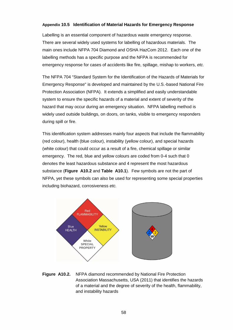
This identification system addresses mainly four aspects that include the flammability
(red colour), health (blue colour), instability (yellow colour), and special hazards
(white colour) that could occur as a result of a fire, chemical spillage or similar
emergency. The red, blue and yellow colours are coded from 0-4 such that 0
denotes the least hazardous substance and 4 represent the most hazardous
substance (Figure A10.2 and Table A10.1). Few symbols are not the part of
NFPA, yet these symbols can also be used for representing some special properties
including biohazard, corrosiveness etc.
Figure A10.2. NFPA diamond recommended by National Fire Protection
Association Massachusetts, USA (2011) that identifies the hazards of a material and the degree of severity of the health, flammability, and instability hazards
White SPECIAL
PROPERTY
59
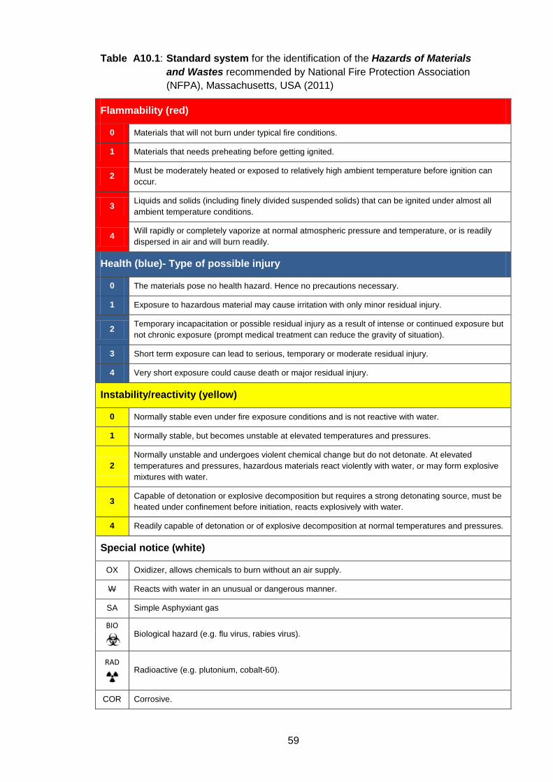
Table A10.1: Standard system for the identification of the Hazards of Materials and Wastes recommended by National Fire Protection Association (NFPA), Massachusetts, USA (2011)
Flammability (red)
0 Materials that will not burn under typical fire conditions.
1 Materials that needs preheating before getting ignited.
2 Must be moderately heated or exposed to relatively high ambient temperature before ignition can occur.
3 Liquids and solids (including finely divided suspended solids) that can be ignited under almost all ambient temperature conditions.
4 Will rapidly or completely vaporize at normal atmospheric pressure and temperature, or is readily dispersed in air and will burn readily.
Health (blue)- Type of possible injury
0 The materials pose no health hazard. Hence no precautions necessary.
1 Exposure to hazardous material may cause irritation with only minor residual injury.
2 Temporary incapacitation or possible residual injury as a result of intense or continued exposure but not chronic exposure (prompt medical treatment can reduce the gravity of situation).
3 Short term exposure can lead to serious, temporary or moderate residual injury.
4 Very short exposure could cause death or major residual injury.
Instability/reactivity (yellow)
0 Normally stable even under fire exposure conditions and is not reactive with water.
1 Normally stable, but becomes unstable at elevated temperatures and pressures.
2 Normally unstable and undergoes violent chemical change but do not detonate. At elevated temperatures and pressures, hazardous materials react violently with water, or may form explosive mixtures with water.
3 Capable of detonation or explosive decomposition but requires a strong detonating source, must be heated under confinement before initiation, reacts explosively with water.
4 Readily capable of detonation or of explosive decomposition at normal temperatures and pressures.
Special notice (white)
OX Oxidizer, allows chemicals to burn without an air supply.
W Reacts with water in an unusual or dangerous manner.
SA Simple Asphyxiant gas
BIO Biological hazard (e.g. flu virus, rabies virus).
RAD
Radioactive (e.g. plutonium, cobalt-60).
COR Corrosive.
60
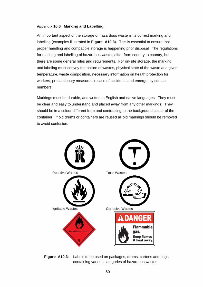
Appendix 10.6 Marking and Labelling
An important aspect of the storage of hazardous waste is its correct marking and
labelling (examples illustrated in Figure A10.3). This is essential to ensure that
proper handling and compatible storage is happening prior disposal. The regulations
for marking and labelling of hazardous wastes differ from country to country, but
there are some general rules and requirements. For on-site storage, the marking
and labeling must convey the nature of wastes, physical state of the waste at a given
temperature, waste composition, necessary information on health protection for
workers, precautionary measures in case of accidents and emergency contact
numbers.
Markings must be durable, and written in English and native languages. They must
be clear and easy to understand and placed away from any other markings. They
should be in a colour different from and contrasting to the background colour of the
container. If old drums or containers are reused all old markings should be removed
to avoid confusion.
Figure A10.3: Labels to be used on packages, drums, cartons and bags containing various categories of hazardous wastes
Reactive Wastes Toxic Wastes
Ignitable Wastes Corrosive Wastes
61
All drums, containers and tanks must be clearly labelled with the waste type and
hazard posed (see Figure A10.3). Labels should be made of good quality, durable
materials which will not be affected by weather. They should not be easily
removable. They must be legible and recognizable in daytime and at night.
Appendix 10.7 Measures for Management of Spilled and Leaked Wastes
There shall be a proper spillage control system installed in the storage shed. The
workers should be trained about the precautionary measures for handling and storing
wastes in the sheds. A proper spillage control system should also be made
available. The major specifications are listed below:
• The storage areas should be inspected daily for detecting any signs of leaks or
deterioration. Leaking or deteriorated containers should be removed and ensured
that such contents are transferred to a sound container.
• In case of spills/leaks dry adsorbents/cotton should be used for cleaning instead of
water. Adsorbing agents should always be present to clean up spills immediately.
• Proper slope with collection pits should be provided in the storage area so as to
collect the spills/leakages.
• Storage areas should be provided with adequate number of spill kits at suitable
locations. The spill kits should be provided with compatible sorbent material in
adequate quantity.
Appendix 10.8 Occupational Safety and Sanitation
• Facilities for sanitation and disaster preparation: It is recommended that
appropriate changing rooms and sanitary and washing facilities should be
provided adjoining the storage facility for the benefit of personnel coming in
contact with hazardous materials and wastes. Sanitary and washing facilities
should be conveniently accessible and situated so that they are not at risk of
contamination from the workplace. Appropriate and separate changing rooms and
sanitary and washing facilities should be provided for the exclusive use of workers
handling wastes like asbestos. It is also recommended that the industrial facility
should designate separate and uncontaminated areas for workers to use for
eating, drinking and for resting during breaks.
• Inspection: The procedures for inspection and maintenance of equipment, and
the requirements for third-party inspections and decontamination should be
properly laid down. These activities and the result of the inspections should be
62
recorded. The industrial facility should ensure that the quantity and the
deployment of tools and equipment are suitable for the corresponding industrial
activities.
• Personal protective equipment: Information on procedures and equipment used
for the protection of employees from various risks associated with industrial
processes should be provided. Respiratory protection and hearing conservation
programmes should be developed for all employees who could be exposed to
excessive levels of contaminants. The personal protective equipment (PPE)
includes safety shoes, helmets, various types of gloves, aprons, dust respirators,
ear plugs, goggles etc. taking employee strength into consideration and distributed
to facility employees and contractor's employees.
• Other safety requirements: The shed must have adequate fire-fighting
equipment that includes fire hydrants, sprinklers, foams etc. Capacity building
programmes for workers must be initiated to create awareness along with regular
medical checkups to understand the health condition of the workers. A competent
agency may be appointed for the handling of hazardous wastes, especially
asbestos, to reduce occupational and environmental risks. There should be
adequate insurance coverage including general liability.
• Storage and labelling after removal: The industrial facility’s procedures should
describe how all wastes generated from various industrial processes should be
kept separate from recyclable materials and equipment, clearly labeled for
identification and stored in appropriate conditions either temporarily or for a longer
term. These should describe how the industrial facility will avoid waste being
mixed or contaminated in a way that interferes with subsequent handling, storage,
treatment, recycling or disposal.
• Prohibition on smoking: Smoking and naked flames must be prohibited in the
and around the storage yards where flammables and combustibles are kept. “No
smoking” signboards have to prominently displayed in the yard.
63
References and Bibliography
Arceivala, S. J. and Asolekar, S. R. (2006). “Wastewater Treatment for Pollution Control” (3rd
Edition, 11th Reprint), McGraw Hill Education (India) Pvt. Ltd., New Delhi
Arceivala, S. J. and Asolekar, S. R. (2012). “Environmental Studies: A Practitioner’s
Approach”, McGraw Hill Education (India) Pvt. Ltd., New Delhi
Asolekar S. R., Key note address entitled Zero Liquid Discharge in the Conference organized
by Indian Environmental Association during Jan 22nd and 23rd, 2016 at Mumbai, India.
Asolekar, S. R. (2006). Status of Management of Solid Hazardous Wastes Generated during
Dismantling of Obsolete Ships in India, presented at the First International Conference
on Dismantling of Obsolete Vessels, Glasgow, Scotland, UK, September 11-12.
Asolekar, S. R. (2012) Greening of ship recycling in India upgrading facilities in Alang.
Proceedings of 7th Annual Ship Recycling Conference organized by Informa Maritime
Events and Lloyd's List, held in London, UK, December 10-13.
Asolekar, S. R. and Gopichandran, R. (2005). “Preventive Environmental Management – An
Indian Perspective”, Foundation Books Pvt. Ltd., New Delhi (the Indian associate of
Cambridge University Press, UK)
Asolekar, S. R. and Hiremath, A. M. (2013). India’s Contribution in Preventive Environmental
Management of Obsolete Vessels. Indian Ports and Infrastructure Magazine, August,
2012, 5-7.
Asolekar, S. R., and Hiremath, A. M. (2013) India’s Contribution in Preventive Environmental
Management of Obsolete Vessels. Indian Ports and Infrastructure Magazine, 8, 5-7.
Asolekar, S. R., Gopichandran, R., Hiremath, A. M. and Kumar D. (2015). “Green chemistry
and ecological engineering as a framework for sustainable development” in an
integrated approach to environmental management (eds D. Sarkar, R. Datta, A.
Mukherjee and R. Hannigan), John Wiley & Sons, Inc, Hoboken, NJ, USA. (DOI:
10.1002/9781118744406.ch4)
Asolekar, S. R., Hiremath, A. M. and Vasant S. C. (2013) Carbon Foot Printing of Ports in
Mumbai. Indian Ports and Infrastructure Magazine, February, 2013, 19-21.
CCS101 (2014) The Carbon Capture and Storage Information Source, Greenhouse Gas
Abatement in Energy Intensive Industries. Available at
<http//ccs101.ca/assets/Documents/ghgt5.pdf> (Last accessed on 20 May, 2014).
Central Electricity Authority, Government of India (2013) CO2 baseline database for the Indian
power sector, user guide, version 8.0, January 2013.
Chowhan, M. V. S., Hiremath, A. M. and Asolekar, S. R. (2013) Carbon Foot printing of
64
Container Terminal Ports in Mumbai. In the Proceedings of International Conference on
Impact of climate change on Food, Energy and Environment (ICCFEE-2013). Elsevier
Publication ISBN - 978-93-510710-1-3.
CPCB, 1999. Guidelines for setting up of operating facility: Hazardous Waste Management
(HAZWAMS/11/1998-99), Government of India.
CPCB, 2010a. Protocol for Performance Evaluation and Monitoring of the Common
Hazardous Waste Treatment Storage and Disposal Facilities including Common
Hazardous Waste Incinerators, Government of India.
CPCB, 2010b. Guidelines on Co-processing in Cement/ Power/ Steel Industry, Government
of India.
Deshpande P. C., Kalbar, P. P., Tilwankar, A. K., Asolekar, S. R. (2013) A Novel methodology
to develop emission factors for pollutants from ship recycling yards based on input
output studies. Journal of Cleaner Production, 59, 251-259.
Deshpande P. C., Tilwankar A. K., and Asolekar S. R. (2012) A Novel approach to estimating
potential maximum heavy metal exposure to ship recycling yard workers in Alang,
India. Science of The Total Environment, 438, 304-311.
Deshpande, P. C., Hiremath, A. M., Kalbar, P. P. and Asolekar, S. R. (2014) Towards Green
Ship Dismantling Scientific Assessment of Health, Safety and Environment Agenda. In
the Proceedings of the International Conference on Ship Recycling SHIPREC2013 held
in Malmö, Sweden, Pages 233-242,WMU Publications 2014,ISBN 978-91-977254-8-4
(Won best paper award).
Directives 2008/98/EC of The European Parliament and of The Council of 19 November 2008
on waste and repealing certain Directives.
Dutta, S.K., Upadhyay, V.P. and Sridharan, U., 2006. Environmental management of
Industrial Hazardous Wastes in India. Journal of Environmental Science and
Engineering, 48(2), pp.143.
EPA-712-C-96-129 Fish BCF, Ecological effects test guidelines, United States Environmental
Protection Agency.
EU Ship Recycling Regulation (2013) European Union Ship Recycling Regulation adopted by
the European Council and published in the Official Journal of the EU to become legally
binding. The Regulation entered into force on 30 December 2013. Available at
<http://maritimesun.com/news/ship-recycling-new-eu-regulation>.
Garmer, K., Shastrum, H., Hiremath, A. M., Tilwankar, A. K. and Asolekar S. R. (2015)
Identification and Assessment of Risks in Ship Dismantling Industry: A Three-step
Method Approch. Journal of Safety Science, Volume 76, Pages 175-189 [Elsevier
Publication; IF 2.21/2015].
65
Garmer, K., Sjöström, H., Hiremath, A.M., Tilwankar, A. K., Kinigalakis, G. and Asolekar, S.
R. (2015). Development and validation of Three-Step Risk Assessment Method for
Ship Recycling Sector. Safety Science 76, 175–189. [IF = 2.21].
Gopichandran, R., Asolekar, S. R., Jani, O., Kumar D. and Hiremath, A. M. (2015). “Green
energy and climate change” in “An integrated approach to environmental management”
(eds D. Sarkar, R. Datta, A. Mukherjee and R. Hannigan), John Wiley & Sons, Inc,
Hoboken, NJ, USA. (DOI: 10.1002/9781118744406.ch5)
Hazardous and Other Wastes (Management and Transboundary movement) Rules, 2016.
Ministry of Environment, Forest and Climate Change, Government of India.
Hiremath A. M. and Asolekar S. R. (2010) Environmental Risk Assessment. Poster
Presentation at Ninth National Conference of Indian Environmental Association in IIT
Bombay.
Hiremath A. M. and Asolekar S. R. (2012) Ship Recycling Yards Modernizations and Up
gradation. Podium presentation at the First National Conference on Ship recycling on
the Indian sub-continent organised by Hinode events and services private limited at
Hotel Vivanta – by Taj President, Cuffe Parade, Mumbai, India.
Hiremath, A. M. and Asolekar, S. R. (2012) Ballast Water Management Current Status and
Future Challenges An Engineering Aspect. Presented in the National Conference on
Water Quality Management organized by Department of Civil Engineering, Malaviya
National Institute of Technology Jaipur, India.
Hiremath, A. M., Chowhan, M. V. S. and Asolekar, S. R. (2013) Realistic Expectations of the
Carbon Footprint of Ports in India. Podium presentation at the First international
Conference on Green Port South Asia organized by Mercator Media Private Limited at
Trident Nariman Point Hotel, Mumbai, India.
Hiremath, A. M., Kholgade, N, P., and Asolekar, S. R. (2015) Heavy Metals Exposure to
Workers in Ship Recycling Yards through Inhalation and Ingestion (manuscript to be
communicated in Science of Total Environment) [Elsevier Publication; IF 4.09/2015].
Hiremath, A. M., Pandey, S. K. and Asolekar, S. R. (2016) Development of Ship-Specific
Dismantling Plan to improve Health Safety and Environment in Ship Yards Journal of
Cleaner Production, 116, 279-298. [Elsevier Publication; IF 3.84/2015].
Hiremath, A. M., Pandey, S. K., Kumar, D. and Asolekar, S. R (2014) Ecological Engineering,
Industrial Ecology and Eco-Industrial Networking Aspects of Ship Recycling Sector in
India. APCBEE Procedia, Volume 10, Pages 159-163.
Hiremath, A. M., Pandey, S. K., Salve, A. B. and Asolekar, S. R. (2014) Integrated Risk
Assessment Framework for Ship Recycling Sector. In the Proceedings of the
International Conference on Ship Recycling SHIPREC2013 held in Malmö, Sweden,
Pages 41-54, WMU Publications 2014, ISBN 978-91-977254-8-4.
66
Hiremath, A. M., Raj, R. and Asolekar, S. R. (2015) Minimization of Carbon foot priniting of
Ship Recycling through Implication of Cleaner Technologies (revised manuscript under
review in Journal of Cleaner Production) [Elsevier Publication; IF 3.84/2015].
Hiremath, A. M., Salve, A. B., Pandey, S. K. and Asolekar, S. R. (2014) Comprehensive
Account on Dismantling & Recycling of an Oil Tanker Ship in Alang, India. In the
Proceedings of the International Conference on Ship Recycling SHIPREC2013 held in
Malmö, Sweden, Pages 175-188, WMU Publications 2014, ISBN 978-91-977254-8-4.
Hiremath, A. M., Tilwankar, A. K. and Asolekar, S. R. (2011) Green Ship Recycling
Challenges and Way Forward. Podium presentation at Third National Conference on
Ports and Infrastructure organised by Saket Projects Ltd. in Ahmedabad, Gujarat,
India.
Hiremath, A. M., Tilwankar, A. K. and Asolekar, S. R. (2015) Significant Steps in Ship
Dismantling Vis-a-vis Wastes Generated in a Clusater of Yards in Alang A Case Study.
Journal of Cleaner Production, Volume 87, Pages 520-532. [Elsevier Publication; IF
3.84/2015].
Hiremath, A. M., Tilwankar, A. K. and Asolekar, S. R. (2015). Significant Steps in Ship
Dismantling vis-a-vis Wastes Generated in a Clusater of Yards in Alang A Case Study.
Journal of Cleaner Production, 87, 520-532. [IF = 3.84].
ICRA Rating Feature, (2012) Ship Breaking Industry Key Trends and Credit Implications.
Available at <www.icra.in>.
IEA (2012) International Energy Agency CO2 emissions from fuel combustion highlights, 2012
Edition. Available at <http//www.iea.org/co2highlights/co2highlights.pdf> (Last
accessed on 3 June, 2014).
ILO (2004) Safety and health in ship breaking: Guidelines for Asian countries and Turkey,
Interregional Tripartite Meeting of Experts on Safety and Health in Shipbreaking for
Selected Asian Countries and Turkey, Bangkok”, ISBN 92-2-115289-8
<http://www.ilo.org/public/english/standards/relm/gb/docs/gb289/pdf/meshs-1.pdf>.
IMO (2013) International Maritime Organization Report on International Shipping Facts and
Figures – Information Resources on Trade Safety, Security, Environment. Available at
<http//www.imo.org/KnowledgeCentre/ShipsAndShippingFactsAndFigures/
Statisticalresources/Documents/December%202011%20update%20to%20July%20201
1%20version%20of%20International%20Shipping%20Facts%20and%20Figures.pdf>
(Last accessed on 26 May, 2014).
IMO (2015) Recycling of Ships: The development of the Hong Kong Convention. Available at
<http://www.imo.org/en/OurWork/Environment/ShipRecycling/Pages/Default.aspx>.
67
Indian Factory Act, (1948) Available at <http//www.delhi.gov.in/wps/wcm/connect/doit_labour
/Labour/Home/Acts+Implemented/Details+of+the+Acts+Implemented/The+Factories+A
ct,+1948/The+Second+Schedule> (Last accessed on 27 February, 2014).
Inventory Guidelines, (2009) Guidelines for the development of the inventory of hazardous
materials”, Resolution MEPC.179(59), Adopted on 17 July, 2009. Available at
<http://www.imo.org/OurWork/Environment/ShipRecycling/Documents/RESOLUTION%
20MEPC.179(59)%20Inventory%20guidelines.pdf>.
IPCC (2006) Intergovernmental Panel for Climate Change IPCC Guidelines for National
Greenhouse Gas Inventories, Prepared by the National Greenhouse Gas Inventories
Programme, Eggleston H.S., Buendia L., Miwa K., Ngara T. and Tanabe K. (eds).
Published IGES, Japan.
IPCC (2007) Intergovernmental panel for climate change, fourth assessment report: climate
change 2007, Available at <http://www.ipcc.ch/pdf/assessment
report/ar4/syr/ar4_syr.pdf> (Last accessed on 3 June, 2014).
IRIS (2013) Integrated Risk Information System U.S. Environmental Protection Agency,
Available at <http//www.epa.gov/IRIS/>.
ISO (2012) International Organization for Standardization (n.d). Safety aspects. Guidelines for
their inclusion in standards, ISO/IEC Guide, 51.
ISO (2012) International Organization for Standardization (n.d). Safety aspects. Guidelines for
their inclusion in standards, ISO/IEC Guide, 51.
ISO (2013) International Standardization Organization ISO 140672013 Available at
<https//www.iso.org/obp/ui/#isostdisots14067ed-1v1en> (Last accessed on 3 June,
2014)
ISO (2013) International Standardization Organization ISO 140672013 Available at
<https//www.iso.org/obp/ui/#isostdisots14067ed-1v1en> (Last accessed on 3 June,
2014)
ISO 14040 and 14044 (2006) Life cycle assessment. Available at
<http://www.iso.org/iso/catalogue_detail?csnumber=38498>.
ISO 14040 and 14044 (2006) Life cycle assessment. Available at
<http://www.iso.org/iso/catalogue_detail?csnumber=38498>.
LaGrega, M.D., Buckingham, P.L. and Evans, J.C., 2010. Hazardous waste management.
Waveland Press
Kumar S., Pandey S. K., Sawaikar U. and Asolekar S. R., Poster presentation on
"Technology for Greening of Ship: Onboard Modular Bilge Water Purification System" "
in SIG Environment Global Business Forum, organized by IIT Bombay Alumni
Association at Taleigao, Goa during Oct 16th and 18th, 2015.
68
Mahindrakar A. B., Das S. K., Asolekar S. R., and Kura B. (2008) Environmental Issues in the
Ship breaking Industry in India. In the proceedings of the A&WMA’s Annual
Conference, Portland, Oregon, USA, June 24-26.
Mahindrakar, A. B. and Asolekar, S. R. (2006) Characterisation, treatment and disposal of
paint chip wastes generated in Indian ship breaking industry. Proceedings of
International Conference on Dismantling of obsolete vessels, University of Glasgow.
MARPOL (1974) Marine Pollution, International Convention for the Prevention of Pollution
from Ships. Available at
<http://www.imo.org/en/About/Conventions/ListOfConventions/Pages/International-
Convention-for-the-Prevention-of-Pollution-from-Ships-(MARPOL).aspx>.
Mikelis, N. (2013) Ship Recycling Markets and the Impact of the Hong Kong Convention.
Proceedings of the International Conference on Ship Recycling (SHIPREC 2013),
World Maritime University, Malmo.
National Fire Protection Association, 2011. NFPA 704, Standard System for the Identification
of the Hazards of Materials for Emergency Response. National Fire Protection
Association, Quincy, Massachusetts, USA
OSHA (2001) Occupational Safety and health administration factsheet ship breaking.
Occupational Safety and Health Administration, U.S. Department of Labour.
Pandey S. K., Rao B. and Asolekar S. R., Poster presentation on "Remediation of Beaches,
Soils and Sediments" for a Smart City in SIG Environment Global Business Forum,
organized by IIT Bombay Alumni Association at Taleigao, Goa during Oct 16th and 18th,
2015.
Pandey, S. K., Hiremath, A. M., Salve, A. B. and Asolekar, S. R. (2014) What Difference Can
Hong-Kong Convention Make to Ship Recycling in India? In the Proceedings of the
International Conference on Ship Recycling SHIPREC2013 held in Malmö, Sweden,
Pages 79-94, WMU Publications 2014, ISBN 978-91-977254-8-4.
Singh R., Vivek J. M., Rao B. and Asolekar S. R. (2016). Significance of Presence of
Asbestos in Construction and Demolition Wastes in India. Presented paper in
International Conference on Waste Management (Recycle 2016) at IIT Guwahati,
Assam during Apr 1st and 2nd, 2016.
Sutar R. S., Motghare V. M., Kollur S. C., Parikh Y. and Asolekar S. R. (2015). Would the
persistence of micropollutants compromise reuse options for the treated wastewater?
Presented paper in the National Conference on Environmental Monitoring, Assessment
and Pollution Control i.e. EMAPCO 2015 organized by the SIES Educational Campus
at Navi Mumbai, Maharashtra during Dec 10th and 11th, 2015.
The Factories Act, 1948. Directorate General Factory Advice Service & Labour Institutes,
Government of India.
69
The Motor Vehicles Act, 1988. Ministry of Road Transport and Highways, Government of
India.
Tilwankar, A. K., Hiremath, A. M. and Asolekar, S. R. (2011) Recommendations for Health,
Safety and Environmental Quality (HSEQ) Improvement in Ship Recycling Industry.
Podium presentation at the 10th Technical Meeting and Workshop on Green Ship
Recycling organised by the University of Glasgow and Strathclyde in London, UK.
UNEP, 1993. Storage of hazardous materials-A technical guide for safe warehousing of
hazardous materials, United Nations Environmental Programme, Industry and
Environment Programme Activity Centre (IE/PAC), Paris, France
UNEP and ISWA., 2002. Training Resource Pack for Hazardous Waste Management in
Developing Economies.
UNEP, 2003. Basel Convention Technical Guidelines on Incineration on Land. Secretariat of
Basel Convention, UNEP, Geneva.
USEPA 40 CFR §264 and §265, 2014. “Standards for Owners and Operators of Hazardous
Waste Treatment, Storage and Disposal Facilities”. Code of Federal Regulations,
Office of the Federal Register.
USEPA 40 CFR §264 -E and §265-E, 2014. “Subpart E—Manifest System, Recordkeeping,
and Reporting” Code of Federal Regulations, Office of the Federal Register.
Vivek J. M., Pandey S. K., Joshi R. P. and Asolekar S. R., Poster presentation on "Mobile
Wastewater Treatment Facility" " in SIG Environment Global Business Forum,
organized by IIT Bombay Alumni Association at Taleigao, Goa during Oct 16th and 18th,
2015.
Vivek J. M., Singh R., Sutar R. S. and Asolekar S. R. (2016). Characterization and Disposal of
Ashes from Biomedical Waste Incinerator. Presented paper in International Conference
on Waste Management (Recycle 2016) at IIT Guwahati, Assam during Apr 1st and 2nd,
2016.
---x--X—0O0---X--x---