When an IDS is deployed, you must tune its implementation to increase its effectiveness and remove “false positives.”
False-positives are defined as alarms caused by legitimate traffic or activity. False negatives are attacks that the IDS system
fails to see. When the IDS is tuned, you can configure it more specifically as to its threat-mitigation role. As mentioned above,
you should configure HIDS to stop most valid threats at the host level because it is well prepared to determine that certain
activity is, indeed, a threat.
When deciding on mitigation roles for NIDS, you have two primary options. Remember that the first step prior to
implementing any threat-response option is to adequately tune NIDS to ensure that any percieved threat is legitimate.
The first option-and potentially the most damaging if improperly deployed-is to “shun” traffic through the addition of access
control filters on routers and firewalls. When a NIDS detects an attack from a particular host over a particular protocol, it
can block that host from coming into the network for a predetermined amount of time. Although on the surface this might
seem like a great aid to a security administrator, in reality it must be very carefully implemented, if at all. The first problem
is that of spoofed addresses. If traffic that matches an attack is seen by the NIDS, and that particular alarm triggers a shun
situation, the NIDS will deploy the access list to the device. However, if the attack that caused the alarm used a spoofed
address, the NIDS has now locked out an address that never initiated an attack. If the IP address that the hacker used happens
to be the IP address of a major ISP’s outbound HTTP proxy server, a huge number of users could be locked out. This by itself
could be an interesting DoS threat in the hands of a creative hacker.
To mitigate the risks of shunning, you should generally use it only on TCP traffic, which is much more difficult to successfully
spoof than UDP. Use it only in cases where the threat is real and the chance that the attack is a false positive is very low. Also
consider setting the shun length very short. This setup will block the user long enough to allow the administrator to decide
what permanent action (if any) he/she wants to take against that IP address. However, in the interior of a network, many
more options exist. With effectively deployed RFC 2827 filtering, spoofed traffic should be very limited. Also, because
customers are not generally on the internal network, you can take a more restrictive stance against internally originated
attack attempts. Another reason for this is that internal networks do not often have the same level of stateful filtering that
edge connections possess. As such, IDS needs to be more heavily relied upon than in the external environment.
The second option for NIDS mitigation is the use of TCP resets. As the name implies, TCP resets operate only on TCP traffic
and terminate an active attack by sending TCP reset messages to the attacking and attacked host. Because TCP traffic is more
difficult to spoof, you should consider using TCP resets more often than shunning. Keep in mind that TCP resets in a switched
environment are more challenging than when a standard hub is used, because all ports don’t see all traffic without the use of
a Switched Port Analyzer (SPAN) or mirror port. Make sure this mirror port supports bidirectional traffic flows and can
have SPAN port MAC learning disabled.
Both of these mitigation options require 24x7 staffing to watch the IDS consoles. Because IT staff are often overworked,
(particularly in smaller organizations), consider outsourcing your IDS management to a third party.
From a performance standpoint, NIDS observes packets on the wire. If packets are sent faster than the NIDS can process
them, there is no degradation to the network because the NIDS does not sit directly in the flows of data. However, the NIDS
will lose effectiveness and packets could be missed, causing both false negatives and false positives. Be sure to avoid exceeding
the capabilities of IDS so that you can get their benefit. From a routing standpoint, IDS, like many state-aware engines, does
not operate properly in an asymmetrically routed environment. Packets sent out from one set of routers and switches and
returning through another will cause the IDS systems to see only half the traffic, causing false positives and false negatives.
Secure Management and Reporting“If you’re going to log it, read it.” This proposition is so simple that almost everyone familiar with network security has said
it at least once. Yet logging and reading information from many devices can be very challenging. Which logs are most
important? How do I separate important messages from mere notifications? How do I ensure that logs are not tampered with
in transit? How do I ensure that my time stamps match each other when multiple devices report the same alarm? What
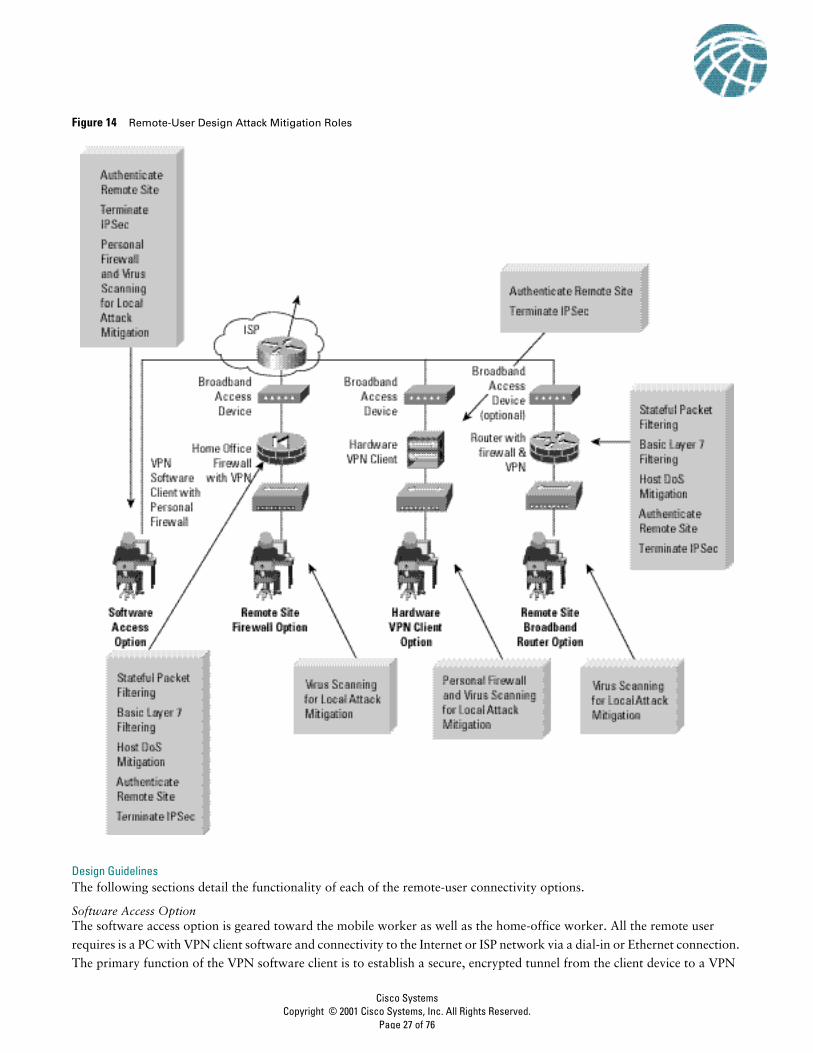
headend device. Access and authorization to the network are controlled from the headquarters location when filtering takes
place on the firewall and on the client itself if access rights are pushed down via policy. The remote user is first authenticated,
and then receives IP parameters such as a virtual IP address, which is used for all VPN traffic, and the location of name servers
(DNS and Windows Internet Name Service [WINS]). Split tunneling can also be enabled or disabled via the central site. For
the SAFE design, split tunneling was disabled, making it necessary for all remote users to access the Internet via the corporate
connection when they have a VPN tunnel established. Because the remote user may not always want the VPN tunnel
established when connected to the Internet or ISP network, personal firewall software is recommended to mitigate against
unauthorized access to the PC. Virus-scanning software is also recommended to mitigate against viruses and Trojan horse
programs infecting the PC.
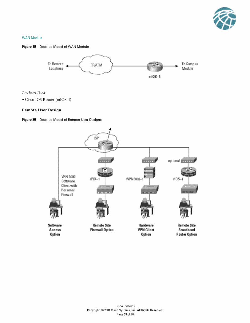
Remote-Site Firewall OptionThe remote-site firewall option is geared toward the home-office worker, or potentially a very small branch office. With this
option, it is expected that the remote site has some form of broadband access available from a service provider. The firewall
is installed behind the DSL or cable modem.
The primary function of the firewall is to establish the secure, encrypted tunnel between itself and a VPN headend device, as
well as providing connection-state enforcement and detailed filtering for sessions initiated through it. Individual PCs on the
remote-site network do not need VPN client software to access corporate resources. Additionally, because the stateful
firewall protects access to the Internet, personal firewall software isn’t necessarily required on the individual PCs. However,
if the network administrator wants an additional level of security, personal firewall software can also be implemented on
remote-site PCs. This setup may be useful if the home worker also travels and connects to the Internet directly over some
public network. Because we have a stateful firewall protecting the hosts, the remote site can have direct access to the Internet,
rather than passing all traffic back through the corporate headquarters. Unless NAT is used when communicating with the
headquarters, the IP addresses of the remote-site devices should be assigned in such a manner as to not overlap addressing
space in the headquarters location or another remote site. Remote-site devices that require direct access to the Internet will
require address translation to a registered address. This address translation can be achieved by translating all Internet-bound
sessions to the public IP address of the firewall itself.
Access and authorization to the corporate network and the Internet are controlled by the configuration of both the
remote-site firewall and the VPN headend device. Configuration and security management of the remote-site firewall can be
achieved via an IPSec tunnel from the public side of the firewall back to the corporate headquarters. This setup ensures that
the remote-site user(s) is not required to perform any configuration changes on the home-office firewall. Authentication
should be set up on the firewall to prevent a local user from inadvertently modifying his/her firewall configuration and
thereby compromise the security policy of that device. Individual users at the remote site who access the corporate network
are not authenticated with this option. Instead, the remote-site firewall and VPN headend utilize device authentication.
Virus-scanning software is still recommended to mitigate against viruses and Trojan horse programs infecting individual PCs
at the remote site-just like all the PCs in the entire corporation.
Hardware VPN Client OptionThe hardware VPN client option is identical to the remote-site firewall option except that the hardware VPN client does not
have a resident stateful firewall. This setup requires use of a personal firewall on the individual hosts, particularly when split
tunneling is enabled. Without the personal firewall, the security of the individual hosts behind the VPN device is dependant
upon the attacker being unable to circumvent Network Address Translation (NAT). This is because when split tunneling is
enabled, connections to the Internet pass through a simple many-to-one NAT translation and do not undergo any filtering
at Layer 4 and above. With split tunneling disabled, all access to the Internet must be through the corporate headquarters.
This setup partially mitigates the requirement for personal firewalls on the end systems.
A reference implementation exists to validate the functionality described in this document. This appendix details the
configurations of the specific devices within each module as well as the overall guidelines for general device configuration.
The following are configuration snapshots from the live devices in the lab. The authors do not recommend applying these
configurations directly to a production network.
Overall Guidelines
The sample commands presented in this section correspond in part to the SAFE axioms presented earlier in this document.
RoutersThe following are sample commands that enable most of the basic configuration options present on most routers in the lab.
! Turn off unnecessary services
!no ip domain-lookupno cdp runno ip http serverno ip source-routeno service fingerno ip bootp serverno service udp-small-serversno service tcp-small-servers
!access-list 98 permit host 10.3.8.253access-list 98 permit host 10.3.8.254access-list 98 deny any log!line vty 0 4 access-class 99 in login authentication default password 0 X)[^j+#T98 exec-timeout 2 0 transport input ssh transport output noneline con 0 login authentication no_tacacs password 0 X)[^j+#T98 exec-timeout 2 0 transport input noneline aux 0 transport input none password 0 X)[^j+#T98 no exec!banner motd #
This is a private system operated for and by Cisco VSEC BU. Authorization from Cisco VSEC management is required to use this system. Use by unauthorized persons is prohibited.
#
! Turn on NTP with authentication and access control
set logout 2set ip permit enable telnetset ip permit 10.3.8.253 255.255.255.255 telnetset ip permit 10.3.8.254 255.255.255.255 telnet
HostsAs discussed in the Axioms sections, the host operating systems and applications ran HIDS and had the latest patches and
fixes applied. The HIDS application used in the lab is the Entercept application from Entercept Security Technologies. More
information is available at http://www.entercept.com.
Small Network Configurations
The following are configuration snapshots from the SAFE small network.
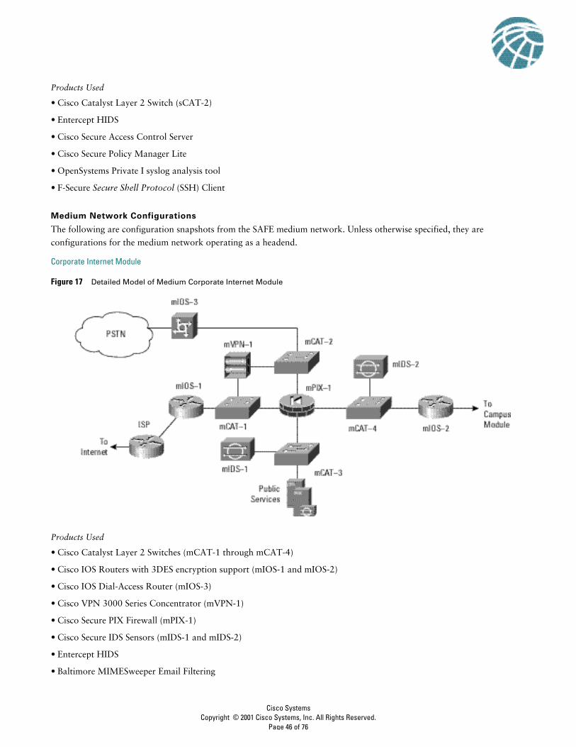
Corporate Internet Module
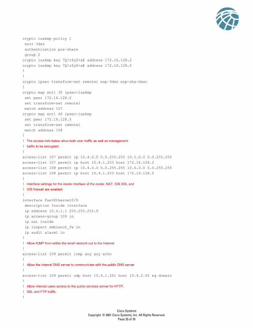
Figure 15 Detailed Model of Small Network Corporate Internet Module
Products Used
• Cisco Catalyst Layer 2 Switch (sCAT-1)
• Cisco IOS Router with Triple Data Encryption Standard (3DES) encryption support (sIOS-1)
• Cisco Secure PIX Firewall (sPIX-1)
• Entercept HIDS
sIOS-1The following configuration snapshot details the access lists on the small network edge router, controlling traffic inbound
and outbound to the small network. Note: The small router configurations do not show the remote access VPN
configurations; this functionality will be available in Cisco IOS Software soon.
! Basic IOS IDS configuration using syslog for reporting
!ip audit attack action alarm drop resetip audit notify logip audit name alarm1 info action alarmip audit name alarm1 attack action alarm drop!! IPSec crypto configuration to remote branches of the small network
crypto isakmp policy 1 encr 3des authentication pre-share group 2crypto isakmp key 7Q!r$y$+xE address 172.16.128.2 crypto isakmp key 7Q!r$y$+xE address 172.16.128.5 !!crypto ipsec transform-set remote1 esp-3des esp-sha-hmac !crypto map ent1 30 ipsec-isakmp set peer 172.16.128.2 set transform-set remote1 match address 107crypto map ent1 40 ipsec-isakmp set peer 172.16.128.5 set transform-set remote1 match address 108!! The access-lists below allow both user traffic as well as management
! traffic to be encrypted
!access-list 107 permit ip 10.4.0.0 0.0.255.255 10.5.0.0 0.0.255.255access-list 107 permit ip host 10.4.1.253 host 172.16.128.2access-list 108 permit ip 10.4.0.0 0.0.255.255 10.6.0.0 0.0.255.255access-list 108 permit ip host 10.4.1.253 host 172.16.128.5!! Interface settings for the inside interface of the router. NAT, IOS IDS, and
! IOS firewall are enabled.
!interface FastEthernet0/0 description Inside Interface ip address 10.4.1.1 255.255.255.0 ip access-group 109 in ip nat inside ip inspect smbranch_fw in ip audit alarm1 in!! Allow ICMP from within the small network out to the Internet
!access-list 109 permit icmp any any echo!! Allow the internal DNS server to communicate with the public DNS server
!access-list 109 permit udp host 10.4.1.201 host 10.4.2.50 eq domain!! Allow internal users access to the public services server for HTTP,
access-list 109 permit tcp 10.4.0.0 0.0.255.255 host 10.4.2.50 eq wwwaccess-list 109 permit tcp 10.4.0.0 0.0.255.255 host 10.4.2.50 eq 443access-list 109 permit tcp 10.4.0.0 0.0.255.255 host 10.4.2.50 eq ftp!! Allow the internal mail server to communicate with the public mail server
!access-list 109 permit tcp host 10.4.1.201 host 10.4.2.50 eq smtp!! Allow Telnet access from the management host to the sCAT-1 switch
!access-list 109 permit tcp host 10.4.1.253 host 10.4.2.4 eq telnet!! Deny all other access to the public services segment
!access-list 109 deny ip any 10.4.2.0 0.0.0.255!! Allow the sIOS-1 router and sCAT-2 switch to synchronize time
!access-list 109 permit udp host 10.4.1.4 host 10.4.1.1 eq ntp!! Allow SSH access from the management host to the sIOS-1 router
!access-list 109 permit tcp host 10.4.1.253 host 10.4.1.1 eq 22!! Allow established connections to the management host back to the sIOS-1 router
!access-list 109 permit tcp host 10.4.1.253 eq tacacs host 10.4.1.1 established!! Necessary for TFTP access from the management host to the sIOS-1 router
!access-list 109 permit udp host 10.4.1.253 gt 1023 host 10.4.1.1 gt 1023!! Block all other access to the inside interface on the sIOS-1 router from the
! internal network
!access-list 109 deny ip 10.4.0.0 0.0.255.255 host 10.4.1.1!! Block all other access to the outside interface on the sIOS-1 router from the
! internal network
!access-list 109 deny ip 10.4.0.0 0.0.255.255 host 172.16.132.2!! Allow all other internal devices access to the Internet
!access-list 109 permit ip 10.4.0.0 0.0.255.255 any!! Block and log all other traffic
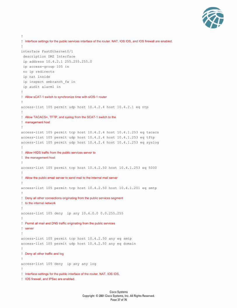
!! Interface settings for the public services interface of the router. NAT, IOS IDS, and IOS firewall are enabled.
! interface FastEthernet0/1 description DMZ Interface ip address 10.4.2.1 255.255.255.0 ip access-group 105 in no ip redirects ip nat inside ip inspect smbranch_fw in ip audit alarm1 in!! Allow sCAT-1 switch to synchronize time with sIOS-1 router
!access-list 105 permit udp host 10.4.2.4 host 10.4.2.1 eq ntp!! Allow TACACS+, TFTP, and syslog from the SCAT-1 switch to the
! management host
!access-list 105 permit tcp host 10.4.2.4 host 10.4.1.253 eq tacacsaccess-list 105 permit udp host 10.4.2.4 host 10.4.1.253 eq tftpaccess-list 105 permit udp host 10.4.2.4 host 10.4.1.253 eq syslog!! Allow HIDS traffic from the public services server to
! the management host
!access-list 105 permit tcp host 10.4.2.50 host 10.4.1.253 eq 5000!! Allow the public email server to send mail to the internal mail server
!access-list 105 permit tcp host 10.4.2.50 host 10.4.1.201 eq smtp!! Deny all other connections originating from the public services segment
! to the internal network
!access-list 105 deny ip any 10.4.0.0 0.0.255.255!! Permit all mail and DNS traffic originating from the public services
! server
!access-list 105 permit tcp host 10.4.2.50 any eq smtpaccess-list 105 permit udp host 10.4.2.50 any eq domain! ! Deny all other traffic and log
!access-list 105 deny ip any any log!! Interface settings for the public interface of the router. NAT, IOS IDS,
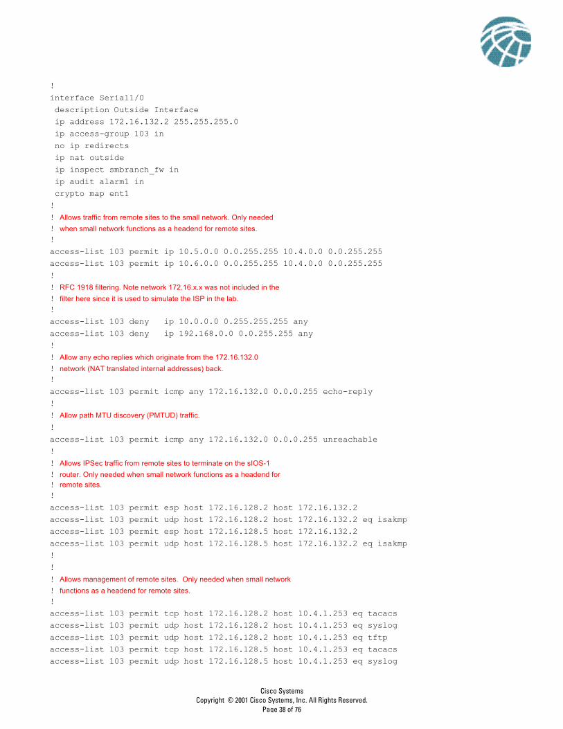
!interface Serial1/0 description Outside Interface ip address 172.16.132.2 255.255.255.0 ip access-group 103 in no ip redirects ip nat outside ip inspect smbranch_fw in ip audit alarm1 in crypto map ent1!! Allows traffic from remote sites to the small network. Only needed
! when small network functions as a headend for remote sites.!access-list 103 permit ip 10.5.0.0 0.0.255.255 10.4.0.0 0.0.255.255access-list 103 permit ip 10.6.0.0 0.0.255.255 10.4.0.0 0.0.255.255!! RFC 1918 filtering. Note network 172.16.x.x was not included in the
! filter here since it is used to simulate the ISP in the lab.!access-list 103 deny ip 10.0.0.0 0.255.255.255 anyaccess-list 103 deny ip 192.168.0.0 0.0.255.255 any! ! Allow any echo replies which originate from the 172.16.132.0
access-list 103 permit udp host 172.16.128.5 host 10.4.1.253 eq tftp!! Allow access to the public services server (via the NAT
! address of the server) for DNS, FTP, HTTP, SSL, and mail! traffic!access-list 103 permit udp any host 172.16.132.50 eq domainaccess-list 103 permit tcp any host 172.16.132.50 eq ftpaccess-list 103 permit tcp any host 172.16.132.50 eq wwwaccess-list 103 permit tcp any host 172.16.132.50 eq 443access-list 103 permit tcp any host 172.16.132.50 eq smtp! ! Deny all other traffic and log
!access-list 103 deny ip any any log
!! The following NAT configuration creates a pool of public addresses which
! are used by internal devices when they access the Internet!ip nat pool small_pool 172.16.132.101 172.16.132.150 netmask 255.255.255.0ip nat inside source route-map nat_internet pool small_pool!! Static translation of the public services server to a registered
! address accessible from the Internet!ip nat inside source static 10.4.2.50 172.16.132.50!route-map nat_internet permit 10 match ip address 104!! Do not use NAT for internal devices communicating with other network
! 10.0.0.0 devices, or for management traffic. Use NAT for all internal! devices communicating with the Internet.!access-list 104 deny ip 10.4.0.0 0.0.255.255 10.0.0.0 0.255.255.255access-list 104 deny ip host 10.4.1.253 host 172.16.128.2access-list 104 deny ip host 10.4.1.253 host 172.16.128.5access-list 104 permit ip 10.4.1.0 0.0.0.255 any!
Branch versus Headend Configuration ChangesThe following configuration snapshot details the changes necessary to make the small network a branch of a larger network
!interface Serial1/0 ip address 172.16.132.2 255.255.255.0 ip access-group 103 in crypto map ent1!! Access-list 103 would need to be modified to both the IPSec connections
! from the corporate headquarters, as well as the GRE traffic.
access-list 103 permit esp host 172.16.226.28 host 172.16.132.2access-list 103 permit udp host 172.16.226.28 host 172.16.132.2 eq isakmp!! Note that all configurations pertaining to the remote sites is removed
!access-list 103 deny ip 10.0.0.0 0.255.255.255 anyaccess-list 103 deny ip 192.168.0.0 0.0.255.255 anyaccess-list 103 permit udp any host 172.16.132.50 eq domainaccess-list 103 permit tcp any host 172.16.132.50 eq ftpaccess-list 103 permit tcp any host 172.16.132.50 eq wwwaccess-list 103 permit tcp any host 172.16.132.50 eq 443access-list 103 permit tcp any host 172.16.132.50 eq smtpaccess-list 103 permit icmp any 172.16.132.0 0.0.0.255 echo-replyaccess-list 103 permit icmp any 172.16.132.0 0.0.0.255 unreachableaccess-list 103 deny ip any any log
Minor modifications to the other access lists are required as well, but they are not shown here.
sPIX-1The following configuration snapshot details the access lists and cryptographic configuration when using the PIX Firewall
as the headend device in the small network. The PIX Firewall as configured is capable of communicating with remote sites
and terminating dial-in IPSec VPN connections.
!! Interface settings for the public interface of the firewall
!ip address outside 172.16.144.3 255.255.255.0access-group 103 in interface outside!! Allow encrypted traffic from remote sites and remote access users.
!access-list 103 permit ip 10.5.0.0 255.255.0.0 10.4.0.0 255.255.0.0 access-list 103 permit ip 10.6.0.0 255.255.0.0 10.4.0.0 255.255.0.0 access-list 103 permit ip 10.4.3.0 255.255.255.0 10.4.0.0 255.255.0.0
! RFC 1918 filtering. Note network 172.16.x.x was not included in the
! filter here since it is used to simulate the ISP in the lab.
!access-list 103 deny ip 10.0.0.0 255.0.0.0 any access-list 103 deny ip 192.168.0.0 255.255.0.0 any !! Allow access to the public services server (via the NAT
! address of the server) for DNS, FTP, HTTP, SSL, and mail! traffic!access-list 103 permit udp any host 172.16.144.50 eq domain access-list 103 permit tcp any host 172.16.144.50 eq ftp access-list 103 permit tcp any host 172.16.144.50 eq www access-list 103 permit tcp any host 172.16.144.50 eq 443 access-list 103 permit tcp any host 172.16.144.50 eq smtp!
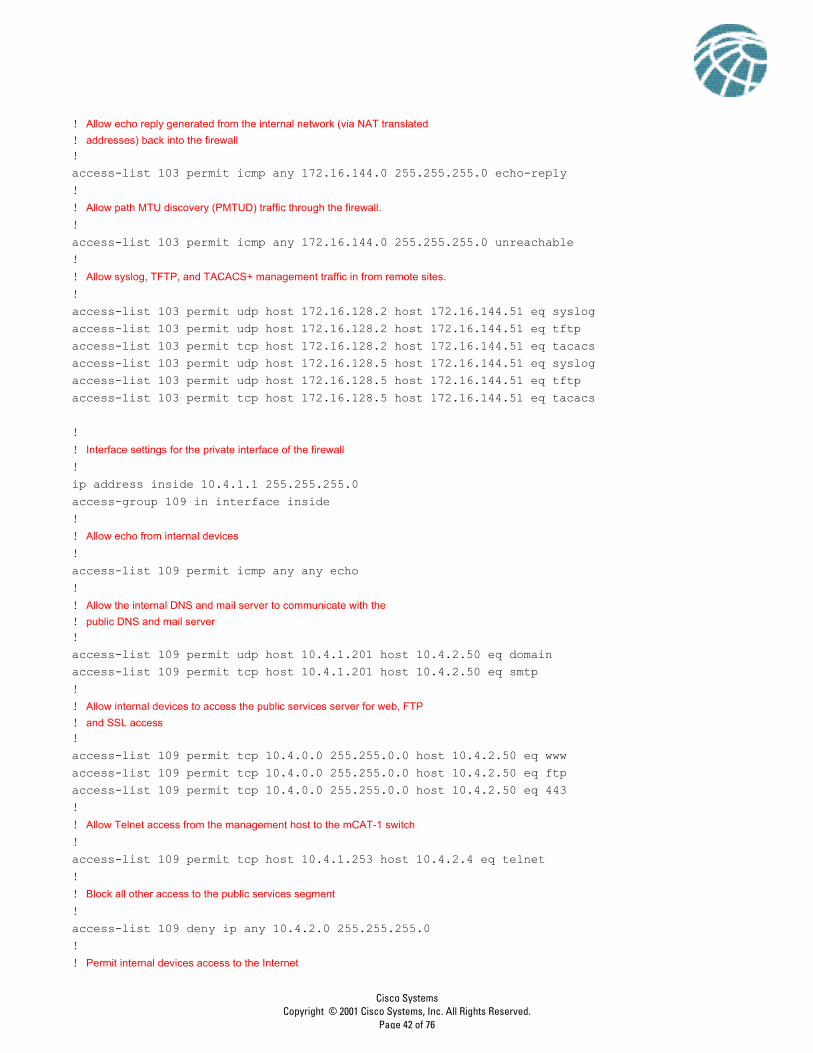
! Allow echo reply generated from the internal network (via NAT translated
! addresses) back into the firewall!access-list 103 permit icmp any 172.16.144.0 255.255.255.0 echo-reply !! Allow path MTU discovery (PMTUD) traffic through the firewall.
!access-list 103 permit icmp any 172.16.144.0 255.255.255.0 unreachable!! Allow syslog, TFTP, and TACACS+ management traffic in from remote sites.
!! Interface settings for the private interface of the firewall
!ip address inside 10.4.1.1 255.255.255.0access-group 109 in interface inside!! Allow echo from internal devices
!access-list 109 permit icmp any any echo !! Allow the internal DNS and mail server to communicate with the
! public DNS and mail server!access-list 109 permit udp host 10.4.1.201 host 10.4.2.50 eq domain access-list 109 permit tcp host 10.4.1.201 host 10.4.2.50 eq smtp !! Allow internal devices to access the public services server for web, FTP
! and SSL access!access-list 109 permit tcp 10.4.0.0 255.255.0.0 host 10.4.2.50 eq www access-list 109 permit tcp 10.4.0.0 255.255.0.0 host 10.4.2.50 eq ftp access-list 109 permit tcp 10.4.0.0 255.255.0.0 host 10.4.2.50 eq 443! ! Allow Telnet access from the management host to the mCAT-1 switch
!access-list 109 permit tcp host 10.4.1.253 host 10.4.2.4 eq telnet !! Block all other access to the public services segment
!access-list 109 deny ip any 10.4.2.0 255.255.255.0 !! Permit internal devices access to the Internet
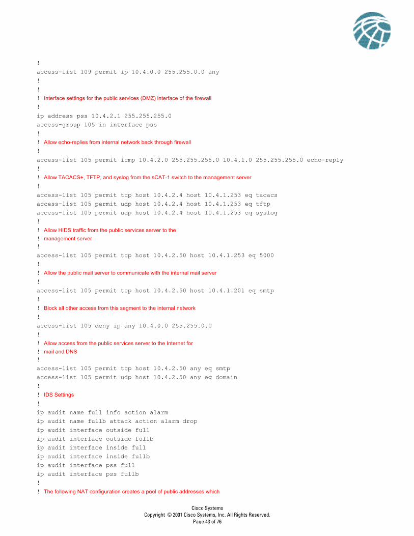
!access-list 109 permit ip 10.4.0.0 255.255.0.0 any !!! Interface settings for the public services (DMZ) interface of the firewall
!ip address pss 10.4.2.1 255.255.255.0access-group 105 in interface pss!! Allow echo-replies from internal network back through firewall
!access-list 105 permit icmp 10.4.2.0 255.255.255.0 10.4.1.0 255.255.255.0 echo-reply !! Allow TACACS+, TFTP, and syslog from the sCAT-1 switch to the management server
!access-list 105 permit tcp host 10.4.2.4 host 10.4.1.253 eq tacacs access-list 105 permit udp host 10.4.2.4 host 10.4.1.253 eq tftp access-list 105 permit udp host 10.4.2.4 host 10.4.1.253 eq syslog !! Allow HIDS traffic from the public services server to the
! management server!access-list 105 permit tcp host 10.4.2.50 host 10.4.1.253 eq 5000 !! Allow the public mail server to communicate with the internal mail server
!access-list 105 permit tcp host 10.4.2.50 host 10.4.1.201 eq smtp !! Block all other access from this segment to the internal network
!access-list 105 deny ip any 10.4.0.0 255.255.0.0 ! ! Allow access from the public services server to the Internet for
! mail and DNS!access-list 105 permit tcp host 10.4.2.50 any eq smtp access-list 105 permit udp host 10.4.2.50 any eq domain !! IDS Settings
!ip audit name full info action alarmip audit name fullb attack action alarm dropip audit interface outside fullip audit interface outside fullbip audit interface inside fullip audit interface inside fullbip audit interface pss fullip audit interface pss fullb!! The following NAT configuration creates a pool of public addresses which
! are used by internal devices when they access the Internet
!global (outside) 1 172.16.144.201-172.16.144.220!nat (inside) 0 access-list nonatnat (inside) 1 0.0.0.0 0.0.0.0 0 0nat (pss) 0 access-list nonat!! Static translation of the public services server to a registered address
!access-list nonat permit ip 10.4.0.0 255.255.0.0 10.5.0.0 255.255.0.0 access-list nonat permit ip 10.4.0.0 255.255.0.0 10.6.0.0 255.255.0.0 access-list nonat permit ip 10.4.1.0 255.255.255.0 10.4.3.0 255.255.255.0 access-list nonat permit ip 10.4.2.0 255.255.255.0 10.4.3.0 255.255.255.0 access-list nonat permit ip 10.4.1.0 255.255.255.0 10.4.2.0 255.255.255.0 !! The following crypto settings are used when the firewall terminates VPN connections from the remote sites
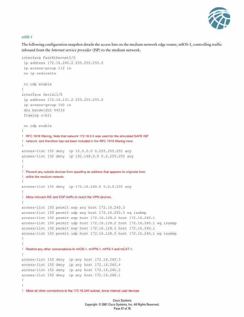
The following configuration snapshot details the access lists on the medium network edge router, mIOS-1, controlling traffic
inbound from the Internet service provider (ISP) to the medium network.
interface FastEthernet0/0 ip address 172.16.240.2 255.255.255.0 ip access-group 112 in no ip redirects
no cdp enable!interface Serial1/0 ip address 172.16.131.2 255.255.255.0 ip access-group 150 in dsu bandwidth 44210 framing c-bit
no cdp enable!! RFC 1918 filtering. Note that network 172.16.0.0 was used for the simulated SAFE ISP
! network, and therefore has not been included in the RFC 1918 filtering here.!access-list 150 deny ip 10.0.0.0 0.255.255.255 anyaccess-list 150 deny ip 192.168.0.0 0.0.255.255 any!!! Prevent any outside devices from spoofing an address that appears to originate from
! within the medium network.!access-list 150 deny ip 172.16.240.0 0.0.0.255 any!! Allow relevant IKE and ESP traffic to reach the VPN devices.
!access-list 150 permit esp any host 172.16.240.3access-list 150 permit udp any host 172.16.240.3 eq isakmpaccess-list 150 permit esp host 172.16.128.2 host 172.16.240.1access-list 150 permit udp host 172.16.128.2 host 172.16.240.1 eq isakmpaccess-list 150 permit esp host 172.16.128.5 host 172.16.240.1access-list 150 permit udp host 172.16.128.5 host 172.16.240.1 eq isakmp!!! Restrict any other conversations to mIOS-1, mVPN-1, mPIX-1 and mCAT-1.
!access-list 150 deny ip any host 172.16.240.3access-list 150 deny ip any host 172.16.240.4access-list 150 deny ip any host 172.16.240.2access-list 150 deny ip any host 172.16.240.1!!! Allow all other connections to the 172.16.240 subnet, since internal user devices
! translate to 172.16.240.0 addresses at the firewall as they access the Internet.!access-list 150 permit ip any 172.16.240.0 0.0.0.255!!! Block and log all other attempted access.
!access-list 150 deny ip any any log!!
The following configuration snapshot details the access lists that control traffic inbound from the medium network to the
ISP on the edge router.
! Allow TCP sessions that originated from the router to the management hosts
! (TACACS+, etc.). Management hosts 172.16.240.151 and 172.16.240.152 are the! NAT translated addresses at the firewall. !access-list 112 permit tcp host 172.16.240.151 host 172.16.240.2 establishedaccess-list 112 permit tcp host 172.16.240.152 host 172.16.240.2 established!!! Allow SSH connections originated from the management hosts to the router.
!access-list 112 permit tcp host 172.16.240.151 host 172.16.240.2 eq 22access-list 112 permit tcp host 172.16.240.152 host 172.16.240.2 eq 22!!! Necessary for allowing TFTP back from the management host to the router.
!access-list 112 permit udp host 172.16.240.151 host 172.16.240.2 gt 1024! !! Allow other devices on the 172.16.240 subnet to synchronize clocks to this device.
!access-list 112 permit udp 172.16.240.0 0.0.0.255 host 172.16.240.2 eq ntp!!! Allow internal devices to ping the Internet.
!access-list 112 permit icmp 172.16.240.0 0.0.0.255 any!!! Block all other attempts to access this router and log.
!access-list 112 deny ip any host 172.16.240.2 log!!! Permit all access to the Internet from hosts with 172.16.240.0 addresses.
The following configuration snapshot of the firewall details the Network Address Translation (NAT) configuration of the
PIX Firewall.
! In combination with the nonat access list, the below configuration does not allow
! NAT for sessions between internal devices (network 10.x.x.x to network 10.x.x.x), but! allows NAT for sessions between internal or remote access devices and the Internet.!global (outside) 100 172.16.240.101-172.16.240.150 netmask 255.255.255.0global (outside) 200 172.16.240.201-172.16.240.250 netmask 255.255.255.0nat (inside) 0 access-list nonatnat (inside) 100 10.0.0.0 255.0.0.0 0 0nat (pss) 0 access-list nonatnat (vpn) 200 10.3.7.0 255.255.255.0 0 0static (inside,vpn) 10.3.0.0 10.3.0.0 netmask 255.255.0.0 0 0static (inside,pss) 10.3.8.253 10.3.8.253 netmask 255.255.255.255 0 0static (inside,pss) 10.3.8.254 10.3.8.254 netmask 255.255.255.255 0 0!!! Translates the non-registered address of the public services server to a registered
! address, which can be accessed from the Internet.!static (pss,outside) 172.16.240.50 10.3.6.50 netmask 255.255.255.255 0 0!!! Translates the non-registered addresses of the management hosts to registered
! addresses so that managed devices outside the firewall can initiate sessions ! to the management servers. !static (inside,outside) 172.16.240.151 10.3.8.254 netmask 255.255.255.255 0 0static (inside,outside) 172.16.240.152 10.3.8.253 netmask 255.255.255.255 0 0!!!
access-list nonat permit ip 10.0.0.0 255.0.0.0 10.0.0.0 255.0.0.0 access-list nonat deny ip 10.0.0.0 255.0.0.0 any
The following configuration snapshot details the access control in place on the PIX Firewall. The name of the access list
denotes the location at which the inbound access control list (ACL) is placed.
Access-list “out” is placed inbound on the outside (public) interface of the firewall.
! Allow encrypted traffic from remote sites.
! access-list out permit ip 10.5.0.0 255.255.0.0 10.3.0.0 255.255.0.0 access-list out permit ip 10.6.0.0 255.255.0.0 10.3.0.0 255.255.0.0 !! RFC 1918 filtering. Note that network 172.16.0.0 was used for the simulated SAFE
! ISP network, and therefore has not been included in the RFC 1918 filtering here.!access-list out deny ip 10.0.0.0 255.0.0.0 any access-list out deny ip 192.168.0.0 255.255.0.0 any !! Allow external hosts access to the public services server for HTTP, SSL, FTP
! SMTP, and DNS.!access-list out permit tcp any host 172.16.240.50 eq www access-list out permit tcp any host 172.16.240.50 eq 443access-list out permit tcp any host 172.16.240.50 eq ftp access-list out permit tcp any host 172.16.240.50 eq smtp access-list out permit udp any host 172.16.240.50 eq domain !! Allow echo reply generated from the internal network (via NAT translated
! addresses) back into the firewall!access-list out permit icmp any 172.16.240.0 255.255.255.0 echo-reply !! Allow path MTU discovery (PMTUD) traffic through the firewall.
!access-list out permit icmp any 172.16.240.0 255.255.255.0 unreachable!! Allow syslog, TFTP, and TACACS+ management traffic in from remote sites.
!access-list out permit udp host 172.16.128.2 host 172.16.240.151 eq syslogaccess-list out permit udp host 172.16.128.2 host 172.16.240.152 eq syslogaccess-list out permit udp host 172.16.128.2 host 172.16.240.151 eq tftp access-list out permit tcp host 172.16.128.2 host 172.16.240.152 eq tacacs access-list out permit udp host 172.16.128.5 host 172.16.240.151 eq syslog access-list out permit udp host 172.16.128.5 host 172.16.240.152 eq syslogaccess-list out permit udp host 172.16.128.5 host 172.16.240.151 eq tftp access-list out permit tcp host 172.16.128.5 host 172.16.240.152 eq tacacs !! Permit syslog, TFTP, and TACACS+ which originates from the mIOS-1 router
!access-list out permit udp host 172.16.240.2 host 172.16.240.151 eq syslog access-list out permit udp host 172.16.240.2 host 172.16.240.152 eq syslog access-list out permit udp host 172.16.240.2 host 172.16.240.151 eq tftpaccess-list out permit tcp host 172.16.240.2 host 172.16.240.152 eq tacacs access-list out permit udp host 172.16.240.4 host 172.16.240.151 eq syslog access-list out permit udp host 172.16.240.4 host 172.16.240.152 eq syslog access-list out permit udp host 172.16.240.4 host 172.16.240.151 eq tftp access-list out permit tcp host 172.16.240.4 host 172.16.240.152 eq tacacs !
Access-list “in” is placed inbound on the inside (private) interface of the firewall.
! Allow echo from the inside network.
!access-list in permit icmp any any echo !!! Allow the internal DNS server to query the external DNS server for name
! translation.!access-list in permit udp host 10.3.2.50 host 10.3.6.50 eq domain !!! Allow internal corporate users web, SSL, and FTP access to the external public
! services server.!access-list in permit tcp 10.0.0.0 255.0.0.0 host 10.3.6.50 eq www access-list in permit tcp 10.0.0.0 255.0.0.0 host 10.3.6.50 eq 443access-list in permit tcp 10.0.0.0 255.0.0.0 host 10.3.6.50 eq ftp!! ! Allow mail transfer from the external mail server to the internal mail
! server.!access-list in permit tcp host 10.3.2.50 host 10.3.6.50 eq smtp !!! Allow Telnet access from the mgmt hosts to the mCAT-2 switch (does not support ! SSH) on the public services segment.
!access-list in permit tcp host 10.3.8.253 host 10.3.6.4 eq telnet access-list in permit tcp host 10.3.8.254 host 10.3.6.4 eq telnet !!! Deny all other access to the public services segment from the internal network.
!access-list in deny ip any 10.3.6.0 255.255.255.0!!! Permit all internal users access to the Internet.
! Allow mail originated from the public services host (external mail server)
! to the corporate intranet services host (internal mail server).!access-list pss permit tcp host 10.3.6.50 host 10.3.2.50 eq smtp !!! Deny all other traffic destined for addresses on the internal network.
!access-list pss deny ip any 10.3.0.0 255.255.0.0 !.!! Allow mail and DNS generated by the public services host to the Internet.
!access-list pss permit tcp host 10.3.6.50 any eq smtp access-list pss permit udp host 10.3.6.50 any eq domain !Access list “vpn” is placed inbound on the remote access VPN segment interface of the firewall. Remote VPN users are
assigned addresses in the 10.3.7.0 subnet via an address pool defined in the access control server. Remote dial-in users are
assigned addresses in the 10.3.8.0 subnet.
! Allow remote users web, SSL, and FTP access only to the public services server.
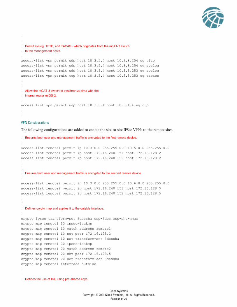
!access-list vpn permit ip 10.3.7.0 255.255.255.0 any access-list vpn permit ip 10.3.8.0 255.255.255.0 any !!! Permit syslog, TFTP, and TACAS+ which originates from the VPN concentrator,
! mVPN-1, to the management hosts.!access-list vpn permit udp host 10.3.5.5 host 10.3.8.254 eq tftp access-list vpn permit udp host 10.3.5.5 host 10.3.8.254 eq syslog access-list vpn permit udp host 10.3.5.5 host 10.3.8.253 eq syslog access-list vpn permit tcp host 10.3.5.5 host 10.3.8.253 eq tacacs !!! Allow the VPN concentrator to synchronize time with the
! internal router, mIOS-2.!access-list vpn permit udp host 10.3.5.5 host 10.3.4.4 eq ntp !!! Permit RADIUS authentication data which originates from the VPN concentrator to
! the management host.
!access-list vpn permit udp host 10.3.5.5 host 10.3.8.253 eq 1645!!! Permit syslog, TFTP, and TACAS+ which originate from the dial-in access
! router, mIOS-3, to the management hosts.!access-list vpn permit udp host 10.3.5.2 host 10.3.8.254 eq tftp access-list vpn permit udp host 10.3.5.2 host 10.3.8.254 eq syslog access-list vpn permit udp host 10.3.5.2 host 10.3.8.253 eq syslog access-list vpn permit tcp host 10.3.5.2 host 10.3.8.253 eq tacacs !!! Allow the dial-in access router, mIOS-3, to synchronize time with the
The following configurations are added to enable the site-to-site IPSec VPNs to the remote sites.
! Ensures both user and management traffic is encrypted to the first remote device.
!access-list remote1 permit ip 10.3.0.0 255.255.0.0 10.5.0.0 255.255.0.0 access-list remote1 permit ip host 172.16.240.151 host 172.16.128.2 access-list remote1 permit ip host 172.16.240.152 host 172.16.128.2 !!! Ensures both user and management traffic is encrypted to the second remote device.
!access-list remote2 permit ip 10.3.0.0 255.255.0.0 10.6.0.0 255.255.0.0 access-list remote2 permit ip host 172.16.240.151 host 172.16.128.5 access-list remote2 permit ip host 172.16.240.152 host 172.16.128.5 !!! Defines crypto map and applies it to the outside interface.
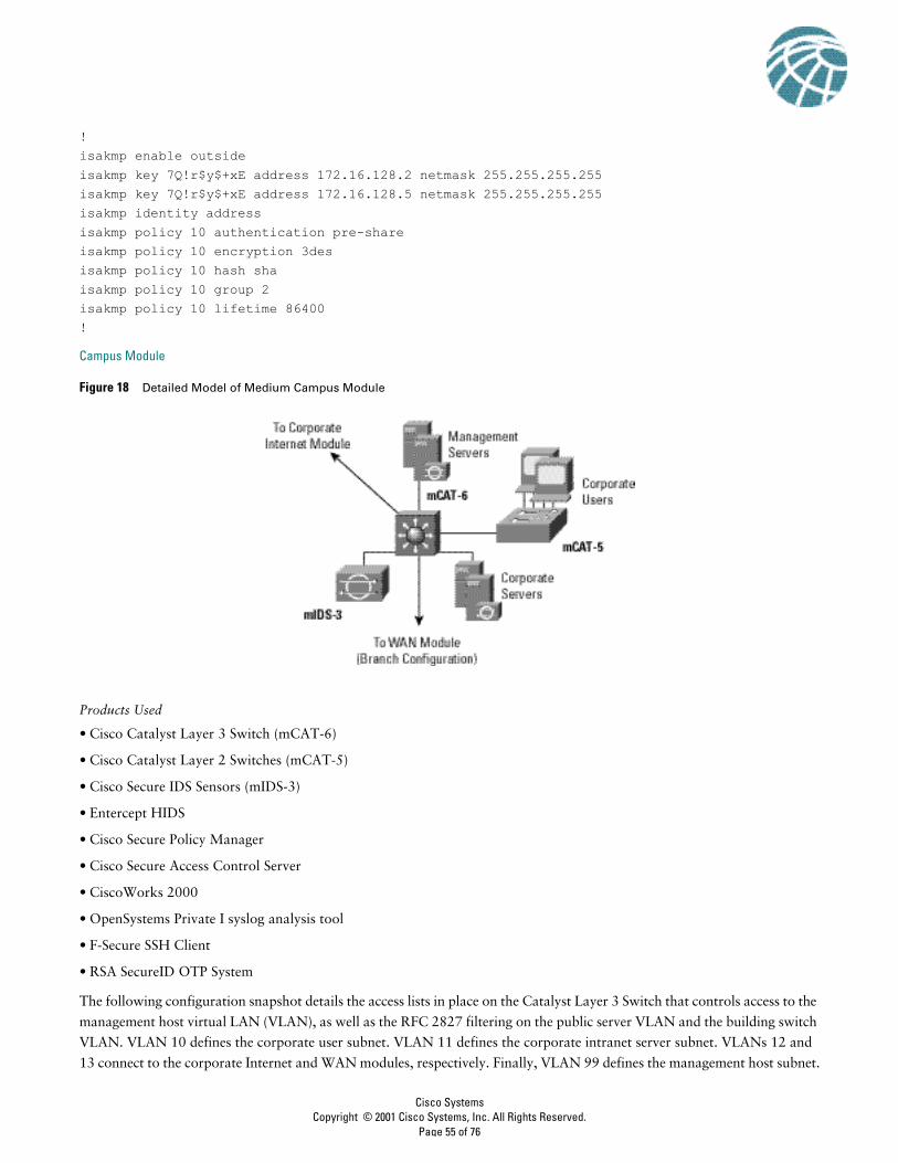
!crypto ipsec transform-set 3dessha esp-3des esp-sha-hmac crypto map remote1 10 ipsec-isakmpcrypto map remote1 10 match address remote1crypto map remote1 10 set peer 172.16.128.2 crypto map remote1 10 set transform-set 3desshacrypto map remote1 20 ipsec-isakmpcrypto map remote1 20 match address remote2crypto map remote1 20 set peer 172.16.128.5 crypto map remote1 20 set transform-set 3desshacrypto map remote1 interface outside!!! Defines the use of IKE using pre-shared keys.
!interface Vlan10 ip address 10.3.1.1 255.255.255.0 ip access-group 101 in no ip redirects no cdp enable!!! Corporate intranet server VLAN.
!interface Vlan11 ip address 10.3.2.1 255.255.255.0 ip access-group 102 in no ip redirects no cdp enable!!interface Vlan12 ip address 10.3.3.1 255.255.255.0 no ip redirects ip ospf authentication message-digest ip ospf message-digest-key 1 md5 7 134E031F4158140119 no cdp enable!interface Vlan13 ip address 10.3.9.1 255.255.255.0 no ip redirects ip ospf authentication message-digest ip ospf message-digest-key 1 md5 7 024D105641521F0A7E no cdp enable!! Management host VLAN.
!interface Vlan99 ip address 10.3.8.1 255.255.255.0 ip access-group 103 out no ip redirects no cdp enable!!! RFC 2827 filtering on corporate user VLAN.
!access-list 101 permit ip 10.3.1.0 0.0.0.255 anyaccess-list 101 deny ip any any!!! RFC 2827 filtering on corporate intranet server VLAN.
!access-list 102 permit ip 10.3.2.0 0.0.0.255 anyaccess-list 102 deny ip any any log!!! Example filtering for access to the management subnet (not complete).
Branch versus Headend ConsiderationsThe following configuration is added to the access list on the core switch to allow configuration and security management
traffic from the remotely managed devices to the management hosts, when the medium network is configured as a headend.
!interface FastEthernet0/1 port protected switchport access vlan 99 no cdp enable!interface FastEthernet0/2 port protected switchport access vlan 99 no cdp enable!!! Unused ports.
!interface FastEthernet0/3 port protected shutdown no cdp enable!interface FastEthernet0/4 port protected shutdown no cdp enable!!! Uplink to core switch mCAT-1
!interface GigabitEthernet0/1 switchport access vlan 99 no cdp enable!!!! Management interface to the switch.
!interface VLAN99 ip address 10.3.1.4 255.255.255.0 no ip directed-broadcast no ip route-cache!
• Cisco IOS Router with 3DES encryption support (rIOS-1)
• Cisco VPN 3002 Hardware Client (rVPN3002-1)
• Cisco Secure PIX Firewall (rPIX-1)
• Cisco VPN 3000 Software Client
• Cisco MicroHub (or integrated into Layer 3 device)
• Zone Alarm Pro Personal Firewall
The following are configuration snapshots from some of the SAFE remote-user designs.
rIOS-1 (Remote-Site Router Option)The following shows the configuration of the IPSec tunnels back to the corporate headquarters.
crypto isakmp policy 1 encr 3des authentication pre-share group 2crypto isakmp key 7Q!r$y$+xE address 172.16.240.1!!crypto ipsec transform-set 3dessha esp-3des esp-sha-hmac !crypto map remote1 10 ipsec-isakmp set peer 172.16.240.1 set transform-set 3dessha match address 101! !! The first lines of the following access-list specifies all traffic from
! network 10.5.0.0 to networks 10.3.0.0 will be encrypted.! ! The last two lines of the access-list allow encryption of all configuration and! security management traffic from the remote site router to the headquarters! management hosts.!access-list 101 permit ip 10.5.0.0 0.0.255.255 10.3.0.0 0.0.255.255access-list 101 permit ip host 172.16.128.2 host 172.16.240.151access-list 101 permit ip host 172.16.128.2 host 172.16.240.152!!
The following shows the access control on the private side (FastEthernet0/0) and the public side (FastEthernet0/1) of the
router, as well as the application of the Cisco IOS Firewall to the interfaces.
interface FastEthernet0/0 ip address 10.5.1.2 255.255.255.0 ip access-group 105 in ip nat inside ip inspect remote_fw in!interface FastEthernet0/1 ip address 172.16.128.2 255.255.255.0 ip access-group 102 in ip nat outside crypto map remote1!! IKE and ESP traffic must be allowed from the headquarters IPSec peer. All
! traffic from network 10.5.0.0 to networks 10.3.0.0 must also! be allowed. Finally, traffic from the management hosts is allowed.!access-list 102 permit ip 10.3.0.0 0.0.255.255 10.5.0.0 0.0.255.255access-list 102 deny ip 10.0.0.0 0.255.255.255 any access-list 102 deny ip 192.168.0.0 0.0.255.255 anyaccess-list 102 permit icmp any host 172.16.128.2 echo-replyaccess-list 102 permit icmp any host 172.16.128.2 unreachableaccess-list 102 permit esp host 172.16.240.1 host 172.16.128.2access-list 102 permit udp host 172.16.240.1 host 172.16.128.2 eq isakmpaccess-list 102 permit tcp host 172.16.240.151 host 172.16.128.2 eq 22access-list 102 permit tcp host 172.16.240.152 host 172.16.128.2 eq 22access-list 102 permit tcp host 172.16.240.152 eq tacacs host 172.16.128.2access-list 102 permit udp host 172.16.240.151 host 172.16.128.2 gt 1023access-list 102 deny ip any any log!!! RFC 2827 filtering only allows 10.5.0.0 addresses to access both the corporate
! headquarters and the Internet.!access-list 105 permit ip 10.5.0.0 0.0.255.255 anyaccess-list 105 deny ip any any log!The following shows the configuration of many-to-one NAT on the router. All devices within the remote site that access the
Internet will use the public address of the router.
ip nat pool remote_pool 172.16.128.2 172.16.128.2 netmask 255.255.255.0ip nat inside source route-map nat_internet pool remote_pool!route-map nat_internet permit 10 match ip address 104!access-list 104 deny ip 10.5.0.0 0.0.255.255 10.0.0.0 0.255.255.255access-list 104 permit ip 10.5.0.0 0.0.255.255 any
rPIX-1 (Remote-Site Firewall Option)The following shows the configuration of the IPSec tunnels back to the corporate headquarters.
crypto ipsec transform-set 3dessha esp-3des esp-sha-hmac crypto map remote1 10 ipsec-isakmpcrypto map remote1 10 match address remote1crypto map remote1 10 set peer 172.16.240.1 crypto map remote1 10 set transform-set 3desshacrypto map remote1 interface outsideisakmp enable outsideisakmp key 7Q!r$y$+xE address 172.16.240.1 netmask 255.255.255.255 isakmp identity addressisakmp policy 10 authentication pre-shareisakmp policy 10 encryption 3desisakmp policy 10 hash shaisakmp policy 10 group 2isakmp policy 10 lifetime 86400!! The first line of the following access-list specifies all traffic from
! network 10.6.0.0 to networks 10.3.0.0 will be encrypted.! ! The last two lines of the access-list allow encryption of all configuration and! security management traffic from the remote site firewall to the headquarters! management hosts.!access-list remote1 permit ip 10.6.0.0 255.255.0.0 10.3.0.0 255.255.0.0 access-list remote1 permit ip host 172.16.128.5 host 172.16.240.151 access-list remote1 permit ip host 172.16.128.5 host 172.16.240.152 !
The following shows the addressing and access control on the private side (inside) and the public side (outside) of the firewall.
nameif ethernet0 outside security0nameif ethernet1 inside security100!ip address outside 172.16.128.5 255.255.255.0ip address inside 10.6.1.1 255.255.255.0!access-group out in interface outsideaccess-group in in interface inside!! RFC 2827 filtering only allows 10.6.0.0 addresses to access both the corporate
! headquarters and the Internet.
!access-list in permit ip 10.6.0.0 255.255.0.0 any !! Allows encrypted traffic from corporate headquarters.
!access-list out permit ip 10.3.0.0 255.255.0.0 10.6.0.0 255.255.0.0
! ! RFC 1918 filtering. Note network 172.16.x.x was not included in the
! filter here since it is used to simulate the ISP in the lab.
!access-list out deny ip 10.0.0.0 255.0.0.0 any access-list out deny ip 192.168.0.0 255.255.0.0 any !! Allow echo replies and path MTU discovery (PMTU) traffic.
!access-list out permit icmp any host 172.16.128.5 echo-reply access-list out permit icmp any host 172.16.128.5 unreachable!! Allow ESP and IKE traffic from the corporate headquarters peer.
!access-list out permit esp host 172.16.240.1 host 172.16.128.5 access-list out permit udp host 172.16.240.1 host 172.16.128.5 eq isakmp
The following shows the configuration of many-to-one NAT on the firewall. All devices within the remote site that access
the Internet will use the public address of the firewall.
global (outside) 100 interfacenat (inside) 0 access-list nonatnat (inside) 100 10.6.1.0 255.255.255.0 0 0!! The access-list prevents any traffic destined for the corporate site from using
! address translation.
!access-list nonat permit ip 10.6.0.0 255.255.0.0 10.0.0.0 255.0.0.0 access-list nonat deny ip 10.6.0.0 255.255.0.0 any !
Port RedirectionThe port-redirection attack is a type of trust-exploitation attack that uses a compromised host to pass traffic through a
firewall that would otherwise be dropped. Consider a firewall with three interfaces and a host on each interface. The host
on the outside can reach the host on the public services segment (commonly referred to as a DMZ), but not the host on the
inside. The host on the public services segment can reach the host on both the outside and the inside. If hackers were able to
compromise the public services segment host, they could install software to redirect traffic from the outside host directly to
the inside host. Though neither communication violates the rules implemented in the firewall, the outside host has now
achieved connectivity to the inside host through the port-redirection process on the public services host. An example of an
application that can provide this type of access is netcat. For more information, refer to http://www.avian.org.
Port redirection can be mitigated primarily through the use of proper trust models (as mentioned earlier). If we assume that
a system is under attack, host-based IDS can help detect and prevent a hacker installing such utilities on a host.
Unauthorized AccessAlthough unauthorized-access attacks are not a specific type of attack, they refer to most attacks executed in networks today.
In order for someone to brute-force attack a Telnet login, he/she must first get the Telnet prompt on a system. Upon
connection to the Telnet port, a message might indicate: “authorization required to use this resource.” If the hacker continues
to attempt access, his/her actions become “unauthorized.” These kinds of attacks can be initiated on both the outside and
inside of a network.
Mitigation techniques for unauthorized-access attacks are very simple. They involve reducing or eliminating the ability of a
hacker to gain access to a system using an unauthorized protocol. An example would be preventing hackers from having
access to the Telnet port on a server that needs to provide Web services to the outside. If a hacker cannot reach that port, it
is very difficult to attack it. The primary function of a firewall in a network is to prevent simple unauthorized-access attacks.
One of the most popular types of firewall is a stateful firewall. These firewalls inspect traffic in both directions and
dynamically open ports as applications require them. For example, active FTP negotiates a specific port for the data transfer.
The stateful firewall will see this information in the packet and will allow that port to communicate between the server and
client. This is very different than a standard packet filtering device which has no application awareness. These devices merely
look at layer 3 and 4 data when making an access control decision. In the FTP example above, the administrator would need
to manually open all TCP high ports (>1023) from the outside in order for FTP to be successful.
Virus and Trojan Horse ApplicationsThe primary vulnerabilities for end-user workstations are viruses and Trojan horse attacks. Viruses refer to malicious
software that is attached to another program to execute a particular unwanted function on a user's workstation. An example
of a virus is a program that is attached to command.com (the primary interpreter for windows systems), which deletes certain
files and infects any other versions of command.com that it can find. A Trojan horse is different only in that the entire
application was written to look like something else, when in fact it is an attack tool. An example of a Trojan horse is a
software application that runs a simple game on the user’s workstation. While the user is occupied with the game, the Trojan
horse mails a copy of itself to every user in the user’s address book. Then other users get the game and play it, thus spreading
the Trojan horse.
These kinds of applications can be contained through the effective use of antivirus software at the user level and potentially
at the network level. Antivirus software can detect most viruses and many Trojan horse applications and prevent them from
spreading in the network. Keeping up-to-date with the latest developments in these sorts of attacks can also lead to a more
effective posture against these attacks. As new virus or Trojan applications are released, enterprises need to keep up-to-date
with the latest antivirus software, and application versions.
Cisco Systems has more than 190 offices in the following countries. Addresses, phone numbers, and fax numbers are listed on the
C i s c o . c o m W e b s i t e a t w w w . c i s c o . c o m / g o / o f f i c e s .
Argentina • Australia • Austria • Belgium • Brazil • Bulgaria • Canada • Chile • China • Colombia • Costa Rica • Croatia • Czech Republic • Denmark • Dubai, UAEFinland • France • Germany • Greece • Hong Kong • Hungary • India • Indonesia • Ireland • Israel • Italy • Japan • Korea • Luxembourg • Malaysia • Mexico • TheNetherlands • New Zealand • Norway • Peru • Philippines • Poland • Portugal • Puerto Rico • Romania • Russia • Saudi Arabia • Scotland • Singapore • SlovakiaSlovenia • South Africa • Spain • Sweden • Switzerland • Taiwan • Thailand • Turkey • Ukraine • United Kingdom • United States • Venezuela • Vietnam • Zimbabwe
Corporate HeadquartersCisco Systems, Inc.170 West Tasman DriveSan Jose, CA 95134-1706USAwww.cisco.comTel: 408 526-4000
800 553-NETS (6387)Fax: 408 526-4100
European HeadquartersCisco Systems Europe11, Rue Camille Desmoulins92782 Issy Les Moulineaux Cedex 9Francewww.cisco.comTel: 33 1 58 04 60 00Fax: 33 1 58 04 61 00
Americas HeadquartersCisco Systems, Inc.170 West Tasman DriveSan Jose, CA 95134-1706USAwww.cisco.comTel: 408 526-7660Fax: 408 527-0883


![SAFE Security For More Information - tu-sofia.bgtzokev.tu-sofia.bg/uploads/Lectures/CCNARS/CCNA2/SAFE_Poster[1].pdf · SAFE Security Reference Architecture The Cisco The Foundation](https://static.documents.pub/doc/80x56/5b98443f09d3f2ef798bb8d8/safe-security-for-more-information-tu-sofia-1pdf-safe-security-reference.jpg)


