345


Connecting an actuator to the AS-Interface with 3/22ASIsafeConnecting to PROFIBUS with PROFIsafe 3/24Directly connecting sensors to PROFIBUS with 3/25PROFIsafeConnecting a sensor to fail-safe SIMATIC input 3/25modulesConnecting actuators to PROFIBUS with PROFIsafe 3/32
4 Fail-safe communications using standard fieldbuses
4.1 PROFIsafe 4/2Features/benefits 4/3PROFIsafe applications 4/4PROFIsafe-capable products 4/4PROFIsafe in the 7-layer communications model 4/4PROFIsafe functions 4/5PROFIsafe interacting with TIA 4/7
4.2 ASIsafe 4/7Overview 4/7Customer benefits 4/8Highlights 4/9Applications 4/9Principle design and function 4/9Integrating into TIA 4/14
5 Safety industrial controls
5.1 SIRIUS position switches 5/25.2 SIRIUS Emergency Stop 5/75.3 SIRIUS command and signaling devices 5/85.4 SIRIUS safety relays 5/11
Overview 5/11Features 5/11Applications 5/11Product family/product groups 5/12Design 5/13Functions 5/13Integration 5/15Examples 5/16Technical Data 5/18
5.5 ASIsafe 5/20Product family/product groups 5/20Technical data 5/22Example - packaging machine 5/23
5.6 ET 200S Safety Motor Starter Solution 5/24Overview 5/24Applications 5/24Features 5/25ET 200S Motorstarter Solution Local 5/26ET 200S Motorstarter Solution PROFIsafe 5/30Structure 5/37Technical Data 5/38
Content
1 Regulations and Standards
1.1 General Information 1/21.2 Regulations and Standards 1/3
in the European Union (EU)Basic principles of the legal 1/3requirements in Europe*Health and Safety at the workplace in the EU 1/4Safety of machinery in Europe 1/5Process technology in Europe 1/20Furnace systems in Europe 1/25
1.3 Legal requirements and standards 1/26regarding safety at work in North AmericaUS - general 1/26Machine safety 1/27Process industry in the US 1/30Safety Regulations and Standards in Canada 1/31
1.4 Safety requirements for machines in Japan 1/34 1.5 Important Addresses 1/35
2 Specification and design ofsafety-relevant controls for machines
2.1 Overview 2/22.2 Design and implementation process of 2/3
the machine, risk assessment, process to reduce risks
2.3 Does the protective measure depend on 2/9the control?
2.4 Specification of the safety requirements 2/142.5 Design and implementation of (safety-related) 2/15
controls according to IEC 62061Philosophy/theory 2/17Process to design a safety-related control system 2/23SRECS
2.6 Designing and implementing safety-related 2/34parts of a control according to EN 954-1(ISO 13849-1 (rev))
2.7 Specification and design of safety-relevant 2/37controls for machines in the United States
3 Connecting sensors/actuators
3.1 Overview 3/23.2 Features 3/33.3 Standards - an overview 3/43.4 Connecting sensors/actuators 3/6
Conventionally connecting sensors whithout 3/12using safety-related communications viafieldbusesConnecting sensors/actuators whithout 3/13safety-related communicationConnecting to AS-Interface with ASIsafe 3/19Connecting sensors to AS-Interface with ASIsafe 3/20
6 Fail-safe optical sensors
6.1 SIGUARD LS4 laser scanners 6/2Overview 6/2Application of SIGUARD LS4 laser scanner 6/3 Product families/product groups 6/4Design 6/5Functions 6/6Integration into the system 6/7Application information 6/8Calculating the protective field 6/9Technical Data 6/12
6.2 SIGUARD light curtains and light grids 6/14Overview 6/14Features 6/14Applications 6/16Functions 6/21
6.3 SIGUARD light barriers 6/286.4 SIGUARD switching strips 6/32
7 Fail-safe controllers SIMATIC Safety Integrated
7.1 Overview 7/27.2 Features 7/37.3 Applications 7/57.4 Product group/product family 7/67.5 Engineering 7/107.6 Structure 7/117.7 Functions 7/127.8 Examples 7/147.9 Technical Data 7/18
8 Fail-safe motion control systems
8.1 SINUMERIK Safety Integrated - 8/2the safety package for machine toolsBrief description 8/3Equipment components 8/5System prerequisites 8/8Safe stopping process 8/9Monitoring speed and position 8/13Logically combining safety-related process signals 8/14Vertical axes are protected from dropping 8/15Integrated and partially-automated acceptance 8/19reportForced checking procedure for SINUMERIK 8/21Safety IntegratedConnecting sensors/actuators - basics 8/22Connecting sensors/actuators via separate 8/24hardware I/O from the PLC and NCConnecting sensors/actuators via ET 200S 8/30PROFIsafe fail-safe modulesApplication examples 8/31Certification 8/31
8.2 Safety Unit 8/328.3 Safety Integrated for Motion Control Systems 8/34
9 Fail-safe drives
9.1 MASTERDRIVES and SIMODRIVE 611universal 9/29.2 SINAMICS Safety Integrated 9/49.3 SIMATIC ET 200S FC frequency converters
Overview 9/6Benefits 9/7Applications 9/7Design 9/8Functions 9/8Integration 9/10Technical data 9/12
10 References
10.1 Fail-safe SIMATIC controllers in the body shop 10/2of Opel Belgium
10.2 Safety technology for Toyota Canada 10/410.3 Building automobile bodies with distributed 10/6
safety for Ford Australia10.4 PLC-based safety concept in the manufacture 10/9
of truck wheels for Michelin, Germany10.5 Exciting trip through Madame Tussauds 10/1210.6 Seed production – a pump system for 10/14
chemicals in controlled using ASIsafe10.7 AS-Interface simplifies safety at work 10/16
for UPS10.8 CROWN Vourles – safety in the packaging 10/19
industry with Safety Motor Starter SolutionPROFIsafe
10.9 More safety in the automobile industry 10/2210.10 New standard for machine tools 10/2310.11 Safety when testing products used for 10/25
safety at work10.12 A synthesis of speed & safety 10/3010.13 Safe standstill in the printing industry 10/32
11 Appendix
11.1 Terminology and abbreviations 11/211.2 References 11/611.3 Contact – Internet Hotlines 11/611.4 Seminars available for safety technology, 11/7
Standards and Directives11.5 List of contents 11/15

Foreword
Regulations and Standards 1
Specification and design of safety-relevant controls for machines 2
Connecting sensors/actuators 3
Fail-safe communications using standard fieldbuses 4
Safety industrial controls 5
Fail-safe optical sensors 6
Appendix 11
Fail-safe controllers SIMATIC Safety Integrated 7
Fail-safe motion control systems 8
Fail-safe drives 9
References 10

Helmut GierseA&D Group Board
Applications in the area of machinesafety or process technology – state-of-the-art technologies in the automationprocess - demand the highest degreeof safety for man, machine and theenvironment.
This “Safety Integrated” System Manual,that has already been updated a mul-tiple number of times, indicates thathazards and dangers, caused by func-tional faults, can either be reduced orremoved.
From the sensor through the evalua-tion equipment up to the safety-relatedimplementation, “Safety Integrated”with the SIRIUS, SIGUARD, SIMATIC,and SINUMERIK/SIMODRIVE productgroups provides maximum protectionagainst functional faults.
These product groups have alreadyproven themselves for many years in standard automation solutions and that worldwide. Since the safety-related communications via PROFIBUS and via the actuator-sensor-interface -ASIsafe have been certified, thesecomponents can now also be com-bined in the system.
In addition to the conventional wiringbetween the individual components,by using standard fieldbus systems,also for safety technology, additionalvalue is added thanks to the overallsystem integration. This allows morecost-effective engineering, as the samecomponents are used and the plant andsystem availability is simultaneouslyincreased thanks to improved diagnos-tics.
Open and integrated
An automation system mainly com-prises standard components such asstandard PLC, drives etc.
Depending on the application, thecomponent of safety technology of a complete system can vary widely.Independent of the application area,the safety level always comprises achain of sensors, evaluation devicesand actuators for a safety-relatedcondition of the plant or machines.Today, the two levels of a plant orsystem - standard and safety relatedtechnology - are strictly separated.Generally, different engineering tech-niques and tools are used for thesetwo levels. This not only results inhigher costs associated with personneltraining, but also in many cases, thesetwo levels can only be linked with con-siderable expenditure.
The requirements regarding cost-savingpotential can be especially fulfilled byselecting the appropriate installationsystem. In standard technology, themove to distributed concepts and theuse of modern fieldbuses have alreadyresulted in significant cost savings.Further cost savings in the future willbe achieved by transferring additionalsafety-related signals along existingstandard fieldbuses.
2 Safety Integrated System Manual
Dear Readers,

“Safety Integrated” is the practical andconsequential implementation of thisconcept.By applying this concept, standard aswell as the safety components mergetogether to create a standard, integrat-ed and transparent cost-effective over-all system.
Complex wiring for diagnostics andfeedback signals can be eliminated.With Safety Integrated, cost-savings are achieved both in the planning aswell as in the installation and service/maintenance phases thanks to stan-dard, integrated engineering tools andtechniques as well as visualization con-cepts.
Changes and revisions in the Standardsarea mean that mechanical design engi-neers must modify their methodologywhen it comes to planning safety-relat-ed machine and plant control systems.
We can support this using easy-to-understand documentation andarranging workshops for applyingthese Standards as well as interpretingthese Standards.
As a result of intensive informationexchange with users, the required ele-ments will be defined and developedstep-by-step but also in the up andcoming years, additional products willround-off the portfolio even more.
It goes without saying that trends inthe automation technology, that arealready influencing today's automationenvironment, will also soon be foundin Safety Integrated. Examples includethe PROFINET safety communicationprotocol that will be introduced in thenear future and wireless communica-tions. Further, Safety Integrated willinitiate certain trends. As a result ofthe example set, standards will be set both regarding support as well as qualitative and quantitative proof. And as a result of enthusiastic, con-vinced users, human responsibility and economic sense will be combined.
Our mission, together with our cus-tomers, is to expand the level of com-petence for functional safety!
Sincerely,
Helmut Gierse
Safety Integrated System Manual 3
Head of the business field Automation, Software and InformationTechnology (ASI)TÜV Industrie Service GmbH, KölnTÜV Rheinland Group
Automation systems and componentsare responsible for safety-related tasksin many different applications(machines and conveyor systems,process industry, building technologyetc.). This means that the health andsafety of persons as well as protectingequipment and the environmentdepend on the correct functioning ofthe relevant systems and components.
Today, the correct functioning ofsystems and components is handledunder the term of “Functional Safety”.This is especially documented inStandard IEC 61508 “Functional safetyof electrical, electronic and program-mable electronic safety-related sys-tems” that was ratified in the Spring of2000. In the meantime, this Standardhas also been published as EN 61508and DIN EN 61508 / VDE 0803.
This standard is considered as a basisstandard independent of the applicationand addresses those parties involved indeveloping application-specific stan-dards, as well as the contents (describ-ing measures for the safety concept,fault-preventing and fault-controllingmeasures for hardware and software)– essentially to manufacturers of safe-ty-related systems and components.
This has already been accepted by theStandards groups oriented to specificapplications. The first examples includeIEC 61511 for the process industry andEN 50156 for the electrical equipmentof furnace control systems. In the areaof safety of machines, IEC 62061 isexpected for safety-related control sys-tems of machines. It goes without say-ing that in the area of machine safety, application-specific standards - suchas e.g. EN 954 - also have to be taken
into account. Work is underway for this Standard to integrate the perspec-tives of IEC 61508 in reference to e.g.quantitative parameters and quanti-ties. A VDMA, Specification sheet24200-1 has been published for thearea of building automation. This alsotakes into account the perspectives ofIEC 61508.
In the future, it can be expected thatadditional User Associations will usethe existing Basis Standard for theirwork in order to standardize the re-quirements placed on safety-relatedsystems and components. This espe-cially makes sense, because the prin-ciples involved with risk evaluation,risk reduction and the safety-relatedfunctions can be applied to the widestrange of applications. It would thenmean, that from the perspective of theapplication, only a few aspects wouldhave to be evaluated - such as e.g. thespecified response times of the safecondition for the particular process.
This means that manufacturers will beable to develop systems and compo-nents which will be able to be used forsafety tasks, with comparable degreesof risk, in various applications. To real-ize this, the following generally appli-cable data must be available for eachparticular component:
4 Safety Integrated System Manual
Foreword
Heinz Gall

• Maximum Safety Integrity Level that can be achieved
• Hardware fault tolerance in conjunc-tion with the proportion of safety-related failures (sum of the failures that fail in the safe direction plus thefailures, detected and controlled by the internal diagnostics) referred to the sum of all of the failures
• Dangerous probability of failure• Information and instructions for
user programming configuration and operation
These specified criteria then allowsafety-related functions to be evaluat-ed in the application; generally, thesesafety-related functions comprise sen-sors, logic (e.g. PLC) and actuators aswell as communications between thesevarious components.
Field devices, sensors and actuatorsare increasingly incorporating more“intelligence”. This is the reason thatbus systems will be increasingly usedto establish safety-related communica-tions between the components of asafety-related function.
Over the past couple of years, progresshas been made in the area of standard-ized, safety-related bus systems.
This progress comprises, on one hand,the development of a basis for the“Testing and certification of bus sys-tems to transfer safety-related mes-sages” and on the other hand, concep-tual tests of such bus systems havebeen successfully completed.
In the meantime, safety-relateddevices/components for operation onthese bus systems are available in themarketplace. This means that devicesfrom different manufacturers can beoperated on standardized, safety-relat-ed bus systems.
In this case, it is up to manufacturersto develop additional devices for thesebus systems.
The TÜV Rheinland Group [GermanTechnical Inspectorate, RheinlandGroup], especially the business areaAutomation, Software and InformationTechnology, supports manufacturers,engineers and users in implementingthe above mentioned safety-relatedtasks - and that worldwide (Europe,US, Japan).
After having been successfully tested,systems and components receive theFS test mark “Functional Safety” inorder to document that they are in
compliance with the requirements laid-down in the various Standards.Further, management systems associ-ated with functional safety “FSM” -referred to the lifecycle of the compo-nents/systems - and experts/engineersof functional safety “FS Exp/ FS Eng”will be qualified and certified.
Engineers and users will be supportedin order to achieve the functional safe-ty - also for the application and theimplemented safety function.
Cologne, 2nd of September, 2004
Safety Integrated System Manual 5

ManagementAutomation, Software and Electronics IQSETÜV Automotive GmbH, TÜV SÜD Gruppe, München [GermanTechnical Inspectorate SOUTH Group,Munich]
System certification
The SIMATIC S7 Distributed Safety is, assafety-related programmable system,certified by TÜV SÜD [German TechnicalInspectorate, SOUTH]. This means thatit is suitable for use in safety-relatedapplications with a high potential haz-ard risk - e.g. production systems,machinery construction, process tech-nology and offshore processes.
Certification by TÜV SÜD
The testing and certification by TÜVSÜD - as independent and certifiedthird-party - results in some significantadvantages such as
• Clear product positioning in the international competitive environ- ment as high-quality sophisticatedsystem, certified by a testing body that has a leading role worldwide
• High degree of security for the future when defining basic testing principles
• Testing is carried-out independentlyof internal company interest
• High degree of acceptance in the market
• This certification is clearly recog-nized worldwide.
Advantages of certification for endusers
When the engineering guidelines arecarefully observed, end users no longerhave to give any thought to the func-tional safety. The control has “integrat-ed” recognized functional safety.
Acceptance authorities therefore onlyhave to evaluate that the control sys-tem has been correctly used and thatthe engineering guidelines have beenobserved.
The existing certification is used asbasis and must no longer be ques-tioned.
Certification procedure
The certification was aligned to IEC61508. Further, DIN V VDE 0801 wasalso applied. This is the reason thatdeterministic as well as probabilisticfault models were used.
A high-quality fault detection and faultcontrolling are required as a result ofthe architecture of the processing/eval-uation unit.
The proof of this high fault detectionrate was not only a challenge forSiemens AG but also for the evaluationcarried-out by TÜV SÜD. As a result ofthe close cooperation and integrationinto the complete developmentprocess, TÜV SÜD was able to make itsown detailed picture of the system andthe arguments presented. The experi-ence and knowhow of the TÜV SÜDwas repeatedly drawn on as a result of the many innovative principles. Thereason for this was to ensure that the
system remained in basic compliancewith IEC 61508.
Another requirement is the manage-ment of functional safety in accor-dance with IEC 61508. Also here, TÜVSÜD was involved in the process asevaluator from the very beginning.
In addition, from the start, the objec-tive was to implement the certificationaccording to the relevant UL standards.This is the reason that the UL wereclosely involved in the certificationprocess through TÜV SÜD. This meantthat work wasn't carried-out twice -time-consuming and cost-intensivework.
Basis of the certification
Several sub-areas must be consideredwithin the scope of successful certifica-tion. These don't only involve the func-tional safety, but also aspects such asprimary safety, electromagnetic com-patibility and also requirements regard-ing applications. The user only has asafety-related and available system afterall of the requirements of the sub-areashave been fulfilled.
6 Safety Integrated System Manual
Foreword
Alfred Beer
Testing standards
Functional safety
The functional safety was tested basedon the IEC 61508 Standard - interna-tionally recognized to represent state-of-the-art technology. UL 1998 wasalso used in order to be compliant withthe requirements relating the US.
Primary safety
The relevant Standards regarding pri-mary safety must be fulfilled to com-plete and specify the technical require-ments from the above listed standardsand Directives. Here, it is especiallyimportant to mention the genericstandard EN 61131-2 and UL 508.
Electromagnetic compatibility
In addition to fulfilling the requirementsfrom the EMC Directive, the specificrequirements listed in EN 61131-2were taken into account.
Application-related Standards
Both European (e.g. EN 60204-1 andEN 954-1) as well as also American(e.g. NFPA 79) Standards regardingmachine safety are taken into account.The reason for this is the differentapplication possibilities of the system.
EN 298 was essentially taken into con-sideration for furnace control systems.
Summary
As a result of its distributed architectureand the use of diverse software struc-tures, the SIMATIC S7 Distributed Safetyrepresents a real milestone when itcomes to certified systems. Significantadvantages are also obtained due tothe fact that safety-related and non-safety-related components can becombined. The system can be used inmany different applications due to thewidely based basic testing procedures.This was also supported due to the factthat UL Standards are complied with.
Additional information on the servicesof the TÜV SÜD regarding systems andapplications:
www.tuev-sued.de/iqse
Safety Integrated System Manual 7
Head of "Accident Prevention and Product Safety" in the BG Institute for Occupational Safety and Health – BGIA, Sankt Augustin
New technologies in the name ofsafety
If you compare the safety controls fromthe eighties with state-of-the-art pro-ducts of today, then the advantages ofintelligent computer-based systems insafety-related systems become quiteclear:
• New sampling-type sensors allow a finely graduated safety technology to be created, optimally adapted to the particular application
• Computer channels, operating with high clock frequencies, result in ex-tremely short response times
• Intelligent software allows aging processes to be identified before they can have a dangerous effect
• Safety fieldbus systems significantlyreduce the amount of wiring and therefore potential problems, espe-cially when troubleshooting.
However, new technologies are onlybeneficial for safety technology, if me-asures to control and avoid faults arealready taken into account at the startof development (refer to IEC 61508).By applying new technologies, notonly is a higher degree of safety achie-ved, but the system availability is alsoincreased even if in some cases it isnecessary to significantly intervene inthe development process. The expe-rience gained from over 250,000 ofour customers' systems in the fieldclearly indicates that high technologyapplied in this fashion is also reallysafe.
Safety technology through dialoginstead of checking
Since the middle of the eighties, theBGIA and several other testing bodieshave carried-out tests on complex sa-fety systems that accompanied the de-velopment process. The testing bodyno longer comes into play as a che-cking entity at the end of the develop-ment process, but accompanies thecreation of the product from a testing-related perspective from the first ideaup to when the product goes into se-ries production. Only then can com-plex systems be certified in the firstplace. Based on an accepted specifica-tion, the testing body checks the mea-sures taken at specific milestones inthe lifecycle of a safety system anddevelops fault-preventing techniqueswithin the scope of the validation.Using these techniques, which aredefined in the above-mentioned Stan-dards, the testing body ensures thatthe development process of a productis perfect. This is the reason why com-plex safety technology should be con-sidered more a process rather than aproduct.
8 Safety Integrated Systemhandbuch
Vorwort
Dr. rer. nat. M. Schaefer

Increasing the acceptance of safe-ty technology
The new technology allows safety tobe integrated into a machine or plantdirectly using the functional control.In newly developed CNC control sys-tems with integrated safety technolo-gy, reduced speed when setting-upthe machine or safe operating stopare implemented using additionalsoftware without external monitoringdevices. This means, for the user, thatsafety is embedded in the control andthe likelihood of faults is significantlyreduced. In the same invisible way, byapplying concepts based on standardhardware to safely transfer data, va-rious controls - and even completeproduction plants and systems - canbe safely networked with one another.This therefore eliminates additionalmanual operations – e.g. parameteri-zing safety-related devices and equip-ment. Safety-related data can be cen-trally managed and made available.
All of these measures eliminate thebarriers for the use of safety technolo-gy and increase the level of acceptance.
Safety technology from a cost per-spective
Especially in the nineties, cost becamean increasingly important issue in sa-fety technology. Although the deve-lopment processes for complex safetytechnology are extremely cost-intensi-ve, safety, integrated using the soft-ware can be realized at a favourablecost for the individual product. Fur-thermore, downtimes are reduced as a result of the far more efficient dia-gnostics capability due to the use ofsafety computer systems.
The German Regulatory Bodies percei-ve it to be an important task to alsoaccompany the development proces-ses, sketched-out above, also in thefuture and to also further promotethis. And of course, this Manual de-monstrates that this is a safe route totake – and a route that is extremelypromising.
For the German Regulatory Bodies,innovation and prevention are impor-tant issues in working together. Oursociety requires ongoing innovation.This secures the competitiveness andfacilitates a lifestyle and working me-thods to help people generally. TheGerman Regulatory Bodies thereforepromote such innovation that plays arole in reducing all types of risks andhazards or which improves workingtechniques and procedures.
In order to present especially outstan-ding developments for increased safe-ty and health at the workplace to a lar-ger trade public, a German Safety atWork prize in the category of innovati-ve products in the commercial acci-dent prevention & insurance associa-tion will be awarded at the "Healthand Safety at Work Exhibition in 2005"
(for more detailed information, referto www.hvbg.de Webcode 860665) .
Safety Integrated Systemhandbuch 9

Objectives
The goal of safety technology is to keepthe potential hazards for man and theenvironment as low as possible byapplying and utilizing the appropriatetechnology. However, this should beachieved without imposing unneces-sary restrictions on industrial produc-tion, the use of machines and theproduction of chemicals. By applyinginternationally harmonized regulations,man and the environment should beprotected to the same degree in everycountry. At the same time, differencesin competitive environments, due todifferent safety requirements, shouldbe eliminated.
In the various regions and countriesaround the globe, there are differentconcepts and requirements when itcomes to guaranteeing safety. Thelegal concepts and the requirementsregarding what has to be proven andhow, regarding whether there is suffi-cient safety, are just as different as theassignment of the levels of responsibil-ity. For example, in the EU, there arerequirements placed both on the manu-facturer of a plant or system as well asthe operating company which are reg-ulated using the appropriate EuropeanDirectives, Laws and Standards. On theother hand, in the US, requirementsdiffer both at a regional and even at alocal level.
However, throughout the US there is abasic principle that an employer mustguarantee a safe place of work. In thecase of damage, as a result of the pro-duct liability laws, a manufacturer canbe made liable for his product. On theother hand, in other countries andregions, other principles apply.
What is important for machinery man-ufacturers and plant construction com-panies is that the legislation and rulesof the location always apply in whichthe machine or plant is being operat-ed. For instance, the control system ofa machine, which is operated and usedin the US, must fulfill US requirements,even if the machine manufacturer (i.e.OEM) is based in Europe. Although thetechnical concepts with which safety is to be achieved are subject to cleartechnical principles, it is still importantto observe as to whether legislation orspecific restrictions apply.
Functional safety
From the perspective of the object tobe protected, safety cannot be segre-gated. The causes of danger and alsothe technical measures to avoid themcan vary widely. This is the reason thata differentiation is made between vari-ous types of safety, e.g. by specifyingthe particular cause of a potential haz-ard. For instance, the term “electricalsafety” is used if protection has to beprovided against electrical hazards andthe term “functional safety” is used ifthe safety is dependent on the correctfunction.
This differentiation is now reflected inthe most recent Standards, in so muchthat there are special Standards thatare involved with functional safety. Inthe area of machine safety, EN 954 1)
and IEC 62061 specifically address therequirements placed on safety-relatedcontrol systems and therefore concen-trate on functional safety. In the basissafety Standard IEC 61508 2), IECaddresses the functional safety of elec-trical, electronic and programmableelectronic systems independent of anyspecific application area.
In IEC 61508, functional safety is definedas “part of the overall safety relating tothe EUC* and the EUC control systemwhich depends on the correct func-tioning of the E/E/PE** safety-relatedsystems, other technology safety-relat-ed systems and external risk reductionfacilities”.
2 Safety Integrated System Manual
1 Regulations and Standards
1.1 General Information
* EUC: Equipment under control
** E/E/PE: Electrical, electronic, programmable
electronic
1) corresponds to ISO 13849
2) also EN 61508 and DIN EN 61508 / VDE 0803

In order to achieve functional safety ofa machine or plant the safety-relatedparts of the protection and controldevices must function correctly andwhen a fault condition develops, mustbehave so that the plant or system re-mains in a safe condition or is broughtinto a safe condition.
To realize this, proven technology isrequired, which fulfills the demandsspecified by the relevant Standards.The requirements to achieve functionalsafety are based on the following basicgoals:
• Avoiding systematic faults,• Controlling systematic faults,• Controlling random faults or failures.
The measure for the level of achievedfunctional safety is the probability ofthe occurrence of dangerous failures,the fault tolerance and the quality thatshould be guaranteed by avoiding sys-tematic faults. In the Standards, this isexpressed using various terms. In IEC61508: “Safety Integrity Level” (SIL), inEN 954: “Categories” and ISO 13849-1" Performance Level" (PL) (this hasstill not been ratified).
Standardization goals
The demand to make plant, machinesand other equipment as safe as possi-ble using state-of-the-art technologycomes from the responsibility of themanufacturers and users of equipmentfor their safety. All safety-significantaspects of using state-of-the-art tech-nology are described in the Standards.By maintaining and fulfilling thesestandards it can be ensured that state-of-the-art technology is applied there-fore ensuring that the company erect-ing a plant or the manufacturer pro-ducing a machine or a device has ful-filled his responsibility for ensuringsafety.
Note: The Standards, Directives andLaws, listed in this Manual are just aselection to communicate the essentialgoals and principles. We do not claimthat this list is complete.
Basic principles of the legalrequirements in Europe*
Legislation states that we must focusour efforts “... on preserving and pro-tecting the quality of the environment,and protecting human health throughpreventive actions” (Council Directive96/82/EC “Seveso II”).
It also demands “Health and safety atthe workplace” (Machinery Directive,workplace, health and safety legisla-tion, ...). Legislation demands that thisand similar goals are achieved for vari-ous areas (“Areas which are legislated”)in the EU Directives. In order to achievethese goals, legislation places demandson the operators and users of plant,and the manufacturers of equipmentand machines. It also assigns theresponsibility for possible injury ordamage.
The EU Directives• specify requirements for plants/
systems and their operating compa-nies to ensure the health and safety of personnel and the quality of the environment;
• include regulations regarding healthand safety at the workplace (mini-mum-requirements);
• define product requirements(e.g. for machines) to ensure the health and safety of the user;
Safety Integrated System Manual 3
11.2 Regulations andStandards in theEuropean Union (EU)
* EFTA states also use the
concept of the EU.
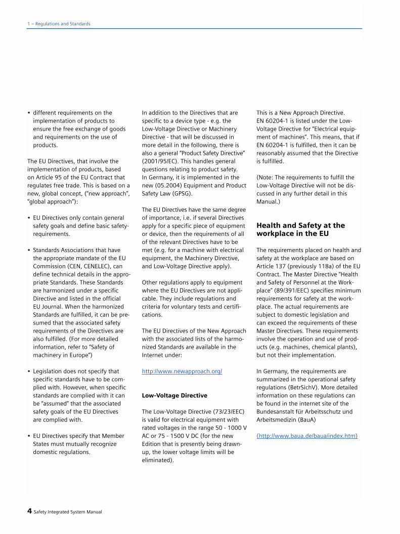
• different requirements on theimplementation of products to ensure the free exchange of goods and requirements on the use ofproducts.
The EU Directives, that involve theimplementation of products, based on Article 95 of the EU Contract thatregulates free trade. This is based on anew, global concept, (“new approach”,“global approach”):
• EU Directives only contain general safety goals and define basic safety-requirements.
• Standards Associations that have the appropriate mandate of the EU Commission (CEN, CENELEC), can define technical details in the appro-priate Standards. These Standardsare harmonized under a specific Directive and listed in the official EU Journal. When the harmonized Standards are fulfilled, it can be pre-sumed that the associated safety requirements of the Directives are also fulfilled. (For more detailedinformation, refer to “Safety of machinery in Europe”)
• Legislation does not specify that specific standards have to be com-plied with. However, when specific standards are complied with it can be “assumed” that the associated safety goals of the EU Directives are complied with.
• EU Directives specify that Member States must mutually recognize domestic regulations.
In addition to the Directives that arespecific to a device type - e.g. the Low-Voltage Directive or MachineryDirective - that will be discussed inmore detail in the following, there isalso a general “Product Safety Directive”(2001/95/EC). This handles generalquestions relating to product safety. In Germany, it is implemented in thenew (05.2004) Equipment and ProductSafety Law (GPSG).
The EU Directives have the same degreeof importance, i.e. if several Directivesapply for a specific piece of equipmentor device, then the requirements of allof the relevant Directives have to bemet (e.g. for a machine with electricalequipment, the Machinery Directive,and Low-Voltage Directive apply).
Other regulations apply to equipmentwhere the EU Directives are not appli-cable. They include regulations andcriteria for voluntary tests and certifi-cations.
The EU Directives of the New Approachwith the associated lists of the harmo-nized Standards are available in theInternet under:
http://www.newapproach.org/
Low-Voltage Directive
The Low-Voltage Directive (73/23/EEC)is valid for electrical equipment withrated voltages in the range 50 - 1000 VAC or 75 - 1500 V DC (for the newEdition that is presently being drawn-up, the lower voltage limits will beeliminated).
This is a New Approach Directive. EN 60204-1 is listed under the Low-Voltage Directive for “Electrical equip-ment of machines”. This means, that ifEN 60204-1 is fulfilled, then it can bereasonably assumed that the Directiveis fulfilled.
(Note: The requirements to fulfill theLow-Voltage Directive will not be dis-cussed in any further detail in thisManual.)
Health and Safety at theworkplace in the EU
The requirements placed on health andsafety at the workplace are based onArticle 137 (previously 118a) of the EUContract. The Master Directive “Healthand Safety of Personnel at the Work-place” (89/391/EEC) specifies minimumrequirements for safety at the work-place. The actual requirements aresubject to domestic legislation and can exceed the requirements of theseMaster Directives. These requirementsinvolve the operation and use of prod-ucts (e.g. machines, chemical plants),but not their implementation.
In Germany, the requirements aresummarized in the operational safetyregulations (BetrSichV). More detailedinformation on these regulations canbe found in the internet site of theBundesanstalt für Arbeitsschutz undArbeitsmedizin (BauA)
(http://www.baua.de/baua/index.htm)
4 Safety Integrated System Manual
1 – Regulations and Standards

Safety of machinery inEurope
Machinery Directive (98/37/EC)*
With the introduction of a commonEuropean market, a decision was madeto harmonize the national standardsand regulations of all of the EC MemberStates. This meant that the MachineryDirective, as an internal Directive, hadto be implemented in the domesticlegislation of the individual MemberStates. In Germany, the contents of theMachinery Directive were implementedas the 9th Decree of the EquipmentSafety law. For the Machinery Directive,this was realized with the goal of hav-ing unified protective goals and to re-duce trade barriers. The area of appli-cation of the Machinery Directive cor-responding to its definition “Machinerymeans an assembly of linked parts orcomponents, at least one of whichmoves...” and is extremely extensive.With the Change Directives, the area of application has been subsequentlyextended to “safety components” and“interchangeable equipment.” TheMachinery Directive involves the im-plementation of machines.
“Machinery” is also defined as anassembly of machines which, in orderto achieve the same end, are arrangedand controlled so that they function asan integral whole"..
The application area of the MachineryDirective thus ranges from a basicmachine up to a complete plant.
The Machinery Directive has 14Articles and 7 Annexes.
The basic health and safety require-ments in the Appendix I of theDirective must be complied with forthe safety of machinery. In selectingthe most appropriate methods, themanufacturer must apply the followingprinciples (Annex I Paragraph 1.1.2):
a) “Machinery must be constructedthat it is fitted for its function, andcan be adjusted and operated with-out putting persons at risk when theseoperations are carried out under theconditions forseen by the manufacturer.”“The measures must exclude any riskof accident...”
Safety Integrated System Manual 5
1
Fig. 1/1Overview of the Machinery Directive
Machinery Directive
Annex Article
Application area,selling, marke-ting, freedom of movement, health and safetyrequirements Art. 1 – Art. 7
Certification procedure
Art. 8 – Art. 9
CE marking, protection against arbitrary fulfillment
Art. 10 – Art. 12
Coming into force, transitional regulations,cancellation of the regulations
Art. 13 – Art. 14
Essential health and safety requirements relating to the design and construction of
I – machinery, and 3• interchangeable equipment 5• safety components 10
Contents ofII 1. EC Declaration of Conformity for 4
– machinery, and 5• interchangeable equipment 8• safety components
2. Manufacturer's declaration for 4– specific components of the machinery– non-functioning machines
III CE marking 10
IV Types of machinery andsafety components,where the procedure acc. to Article 8must be applied.
V EC Declaration of conformity for– machinery, and 8
• interchangeable equipment• safety components
VI EC type examination for – machinery and 8
• interchangeable equipment• safety components
VII Minimum criteria for testing bodies 9
* Presently, discussions are taking place in the
various Associations of the EU about a new
Edition of the Machinery Directive. It is present-
ly not possible to make definitive statements
regarding the changes that can be expected
and when it will be published.
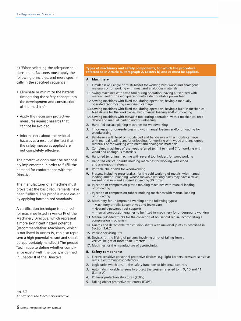
b) "When selecting the adequate solu-tions, manufacturers must apply thefollowing principles, and more specifi-cally in the specified sequence:
• Eliminate or minimize the hazards (integrating the safety-concept into the development and construction of the machine);
• Apply the necessary protective-measures against hazards thatcannot be avoided;
• Inform users about the residual hazards as a result of the fact thatthe safety measures applied are not completely effective.
The protective goals must be responsi-bly implemented in order to fulfill thedemand for conformance with theDirective.
The manufacturer of a machine mustprove that the basic requirements havebeen fulfilled. This proof is made easierby applying harmonized standards.
A certification technique is required for machines listed in Annex IV of theMachinery Directive, which represent a more significant hazard potential.(Recommendation: Machinery, whichis not listed in Annex IV, can also repre-sent a high potential hazard and shouldbe appropriately handled.) The precise“technique to define whether compli-ance exists” with the goals, is definedin Chapter II of the Directive.
6 Safety Integrated System Manual
1 – Regulations and Standards
A. Machinery
1. Circular saws (single or multi-blade) for working with wood and analogous materials or for working with meat and analogous materials
1.1.Swing machines with fixed tool during operation, having a fixed bed with manual feed of the workpiece or with a demountable power feed
1.2.Sawing machines with fixed tool during operation, having a manually operated reciprocating saw-bench carriage
1.3.Sawing machines with fixed tool during operation, having a built-in mechanical feed device for the workpieces, with manual loading and/or unloading
1.4.Sawing machines with movable tool during operation, with a mechanical feed device and manual loading and/or unloading
2. Hand-fed surface planing machines for woodworking
3. Thicknesses for one-side dressing with manual loading and/or unloading for woodworking
4. Band-saws with fixed or mobile bed and band-saws with a mobile carriage, with manual loading and/or unloading, for working with wood and analogous materials or for working with meat and analogous materials
5. Combined machines of the types referred to in 1 to 4 and 7 for working with wood and analogous materials
6. Hand-fed tenoning machine with several tool holders for woodworking
7. Hand-fed vertical spindle molding machines for working with wood and analogous materials
8. Portable chain saws for woodworking
9. Presses, including press-brakes, for the cold working of metals, with manual loading and/or unloading, whose movable working parts may have a travel exceeding 6 mm and a speed exceeding 30 mm/s
10. Injection or compression plastic-molding machines with manual loading or unloading
11. Injection or compression rubber-molding machines with manual loading or unloading
12. Machinery for underground working or the following types:– Machinery or rails: Locomotives and brake-vans– Hydraulic-powered roof supports– Internal combustion engines to be fitted to machinery for underground working
13. Manually-loaded trucks for the collection of household refuse incorporating a compression mechanism
14. Guards and detachable transmission shafts with universal joints as described inSection 3.4.7..
15. Vehicle-servicing lifts
16. Devices for the lifting of persons involving a risk of falling from a vertical height of more than 3 meters
17. Machines for the manufacture of pyrotechnics
B. Safety components
1. Electro-sensitive personnel protective devices, e.g. light barriers, pressure-sensitivemats, electromagnetic detectors
2. Logic units which ensure the safety functions of bimanual controls
3. Automatic movable screens to protect the presses referred to in 9, 10 and 11 (Letter A)
4. Rollover protection structures (ROPS)
5. Falling-object protective structures (FOPS)
Types of machinery and safety components, for which the procedurereferred to in Article 8, Paragraph 2, Letters b) and c) must be applied.
Fig. 1/2
Annex IV of the Machinery Directive
Standards
To sell, market or operate products,these products must fulfill the basicsafety requirements of the EU Directives.Standards can be extremely helpfulwhen it involves fulfilling these safetyrequirements. In this case, a differenti-ation must be made between harmo-nized European Standards and otherStandards, which although are ratified,have still not been harmonized under a specific Directive, as well as othertechnical rules and regulations whichare also known as “National Standards”in the Directives.
Ratified standards define the recog-nized state-of-the-art technology. Thismeans, that by proving that he hasapplied them, a manufacturer can provethat he has fulfilled what is recognizedto be state-of-the-art technology.
All Standards, that are ratified as Euro-pean Standards, must be included,unchanged in the National Standardsof the Member States. This is indepen-dent of whether they are harmonizedunder one Directive or not. Existingdomestic Standards, handling the samesubject, must then be withdrawn. Thismeans that over time, a series of stan-dards (without any conflicting state-ments) will be created in Europe.
Note: IEC 61508 “Functional safety of electrical/electronic/programmableelectronic safety-related systems” is animportant Standard that is not harmo-nized under an EU Directive.It is ratified as EN 61508. (The prelimi-nary Standards DIN V VDE 0801 andDIN V 19250 and 19251 were there-fore withdrawn by August 2004.)There, where EN 61508 is referencedin a harmonized standard, it is a stan-
dard that is “also applicable” to theassociated harmonized Standard.
Harmonized European Standards
These are drawn up by the two stan-dards organizations CEN (Comité Euro-péen de Normalisation) and CENELEC(Comité Européen de NormalisationÉlectrotechnique) as mandate from theEU Commission in order to specify therequirements of the EU Directives for a specific product. These must be pub-lished in the official Council Journal of the European communities. TheseStandards (EN Standards) will be pub-lished in the official Council Journal ofthe European Communities and mustbe then included in the domestic stan-dards without any changes.
They are used to fulfill the basic healthand safety requirements and the pro-tective goals specified in Annex I of theMachinery Directive.
In Germany, the contact partner forCEN/CENELEC is DIN and DKE.
By fulfilling such harmonized standards,there is an “automatic presumption ofconformity,” i.e. the manufacturer canbe trusted to have fulfilled all of thesafety aspects of the Directive as longas they are covered in the particularStandard. However, not every EuropeanStandard is harmonized in this sense.The listing in the European documen-tation is definitive The updated lists arealso available in the Internet
(Address:http://www.newapproach.org/)
Safety Integrated System Manual 7
1B. “Safety component”
Means a component, provided that it is not interchangeable equipment, which themanufacturer or his authorized representative established in the Community places on the market to fulfill a safety function when in use and the failure or malfunctioning of which endangers the safety or health of exposed persons.
In conjunction with the information regarding the Machinery Directive, this can be interpreted as follows.
“Safety components are characterized by the fact that they must have an appropriate purpose - specified by the manufacturer (as safety component) in the sense of the Directive. In the explanation regarding the Directive, in Section 76 it is defined that components ”that must fulfill an operating function“ are not safety components. This also applies if their failure would result in a potential hazard and these of course must be safe. An example of a non-safety component is given in Section 81 using the hoisting cable [of a crane]. The main function of the cable is to operationally raise and lower loads, but not to provide ”protection against a load dropping". When this sense is transferred, e.g. to drives, this means that generally they are not safety components as their main function is to drive a machine.
On the other hand, components with a double function - for example two-handswitches - are then considered to be a safety component if the safety function (protection of the operator) has far more significance that the operating function (initiating operations) (Section 80 of information on the Machinery Directive).
Individual parts, that must be assembled with additional parts or software programs that are separately purchased, in order to implement a safety function, can themselvesnot be safety components. This also applies if these individual components are expressly intended to be used in safety components.
The Machinery Directive defines, in Chapter 1 Article 1 (2):

1 – Regulations and Standards
European Standards for the safety ofmachinery are hierarchically structuredas follows
• A Standards, also known as Basic Standards.
• B Standards, also known as Group Standards.
• C Standards, also known as Product Standards.
The structure is shown in the diagramabove.
Type A Standards/Basic Standards
Type A Standards contain basic termi-nology and definitions for all machines.This also includes EN ISO 12100 (earli-er EN 292) “Safety of machinery, basic
terminology, general design guide-lines.”
Type A Standards primarily addressthose parties setting B and C Stan-dards. The techniques and methods discussed there to minimize risks canalso be helpful for manufacturers ifthere are no applicable C Standards.
8 Safety Integrated System Manual
Fig. 1/3
The European Standards for safety of machines
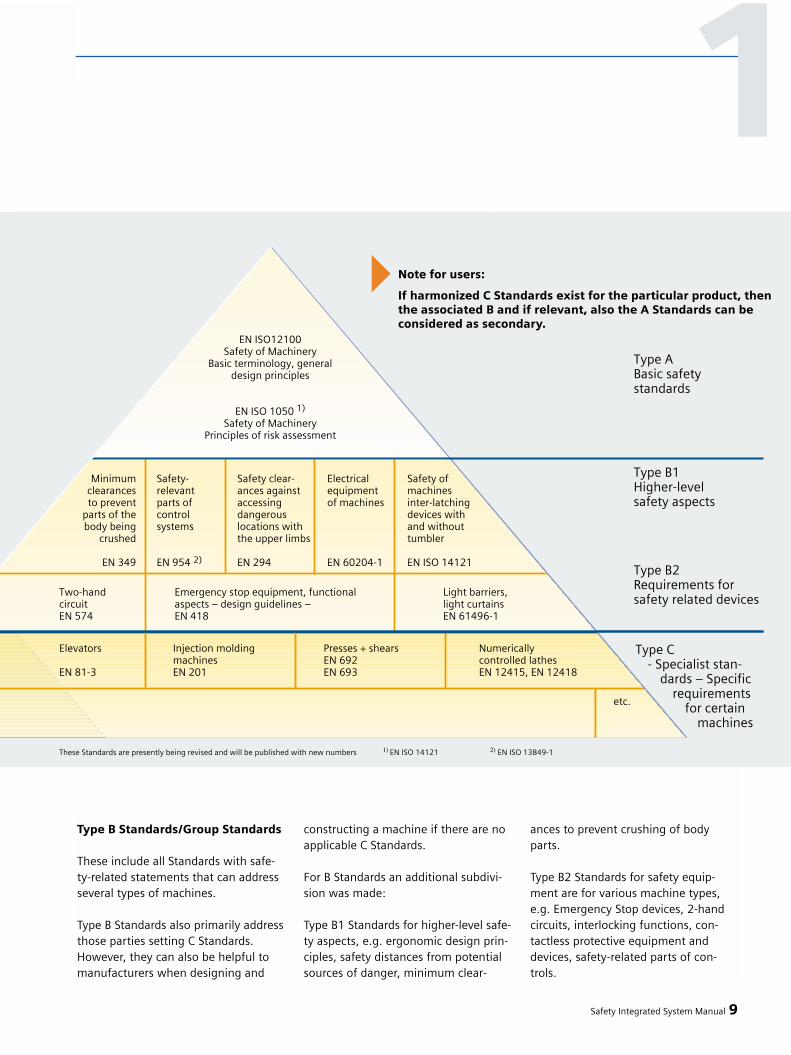
Type B Standards/Group Standards
These include all Standards with safe-ty-related statements that can addressseveral types of machines.
Type B Standards also primarily addressthose parties setting C Standards.However, they can also be helpful tomanufacturers when designing and
constructing a machine if there are noapplicable C Standards.
For B Standards an additional subdivi-sion was made:
Type B1 Standards for higher-level safe-ty aspects, e.g. ergonomic design prin-ciples, safety distances from potentialsources of danger, minimum clear-
ances to prevent crushing of bodyparts.
Type B2 Standards for safety equip-ment are for various machine types,e.g. Emergency Stop devices, 2-handcircuits, interlocking functions, con-tactless protective equipment anddevices, safety-related parts of con-trols.
Safety Integrated System Manual 9
1Note for users:
If harmonized C Standards exist for the particular product, thenthe associated B and if relevant, also the A Standards can beconsidered as secondary.

Type C Standards/ProductStandards
These involve Standards for specificmachines - e.g. for machine tools,woodworking machines, elevators/lifts,packaging machinery, printing machinesand others.
The European Standards are structuredso that general statements that arealready included in type A or type Bstandards are not repeated. Referencesto these are made in type C Standards
Product Standards include machinery-specific requirements. These require-ments, under certain circumstances,deviate from the Basic and GroupStandards. The Type C Standard/ProductStandard has absolutely the higher pri-ority for the machinery constructionOEM. They (the machinery OEMs) canthen assume that they fulfill the basicrequirements of Annex I of the Machi-nery Directive (automatic presumptionof conformity).
If there is no Product Standard for aparticular machine, then Type B Stan-dards can be applied for orientationpurposes when designing and con-structing machinery.
In order to provide a method to har-monize the basic requirements of theDirective, with the mandate of the ECcommission, harmonized standardswere drawn-up in the technical com-mittees of the CEN and CENELEC formachinery and machinery groups foralmost all areas. Drawing-up standardsessentially involves representativesfrom the manufacturer of the particu-lar machinery, the regulatory bodies,such as Trade Associations as well asusers. A complete list of all of the listedStandards as well as the activities asso-
ciated with Standards - with mandatednew Standards for the future - are pro-vided in the Internet under:
http://www.newapproach.org/
Recommendation: Technology is pro-gressing at a tremendous pace whichis also reflected in changes made tomachine concepts. For this reason,especially when using Type C Standards,they should be checked to ensure thatthey are up-to-date. It should also benoted that it is not mandatory to applythe Standard but instead, the safetyobjective must be achieved.
Domestic Standards
If there are no harmonized EuropeanStandards or they cannot be appliedfor specific reasons, then a manufac-turer can apply the “DomesticStandards”. All of the other technicalrules fall under this term, e.g. also theaccident prevention regulations andstandards, which are not listed in theEuropean Council Journal (also IEC orISO Standards which were ratified asEN). By applying ratified standards, themanufacturer can prove that recog-nized state-of-the-art technology wasfulfilled. However, when such stan-dards are applied, the above men-tioned “automatic presumption of con-formity” does not apply.
Risk evaluation/assessment
As a result of their general design andfunctionality, machines and plants rep-resent potential risks. Therefore, theMachinery Directive requires a riskassessment for every machine and, ifrelevant, risk reduction, so that theremaining risk is less than the tolerable
risk. The following Standards should beapplied for the techniques to evaluatethese risks • EN ISO 12100 “Safety of machinery –
basic terminology, general design guidelines” and
• EN 1050 “Safety of machinery, guidelines to evaluate risks”
EN ISO 12100 mainly describes therisks to be considered and designguidelines to minimize risk, EN 1050focuses on the iterative process withrisk assessment and risk reduction toachieve safety. (refer to Chapter 2 foran explanation of this technique.)
Risk assessment
Risk assessment is a sequence of stepsthat allows hazards, which are causedby machines, to be systematicallyinvestigated. Where necessary, the riskassessment phase is followed by riskreduction. The iterative process isobtained by repeating this procedure(refer to Fig. 1/5). Using this process,hazards, as far as possible, can be elim-inated and the appropriate protectivemeasures can be applied.
Risk assessment encompasses• Risk analysis
a) Determining the limits of themachine (EN ISO 12100, EN 1050 Para. 5)
b) Identifying the hazards(EN ISO 12100, EN 1050 Para. 6)
c) Techniques to assess the risk(EN 1050 Para. 7)
• Risk evaluation (EN 1050 Para. 8)
After risks have been estimated, a riskevaluation is made as part of an itera-tive process to achieve safety. In thiscase, a decision has to be made
10 Safety Integrated System Manual
1 – Regulations and Standards

Safety Integrated System Manual 11
1
Fig. 1/4 Risk elements
Fig. 1/5
Iterative process to achieve safety in accordance with EN 1050
Note: EN 292-1 /-2 referenced in EN 1050 have in the meantime been replaced by EN ISO 12100-1 /-2.

whether it is necessary to reduce arisk. If the risk is to be further reduced,suitable protective measures must beselected and applied. The risk evalua-tion process must then be repeated.
Risk elements are defined as a supporttool to evaluate risks. Fig. 1/4 clearlyshows the interrelationship betweenthese risk elements.
If the required degree of safety has still not been reached, measures arerequired to further reduce the risk.
The risk must be reduced by suitablydesigning and implementing themachine. For instance, using suitablecontrol or protective measures for thesafety functions (also refer to theSection “Requirements of the MachineryDirective”). If the protective measuresinvolve interlocking or control functions,then these must be configured in accor-dance with EN 954. Further, electroniccontrol and bus systems must also incompliance with IEC / EN 61508. As analternative to EN 954, EN 62061 canbe used for electrical and electroniccontrol systems.
Residual risk (EN 1050)
Safety is a relative term in our techni-cal environment. Unfortunately, it isnot possible to implement the so-called“zero risk guarantee” where nothingcan happen under any circumstance.The residual risk is defined as: Risk thatremains after the protective measureshave been implemented.
In this case, protective measures re-present all of the measures to reducerisks.
Reducing risks
In addition to applying structural mea-sures, risk reduction for a machine canalso be realized using safety-relatedcontrol functions. Specific require-ments must be observed when imple-menting these control functions, grad-uated according to the magnitude ofthe risk. These are defined in EN 954-1and, for electrical control systems,especially with programmable elec-tronics, in IEC 61508.
The requirements placed on safety-re-lated parts of control systems are grad-uated according to the magnitude ofthe risk and the necessary risk reduc-tion. For this purpose, EN 954-1 defines“Categories” and in its Annex B descri-bes a technique to select the suitablecategory to design the safety-relatedparts of a control. New risk diagramswill be provided in the new Edition (EN ISO 13849-1), that instead ofcategories, will result in hierarchicallygraduated levels.
IEC 62061 uses “Safety Integrity Level”(SIL) to achieve this graduation. This is a quantified measure for the safety-related performance of control. Thenecessary SIL is determined accordingto the principle of the risk evaluationaccording to EN 1050. A technique todefine the necessary Safety IntegrityLevel (SIL) is described in Appendix Aof the Standard.
It is always important - independent of which Standard is applied - that allparts of the control of the machinethat are involved in implementing thesafety-related functions clearly fulfillthese requirements.
For details, refer to Chapter 2.
Note: The load circuits of drives andmotors also belong to the control of amachine.
When designing and implementing thecontrol it is necessary to check whetherthe requirements of the selected Cate-gory or of the SIL are actually fulfilled.The requirements to achieve the neces-sary Safety Performance are structureddifferently in EN 954 and IEC. This isthe reason that the requirementsregarding checking are also structureddifferently. For a design according toEN 954, the details for the validationand what has to be observed aredescribed in Part 2 (new designation,EN ISO 13849-2). The requirements tovalidate a design in compliance withIEC 62061 are described in the Standard.
The next table provides a brief sum-mary of the requirements for theCategories according to EN 954-1:1996. Basic requirements for configuringcontrol systems are defined in the vari-ous categories. These are intended tomake the systems tolerant to hardwarefailures. These requirements will par-tially change with the new Edition asEN ISO 13849-1 that is scheduled toappear in the immediate future.
Additional aspects must be taken intoconsideration for more complex con-trol systems, especially programmableelectronic systems, so that
• Random hardware failuresare controlled,
• Systematic faults/errors in the hard-ware and the software are avoidedand
12 Safety Integrated System Manual
1 – Regulations and Standards

• Systematic faults/errors in the hard-ware and software are controlled,
and sufficient functional safety isachieved for safety-critical tasks. The international Standard IEC 61508(identical to IEC 61508) defines therequirements and for contactless (elec-tronic protective devices such as lightgrids or laser scanners, IEC / EN 61496.The scope of the required measures isalso graduated corresponding to therisk reduction required.
The most recent technical develop-ments allows complex systems to beused for safety-related functions aslong as these fulfill the requirementsof IEC 61508. In order to take this intoaccount, the new Standard IEC 62061was developed for machine controlsand the existing EN 954-1 was revised.The latter will be published with thenew designation ISO 13849-1. Both of these standards are intendedto make it possible for the user to con-figure safety-related controls usingsuitable electrical and electronic com-ponents without having to apply IEC61508 themselves.
IEC 62061 assumes that the electronicdevices used already fulfill IEC 61508and describes a concept to also imple-ment complex and sophisticated safetyfunctions. This concept specificallyaddresses companies that integratemachine control systems and allow theSafety Performance that is achieved tobe quantified without complicated cal-culations.
Safety Integrated System Manual 13
1Category1) Summary of requirements System behavior2) Principles to
achieve safety
B The safety-related parts of control The occurrence of a faultsystems and/or their protective can lead to the loss ofequipment, as well as their com- the safety functionponents, shall be designed, con-structed selected, assembled andcombined in accordance with rele-vant standards so that they canwithstand the expected influence.
1 The requirements of B shall apply. The occurrence of aWell-proven components fault can result inand well-proven safety the loss of theprinciples must be applied. safety function,
but the probability of occurrence isless than inCategory B.
2 The requirements of B and the – The occurrence of ause of well-tried safety principles fault can lead to theshall apply. loss of the safetyThe safety function shall be checked function betweenat suitable intervals by the machine the checks.control system. – The loss of the
safety functionis detected bythe check.
3 The requirements of B and the – If the individualuse of well-proven safety fault occurs, theprinciples must be fulfilled. safety functionSafety-related parts shall be always remains.designed, so that: – Some but not– a single fault in any of these all faults will
parts does not lead to the loss be detected.of the safety function, and – Accumulation
– whenever reasonably of undetected faultspracticable, the single can lead to the lossfault is detected. of the safety function
4 The requirements of B and the – If faults occur,use of well-proven safety the safety function principles must be fulfilled. alwaysSafety-related parts shall be remains.designed so that: – The faults will be– a single fault in any of these detected in time to
parts does not lead to a loss prevent the loss ofof the safety function and the safety function.
– the single fault is detected at orbefore the next demand upon the safety function. If this is not possible, then an accumulation of faults shall not lead to a loss of the safety function
1) The categories are not intended to be used in any given order or in any given hierarchy in respect ofsafety requirements.
2) The risk assessment will indicate whether the total or partial loss of the safety function(s) arising fromfaults is acceptable.
Mainly characterized byselection ofcomponents
Mainlycharacterized bystructure
Fig. 1/6
Description of the requirements for
Categories acc. to EN 954-1
The concept of the future ISO 13849-1is restricted to specific, basic architec-tures and integrates the essential andnecessary requirements from IEC61508. The requirements for safety-related parts of controls based on elec-tro-mechanical components has beensupplemented with respect to EN 954-1 so that also here, it is possible tohierarchically graduate the safety per-formance in a quantifiable fashion.
Please refer to Chapter 2 to decide asto whether ISO 13849 or IEC 62061should be applied.
Validation
In this case, validation means that thesafety functionality to be achieved ischecked and evaluated. The purpose ofvalidation is to confirm the definitionsand the level of the conformity of thesafety-related parts of the control with-in the overall definition of the safetyrequirements at the machine. Further,the validation must indicate that eachand every safety-related part fulfills therequirements of the relevant Standard.The following aspects are described:
• Fault lists• Validation of the safety functions• Validation of the specified and
the achieved safety performance(Category, Safety Integrity Level or Performance Level)
• Validation of the environmental/ambient requirements
• Validation of the service&mainte-nance requirements
The requirements for carrying-out thevalidation for the defined safety func-tions must be described in a validationschedule.
Safety Integrated
The measures which are required tomake a complex control adequatelyand functionally safe for safety tasksare extremely extensive and involvethe complete development and pro-duction process. This is the reason thatdevices such as these were specificallydesigned for safety functions.Examples include SIMATIC S7-300F / S7 400F/FH and SINUMERIK “SafetyIntegrated” as well as the communica-tion systems PROFIsafe and ASIsafe,the Profibus and AS-Interface that areused to transfer safety-related data.
Safety-related functions
Safety-related functions include, inaddition to conventional functions
• Stopping• Operator actions in an emergency• Preventing undesirable
starting
In the meantime, also more complexfunctions such as
• Status-dependent interlocking functions
• Velocity limiting• Position limits• Controlled stopping• Controlled holding etc.
The classic functions are defined in EN 60204-1 and were, up until now,generally implemented using mechani-cal components. Electronic program-mable systems can also be used toimplement more complex functions ifthey fulfill the relevant Standards (IEC61508, EN 954). Complex functions,e.g. which involve the behavior of vari-able-speed drives, are described indraft IEC 61800-5-2.
Stop
Stop categories of EN 60204-1
Three stop categories are defined in EN 60204-1 (VDE 0113 Part 1) whichdefine the control sequence for stop-ping, independent of an emergency:
Stop category 0
Uncontrolled stop by immediatelyremoving the power to the machinedrive elements.
Stop Category 1
Controlled stop; the power is onlyremoved after the machine has cometo a standstill.
Stop Category 2
Controlled stop, where power is stillfed to the machine at standstill.Note: When shutting down, only thepower feed that can cause movement,is interrupted. The plant/system is notbrought into a no-voltage condition.
14 Safety Integrated System Manual
1 – Regulations and Standards
Emergency operations and actions
EN 60204-1/11.98 has defined possi-ble operator actions for emergencies(EN 60204-1, Appendix D). The termi-nology in brackets corresponds to theversion in the final draft, Edition 5.0 of IEC 60204-1).
Operator action in an emergency in-cludes, individually, or a combinationof the following:
• Stopping in an emergency(Emergency Stop);
• Starting in an emergency(Emergency Start);
• Power-off in an emergency(Emergency Switching-Off);
• Power-on in an emergency(Emergency Switching-On).
According to EN 60204-1 and EN 418(new Edition of ISO 13850), thesefunctions are exclusively initiated by a conscious, operator action. In thefollowing text, only “Power-off in anemergency” and “Stopping in an emer-gency” will be discussed. The latterfully corresponds to the term with the same name in the EU MachineryDirective (Emergency Stop). For rea-sons of simplicity, EMERGENCYSWITCHING-OFF and EMERGENCY STOP will be used in the following.
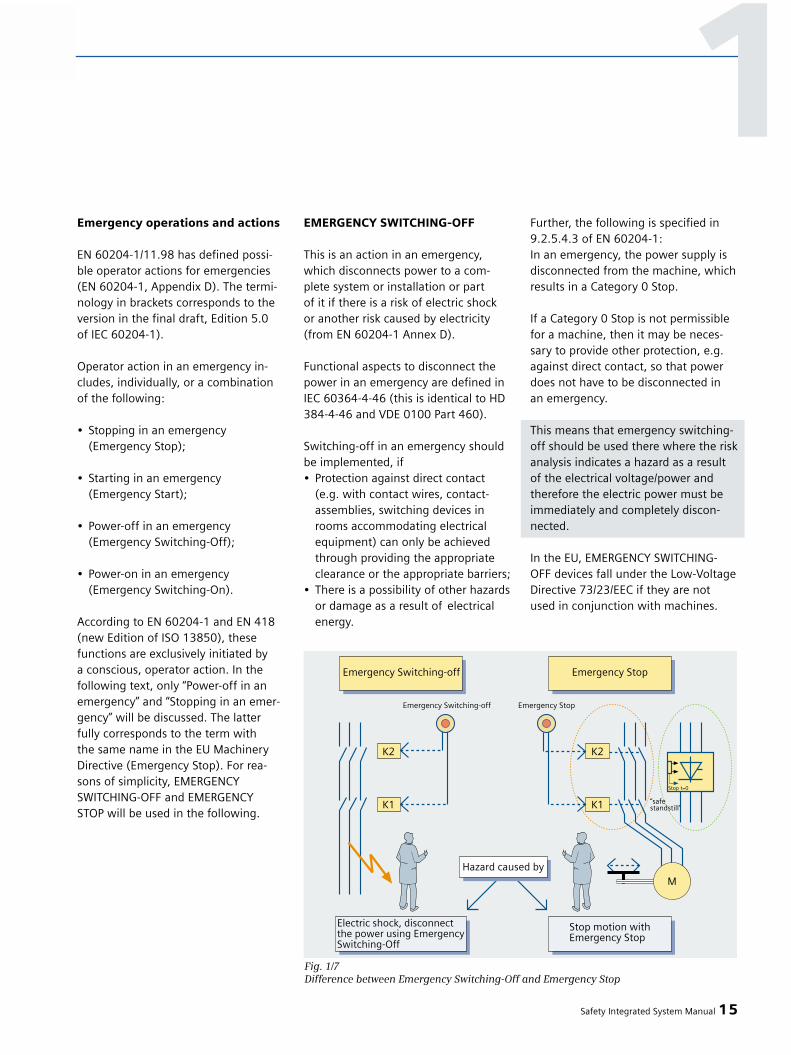
EMERGENCY SWITCHING-OFF
This is an action in an emergency,which disconnects power to a com-plete system or installation or part of it if there is a risk of electric shock or another risk caused by electricity(from EN 60204-1 Annex D).
Functional aspects to disconnect thepower in an emergency are defined inIEC 60364-4-46 (this is identical to HD384-4-46 and VDE 0100 Part 460).
Switching-off in an emergency shouldbe implemented, if• Protection against direct contact
(e.g. with contact wires, contact-assemblies, switching devices inrooms accommodating electrical equipment) can only be achieved through providing the appropriate clearance or the appropriate barriers;
• There is a possibility of other hazardsor damage as a result of electrical energy.
Further, the following is specified in9.2.5.4.3 of EN 60204-1:In an emergency, the power supply isdisconnected from the machine, whichresults in a Category 0 Stop.
If a Category 0 Stop is not permissiblefor a machine, then it may be neces-sary to provide other protection, e.g.against direct contact, so that powerdoes not have to be disconnected in an emergency.
This means that emergency switching-off should be used there where the riskanalysis indicates a hazard as a resultof the electrical voltage/power andtherefore the electric power must beimmediately and completely discon-nected.
In the EU, EMERGENCY SWITCHING-OFF devices fall under the Low-VoltageDirective 73/23/EEC if they are notused in conjunction with machines.
Safety Integrated System Manual 15
Fig. 1/7Difference between Emergency Switching-Off and Emergency Stop
1
If they are used in conjunction withmachines, then just like all of otherelectrical equipment of the machine,they also come under the MachineryDirective 98/37/EC.
Emergency Stop
This is an action in an emergency,which is defined to stop a process ormovement which would otherwisehave potentially hazardous conse-quences (from EN 60204-1 Annex D).Further, the following is defined in9.2.5.4.2 of EN 60204-1:
Stopping
In addition to the requirements forStop (refer to 9.2.5.3), the followingrequirements apply for an EmergencyStop:
• This must have priority over all otherfunctions and operator actions in all operating modes;
• The power to the machine driveelements, that could result in apotentially hazardous conditionor potentially hazardous conditions,must be disconnected as quickly as possible without creating other hazards(e.g. using mechanical stop-ping devices, that do not requirean external supply, using counter-current braking for stop Category 1);
• A reset may not initiate a restart.
Stopping in an emergency must eitherbe effective as a Category 0 orCategory 1 stop (refer to 9.2.2).
The stop Category in an emergencymust be defined as the result of therisk evaluation for the particularmachine.
To technically implement EmergencyStop corresponding to the recommend-ed application in the Foreword of EN60204-1, either the requirements spec-ified in EN 60204-1 or in EN 954 andIEC 61508 can be applied. EN 60204-1Edition 4 specifies the implementationpredominantly using electromechani-cal components. The reason for this is that “basic” (pro-grammable) electronic systems are notsufficiently safe. By correctly applyingEN 954 - and if required IEC 61508 -electronic and programmable electron-ic components are functionally safe sothat they can also be used to imple-ment an Emergency Stop function forall categories.
The Emergency Stop function specifica-tions will be updated with Edition 5(this is expected in 2005). In the finaldraft of 2004 (the final Edition was stillnot available at the time that this doc-ument when to print) the followingstatement applies:
The Emergency Stop shall functioneither as a Category 0 stop or as aCategory 1 stop (see 9.2.2). The choiceof the category of the Emergency Stopdepends on the results of a risk assess-ment of the machine.
In addition to the requirements forstop (see 9.2.5.3), the Emergency Stopfunction has the following require-ments:
• It shall override all other functions and operations in all modes;
• Power to the machine actuators that can cause a hazardous condi-tion(s) shall be either removed immediately (stop Category 0) or shall be controlled in such a way to stop the hazardous motion as quickly as possible (stop Category 1)without creating other hazards;
• Reset shall not initiate a restart.
This new formulation means that thereare no longer any restrictions statingthat hard-wired, electromechanicalequipment must be used to implementsafety-related functions.
Devices for EMERGENCY SWITCH-ING-OFF and EMERGENCY STOP
Devices that are used to stop equip-ment and machinery in an emergencymust be provided at every operatorcontrol location and also at other loca-tions where it may be necessary to ini-tiate a stop in an emergency (excep-tion: operator control stations whichare not connected through cables).
In order to fulfill the protective goals,specified in EN 60204-1 as well as EN418, the following requirements applyfor both functions (also refer to 10.7 in EN 60204-1):
• When the contacts switch, even whenbriefly actuated, the command devicemust positively latch.
• It is not permissible that the machinecan be restarted from a remote mainoperator station without the hazard having first been removed. The emer-gency switching command must be released locally in the form of a con-scious operator action.
16 Safety Integrated System Manual
1 – Regulations and Standards
Wireless operator control stations musthave their own function - that can alsobe clearly identified - to initiate amachine stop. The operator controlstation that initiates this stop functionmay neither be marked nor labeled asa device for emergency stopping.
Implementing safety-related func-tions
When implementing safety-relatedcontrol functions, the requirements of ISO 13849 (EN 954) and IEC 62061(IEC 61508) must be complied withcorresponding to the specified riskreduction. When the requirements of these standards are taken intoaccount, it is possible, to even imple-ment complex functions by usingelectronic and programmable elec-tronic systems, for example, a fail-safeSIMATIC or SINUMERIK. These func-tions can then be implemented in asafety-related fashion.
Man-machine (color coding foroperator control devices and dis-plays)
In order to simplify the interactionbetween man and machine, StandardsEN 60073 and DIN EN 60204 specifythe appropriate coding.
Switches, pushbuttons and signalinglamps are predominantly used as theinterface between man and themachine. These operator control ele-ments are clearly identified
and coded using colors that areassigned a very specific significance.This guarantees that the degree ofsafety for the operating personnel is increased and it is also simpler tooperate and service the equipment/systems.
The colors of pushbuttons, the signifi-cance of these colors, explanationsand application examples are shown in Fig. 1/8.According to DIN EN 60204-1 (VDE0113 Part 1) the following has to beobserved:
WHITE, GREY or BLACK are the colorsthat can be used for START/ON opera-tor command devices - preferablyWHITE. GREEN may be used, RED maynot be used.
RED must be used for EmergencySwitching-Off and Emergency Stopcommand devices.
The colors for STOP/OFF operator con-trol devices should be BLACK, GREY orWHITE - preferably BLACK. RED is alsopermitted. It is not permissible to useGREEN.
WHITE, GREY and BLACK are the pre-ferred colors for pushbuttons, whichcan be used alternating as START/ONand STOP/OFF pushbuttons. It is notpermissible to use RED, YELLOW orGREEN.
WHITE, GREY and BLACK are thepreferred colors for pushbutton com-mand devices that result in an operat-ing sequence while they are actuatedand operation is terminated if they arereleased (e.g. jogging).
It is not permissible to use RED,YELLOW or GREEN.
GREEN is reserved for functions thatdisplay a safe or normal operating con-dition.
YELLOW is reserved for functions thatdisplay an alarm or a non-standard(abnormal) condition.
BLUE is reserved for functions thatrequire a specific action.
Reset pushbuttons must be BLUE,WHITE, GREY or BLACK. If they also act as STOP/OFF pushbuttons, WHITE,GREY or BLACK are permissible - butpreferably BLACK. It is not permissibleto use GREEN.
If the same color - white, grey or black- is used for various functions (e.g.white for start/on and stop/off actuator), additional coding means (e.g. in theform of shape, position, symbol) mustbe used for identification purposes.
The colors of the indicating lamps,their significance with reference to thestatus of the machine as well as theirhandling and application examples arelisted in Fig. 1/9.
For illuminated pushbuttons, the in-formation in Figs. 1/8 and 1/9 applies. If problems are encountered whenassigning suitable colors, then thecolor WHITE must be used. For Emergency Switching-Off devices,the color RED may not depend on theillumination.
Safety Integrated System Manual 17
1

18 Safety Integrated System Manual
1 – Regulations and Standards
Color Meaning Explanation Examples of application
RED Emergency Actuate in the event EMERGENCY STOP,of a hazardous condi- Initiation of EMERGENCY STOP functions,tion or emergency conditional for STOP/OFF
YELLOW Abnormal Actuate in the Intervention to suppress an abnormalevent of an condition,abnormal Intervention to restart an interruptedcondition automatic cycle
GREEN Normal Actuate to START/ON,initiate normal however WHITE should be conditions or preferably usednormal status
BLUE Mandatory Actuate for a Reset functioncondition requiringmandatory action
WHITE No specific For general START/ON (preferred),meaning initiation of functions STOP/OFFassigned except for
GREY EMERGENCY STOP START/ON,(see STOP/OFFnote)
BLACK START/ON,STOP/OFF (preferred)
Comment: Where a supplemental means of coding (e. g. shape, position, texture) is used for the identification of pushbutton actuators, then the same color WHITE, GREY or BLACK may be used for various functions , e. g. WHITE for START/ON and for STOP/OFF actuators.
Color Meaning Explanation Action by Examples ofoperator application
RED Emergency Hazardous Immediate action, Pressure/condition to deal with a temperature outside
hazardous condition safe limits,(e. g. by operating voltage drop,EMERGENCY STOP) voltage interrupted,
passing through a stop position
YELLOW Abnormal Abnormal condition Monitoring and/ Pressure/temperatureimpending or intervention outside normalcritical condition (e. g. by re-estab- operating ranges,
lishing the intended tripping a protectivefunction) device
GREEN Normal Normal condition Optional Pressure/temperaturewithin the normal operating ranges, permissive signal to continue
BLUE Mandatory Indication of a Mandatory Prompt to condition that action enter specifiedrequires action by valuesthe operator
WHITE Neutral Other conditions: Monitoring Generalmay be used informationwhenever doubt exists about the application of RED, YELLOW, GREENor BLUE
Fig. 1/8Colors for pushbuttons and their significance according to EN 60204-1 (VDE 0113 Part 1): 06.93
Fig. 1/9
Colors for indicator lights and
their significance acc. to EN 60204-1
(VDE 0113 Part 1): 06.93

Coding cables
The color coding of switches, push-buttons and indicator lamps has beendiscussed in the previous Section. EN60204 offers a higher degree of flexi-bility when coding cables. It specifiesthat “... cables at every connectionmust be able to be identified in confor-mance with the technical documenta-tion...” .
The numbering of terminals matchingthe circuit diagram is sufficient if it ispossible to visually trace the cable. Forcomplex controls, we recommend thatthe internal cables used for wiring aswell as the outgoing cables are codedso that after the cable has been dis-connected from the terminal it can be easily reconnected to the same ter-minal. This is also recommended forterminal locations which have to bedisconnected when the equipment istransported.
Using the formulation in IEC 60204-11997, Paragraph 14.2.1 conductorcoding/identification, the StandardsCommittee wanted to make the follow-ing statement:
1.Each individual conductor must beable to be identified, however, only in conjunction with the documenta-tion. It is not necessary that every cable must be able to be identifiedwithout the appropriate documenta-tion.
2.The manufacturer and the operating company should agree on the type of coding and therefore also the identification techniques.
It is not the intention of the Standardto specify a certain coding type that isworldwide. For instance, for safety reasons, facto-ry-internal specifications may have ahigher priority in order to avoid confu-sion in specific areas that are handledby the same personnel. These defini-tions cannot be generalized due to the wide application range of the par-ticular Standard - from small individualmachines (high unit volume standardproducts) up to large, complex plants(with unique equipment and systems).
Primarily, appropriate testing should be used to avoid installation/assemblyfaults.
A standard color coding for the cablesshould be used. We recommend thefollowing color assignment:
• Black formain AC and DC current circuits
• Red for AC control circuits
• Blue for DC control circuits
• Orange forinterlocking circuits that aresupplied from an externalpower source.
The above color assignment is recom-mended if a decision is made to justuse color coding. The only mandatoryspecification is the color coding of theprotective conductor and the neutralconductor. For all other cabling andwiring, one of the methods listed in14.2.4 can be selected (color, numbersor letters; or a combination of colorsand numbers or colors and letters).
Protective conductor marking
The protective conductor must be ableto be uniquely identified as a result ofits shape, location, coding or color. If itis only identified as a result of its color,then a two color-combination of green/yellow must be used along the wholelength of the cable. The green/yellowcolor may only be used for protectiveconductors.
Neutral conductor marking
If a circuit has a color-coded neutralconductor, then light blue must beused. Light blue may not be used tocode other cables if there is a dangerof accidentally interchanging them.
If a neutral conductor is not used, alight-blue conductor may be used forother purposes, but not as protectiveconductor.
Safety Integrated System Manual 19
1
Process technology in Europe
Legislative requirements in Europe
The following EU Directives must beessentially applied for process tech-nology:
• Directive 96/82/EC of the Council from the 9th December 96 to con-trol hazards when critical accidents occur with hazardous substances (“Seveso Guideline ” II).
• Low-Voltage Directive
• Machinery Directive (98/37/EC)
• Pressure Equipment Directive (97/23/EC). It is only relevant as the equipment used must fulfill this directive. “The Directive onthe other hand is not valid forthe assembly of pressurizedequipment that is located on theuser's grounds, for example, in industrial plants, under his respon-sibility.”
At the same time, the Health and Safetyat Work and Accident Prevention Regu-lations must always be carefully obser-ved and adhered to.
“Seveso Directive”
An important component of this EUDirective is the fact that companies are responsible in setting-up andimplementing a safety managementsystem. This must include an in-depthrisk assessment, taking into account all of the possible accident scenarios. It specifies, corresponding to the prin-ciples explained in the Introduction,the safety objective,
⇒ using preventive measurementsto maintain the quality of the environment and ensure the health and safety of people."
In order to achieve this goal, the fol-lowing basic requirements have beendrawn-up. The Member States mustensure that these are fulfilled.
⇒ Concept to avoidsevere accidents
The owner/operating company is res-ponsible for “… drawing-up a docu-ment setting-out his major accidentprevention policy and appropriatesteps to ensure that it is properlyimplemented. A high degree of pro-tection for man and the environmentshould be ensured using a conceptimplemented by the operating com-pany to avoid severe accidents byusing suitable measures, organizationand management systems” (Article 7Paragraph 1).
The document must also take intoaccount the following basic principles:
• The concept to avoid severe accidentsmust be drawn-up in writing.
• A safety management system, in which, among others, the followingpoints are regualted:
– Determine and evaluate the risks –determine and use methods and techniques to systematically iden-tify risks.
– Operational checking – determineand use methods and techniquesfor safety-related operation, inclu-ding the service&maintenance of plants and systems.
– Quality assurance – determine anduse methods and techniques to continually evaluate and ensure that goals and objectives are achieved.
⇒ Safety report
The operating company is responsiblein drawing-up a safety report in whichthe following is shown
• That a concept was implemented,
• That the hazards have been deter-mined and all of the required mea-sures have been applied to avoid such accidents and to limit the con-sequences for both man and the environment, and
• Design, construction as well as the operation of all plants and systemsis sufficiently safe and reliable.
⇒ Inspection
The regulatory bodies must set up asystem of inspections to systematicallycheck the operational, organizationaland management-specific systems ofthe operation which will allow theseregulatory bodes to confirm that theuser/operating company can prove
• That it has taken all of the requiredmeasures to avoid severe accidents,and has provided
• Adequate measures to limit the consequences.
20 Safety Integrated System Manual
1 – Regulations and Standards

This EU Directive must be nationallyimplemented. In Germany this is implementedin the “Störfallverordnung” [regulationthat handles responses and escalationstages when an accident occurs].
Note: The “Seveso Directive” is not aDirective of the “New Approach”, i.e.the principle that when harmonizedstandards are applied, it can be auto-matically assumed that the objectivesof the Directive are fulfilled, does notapply here. The exact requirements are regulated at a domestic level.
Plants and systems where these regula-tions apply - after a new plant has beenconstructed or significant changes havebeen made - must be checked by theappropriate regulatory body beforecommissioning takes place to ensurethat state-of-the-art technology hasbeen applied regarding the fulfillmentof the safety goals. The assessment isbased on the relevant standards.
Technical measures to fulfill leg-islative goals
The first priority is to design the processso that it is inherently safe. Where thisis not possible, additional measures arerequired to reduce the remaining riskto an acceptable level. Process controltechnology (PLT) systems can be used
to achieve this under the clear condi-tion that they are suitable for the spe-cific task. Electronic controllers aresuitable for securing the safety of theplant if they have been specificallydesigned for this purpose. The require-ments are described in the Standards.
Relevant Standards for safetymeasures using basic processcontrol technology
For safety measures using basic processcontrol technology - up until now thefollowing domestic standards havebeen applied:
After the IEC 61508 was ratified inEurope as EN 61508, in September2004 the domestic standards were no longer valid. Instead, EN 61508must now be applied. The specificstandard for the process industry is IEC 61511 “Functional safety: Safetyinstrumented systems for the processindustry sector”. IEC 61511 defines therequirements of EN/IEC 61508, specifi-cally for the process industry. At theend of 2004, it can be expected that it will be ratified as EN 61511.
Beyond this, additional Standards applyfor the devices and equipment used.These Standards involve the specificsafety requirements. Also refer toChapter Safety of Machinery (refer to Chapter 1.2).
In Germany, there is the VDI/VDE 2180Directive “Ensuring the safety of processplants using process control technolo-gy”, for practically implementing plantand system safety. This describes therequirements of the relevant Standardin a simplified form. The new Editionof VDI/VDE 2180 takes into accountIEC 61511 and also includes the require-ments from NE 31 “Securing plant safe-ty using process control technology”and NE 79: “Micro-processor-basedequipment in plant safety systems”.
This document is used as a practicalguideline. When it comes to selectingsafety-related PLCs and other micro-processor-based components (e.g.transmitters), the two standards men-tioned above offer a different perspec-tive than the User Directives and whenrequired, should also be taken intoaccount.
Safety Integrated System Manual 21
1

Reducing risks using basic processcontrol technology
Measures are required to reduce risks if faults or disturbances in the basicprocess control system and monitoringdevices can lead to a dangerous eventor can cause the system to go into ahazardous condition and if the result-ing risk is unacceptably high. In thiscase, suitable protective measuresmust be taken, either to sufficientlyreduce the probability of a hazardousevent occurring or to reduce the extentof the damage. This can be achievedusing basic process control protectiveequipment and systems if these fulfillthe safety requirements.
Risk reduction
As it is not possible to completelyexclude certain risks - both from atechnical and economic standpoint - it is necessary not only to determinethe existing risk, but also to define and specify a risk that can be tolerated.The measure for the safety integrity of the risk-reducing functions is thenderived from the difference betweenthese two factors. EN 61508 defines“Safety Integrity Level” (SIL) as a targetmeasure for the probability of failurewhen executing risk-reducing functions.For safety-related systems in the processindustry that operate in the require-ment mode, this measure is defined in IEC 61511 as risk reduction factor.
22 Safety Integrated System Manual
1 – Regulations and Standards
Fig. 1/10
Positioning of process control systems in safety-related/non-safety-related configurations
Fig. 1/11Principle of risk reduction (acc. to IEC 61508)

Selecting the equipmentand basics of the requiredfeatures
Safety function
Risk reduction using electronic con-trollers is realized by defining functionsfor each possible dangerous event oreach possible dangerous condition ofthe plant or system that prevent thedangerous event occurring. These so-called “safety functions” are used toensure that the plant/system remainsin a safe condition or a safe conditionis restored if there is a threat of a hazardous event due to a fault or a disturbance in the plant or system. The safety function can also be used to reduce the extent of any damagedue to a hazardous event.
The definition of a safety functionalways includes the specification of the function itself (e.g. shutting-off the feed to a container if the level hasreached its maximum level) and the“Safety Integrity (SIL)” derived from the risk analysis.
Implementing the safety functions
Every safety function always encom-passes the complete chain - from theinformation acquisition through infor-mation evaluation up to executing thespecific action.
The equipment involved, for example,fail-safe PLCs, sensors and actuatorsetc. must fulfill, as a total, the deter-mined SIL. If a device is used for vari-ous safety functions at the same time,then it must fulfill the highest SIL ofthe individual functions.
Device characteristics and features
If PLCs are used to process informationand data, then these, as “Safety PLC”(SPLC) must fulfill the requirements ofthe relevant standards (e.g. IEC 61508),corresponding to the specified SIL.Further, they should be certified by anindependent testing organization. Theessential characteristics and features offail-safe PLC, that are specified in a gra-duated scope in the Standards, include:
• In the development, manufactureand service&maintenance, certainmeasures and techniques must be used, therefore avoiding systematicfaults.
• The PLC must be able to control systematic faults that occur in operation.
• The PLC must be able to detect and control random hardware failures in operation.
• Fault control means that when the system detects a fault it must reliablyexecute the safety function defined for this particular case (e.g. shutdownthe plant or system).
Similar requirements also apply forcomplex field devices. Details on thisare described in IEC 61511.
Safety Integrated System Manual 23
Fig.1/12
Safety Integrity levels according to IEC 61508: Target measure for the failure of a
safety function, allocated to a safety-related system
Fig. 1/13
Evaluation unit, e.g. safety PLC
Safety High demand or continuous Low demand mode of operationIIntegrity mode of operationLevel (probability of a (average probability of failure to perform
dangerous failure per hour) its design function on demand)
4 ≥ 10-9 to < 10-8 ≥ 10-5 to < 10-4
3 ≥ 10-8 to < 10-7 ≥ 10-4 to < 10-3
2 ≥ 10-7 to < 10-6 ≥ 10-3 to < 10-2
1 ≥ 10-6 to < 10-5 ≥ 10-2 to < 10-1
1

Application
When using a fail-safe PLC, the condi-tions, defined in the associated safetymanual must be carefully compliedwith and any additional requirementsassociated with the certificate.
For the peripheral devices to be con-nected (e.g. sensors and actuators), inaddition, the requirements listed in theStandards (IEC 61508 and IEC 61511)must be carefully observed regardingthe following aspects:
• Avoiding systematic faults such as,e.g. configuring/engineering,installation and handling faults.
• Detecting and controlling random faults (failures).
• Necessary fault tolerance. Thisdepends on the percentage of the failures that fail in the safedirection.
• Required service & maintenance(repeated tests and checks).
IEC 61511 limits the maximum permis-sible SIL for which the field devicesmay be used, depending on their faulttolerance. The fault tolerance, shownin Fig. 1/14 can be reduced by 1, if:
• The devices have been well-proven in operation,
• The devices only allow the setting of process-related parameters, and
• The setting of process-relatedparameters is protected.
In order to achieve the higher hard-ware fault tolerance necessary toachieve the SIL level for specific appli-cations, field devices can be redun-dantly used - as long as the devices aresuitable for this SIL as far as their otherfeatures and characteristics are con-cerned.
Test and monitoring functions can beintegrated in the PLC in order to detectfaults in the peripheral devices (I/Odevices). A response that may be
required must be performed within asuitably short time.
These time requirements depend onthe fault tolerance. The precise require-ments are defined in IEC 61511.
When using more complex peripheraldevices (e.g. transmitter with micro-processor), it must be ensured thatthese devices themselves are in com-pliance with the relevant Standards(EN 61508 and IEC 61511).
The complete basic process controlprotective system must be configuredso that it fulfills the relevant standardsfor all of the safety-related functions.Regarding functional safety, these areEN 61508 and IEC 61511.
24 Safety Integrated System Manual
1 – Regulations and Standards
Fig. 1/14Maximum permissible SIL for field devices dependent on their fault tolerance(acc. to IEC 61511-1)
SIL Minimum hardware fault tolerance if the main failure direction is towards the safe condition
1 0
2 1
3 2
Note: Those failures are designated as “safe” where a safe plant condition is maintained.Note: A fault tolerance of N means that N+1 faults cause the function to fail.
Furnace systems in Europe
EU Directives
Furnaces and burners must fulfill therelevant Directives as a result of theirapplication and the devices and equip-ment which are used (e.g. MachineryDirective, Pressured Equipment Direc-tive (...), Directive for Gas Burners(90/396/EEC)). There are no specific EU Directives for furnace systems.Furnaces are subject, where relevant,to application-specific Directives.Industrial thermo-processing equip-ment is, for example, classified asmachinery under the MachineryDirective.
Standards
Industrial thermo-processingequipment and systems
The European series of standards EN 746-x “Industrial thermo-processsystems …”, apply for these types ofplants and systems; these Standardsare harmonized under the MachineryDirective.
EN 746 can be applied to industrialthermal-processing equipment, forexample
• Plants that produce and finishmetal,
• Glassworks,
• Ceramic plants,
• Cement, lime and gypsum plants,
• Chemical plants,
• Incinerators etc.
Part 1: “General safety requirementsfor industrial thermo-process plants”makes reference to EN 60204-1 andEN 954-1 for the implementation ofthe electrical equipment.
Furnaces
The following is applicable as generalstandard for furnace systems that donot belong to the industrial thermal-process systems and are not used toheat process fluids and gases in thechemical industry:
• EN 50156 “Electrical equipment for furnaces Part 1: Requirements for application design and installation”
The German Standard DIN VDE 0116“Electrical equipment for furnacesystems”. EN 50156 specifies that EN 60204-1 must be complied with.The requirements for safety relevantsystems is based on IEC 61508.
The following standards are presentlyin force for burners
• EN 676 gas burners;
• EN 230 oil vaporization burners in amono-block design;
• EN 267 oil burners;
• EN 298 automatic furnace systemsfor gas burners and gas devices with and without blower.
Safety Integrated System Manual 25
1

Note: The following description isintended to provide an overview of theprinciples and basic requirements. Itshould not be considered as a com-plete description of the situation. Thereader of this document must, in addi-tion, inform himself about the preciserequirements as well as the domesticand local regulations for his particularapplication.
An essential difference between thelegislation associated with safety atwork between North America andEurope is the fact that in the US thereis no standard legislation regardingmachinery safety that addresses theresponsibility of the manufacturer/sup-plier. There is a general requirementthat the employer must provide a safeplace of work.
US - general
The Occupational Safety and HealthAct (OSHA) from 1970 is responsible in regulating the requirements foremployers to ensure safe workingconditions. The core requirements of OSHA are listed in Section 5“Duties”:
(a) Each employer -(1) shall furnish to each of his em-
ployees employment and a place of employment which are free from recognized hazards that are causing or are likely to cause death or serious physical harm to his employees;
(2) shall comply with occupational safety and health standards promulgated under this Act.
The requirements from the OSH Actare administered and managed by the Occupational Safety and HealthAdministration (also called OSHA).OSHA deploys regional inspectors whocheck whether workplaces (places of employment) fulfill the applicableregulations.
The regulations, relevant for safety at work of the OSHA are defined anddescribed in OSHA 29 CFR 1910.xxx(“OSHA Regulations (29 CFR) PART1910 Occupational Safety and Health”).(CFR: Code of Federal Regulations).
Also refer to www.osha.gov.
The following is stated at the begin-ning of the regulations for the Safetyand Health Program (29 CFR 1900.1):
“(b)(1) What are the employer's basic obligations under the rule? Each employer must set up a safety and health program to manage workplace safety and health to reduce injuries, ill-nesses and fatalities by system-atically achieving compliance with OSHA standards and the General Duty Clause.”
And later
"(e) Hazard prevention and control.
(e)(1) What is the employer's basic obligation? The employer's basic obligation is to systema-tically comply with the hazard prevention and control require-ments of the General Duty Clause and OSHA standards.
(e)(2) If it is not possible for the employer to comply immedi-ately, what must the employer do? The employer must developa plan for coming into compli-ance as promptly as possible, which includes setting prioritiesand deadlines and tracking progress in controlling hazards. Note: Any hazard identified by the employer's hazard identifi-cation and assessment process that is covered by an OSHA standard or the General Duty Clause must be controlled as required by that standard or that clause, as appropriate."
The application and use of variousStandards is regulated in 29 CFR1910.5 “Applicability of standards.” The concept is similar to that inEurope. Product-specific standardshave priority over general standards as long as the associated aspects areactually handled there. When the stan-dards are fulfilled, the employer canassume that he has fulfilled the corerequirements of the OSH Act regardingthe aspects actually handled in thestandard.
1910.5 (f) “An employer who is in compliance with any standard in this part shall be deemed to be in com-pliance with the require-ment of section 5(a)(1) of the Act, but only to the extent of the condition, practice, means, method, operation, or process covered by the standard.”
26 Safety Integrated System Manual
1 – Regulations and Standards
1.3 Legal requirementsand standards regardingsafety at work in NorthAmerica
Machine safety
Minimum requirements of the OSHA
The OSHA Regulations under 29 CFR1910 include general requirements formachines and machinery (1910.121)and a series of specific requirementsfor certain types of machines. Therequirements specified are extremelyspecific but have little technical detail.Excerpt from 29 CFR 1910.212 “Generalrequirements for all machines”:
"(a)(1)
Types of guarding. One or more meth-ods of machine guarding shall be pro-vided to protect the operator and otheremployees in the machine area fromhazards such as those created by pointof operation, ingoing nip points, rotat-ing parts, flying chips and sparks.Examples of guarding methods are bar-rier guards, two-hand tripping devices,electronic safety devices, etc.“ An exam-ple of the requirements for the controlof presses is the following excerpt from29 CFR 1910.217 ”Mechanical PowerPresses":
"(b)(13)
Control reliability. When required byparagraph (c)(5) of this section, thecontrol system shall be constructed sothat a failure within the system doesnot prevent the normal stopping actionfrom being applied to the press whenrequired, but does prevent initiation ofa successive stroke until the failure iscorrected. The failure shall be detectableby a simple test, or indicated by thecontrol system. This requirement doesnot apply to those elements of the con-trol system which have no effect on theprotection against point of operationinjuries."
"(h)(6)(xvii)
Controls with internally stored programs(e.g., mechanical, electro-mechanical,or electronic) shall meet the require-ments of paragraph (b)(13) of thissection, and shall default to a predeter-mined safe condition in the event ofany single failure within the system.Programmable controllers which meetthe requirements for controls withinternally stored programs statedabove shall be permitted only if alllogic elements affecting the safety sys-tem and point of operation safety areinternally stored and protected in sucha manner that they cannot be alteredor manipulated by the user to anunsafe condition."
The OSHA regulations define minimumrequirements to guarantee safe placesof employment. However, they shouldnot prevent employers from applyinginnovative methods and techniques,e.g. “state of the art” protective sys-tems in order to maximize the safety of employees (refer to e.g.: www.osha.gov/ ...Stan-dard Interpretations ... 06/05/2001 -Use of Electro Sensitive ProtectionEquipment ...)
In conjunction with specific applica-tions, OSHA specifies that all electricalequipment used to protect employees,must be certified for the intendedapplication by a nationally recognizedtesting laboratory (NRTL) authorized byOSHA (refer to e.g.: www.osha.gov/...Standard Interpretations ...08/11/1994 - Presence sensing devices(PSDs) for power presses.: “...OSHArequires that all electrical productsused by employees must be treatedand approved for their intended use byan OSHA Approved Nationally Recog-nized Testing Laboratory (NRTL)....”).
Application and use of additionalstandards
In addition to OSHA Regulations, it isjust as important to carefully observethe current standards of organizationssuch as NFPA and ANSI as well as theextensive product liability legislationwhich is in force in the US. As a resultof the product liability, it is in the inter-est of manufacturers and operatingcompanies to carefully observe andmaintain the regulations - and they are more or less forced to fulfill thestate-of-the-art technology require-ment".
Third-party insurance contracts gener-ally demand that the parties fulfill theapplicable standards of the standardi-zation organizations. Companies whoare self-insured initially do not havethis requirement. However, in the caseof an accident, they must prove thatthey had applied generally recognizedsafety principles.
NPFA 70 (known as the NationalElectric Code (NEC)) and NFPA 79(Electrical Standard for IndustrialMachinery) are two especially impor-tant standards regarding safety inindustry. Both of these describe thebasic requirements placed on the fea-tures and the implementation of elec-trical equipment. The National ElectricCode (NFPA 70) predominantly appliesto buildings, but also to the electricalconnections of machines and parts ofmachines. NFPA 79 applies to machines.This results in a grey area (somewhatundefined) in the demarcation betweenboth standards for large machines andmachinery that comprise partial ma-chines. For instance, large conveyorsystems can be considered to be partof the building so that NFPA 70 and/orNFPA 79 should be applied.
Safety Integrated System Manual 27
1
NFPA 79
This Standard applies to the electricalequipment of industrial machines withrated voltages less than 600 V (a groupof machines that operate together in a coordinated fashion is considered asa machine).The new Edition NFPA 79 - 2002includes basic requirements for pro-grammable electronics and fieldbusesif these are used to implement safety-related functions. When these require-ments are fulfilled, specifically quali-fied electronic controls and fieldbusesmay only be used for Emergency Stopfunctions, stop Categories 0 and 1(refer to NFPA 79 - 2002 9.2.5.4.1.4).Contrary to EN 60204-1, NFPA 79specifies that for Emergency Stop func-tions the electrical power must be dis-connected using electromechanicaldevices.
The core requirements placed on programmable electronics and busesinclude:System requirements(refer to NFPA 79 - 2002 9.4.3)
• Control systems that containsoftware-based controllers must, (1) if a single fault occurs, bring
the system into a safe condition so that it can be shut down
- prevent restarting until thefault has been removed
- prevent unexpected starting
(2) offer protection that is compara-ble to hard-wired controls
(3) be implemented to correspond to a recognized Standard that defines the requirements for such systems
In a Note, it is stated thatIEC 61508 is a suitable standard.
Requirements placed on programma-ble equipment (refer to NFPA 79 -2002 11.3.4)
• Software and firmware-based controllers that are used in safety-relevant functions must be listed for such an application (i.e. certified by an NRTL).
In a note, it is stated thatIEC 61508 provides requirementsfor the design of such a controller.
Listing files of electronic devicesfor safety-related functions
In order to implement the requirementsin NFPA 79: 2002, UL has defined aspecial category for “ProgrammableSafety Controllers” (code NRGF). Thiscategory addresses control devices thatcontain software and are intended tobe used for safety-related functions.
A precise description of the categoriesas well as the list of the devices thatfulfill these requirements is provided in the Internet:
www.ul.com –> certifications directory–> UL Category code / Guide informa-tion –> search for category “NRGF”
TUV Rheinland of North America, Inc.is also an NRTL for these applications.The products listed there can also becalled-up in the Internet: With the “ID”of the device (Enter TUVdotCOM ID),the description, entered in the listing,can be called from the products listedthere. (http://www.tuv.com.
URL: http://www.tuv.com
ANSI B11
The ANSI B11 Standards are consensusStandards, that have been developedby associations - e.g. the Associationfor Manufacturing Technology (AMT),National Fire Protection Association(NFPA) and the Robotic IndustriesAssociation (RIA)for various types ofmachine tools.
The potential hazards of a particularmachine are assessed using the riskanalysis. Risk analysis is an importantrequirement according to NFPA79-2002, ANSI/RIA 15.06 1999, ANSIB11.TR-3 and SEMI S10 (semiconduc-tors). A suitable safety technology/system can be selected using the docu-mented results of a risk analysis - basedon the specified safety class of the par-ticular application.
ANSI B11.TR-4 was approved in 2004for the application of programmableelectronic systems for the safety ratedfunctions of machines covered by theB11 series. This Technical Referencerefers to NFPA 79: 2002 and providesguidance for the application of safetyPLC technology for the safety ratedfunctions identified by the RiskAnalysis.
The current list of ANSI Standards isprovided below. This list is intended asa reference and if an authorized revisionis to replace these, then the revisedStandard applies.
28 Safety Integrated System Manual
1 – Regulations and Standards
General perspectives
ANSI B11.TR-1 (1993)Ergonomic Guidelines for the design,installation and use of machine tools
ANSI B11.TR-2 (1997)Mist control considerations for thedesign, installation and use of machinetools using metalworking fluids
ANSI B11.TR-3 (2000)Risk assessment and risk reduction – Aguide to estimate, evaluate and reducerisks associated with machine tools
ANSI B11.TR-4 Application of programmable electron-ic systems for the safety related func-tions of machines covered by the B11safety standard series
ANSI Z244.1 (2003)Control of hazardous energy- Lockout/tagout and alternative methods
ANSI Z535.1 (2002)Safety Color Code
ANSI Z535.3 (2002)Criteria for Safety Symbols
ANSI Z535.4 (2002)Product Safety Signs and Labels
ANSI Z535.5 (2002)Accident Prevention Tags and Labels
Additional reference standardswith special definitions and addi-tional information:
OSHA 29CFR 1910.147Control of hazardous energy (“lockout/tagout”)
IEC 61496 (2003)Safety of machinery; Electrosensitiveprotective equipment
Standards for the particularmachine type
ANSI B11.1 (2001)Safety requirements for MechanicalPower Presses
ANSI B11.2 (1995)Safety requirements for HydraulicPower Presses
ANSI B11.3 (2002)Safety requirements for Power PressBrakes
ANSI B11.4 (2003)Safety requirements for Shears
ANSI B11.5 (2002)Iron Workers - Safety requirements for construction, care and use
ANSI B11.6 (2001)Safety Requirements for Manual TuningMachines
ANSI B11.7 (2000)Cold Headers and Cold Formers -Safety requirements for construction,care and use
ANSI B11.8 (2001)Safety requirements for Manual millingand boring Machines
ANSI B11.9 (1997)Grinding machines - Safety Requirementsfor Construction Care and Use
ANSI B11.10 (2003)Metal Sawing Machines - SafetyRequirements for Construction Careand Use
ANSI B 11.11 (2001)Safety Requirements for Gear & SplineCutting Machines
ANSI B11.12 (1996)Roll Forming and Roll Bendingmachines – Safety Requirements forConstruction Care and Use
ANSI B11.13 (1998)Automatic Screw/Bar and Chuckingmachines- Safety Requirements forConstruction Care and Use
ANSI B11.14 (1996)Coil Slitting Machines - SafetyRequirements for Construction Careand Use
ANSI B11.15 (2001)Safety Requirements for Pipe. Tube and Shape Bending Machines
ANSI B11.17 (1996)Horizontal Hydraulic Extrusion Presses -Safety Requirements for ConstructionCare and Use
ANSI B11.18 (1997)Coil Processing Systems - SafetyRequirements for Construction Careand Use
ANSI B11.19 (2003)Performance Criteria for Safeguarding
ANSI B11.20 (1996)Manufacturing systems / Cells - SafetyRequirements for Construction Careand Use
ANSI B11.21 (1997)MachineTools Using Lasers - Safety Requirements for Construction Careand Use
ANSI B11.22 (2002)Safety Requirements for NumericalControlled Turning Machines
ANSI B11.23 (2002)Safety Requirements la MachineCenters
ANSI B11.24 (2002)Safety Requirements for TransferMachines
Safety Integrated System Manual 29
1
Process industry in the US
The basic safety requirements of theOSHA for the process industry aredefined in OSHA's Process SafetyManagement of Highly HazardousChemicals, Explosives and BlastingAgents Standard (PSM), 29 CFR1910.119. (Refer to www.osha.gov ).
Excerpt from 29 CFR 1910.119:
Purpose. This section contains requirements for preventing or minimizing the consequences of catastrophic releases of toxic, reactive, flammable, or explosive chemicals. These releases may result in toxic, fire or explosion hazards.Section (d) with its sub-sectionscontain the basic requirementsplaced on process instrument-ation.
1910.119(d) Process safety information. ... the employer shall complete a compila-tion of written process safety infor-mation ... This process safety infor-mation shall include information pertaining to the hazards of the highly hazardous chemicals used or produced by the process, informa-tion pertaining to the technology of the process, and information pertaining to the equipment in the process.
1910.119(d)(3) Information pertaining to the equip-ment in the process.
1910.119(d)(3)(i)(F) Design codes and standards employed;
1910.119(d)(3)(ii) The employer shall document that equipment complies with recogni-zed and generally accepted good engineering practices.
OSHA provides guidelines on this with:CPL 2-2.45A "Process Safety Manage-ment of Highly Hazardous Chemicals-Compliance Guidelines and EnforcementProcedures.
OSHA specifies that the process instru-mentation must be implemented inaccordance with generally accepted“good engineering practice.” With a let-ter, dated March 2000, OSHA clarifiedan inquiry from ISA, that ANSI/ISA 84.01is a standard that is applicable nation-wide and which OSHA recognizes asgenerally accepted “good engineeringpractice.” However, in the same letter,OSHA clearly stated that ISA 84.01 isnot the only standard which is consid-ered when fulfilling the requirementsof 1910.119 (PSM).
CFR 1910.119 doesn't clearly statewhether the requirements refer to thecomplete instrumentation. Two typesof instrumentation are generally usedin the process industry. “Safety Instru-mented Systems” (SIS) and “BasicProcess Control System” (BPCS).ANSI/ISA 91.01 defines that only theSIS is to be handled under the OSHAregulations.
IEC 61511 “Functional safety: SafetyInstrumented Systems for the processindustry sector” is the IEC standard withthe same scope as ISA 84.01. It wasdeveloped, with significant involve-ment of the ISA and is to be includedin the new Edition of the ISA 84.
A large proportion of processes fallswithin the scope of ISA 84.01, butdoes not formally fall under 29 CFR1910.119 (PSM). Also in this case, theStandard should be applied in ordernot to violate the basic requirements of the “Duties” section of the Occupa-tional Safety and Health Act (OSHA).
30 Safety Integrated System Manual
1 – Regulations and Standards

Safety Regulations andStandards in Canada
Canada Labour Code is the law for all industries in Canada. Part 2 of theCanada Labor Law governs OccupationalHealth and Safety in the workplace.Under the Canadian constitution,labour legislation is primarily a provin-cial responsibility. The OccupationalHealth and Safety Act (OHSA) sets outthe rights and duties of all parties inthe workplace. Its main purpose is toprotect workers against health andsafety hazards on the job. The OHSAestablishes procedures for handlingrisks at the workplace and it providesfor enforcement of the law wherecompliance has not been achievedvoluntarily. Regulations issued underthe OSHA identify specific require-ments that must be complied with, set standards that must be met andprescribe procedures that must be fol-lowed to reduce the risk of accidents at work.
Officials appointed by the federal,provincial and territorial governmentshave the power to inspect workplacesand enforce the law by use of all en-forcement tools necessary, includingstop work orders, fines and prosecu-tions directed at the employers andworkers. These are for example Ministryof Labor (MoL) in Ontario or theCommission de la santé et de la sécu-rité du travail (CSST) in Quebec. Theofficials work closely with its agencies,
safe workplace associations (SWAs),worker training centers and clinics andthe Canadian Center for Health andSafety. Some of these key organiza-tions include Industrial Accident Pre-vention Association (IAPA) in Ontarioand The Institut de Reherche Robert-Sauvé en Santé et en Sécurité duTravail (IRSST) in Quebec. InsuranceBoards are also the key element inworkplace safety. For example, TheWorkplace Safety and Insurance Board(WSIB) oversees Ontario's workplacesafety education and training system,provides disability benefits by adminis-tering safety insurance program, moni-tors the quality of health care throughfinancial interventions etc.
Government of Canada, OccupationalHealth and Safety in Canada(www.hrsdc.gc.ca)
Ministry ofLabour(www.gov.on.ca/lab/)
Commission de la santé et de lasécurité du travail (www.csst.qc.ca)
Industrial Accident PreventionAssociation (www.iapa.on.ca)
The Institut de Recherche Robert-Sauvéen Santé et en Sécurité du Travail(www.irsst.qc.ca)
Workplace Safety and Insurance Board(www.wsib.on.ca)
The Regulation for Industrial Establish-ments under OHSA in Ontario, Regula-tion 528/00 Section 7 (PSHSR - PreStart Health and Safety Review) hasbeen in effect since the 7th of October2000. The 2nd item in the table is spe-cific to machinery safety. The employeris responsible for ensuring that allrequirements of the OHSA and the reg-ulations are complied with in the work-place. The regulation is, to a largeextent, a performance-based standard.This means that the regulation defineswhat level of protection is to be provid-ed and the objective to be achieved,but does not state how to achieve therequired level of protection.
Section 7 or Reg. 528/00 refers to cur-rent applicable standards in Canada. Inorder to fully comply with the require-ments of Section 7, it is necessary torefer to other recognized applicablecodes and standards, such as theOntario Fire Code, the National FireCode, NFPA codes and standards, CSAcodes and standards, ANSI standardsetc. The table shown summarizes theapplicable standards specific to themachine safety circumstances listed tosupport compliance with Section 7 ofthe Regulation.
Safety Integrated System Manual 31
1
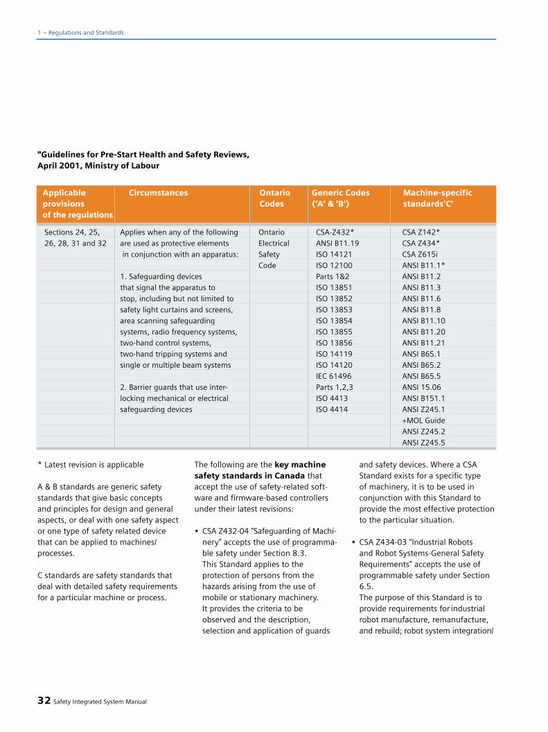
* Latest revision is applicable
A & B standards are generic safetystandards that give basic concepts and principles for design and generalaspects, or deal with one safety aspector one type of safety related devicethat can be applied to machines/processes.
C standards are safety standards thatdeal with detailed safety requirementsfor a particular machine or process.
The following are the key machinesafety standards in Canada thataccept the use of safety-related soft-ware and firmware-based controllersunder their latest revisions:
• CSA Z432-04 “Safeguarding of Machi-nery” accepts the use of programma-ble safety under Section 8.3. This Standard applies to theprotection of persons from the hazards arising from the use of mobile or stationary machinery. It provides the criteria to beobserved and the description, selection and application of guards
and safety devices. Where a CSA Standard exists for a specific type of machinery, it is to be used in conjunction with this Standard to provide the most effective protectionto the particular situation.
• CSA Z434-03 “Industrial Robots and Robot Systems-General Safety Requirements” accepts the use of programmable safety under Section 6.5. The purpose of this Standard is to provide requirements for industrial robot manufacture, remanufacture, and rebuild; robot system integration/
32 Safety Integrated System Manual
1 – Regulations and Standards
Sections 24, 25, Applies when any of the following Ontario CSA-Z432* CSA Z142*26, 28, 31 and 32 are used as protective elements Electrical ANSI B11.19 CSA Z434*
in conjunction with an apparatus: Safety ISO 14121 CSA Z615iCode ISO 12100 ANSI B11.1*
1. Safeguarding devices Parts 1&2 ANSI B11.2that signal the apparatus to ISO 13851 ANSI B11.3stop, including but not limited to ISO 13852 ANSI B11.6safety light curtains and screens, ISO 13853 ANSI B11.8area scanning safeguarding ISO 13854 ANSI B11.10systems, radio frequency systems, ISO 13855 ANSI B11.20two-hand control systems, ISO 13856 ANSI B11.21two-hand tripping systems and ISO 14119 ANSI B65.1single or multiple beam systems ISO 14120 ANSI B65.2
IEC 61496 ANSI B65.52. Barrier guards that use inter- Parts 1,2,3 ANSI 15.06locking mechanical or electrical ISO 4413 ANSI B151.1safeguarding devices ISO 4414 ANSI Z245.1
+MOL GuideANSI Z245.2ANSI Z245.5
Applicable Circumstances Ontario Generic Codes Machine-specificprovisions Codes (‘A‘ & ‘B‘) standards‘C‘of the regulations
"Guidelines for Pre-Start Health and Safety Reviews,April 2001, Ministry of Labour
installation and safeguarding methods to enhance the safety of personnel associated with the use of robots and robot systems.
• CSA Z142-02 “Code for Power Press Operation: Health, Safety and Guarding Re-quirements” accepts the use of a programmable safety underSection 8.1.3.This Standard covers the occupationalhealth and safety requirements for all classes of power presses that are fitted with a ram (plunger or slide) and dies for the purpose of blanking,cutting, trimming, drawing, punching,forming (bending), stamping, assembling, or processing metal and other materials.
• NFPA 79 2002 “Electrical Standardfor Industrial Machines” acceptsthe use of programmable safety under Section 9.4.3. and Section11.3.4. This standard provides detailedinformation about the the applica-tion of electrical/electronic equip-ment, apparatus, or systems suppliedas part of industrial machines that will promote safety to life and pro-perty. The provisions of this Standardapply to the electrical/electronicequipment, apparatus, or systemsof industrial machines, operatingfrom a nominal voltage of 600 voltsor less, and commencing at the point of connection of the supply to the electrical equipment of the machine.
The CSA safety standards require safety-related software and firmware-basedcontrollers to be certified by NationallyRecognized Testing Laboratory (NRTL)or Standards Council of Canada (SCC)-accredited testing laboratory to anapproved standard applicable for safetydevices.
Safety Negligence is a CriminalOffense
• Bill C-45 is a new Act under the Criminal Code, enforceable effective March 31, 2004.
• Canadian Labour Code imposes a legal duty, under the Criminal Code, on employers and those who direct work to take reasonable measures to protect worker and public safety.
• An organization can now be chargedwith criminal negligence concerning health & safety and therefore be investigated and; charged under both the Occupational Health and Safety Act and the Criminal Code.
• Bill C-45 increases the maximum finefor a summary conviction offense from $25,000 to $100,000.And there is no limit on the fine for more serious offenses.
• The maximum penalty for anindividual convicted of criminal negligence is life imprisonment.
Government of Canada, Occupationaland Health Safety in Canada(www.hrsdc.gc.ca)
Government acts to increaseenforcement of workplace healthand safety
The addition of 200 new Health andSafety Inspectors in Ontario wasannounced by the government on the8th of July 2004. This measure targetsworkplaces with poor health and safetyrecords. The government's goal is toreduce workplace injuries by 20% infour years. Based on the average costof a workplace injury, eliminating60,000 injuries annually will also trans-late into savings for businesses of upto $960 million per year. Recruitmentof 100 new inspectors began immedi-ately, marking a major expansion ofthe current force of 230 inspectors.Inspectors will initially target 6000workplaces with the highest injuryrates.
04-78, July 8, 2004, Ministry of Labour(www.gov.on.ca/lab/)
Safety Integrated System Manual 33
1

For applications in Japan
The situation in Japan was previouslydifferent than in Europe and the US.Contrary to Europe and the US, wherethe employer is responsible for safetyat the workplace, in Japan, the employ-ee must take every precaution thatnothing happens to him/her. This is thereason that he may only use appropri-ately trained personnel on a machine.
Comparable, legal requirements regar-ding functional safety - as in Europe -therefore do not exist. Further, productliability does not play such a role as inthe US. However, in the meantime, ithas been recognized that today, thisconcept is no longer adequate. In Japan,a transition is being made over to thebasic principle that applies in bothEurope and the US.
There is no legal requirement to applystandards. However, an administrativerecommendation to apply JIS (JapaneseIndustrial Standards) exists:Japan bases its standards on the Euro-pean concept and has included basicstandards as national standards (referto the Table)
For machinery OEMs and usersoperating worldwide
Japanese machinery construction OEMsthat export their machines must becompliant with European and US legis-lation so that
their products fulfill the requirementsof the target markets. Companies withglobally distributed production facilitiesalso align themselves to the Europeanand American requirements in order tohave, as far as possible, standard safe-ty concepts in all of their plants.
34 Safety Integrated System Manual
1 – Regulations and Standards
1.4 Safety requirementsfor machines in Japan
ISO12100-1 JIS B 9700-1 earlier designation TR B 0008ISO12100-2 JIS B 9700-2 earlier designation TR B 0009ISO14121 (EN1050) JIS B 9702ISO13849-1 (Ed. 1) JIS B 9705-1ISO13849-2 (Ed. 2) JIS B 9705-1IEC60204-1 JIS B 9960-1 without Annex F or Route Map of the
European forewordIEC1508-1 to 7 JIS C 0508IEC 62061 A JIS number has still not been allocated
ISO/IEC number JIS number Note
Fig. 1/15Change in the concept of the responsibility for the safety of machinery in Japan (from: Toshihiro Fujita et.al.: “NECA Activities for Meeting Globalized Standards and Certification”, Robot, Japan Robot Association, March 2004)

Europe
1. CEN Members = sources for thedomestic editions of EN + prEN
AENORAsociación Española de Normalizacióny Certificación (AENOR)Génova, 6E-28004 Madrid
Phone: + 34 91 432 60 00Telefax: + 34 91 310 31 72E-mail: [email protected]
AFNOR
Association Française de Normalisation 11, Avenue Francis de PressenséF-93571 Saint-Denis La Plaine Cedex
Phone: + 33 1 41 62 80 00Telefax: + 33 14 917 90 00
BSI
British Standards Institution 389 Chiswick High RoadGB-London W4 4AL
Phone: + 44 208 996 90 00Telefax: + 44 208 996 74 00
E-mail: first [email protected]: [email protected]
COSMIT
Czech Standards Institute Biskupsky dvùr 5CZ-110 02 Praha 1
Phone: +420 2 218 02 111Telefax: +420 2 218 02 301E-mail : [email protected]
DIN
Deutsches Institut für Normung e.V.Burggrafenstr. 6D-10787 Berlin
Phone: + 49 30 26 01 0Telefax: + 49 30 26 01 12 31E-mail: [email protected]
DS
Dansk Standard Kollegievej 6DK-2920 Charlottenlund
Phone: + 45 39 96 61 01Telefax: + 45 39 96 61 02 E-mail: [email protected]
ELOT
Hellenic Organization for Standardization 313, Acharnon StreetGR-11145 Athens
Phone: + 30 1 212 01 00TX: (0601) 219670 elot grTelefax: + 30 1 228 62 19 E-mail: [email protected]
IBN/BIN
Institut Belge de Normalisation/Belgisch Instituut voor Normalisatie Avenue de la Brabançonne 29/Brabançonnelaan 29B-1000 Bruxelles/Brussel
Phone: + 32 2 738 01 11Telefax: + 32 2 733 42 64E-mail: [email protected]
IPQ
Instituto Português da Qualidade Rua António Gião, 2P-2829-513 Caparica
Phone: + 351 21 294 81 00Telefax: + 351 21 294 81 01E-mail: [email protected]
NEN
Nederlands Normalisatie-InstituutKalfjeslaanPostbus 5059NL-2600 GB Delft
Phone: + 3115690390Telefax: + 3115690190E-mail: [email protected]
NSAI
National Standards Authority of Ireland GlasnevinIRL-Dublin 9
Phone: + 353 1 807 38 00Telefax: + 353 1 807 38 38E-mail: [email protected]
Safety Integrated System Manual 35
1.5 Important Addresses
1

NSF
Norges Standardiseringsforbund PO Box 353 SkøyenN-0213 Oslo
Phone: + 47 22 04 92 00Telefax: + 47 22 04 92 11E-mail: [email protected]
ON
Österreichisches NormungsinstitutPostfach 130Heinestraße 38A-1020 Wien
Phone: + 43 1 213 00Telefax: + 43 1 213 00 818E-mail : [email protected]
SEE
Service de L'Energie de l'EtatOrganisme Luxembourgeois de NormalisationB.P. 10L-2010 Luxembourg
Phone: + 352 46 97 46 1Telefax:+ 352 22 25 24E-mail: [email protected]
SFS
Suomen Standardisoimisliitto r.y. PO Box 116FIN-00240 HelsinkiFinland
Phone: + 358 9 149 93 31Telefax: + 358 9 146 49 25E-mail: [email protected]
SIS
Standardiseringen i Sverige Box 6455S-113 81 Stockholm
Phone: + 46 8 610 30 00Telefax: + 46 8 30 77 57E-mail: [email protected]
SNV
Schweizerische Normen-Vereinigung Bürglistraße 29CH-8400 Winterthur
Phone: + 41 52 224 54 54TX: (045) 755931 snv chTelefax: + 41 52 224 54 74E-mail: [email protected]
STRI
Icelandic Council for StandardizationLaugavegur 178IS-105 Reykjavik
Phone: + 354 520 71 50Telefax: + 354 520 71 71E-mail: [email protected]
UNI
Ente Nazionale Italiano di UnificazioneVia Battistotti Sassi, 11bI-20133 Milano MI
Phone: + 39 02 70 02 41Telefax: + 39 02 70 10 61 06E-mail: [email protected]
CEN
European Comittee forStandardizationRue de Stassrt 36B-1050 Bruxelles
Phone: + 3225500811Telefax: + 3225500819E-mail: [email protected]
CENELEC
European Comittee for Electrotechnical StandardizationRue de Stassrt 35B-1050 Bruxelles
Phone: + 3225196871Telefax: + 3225196919E-mail: [email protected]
2. DIN – Deutsches Institut für Normung e.V., importantStandards committees withreference to machines
NAM
Normenausschuss Maschinenbau(NAM )im DINLyoner Str. 8Postfach 71086460498 Frankfurt/M.
Phone: 069/6603-1341Telefax: 069/6603-1557
36 Safety Integrated System Manual
1 – Regulations and Standards

NWM
Normenausschuss WerkzeugmaschinenCorneliusstraße 460325 Frankfurt
Phone: 069/75608123Telefax: 069/75608111
AGSA, FNErg, FNFW, FNL, NAL,NALS, NAS, Nasg, NI, NKT, NMP,Textilnorm
DIN Deutsches Institut für Normunge.V. 10772 Berlin
Phone: 030/2601-0Telefax: 030/2601-1260
FNCA, FNKä, FWS, Naa, NAD, NL,NÖG, NRK, NÜA
DIN Deutsches Institut für Normunge.V.Zweigstelle KölnKamekestraße 850672 Köln
Phone: 0221/5713-0Telefax: 0221/5713-414
NA EBM
Normenausschuss Eisen-, Blech- undMetallwarenKaiserwerther Str. 13740474 Düsseldorf
Phone: 0211/4564274/276Telefax: 0211/4564277
NA FuO
Normenausschuss Feinmechanik undOptikTurnplatz 275172 Pforzheim
Phone: 07231/918822Telefax: 07231/918833
FAKAU
Normenausschuss KautschuktechnikZeppelinstr. 69Postfach 90036060487 Frankfurt/M.
Phone: 069/7936-0/117Telefax: 069/7936165
DKE
Deutsche Kommission ElektrotechnikElektronikInformationstechnik im DIN und VDEStresemannallee 1560596 Frankfurt/M.
Phone: 069/6308-0Telefax: 069/9632925E-mail: [email protected]
3. Sources for technical regulations in Germany
For EC Directives as well as legislation and regulations
Bundesanzeiger-Verlags GmbHAmsterdamer Straße 19250667 Köln
Phone: (0221) 97668-0Telefax: (0221)
For DIN Standards and VDM Sheets
Beuth Verlag GmbHBurggrafenstraße 610787 Berlin
Phone: (030) 2601-0Telefax: (030) 2601-1260
For VDE Regulations as well as DKEand IEC Standards
VDE-Verlag GmbHBismarckstraße 3310625 Berlin
Phone: (030) 348001-16Telefax: (030) 3417093
For accident prevention regula-tions and ZH-1 documents fromthe Trade Associations
Carl Heymanns Verlag KGLuxemburger Straße 44950939 Köln
Phone: (0221) 94373-0Telefax: (0221) 94373-901
Safety Integrated System Manual 37
1
Information about Standards,Regulations, Directives
Deutsches Informationszentrum fürTechnische Regeln (DITR) im DIN(Deutsches Institut für Normung)Burggrafenstraße 610787 Berlin
Phone: (030) 2601-0Telefax: (030) 2628125
America
Additional information about machinesafety
ANSI(American National StandardsInstitute)http://www.ansi.org
OSHA(Occupational Safety and HealthAdministration)http://www.osha.gov
NFPA(National Fire Protection Association)http://www.nfpa.org
TUVRheinland of N.A. Inc.http://www.us.tuv.com
UL(Underwriter Laboratories)http://www.ul.com
CSA(Canadian Standards Association)http://www.csa.ca
CCOHS(Canadian Center for Occupational -Health and Safety)http://www.ccohs.ca
NIOSH(National Institute of OccupationalHealth and Safety)http://www.cdc.gov/niosh/homepage.html
NSC(National Safety Council)http://www.nsc.org
ASSE(American Society of Safety Engineers)http://www.asse.org
RIA(Robotic Industries Association)http://www.robotics.org
Global Engineering Documentshttp://www.global.his.com
38 Safety Integrated System Manual
1 – Regulations and Standards

Safety Integrated System Manual 39
1


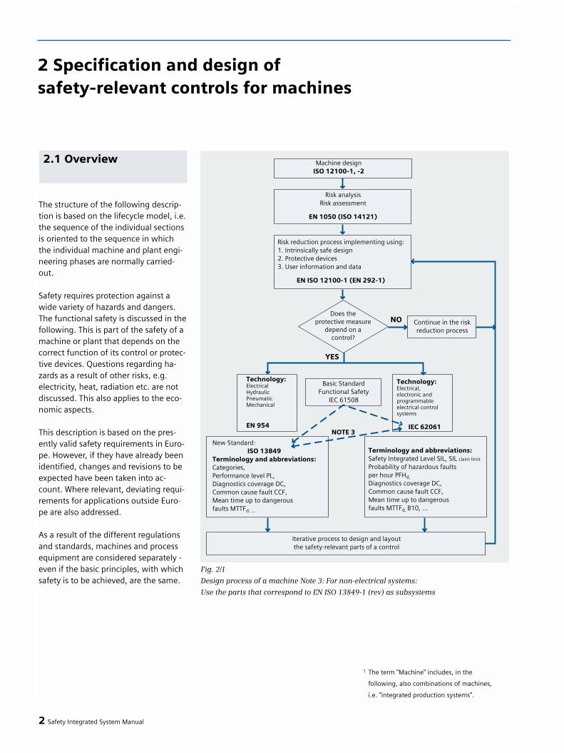
The structure of the following descrip-tion is based on the lifecycle model, i.e.the sequence of the individual sectionsis oriented to the sequence in whichthe individual machine and plant engi-neering phases are normally carried-out.
Safety requires protection against awide variety of hazards and dangers.The functional safety is discussed in thefollowing. This is part of the safety of amachine or plant that depends on thecorrect function of its control or protec-tive devices. Questions regarding ha-zards as a result of other risks, e.g.electricity, heat, radiation etc. are notdiscussed. This also applies to the eco-nomic aspects.
This description is based on the pres-ently valid safety requirements in Euro-pe. However, if they have already beenidentified, changes and revisions to beexpected have been taken into ac-count. Where relevant, deviating requi-rements for applications outside Euro-pe are also addressed.
As a result of the different regulationsand standards, machines and processequipment are considered separately -even if the basic principles, with whichsafety is to be achieved, are the same.
2 Safety Integrated System Manual
2 Specification and design of safety-relevant controls for machines
2.1 Overview
Fig. 2/1
Design process of a machine Note 3: For non-electrical systems:
Use the parts that correspond to EN ISO 13849-1 (rev) as subsystems
1 The term “Machine” includes, in the
following, also combinations of machines,
i.e. “integrated production systems”.

The lifecycle of a machine is roughlysubdivided into the sections shown in2/1. The individual phases encompassclearly defined tasks so that specificsteps can be executed by different per-sons or organizations.
One strategy to reduce the risk of a ma-chine is described in ISO 12100-1Chapter 5. This clearly states the priori-ty that must be allocated to the variousaspects of the machine design.
When carrying-out this process, it is necessary to take into account thefollowing sequence:
• Safety of the machine over its complete lifecycle
• The ability of a machine toexecute its functions
• User-friendliness of the machine• Manufacturing, operating and
disassembly costs of the machine
The process of reducing risks of a parti-cular machine is realized in an iterativeprocess. The individual steps are des-cribed in EN 1050 (also refer toChapter 1 of this Manual). The processof reducing risks encompasses the riskassessment and, where necessary,determining the measures to reducerisks.
Basic technical principles are describedin ISO 12100-2. These help mechanicalengineers when designing machineryto construct a safe machine. The firstand foremost objective is to achieveinherent safety of the machine. Only
then should appropriate measures(e.g. guards) be provided to addressremaining hazards and dangers (referto ISO 12100-2 Chapter 4). The suita-ble implementation of safety-relatedcontrol functions is an essential ele-ment in achieving inherent safety(refer to ISO 12100-2 Section 4.11).Reference is made to IEC 61508 for
controls that contain programmableelectronic components.
There are C Standards for manymachine types. These already definethe necessary measures to reduce thelevel of risk. They define the protectivemeasures required with the associatedSafety Performance - i.e. the required
Safety Integrated System Manual 3
22.2 Design andimplementation processof the machine, riskassessment, processto reduce risks
Fig. 2/2
Process to reduce risk

categories for the safety-related partsof controls.
In order to take into account technicaldevelopment, or if there is no applica-ble C Standard, in many cases, whenmechanically designing a machine, thisprocess must be repeated. The riskreducing measures to be implementedshould then be defined taking intoaccount current state-of-the-art tech-nology.
By specifying the safety requirements,the machine design engineer definesthe requirements placed on the controland the protective equipment anddevices. This specification includes aprecise description of the individualsafety functions and their requiredSafety Performance.
Defining measures necessa-ry to reduce risk
For many machine times, there arespecific C standards in which thenecessary protective measures are alre-ady defined. The machinery manufac-turer can apply these Standards if theyapply for the machine being conside-red and he can then assume (refer toChapter 1 “Presumption of conforman-ce”) that the safety goals of the EUMachinery Directive are fulfilled. In this case, the necessary Categoriesaccording to EN 954 should be speci-fied for the safety-related control func-tions.
If the intended technical implementa-tion of the machine considered corres-ponds to the information in the CStandard, then the risk analysis steps,described in the following, do not haveto be repeated. The safety functionsand their Safety Performance, i.e. therequired Category,
are specified by the C Standard.If complex electronic equipment - e.g.safety PLC controllers - are used toimplement safety functions, then thespecified category cannot be directlyapplied. The requirements associated with theCategories of EN 954 are, alone, notsufficient. Programmable controls forsafety tasks must be in compliancewith IEC 61508. In order to fulfill pro-tective goals associated with a specificcategory, the programmable controlmust achieve the assigned SIL accor-ding to Fig. 2/3.
If the machine design deviates fromthe specifications listed in the CStandard, for example, in order to utili-ze new functionality of electronic safe-ty controls or safety-related drive func-tions, a risk analysis must be carried-out, and the appropriate SafetyPerformance (footnote 2) must bedetermined for the new technology.
4 Safety Integrated System Manual
2 – Specification and design of safety-related controls and machines
Fig. 2/3
SIL necessary to fulfill specific categories

Defining the limits of a machine
The machine design starts with thedefinition of its limits. These include:
• Limits of use: This is the definition of correct use including the various operating types, phases of use and different intervention-possibilities for the user, as well as sensible, predictableincorrect use.
• Spatial limits: (e.g., space for motion, space requirement for installation and maintenance, “operator/machine” and “machine/power feed” interfa-ces)
• Ambient/environmental limits: Limit values for ambient conditions, e.g. temperature, humidity
• Time limits: Defining the predictable “lifetime limit” of the machine, taking into account its - correct use and/or several of its parts (e.g.tool, parts subject to wear, electronic compo-nents).
Identification of possible hazards
After the limits of the machine beingconsidered have been defined, all ofthe possible hazards that can arisefrom this machine are identified.(Chapter 4 of ISO 12100-1 includes a list of possible hazards to be con-sidered.)
When identifying possible hazards, itshould also be investigated as to whet-her functional faults or failures relatingto the control, control devices or exis-ting protective equipment, can resultin hazards. Possible incorrect behavior(e.g. the control generates an on sig-nal although an off signal is outputand should be kept) should be analy-zed regarding its effect on the machineand its protective devices and equip-ment. In this case, it does not have tobe investigated as to which “internalcauses” in the equipment being consi-dered, can result in an incorrect func-tion.
For every possible functional fault itshould be investigated as to whichhazards could possibly be generated.For instance, it should be checked,
• Whether any fault or a combination of faults in the control can result in a dangerous (incorrect) function of the machine (e.g. accidental star-ting)
• Whether, when using variable-speed drives, if the actual speed deviates from the setpoint speed, a hazard is generated.
• Whether the failure of an operator-command (e.g. stop command can result in a hazard
To start, for the risk analysis, the“worst case” investigation is used asbasis. This means that it must be assu-med that functional faults can occur. Ifthis analysis indicates that a functionalfault can cause a hazard, then thisfunction is safety-related and a riskassessment must be made. Dependingon the result of this risk assessment,measures to reduce the risk are required.
Safety Integrated System Manual 5
2
2 The term “Safety Performance” is used here
as a higher-level term for safety-
relevant performance of the
control. It encompasses the “Category”,
“Safety Integrity” and “Performance Level”
terms used in the various Standards.

Risk assessment and risk evalua-tion
Also refer to EN 1050 Chapters 7 and 8.
For all of the previously identifiedhazards, the associated risks must beevaluated. If the risk of a specifichazard exceeds a tolerable level, thenmeasures must be applied to reducethis risk.
Note: The result of the evaluationshould be documented for each indivi-dual hazard.
A risk is created by the interaction ofvarious causes (refer to Fig. 2/4).
• Severity of the possible damage• Frequency with which somebody
stays in the hazardous area• Probability that the dangerous event
actually occurs• Possibility of avoiding or reducing
the damage
Its magnitude can be estimated by eva-luating these elements.
Risk reduction
If the estimated risk appears too high,then it must be reduced. To start, an at-tempt must be made to achieve this bymodifying the mechanical design ofthe machine to make it safe (refer tothe Machinery Directive, Appendix I (1)1.1.2 and ISO 12100-1 Chapter 5.4). Ifthis is not possible, then the risk mustbe minimized by using suitable protec-tive measures.
• The severity of possible damage can,for example, be reduced by reducing the speed of motion or forces of machine-parts while personnel are present.
• Using guards and similar devices, it ispossible to reduce the frequency with which personnel are in the hazardous zone.
• There is always a certain probability that a machine does not behave as itshould (i.e. for which it was origi-nally designed) or protective devices fail. This can be caused by
faults in any parts of the machine. This risk factor can be reduced bysuitably designing and implemen-ting the safety-related parts and components. The control of the machine also belongs to the safety-relevant parts if, due to its failure, a hazard can occur. The risk that is caused bya control fault can be reduced by implementing the control acc. toIEC 62061.
• The possibility that damage can be avoided, can be increased, among other things, if the-hazardous states are identified early on, e.g. using signal lamps.
The probability of the occurrence of anundesirable event is a common para-meter of all of these elements. The riskcan be reduced by reducing this proba-bility (refer to Fig. 2/5).
6 Safety Integrated System Manual
2 – Specification and design of safety-related controls and machines
Fig. 2/4
Elements of risk evaluation

Measures regarding risk reduction
The risk assessment concept is orientedto the possible hazards. It specifies thatfor each identified hazard, suitable me-asures must be applied to remove it.Or, if this is not possible, then the pro-bability that it occurs, must be adequa-tely reduced.
Safety-related control functions
If the risk assessment indicated that ahazard is generated by a possible func-tional fault of the control, this risk canbe reduced by appropriately reducingthe probability of dangerous controlfaults.
Situations such as this are, for example,present if a machine is stopped so thatservice or setting-up work can be car-ried-out or the speed of the machine isreduce so that personnel can safetywork at the machine. In this case, a ha-zard can occur if the machine was tounexpectedly start or suddenly accele-rate - e.g. due to a control fault.
If the range of motion is limited forspecific activities to protect the opera-tor, then if this limit fails, it can resultin a hazard.
The probability of failure of this func-tion must therefore be sufficiently lowin order to limit the risk to a tolerablelevel.
Example (1) safety-related control func-tion
Machine with several moving parts(axes). There is a danger of injury dueto the movement of each of theseparts. The operator must enter the ha-zardous zone in order to carry-out re-pair and service work, but the machineshould not be completely shut down asotherwise the product is (could be) da-maged.
During repair, in order to protect theoperator and the product, the speed ofmotion is limited to a non-dangerouslevel or specific parts of the machinesare kept in a defined position. Whenvelocity limits and positions are to bemaintained, then this represents a safe-ty-related function. If the associatedcontrol function would fail, this wouldresult in a potential hazard for the ope-rator (e.g. as a result of unexpected ac-celeration, crushing etc. when leavingthe position).
In this particular case, the safety func-tion is: “Limiting the speed of specificmachine parts and maintaining the se-lected position of certain machineparts. If a limit value is exceeded, e.g.,due to a fault, then the drive involvedshould be shut down and a mechanicalbrake applied.”
A risk evaluation must be carried-outfor this situation in order to determinethe necessary Safety Performance ofthe safety function.
Safety Integrated System Manual 7
2
Fig. 2/5
Reducing risks
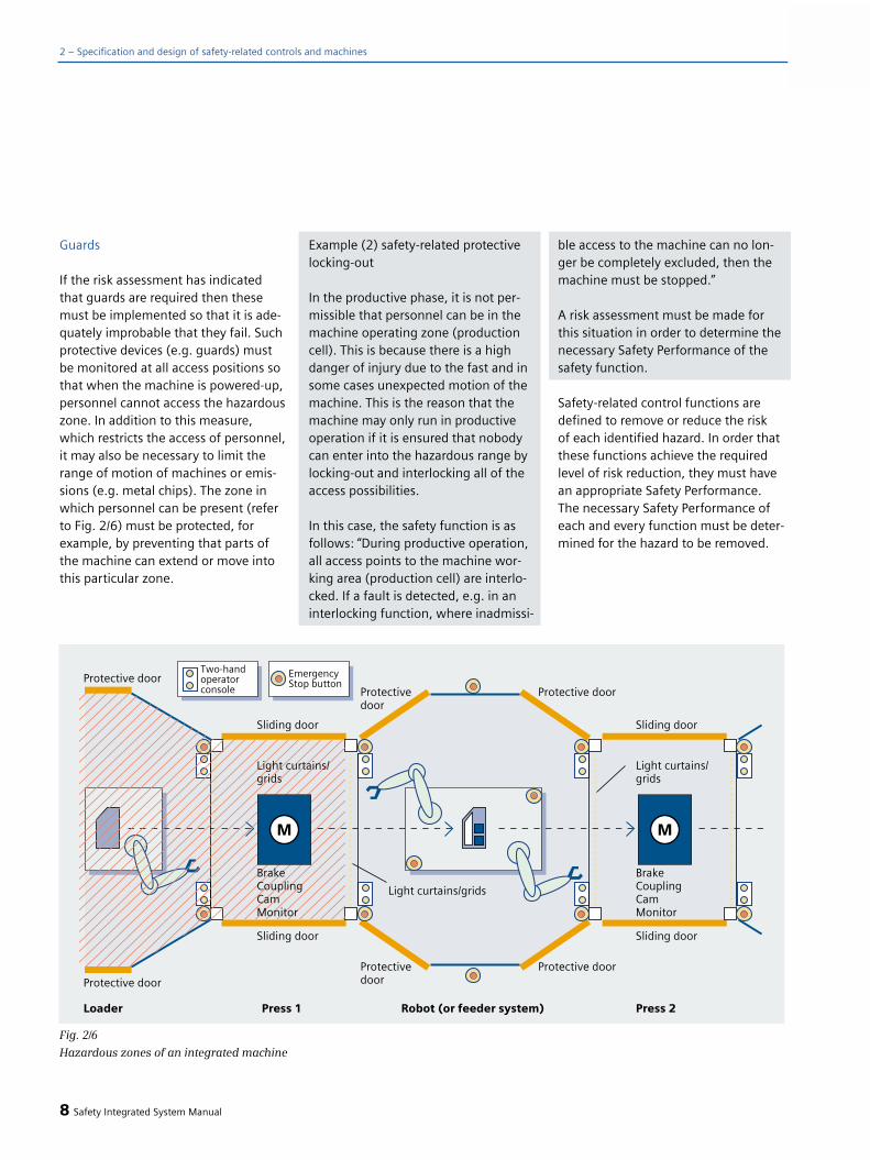
2 – Specification and design of safety-related controls and machines
Guards
If the risk assessment has indicatedthat guards are required then thesemust be implemented so that it is ade-quately improbable that they fail. Suchprotective devices (e.g. guards) mustbe monitored at all access positions sothat when the machine is powered-up,personnel cannot access the hazardouszone. In addition to this measure,which restricts the access of personnel,it may also be necessary to limit therange of motion of machines or emis-sions (e.g. metal chips). The zone inwhich personnel can be present (referto Fig. 2/6) must be protected, forexample, by preventing that parts ofthe machine can extend or move intothis particular zone.
Example (2) safety-related protectivelocking-out
In the productive phase, it is not per-missible that personnel can be in themachine operating zone (productioncell). This is because there is a highdanger of injury due to the fast and insome cases unexpected motion of themachine. This is the reason that themachine may only run in productiveoperation if it is ensured that nobodycan enter into the hazardous range bylocking-out and interlocking all of theaccess possibilities.
In this case, the safety function is asfollows: “During productive operation,all access points to the machine wor-king area (production cell) are interlo-cked. If a fault is detected, e.g. in aninterlocking function, where inadmissi-
ble access to the machine can no lon-ger be completely excluded, then themachine must be stopped.”
A risk assessment must be made forthis situation in order to determine thenecessary Safety Performance of thesafety function.
Safety-related control functions aredefined to remove or reduce the risk of each identified hazard. In order thatthese functions achieve the requiredlevel of risk reduction, they must havean appropriate Safety Performance. The necessary Safety Performance ofeach and every function must be deter-mined for the hazard to be removed.
8 Safety Integrated System Manual
Fig. 2/6
Hazardous zones of an integrated machine
Risk elements according toEN 1050 (ISO 14121)
The assessment according to EN 1050allows the risk to be assessed usingfour risk elements:
• Severity of the possible damage
• Frequency with which personnel stay in the hazardous zone
• Probability that a dangerous event occurs
• Possibility of avoiding orreducing damage
In turn, these risk elements form theinput parameters to implement a safe-ty-related control function: They permita risk to be allocated to the require-ments of the safety-related control.
This is the reason that EN 954-1 - i.e.also IEC 62061 - offer a technique toevaluate the risk elements and to clas-sify the Safety Performance.
Determining the necessarySafety Performance (SafetyIntegrity)
If, when assessing and investigatingthe risk, it was defined that functionalfaults of the control or the failure ofprotective devices could result in a highrisk, then their probability must be re-duced until the remaining risk can betolerated. This means that the controlmust achieve adequate “Safety Perfor-mance ”.
In order to answer the question as towhat can be adequately assumed to besafe, up until now, the technique (riskdiagram) shown in Appendix B of EN954-1 / ISO 13849-1 was used. Thisthen allowed “specific categories” to bedetermined for the safety-related con-trol functions.
Now, in the form of IEC 62061, in addi-tion to EN 954, there is a new Standardfor safety-related machine controls. Atechnique is described in this Standardthat uses a quantified - and thereforehierarchic graduation - of the SafetyPerformance orientated to the probabi-lity. The result of the risk analysis isthen the Safety Integrity Level (SIL) forthe safety functions involved.
A similar, quantified and therefore hier-archic graduation of the Safety Perfor-mance will be introduced with the newEdition of ISO 13849-1. The level, desi-gnated there as Performance Level (PL)correlates with the SILs of IEC 62061through the assigned probability of fai-lure.
The techniques described in both ofthese standards are based on the sameprinciples. This is the reason that theuser can select which standard he wis-hes to apply. The responsible technicalcommittees of IEC and ISO recommendthe selection specified in the followingtable (Fig. 2/11).
Note: If a C standard exists for the ma-chine type being considered, then theprotective measures described therehave priority and should be predomi-nantly implemented with the specifiedCategories. However, the specificationsshould be checked to see whether theycorrespond to the latest technical deve-lopments.
Safety performance to implementthe control according to EN 954
A technique to determine the necessa-ry category for a specific risk is descri-bed in EN 954-1. However, the catego-ries are not hierarchically structured.This is the reason that the risk diagram,shown in Fig. 2/7, is only a recommen-dation. Further, this technique meansthat different categories can be selec-ted for a specific risk. The result is notclear and can also be influenced by thetechnology of the solution being used.
Safety Integrated System Manual 9
22.3 Does the protectivemeasure depend on thecontrol?
3 The measure for “Safety Performance” is defined differently in the various standards:
Categories in EN 954, Safety Integrity Level (SIL) in IEC/EN 61508 and IEC 62061 and Performance
Level (PL) in draft ISO 13849-1(rev).
4 The term “Safety Performance” is used here as higher-level term for the safety-related performance
of the control system. It encompasses the “Category”, “Safety Integrity” and “Performance Level”
terms used in the various Standards".
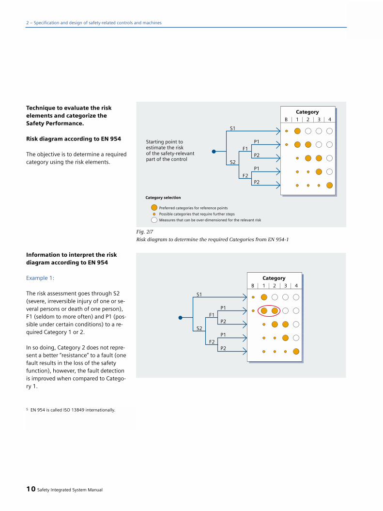
Technique to evaluate the risk elements and categorize the Safety Performance.
Risk diagram according to EN 954
The objective is to determine a requiredcategory using the risk elements.
Information to interpret the riskdiagram according to EN 954
Example 1:
The risk assessment goes through S2(severe, irreversible injury of one or se-veral persons or death of one person),F1 (seldom to more often) and P1 (pos-sible under certain conditions) to a re-quired Category 1 or 2.
In so doing, Category 2 does not repre-sent a better “resistance” to a fault (onefault results in the loss of the safetyfunction), however, the fault detectionis improved when compared to Catego-ry 1.
10 Safety Integrated System Manual
2 – Specification and design of safety-related controls and machines
Fig. 2/7
Risk diagram to determine the required Categories from EN 954-1
5 EN 954 is called ISO 13849 internationally.

Example 2:
The immunity with respect to faultscan be increased by additional measu-res, but the category remains thesame.
In this example, the category reachedis just as before, Category 2.
Example 3:
The required Category 3 cannot be rea-ched using supplementary measureswith another category (in this casewith Category 2).In this example, although the same risk is covered (the same “Safety Perfor-mance” reached), however, the riskassessment demands, just as before, a Category 3 to reduce risk.
A hierarchically graduated, quantifiedlevel for the Safety Performance - desi-gnated as Performance Level (PL) - isintroduced with the scheduled newEdition of EN 954-1 as ISO 13849-1(rev) (refer to Fig. 2/8). This thereforeavoids any ambiguity when selectingthe appropriate category.
Safety Integrated System Manual 11
2

Risk diagram according to prEN ISO13849-1
The objective is to determine a requiredPerformance Level PLr - i.e. the probabi-lity of dangerous failures in the systemusing the risk elements.
The Performance Level (PL) is a quanti-tative measure of the Safety Perfor-mance just like the Safety IntegrityLevel (SIL) in IEC 61508 and IEC 62061.Fig. 2/9 shows the inter-relationshipbetween these two parameters.
Initially, this apparent variance appearsconfusing. However, there are defined relations-hips between the various levels of therequired Safety Performance.
The responsible bodies and associa-tions have still not officially defined theallocation of the required categories tothe required Performance Levels or Sa-fety Integrity Levels. However, the fol-lowing allocation can be made,
12 Safety Integrated System Manual
2 – Specification and design of safety-related controls and machines
Fig. 2/8
Risk diagram (Draft) according to ISO 13849-1 (rev) to determine the required Performance Level
6 The risk diagram shown is a draft that still has to be discussed in the responsible associations and committees.

based on the same risk parameters,from the risk diagrams in Figs. 2/7 and2/8:
Category 1 q PLr b q SIL 1Category 2 q PLr c q SIL 1Category 3 q PLr d q SIL 2Category 4 q PLr e q SIL 3
This allocation of a required Categoryto the required PLr or SIL should beconsidered to be a simplification. On a case-for-case basis, as a result of themultiple interpretation for the catego-ries, the special issues associated withthe particular application should betaken into consideration.
Safety Performance for implemen-ting a control in compliance withIEC 62061
The technique described in Appendix Ain IEC 62061 is also based on the riskparameters defined in EN 1050; howe-ver, contrary to ISO 13849-1 it uses atabular technique that can be directlyused to document the risk evaluationcarried-out and allocation to a particu-lar SIL.
The associated weighting should be se-lected for the individual risk parametersusing the values specified in the headerof the table. The sum of the weightingof all parameters provides the probabi-lity class of the damage.
Cl = Fr + Pr + Av
Refer to the explanation on Fig. 2/10.
Using this probability class and the pos-sible severity of damage of the hazardbeing considered, the necessary SIL forthe associated safety function can beread from the table.
Safety Integrated System Manual 13
2a ≥ 10-5 to < 10-4 no special safety requirementsb ≥ 3x 10⁻⁶ to < 10-5 1c ≥ 10-6 to < 3x10⁻⁶ 1d ≥ 10-7 to < 10-6 2e ≥ 10-8 to < 10-7 3Comment 1:The representation of each hazardous situation is subdivided into 5 stages from a to e. In this case, the risk reductionfor a is the lowest, for e, the highest.Comment 2:Performance Levels b and c together cover one order on the magnitude scale of the average probability ofdangerous failures per hour (also on the SIL scale).
Performance Average probability of SIL EN 61508-1 level PL dangerous failures (IEC 61508-1)
within one hour for information
Fig. 2/9Performance Level
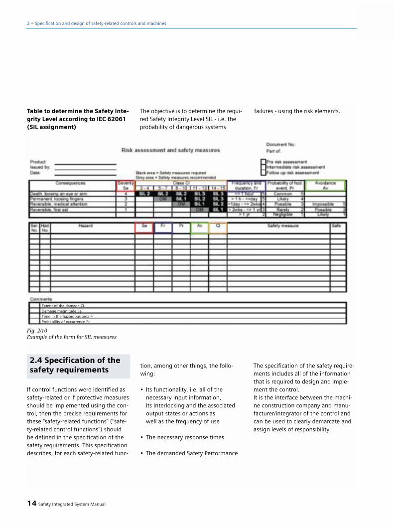
Table to determine the Safety Inte-grity Level according to IEC 62061(SIL assignment)
The objective is to determine the requi-red Safety Integrity Level SIL - i.e. theprobability of dangerous systems
failures - using the risk elements.
14 Safety Integrated System Manual
2 – Specification and design of safety-related controls and machines
Fig. 2/10Example of the form for SIL measures
Extent of the damage CLDamage magnitude SeTime in the hazardous area FrProbability of occurrence Pr
2.4 Specification of thesafety requirements
If control functions were identified assafety-related or if protective measuresshould be implemented using the con-trol, then the precise requirements forthese “safety-related functions” (“safe-ty-related control functions”) shouldbe defined in the specification of thesafety requirements. This specificationdescribes, for each safety-related func-
tion, among other things, the follo-wing:
• Its functionality, i.e. all of thenecessary input information, its interlocking and the associatedoutput states or actions as well as the frequency of use
• The necessary response times
• The demanded Safety Performance
The specification of the safety require-ments includes all of the informationthat is required to design and imple-ment the control. It is the interface between the machi-ne construction company and manu-facturer/integrator of the control andcan be used to clearly demarcate andassign levels of responsibility.

Design and implementationof safety-related controls
Which standard is to be applied -ISO 13849 or IEC 62061?
A safety-related control for machinescan be implemented, both according toIEC 62061 as well as also according toISO 13849. The safety objectives
of the Machinery Directive regardingfunctional safety are fulfilled with therequirements of each of the two stan-dards. The following table provides
help when deciding which of the stan-dards to select - that is provided as re-commendation in the foreword of bothof these standards.
Safety Integrated System Manual 15
2
A Non-electrical, e.g. hydraulic X Not coveredB Electromechanical, e.g. relays and/ Limited to designated All architectures and
or simple electronics architectures (refer to Comment 1) max. up to SIL 3 and max. up to PL = e
C Complex electronics, Limited to designated All architectures ande.g. programmable electronics architectures (refer to Comment 1) max. up to SIL 3
and max. up to PL = d D A combined with B Limited to designated X refer to Comment 3
architectures (refer to Comment 1)and max. up to PL=e
E C combined with B Limited to designated All architectures andarchitectures (refer to Comment 1) max. up to SIL 3and max. up to PL = d
F C combined with A, or C X refer to Comment 2 X refer to Comment 3combined with A and B
“X” indicates that the point is covered by this standard.Comments1 Designated architectures are described in Appendix B of EN ISO 13849-1 and provide a simplified
basis for quantification.2 For complex electronics: Using designated architectures in compliance with EN ISO 13849-1
up to PL = d or every architecture in compliance with IEC 62061.3 For non-electrical systems: Use the parts that correspond to EN ISO 13849-1 (rev) as subsystems.
Technology to implement EN ISO 13849-1(rev.) IEC 62061safety-related control functions
Fig. 2/11
Recommended use of IEC 62061 & ISO 13849-1 (rev.)
Note:
In January 2005, IEC 62061 was pub-lished as IS and is ratified as EN 62061.In 2004, ISO 13849-1 (rev) publishedthe Draft prEN ISO 13849-1 (and DIS ISO 13849-1) for comments. As aresult of the comments that were recei-ved, changes can still be expected be-fore ISO 13849-1 can be published forfinal voting. A final edition can be ex-pected, at the earliest, at the end of2005.
Formally, presently only EN 954-1 isharmonized under the Machinery Di-rective (beginning of 2005). Thismakes it the binding Standard to fulfillthe EU Machinery Directive. However,when applying IEC 62061, the require-ments of EN 954-1 are fulfilled and be-yond this, also the current state-of-the-art technology for programmable elec-tronic systems, including bus commu-nication.
The draft of ISO 13849-1 addresses,just the same as EN 954-1, varioustechnologies. For instance, electrical,hydraulic, pneumatic and mechanical.
The objective is to be able to imple-ment a safety-related control functionbased on the “intended architectures”and an appropriate category: This re-flects today's implementation strate-gies that are practiced.
No statements were made regardingsafety-related software. In fact, quitethe contrary, reference was explicitlymade to other Standards (for example,the subject of software is described indetail in the IEC 62061).
16 Safety Integrated System Manual
2 – Specification and design of safety-related controls and machines

Goal: A safety-related (control) systemmust correctly execute a safety func-tion. Even when a fault develops, itmust behave so that the machine orplant either remains in a safe conditionor is brought into a safe position.
Determining the necessarySafety Performance (SafetyIntegrity)
Also refer to Chapter 2.3 “Does the pro-tective measure depend on a control?”
Philosophy/theory
Principle structure for a safety-re-lated control system
The essential prerequisite that a controlcorrectly functions as it was originallyintended is its correct construction. Inorder to achieve this objective, IEC62061 has defined a systematic topdown design process:
A safety-related electrical control sys-tem (SRECS) includes all components -from information detection througharithmetic and logical operations up toand including the execution of actions.In order to permit a straightforward,systematic procedure to create the de-sign that should fulfill the safety-rela-ted evaluation and the implementationof an SRECS, which fulfills the require-ments of IEC 61508, IEC 62061 uses astructure that is based on the followingarchitectural elements (refer to Fig. 2/12)(this structure can also be used if thesafety-related parts of the control areto be implemented acc. to EN 954).
To start, a differentiation is made bet-ween a “virtual (i.e. functional) per-spective” and the “real (i.e. system) per-spective”. The functional perspectiveonly considers the functional aspects,independent of the implementationusing hardware and software. For in-stance, in the virtual perspective, con-sideration is only given to which infor-mation is to be detected, how this is to be processed and which action can
result from it. However, no statement ismade whether, e.g. redundant sensorsare required in order to detect informa-tion - or how the actuators are to beimplemented. The implementationusing a SRECS is only considered withthe “real perspective”. In this case, itmust be decided, for example, whetherone or two sensors are required to de-tect certain information in order toachieve the required Safety Performan-ce level. The following terminology wasdefined.
Terminology to structure the func-tions (functional perspective):
Safety-related control functionControl function with a defined level ofintegrity that is executed by an SRECSwith the goal of maintaining the safecondition of the machine or preventinghazardous situations at the machine.
Function blockSmallest unit of a safety-related controlfunction (SRCF), whose failure resultsin the failure of the safety-related con-trol function.
Comment: In IEC 62061, an SRCF (F) isconsidered as logically ANDing thefunction blocks (FB), e.g. F = FB1 & FB2& ... & FBn.
The definition of a function block dif-fers from that used in IEC 61131 andother Standards.
Safety Integrated System Manual 17
22.5 Design and imple-mentation of (safety-related) controls accor-ding to IEC 62061

Function block elementPart of a function block.
Terminology used when structuring a real system (system perspective):
Safety-related electrical control systemElectrical control system of a machinewhose failure can result in the immedi-ate increase of the risk.
Comment: An SRECS encompasses allparts of an electrical control systemwhose failure can result in the reduc-tion of the functional safety or in theloss of the functional safety. This caninclude both - power and control circu-its.
SubsystemElement of the architectural design ofthe SRECS at the topmost level. Where-by, if any subsystem fails, this results infailure of the safety-related controlfunction.
Comment: Contrary to the general useof terminology, where “subsystem” canmean any unit that has been created bysplitting-up the total entity, “subsystem”in IEC 62061 is used in a strictly defi-ned hierarchy of the terminology. “Sub-system” means the subdivision at thetopmost level. The parts that are crea-ted from additional subdivision of asubsystem are known as “subsystemelements”.
Subsystem elementPart of a subsystem that includes theindividual components or a group ofcomponents.
Using these structural elements, con-trol functions can be structured accor-ding to a clearly defined technique sothat defined parts of the function(function blocks) can be assigned spe-cific hardware components - the sub-systems. This means that clearly defi-ned requirements are obtained for theindividual subsystems so they can bedesigned and implemented independ-ently of one another.
The architecture to implement thecomplete control system is obtained byarranging the subsystems with respectto one another just the same as thefunction blocks are arranged within thefunction (logically).
18 Safety Integrated System Manual
2 – Specification and design of safety-related controls and machines
Fig. 2/12
Structural elements of the system architecture

Process to design a safety-related control systemSRECS
If the safety requirement specificationsare available, the intended control sys-tem can be designed and implemen-ted. A control system that fulfills thespecific requirements of a particularapplication can generally not be pur-chased pre-configured, but insteadmust be designed and constructed indi-vidually for the particular machinefrom the devices that are available.
In the design process (refer to Fig.2/13), initially, a suitable control sys-tem architecture is designed for eachsafety function. The architectures of allsafety functions of the particular ma-chine can then be integrated to form acontrol system.
Safety Integrated System Manual 19
2
Fig. 2/13
Process to design a safety-related control system

Structuring the safety function
The basic principle of the structureddesign is that each control function issubdivided into (intended) functionblocks so that these can be assigned tospecific subsystems (Fig. 2/14). The de-marcation of the individual functionblocks is selected so that they can becompletely executed by certain subsys-tems. In so doing it is important thatevery function block represents a logi-cal unit that must be correctly executedso that the complete safety function iscorrectly executed.
Generally, a control function comprisesbasic elements (Fig. 2/15).
• Detecting (e.g. machine states/condi-tions, operator commands, states of the protective devices and equip-ment)
• Interlocking (i.e. interlocking thestatus/condition information, opera-tor commands, etc. and if required, deriving an action)
• Executing (... the action initiated from the interlocking - logical opera-tion)
In the sense of the specification of a sa-fety function, every piece of informa-tion and data to be detected is assig-ned a dedicated “function block”. In thesame way, every action to be executedis assigned a dedicated “function block”.The interlocking and logical operationsapplied to the information and datathat has been detected - this is the sa-fety function logic - is also considered
as a dedicated subfunction. This meansthat it is also assigned to a “functionblock”. This “logic” function block initia-tes, dependent on the information anddata detected, the actions to be execu-
ted. This means that several functionblocks can belong to a safety-relatedfunction - both for detecting as well asfor executing.
20 Safety Integrated System Manual
2 – Specification and design of safety-related controls and machines
Fig. 2/14
Subdivision of a safety function into function blocks and assignment to subsystems
Fig. 2/15
Basic elements of a control function

As a result of these inter-relationships,the Safety Performance required for thecomplete safety function can be trans-ferred as follows to the function blocksand the subsystems assigned to them.(EN 954 and IEC 62061 are considered separately in the following due to theirdifferent concepts.)
Note:
In this first step, only the demarcationof the function blocks and the subdivi-sion of the system into subsystems (asdefined above!) is made. If it is neces-sary to consider the subsystems, thenthis is only done in a next step that isdescribed below.
Required Safety Performance ofthe subsystems
The Safety Performance of a safety-re-lated control system always refers tothe complete safety-related function -as defined in the safety requirementsspecification for the system. Using thegeneral structure described above, therequired Safety Performance can bederived for the individual subsystems.
There are differences in the systemolo-gy of the requirements of IEC 61508and IEC 62061 on one hand and EN954 (or ISO 13849) on the other hand.This results in differences when deter-mining the details of the required Safe-ty Performance of a subsystem.
Safety Integrated System Manual 21
2Subdivision of a safety function into function blocks for example (2) simple safety function F described for the measures to reduce risks, that prevents access to the hazardous zone while the machine isrunning:
F = During productive operation, all access entry points to the workingzone of the machine (production cell) are interlocked.
The subdivision results in the function blocks:F1 = Detecting the selected statusF2 = Logic: Dependent on the selected operating mode, initiate inter-
locking of doors A and B, F3 = Interlock door AF4 = Interlock door BThe individual function blocks have defined limits so that to correctly imple-ment and execute safety function F, all of its function blocks must be correctly executed. Therefore the following logical operation applies
F = F1 `and´ F2 `and´ F3 `and´ F4;
Behavior when a fault develops:If a fault, e.g. is detected in an interlocking function, so that unauthorizedaccess to the machine can no longer be excluded, then the machine mustbe stopped.

Safety Performance of a subsystemacc. to IEC 61508 and IEC 62061
“Safety Integrity” acc. to IEC 61508*and therefore also IEC 62061) specifythat three basic requirements must becomplied with: (1) systematic integrity), (2) structural restrictions,
i.e. the fault tolerance and(3) limited probability dangerous,
random (hardware) failures (PFHD).that are graduated according to the SIL.
The systematic integrity (1) of the sys-tem, specified and required for thecomplete function as well as the struc-tural restrictions (2) apply to the indivi-dual subsystems, just the same as forthe system. This means that if each in-dividual subsystem fulfills the requiredsystematic integrity and the structuralrestrictions of a specific SIL, then thesystem also fulfills it. However, if a sub-system only fulfills the lower require-ments of a lower SIL, then this limitsthe SIL that the system can achieve.This is the reason that a “SIL claim limit”(SIL CL) is defined for a subsystem.
• Systematic integrity: SIL SYS <= SIL CLlowest
• Structural restrictions: SIL SYS <= SIL CLlowest
In order to interconnect the subsys-tems, the same requirements must befulfilled. This is the reason that indivi-dual wiring connections are consideredas a component of one or both connec-ted subsystems. For bus connections,the send (transmit) and receive hard-ware and software are parts of subsys-tems.
Limiting the probability of dangerous,random faults (3) applies to the com-plete function, i.e. it may not be excee-ded by all of the subsystems together.Therefore, the following applies:
PFHD = PFHD1 + ...+ PFHDn
For bus connections, it is also necessa-ry to add the probability of possibledata transmission errors (PTE).
The SIL CL, PFHDn and PTE parametersdiscussed here, can be specified by ma-nufacturers of subsystems in the asso-ciated data sheets.
Safety-related parameters of sub-systems
The description of a subsystem inclu-des, in addition to the precise specifica-tion of its functionality and applicationconditions, also the safety parametersto specify its Safety Performance.
For designs acc. to IEC 62061
• The maximum SIL, for which it is suitable, SIL CL
• The probability of (dangerous), random faults, PFHD
• And for bus connections, the probability of undetected data transmission errors, PTE
22 Safety Integrated System Manual
2 – Specification and design of safety-related controls and machines
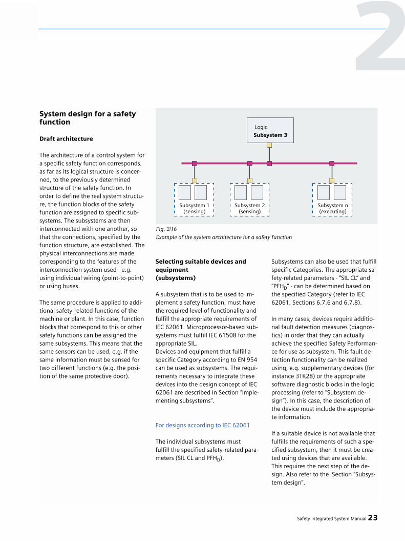
System design for a safetyfunction
Draft architecture
The architecture of a control system fora specific safety function corresponds,as far as its logical structure is concer-ned, to the previously determinedstructure of the safety function. Inorder to define the real system structu-re, the function blocks of the safetyfunction are assigned to specific sub-systems. The subsystems are theninterconnected with one another, sothat the connections, specified by thefunction structure, are established. Thephysical interconnections are madecorresponding to the features of theinterconnection system used - e.g.using individual wiring (point-to-point)or using buses.
The same procedure is applied to addi-tional safety-related functions of themachine or plant. In this case, functionblocks that correspond to this or othersafety functions can be assigned thesame subsystems. This means that thesame sensors can be used, e.g. if thesame information must be sensed fortwo different functions (e.g. the posi-tion of the same protective door).
Selecting suitable devices andequipment(subsystems)
A subsystem that is to be used to im-plement a safety function, must havethe required level of functionality andfulfill the appropriate requirements ofIEC 62061. Microprocessor-based sub-systems must fulfill IEC 61508 for theappropriate SIL. Devices and equipment that fulfill aspecific Category according to EN 954can be used as subsystems. The requi-rements necessary to integrate thesedevices into the design concept of IEC62061 are described in Section “Imple-menting subsystems”.
For designs according to IEC 62061
The individual subsystems mustfulfill the specified safety-related para-meters (SIL CL and PFHD).
Subsystems can also be used that fulfillspecific Categories. The appropriate sa-fety-related parameters - “SIL CL” and“PFHD” - can be determined based onthe specified Category (refer to IEC62061, Sections 6.7.6 and 6.7.8).
In many cases, devices require additio-nal fault detection measures (diagnos-tics) in order that they can actuallyachieve the specified Safety Performan-ce for use as subsystem. This fault de-tection functionality can be realizedusing, e.g. supplementary devices (forinstance 3TK28) or the appropriatesoftware diagnostic blocks in the logicprocessing (refer to “Subsystem de-sign”). In this case, the description ofthe device must include the appropria-te information.
If a suitable device is not available thatfulfills the requirements of such a spe-cified subsystem, then it must be crea-ted using devices that are available.This requires the next step of the de-sign. Also refer to the Section “Subsys-tem design”.
Safety Integrated System Manual 23
2
Fig. 2/16
Example of the system architecture for a safety function
Implementing the safety-related control system
A safety-related control system must beimplemented so that it fulfills all of therequirements corresponding to thedemanded SIL. The goal is to reducethe probability of systematic as well asrandom faults, which could result inthe dangerous failure of safety func-tions, to a sufficiently low level. Thefollowing aspects should be taken intoaccount
• Hardware integrity, i.e. restrictions regarding the architecture, (fault tolerance) and limited probability of failure
• Systematic integrity, i.e. require-ments regarding avoiding and controlling faults,
• Behavior when detecting a fault and software design/development
Hardware integrity
Every subsystem must have sufficientfault tolerance corresponding to the SILof the system. This depends on whatproportion of the faults go in the safedirection, referred to the probability of all possible faults of the subsystem.Potentially dangerous faults of a sub-system that can be detected in plentyof time as a result of the appropriatediagnostic functions, belong to thosefaults that go in a safe direction.
The permitted probability of failure of a safety function is limited by the SILdefined in the specifications (refer toFig. 2/17).
Systematic integrity
Measures, both to avoid systematicfaults and errors as well as to controlfaults remaining in the system, must beapplied:
Avoiding systematic faults
• The system must be installed according to the safety schedule
• The manufacturer's data of thedevices used must be carefully adhered to
• The electrical installation must be in compliance with IEC 60204-1 (7.2, 9.1.1 and 9.4.3)
• The design must be carefully checked to ensure its suitability and correctness
• A computer-supported tool must be used that uses pre-configured and tested elements.
Controlling systematic faults
• By disconnecting the energy feed• Measures to control temporary
subsystem failures or faults,e.g. due to power interruptions
• When connecting-up subsystems through a bus, the requirements of IEC 61508-2 regarding data communications must be fulfilled(e.g. PROFIsafe and ASIsafe)
• Faults in the connection (wiring) andthe subsystem interfaces must be detected and suitable responses initiated. For systematic handling,the interfaces and the wiring are considered as a components of the associated system.
Details, also refer to IEC 62061 6.4
Behavior when detecting a fault
If subsystem faults can result in hazar-dous failure of a safety-related func-tion, then these must be detected inplenty of time and an appropriate res-ponse initiated in order to avoid a ha-zard. The failure rates of the devicesused and the SIL of the system to beachieved (or the required PFH of thesubsystem) define to which level auto-matic fault detection (diagnostics) isnecessary.
How the system or the subsystem mustbehave when a fault is detected, de-pends on the fault tolerance of the as-sociated subsystem. If the detectedfault does not directly result in a failureof the safety-related function, i.e. faulttolerance > 0, then a fault response isnot immediately necessary, in fact onlyif the probability that a second fault oc-curs becomes too high (generally, thisinvolves hours or even days). If thefault that is detected directly results inthe safety-related function failing - i.e.a fault tolerance = 0 - then a fault res-ponse is immediately required, i.e. be-fore a hazard actually occurs.
24 Safety Integrated System Manual
2 – Specification and design of safety-related controls and machines

Safety Performance level reached
For every safety-related function it isspecified which Safety Performance itrequires. This must be fulfilled by thesafety-related control system.
For each safety-related function, itmust be determined as to which SafetyPerformance a system reaches. This isrealized using the architecture of thesystem and the safety-related parame-ters of the subsystems that are involvedin executing the safety-related functionbeing considered.
Design acc. to IEC 62061
The SIL that is achieved is limited bythe “SIL claim limit” of its subsystems.The lowest value of the subsystemsused limits the SIL of the system to thisvalue (the weakest link defines thestrength of the chain).
Systematic integrity: SIL SYS <= SIL CLlowest
Structural restrictions:SIL SYS <= SIL CLlowest
The safety requirements must be fulfil-led when connecting the subsystemswith one another. In this case, indivi-dual wiring connections are consideredas part of one or the two connectedsubsystems. For bus connections, thesend and receive hardware and soft-ware are part of the subsystems.
In addition to this principle suitability(claim limit), the probability of a dan-gerous failure of every safety-relatedfunction must be considered. Thisvalue is obtained by simply adding theprobabilities of failure of the subsys-tems involved in the function:
PFHD = PFHD1 + ...+ PFHDn
For bus connections, in addition, theprobability of possible data transmis-sion errors (PTE) must be added.
The value determined for a certainsafety function must be less (or thesame) as the value defined by the associated SIL.
Design according to EN 954
The category of the system reachedcorresponds to the category of itssubsystems.
If computer-based subsystems and buscommunications are used, then thesemust fulfill certain SIL acc. to 61508.The following assignment applies: Asubsystem suitable for SIL 1 can beused for Category 2 and, correspondin-gly, SIL 2 for Category 3 or SIL 3 forCategory 4.
Safety Integrated System Manual 25
2
SIL 1 SIL 2 SIL 3PFHD < 10–5 < 10–6 < 10–7
Probability of a dangerous fault per hour (PFHD)
Fig. 2/17
Limit values of the probabilities of dangerous faults of a safety function
System integration for allsafety-related functions
After the architectures for all of the sa-fety related functions have been desi-gned, then the next step is to integratethese function-specific architectures tocreate a full, safety-related control sys-tem.
There, where several safety-relatedfunctions have identical functionblocks, common subsystems can beused to implement them. For instance,only one safety PLC is required to im-plement the logic of all of the safetyfunctions. Or, in order to remove diffe-rent hazards (i.e. different safety func-tions) the condition of the same pro-tective door must be sensed, then thesensor required only has to be installedonce at this door.
This has no influence on the Safety In-tegrity, that has already been definedfor the individual functions. Only forelectromechanical devices (i.e. devicesthat are subject to wear), does thishave to be taken into account when de-termining their switching frequency.
Designing and implemen-ting subsystems
As an alternative to selecting an exis-ting subsystem, a subsystem can bemade-up of devices that alone do notfulfill the safety requirements but sothat the subsystem then achieves thenecessary Safety Performance. This is -in reference to the systematic integrityand the architectural constraints - theSIL claim limit (SIL CL) specified by therequired SIL of the safety-related func-tion. When designing the system archi-tecture, the maximum PFH values forthe individual system systems was defi-ned for the probability of the dange-rous random faults (PFHD).
IEC 62061: The safety performance of a subsystem is characterized by the SILCL determined by its architec-tural constraints (6.7.6), its SILCL dueto systematic integrity (6.7.9) and its probability of dangerous random hardware failure (6.7.8).
Generally, at least for SIL 2 and SIL 3,redundancy is required. Whether it beto achieve the necessary fault toleran-ce or to permit fault detection (dia-gnostics). However, it may also be necessary tocombine two devices to form a subsys-tem in order to reduce the probabilityof dangerous failure.
If, for example, for the access inter-locking of example (2) risk reducingmeasures SIL 2 or 3 (or Category 3 or4) is required, then simple door inter-locking functions or limit switches are not sufficient. For example, two tumbler mechanisms must be used to interlock every door and measuresto detect faults must be implemented.
The precise requirements when desi-gning and implementing subsystemsare described in IEC 62061, Sections6.7 and 6.8. The following descriptionprovides an overview.
Designing the subsystem architec-ture
A special subsystem architecture al-ways has to be designed, if, with thedevices intended for a specific task(subfunction “function block”) the ne-cessary Safety Integrity (Safety Perfor-mance) is not directly achieved. Gene-rally, the safety-related features andcharacteristics
• Low probability of failure• Fault tolerance, fault control• Fault detection
can only be achieved using special ar-chitectures. To what extend certainmeasures are required, depends on therequired Safety Performance (SafetyIntegrity).
26 Safety Integrated System Manual
2 – Specification and design of safety-related controls and machines

The subsystem is assigned a (sub) func-tion, the function block (e.g. keeping adoor interlocked). Initially, this functionblock (from the philosophy) is subdivi-ded into individual elements (functionblock elements), that can then be as-signed specific devices - the subsystemelements (refer to Fig. 2/18). Generally,the same function can be assigned twofunction block elements (the functionwas practically doubled). If these func-tion block elements are then imple-mented using specific devices, then the system has a simple fault tolerance(simple redundancy).
Safety Integrated System Manual 27
2
Fig. 2/18
Example for designing a subsystem architecture
If, in order to implement function block F3 “Interlock door A” of example (2) a simple tumbler mechanism is not sufficient in order to achieve the specified Safety Performance, then a subsystem with higher Safety Performance can beimplemented with the two following basic solutions.
a) A second door tumbler mechanism is connected in parallel z simple redundancy.
b) The door tumbler mechanism is supplemented by a door position monitoring function z fault detection
In example a) for homogeneous redundancy, the function block “interlockdoor A” is subdivided into two identical function block elements where eachelement has this function. In order to detect possible faults, in spite of this redundant arrangement, additional measures are required. In example b), the function block “interlock door A” is not subdivided any further. It is assigned one-to-one to a function block element. The additional door position monitoring is used for fault detection. It doesnot improve the door tumbler mechanism itself. However, the monitoring function can detect if the door tumbler mechanism fails and it can then initiate an appropriate response.
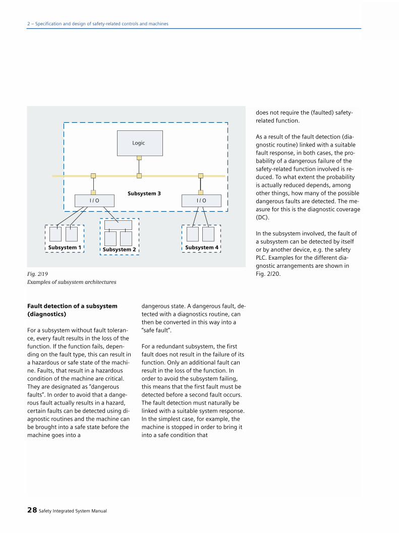
Fault detection of a subsystem (diagnostics)
For a subsystem without fault toleran-ce, every fault results in the loss of thefunction. If the function fails, depen-ding on the fault type, this can result ina hazardous or safe state of the machi-ne. Faults, that result in a hazardouscondition of the machine are critical.They are designated as “dangerousfaults”. In order to avoid that a dange-rous fault actually results in a hazard,certain faults can be detected using di-agnostic routines and the machine canbe brought into a safe state before themachine goes into a
dangerous state. A dangerous fault, de-tected with a diagnostics routine, canthen be converted in this way into a“safe fault”.
For a redundant subsystem, the firstfault does not result in the failure of itsfunction. Only an additional fault canresult in the loss of the function. Inorder to avoid the subsystem failing,this means that the first fault must bedetected before a second fault occurs.The fault detection must naturally belinked with a suitable system response.In the simplest case, for example, themachine is stopped in order to bring itinto a safe condition that
does not require the (faulted) safety-related function.
As a result of the fault detection (dia-gnostic routine) linked with a suitablefault response, in both cases, the pro-bability of a dangerous failure of thesafety-related function involved is re-duced. To what extent the probability is actually reduced depends, amongother things, how many of the possibledangerous faults are detected. The me-asure for this is the diagnostic coverage(DC).
In the subsystem involved, the fault ofa subsystem can be detected by itselfor by another device, e.g. the safetyPLC. Examples for the different dia-gnostic arrangements are shown in Fig. 2/20.
28 Safety Integrated System Manual
2 – Specification and design of safety-related controls and machines
Fig. 2/19
Examples of subsystem architectures

Systematic integrity of a subsys-tem
When designing and implementing asubsystem, measures must be made toboth avoid as well as control systematicfaults; for example:
• The devices used must be in compliance with InternationalStandards.
• The application conditionsspecified by the manufacturermust be fully complied with.
• The design and the materialsused must be able to stand-up to all of the ambient/environmental-conditions that can be expected.
• The behavior due to ambient/environmental effects must be able to be produced so that a safecondition of the machine can bemaintained.
• Online fault detection
• Positive actuation to initiatea protective measure.
The requirements described in IEC62061 only involve the design of elec-trical systems having a low degree ofcomplexity - i.e. no micro-processorbased subsystems. The required mea-sures apply the same for all SIL.
Probability of failure (PFHD) of asubsystem
The possible failures are subdividedinto “safe” or “hazardous” failures Inthis case, the hazardous failures of a subsystem are defined as follows.
Dangerous failure
Failure of an SRECS, a subsystem orsubsystem element with the potentialto cause a hazard or state that is notfunctional.Comment: Whether such a conditionoccurs or not can depend on the sys-tem architecture; In systems with mul-tiple channels to improve the safety, a dangerous hardware fault with lowprobability results in an overall dange-rous condition or in the failure of afunction.
This means, for example: For a redun-dant subsystem (i.e. fault tolerance 1),a fault in a channel is considered dan-gerous if it is potentially dangerous i.e.if there is no second channel then thiscould result in a dangerous machinestate.
For safety-related requirements, onlythe probability of dangerous failures is decisive. The so-called “safe faults”have a negative impact on the systemavailability, but do not result in anyhazard.
Safety Integrated System Manual 29
2
Fig. 2/20
Arrangement of diagnostic functions of subsystems

The probability of failure of a subsys-tem depends on the failure rates of thedevices that comprise the system, thearchitecture and the diagnostic measu-res. Formulas are described in the follo-wing for the most usual architectures.They apply under certain prerequisitesthat are detailed in IEC 62061:
For sufficiently low (1>> λ .T) failurerates (λ) of the subsystem elements,the following equation can be used:
λ = 1/MTTF
For electro-mechanical devices,the failure rate (λ) should be definedwhere the B10 value of the deviceand the operating cycles rate Cof the specified application areused in the following equation:
λ = 0.1*C/B10
The following terms are used in the formulas:
λ= λS + λD; whereby λS is the rate of non- hazardous failures and λD is the rate of hazardous failures.
PFHD= λD * 1h;Average probability of dangerousfailures within one hour
T2 : Diagnostics test interval
T1:Proof test interval or lifetime; the lower value is applied
Generally, only a specific percentage of the faults can be detected usingdiagnostic routines. The diagnosticscoverage specifies this percentage.
The diagnostics coverage can be ca-lculated using the following formula:
DC = S λDD / λDtotal
whereby λDD is the rate of detectedhazardous hardware faults and λDtotal the rates of dangeroushardware failures.
In order to determine the diagnosticcoverage, the individual faults (failuremodes) are weighted corresponding totheir relative frequency. Typical ratio numbers for a series of de-vices are specified in Table D.1 from IEC62061. When determining the fault co-verage for a subsystem, all of its com-ponents (subsystem elements) must beconsidered. These also include, forexample, the terminals and the wiringof the individual parts and components.
Structure without fault tolerance, withdiagnostics
With this structure (Fig. 2/21), the sub-system fails if any of its associated ele-ments fail; this means that a singlefault results in failure of the actual sa-fety-related function. However, this stilldoes not necessarily mean a dangerousloss of the safety-related function. De-pending on the fault type, the machinecan go into either a safe or dangerouscondition, i.e. the subsystemhas a “safe” or “dangerous” fault. If theprobability of dangerous faults (PFHS)is greater than that specified, thenthese faults must be detected using di-agnostic routines and a fault responseinitiated before a hazard can actuallyoccur. This means that dangerousfaults become safe faults and in turn,the probability of a dangerous failureof the subsystem is reduced. As a con-sequence - the specified failure proba-bility may be able to be reached.
30 Safety Integrated System Manual
2 – Specification and design of safety-related controls and machines
Fig. 2/21
Logical structure of a subsystem without fault tolerance and diagnostics
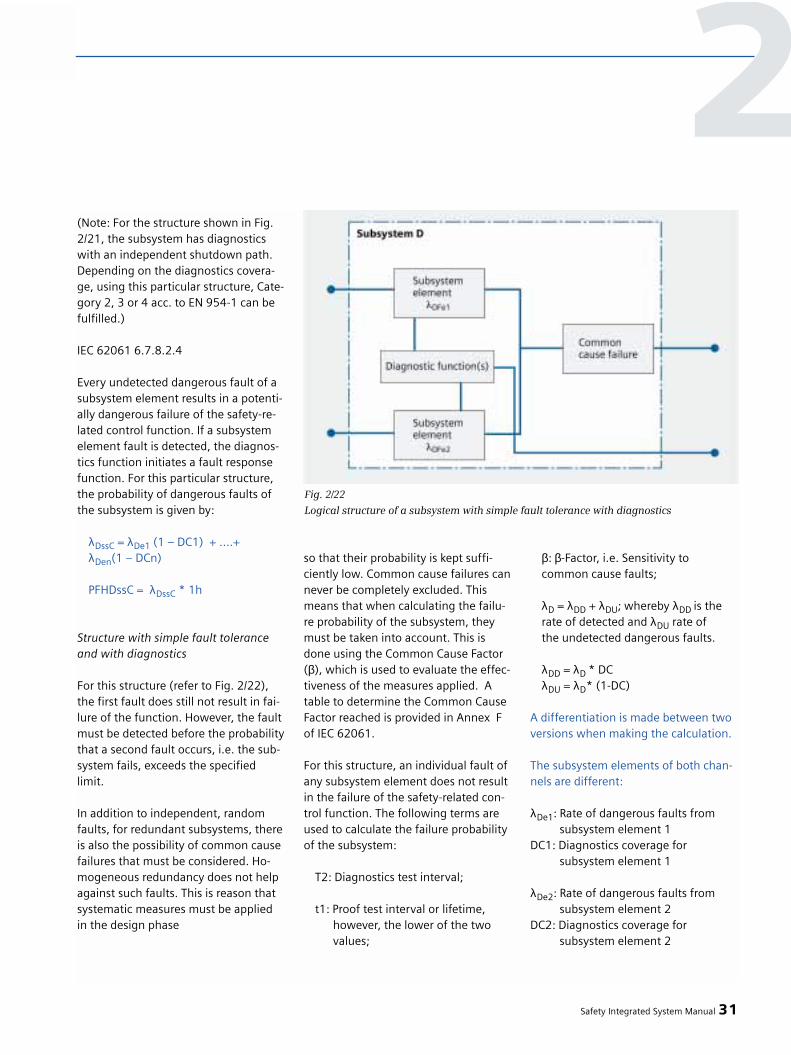
(Note: For the structure shown in Fig.2/21, the subsystem has diagnosticswith an independent shutdown path.Depending on the diagnostics covera-ge, using this particular structure, Cate-gory 2, 3 or 4 acc. to EN 954-1 can befulfilled.)
IEC 62061 6.7.8.2.4
Every undetected dangerous fault of asubsystem element results in a potenti-ally dangerous failure of the safety-re-lated control function. If a subsystemelement fault is detected, the diagnos-tics function initiates a fault responsefunction. For this particular structure,the probability of dangerous faults ofthe subsystem is given by:
λDssC = λDe1 (1 – DC1) + ....+ λDen(1 – DCn)
PFHDssC = λDssC * 1h
Structure with simple fault toleranceand with diagnostics
For this structure (refer to Fig. 2/22),the first fault does still not result in fai-lure of the function. However, the faultmust be detected before the probabilitythat a second fault occurs, i.e. the sub-system fails, exceeds the specifiedlimit.
In addition to independent, randomfaults, for redundant subsystems, thereis also the possibility of common causefailures that must be considered. Ho-mogeneous redundancy does not helpagainst such faults. This is reason thatsystematic measures must be appliedin the design phase
so that their probability is kept suffi-ciently low. Common cause failures cannever be completely excluded. Thismeans that when calculating the failu-re probability of the subsystem, theymust be taken into account. This isdone using the Common Cause Factor(β), which is used to evaluate the effec-tiveness of the measures applied. Atable to determine the Common CauseFactor reached is provided in Annex Fof IEC 62061.
For this structure, an individual fault ofany subsystem element does not resultin the failure of the safety-related con-trol function. The following terms areused to calculate the failure probabilityof the subsystem:
T2: Diagnostics test interval;
t1: Proof test interval or lifetime,however, the lower of the two values;
β: β-Factor, i.e. Sensitivity tocommon cause faults;
λD = λDD + λDU; whereby λDD is the rate of detected and λDU rate ofthe undetected dangerous faults.
λDD = λD * DCλDU = λD* (1-DC)
A differentiation is made between twoversions when making the calculation.
The subsystem elements of both chan-nels are different:
λDe1: Rate of dangerous faults fromsubsystem element 1
DC1: Diagnostics coverage for subsystem element 1
λDe2: Rate of dangerous faults fromsubsystem element 2
DC2: Diagnostics coverage for subsystem element 2
Safety Integrated System Manual 31
2
Fig. 2/22
Logical structure of a subsystem with simple fault tolerance with diagnostics
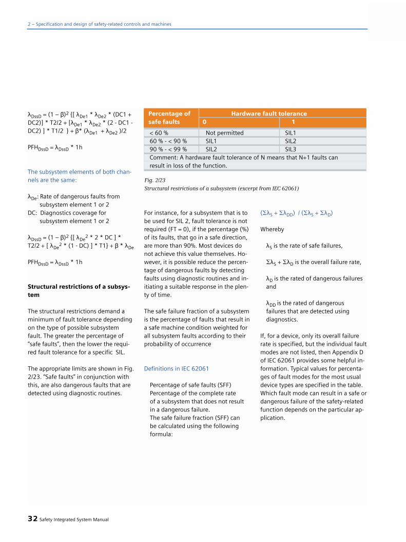
λDssD = (1 – β)2 {[ λDe1 * λDe2 * (DC1 +DC2)] * T2/2 + [λDe1 * λDe2 * (2 - DC1 -DC2) ] * T1/2 } + β* (λDe1 + λDe2 )/2
PFHDssD = λDssD * 1h
The subsystem elements of both chan-nels are the same:
λDe: Rate of dangerous faults fromsubsystem element 1 or 2
DC: Diagnostics coverage for subsystem element 1 or 2
λDssD = (1 – β)2 {[ λDe2 * 2 * DC ] *
T2/2 + [ λDe2 * (1 - DC) ] * T1} + β * λDe
PFHDssD = λDssD * 1h
Structural restrictions of a subsys-tem
The structural restrictions demand aminimum of fault tolerance dependingon the type of possible subsystemfault. The greater the percentage of“safe faults”, then the lower the requi-red fault tolerance for a specific SIL.
The appropriate limits are shown in Fig.2/23. “Safe faults” in conjunction withthis, are also dangerous faults that aredetected using diagnostic routines.
For instance, for a subsystem that is tobe used for SIL 2, fault tolerance is notrequired (FT = 0), if the percentage (%)of its faults, that go in a safe direction,are more than 90%. Most devices donot achieve this value themselves. Ho-wever, it is possible reduce the percen-tage of dangerous faults by detectingfaults using diagnostic routines and in-itiating a suitable response in the plen-ty of time.
The safe failure fraction of a subsystemis the percentage of faults that result ina safe machine condition weighted forall subsystem faults according to theirprobability of occurrence
Definitions in IEC 62061
Percentage of safe faults (SFF)Percentage of the complete rate of a subsystem that does not resultin a dangerous failure.The safe failure fraction (SFF) can be calculated using the followingformula:
(SλS + SλDD) / (SλS + SλD)
Whereby
λS is the rate of safe failures,
SλS + SλD is the overall failure rate,
λD is the rated of dangerous failuresand
λDD is the rated of dangerousfailures that are detected usingdiagnostics.
If, for a device, only its overall failurerate is specified, but the individual faultmodes are not listed, then Appendix Dof IEC 62061 provides some helpful in-formation. Typical values for percenta-ges of fault modes for the most usualdevice types are specified in the table.Which fault mode can result in a safe ordangerous failure of the safety-relatedfunction depends on the particular ap-plication.
32 Safety Integrated System Manual
2 – Specification and design of safety-related controls and machines
< 60 % Not permitted SIL160 % - < 90 % SIL1 SIL290 % - < 99 % SIL2 SIL3Comment: A hardware fault tolerance of N means that N+1 faults can result in loss of the function.
Percentage of Hardware fault tolerancesafe faults 0 1
Fig. 2/23
Structural restrictions of a subsystem (excerpt from IEC 62061)

Selecting the devices
In order to use devices in safety-relatedsubsystems, their features, characteris-tics and the application conditionsmust be clearly defined.
In order to described the safety-specificfeatures and characteristics, the follo-wing data is also required:
• The failure rate and the possiblefault modes.Note: For electro-mechanicaldevices, the failure rate is specified as B10 value. (The B10 value isthe number of operating cycles after which 10% of the devices have failed.Also refer to IEC 6810-2). Due to thefrequency of individual fault modesalso refer to IEC 62061 Appendix D.
• Features and characteristicsthat can be used for diagnostics (e.g. positively-driven auxiliary contacts).
Implementing subsystems
Every subsystem must be implementedas was defined in the design phase forits specified features and ambient con-ditions. If the subsystem is also imple-mented corresponding to the require-ments in IEC 62061 to avoid and con-trol systematic faults, then regardingits “systematic integrity” it is suitablefor applications in safety functions up toSIL 3. It fulfills a SIL claim limit SILCL = 3.
Safety Integrated System Manual 33
2

34 Safety Integrated System Manual
2 – Specification and design of safety-related controls and machines
Objective: A safety-related (control)system must correctly execute a safety-related function. When a fault deve-lops, it must respond so that the ma-chine or plant either remains in a safecondition or is brought into a safecondition.
Determining the necessarySafety Performance (SafetyIntegrity)
The requirements placed on the safety-related functions are determined usingthe risk assessment process (refer toChapter 2.3 “Does the protective mea-sure depend on a control?”).EN 954-1 defines a Category for theDraft and the follow-on (subsequent)Standard ISO 13849-1 (rev) specifies arequired Performance Level PLr. Alsorefer to Chapter 2.3 “Does the protecti-ve measure depend on a control?”.
Process to design the safety-related parts of a control
The categories according to EN 954-1refer, to the same degree, to the sys-tem (safety-related function) and itssubsystems (safety-related parts of acontrol). When implementing the con-trol according to EN 954, the sameprinciple of structuring the safety-rela-ted system can be applied as describedin IEC 62061.
Such a subsystem that is demarcated insuch a way must then fulfill the Cate-gory that is specified for the protectivefunction. The requirements of the asso-ciated category also apply for the wi-ring between these subsystems.
When compared with IEC 62061, forthe Draft according to EN 954, a cate-gory is specified instead of SIL CL (SILclaim limit). The quantitative analysisof the probability of dangerous failuresis eliminated.
Fig. 2/24
Iterative process to design the safety-related parts of controls (SRP/CS)
2.6 Designing andimplementing safety-related parts of a controlaccording to EN 954-1(ISO 13849-1 (rev))

On the other hand, in ISO 13849-1(rev), for the draft, in addition to thecategories, the Performance Level PLr isintroduced as the quantitative level forthe probability of failure.
The iterative process to design the safe-ty-related parts of controls (SRP/CS) isshown in Fig. 2/24:
Implementing a safety-rela-ted function
The architecture depends on the Cate-gory required or the required Perfor-mance Level PLr.
Draft according to EN 954
The Category of the system reachedcorresponds to the Category of thesubsystems used.
The decisive basis in EN 954-1 is thefault detection and the fault controlthat can be implemented with one Ca-tegory. This is because only if a fault is detec-ted, can a response be explicitly initia-ted: The quality of the fault detectiondefines the measure of the fault con-trol and therefore implicitly defines thefault control measures (architecturaldraft).
Comment: If computer-based subsys-tems and bus communications areused, then these must fulfill a specificSIL acc. to 61508. In this case, the fol-lowing assignment applies: A subsys-tem, suitable for SIL 1, can be used forCategory 2 and appropriately, SIL 2 forCategory 3 or SIL 3 for Category 4.
Draft according to ISO 13849-1(rev)
The draft concept of ISO 13849-1 (rev)is based on special predefined architec-tures of the safety-related parts of thecontrol.
A safety function can comprise one orseveral safety-related parts of a control(SRP/CS).
A safety-related function can also be anoperating function, e.g. a two-hand cir-cuit to initiate a process.
A typical safety-related function com-prises the following safety-related partsof a control:
• Input (SRP/CSa)• Logic / processing (SRP/CSb)
• Output / power transmissionelement (SRP/CSc)
• Connections (iab, iac) (e.g. electrical, optical)
Comment: Safety-related componentscomprise one or several component(s);Components can comprise one or seve-ral element(s).
All connection elements arecontained in safety-related parts.
If the safety functions of the controlhave been defined, the safety-relatedparts of the control must be identified.It is also important to assess their rolein the process regarding reducing risk(ISO 12100).
Safety Integrated System Manual 35
2
Fig. 2/25
Arrangement of a typical safety-related function

Drafting and implementingcategories
The requirements placed on thecategories are shown simplified in ISO 13849-1(rev):
36 Safety Integrated System Manual
2 – Specification and design of safety-related controls and machines
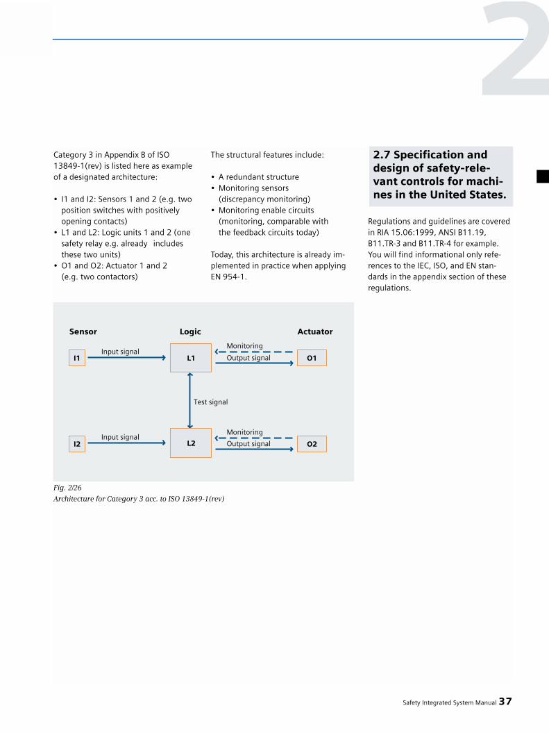
Category 3 in Appendix B of ISO13849-1(rev) is listed here as exampleof a designated architecture:
• I1 and I2: Sensors 1 and 2 (e.g. twoposition switches with positively opening contacts)
• L1 and L2: Logic units 1 and 2 (onesafety relay e.g. already includes these two units)
• O1 and O2: Actuator 1 and 2 (e.g. two contactors)
The structural features include:
• A redundant structure• Monitoring sensors
(discrepancy monitoring)• Monitoring enable circuits
(monitoring, comparable with the feedback circuits today)
Today, this architecture is already im-plemented in practice when applyingEN 954-1.
Regulations and guidelines are coveredin RIA 15.06:1999, ANSI B11.19,B11.TR-3 and B11.TR-4 for example.You will find informational only refe-rences to the IEC, ISO, and EN stan-dards in the appendix section of theseregulations.
Safety Integrated System Manual 37
2
Fig. 2/26
Architecture for Category 3 acc. to ISO 13849-1(rev)
2.7 Specification anddesign of safety-rele-vant controls for machi-nes in the United States.


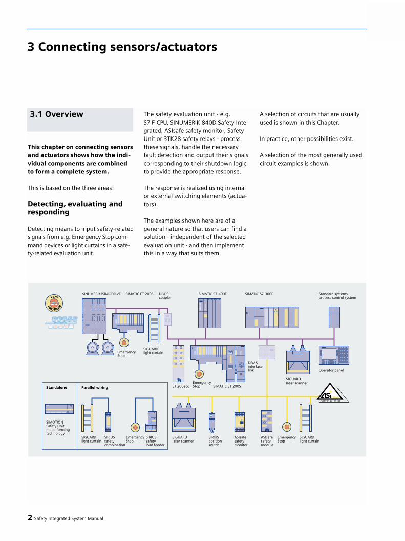
This chapter on connecting sensorsand actuators shows how the indi-vidual components are combinedto form a complete system.
This is based on the three areas:
Detecting, evaluating andresponding
Detecting means to input safety-relatedsignals from e.g. Emergency Stop com-mand devices or light curtains in a safe-ty-related evaluation unit.
The safety evaluation unit - e.g. S7 F-CPU, SINUMERIK 840D Safety Inte-grated, ASIsafe safety monitor, SafetyUnit or 3TK28 safety relays - processthese signals, handle the necessaryfault detection and output their signalscorresponding to their shutdown logicto provide the appropriate response.
The response is realized using internalor external switching elements (actua-tors).
The examples shown here are of ageneral nature so that users can find asolution - independent of the selectedevaluation unit - and then implementthis in a way that suits them.
A selection of circuits that are usuallyused is shown in this Chapter.
In practice, other possibilities exist.
A selection of the most generally usedcircuit examples is shown.
2 Safety Integrated System Manual
3 Connecting sensors/actuators
3.1 Overview
Sensors and actuators are connec-ted to various evaluation units.
The following versions are possiblewhen using Safety Integrated:
Conventional solution
• SIRIUS Safety Integrated- 3TK28.. safety relays- 3RA7.. safety load feeders- 3RG7848.. safety evaluation
units for optical safety-related sensors
Bus-based solutions
ASIsafe
• SIRIUS Safety Integrated- 3RK11.. safety monitor- K45F and K60F compact modules
(IP67) - Directly connecting electro-
mechanical sensors (IP67)- Slimline modules S22.5F (IP20)
• Optical safety sensors are directly connected
PROFIsafe
• SIMATIC Safety Integrated- CPU S7-300 F- CPU S7-400 F- ET 200S, ET 200M and
ET 200eco I/O
• SIRIUS Safety Integrated- ET 200S Motorstarter
• SINUMERIK- Via separate input/output hardware
I/O from the PLC and NC or via PROFIsafe with the ET 200S andET 200eco I/O modules together with the SINUMERIK 840D/ SIMODRIVE 611D control
• Optical safety sensors aredirectly connected
Possible sensor versions
1. NC/NC contacts (equivalent) q (positively-openingcontacts)This version is mainly used to shutdown - e.g. for an Emergency Stop orprotective door monitoring.
2. NO/NO contact (equivalent)The version is predominantly used topower-up, e.g. for setting-up opera-tion.
3. NC/NO contacts (non-equivalent)The version is predominantly used to shut down and power-up, e.g. two-hand operator control
Safety Integrated System Manual 3
33.2 Features
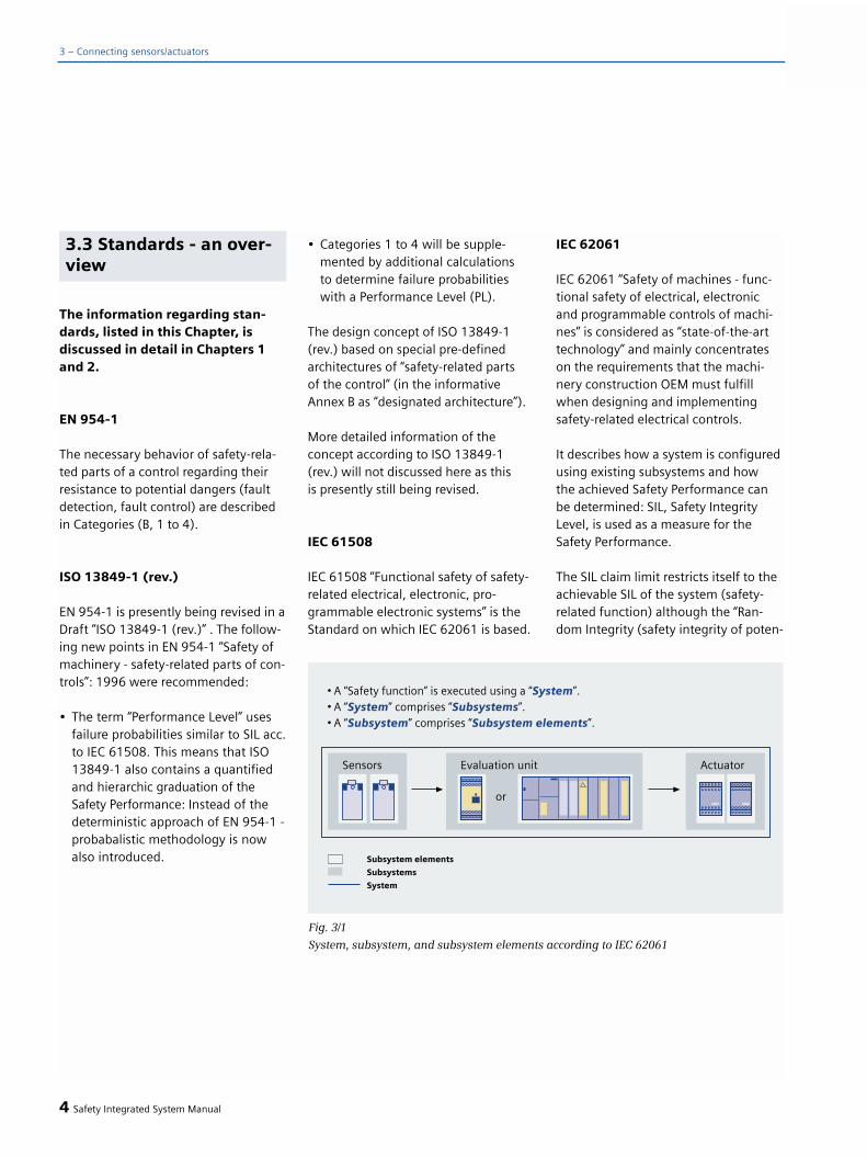
The information regarding stan-dards, listed in this Chapter, isdiscussed in detail in Chapters 1and 2.
EN 954-1
The necessary behavior of safety-rela-ted parts of a control regarding theirresistance to potential dangers (faultdetection, fault control) are describedin Categories (B, 1 to 4).
ISO 13849-1 (rev.)
EN 954-1 is presently being revised in aDraft “ISO 13849-1 (rev.)” . The follow-ing new points in EN 954-1 “Safety ofmachinery - safety-related parts of con-trols”: 1996 were recommended:
• The term “Performance Level” uses failure probabilities similar to SIL acc.to IEC 61508. This means that ISO 13849-1 also contains a quantified and hierarchic graduation of the Safety Performance: Instead of the deterministic approach of EN 954-1 -probabalistic methodology is now also introduced.
• Categories 1 to 4 will be supple-mented by additional calculationsto determine failure probabilities with a Performance Level (PL).
The design concept of ISO 13849-1(rev.) based on special pre-definedarchitectures of “safety-related parts of the control” (in the informativeAnnex B as “designated architecture”).
More detailed information of the concept according to ISO 13849-1 (rev.) will not discussed here as this is presently still being revised.
IEC 61508
IEC 61508 “Functional safety of safety-related electrical, electronic, pro-grammable electronic systems” is theStandard on which IEC 62061 is based.
IEC 62061
IEC 62061 “Safety of machines - func-tional safety of electrical, electronicand programmable controls of machi-nes” is considered as “state-of-the-arttechnology” and mainly concentrateson the requirements that the machi-nery construction OEM must fulfillwhen designing and implementingsafety-related electrical controls.
It describes how a system is configuredusing existing subsystems and how the achieved Safety Performance canbe determined: SIL, Safety IntegrityLevel, is used as a measure for theSafety Performance.
The SIL claim limit restricts itself to theachievable SIL of the system (safety-related function) although the “Ran-dom Integrity (safety integrity of poten-
4 Safety Integrated System Manual
3 – Connecting sensors/actuators
Fig. 3/1
System, subsystem, and subsystem elements according to IEC 62061
3.3 Standards - an over-view

tially dangerous, random hardwarefailures)” achieves SIL 2.
The application in Fig. 3/2 comprisesthe following subsystems:
• Detecting (a position switch, 1-channel)
• Evaluating (3TK28.., with diagnostics)
• Responding (two contactors)
The PFHD values that are used in thecalculation are only an example and donot represent actual values.
Principle approach when applyingIEC 62061:
• The 1st requirement (SIL suitabi-lity claim limit of the subsystems)limits the achievable Safety Perfor-mance of the system.
SILSYSTEM <= SILCLlowest
Every subsystem is only suitable up to a specific SIL as result of its systematicproperties and features. This valuelimits the possible SIL of the system(weakest link in the chain).
• The 2nd requirement (hardware safety integrity) is the limit of the probability of “dangerous faults” for the complete safety-related function;this means that the sum of all of the failure probabilities of all of the sub-systems may not exceed the PFHDof the required SIL.
The failure probability of the contactors(the electro-mechanical subsystem “ac-tuator”) is defined using a simplifiedcalculation with the B10 values accor-ding to IEC 62061.
The following equation applies for thesystem:
PFHD(system) = PFHD(detecting) + PFHD(eva-
luating) + PFHD(responding) + PTE <= requi-red failure probability of the system
For safety-related communications, the probability of possible data transfererrors (PTE) must be added.
• The 3rd request (selection and interconnection) - when selectingand interconnecting the subsystems,the appropriate requirements of IEC 62061 6.4 must be fulfilled - “requi-rements relating to systematic safetyintegrity”.
Safety Integrated System Manual 5
3
Fig. 3/2Application example for an application according to IEC 62061

General information
Principle, Category B acc. to EN 954-1
The safety-related parts of machinecontrols and/or their protective devi-ces and their components must be designed, constructed and selected in compliance with the applicable Standards so that they can withstandthe ambient effects that are expected.
With the continually increasing inter-meshing and globalization of the eco-nomy, a specific minimum standard is defined in the EU Economic Commu-nity with Category B.
Requirement
The control must be designed so that itcan withstand the ambient effects thatare to be expected.
System behavior
A fault that occurs can result in the lossof the safety-related function.
Principle
Achieving the level of safety is espe-cially characterized by the selection of components, e.g. protected againstspray water, protected against dust,protected against vibration etc.
Description and additional infor-mation
Requirement
The requirements of B must be fulfilled;in addition, safety-related, proven com-ponents and principles must be applied.A component has proven itself if, in thepast it was widely used with successfulresults.
System behavior
The occurrence of a fault can result inloss of the safety-related function. Theprobability of a failure in Category 1 islower than in Category B.
Principle
Selecting componentsSensors: e.g. acc. to EN 954-1Actuators: “proven components” (e.g. contactors/circuit-breakers)
6 Safety Integrated System Manual
3 – Connecting sensors/actuators
Fig. 3/3
Principle, Category 1 acc. to EN 954-1 using a protective door monitoring function as an
example
3.4 Connecting sensors/actuators
Principle, Category 1 acc. to EN 954-1
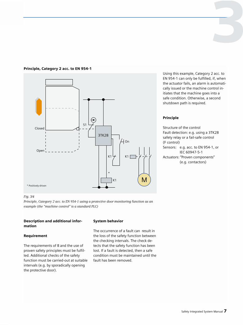
Description and additional infor-mation
Requirement
The requirements of B and the use ofproven safety principles must be fulfil-led. Additional checks of the safetyfunction must be carried-out at suitableintervals (e.g. by sporadically openingthe protective door).
System behavior
The occurrence of a fault can result inthe loss of the safety function betweenthe checking intervals. The check de-tects that the safety function has beenlost. If a fault is detected, then a safecondition must be maintained until thefault has been removed.
Using this example, Category 2 acc. toEN 954-1 can only be fulfilled, if, whenthe actuator fails, an alarm is automati-cally issued or the machine control in-itiates that the machine goes into asafe condition. Otherwise, a secondshutdown path is required.
Principle
Structure of the controlFault detection: e.g. using a 3TK28 safety relay or a fail-safe control (F control)Sensors: e.g. acc. to EN 954-1, or
IEC 60947-5-1Actuators: “Proven components”
(e.g. contactors)
Safety Integrated System Manual 7
3
Fig. 3/4
Principle, Category 2 acc. to EN 954-1 using a protective door monitoring function as an
example (the “machine control” is a standard PLC)
Principle, Category 2 acc. to EN 954-1

3 – Connecting sensors/actuators
Description and additional infor-mation
Requirement
The requirements of B and the use of proven safety components must be fulfilled. In Category 3, all safety-
related parts must be designed so that a simple fault cannot result in theloss of the safety function. The singlefault must be detected the next timethat the safety function is called on.This requirement can, e.g. be achieved with redundancy (refer to Fig. 3/5).
System behavior
If a single fault occurs, the safety func-tion is always maintained. Several, butnot all faults will be detected. An accu-mulation of undetected faults can re-sult in the loss of the safety function.
Principle
Control structureFault detection: e.g. using a 3TK28safety relay or a fail-safe controlF-controlSensors: Redundantly configuredActuators: Redundantly configured
8 Safety Integrated System Manual
Fig. 3/5
Principle, Category 3 acc. to EN 954-1 using a protective door monitoring function as an
example
Principle, Category 3 acc. to EN954-1
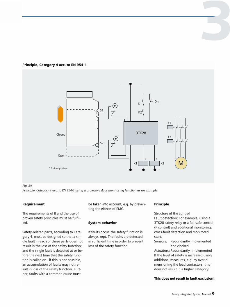
Requirement
The requirements of B and the use ofproven safety principles must be fulfil-led.
Safety-related parts, according to Cate-gory 4, must be designed so that a sin-gle fault in each of these parts does notresult in the loss of the safety function;and the single fault is detected at or be-fore the next time that the safety func-tion is called on - if this is not possible,an accumulation of faults may not re-sult in loss of the safety function. Furt-her, faults with a common cause must
be taken into account, e.g. by preven-ting the effects of EMC.
System behavior
If faults occur, the safety function isalways kept. The faults are detected in sufficient time in order to preventloss of the safety function.
Principle
Structure of the controlFault detection: For example, using a3TK28 safety relay or a fail-safe control(F control) and additional monitoring,cross-fault detection and monitoredstart.Sensors: Redundantly implemented
and clockedActuators: Redundantly implementedIf the level of safety is increased usingadditional measures, e.g. by over-di-mensioning the load contactors, thisdoes not result in a higher category!
This does not result in fault exclusion!
Safety Integrated System Manual 9
3
Fig. 3/6
Principle, Category 4 acc. to EN 954-1 using a protective door monitoring function as an example
Principle, Category 4 acc. to EN 954-1

Manual, monitored start andautostart(EN 954-1, EN 60204-1)
Is possible with various safety-relatedcomponents (subsystem evaluation).
A safety relay can either be manuallystarted - which can be monitored - orautomatically started.
For a manual or monitored start, anenable signal is generated by pressingthe ON button, after the input imagehas been checked and after the safetyrelay has been successfully tested.This function is also known as staticoperation and is specified for EmergencyStop command devices (EN 60204-1,conscious action).
Contrary to a manual start, the monito-red start evaluates the signal change ofan ON button. This means that it is notpossible to manipulate the operation ofthe ON button.
For an automatic start, an enable sig-nal is generated without any manualagreement, but after the input image is checked and the safety relay success-fully tested. The function is also knownas dynamic operation and is not per-missible for Emergency Stop equip-ment and command devices.
Mechanically isolating protective devi-ces (e.g. guards that cannot be enter-ed) operate with an automatic start.
Comment: A manual start can be im-plemented with a safety relay withautomatic start, if, in addition to thepositively-driven contacts of the loadcontactors, an ON button is connectedin series in the feedback circuit (refer to Fig. 3/11).
A manual start is possible up toCategory 3 according to EN 954-1.
A manual start is permissible for anEmergency Stop command device up to Category 3 according to EN 954-1(ISO 13849-1 rev.).
For Category 4 a monitored startmust be used.
For Category 4 according to EN 954-1(ISO 13849-1 rev.), for an EmergencyStop command device, a monitoredstart is required: Unexpected startingmust be absolutely excluded.
Description and additional infor-mation
Emergency Stop monitoring functionsmay always be connected in series: Itcan be excluded that when the Emer-gency Stop command device is pressed,that it simultaneously fails.
10 Safety Integrated System Manual
3 – Connecting sensors/actuators
Fig. 3/7
Series circuit up to Category 4
acc. to EN 954-1 using an Emergency Stop
monitoring function as an example
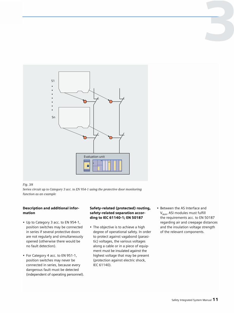
Description and additional infor-mation
• Up to Category 3 acc. to EN 954-1,position switches may be connectedin series if several protective doors are not regularly and simultaneously opened (otherwise there would be no fault detection).
• For Category 4 acc. to EN 951-1, position switches may never beconnected in series, because everydangerous fault must be detected(independent of operating personnel).
Safety-related (protected) routing,safety-related separation accor-ding to IEC 61140-1; EN 50187
• The objective is to achieve a high degree of operational safety. In orderto protect against vagabond (parasi-tic) voltages, the various voltages along a cable or in a piece of equip-ment must be insulated against the highest voltage that may be present (protection against electric shock, IEC 61140).
• Between the AS Interface andVaux, ASI modules must fulfill the requirements acc. to EN 50187 regarding air and creepage distancesand the insulation voltage strength of the relevant components.
Safety Integrated System Manual 11
3
Fig. 3/8
Series circuit up to Category 3 acc. to EN 954-1 using the protective door monitoring
function as an example

Conventionally connectingsensors without using safe-ty-related communicationsvia fieldbuses
Description and additional infor-mation
Mechanical switches such as EmergencyStop command devices, position swit-ches or light curtains, light grids andlaser scanners are used for detection.
SIRIUS 3TK28 safety relays are used toevaluate signals. The safety 3RA7 loadfeeder includes, in addition to the3TK28 safety relay, redundant loadcontactors. These can safely shut downan actuator as single unit in Category 4according to EN 954-1.
A response is directly implementedusing discrete switching devices (con-tactors) or using PMD-Fxx modules inan ET 200S station in conjunction withmotor starters (refer to Fig. 3/17) orfrequency converters.
The application shown in Fig. 3/10comprises the following subsystems:
• Detecting (two position switcheseach 1 channel)
• Evaluating (3TK28.., with diagnos-tics)
• Responding (two contactors)
The PFHD values used for the calcula-tion are only as an example.
12 Safety Integrated System Manual
3 – Connecting sensors/actuators
Fig. 3/9
Group diagram - directly connecting sensors (conventional)
Fig. 3/10
Example of an application according to IEC 62061 that is conventionally connected
without using safety-related communications
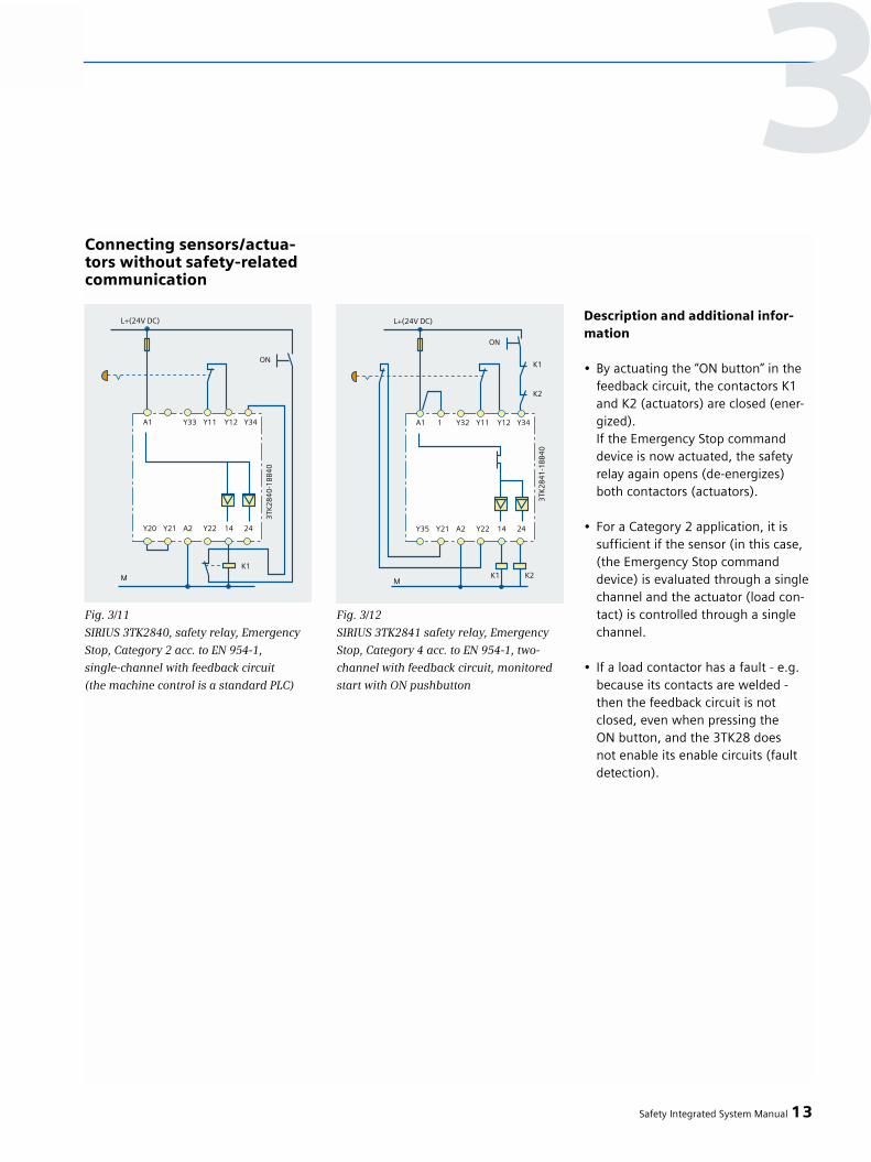
Connecting sensors/actua-tors without safety-relatedcommunication
Description and additional infor-mation
• By actuating the “ON button” in the feedback circuit, the contactors K1 and K2 (actuators) are closed (ener-gized).If the Emergency Stop command device is now actuated, the safety relay again opens (de-energizes) both contactors (actuators).
• For a Category 2 application, it issufficient if the sensor (in this case,(the Emergency Stop command device) is evaluated through a single channel and the actuator (load con-tact) is controlled through a single channel.
• If a load contactor has a fault - e.g.because its contacts are welded - then the feedback circuit is not closed, even when pressing theON button, and the 3TK28 does not enable its enable circuits (fault detection).
Safety Integrated System Manual 13
3
Fig. 3/11
SIRIUS 3TK2840, safety relay, Emergency
Stop, Category 2 acc. to EN 954-1,
single-channel with feedback circuit
(the machine control is a standard PLC)
Fig. 3/12
SIRIUS 3TK2841 safety relay, Emergency
Stop, Category 4 acc. to EN 954-1, two-
channel with feedback circuit, monitored
start with ON pushbutton
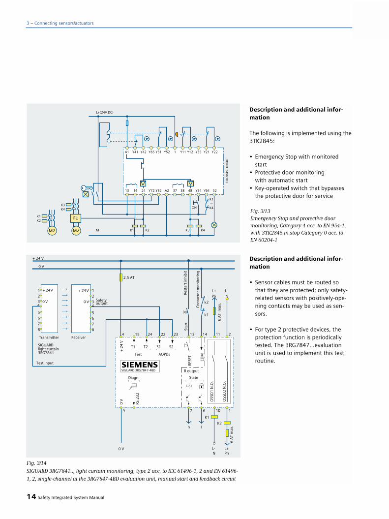
Description and additional infor-mation
The following is implemented using the3TK2845:
• Emergency Stop with monitored start
• Protective door monitoringwith automatic start
• Key-operated switch that bypassesthe protective door for service
Description and additional infor-mation
• Sensor cables must be routed sothat they are protected; only safety-related sensors with positively-ope-ning contacts may be used as sen-sors.
• For type 2 protective devices, the protection function is periodically tested. The 3RG7847…evaluation unit is used to implement this test routine.
14 Safety Integrated System Manual
3 – Connecting sensors/actuators
Fig. 3/13Emergency Stop and protective door monitoring, Category 4 acc. to EN 954-1,with 3TK2845 in stop Category 0 acc. to EN 60204-1
Fig. 3/14
SIGUARD 3RG7841.., light curtain monitoring, type 2 acc. to IEC 61496-1, 2 and EN 61496-
1, 2, single-channel at the 3RG7847-4BD evaluation unit, manual start and feedback circuit

Safety Integrated System Manual 15
Fig. 3/15SIGUARD 3RG7842.., light curtain/grid monitoring, type 4 acc. to IEC 61496-1, 2, two-channelconnected to a SIRIUS 3TK284.., stop Category 0, acc. to EN 60204-1, autostart and feed-back circuit
Fig. 3/16
SIGUARD LS4 laser scanner, type 3 acc. to IEC 61496-1, 2 or EN 61496-1, 2 two channel, connected to a 3RG7847-4BB, (evaluation unit)
laser scanner configured for manual start, feedback circuit monitoring using a 3RG7847-4BB
3

Description and additional infor-mation
• If the Emergency Stop pushbutton, connected through two channels at the 3TK2823 is operated, then the actuators are shut down. This is rea-lized by the 3TK2823 shutting down the motor starter supply voltage via the PMD module. In this case, safety is guaranteed by the 3TK2823.
• The two PM-X modules and theF kits are required to evaluate and monitor the feedback circuit.
• The 3TK2823 evaluates the feedbackcircuit.
16 Safety Integrated System Manual
3 – Connecting sensors/actuators
Fig. 3/17
ET 200S Motorstarter Solution Local with external Emergency Stop monitoring, Category 2 acc. to EN 954-1
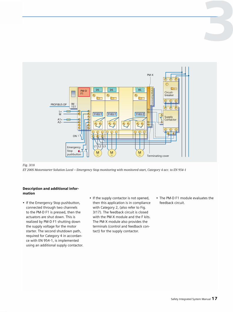
Description and additional infor-mation
• If the Emergency Stop pushbutton, connected through two channels to the PM-D F1 is pressed, then the actuators are shut down. This is realized by PM-D F1 shutting down the supply voltage for the motorstarter. The second shutdown path,required for Category 4 in accordan-ce with EN 954-1, is implementedusing an additional supply contactor.
• If the supply contactor is not opened,then this application is in compliancewith Category 2, (also refer to Fig. 3/17). The feedback circuit is closed with the PM-X module and the F kits.The PM-X module also provides the terminals (control and feedback con-tact) for the supply contactor.
• The PM-D F1 module evaluates the feedback circuit.
Safety Integrated System Manual 17
Fig. 3/18
ET 200S Motorstarter Solution Local – Emergency Stop monitoring with monitored start, Category 4 acc. to EN 954-1
3
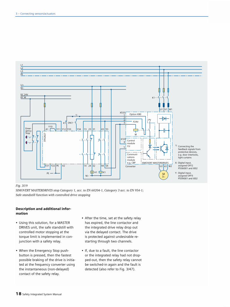
Description and additional infor-mation
• Using this solution, for a MASTERDRIVES unit, the safe standstill with controlled motor stopping at the torque limit is implemented in con-junction with a safety relay.
• When the Emergency Stop push-button is pressed, then the fastest possible braking of the drive is initia-ted at the frequency converter usingthe instantaneous (non-delayed) contact of the safety relay.
• After the time, set at the safety relay has expired, the line contactor and the integrated drive relay drop out via the delayed contact. The drive is protected against undesirable re-starting through two channels.
• If, due to a fault, the line contactoror the integrated relay had not drop-ped-out, then the safety relay cannotbe switched-in again and the fault isdetected (also refer to Fig. 3/47).
18 Safety Integrated System Manual
3 – Connecting sensors/actuators
Fig. 3/19
SIMOVERT MASTERDRIVES stop Category 1, acc. to EN 60204-1, Category 3 acc. to EN 954-1;
Safe standstill function with controlled drive stopping
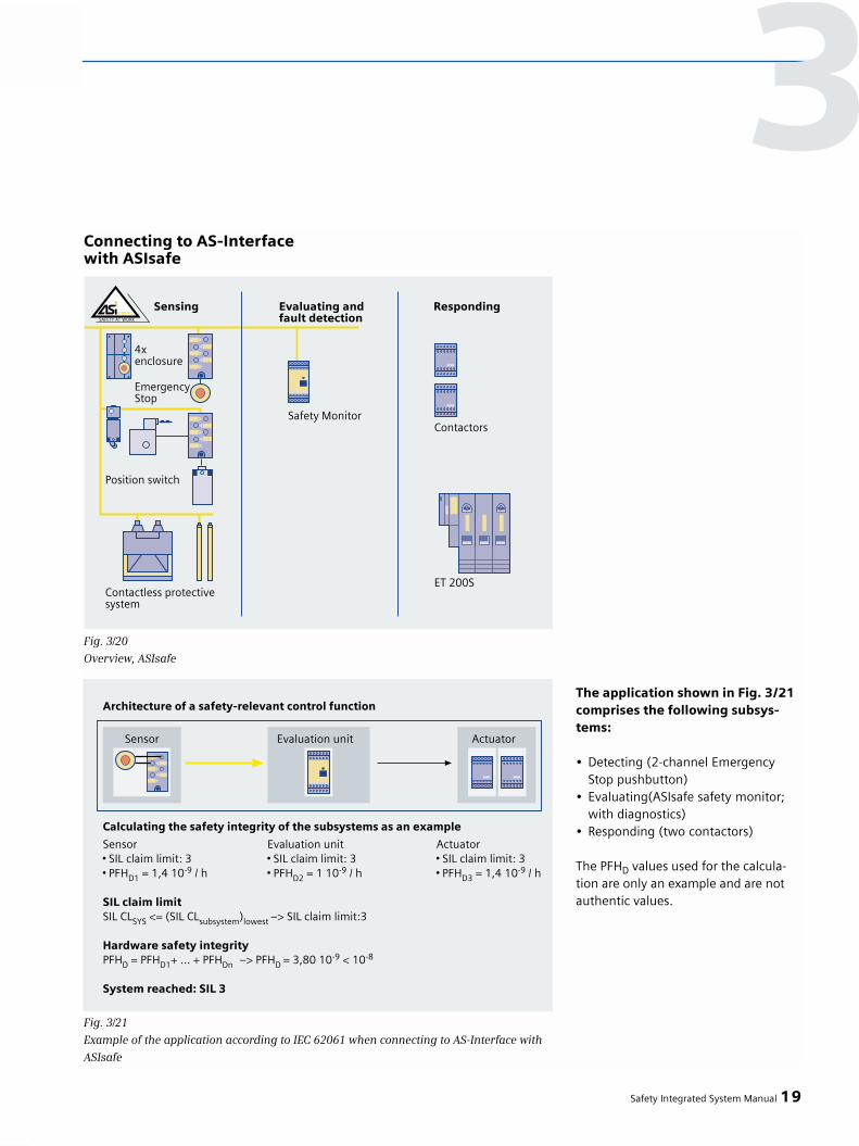
Connecting to AS-Interfacewith ASIsafe
The application shown in Fig. 3/21comprises the following subsys-tems:
• Detecting (2-channel Emergency Stop pushbutton)
• Evaluating(ASIsafe safety monitor; with diagnostics)
• Responding (two contactors)
The PFHD values used for the calcula-tion are only an example and are notauthentic values.
Safety Integrated System Manual 19
Fig. 3/20
Overview, ASIsafe
Fig. 3/21
Example of the application according to IEC 62061 when connecting to AS-Interface with
ASIsafe
3
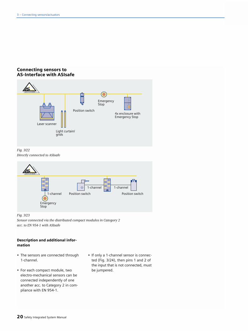
Connecting sensors toAS-Interface with ASIsafe
Description and additional infor-mation
• The sensors are connected through1-channel.
• For each compact module, twoelectro-mechanical sensors can beconnected independently of one another acc. to Category 2 in com-pliance with EN 954-1.
• If only a 1-channel sensor is connec-ted (Fig. 3/24), then pins 1 and 2 of the input that is not connected, must be jumpered.
20 Safety Integrated System Manual
3 – Connecting sensors/actuators
Fig. 3/22
Directly connected to ASIsafe
Fig. 3/23
Sensor connected via the distributed compact modules in Category 2
acc. to EN 954-1 with ASIsafe

Description and additional infor-mation
• Using a compact module, two protective doors can be monitored in Category 2 acc. to EN 954-1.The evaluation in this case is realized independently.
Description and additional infor-mation
• The sensors are connected through1 channel with crosswise data com-parison or 2 channels.
• For each compact module, a 2-channel, electro-mechanical sensor can be connected acc. to Category 4 in compliance with EN 954-1.
• If input 2 is not used, then this must be closed using an M12 cap in order to guarantee the IP67 degree of pro-tection.
Safety Integrated System Manual 21
Fig. 3/24
Connecting an Emergency Stop pushbut-
ton, Category 2 acc. to EN 954-1 with
a safety compact module
Fig. 3/25
Connecting two protective door monito-
ring circuits, Category 2 acc. to EN 954-1
to a safety compact module
Fig. 3/26
Connecting a sensor via the distributed safety compact module, Category 4
acc. to EN 954-1 with ASIsafe
3

Description and additional infor-mation
• Using a compact module, a protectivedoor can be monitored acc. to Cate-gory 4 in compliance with EN 954-1.
22 Safety Integrated System Manual
3 – Connecting sensors/actuators
Fig. 3/27
Connecting an Emergency Stop push-
button, Category 4 acc. to EN 954-1
to a safety compact module
Fig. 3/28
Connecting a protective door monitoring,
Category 4 acc. to EN 954-1 to a safety
compact module
Fig. 3/29
Connecting an actuator, Category 4 acc. to
EN 954-1 with ASIsafe using as an exam-
ple a safety monitor with an enable circuit
Description and additional infor-mation
• The ASIsafe safety monitor evaluatesall safety slaves and the feedback circuit of contactors (K1, K2).
The detailed principle of operation isdescribed in Chapter 4.2.
Connecting an actuator tothe AS-Interface with ASIsafe

Description and additional infor-mation
• The sensor signals are monitoredusing external, safety-related eva-luation units, e.g. safety relays orASIsafe.
• The enable circuits of the external safety-related evaluation units are each connected to one of 6 safety-related segments; this means that the fail-safe motor starter(s) are shutdown in a safety-related fashion.
Safety Integrated System Manual 23
3
Fig. 3/30
ET 200S Motor Starter Solution Local “shut down using an external safety system”
in Category 4 acc. to EN 954-1
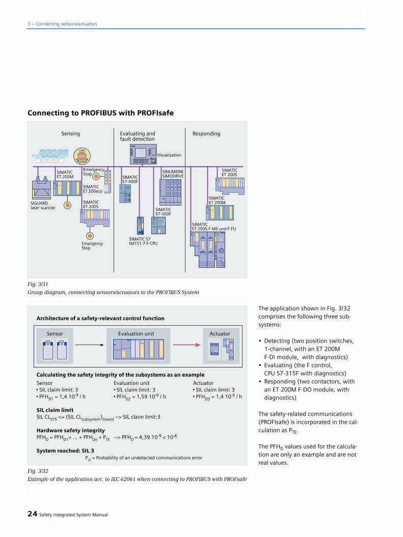
The application shown in Fig. 3/32comprises the following three sub-systems:
• Detecting (two position switches, 1-channel, with an ET 200M F-DI module, with diagnostics)
• Evaluating (the F control, CPU S7-315F with diagnostics)
• Responding (two contactors, with an ET 200M F-DO module, withdiagnostics)
The safety-related communications(PROFIsafe) is incorporated in the cal-culation as PTE.
The PFHD values used for the calcula-tion are only an example and are notreal values.
24 Safety Integrated System Manual
3 – Connecting sensors/actuators
Connecting to PROFIBUS with PROFIsafe
Fig. 3/31
Group diagram, connecting sensors/actuators to the PROFIBUS System
Fig. 3/32
Example of the application acc. to IEC 62061 when connecting to PROFIBUS with PROFsafe

Directly connecting sensorsto PROFIBUS with PROFIsafe
Description and additional infor-mation
• For the direct sensor connectionshown here, there is no additionalwiring required. Every device (slave) is assigned a bus address.
Safety Integrated System Manual 25
Fig. 3/33
Directly connecting sensors to PROFIBUS
Connecting a sensor to fail-safeSIMATIC input modules
Fig. 3/34
Connecting safety-related sensors. Typical connection SM326 24DI / ET 200M
3
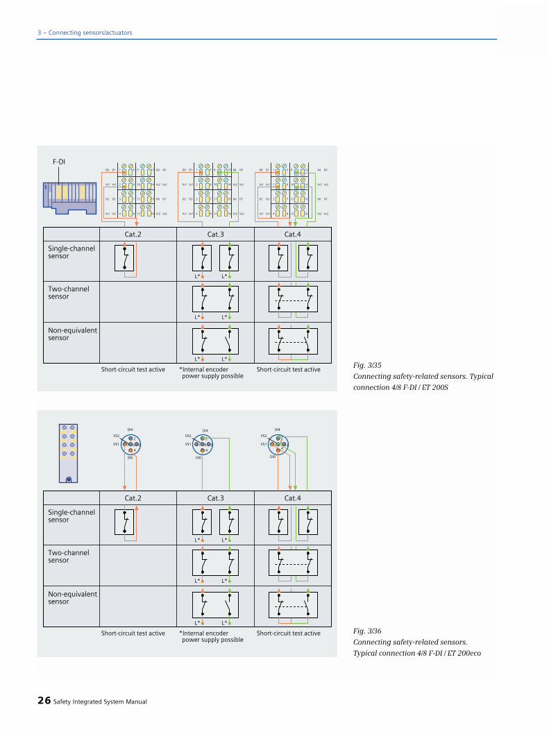
26 Safety Integrated System Manual
3 – Connecting sensors/actuators
Fig. 3/35
Connecting safety-related sensors. Typical
connection 4/8 F-DI / ET 200S
Fig. 3/36
Connecting safety-related sensors.
Typical connection 4/8 F-DI / ET 200eco

Description and additional infor-mation
• In this case, the safety F input module is used to implement the fault monitoring function.
• When the acknowledge button ispressed, this may not result in the plant or system restarting.
Description and additional infor-mation
The special feature associated with anapplication with a protective door is thecoupling with additional process sig-nals via the “safe programmable logic”.Generally, the release must be safelyprevented until all of the process para-meters are in a safe condition. Forexample, it is only permissible that theprotective door is opened, if
• A spindle that is running down hasreached a non-hazardous speed orhas come to a complete standstill.
• A vertical axis after the brake test with a defective brake has been moved into a safe position (stop position clamped position).
• Units with hazardous energy levelshave been brought into a safe condi-tion, e.g. laser or hydraulic systems.
Safety Integrated System Manual 27
Fig. 3/37
Connecting sensors through fail-safe
inputs of the ET 200M F I/O – using as an
example, Emergency Stop, protective door
monitoring and acknowledgment in
Category 2 acc. to EN 954-1
3
Fig. 3/38
Connecting sensors via fail-safe inputs of the ET 200S F I/O – an example of protective
door monitoring with tumbler mechanism in Category 3 acc. to EN 954-1

For category 3 according to EN 954-1, when using an individual positionswitch, it must be excluded that theactuator breaks. If it cannot be comple-tely excluded that the actuator cannotbe broken, then a second positionswitch must be additionally used (alsorefer to Fig. 3/42).
Non-safety relevant control of thesolenoids
of the tumbler mechanism in a non-safety relevant fashion is possible up to Category 3 acc. to EN 954-1.
Safety-related control of the sole-noids
of the tumbler mechanism in a safety-related fashion from Category 4 acc. to EN 954-1.
The objective of a tumbler mechanismis to maintain the isolating protectivedevice (e.g. guard) in the closed posi-tion. Further, the protective device isconnected to the machine control sothat the machine cannot start if theprotective device is not closed and isinterlocked. The isolating protectivedevice (e.g. guard) is kept interlockeduntil there is no longer any danger ofinjury.
Comment:
Up to Category 3 according to EN 954-1,the tumbler mechanism does not haveto be controlled in a safety-related fa-shion; however, for Category 4 acc. toEN 954-1, this must always be done ina safety-related fashion. The positionmonitoring of the interlocking device(solenoid) must, from Category 3 ac-cording to EN 954-1 onwards, be reali-zed individually, and may not be con-nected in series with the monitoringfunction of the separate actuator (dueto the poor fault detection level).
Description and additional infor-mation
• The contactless protective door moni-toring comprises a coded solenoid anda switching element (reed contacts).
• For Category 4, the internal voltage of the fail-safe modules must be used as power supply. The sensors are evaluated through two channels - in this case, the short-circuit test in the module must be activated.
• Non-equivalent magnetically operatedswitches can be connected to the fail-safe inputs of the SIMATIC S7 300F/400F.
• Up to Category 4, acc. to EN954-1, it is also possible to connect magnetically operated switches to ASIsafe or to a 3TK284x.
28 Safety Integrated System Manual
3 – Connecting sensors/actuators
Fig. 3/39
Connecting sensors via fail-safe inputs of the ET 200M F I/O – using as an example
fail-safe protective door monitoring with magnetically operated switches in Category 4
acc. to EN 954-1

Description and additional infor-mation
• Instead of a light curtain, light grid or the light barrier, a laser scanner can also be directly connected (laser scanners, due to their operating principle, are permitted up to Category 3 acc. to EN 954-1).
• On the fail-safe module, the evaluation must be realized through2 channels. The necessary test forshort-circuit and cross-circuit faultsis implemented by the contactlesselectro-sensitive protective equipment.This means that this test must be disabled in the associated module.
• Supplementary functions such asrestart and contactor monitoring - but also cyclic operation or mutingcan be implemented using the 3RG7847.. evaluation units or, as shown here, using a safety-related controller e.g. SIMATIC S7-300F/400F.
Safety Integrated System Manual 29
Fig. 3/40
Connecting sensors via fail-safe inputs of the ET 200S F I/O –
using as an example a contactless protective device type 3 and 4
acc. to IEC 61496-1, 2 or EN 61496-1, 2
3

Description and additional infor-mation
• The Emergency Stop acknowledgebutton is connected through asingle channel to a standard moduleand is evaluated in the safety-relatedprogram using a signal edge.
Description and additional infor-mation
• The connection for Category 4 acc. to EN 954-1 differs to that ofCategory 3 (Fig. 3/38) as a resultof the second position switch and the safety-related connection of the solenoids.
• Up to Category 4 acc. to EN 954-1 it is also possible to connect a door tumbler mechanism to ASIsafe or to 3TK284x safety relays.
30 Safety Integrated System Manual
3 – Connecting sensors/actuators
Fig. 3/41
Connecting sensors via fail-safe inputs of the ET 200M F I/O – using as an example
Emergency Stop, agreement button and acknowledgment in Category 4 acc. to EN 954-1
Fig. 3/42
Connecting sensors via fail-safe inputs of the ET 200S F I/O – using as an example
protective door monitoring with tumbler mechanism in Category 4 acc. to EN 954-1
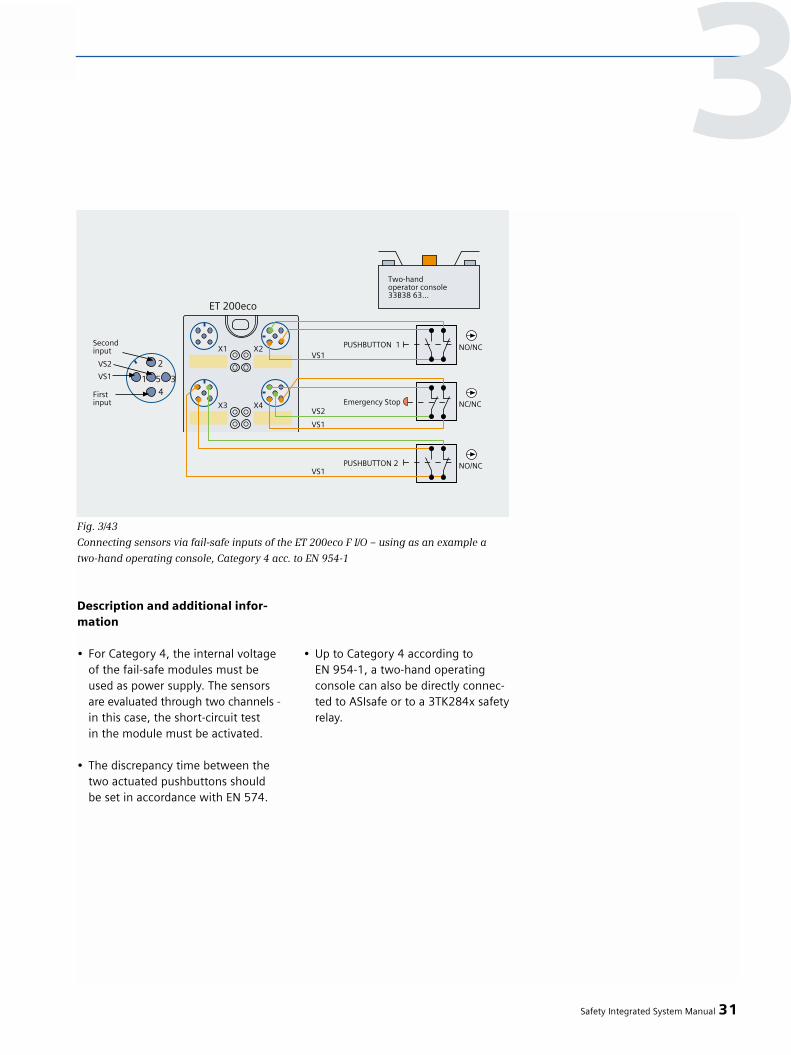
Description and additional infor-mation
• For Category 4, the internal voltageof the fail-safe modules must beused as power supply. The sensors are evaluated through two channels - in this case, the short-circuit testin the module must be activated.
• The discrepancy time between thetwo actuated pushbuttons shouldbe set in accordance with EN 574.
• Up to Category 4 according toEN 954-1, a two-hand operatingconsole can also be directly connec-ted to ASIsafe or to a 3TK284x safetyrelay.
Safety Integrated System Manual 31
Fig. 3/43
Connecting sensors via fail-safe inputs of the ET 200eco F I/O – using as an example a
two-hand operating console, Category 4 acc. to EN 954-1
3

Feedback signal from the load circuit
• The feedback signal from the loadcircuit should be derived as directlyas possible from the associated pro-cess quantity. This is realized, e.g. forcontactors, by feeding back a positi-vely-driven opening contact. The feedback does not have to be safety-related!
• However, it is preferable to have a direct feedback signal of the hydrau-lic pressure using a pressure sensor or a feedback signal from the movedmechanical system (endstop) via a Bero rather than using an indirect feedback signal from the hydraulic valve.
• The F-DO monitors the controlcables of the actuator - if a faultoccurs, the outputs are switched into a safe condition.
32 Safety Integrated System Manual
3 – Connecting sensors/actuators
Connecting actuators to PROFIBUS with PROFIsafe
Fig. 3/44
Connecting safety-related actuators, plus-minus /plus-plus switching
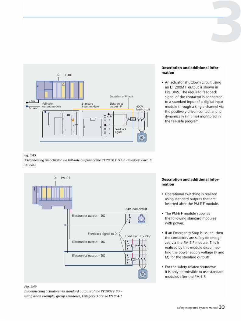
Description and additional infor-mation
• An actuator shutdown circuit using an ET 200M F output is shown in Fig. 3/45. The required feedback signal of the contactor is connected to a standard input of a digital input module through a single channel via the positively-driven contact and is dynamically (in time) monitored in the fail-safe program.
Description and additional infor-mation
• Operational switching is realizedusing standard outputs that are inserted after the PM-E F module.
• The PM-E F module suppliesthe following standard moduleswith power.
• If an Emergency Stop is issued, thenthe contactors are safely de-energi-zed via the PM-E F module. This isrealized by this module disconnec-ting the power supply voltage (P andM) for the standard outputs.
• For the safety-related shutdown it is only permissible to use standard modules after the PM-E F.
Safety Integrated System Manual 33
Fig. 3/46
Disconnecting actuators via standard outputs of the ET 200S F I/O –
using as an example, group shutdown, Category 3 acc. to EN 954-1
3
Fig. 3/45
Disconnecting an actuator via fail-safe outputs of the ET 200M F I/O in Category 2 acc. to
EN 954-1

Description and additional infor-mation
• Safe standstill:The safe standstill function (SH) prevents a connected motor from unexpectedly starting from standstill.Safe standstill should only be acti-vated after the drive has come to a standstill, as otherwise it loses its capability of braking.
• The drive is braked as quickly as possible via an input of the frequen-cy converter (STOP). Safe standstill isactivated after the drive comes to acomplete standstill, or, at the latestafter a defined maximum monitoringtime.
• The positively-driven feedback signalcontacts of the relay integrated in thefrequency converter, must be evalua-ted in the F control so that if the relay functions incorrectly, (e.g. the contacts weld), then this is detected and the higher-level line contactor is de-energized.
• STOP and safe standstill are addres-sed via a standard output module after the PM-E-F. In the fail-safe program section,the power rail of the PM-E-F is shut down as soon as the safe standstillfunction was activated (also refer to Fig. 3/19).
34 Safety Integrated System Manual
3 – Connecting sensors/actuators
Fig. 3/47
Shutting down an actuator via standard outputs of the ET 200S F I/O – using as an example
SIMOVERT MASTERDRIVES stop Category 1, acc. to EN 60204-1, in Category 3 acc. to
EN 954-1; safe standstill function with controlled drive stopping
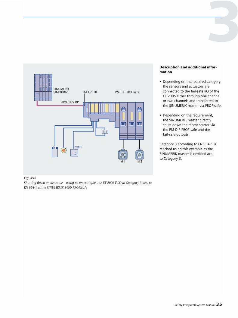
Description and additional infor-mation
• Depending on the required category, the sensors and actuators are connected to the fail-safe I/O of the ET 200S either through one channel or two channels and transferred to the SINUMERIK master via PROFIsafe.
• Depending on the requirement, the SINUMERIK master directlyshuts down the motor starter via the PM-D F PROFIsafe and the fail-safe outputs.
Category 3 according to EN 954-1 isreached using this example as theSINUMERIK master is certified acc. to Category 3.
Safety Integrated System Manual 35
Fig. 3/48
Shutting down an actuator – using as an example, the ET 200S F I/O in Category 3 acc. to
EN 954-1 at the SINUMERIK 840D PROFIsafe
3

Description and additional infor-mation
• The example in Fig. 3/49 showsan actuator shut down using onlyone ET 200S F output.
• The required feedback signal ofthe contactors is connected to thestandard input of a digital input module through a single channel via the positively-driven contacts and dynamically (in time) monitored in the fail-safe program.
Versions
• An ET 200S PROFIsafe motor starter replaces the discrete circuit through two load contactors (refer to Fig. 3/50).
36 Safety Integrated System Manual
3 – Connecting sensors/actuators
Fig. 3/49
Shutting down an actuator via fail-safe outputs of the ET 200S F I/O – using as an example
shutting down an actuator, Category 4 acc. to EN 954-1
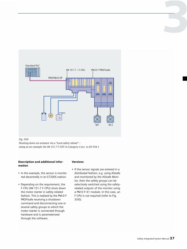
Description and additional infor-mation
• In the example, the sensor is monito-red decentrally in an ET200S station.
• Depending on the requirement, the F-CPU (IM 151-7 F-CPU) shuts downthe motor starter in safety-related fashion. This is realized by the PM-D FPROFIsafe receiving a shutdown command and disconnecting one or several safety groups to which the motor starter is connected through hardware and is parameterized through the software.
Versions
• If the sensor signals are entered in a distributed fashion, e.g. using ASIsafeand monitored by the ASIsafe Moni-tor, then the safety groups can be selectively switched using the safety-related outputs of the monitor using a PM-D F-X1 module. In this case, anF-CPU is not required (refer to Fig. 3/30).
Safety Integrated System Manual 37
Fig. 3/50
Shutting down an actuator via a “local safety island” –
using as an example the IM 151-7 F-CPU in Category 4 acc. to EN 954-1
3


Fail-safe communications usingstandard fieldbuses with PROFIsafeand ASIsafe
Selecting the correct installation tech-nology is an important step in reducingcosts. In standard technology, the moveto distributed concepts and the use ofmodern fieldbuses have already resul-ted in significant cost savings. In thefuture, further cost savings will beachieved by transferring additionalsafety-related signals along existingstandard fieldbuses.
Overall system with integratedsafety
By placing safety-related communica-tions on these proven standard field-buses, plant and system engineers canwork more cost-effectively in the stan-dard automation environment as wellas in safety technology. This is becausethey can use the same engineeringtools and methods. Contrary to con-cepts which use special buses to trans-fer safety-related data, in this case,there is data transparency between the standard and safety-related part of an overall plant or system withoutany additional interfaces.
PROFIsafe and PROFIBUS stationsco-exist on the same cable
The main stipulation when defining the PROFIsafe profile was that safety-related and standard communications
2 Safety Integrated System Manual
4 Fail-safe communicationsusing standard fieldbuses
Fig. 4/1
The basic principle of “Safety Integrated”:
A unified automation system with integrated safety functions
4.1 PROFIsafe
Fig.4/2
PROFIsafe and PROFIBUS nodes co-exist on the same cable
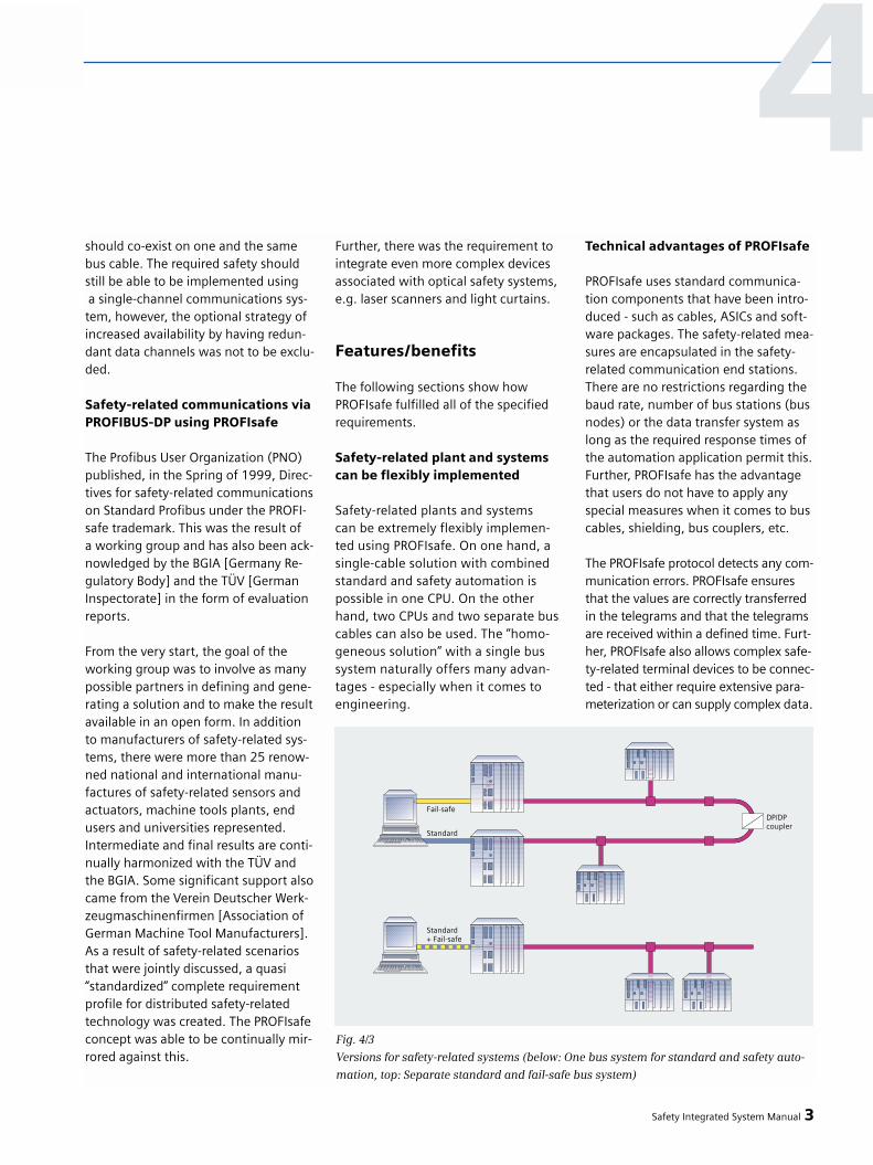
should co-exist on one and the samebus cable. The required safety shouldstill be able to be implemented usinga single-channel communications sys-tem, however, the optional strategy ofincreased availability by having redun-dant data channels was not to be exclu-ded.
Safety-related communications viaPROFIBUS-DP using PROFIsafe
The Profibus User Organization (PNO)published, in the Spring of 1999, Direc-tives for safety-related communicationson Standard Profibus under the PROFI-safe trademark. This was the result of a working group and has also been ack-nowledged by the BGIA [Germany Re-gulatory Body] and the TÜV [GermanInspectorate] in the form of evaluationreports.
From the very start, the goal of theworking group was to involve as manypossible partners in defining and gene-rating a solution and to make the resultavailable in an open form. In additionto manufacturers of safety-related sys-tems, there were more than 25 renow-ned national and international manu-factures of safety-related sensors andactuators, machine tools plants, endusers and universities represented.Intermediate and final results are conti-nually harmonized with the TÜV andthe BGIA. Some significant support alsocame from the Verein Deutscher Werk-zeugmaschinenfirmen [Association ofGerman Machine Tool Manufacturers].As a result of safety-related scenariosthat were jointly discussed, a quasi“standardized” complete requirementprofile for distributed safety-relatedtechnology was created. The PROFIsafeconcept was able to be continually mir-rored against this.
Further, there was the requirement tointegrate even more complex devicesassociated with optical safety systems,e.g. laser scanners and light curtains.
Features/benefits
The following sections show howPROFIsafe fulfilled all of the specifiedrequirements.
Safety-related plant and systemscan be flexibly implemented
Safety-related plants and systems can be extremely flexibly implemen-ted using PROFIsafe. On one hand, asingle-cable solution with combinedstandard and safety automation ispossible in one CPU. On the otherhand, two CPUs and two separate buscables can also be used. The “homo-geneous solution” with a single bussystem naturally offers many advan-tages - especially when it comes toengineering.
Technical advantages of PROFIsafe
PROFIsafe uses standard communica-tion components that have been intro-duced - such as cables, ASICs and soft-ware packages. The safety-related mea-sures are encapsulated in the safety-related communication end stations.There are no restrictions regarding thebaud rate, number of bus stations (busnodes) or the data transfer system aslong as the required response times ofthe automation application permit this.Further, PROFIsafe has the advantagethat users do not have to apply anyspecial measures when it comes to buscables, shielding, bus couplers, etc.
The PROFIsafe protocol detects any com-munication errors. PROFIsafe ensuresthat the values are correctly transferredin the telegrams and that the telegramsare received within a defined time. Furt-her, PROFIsafe also allows complex safe-ty-related terminal devices to be connec-ted - that either require extensive para-meterization or can supply complex data.
Safety Integrated System Manual 3
Fig. 4/3
Versions for safety-related systems (below: One bus system for standard and safety auto-
mation, top: Separate standard and fail-safe bus system)
4
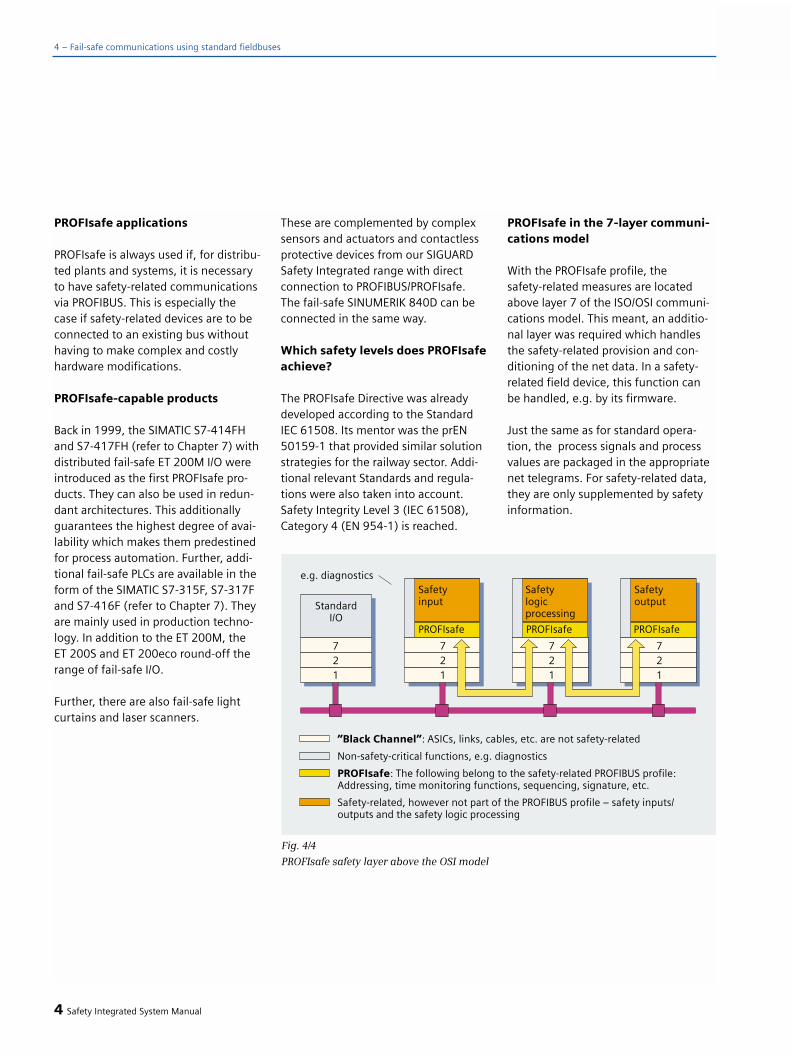
PROFIsafe applications
PROFIsafe is always used if, for distribu-ted plants and systems, it is necessaryto have safety-related communicationsvia PROFIBUS. This is especially thecase if safety-related devices are to beconnected to an existing bus withouthaving to make complex and costlyhardware modifications.
PROFIsafe-capable products
Back in 1999, the SIMATIC S7-414FHand S7-417FH (refer to Chapter 7) withdistributed fail-safe ET 200M I/O wereintroduced as the first PROFIsafe pro-ducts. They can also be used in redun-dant architectures. This additionallyguarantees the highest degree of avai-lability which makes them predestinedfor process automation. Further, addi-tional fail-safe PLCs are available in theform of the SIMATIC S7-315F, S7-317Fand S7-416F (refer to Chapter 7). Theyare mainly used in production techno-logy. In addition to the ET 200M, the ET 200S and ET 200eco round-off therange of fail-safe I/O.
Further, there are also fail-safe lightcurtains and laser scanners.
These are complemented by complexsensors and actuators and contactlessprotective devices from our SIGUARDSafety Integrated range with directconnection to PROFIBUS/PROFIsafe. The fail-safe SINUMERIK 840D can be connected in the same way.
Which safety levels does PROFIsafeachieve?
The PROFIsafe Directive was alreadydeveloped according to the StandardIEC 61508. Its mentor was the prEN50159-1 that provided similar solutionstrategies for the railway sector. Addi-tional relevant Standards and regula-tions were also taken into account.Safety Integrity Level 3 (IEC 61508),Category 4 (EN 954-1) is reached.
PROFIsafe in the 7-layer communi-cations model
With the PROFIsafe profile, thesafety-related measures are locatedabove layer 7 of the ISO/OSI communi-cations model. This meant, an additio-nal layer was required which handlesthe safety-related provision and con-ditioning of the net data. In a safety-related field device, this function canbe handled, e.g. by its firmware.
Just the same as for standard opera-tion, the process signals and processvalues are packaged in the appropriatenet telegrams. For safety-related data,they are only supplemented by safetyinformation.
4 Safety Integrated System Manual
4 – Fail-safe communications using standard fieldbuses
Fig. 4/4
PROFIsafe safety layer above the OSI model
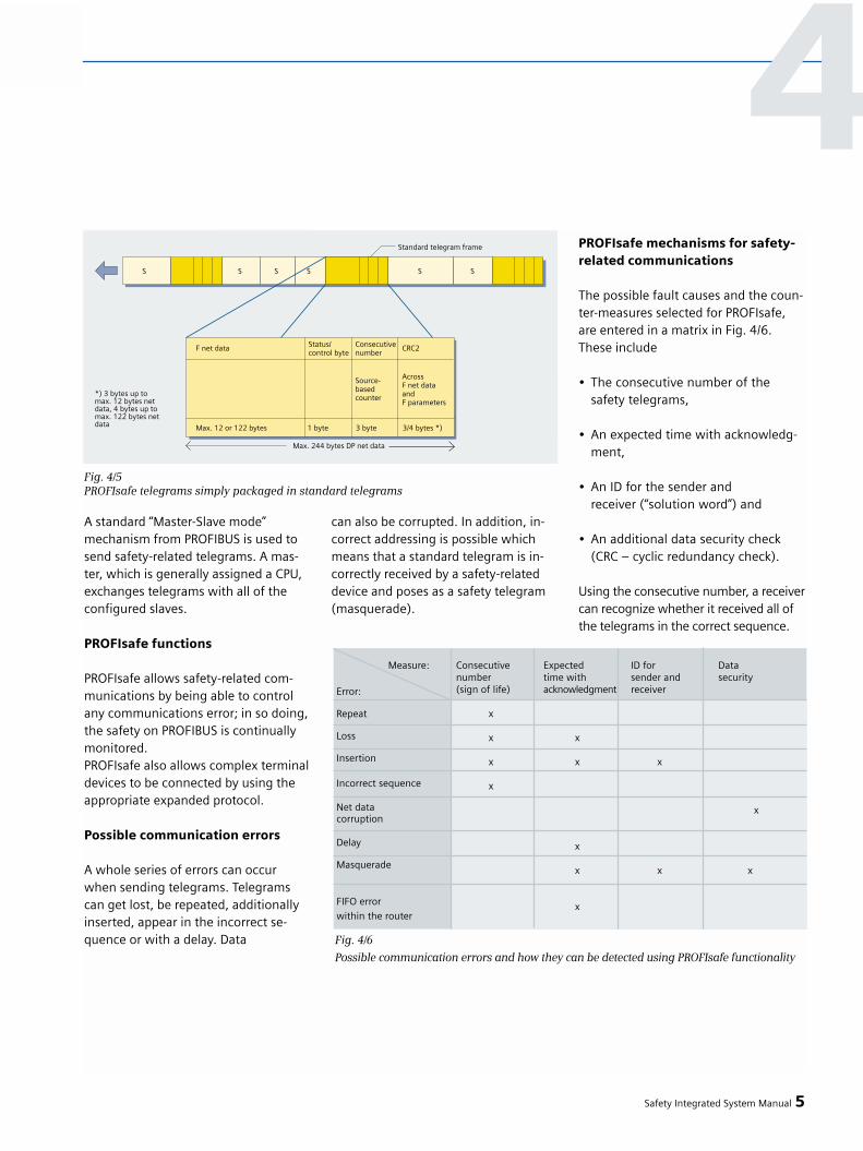
A standard “Master-Slave mode” mechanism from PROFIBUS is used tosend safety-related telegrams. A mas-ter, which is generally assigned a CPU,exchanges telegrams with all of theconfigured slaves.
PROFIsafe functions
PROFIsafe allows safety-related com-munications by being able to controlany communications error; in so doing,the safety on PROFIBUS is continuallymonitored. PROFIsafe also allows complex terminaldevices to be connected by using theappropriate expanded protocol.
Possible communication errors
A whole series of errors can occurwhen sending telegrams. Telegramscan get lost, be repeated, additionallyinserted, appear in the incorrect se-quence or with a delay. Data
can also be corrupted. In addition, in-correct addressing is possible whichmeans that a standard telegram is in-correctly received by a safety-relateddevice and poses as a safety telegram(masquerade).
PROFIsafe mechanisms for safety-related communications
The possible fault causes and the coun-ter-measures selected for PROFIsafe,are entered in a matrix in Fig. 4/6.These include
• The consecutive number of thesafety telegrams,
• An expected time with acknowledg-ment,
• An ID for the sender andreceiver (“solution word”) and
• An additional data security check(CRC – cyclic redundancy check).
Using the consecutive number, a receivercan recognize whether it received all ofthe telegrams in the correct sequence.
Safety Integrated System Manual 5
4
Fig. 4/5PROFIsafe telegrams simply packaged in standard telegrams
Measure: Consecutive Expected ID for Datanumber time with sender and security(sign of life) acknowledgment receiver
x
x x
x x x
x
x
x
x x x
x
Error:
Repeat
Loss
Insertion
Incorrect sequence
Net datacorruption
Delay
Masquerade
FIFO error
within the router
Fig. 4/6
Possible communication errors and how they can be detected using PROFIsafe functionality

In safety-related systems, it isn'tenough that a telegram transfers thecorrect process signals or values, butthese must also be received within adefined time (fault tolerance time), sothat the particular device can automati-cally and locally initiate the safety-rela-ted response when necessary. To reali-ze this, the stations have an adjustabletime-out function, which is restartedafter a safety-related telegram hasbeen received.
The 1:1 relationship between a masterand slave makes it easier to recognizeincorrectly routed telegrams. Both ofthese have a unique ID in the network(“solution word”), which can be used to check the authenticity of a telegram.Data integrity using CRC plays a keyrole. In addition to the data integrity of the transported net data, CRC is alsoresponsible for the integrity of the pa-rameters in various terminal devices.
The data integrity measures and thereliability of the standard PROFIBUSwere not used for the proof of safety.This meant that the proof of safety forPROFIsafe was somewhat more timeconsuming and complex, but has theadvantage that users do not have toapply any special measures regardingbus cables, shielding, bus couplers, etc.for PROFIsafe.
SIL monitor for safety monitoringon PROFIBUS
A Markov model is specified in prEN50159-1. In a slightly expanded form,this can be used to calculate the residu-al error probability of safety circuits. It assumes three essential causes ofcorrupted messages which must all be detected by the two data integritydevices: Failures in ASICs and drivers,electromagnetic disturbances and aspecial case where only the safety devi-ces in the bus ASIC have failed. Withoutspecific measures, special proof wouldhave to have been provided for everybus configuration.
This would represent a significant res-triction for an open standard fieldbussuch as PROFIBUS.
Thus, a mechanism was created thatguarantees that the SIL levels are main-tained over the lifetime of a distribu-ted, safety-related automation solution- and that independent of the compo-nents used and the configuration: Apatented SIL monitor. This is implemen-ted in the software. This monitor takesinto account all of the conceivable con-sequences arising from errors/faults,and initiates a response if the numberof faults or disturbances exceeds a spe-cific level per unit time. The number ofpermissible faults/errors per unit timedepends on the selected SIL stage.
6 Safety Integrated System Manual
4 – Fail-safe communications using standard fieldbuses
Fig. 4/7
Patented SIL monitor continually monitors the functional safety of PROFIsafe

Connecting complex terminal devices to PROFIsafe
As a result of the various discussions,the working group members quicklysaw that a pure profile descriptionwould not be adequate for fast imple-mentation in many “PROFIsafe pro-ducts”. Especially optical safety-relatedtechnologies, e.g. utilizing laser scan-ners and light curtains require a highnumber of parameters which demandspecial handling in the teach-in phase.The working group described solutionsin the Guidelines, which could be app-lied for these and additional complexdevices. PROFIsafe components can beparameterized and diagnosed using aPC directly connected to PROFIBUS – as is usual for PROFIBUS.
In order to make it simpler to engineersafety-related circuits, the engineeringtools have access to all of the necessaryparameters. When calculating the ove-rall response times of the safety pro-cess, manufacturers must specify theprocessing times of sensors and actua-tors in the GSD (master device data)data sheets.
PROFIsafe interacting with TIA
This means that PROFIsafe provides ahigh degree of integration and standar-dization for safety technology, similarto the standard automation solutionson PROFIBUS. This is completely in linewith the philosophy of “Totally Integra-ted Automation” (TIA), and creates sig-nificant flexibility when solving evenmore complex tasks.
The AS-Interface system
Overview
The AS-Interface Safety concept (in thefollowing abbreviated as “ASIsafe”) al-lows safety-related components to bedirectly integrated into an AS-Interfacenetwork for fail-safe protection of man,machine and the environment. Thesesafety-related components includeEmergency Stop command devices,protective door switches and safetylight grids.
Using ASIsafe, it is possible to shutdown in safety-related fashion up toCategory 4 (EN 954-1) or SIL3 (IEC 61508). Thiscan be done but still keeping the ad-vantages of simple wiring at a favora-ble cost.
The following advantages are obtainedfor machines and plant builders as a re-sult of ASIsafe:
• Safety-related components can be simply integrated into the standard automation
• Favorably-priced design as neither fail-safe PLC nor a special master are required
• Safety systems can be more quickly configured using AS interface thanksto the flexible wiring
• Integrated diagnostics using AS interface increases the-service-friendliness of the system and allowsfast troubleshooting. This significant-ly reduces downtimes.
Safety Integrated System Manual 7
4
Fig. 4/8
Parameterizing and troubleshooting PROFIsafe components
4.2 ASIsafe

4 – Fail-safe communications using standard fieldbuses
This means that simple engineeringand commissioning of AS-Interface alsopermits this to be achieved for safety-related technology.
Customer benefits
• Safety-related systems can be quicklyconfigured thanks to the extremely flexible topology and simple connec-tion system of AS-Interface.
• Minimum service times and downtimes thanks to the integrated dia-gnostics.
• Especially favorably-priced systems are possible without fail-safe PLC andwithout special master.
• Safety and non-safety data on one bus allow seamless, integrated auto-mation solutions.
• The AS-Interface can be very easily configured with just a push of the knob on the master.
• Highest degree of safety: Certified up to Category 4 acc.to EN 954-1 and SIL3 acc. to IEC 61508.
• Safety systems can be simply engineered using straightforward, graphic software (“asimon”).
• Existing systems can be simply expanded.
• Certified by the German Technical Inspectorate and UL
Advantages
Advantages with respect to conventio-nal safety technology:
• Shorter downtimes thanks to the integrated diagnostics.
• Higher flexibility by programminginstead of hard-wiring the safety-related logic.
• Mounting and installation are signifi-cantly simpler, as, for example, no complicated feedback wiring is required for distributed shutdown operations.
• A solution can be simply duplicated on several machines/plants by copy-ing the safety program.
• The safety logic can be simply modi-fied by making the appropriateprogram changes.
• Only one interface to the HMI system - therefore seamless diagnostics.
• Reduced design and configurationtimes and costs thanks to the inte-grated diagnostics: The status of the safety system does not have to be signaled to the control using special I/O modules.
• Lower number of spare parts asthe safety logic, programmed asuser software, replaces thewidest range of hardware.
• Fast overview of the safety functionality of the plant/system using a straightforward, graphic tool.This eliminates complex switchinganalyses when plants and systems are expanded.
• If, as a result of acceptance tests by the Germany Technical Inspectorate, additional safety measures are requi-red, the flexibly wiring and configu-ring makes it simple to integrate additional safety-relevant compo-nents.
Advantages over other safety fieldbuses:
• Neither a fail-safe PLC nora special master are required
• Simple, non-shielded 2-conductorcable simplifies installation andalso speeds it up
• The well-proven insulation displacement technique eliminatesthe time-consuming procedureof stripping insulation and assembling bus cables
• Only one AS-Interface cablefor safety and non-safety relevantcommunications
• Therefore only one interface toHMI systems
• The program blocks do not haveto be additionally accepted by theGerman Technical Inspectorate.
• Extremely simple programmingusing graphic hardware-oriented tool (refer to Section 4).
• Hardware - such as EmergencyStop command devices, protective door switches and safety-relatedlight curtains - can be directly incorporated using the integrated AS-Interface slave
8 Safety Integrated System Manual

Highlights
• Lower engineering costs• Extremely straightforward and
fast commissioning• Lower costs as a fail-safe control
is not required• More efficient in operation
thanks to the integrated diagnostics• 40 ms response time
The following benefit from ASIsafe:• Machinery and plant builders
thanks to the cost savings, and• Plant operating companies thanks to
the higher plant availability andhigh degree of flexibility
Applications
ASIsafe has already been successfullyused in many applications spanning allindustry sectors.
For instance, the following applicationswere successfully secured using ASIsafe:
• Transport of goods on conveyor belts• Presses• Machining centers in the automobile
industry• Machine tools• Escalators• Paper machines• Packaging machines in the
food and beverage industry
Principle design and function
The basic design of an ASIsafe systemis shown in the following diagram
A conventional AS-i network comprisesa control/master, power supply unit,yellow AS-i cable and various slaves.Just two additional components arerequired for safety-related applications:A Safety Monitor and safety slaves.
A dynamic safety data transfer protocolforms the basis for secure data transfer.
In the factory, a code table is saved inevery safety slave. This means that thesafety monitor can uniquely identify it.Every safety slave must be parameteri-zed in the safety monitor by the useracknowledging the prompt “teach-insafety slave”. Its associated code tableis then saved in the comparator of thesafety monitor. Each time that the mas-ter calls, a check is made by the compa-rator as to whether the expected codevalues match the actual code values.
If deviations occur or monitoringtimes are violated (watchdog), safeshutdown is initiated at the SafetyMonitor through dual-channel enablecircuits.
The code value “0000" is reserved forspecific stopping. For example, if anEmergency Stop button is pressed,”0000" is sent to the safety monitor.This then initiates a safety-related shut-down via the appropriate enable circuit.
The safety monitor receives the safety-related code tables with the masterinterrogation, typical for the AS-Interfa-ce. The information is only sent to themaster PLC - but it does not have anactive role. For example, the informa-tion can be additionally evaluated fordiagnostic purposes using the plant orsystem control.
Safety Integrated System Manual 9
4
Fig. 4/9
Basic ASIsafe structure

Safety monitor functions
The AS-Interface safety monitor evalua-tes the safety-related inputs of the safe-ty slaves and the inputs from the feed-back circuit (refer to Fig. 4/10). Usinglogic blocks, it logically combines thisinformation. This is used to determinethe safety output of the enable circuitof a safety monitor.
In so doing, the safety monitor startsdifferently depending on the paramete-rized start blocks.
The AS-Interface safety monitor has a wide range of function blocks thatallow the widest range of system con-figurations.
Monitoring blocks:
The safety-related slaves can be para-meterized using the following monito-ring blocks:
In addition, all monitoring blocks canbe parameterized for starting tests andlocal acknowledgment.
10 Safety Integrated System Manual
4 – Fail-safe communications using standard fieldbuses
Fig. 4/10
Safety monitor functions
Table
Safety classes for the various configurations
Two-channel, positively-driven Two redundant contacts; Emergency Stop acc. to Category 3/4 must be simultaneously actuated (EN 954-1)
Two-channel dependent Two redundant contacts; Two-hand operations; Both must be opened/closed Protective doors withafter a synchronization time two safety switches
Two-channel dependent with Two redundant contacts; Slow-action switchesde-bounce Both must opened/closed Switch with high bounce times
after a de-bounce and synchronizing time
Two channel conditionally dependent Two redundant contacts; Door switch with interlockingOne contact is used for monitoring, the second contact is used forinterlocking and monitoring
Two-channel independent Two independent switching signals act Protective door monitoringon the inputs of a safety slave acc. to Category 2 (EN 954-1)
Standard slave Operational switching -Button Local acknowledgment of several blocks Common acknowledgment
of light gridsNOP (No Operation) Space retainer for a block The same, expanded diagnostics
to keep the block indices can be kept for different plant confi-gurations
Monitoring blocks Function Examples
Logic operation blocks:
The following functions can be selectedto logically combine the safety-relatedinputs:
• AND• OR• Flip-flop• Switch-in and switch-out
delay times up to 300 s• Pulses
Feedback circuit blocks:
These blocks allow the state of thedownstream motor contactor to be mo-nitored for dynamic checking (online).
Using these blocks, it is also possible toremotely reset the safety monitor whenfaults occur
Output blocks:
These blocks define how a safe stand-still should be implemented. The follo-wing can be set:• Stop Category 0 (immediate stop)• Stop Category 1 (delayed stop up to
300 s)• Door tumbler mechanisms with
and without standstill monitor (for two conditional enable circuitsof a monitor)
Starting blocks:
These blocks allow a plant or system tostart in a defined fashion.The following settings are possible:
Automatic restart• Monitored start with an acknow-
ledgment using a standard AS-i slave• Monitored start using a start
input at the safety monitor• Monitored start using an acknow-
ledgment signal from a safety-relatedAS-i slave
The safety system is simply and intuiti-vely parameterized: The blocks aredragged & dropped into the appropria-te enable circuit of the safety monitor.
By double-clicking on the appropriateblock, this can be further configuredusing a dialog window that is then dis-played.
Safety Integrated System Manual 11
4

ASIsafe is simply configured usingasimon
Every monitor can be simply configu-red with the PC using the asimon confi-guring software. The PC is connectedto the Safety Monitor using an appro-priate cable.
The safety logic is parameterized bydragging & dropping.
To do this, for each safety function, theappropriate graphic safety componentsare simply dragged from the cataloginto the enable circuit of the safety mo-nitor to be tripped (refer to Fig. 4/11).In so doing, the operating modes aswell as additional functions such asdoor tumbler mechanisms, stop Cate-gory 0 and 1, contactor monitoring,restart inhibit, local acknowledgmentand agreement button can be set.
AND and OR logic blocks are also avai-lable.
Connecting safety-related signalsbetween two AS-Interface net-works
Safety-related data can be exchangedbetween two ASIsafe networks.
To do this, an enable circuit of a safetymonitor from network 1 is connectedto a safety-related input at a modulefrom network 2.
12 Safety Integrated System Manual
4 – Fail-safe communications using standard fieldbuses
Fig. 4/11
asimon configuring software
Fig. 4/12
Exchanging safety data between two ASIsafe networks
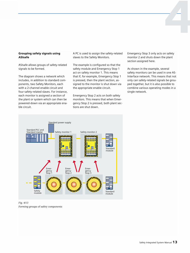
Grouping safety signals using ASIsafe
ASIsafe allows groups of safety-relatedsignals to be formed.
The diagram shows a network whichincludes, in addition to standard com-ponents, two Safety Monitors, eachwith a 2-channel enable circuit andfour safety-related slaves. For instance,each monitor is assigned a section ofthe plant or system which can then bepowered-down via an appropriate ena-ble circuit.
A PC is used to assign the safety-relatedslaves to the Safety Monitors.
The example is configured so that thesafety module and Emergency Stop 1act on safety monitor 1. This meansthat if, for example, Emergency Stop 1is pressed, then the plant section, as-signed to the monitor is shut down viathe appropriate enable circuit.
Emergency Stop 2 acts on both safetymonitors. This means that when Emer-gency Stop 2 is pressed, both plant sec-tions are shut down.
Emergency Stop 3 only acts on safetymonitor 2 and shuts down the plantsection assigned here.
As shown in the example, several safety monitors can be used in one AS-Interface network. This means that notonly can safety-related signals be grou-ped together, but it is also possible tocombine various operating modes in asingle network.
Safety Integrated System Manual 13
4
Fig. 4/13
Forming groups of safety components

Integrating into TIA
AS-Interface networks with ASIsafe
An ASIsafe network with Safety at Workcomponents can be subordinate to adistributed ET 200S I/O station. In thiscase, an enable circuit of a safety moni-tor is wired-into the safety circuit of the
Simple diagnostics
If a safety slave is initiated, then ittransfers “0000”.
This information is available at themaster and can be simply evaluated by the control.
ET 200 S. The response time of theET200S SIGUARD of 20 ms is added to the response time of ASIsafe (max.40 ms).
Detailed diagnostics
In addition to the pure asimon configu-ration software, Siemens also suppliesfunction blocks for the S7-200 and S7-300 on the ASIsafe CD-ROM. This al-lows detailed diagnostics to be carried-out for all of the parameterized blocks(refer to Fig. 4/15).
To do this, an AS-i address must be as-signed at the safety monitor using theconfiguration software. The evaluationis made using function blocks in thePLC.
14 Safety Integrated System Manual
4 – Fail-safe communications using standard fieldbuses
Fig. 4/14ASIsafe under ET 200S Motorstarter

Safety Integrated System Manual 15
Fig. 4/15Function block for detailed diagnostics of the ASIsafe network in the PLC
4

Overview
SIRIUS position switches are used to
• Detect the position of movingmachine parts and components
• Detect and sense hazardous motion of machine parts and components
• Monitor protective devices with jointssuch as swiveling doors, hatches, etc.
• Monitor protective devices that canbe laterally shifted - such as slidingdoors, protective meshes etc.
Features
SIRIUS position switches offer
• A comprehensive range of products with standardized enclosures and operating mechanisms/actuators
• Simple to mount solutions to detect and monitor hazardous motion and access areas.
• Standardized device mountingacc. to Standard EN 50041 and EN 50047
• Maximum protection against tam-pering and manipulation of the protective devices - e.g. using multi-ple coded, separate actuators
• Protective devices are monitoredup to Category 4 acc. to EN 954-1
• Integrated in the ASIsafe bus system
• High degree of protection, even for standard products
Applications
SIRIUS position switches are used, amongother things, for the following tasks:
• In the plant and machinery area to monitor protective barriers andaccess hatches on printing machines.
• Position switches with tumblermechanism are predominantly used to monitor parts of the machinewith increased potential hazard -such as robot cells. A protectivedoor is safely locked until themachine comes a standstill.
• A plant or system is safety shut downwhen it reaches the appropriate end stop, e.g. for elevators and escalators.
• Protective doors are monitored using magnetically-operated switches that are immune to manipulation when the switch is mounted so that it is covered - this also plays a significant role in areas requiring cleaning and disinfection.
2 Safety Integrated System Manual
5 Safety industrial controls
5.1 SIRIUS position swit-ches

Safety Integrated System Manual 3
5Thanks to the wide variety of actuators, enclosures and contact systems that are required in the field, SIRIUS 3SE position switches are convincing in almost every application.With positively opening contacts.Versions with dimensions, mounting points and characteristic values are available thatare in compliance with Standards EN 50041 to EN 50047.
As a result of their significantly lower switching distance and precise switching points, our short-stroke switches ensure safe shutdown even for extremely short actuation travel.
Standard position switches
A wide variety of enclosures and actuator versions is available to monitor protective doors.Thanks to the multiple mechanically coded actuator, it is not possible to simply bypass protective devices.With positively opening contacts.Tumbler mechanism:Position switches with separate actuator and tumbler mechanism keep a protective door interlocked until the operating zone can be entered without incurring any danger. An electricalsignal, e.g. from a standstill (zero speed) monitor controls the interlocking solenoids and therefore releases the protective door.
Interlocking with spring force (closed-circuit principle) as well as interlocking with solenoid force (open-circuit principle) versions with 4 contacts as standard are available.
Position switches with separate actuator/tumbler mechanism
Versions with a standard enclosure acc. to EN 50047 to be mechanically connected to thehinge axis as well as hinge-mounted switches with already mounted hinge are available.With positively opening contacts.The NC contacts already open at protective door opening angles of 4 degrees andissue the command to shut down. For versions with snap-action contacts, the signalingcommand (NO contact) is simultaneously issued with the shutdown command (NC contact).
Hinge-mounted switches
These contactless magnetically-operated switches offer a high degree of protectionagainst manipulation. They are available in 3 different designs.
The safety-related evaluation and monitoring to achieve Category 4 acc. to EN 954-1 is realized using the 3TK284, 3SE6 safety relays, ASIsafe and F-SIMATIC.
Magnetically-operated switches

Design
• Standard switches:Modular design with replaceable elements (actuator head, enclosure, contact blocks).
• Separate actuator as well as switcheswith tumbler mechanisms:Fixed contact unit can be combined with various actuators (standard actuators, with lateral mounting and radius actuators).
• Hinge-mounted switches:Compact contact unit that is directly mounted on the hinged axis or with already pre-assembled hinge.
• Standard connections for mechanicalposition switches:Metric glands, preferably M20x1.5. Versions with M12 connector and multi-pole connectors are available.
• Magnetically-operated switches:Compact, device cast in resin where the connecting cables are alreadyconnected.
Examples
1. Standard switches:
Sensing end positions and endstops ontool slides in special-purpose machin-ery construction
2. Switches with separate actuator:
Protective door monitoring for auto-matic production equipment
4 Safety Integrated System Manual
5 – Safety industrial controls

3. Hinge-mounted switches:
Monitor access hatches for wood-working machines
4. Magnetically-operated switches:
Possible combination of monitoring unit - magnetically-operated switch system
Safety Integrated System Manual 5
5
Monitoring unit Magnetically-operated Magnetically-operated
switch 1NC/1NO switch 2NC
contact contact contact contact
3SE6 605-1BA 3SE6 605-2BA 3SE6 605-3BA 3SE6 604-2BA
(M30) (25 x 33 mm) (25 x 88 mm) (25 x 88 mm)
Switching relay Switching relay Switching relay Switching relay
3SE6 704-1BA 3SE6 704-2BA 3SE6 704-3BA 3SE6 704-2BA
Relay output
SIRIUS safety relay,
6-fach 1) 3SE6 806-2CD00
Electronics output
SIRIUS safety relay,
electronic 2) 3TK284.
SIRIUS safety relay, with contactor relay,
electronic 2) 3TK285.
SIRIUS safety load feeders
electronic 2) 3RA7.
ASIsafe 2) 3RK1.
SIMATIC ET 200S 2)
PROFIsafe 2) 4/8F-DI DC24V
SIMATIC ET 200M 2) SM326, DI DC24V
SIMATIC S7 300F 2) SM326, DI 8 x Namur
Possible combination – monitoring unit – magnetically-operated switch
•
–
–
–
–
•
•
•
–
–
–
–
•
•
•
–
–
–
–
•
•
–
•
•
•
•
•
•
1) Category 3 acc. to EN 954 can be achieved2) Category 4 acc. to EN 954 can be achieved

6 Safety Integrated System Manual
5 – Safety industrial controls
Standard position switches • Positively opening contacts, acc. to IEC 947-5-1
• High contact reliability even at5V DC / 1mA
• Suitable for ambient temperaturesfrom -35° to +85°C
• Extremely high mechanical endurance(30 million switching operations)
• High IP67 degree of protection• Various NC/NO contact versions - up to
4 contacts are possible• Enclosure in compliance with EN 50041,
EN 50047 and special designsPosition switches with • Moulded plastic or metal enclosure in separate actuator/ IP66 and IP67tumbler mechanism • Enclosures acc. to EN 50047, EN 50041
and Special designs • Safety standard for protective door
interlocking functions acc. to EN 1088• Can be approached from 4 or 5
directions• High IP65 or IP67 degree of protection• Mechanical endurance 1x10⁶
operating cycles• Ambient temperature from –30o to +85oC• Various NC/NO contact versions, up to 4
contacts possible, as well as position monitoring of the actuator and the interlocking solenoids with up to 2 contacts.
Hinge-mounted switches • Enclosure acc. to EN 50047 for hinge mounting1NO/1NC snap-action, 5 degrees or 15 degrees switching point
• Switch with integrated hinge for 40 mm profile, switching point 4 degrees, 5 or 15 degrees, 1NO/2NC slow-action contacts
SIRIUS position switches
Technical data

Overview
The SIRIUS Emergency Stop commanddevices are used to manually shut downplants and systems when hazards occurand are initiated by operating person-nel (acc. to ISO 13850 (EN 418)).
Features
SIRIUS Emergency Stop command devicesdistinguish themselves as a result of:
• Extensive product range with variousEmergency Stop operator components- rotate to release- pull to release- key-operated release
• Can be simply and quickly mounted• Plastic and metal versions• Embedded - among other things in
the AS-Interface bus system
The following advantages are obtained:
• Can be used up to Category 4 acc. toEN 954-1 thanks to the positively-opening NC contacts
• High degree of protection up to IP67• Harmonized range of command
and signaling devices• Directly connected to ASIsafe, direct-
ly connected to the yellow profiled cable
Applications
In all types of plants and machines,Emergency Stop command devicesallow plants and systems to be manuallyshut down when hazards arise and areused in the following industry sectors:
• General machine construction• Automation technology• Special-purpose machine building• Woodworking industry• Machine tool construction• Food and beverage industry
Product family/productgroups
The family of SIRIUS command devicesincludes, in addition to Emergency Stopactuators:• Pushbuttons• Indicator lights• Selector switches• Key-operated switches• Emergency Stop command devices
These devices are available either inround or square moulded-plastic ver-sions as well as in round metal versions.
The Emergency Stop command devicescan be used up to Category 4 acc. toEN 954-1. They all have positively-opening contacts.
For safety-related evaluation and moni-toring, 3TK28, ASIsafe and F-SIMATICare used in order to achieve Category 4using a safety-related module.
Design
The command devices have a modulardesign and comprise actuator elementssuch as Emergency Stop, pushbuttonas well as a holder to retain the devicein the front panel hole and the contactelements and lamp sockets that can besnapped-in.
The actuator elements are mounted in a standard 22.5 mm front panel holeand are retained from the rear usingclips. Contact elements and lamp sock-ets are snapped onto the rear of theactuator element.
Contact elements and lamp sockets areavailable with either screw terminal,Cage Clamp terminal as well as solderpins that allow them to be solderedonto PC boards.
Example
Automated production line with Emer-gency Stop command devices locatedat exposed positions. These are used tomanually shut down the line or modulewhen a hazard occurs.
Safety Integrated System Manual 7
5.2 SIRIUS EmergencyStop
5
Degree of protection IP66 (plastic versions)IP67 (metal versions)
Mounting hole 22.3 mm+0.4 mm (round designs, plastic and metal)26 x 26 mm (square plastic versions)
Rated operating voltage 400 V, AC 12Rated operating current 10 V, AC 12Contact reliability 5 V, 1 mA(test voltage, current)
SIRIUS Emergency Stop
Technical data

5 – Safety industrial controls
Overview
SIRIUS command devices are used tomanually shut down plants when haz-ards occur and this is initiated by oper-ator personnel. Classic Emergency Stopcommand devices (acc. to ISO 13850(EN 418)) are available for this pur-pose.
SIRIUS signaling devices are used tovisually and acoustically signal machineand plant states. Signaling devices areavailable for the modular range of“SIRIUS 3SB3 command and signalingdevices” as well as the 8WD signalingcolumns with a comprehensive rangeof accessories.
Features
SIRIUS command devices include:
3SB3 Emergency Stop pushbuttons
• Extensive product range with variousEmergency Stop operator components- release by turning, pulling and key-release
• Emergency Stop function acc. to ISO 13850 (EN 418)
• Fast and simple to install• Moulded plastic and metal versions• One-man installation without any
special tools• Actuator elements can be equipped
in a modular fashion• Extensive range of accessories• Embedded, among other things, in
the AS-Interface bus system
3SB3 two-hand operator consoles
• Solution in compliance with the Stan-dards acc.to EN 574 and DIN 24980
• Emergency Stop function acc. to ISO 13850 (EN 418)
• Moulded plastic and metal versions• Rugged metal versions for the tough-
est of application conditions• AS-Interface solution that can be
retrofitted
3SE7 cable-operated switches
• Emergency Stop function acc. to ISO 13850 (EN 418)
• Versions for cable lengths up to 100 m• LED signal display with high intensity• Monitoring function for cable break-
age and cable tension• Integrated ASIsafe
3SE29 foot switch
• Latching function acc. to ISO 13850 (EN 418)
• Rugged metal versions as well asfavorably-priced plastic pedal button
• Available with and without protectivecover
SIRIUS command devices offer:
3SB3 Emergency Stop pushbuttons
• Embedded in the installation-friendlyrange of “SIRIUS command and sig-naling devices 3SB3” products
• Various colors using incandescentlamps and LEDs
• Moulded-plastic and metal versions• High IP67 degree of protection and
NEMA4
Signaling columns 8WD4
• Modular design, up to 5 modulesper column
• Simple to mount and change lamps without tools
• Connected to AS-Interface• High IP65 degree of protection• Extensive range of accessories
Applications
SIRIUS command and signaling devicesallow, in all types of plants and ma-chines, the hazard to be manually shutdown and are mainly used in the fol-lowing industry sectors.
• General machinery construction• Automation technology• Special-purpose machine construction• Woodworking industry• Machine tool construction industry• Food and beverage industry
Cable-operated switches are used inplants extending over a wide area - forexample, transport conveyor belts inopen-cast mining or material feederbelts for printing machines.
8 Safety Integrated System Manual
5.3 SIRIUS command and signaling devices

Safety Integrated System Manual 9
5The complete 3SB3 spectrum includes a very extensive range of products for front panel mounting as well as many standardized and customer-specific enclosures.
Solutions are available for the complete range to connect to AS-Interface.
3SB3 command and signaling devices
Product family/product groups
Various versions in moulded plastic and metal are available so that both hands are required to control presses and punches. These can be mounted directly at the machine as well as on a stand (accessory). The two-hand operator consoles are equipped, as standard with two push-buttons and one Emergency Stop mushroom pushbutton.
3SB3 two-hand operator consoles
System comprising cable-operated switch and cable.
Cable-operated switches are, depending on the length of cable required, available in various designs. Cable lengths of up to 100 m are possible. Different contacts are available for eachdesign.In order to visualize the state of the cable-operated switch, the switch can be equipped with an LED display.Extensive range of accessories.
3SE7 cable-operated switches
Foot switches in a 1 or 2-pedal version with momentary and latching contacts.The foot switches are available with a rugged protective cover for additional protection.
3SE29 foot switches
Available elements:Steady-light, single-flash light, rotating beacon, repeated flash light and siren elementsColors: Red, yellow, green, blue, clear (white) Devices are connected using screw and Cage Clamp terminals.Up to 5 elements can be mounted for each signaling column. They can be directly connected to the AS-Interface bus system using the integrated ASI module.Various acoustic modules up to 105 dB are available.
8WD signaling columns
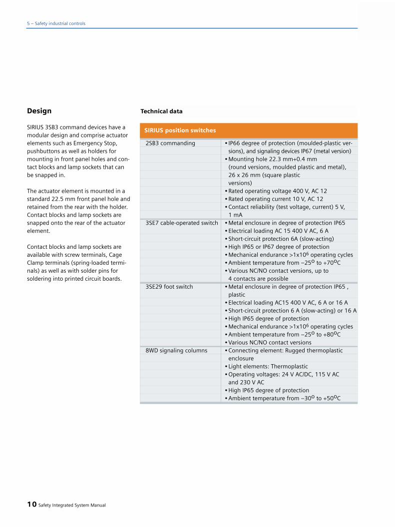
Design
SIRIUS 3SB3 command devices have amodular design and comprise actuatorelements such as Emergency Stop,pushbuttons as well as holders formounting in front panel holes and con-tact blocks and lamp sockets that canbe snapped in.
The actuator element is mounted in astandard 22.5 mm front panel hole andretained from the rear with the holder.Contact blocks and lamp sockets aresnapped onto the rear of the actuatorelement.
Contact blocks and lamp sockets areavailable with screw terminals, CageClamp terminals (spring-loaded termi-nals) as well as with solder pins forsoldering into printed circuit boards.
10 Safety Integrated System Manual
5 – Safety industrial controls
2SB3 commanding • IP66 degree of protection (moulded-plastic ver-sions), and signaling devices IP67 (metal version)
• Mounting hole 22.3 mm+0.4 mm(round versions, moulded plastic and metal), 26 x 26 mm (square plastic versions)
• Rated operating voltage 400 V, AC 12• Rated operating current 10 V, AC 12• Contact reliability (test voltage, current) 5 V,
1 mA3SE7 cable-operated switch • Metal enclosure in degree of protection IP65
• Electrical loading AC 15 400 V AC, 6 A• Short-circuit protection 6A (slow-acting)• High IP65 or IP67 degree of protection• Mechanical endurance >1x10⁶ operating cycles• Ambient temperature from –25o to +70oC• Various NC/NO contact versions, up to
4 contacts are possible3SE29 foot switch • Metal enclosure in degree of protection IP65 ,
plastic• Electrical loading AC15 400 V AC, 6 A or 16 A• Short-circuit protection 6 A (slow-acting) or 16 A• High IP65 degree of protection • Mechanical endurance >1x10⁶ operating cycles• Ambient temperature from –25o to +80oC• Various NC/NO contact versions
8WD signaling columns • Connecting element: Rugged thermoplasticenclosure
• Light elements: Thermoplastic • Operating voltages: 24 V AC/DC, 115 V AC
and 230 V AC• High IP65 degree of protection • Ambient temperature from –30o to +50oC
SIRIUS position switches
Technical data

Overview
Safety relays are used to initiate, as aresult of an actuated contact (e.g. byactuating Emergency Stop, entering ahazardous range), the appropriate re-sponse to safely and reliably protectman, machine and the environment.
Typical plants and systems, in whichsafety relays are used, distinguishthemselves by a low number of sen-sors, a smaller footprint as well as thefact that they are independent of a bussystem (island operation).
SIRIUS safety relays fulfill, on one hand,the requirements of the relevant safetystandards, and on the other hand, therequirements of industry thanks to theircompact design and their reliability.They are an essential component of the Siemens Safety Integrated safetyconcept.
They are subdivided into 2 groups:a) 3TK28 safety relaysb) 3RA71 safety load feeders
Features
SIRIUS safety relays offer users a wholeraft of technical advantages. They areharmonized with one another and canbe cascaded. This permits a high de-gree of flexibility to be realized whenexpanding the safety functions in anexisting plant or system. All of the de-vices that are required to implementsafety circuits - from the sensor throughthe safe evaluation up to the actuator -are available in the SIRIUS productrange. The compactness of the safetyrelays in the SIRIUS optical design allowelectrical cabinets to be configuredwith the same harmonized look & feel.What is especially interesting for com-panies that export their machines is the fact that our SIRIUS safety relaysare certified for worldwide use. Anoth-er significant advantage - especially forthis group of customers - is also thefact that SIRIUS safety relays operatewithout any wear (electronic family ofdevices) or with alternating switchingsequences (devices with mounted con-tactor relays and safety load feeders)achieve and extremely high lifetime.This significantly reduces the numberof service calls.
The features at a glance:
SIRIUS safety relays:
• Monitor safety functions• Are a necessary component of the
safety circuit• Protect man, machine and the
environment
Applications
SIRIUS safety relays are used whereversensor signals must be reliably evaluat-ed and where it is necessary to shutdown hazardous states in a safety-re-lated fashion, e.g.
• Monitoring areas with hazardous motion, e.g. protective door, light grid, light barrier
• Monitoring the movement ofvehicles used at the shop floorusing laser scanners
• Safely stopping and shutting downafter an Emergency Stop has been initiated
These applications are used
• In the automobile industry and thecompanies that supply the automo-bile industry
• In general machine construction• In paper production and printing• In conveyor technology• In the food and beverage industry
Safety Integrated System Manual 11
55.4 SIRIUS safety relays

Product family/productgroups
The family of SIRIUS safety relays issubdivided into devices with basic andaverage functionality. Devices with abasic functionality have one input toconnect a safety sensor. When the sen-sor is triggered, all of the safety-relatedenable circuits are shut down - eitherinstantaneously or with a time delay.Devices with an average level of func-tionality have two or several sensor in-puts. The safety-related enable circuitsof these devices are assigned to sensorinputs via a safety logic.
The 3TK28 / 3RA71 safety relays fulfill,depending on their external circuitry,safety requirements up to Category 4acc. to EN954-1 and SIL 3 acc. to IEC61508 (detailed information about theindividual devices is provided in Cata-log LV10 Order No.: E86060-K1002-A101-A4).
SIRIUS safety relays can be parameter-ized without having to use softwaretools. As a result of the preset function-ality, these devices are ready to operateafter they have been installed.
12 Safety Integrated System Manual
5 – Safety industrial controls

Design
SIRIUS safety relays without integratedcontactor relays are available in twocompact enclosures in the SIRIUS de-sign (22.5 and 45 mm wide). The elec-tronic safety relays with integrated con-tactor relays as well as the safety loadfeeders are 90 mm wide.
All of these devices are designed to besnapped onto 35 mm mounting rails incompliance with EN 50022. 22.5 and45 mm wide devices can also be screw-mounted using additional push-in lugs.Push-in lugs are available as accessorywith Order No. 3RP1903.
The connecting cables are connectedto the device at the top and bottom.The screw or Cage Clamp terminals areaccessible from the front of the device.This feature allows the devices to besimply mounted in a transparent fash-ion. The terminal blocks can be re-moved from the devices. This meansthat when service is required, plantdowntimes can be reduced to an ab-solute minimum.
Functions
SIRIUS safety relays are used to evalu-ate safety sensors and to monitor safe-ty functions.
According to the requirements of theStandards, the devices must ensurethat
a) Faults in the safety relay or in thesensor/actuator circuit must be identi-fied early on in order to prevent loss of the safety function.
b) The safety function is always kepteven if faults occur.
In order to fulfill the above require-ments, there are some significantdifferences between safety relays and non-safety relays.
Basic devices
Monitoring the sensor circuit
Safety relays monitor sensors for cross-circuit faults (2-channel connection)and welded contacts. This is realizeddifferently depending on whether it in-volves an electronic or a relay device.
Cross-circuit fault: For the relaydevice, as a result of the cross-circuitfault, the P potential at the relay is con-nected to ground bypassing the relay.This means that the relay drops-outand the hazard is shut down. For theelectronic version, the electro-mechan-ical sensors are monitored using elec-tronic pulses. If the received pulses donot match the sent pulses, then thedevice shuts down.
Welded sensor contact: Before thedevice can be switched-in, both sensorinputs, for a two-channel connection,must have been opened once, other-wise the device does not switch-in.
Monitoring the actuator circuit
External contactors that are used toswitch the load circuit of the hazardousmotion, are also monitored by the safe-ty relay. This device has inputs to con-nect the feedback signal contacts ofthe contactor. If the contacts are notclosed, the safety relay cannot beswitched-in. The contactors, controlledfrom the device, have positively-drivencontacts. The contactor has load andsignaling contacts that cannot be si-multaneously closed. This functionensures that the safety relay can nolonger be switched-in when a loadcontact welds.
Monitoring its own function
As a result of the redundant inner cir-cuitry of the switching relay, and thefact that the functions mutually moni-tor one another, a fault in a componentresults in the hazardous motion beingshut down. Two safety relays are re-dundantly incorporated in the devices.These safety relays mutually monitortheir functions.The electronic deviceshave two microcontrollers that mutual-ly monitor their function. When a faultoccurs in one of the microcontrollers,the device shuts down the potentiallyhazardous motion. This means thateven if the device has a fault condition,the safety function is kept.
Device faults and operating states aresignaled using an LED on the frontpanel.
Safety Integrated System Manual 13
5

Safety relays are mainly used to imple-ment safety functions in plants andsystems with a small footprint withoutbeing connected to a bus system (islandoperation). These devices are alwaysused in a so-called safety circuit. A safe-ty circuit comprises the functions - DE-TECTING, EVALUATING and RESPOND-ING.
Detecting: Detecting a safety requestusing a sensor - e.g. when an Emer-gency Stop pushbutton is actuated or a protective door opened.
Evaluating: Evaluating the signal fromthe sensor and monitoring the com-plete safety function using the safetyrelay.
Responding: Shutting down a haz-ardous motion
Expansion unit
If the number of safety-related enablecircuits available at the basic unit, isnot sufficient for the particular safetyrelevant application, then this numbercan be increased using an expansionunit (contact multiplier). An expansionunit only has this safety-related inputthat is controlled using a safety-relatedoutput of the basic unit. The basic unitmonitors the function of the expansionunit via the feedback signal contact ofthe expansion unit. Expansion unitsmay only be used in conjunction withbasic units and achieve the same safetycategory as the basic unit.
Press control unit
Presses are one of the most hazardousmachines. In order to protect the oper-ator from e.g. irreversible injury, thetwo-hand operating console forces himto use both hands to operate the pressensuring that both hands are kept out-side the hazardous zone.
The 3TK2834 press control unit is usedto evaluate the two-hand operator con-sole.
The unit detects the following faults:
- Short-circuit, e.g. between the pushbuttons
- Defective relay coils- Broken conductors- Welded contacts
The enable circuits cannot be switched-in, if
- The pushbuttons are not pressedat the same time (w 0.5 s)
- Only one pushbutton is pressed- The feedback circuit is open
14 Safety Integrated System Manual
5 – Safety industrial controls

Integration
The 3TK28 / 3RA71 safety relays arepart of the Safety Integrated system.These relays are preferably used instandalone operation. This means thata bus connection is not required. De-pending on the type of unit beingused, operating states as well as alsodiagnostics data can be signaled to ahigher-level control via the signalingoutputs.
In order to implement the safety-relat-ed functions for more complex plantsand systems, or to expand existingplants or systems, the safety relays canbe cascaded (AND logic). This meansthat the units can be connected to oneanother. This allows, for example, thenumber of safety-related outputs to bemultiplied (with expansion blocks), oralso shutdown groups formed (selec-tive shutdown).
In order that the safety circuit describedabove can function, sensors and actua-tors for the SENSING and RESPONDINGfunctions must be connected to thesafety relay.
For sensors, a differentiation is madebetween sensors with contacts andelectronic sensors.
Sensors with contacts include, e.g.
- Emergency Stop command devices- Hinge-mounted switches- Position switches- Cable-operated switches- Contact mats- etc.
Electro-sensitive protective deviceswith semiconductor outputs include,e.g.
- Light barriers- Light curtains/grids- Laser scanners- etc.
Contactors from the modular SIRIUSsystem are used, for example, as actua-tors. For the 3TK285 and 3RA71 safetyrelays, these contactor relays or loadcontactors are already integrated.
The use of these relays offers two deci-sive advantages:
1. Lower wiring costs thanks to thepre-configured wiring in the factory
2. Fewer possible fault sources whenlocally connecting-up and installing
SIRIUS safety relays can be seamlesslyintegrated in the Totally IntegratedAutomation (TIA) concept. The safetyrelays can be directly controlled fromthe higher-level plant control (e.g. PLC)using the cascading input or via theinput for normal operational switching.This means that normal operatingswitching is possible - i.e. no additionalcontrols are required to switch the load.The safety-related function always hasa higher priority over operational swit-ching.
Safety Integrated System Manual 15
5

Examples
Application:
A processing machine has a protectivedoor and an Emergency Stop function.The tool of the machine must be regu-larly replaced. To do this, the protectivedoor must be opened. It is possible totoggle between maintenance opera-tion and normal operation using a key-operated switch.
This function is implemented using a3TK2845.
Normal operation: When the protec-tive door is opened or the EmergencyStop is actuated all of the outputs ofthe evaluation unit are shut down.
Maintenance operation: Only thehazardous motion is shut down using
the key-operated switch. The auxil-iaries continue to run. When the pro-tective door is opened, the outputsare no longer shut down. When theEmergency Stop is actuated, then, asbefore all of the outputs are shutdown.
16 Safety Integrated System Manual
5 – Safety industrial controls
Fig. 5/13TK2845
Safety logic

Normal operation:
When an Emergency Stop is issued or the protective door actuated, thenoutputs 14, 24 (M1), 34, 44 (M2) areswitched-out. It is only possible topower-up the system again after theEmergency Stop command device hasbeen released, the protective doors and the feedback circuit (RF) at Y64 are closed. After the Emergency Stopcommand device has been actuated,then in addition, the ON button at Y34must be pressed. After the protectivedoor has been closed, the outputs areautomatically switched-in again.
When the key-operated switch is actu-ated (to activate service operation):Outputs 34, 44 (M2) shut down (suit-able to reduce the speed or drive com-ponents are not operational).
Service operation:
The position switches of the protectivedoors are not evaluated. Outputs 34and 44 (M2) are switched-out.
When the Emergency Stop commanddevice is actuated, outputs 14 and 24(M1) are switched-out.
The system can only be powered-upagain after the Emergency Stop com-mand device has been released, thefeedback circuit at Y64 is closed andthe ON pushbutton Y34 is pressed.
Comment:For Category 4, it is not permissible toconnect several position switches in se-ries for the protective door monitoring(fault detection).
Safety Integrated System Manual 17
5Circuit example

18 Safety Integrated System Manual
5 – Safety industrial controls
Additional technical details are provided in the Catalog as well as in the technical documentation in the Internet under:
http://www.siemens.de/automation/service
Basic functionality (1 safety-related sensor can be connected)
Electronic enable circuits
Instantaneous, safety outputs
3TK2840-.BB40 Basis unit 3 -- -- 2 -- -- --
3TK2841-.BB40 Standard unit 4 -- -- 2 -- -- --
Delayed, safety outputs
3TK2842-.BB4. Standard unit with time delay 3s - 300s 4 -- -- 1 1 -- --
Relay contact - enable circuits
Instantaneous, safety outputs
3TK2821-.CB30 Basic unit, auto start 3 3 -- -- -- 1 --
3TK2822-.CB30 Basic unit, auto start 4 2 -- -- -- -- --
3TK2824-..... Basic unit, auto start 4 2 -- -- -- -- --
3TK2825-..... Basic unit, auto start 4 3 -- -- -- 2 --
3TK2823-.CB30 Basic unit, automatic start 4 2 -- -- -- -- --
3TK2830-..... Expansion unit as for basic unit 4 -- -- -- -- --
3TK2834-..... Two-hand control unit 4 2NO + 2NC -- -- -- -- --
3TK2835-..... Run-on test unit -- 3NO + 1NC -- -- -- -- --
Delayed, safety outputs
3TK2828-..... Basic unit, auto start with time delay 0.5 - 30s, 0.05 - 3s 4 2 2 -- -- 1 --
3TK2827-..... Basic unit, monitored start with time delay 0.5 - 30s, 0.05 - 3s 4 2 2 -- -- 1 --
Contactor relay enable circuits
Instantaneous, safety outputs
3TK2850-..... Basic unit 3 3 -- -- -- -- --
3TK2851-..... Basic unit 3 2 -- -- -- 1 --
3TK2852-..... Basic unit 3 6 -- -- -- 1 --
3TK2853-.BB40 Basic unit 3 3 -- -- -- -- --
3TK2856-.BB40 Expansion unit, instantaneous, as for basic unit 6 -- 1 -- 1 --
Delayed, safety outputs
3TK2857-.BB4. Expansion unit with time delay 3s - 300s as for basic unit -- 3 1 -- -- --
Power contactor enable circuits
Instantaneous, safety outputs
3RA710 Basic unit up to Category 3 3 3 -- -- -- * --
3RA711 Basic unit up to Category 4 4 3 -- -- -- * --
3RA712 Expansion unit, instantaneous as for basic unit 3 -- -- -- * --
Delayed, safety outputs
3RA713 Expansion unit with time delay 0.05 - 3 s as for basic unit -- 3 -- -- * --
3RA714 Expansion unit with time delay 0.5 - 30 s as for basic unit -- 3 -- -- * --
Average functionality (2 safety-relative sensors can be connected)
Electronic and relay contact enable circuits
Instantaneous, safety outputs
3TK2845-.BB40 Multi-functional unit, instantaneous 4 2 -- 2 -- -- 1
Delayed, safety outputs
3TK2845-.BB4. Multi-functional unit with time delay 0.05 - 300s 4 1 1 1 1 -- 1
Safety outputs
Max. Category Contacts Electronic Signaling circuit
acc. to EN 954-1 Stop Cat. 0 Stop Cat. 1 Stop Cat. 0 Stop Cat. 1 Contact Electronic
* possible using mounted auxiliary contacts

Safety Integrated System Manual 19
5at Ve=400V, at Ve=400V, at at
50Hz 50Hz U=230 V U= 24 V
24 V 24 V -- -- -- 0.5 A No 22,.
24 V 24 V -- -- -- 1,5 A Yes 22,5
24 V 24 V -- -- -- 1,5 A Yes 22,5
AC/DC 24 V DC 24 V - AC 230 V -- -- 5 A 5 A No 22,5
AC/DC 24 V DC 24 V - AC 230 V -- -- 5 A 5 A No 22.5
AC/DC 24 V, DC 24 V, AC 115 V, AC 230 V DC 24 V - AC 230 V -- -- 5 A 5 A No 22,5
AC/DC 24 V, DC 24 V, AC 115 V, AC 230 V DC 24 V - AC 230 V -- -- 6 A 6 A No 45
AC/DC 24 V DC 24 V - AC 230 V -- -- 5 A 5 A No 22.5
AC/DC 24 V, AC 115 V, AC 230 V DC 24 V - AC 230 V -- -- 5 A 5 A No 45
DC 24 V, AC 24 V, AC 115 V, AC 230 V DC 24 V - AC 230 V -- -- 6 A 6 A No 45
DC 24 V, AC 24 V, AC 115 V, AC 230 V DC 24 V - AC 230 V -- -- 5 A 5 A No 45
DC 24 V, AC 24 V, AC 115 V, AC 230 V DC 24 V - AC 230 V -- -- 5 A 5 A No 45
DC 24 V, AC 24 V, AC 115 V, AC 230 V DC 24 V - AC 230 V -- -- 5 A 5 A No 45
DC 24 V, AC 24 V, AC 115 V, AC 230 V DC 24 V, AC 230 V, AC 600 V -- -- 6 A 10 A No 90
DC 24 V, AC 24 V, AC 115 V, AC 230 V DC 24 V, AC 230 V, AC 600 V -- -- 6 A 10 A No 90
DC 24 V, AC 230 V DC 24 V, AC 230 V, AC 600 V -- -- 6 A 10 A No 90
DC 24 V DC 24 V, AC 230 V, AC 600 V -- -- 6 A 10 A No 90
DC 24 V DC 24 V, AC 230 V, AC 600 V -- -- 6 A 10 A -- 90
DC 24 V DC 24 V, AC 230 V, AC 600 V -- -- 6 A 10 A -- 90
AC 690 V DC 24 V, AC 230 V -- -- No 90
AC 690 V DC 24 V, AC 230 V -- -- Yes 90
AC 690 V DC 24 V, AC 230 V -- -- -- 90
AC 690 V DC 24 V, AC 230 V -- -- -- 90
AC 690 V DC 24 V, AC 230 V -- -- -- 90
24 V 24 V, 230 V -- -- 2 A 1,5 A Yes 45
24 V 24 V, 230 V -- -- 2 A 1.5 A Yes 45
Rated control supply voltage / V Rated operating voltage / V Switching capability Electronic sensors Enclosure width / mm
AC-1 AC-3 AC-15 DC-13

Reference - link
Overview, features / customer benefitsas well as function design and applica-tions were explained in Chapter 4.2(Safety-related communications using
standard fieldbuses; Section ASIsafe).The product spectrum will be discussedin detail and a typical structure shownin the following.
20 Safety Integrated System Manual
5 – Safety industrial controls
5.5 ASIsafe
The safety monitor is the core element of ASIsafe. A safety-related application is configured using a PC. In this case, various application-specific operating modes can be selected.These include, e.g. Emergency Stop function, protective door tumbler mechanism as well as the selection of Stop Category 0 or 1. In order to be able to fully utilize ASI diagnostic possibilities, the monitor can be optionally operated with the AS interface address. There are two monitor versions:• Basis safety monitor• Enhanced safety monitorBoth expansion stages are available with enable circuits implemented with either one or two channels.
Safety monitors
Emergency Stop command devices can be directly connected using the standard ASI-Interfacewith safety-related communications. This applies to the SIRIUS 3SB3 Emergency Stop command device for front panel mounting and for mounting in an enclosure. An Emergency Stop command device mounted in a front panel can be directly connected to the AS-Interface via a safety module.
SIRIUS Emergency Stop
Different enclosures with 3SB3 command devices with Emergency Stop can be directly connected to ASIsafe.Customer-specific arrangements of the command and signaling devices inside the enclosure can also be ordered.
Emergency Stop in enclosures
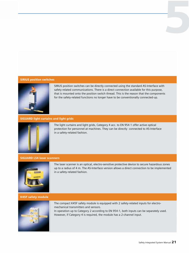
Safety Integrated System Manual 21
SIRIUS position switches can be directly connected using the standard AS-Interface withsafety-related communications. There is a direct connection available for this purpose,that is mounted onto the position switch thread. This is the reason that the components for the safety-related functions no longer have to be conventionally connected-up.
SIRIUS position switches
The light curtains and light grids, Category 4 acc. to EN 954-1 offer active optical protection for personnel at machines. They can be directly connected to AS-Interface in a safety-related fashion.
SIGUARD light curtains and light grids
The laser scanner is an optical, electro-sensitive protective device to secure hazardous zones up to a radius of 4 m. The AS-Interface version allows a direct connection to be implemented in a safety-related fashion.
SIGUARD LS4 laser scanners
The compact K45F safety module is equipped with 2 safety-related inputs for electro-mechanical transmitters and sensors.In operation up to Category 2 according to EN 954-1, both inputs can be separately used. However, if Category 4 is required, the module has a 2-channel input.
K45F safety module
5

All important standards and regula-tions are fulfilled, e.g.:
• IEC 61508 (up to SIL 3),• EN 954 (up to Category 4)
Technical data
There are two safety monitor versions:
• Basis safety monitor• Enhanced safety monitor
Both expansion stages are availablewith enable circuits utilizing either oneor two channels.
Table: Comparison between the basissafety monitor - expanded safety moni-tor
22 Safety Integrated System Manual
5 – Safety industrial controls
The compact K60F safety module is equipped with 2 safety-related inputs for electro-mechanical transmitters and sensors.Both inputs can be separately used for operation up to Category 2 acc. to EN 954-1; if Category 4 is required the module has a 2-channel input. In addition, the module also has 2 non safety-related outputs. K60F is available in two versions:• Power supply for the outputs via the yellow cable• Auxiliary power supply for the outputs via the black cable (Vaux.)
K60F safety-related module
The SlimLine S22.5F safety module has 2 “safety” inputs for electro-mechanical transmitters and sensors. This allows safety-related signals to be connected to ASIsafe in distributedlocal electrical cabinets and boxes.Both inputs can be separately used for operation up to Category 2. If Category 4 is required, the module also has a 2-channel input
S22.5F safety module
No. of monitoring blocks 32 48
No. of OR logic gates (inputs) 2 6
No. of AND logic gates (inputs) - 6
Space retainer for monitoring blocks Yes Yes
De-activating monitoring blocks Yes Yes
Fault release Yes Yes
Hold diagnostics Yes Yes
A/B slaves for acknowledgment Yes Yes
Safety time function No Yes
Function “Key” No Yes
Contact de-bounce No Yes
Basis safety Enhancedmonitor safety monitor
Safety Monitor
3RK1 105
Rated operating current
• Ie/AC-12 to 250 V, 3 A
• Ie/AC-15 115 V, 3 A
230 V, 3 A
• Ie/DC-12 to 24 V, 3 A
• Ie/DC-13 24 V, 1 A
115 V, 0.1 A
230 V, 0.05 A
• Response time (worst case) in ms <_40
• Ambient temperature in degrees in °C 0 ... +60
• Storage temperature in °C -40 ... +85

Example - packaging machine
A typical ASIsafe application is shownin the following diagram:
Description of the sequence:
Empty boxes are transported alongconveyor belt 1 for filling. The productsto be placed in the boxes are moved tothe robot using conveyor belt 3.This fills the empty boxes. The filledboxes are then transported away onconveyor belt 2.
Protective devices and equipment:
The robot has a protective fence aroundit to protect personnel against injury.The light grid ensures that the applica-tion is shut down within the protectivefence.The cable-operated switch allows con-veyor belt 1 to be shut down.The Emergency Stop powers-down thecomplete plant or system in a safety-related fashion.A door is provided in the safety fencefor maintenance purposes. This door is monitored using a protective doortumbler mechanism. When the robotsystem is entered through the door, the application inside the protectivefence is shut down.
Implementation with ASIsafe:
The circuit for an AS-Interface solutionis shown in the adjacent diagram.Safety monitor 1 switches the powerfor motor 1.Safety monitor 2 switches the powerfor motors 2 and 3.
Safety Integrated System Manual 23
5
Fig. 5/2
Combination of safety slaves using as an example a packaging machine.
This indicates the specific, safety-related shutdown of sub-areas.
Fig. 5/3
Forming groups with ASIsafe
ASIsafe allows safety-related signals to be appropriately grouped.This means that the safety slaves canbe assigned to the safety monitors. The protective door monitoring and the light barriers are assigned to safety monitor 2 (bright blue arrow).The cable-operated command device is assigned safety monitor 1 (bluearrow). The Emergency Stop commanddevice is assigned both safety monitors(red arrow).
This means that the cable-operatedswitch shuts down safety monitor 1 via a safety module.The light barriers and the protectivedoor shut down the application withinthe protective fence via safety monitor 2.
The complete system can be shut downvia the Emergency Stop command de-vice - that is assigned to both safetymonitors.
Overview
The ET 200S Safety Motor Starter Solu-tions comprise the following:
• Safety modules• ET 200S Motor Starters, Standard• ET 200S Motor Starters, High Feature• ET 200S Failsafe Motor Starters
The devices have been designed foruse in the distributed ET 200S I/O sys-tem. The motor starters are equippedwith electrically isolating contacts.
These Safety Motor Starter Solutionscan protect and switch any three-phaseload without any fuses being required.All of the inputs and outputs necessaryto connect the motor starter and safetysystem to the higher-level control arealready integrated. They are also opti-mally suited for use in distributed elec-trical cabinets (degree of protection IP20)as a result of the communications in-terface and the extensive diagnosticfunctionality.
With ET 200S Safety Motor Starter Solu-tions, the complex and therefore cost-intensive engineering and wiring costswhen compared to conventional safetysystems are eliminated. ET 200S SafetyMotor Starter Solutions are designedfor Category 4 acc. to EN 954-1 andSIL 3 (IEC 61508).
Applications
ET 200S Motor Starter Solutions arepreferably used in all sectors of pro-duction and process automation wherethe reduction of production times orthe increase of plant availability plays a significant role.
1. ET 200S Motor Starter SolutionsLocal, from the perspective of thesafety system, should be limited to one station.
2. On the other hand, ET 200S MotorStarter Solutions PROFIsafe are fre-quently used in more complex safetysystem applications that are networkedwith one another.
Technical requirements
• PROFIBUS or PROFINET If the ET 200S Safety Motor Starter Solution PROFIsafe is required, thenin addition, a safety-related SIMATIC control and PROFIBUS or PROFINET with the PROFIsafe profile as commu-nications medium are required.
Customer requirements
• Safety direct or reversing startersup to 7.5 kW / at 500 V acc. to DINVDE 0106, Part 1014 – IEC 60947-1,EN 60947-1 and for 600 V acc. toUL, CSA must be able to be simply integrated into standard automation environments.
• Seamless, integrated total systemand complete safety technologyfrom a single source.
• Simplified engineering thanks toseamless and integrated tools.
24 Safety Integrated System Manual
5 – Safety industrial controls
5.6 ET 200S SafetyMotor Starter Solution

• Safety-related components must be able to be simply connected - e.g. Emergency Stop command devices, protective door monitoring devices or light curtains via safety modules.
• For complex requirements placed on the safety system, a favorably-priced solution in comparison to conventio-nal systems with load feeders and discrete safety technology.
• Reduced costs for testing anddocumentation.
• Fast configuration and commissioning• A system can be easily expanded with
lower engineering and wiring costs.
• High degree of availability thanks to extensive diagnostics (fast trouble-shooting) and service-friendliness (plug-in modules / hot swapping) * .
Features
Our ET 200S Safety Motor Starter Solu-tions allow safety-related direct or re-versing starters to be used in the dis-tributed SIMATIC ET 200S I/O system.Applications involving machines andplants can be optimally emulated thanksto the finely modular system architec-ture.
The motor starters are suitable for swit-ching and protecting three-phase loads.Motor Starters, Standard: Max. 5.5 kW(AC 500 V) with self-establishing powerbus up to 40 A
Motor Starters, High Feature: Max. 7.5kW (500 V AC) with self-establishingpower bus up to 50 AFailsafe Motor Starters: Max. 7.5 kW (500 V AC) with self-establishing powerbus up to 50 A All of the motor starters can be option-ally expanded using modules to controlbrakes integrated in the motor.
Safety Integrated System Manual 25
Fig. 5/4
ET 200S Motor Starter
5
* Hot swapping: Devices are replaced in operation
without having any effect on the operational
CPU or motor starter.

ET 200S Safety Motor Starter Solutionscan also be combined, within an ET 200Sstation - with SIMATIC ET 200S FC fre-quency converters (refer to Chapter9.3). Also in this case, safety-relatedcomponents can be combined withnon safety-related components.
The complete SIMATIC ET 200S systemis UL/CSA certified.TÜV (German Technical Inspectorate)has certified our ET 200S Failsafe MotorStarters.
ET 200S Safety Motor StarterSolutions Local Wiring-oriented sensor assignment:The logic of the safety-relatedfunctions is implemented using the wiring
Several safety circuits can be easilyconfigured using ET 200S Safety MotorStarter Solutions Local. The safety sen-sor systems are directly connected tothe safety modules. These safety mod-ules handle the task of the otherwiseobligatory safety relays and dependingon the selected function safely shutdown the downstream motor starters.The cross connections that are requiredare already integrated in the systemand no additional wiring is required. It goes without saying that ET 200SMotor Starters can also be used in con-junction with external safety relays orwith ASIsafe.
When compared to conventional safetysystems, the ET 200S Safety MotorStarter Solution Local saves a consider-able about of wiring when it comes tolocal safety applications.
There are three versions:
Local safety applications - ET 200S Motor Starters, Standard:Group shutdown
• Several monitored motor starters up to 5.5 kW can be quickly and simul-taneously combined in a distributedI/O system to form one or several safety-related groups. This is the reason that even more complex safety-relevant applications can be handled using the ET 200S Safety Motor Starter Solutions Local (up to 42 standard motor starters canbe combined in just one station).
26 Safety Integrated System Manual
5 – Safety industrial controls
Fig. 5/5
ET 200S Safety Motor Starter Solution Local (with Motor Starters, Standard) F-Kits 1 or 2
are required. From Category 3 EN 954-1: Redundantly switching, external supply contac-
tor is required
Fig. 5/6
Distributed electrical enclosure with ET
200S Safety Motor Starter Solution Local
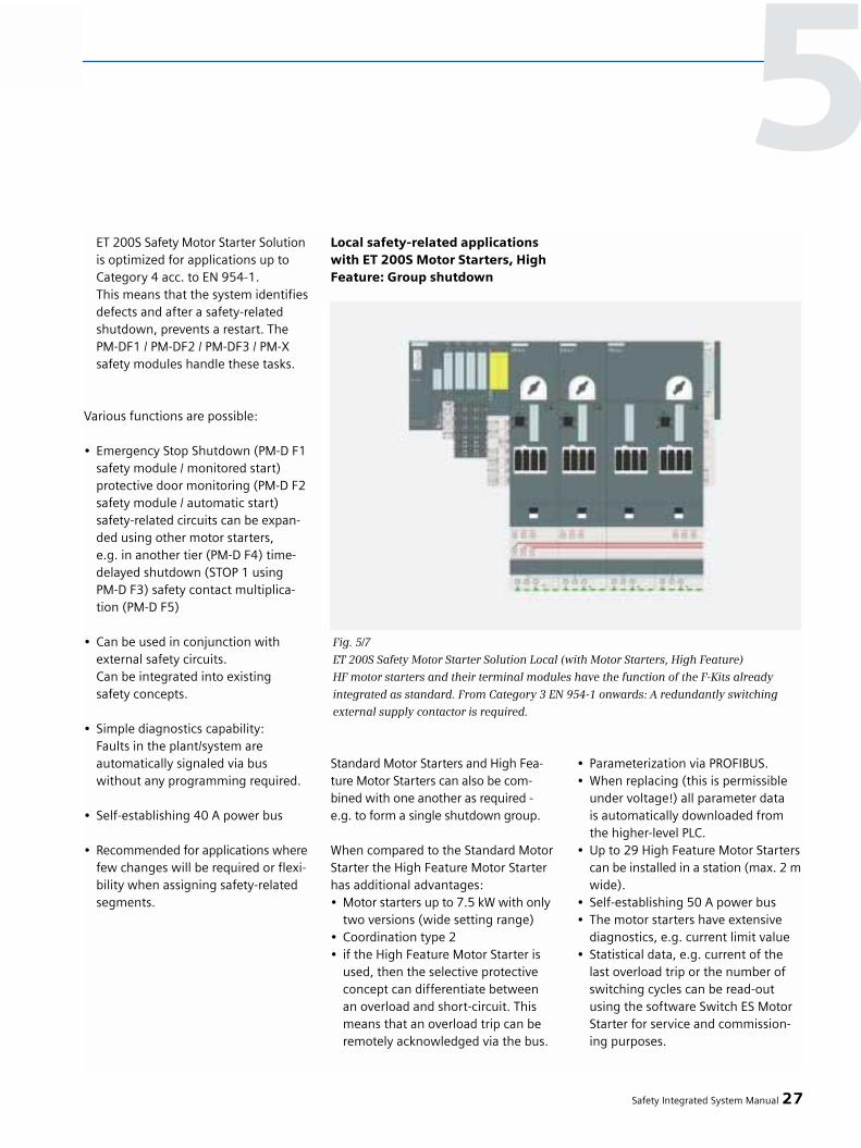
ET 200S Safety Motor Starter Solutionis optimized for applications up to Category 4 acc. to EN 954-1.This means that the system identifiesdefects and after a safety-related shutdown, prevents a restart. The PM-DF1 / PM-DF2 / PM-DF3 / PM-Xsafety modules handle these tasks.
Various functions are possible:
• Emergency Stop Shutdown (PM-D F1 safety module / monitored start)protective door monitoring (PM-D F2 safety module / automatic start)safety-related circuits can be expan-ded using other motor starters, e.g. in another tier (PM-D F4) time- delayed shutdown (STOP 1 usingPM-D F3) safety contact multiplica-tion (PM-D F5)
• Can be used in conjunction with external safety circuits. Can be integrated into existingsafety concepts.
• Simple diagnostics capability: Faults in the plant/system areautomatically signaled via buswithout any programming required.
• Self-establishing 40 A power bus
• Recommended for applications wherefew changes will be required or flexi-bility when assigning safety-related segments.
Local safety-related applicationswith ET 200S Motor Starters, HighFeature: Group shutdown
Standard Motor Starters and High Fea-ture Motor Starters can also be com-bined with one another as required -e.g. to form a single shutdown group.
When compared to the Standard MotorStarter the High Feature Motor Starterhas additional advantages:• Motor starters up to 7.5 kW with only
two versions (wide setting range)• Coordination type 2• if the High Feature Motor Starter is
used, then the selective protective concept can differentiate betweenan overload and short-circuit. This means that an overload trip can be remotely acknowledged via the bus.
• Parameterization via PROFIBUS.• When replacing (this is permissible
under voltage!) all parameter data is automatically downloaded from the higher-level PLC.
• Up to 29 High Feature Motor Starterscan be installed in a station (max. 2 mwide).
• Self-establishing 50 A power bus• The motor starters have extensive
diagnostics, e.g. current limit value• Statistical data, e.g. current of the
last overload trip or the number of switching cycles can be read-out using the software Switch ES Motor Starter for service and commission-ing purposes.
Safety Integrated System Manual 27
Fig. 5/7
ET 200S Safety Motor Starter Solution Local (with Motor Starters, High Feature)
HF motor starters and their terminal modules have the function of the F-Kits already
integrated as standard. From Category 3 EN 954-1 onwards: A redundantly switching
external supply contactor is required.
5

28 Safety Integrated System Manual
5 – Safety industrial controls
Fig. 5/8
ET 200S Safety Motor Starter Solution Local with Failsafe Motor Starters
(PM-D F1, PM-D F2 application)
Local safety applications with Failsafe Motor Starters: Selective shutdown.
Fig. 5/9
ET 200S Safety Motor Starter Solution Local (with Failsafe Motor Starter and PM-D FX1)
An external supply contactor is not required as redundant second shutdown element,
as the motor circuit-breaker is used.
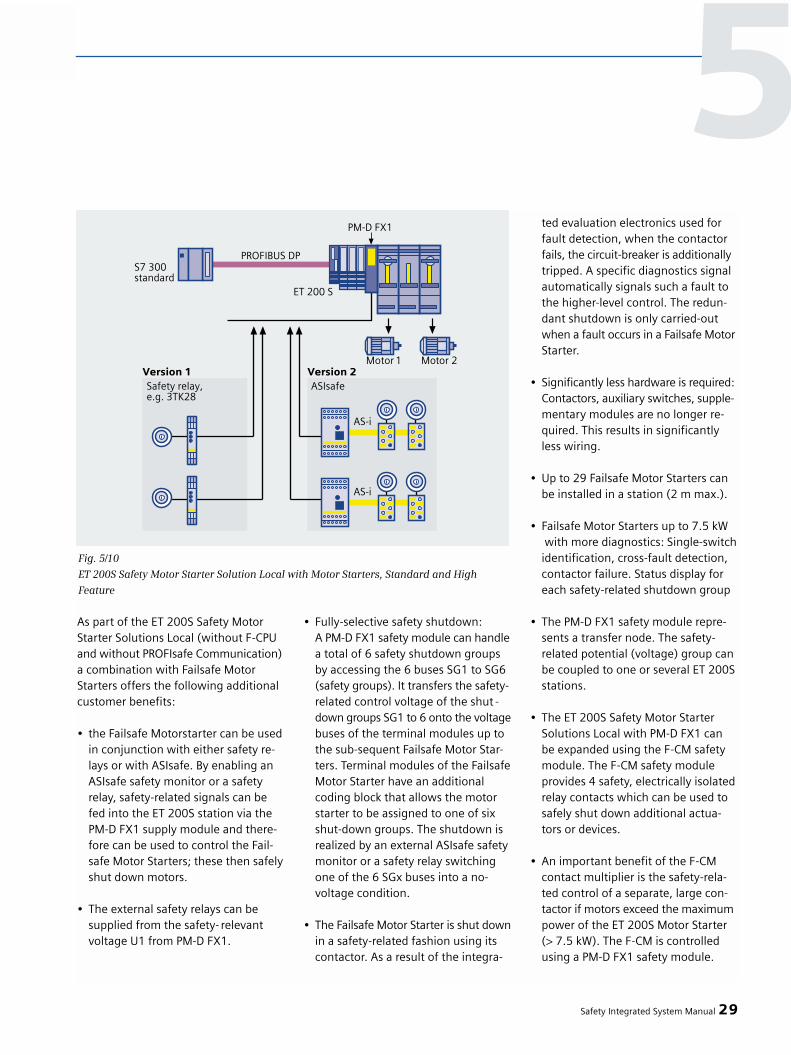
As part of the ET 200S Safety MotorStarter Solutions Local (without F-CPUand without PROFIsafe Communication)a combination with Failsafe MotorStarters offers the following additionalcustomer benefits:
• the Failsafe Motorstarter can be usedin conjunction with either safety re-lays or with ASIsafe. By enabling an ASIsafe safety monitor or a safety relay, safety-related signals can be fed into the ET 200S station via thePM-D FX1 supply module and there-fore can be used to control the Fail-safe Motor Starters; these then safelyshut down motors.
• The external safety relays can be supplied from the safety- relevant voltage U1 from PM-D FX1.
• Fully-selective safety shutdown: A PM-D FX1 safety module can handlea total of 6 safety shutdown groups by accessing the 6 buses SG1 to SG6 (safety groups). It transfers the safety-related control voltage of the shut -down groups SG1 to 6 onto the voltagebuses of the terminal modules up to the sub-sequent Failsafe Motor Star-ters. Terminal modules of the FailsafeMotor Starter have an additional coding block that allows the motor starter to be assigned to one of six shut-down groups. The shutdown is realized by an external ASIsafe safety monitor or a safety relay switching one of the 6 SGx buses into a no-voltage condition.
• The Failsafe Motor Starter is shut downin a safety-related fashion using its contactor. As a result of the integra-
ted evaluation electronics used for fault detection, when the contactor fails, the circuit-breaker is additionallytripped. A specific diagnostics signal automatically signals such a fault to the higher-level control. The redun-dant shutdown is only carried-outwhen a fault occurs in a Failsafe Motor Starter.
• Significantly less hardware is required: Contactors, auxiliary switches, supple-mentary modules are no longer re-quired. This results in significantly less wiring.
• Up to 29 Failsafe Motor Starters can be installed in a station (2 m max.).
• Failsafe Motor Starters up to 7.5 kW with more diagnostics: Single-switchidentification, cross-fault detection, contactor failure. Status display for each safety-related shutdown group
• The PM-D FX1 safety module repre-sents a transfer node. The safety-related potential (voltage) group can be coupled to one or several ET 200Sstations.
• The ET 200S Safety Motor Starter Solutions Local with PM-D FX1 can be expanded using the F-CM safetymodule. The F-CM safety moduleprovides 4 safety, electrically isolatedrelay contacts which can be used to safely shut down additional actua-tors or devices.
• An important benefit of the F-CM contact multiplier is the safety-rela-ted control of a separate, large con-tactor if motors exceed the maximumpower of the ET 200S Motor Starter (> 7.5 kW). The F-CM is controlled using a PM-D FX1 safety module.
Safety Integrated System Manual 29
Fig. 5/10
ET 200S Safety Motor Starter Solution Local with Motor Starters, Standard and High
Feature
5

ET 200S Safety Motor Starter Solutions PROFIsafeAs part of the distributed safetyconcept, the assignment of sensorsand actuators can be programmed:This means that every safety func-tion can be implemented.
If a safety-related SIMATIC CPU is used,then the ET 200S can be used as safety-related I/O. However, conventionaltechnology can be mixed with moduleswith safety-related functions in such astation with motor starter and input/output modules.
The safety-related functions are avail-able in the complete network. Thismeans that the ET 200S Safety MotorStarter Solutions PROFIsafe permits theselective shutdown of a group of Stan-dard, High Feature or Failsafe MotorStarters. It does not matter to which I/Ostation the safety-related command de-vices are connected. This is why this so-lution offers a degree of flexibility thathas been unknown up until now andfar less wiring for applications with alarge, extensive footprint or those thatonly sporadically have to be modifiedor changed when assigning the safetysegments. ET 200S Motor Starter Solu-tions PROFIsafe is optimally suited forsafety concepts with Cat. 2 to 4 acc. toEN 954-1, SIL 2 and 3 acc. to IEC 61508.
There are three versions:
Safety Applications with safety-related communications and MotorStarters, Standard: Group shutdown
The F-CM safety module (contact multi-plier) is an important supplement tothe fail-safe ET 200S I/O modules. Forexample, to provide an interface be-tween an ET 200S station and plants or systems utilizing conventional safetysystems - for instance, robots.
An F-CM safety module can be assignedto a safety shutdown group SG1 to SG6of a PM-D F PROFIsafe safety moduleand comprises four separate, electrical-ly isolated enable circuits as NO contact. At each ON – OFF cycle of the contactmultiplier, the contacts of the F-CM arechecked to ensure that they open andclose correctly. If welded contacts areidentified in any enable circuit of the F-CM, then the device is prevented from
restarting as a result of the positively-driven contacts. In this case, an appro-priate diagnostics signal is transferredto the higher-level control.
The F-CM safety module forms an inter-face between a PROFIsafe applicationand a wiring-oriented motor startergroup.This means that standard motorsstarters can be used and safely shutdown via PROFIsafe.
• Favorably-priced implementationof a shutdown group
• A redundant switching, external supply contactor is used via thePM-X safety module (only required for Cat. 3 or 4 EN 954-1)
• The feedback circuit is monitoredvia PM-D F2
• Motor protection up to 5.5 kW usinga circuit-breaker
• Behavior for CPU STOP can be set• Group diagnostics
30 Safety Integrated System Manual
5 – Safety industrial controls
Fig. 5/11
ET 200S Safety Motor Starter Solution PROFIsafe (with Motor Starters, Standard)
Additional F-Kits 1 or 2 required. From Category 3 EN 954-1: Redundant switching,
external supply contactor is required
Circuitbreaker
Supplycontac-tor

Safety applications with safety-related communications and MotorStarters, High Feature: Group shut-down
When compared to Standard MotorStarters, High Feature Motor Startershave the following advantages:
• The feedback circuit is already inte-grated (an F-Kit is not required)
• Electronic motor protection up to 7.5 kWBehavior under overload conditionsthermal motor modelBehavior when the current limit value is violatedBehavior when detecting a zero currentBehavior when imbalance occursBehavior for a CPU STOP
• Remote reset after overload tripis possible
• Group diagnostics• Extended individual diagnostics
Safety applications with safety-related communication and withFailsafe Motor Starters: Completelyselective shutdown
The motor starters are assigned to oneof six safety-related segments withinan ET 200S station. For plants and systems with a distrib-uted architecture, the shutdown signalsof these safety segments are preferablyfrom a higher-level safety-related con-trol via PROFIsafe. This signifies thehighest possible degree of flexibilitywhen assigning motor starters to dif-ferent safety circuits. As an alternative,an ET 200S interface module with safe-ty-related CPU can be controlled. This is especially recommended for local,limited applications and more basicsafety interlocks. It is also possible to
control external safety systems such ase.g. the AS-Interface.If a station is expanded by additionalshutdown groups, then the PROFIsafe
structure with the failsafe motor startersis more favorably priced than a PM-DF1/2-based solution.
Safety Integrated System Manual 31
Fig. 5/12
ET 200S Safety Motor Starter Solution PROFISAFE (with Motor Starters, High Feature)
F-Kits 1 and 2 are not required: High Feature Motor Starters and their terminal modules
have the function of the F-Kits integrated as standard. From Category 3 EN 954-1 onwards:
A redundant switching external supply contactor is required
Fig. 5/13
ET 200S Safety Motor Starter Solution PROFISAFE (with Motor Starters, High Feature)
F-Kits 1 and 2 are not required: The redundant, second shutdown element is no longer
a main contactor, but a circuit-breaker with auxiliary release integrated into the motor
starters.
5Circuitbreaker
Supplycontac-tor
Supply
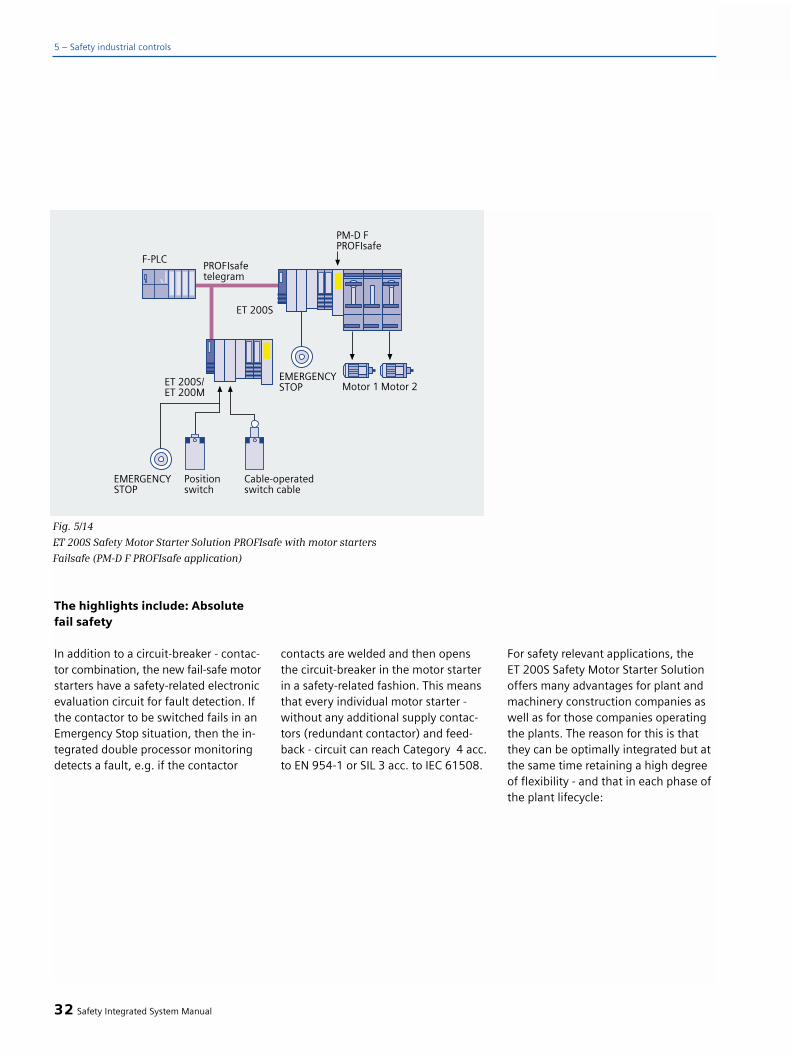
The highlights include: Absolutefail safety
In addition to a circuit-breaker - contac-tor combination, the new fail-safe motorstarters have a safety-related electronicevaluation circuit for fault detection. Ifthe contactor to be switched fails in anEmergency Stop situation, then the in-tegrated double processor monitoringdetects a fault, e.g. if the contactor
contacts are welded and then opensthe circuit-breaker in the motor starterin a safety-related fashion. This meansthat every individual motor starter -without any additional supply contac-tors (redundant contactor) and feed-back - circuit can reach Category 4 acc.to EN 954-1 or SIL 3 acc. to IEC 61508.
For safety relevant applications, the ET 200S Safety Motor Starter Solutionoffers many advantages for plant andmachinery construction companies aswell as for those companies operatingthe plants. The reason for this is thatthey can be optimally integrated but atthe same time retaining a high degreeof flexibility - and that in each phase ofthe plant lifecycle:
32 Safety Integrated System Manual
5 – Safety industrial controls
Fig. 5/14
ET 200S Safety Motor Starter Solution PROFIsafe with motor starters
Failsafe (PM-D F PROFIsafe application)

Safety Integrated System Manual 33
5Phase 1: DESIGN and ENGINEERING
Lower costs for • Motor starters are-parameterized and engineering and documented using the standard STEP7 tooldocumentation • All motor starter control functions can be
configured/engineered using the PLC• Pre-configured programming examples for the
safety-related functions• Fewer components: e.g. only 2 versions of
Motor Starters, High Feature or Failsafeup to 7.5 kW with wide setting ranges
Faster reproduc- Software solution can, contrary to a hardwareibility solution, be simply multipliedHigher degree of • Fully-selective safetyflexibility shutdown.
• The logic of the safety function is implementedin the software – not in the wiring
Phase 2: INSTALLATION and COMMISSIONINGSignificantly faster • Optimum cabinet design and layout bymounting and installa- horizontally mounting motor starters “side-by-tion side” without de-rating up to 60º C
• Up to 90% less control/safety wiring thanks tothe safety system already integrated in the ET 200S and the data coupling with S7-300F via PROFIsafe
• Thanks to the fast installation system of the ET 200S with self-establishing power bus, cableducts are eliminated, terminals are replaced
• All supply voltages are only connected once andare then automatically connected to the nextmodules.
• All motor starters are completely connected-up only the motor has to be connected.
Lower space require- • More compact solutionment (fewer/smaller • Separate components that were previously used areelectrical cabinets) eliminated) due to the integrated
redundancy and the integrated safety monitoringSignificantly faster • Simple testing thanks to standardization andcommissioning a modular plant concept
• Significantly fewer wiring errors are possible• Interface for ES Motor Starter Software Switch
More favorably priced and Motor starters, safety modules and programmingsimpler acceptance pro- examples (F library) have been certified by the cedure (Machinery Directive) TÜV (German Technical Inspectorate)Lower purchasing costs Often, the plug-on motor starters are only
required weeks later. This reducesthe amount of capital that is tied-up.
Requirements Plant builders Plant operating Featurethat are fulfilled and machine OEMs companies
Design &
Engineering
Installation&
Commissioning
Modernization&
Expansion
“Life cycle of industrial equipment”
Operation
Service & Main-
tenance
q
q
q
q
q
q
q
q
q
q
q
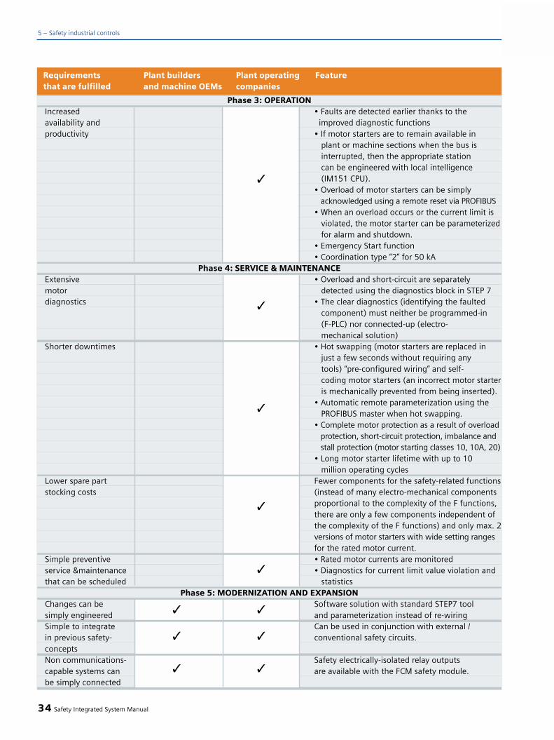
34 Safety Integrated System Manual
5 – Safety industrial controls
Phase 3: OPERATIONIncreased • Faults are detected earlier thanks to theavailability and improved diagnostic functionsproductivity • If motor starters are to remain available in
plant or machine sections when the bus is interrupted, then the appropriate station can be engineered with local intelligence (IM151 CPU).
• Overload of motor starters can be simplyacknowledged using a remote reset via PROFIBUS
• When an overload occurs or the current limit isviolated, the motor starter can be parameterized for alarm and shutdown.
• Emergency Start function• Coordination type “2” for 50 kA
Phase 4: SERVICE & MAINTENANCEExtensive • Overload and short-circuit are separatelymotor detected using the diagnostics block in STEP 7diagnostics • The clear diagnostics (identifying the faulted
component) must neither be programmed-in(F-PLC) nor connected-up (electro-mechanical solution)
Shorter downtimes • Hot swapping (motor starters are replaced injust a few seconds without requiring anytools) “pre-configured wiring” and self-coding motor starters (an incorrect motor starteris mechanically prevented from being inserted).
• Automatic remote parameterization using thePROFIBUS master when hot swapping.
• Complete motor protection as a result of overloadprotection, short-circuit protection, imbalance and stall protection (motor starting classes 10, 10A, 20)
• Long motor starter lifetime with up to 10 million operating cycles
Lower spare part Fewer components for the safety-related functionsstocking costs (instead of many electro-mechanical components
proportional to the complexity of the F functions,there are only a few components independent ofthe complexity of the F functions) and only max. 2versions of motor starters with wide setting rangesfor the rated motor current.
Simple preventive • Rated motor currents are monitoredservice &maintenance • Diagnostics for current limit value violation andthat can be scheduled statistics
Phase 5: MODERNIZATION AND EXPANSIONChanges can be Software solution with standard STEP7 toolsimply engineered and parameterization instead of re-wiringSimple to integrate Can be used in conjunction with external / in previous safety- conventional safety circuits. conceptsNon communications- Safety electrically-isolated relay outputscapable systems can are available with the FCM safety module.be simply connected
Requirements Plant builders Plant operating Featurethat are fulfilled and machine OEMs companies
q
q
q
q
q
q
q
q
q
q
q

Applications
ET 200S Safety Motor Starter SolutionsLocal is used in all plants and systemswhere:
• Three-phase loads up to 7.5 kW are to be protected and operated.
• A peripheral (I/O system) in conjunc-tion with a non safety-related PLC with degree of protection IP20 with PROFIBUS DP or PROFInet interfaceis practical.
• Local safety-related systems are required in plants and parts of plantswith a limited footprint for safety-relatedload shutdown.
• No F-CPU is to be used.
ET 200S Safety Motor Starter SolutionPROFIsafe is used in all plants, in which:
• Three-phase loads up to 7.5 kW are to be protected and operated.
• A peripheral (I/O) system in conjunc-tion with safety-related PLC with PROFIBUS DP interface is practical.
• Safety-related communications.capable load shutdown is required.
• Optimum for use in plants andsystems with an extensive footprint
This solution is predestined for the distributed safety concept.
Configuration example
comprising a control with peripherals(I/O), operator panel, laser scanner andlight curtain.
Safety Integrated System Manual 35
5
Fig. 5/15

ET 200S Safety Motor Starter (either with or without PROFIsafe)Solutions are mainly used in theproduction industry, but also in the process industry.
Here is an example for a machine toolin the production industry:
• SINUMERIK/SIMODRIVE as PROFIsafemaster
• 1 ET 200S reversing starter for the revolver head
• 1 direct starter for the tool lubricating pump
• Emergency Stop and hazardouszone monitoring
The following modules are available:
PM-D F PROFIsafe
Safety-related PROFIsafe power modulewith 6 integrated, safety-related shut-down buses (SIL 3), 24 V and 2 A tosafely shut down downstream failsafemotor starters or contact multiplierswhen internally controlled via PROFIsafe.
PM-D F X1
Safety-related power module (feederterminal module) with 6 integratedsafety shutdown buses (SIL 3), 24 Vand 2 A to safely shut down down-stream failsafe motor starters or con-tact multipliers, when shutting downvia external safety relays with electri-cally isolated contacts (e.g. 3TK28,ASIsafe safety monitor, relay outputs of safety-related PLCs etc.).
F-CM
Safety-related contact multiplier with 4 (SIL 3) outputs for 24 V and 2 A
Motorstarter Failsafe
Safety-related direct and reversing starterwith a switching capability up to 7.5kW, with redundant electrical isolation
An ET 200S configurator allows the distributed ET 200S I/O system to bequickly, simply and correctly config-ured.
Advantages:
• Parts lists and ordering data areautomatically generated.
• Fast preliminary calculation.• Transparent, graphic representation.• Automatic configuration and
structure test.
The ET 200S configurator is availablefree-of-charge on the Catalog CD-ROMCA01 and also through the Internet.
36 Safety Integrated System Manual
5 – Safety industrial controls
Fig. 5/16
Application example in the production industry

Structure
Examples
Safety Integrated System Manual 37
Fig. 5/17
Structure of an ET 200S Safety Motor Starter Solution Local with Standard Motor Starters
and mounted F-Kits station
Fig. 5/18
Configuration of an ET 200S Safety Motor Starter Solution PROFIsafe with Failsafe Motor
Starters
5
Fig. 5/19
Distributed electrical cabinet with ET 200S
Failsafe Motor Starters
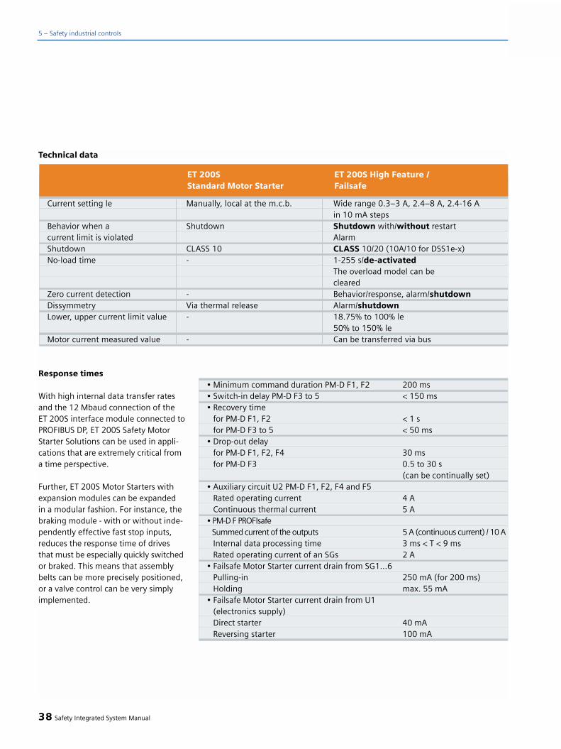
Response times
With high internal data transfer ratesand the 12 Mbaud connection of theET 200S interface module connected toPROFIBUS DP, ET 200S Safety MotorStarter Solutions can be used in appli-cations that are extremely critical froma time perspective.
Further, ET 200S Motor Starters withexpansion modules can be expanded in a modular fashion. For instance, thebraking module - with or without inde-pendently effective fast stop inputs,reduces the response time of drivesthat must be especially quickly switchedor braked. This means that assemblybelts can be more precisely positioned,or a valve control can be very simplyimplemented.
38 Safety Integrated System Manual
5 – Safety industrial controls
Technical data
Current setting le Manually, local at the m.c.b. Wide range 0.3–3 A, 2.4–8 A, 2.4-16 A in 10 mA steps
Behavior when a Shutdown Shutdown with/without restartcurrent limit is violated AlarmShutdown CLASS 10 CLASS 10/20 (10A/10 for DSS1e-x)No-load time - 1-255 s/de-activated
The overload model can becleared
Zero current detection - Behavior/response, alarm/shutdownDissymmetry Via thermal release Alarm/shutdownLower, upper current limit value - 18.75% to 100% le
50% to 150% leMotor current measured value - Can be transferred via bus
ET 200S ET 200S High Feature / Standard Motor Starter Failsafe
• Minimum command duration PM-D F1, F2 200 ms• Switch-in delay PM-D F3 to 5 < 150 ms• Recovery time
for PM-D F1, F2 < 1 sfor PM-D F3 to 5 < 50 ms
• Drop-out delayfor PM-D F1, F2, F4 30 msfor PM-D F3 0.5 to 30 s
(can be continually set)• Auxiliary circuit U2 PM-D F1, F2, F4 and F5
Rated operating current 4 AContinuous thermal current 5 A
• PM-D F PROFIsafeSummed current of the outputs 5 A (continuous current) / 10 AInternal data processing time 3 ms < T < 9 msRated operating current of an SGs 2 A
• Failsafe Motor Starter current drain from SG1...6Pulling-in 250 mA (for 200 ms)Holding max. 55 mA
• Failsafe Motor Starter current drain from U1 (electronics supply)Direct starter 40 mAReversing starter 100 mA

Safety Integrated System Manual 39
5
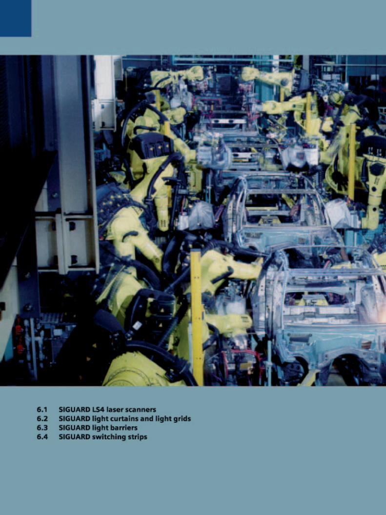
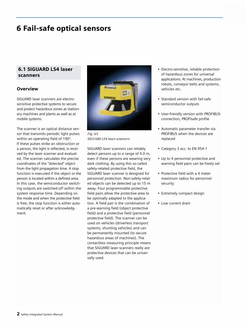
Overview
SIGUARD laser scanners are electro-sensitive protective systems to secureand protect hazardous zones at station-ary machines and plants as well as atmobile systems.
The scanner is an optical distance sen-sor that transmits periodic light pulseswithin an operating field of 190°. If these pulses strike an obstruction or a person, the light is reflected, is recei-ved by the laser scanner and evaluat-ed. The scanner calculates the precisecoordinates of the “detected” objectfrom the light propagation time. A stopfunction is executed if the object or theperson is located within a defined area.In this case, the semiconductor switch-ing outputs are switched-off within thesystem response time. Depending onthe mode and when the protective fieldis free, the stop function is either auto-matically reset or after acknowledg-ment.
SIGUARD laser scanners can reliablydetect persons up to a range of 4.0 m,even if these persons are wearing verydark clothing. By using this so-calledsafety-related protective field, theSIGUARD laser scanner is designed forpersonnel protection. Non-safety-relat-ed objects can be detected up to 15 maway. Four programmable protectivefield pairs allow the protective area tobe optimally adapted to the applica-tion. A field pair is the combination ofa pre-warning field (object protectivefield) and a protective field (personnelprotective field). The scanner can beused on vehicles (driverless transportsystems, shunting vehicles) and can be permanently mounted (to securehazardous areas of machines). Thecontactless measuring principle meansthat SIGUARD laser scanners really areprotective devices that can be univer-sally used.
• Electro-sensitive, reliable protection of hazardous zones for universal applications: At machines, production robots, conveyor belts and systems, vehicles etc.
• Standard version with fail-safesemiconductor outputs
• User-friendly version with PROFIBUS-connection, PROFIsafe profile
• Automatic parameter transfer via PROFIBUS when the devices are replaced
• Category 3 acc. to EN 954-1
• Up to 4 personnel protective and warning field pairs can be freely set
• Protective field with a 4 metermaximum radius for personnel security
• Extremely compact design
• Low current drain
2 Safety Integrated System Manual
6.1 SIGUARD LS4 laserscanners
Fig. 6/1
SIGUARD LS4 laser scanners
6 Fail-safe optical sensors

Protecting stationary hazardousareas
In modern production plants and sys-tems, personnel must frequently enterpotentially dangerous zones and areas.While personnel are in such dangerousareas, it must be absolutely guaranteedthat the machine or plant does not re-present any danger. However, the safe-ty measures required should, as far aspossible, not have a negative impacton production operations.
SIGUARD laser scanners allow dangerousareas and zones to be secured - flexiblyand contactlessly.
Protecting horizontal dangerousareas
• Safely detecting persons and objects in dangerous areas of machines and plants
• Flexible programming, essentially any protective and warning fields can be set-up
Protecting horizontal dangerousareas with several protective fields
• Safely detecting persons in different dangerous areas by toggling betweenprotective fields
• Increased availability by specificallysecuring only those areas that are presently active
Securing driverless transport vehicles - mobile applications
Our SIGUARD LS4-4 laser scanner canbe used on driverless transport vehi-cles to monitor the route. Persons andobjects are detected and the vehicle isautomatically brought to a standstillwhen necessary. Previous protective
systems such as bumpers, protectivebars etc. only permit a low vehiclevelocity. A significantly higher safetyarea is obtained with the SIGUARD LS4-4 laser scanner as contactless “leadingbumper”. This means that vehicles canoperate faster and stopping times arereduced to the necessary minimum.
Monitoring routes of driverlesstransport systems
• Persons and objects that approach the vehicle aresafely protected
• When compared to bumpers orprotective bars, laser scanners offer a wider safety area therefore permit-ting higher speeds
Collision protection for vehicles
• Persons along the route are reliably protected
• Objects along the route are detected in plenty of time therefore avoiding damage to the vehicle and the mate-rial it is carrying
Safety Integrated System Manual 3
6
Fig. 6/2
Stationary danger zone protection
Fig. 6/3
Horizontal danger zone protection
Fig. 6/4
Fig. 6/5

SIGUARD LS4 laser scanners are avail-able in three different versions. Theappropriate version can be selecteddepending on whether the scanner isto be electrically integrated in the safe-ty circuit. There is no difference in thevarious units as far as their function isconcerned as laser scanner to securedangerous areas.
In the standard version, the scannerhas two fail-safe self-monitoring semi-conductor outputs that allow it to beintegrated into conventional circuits.
The bus versions for ASIsafe allow thefail-safe direct connection to ASIsafe.
The safety-related shutdown is real-ized, in this case via the AS-Interfacesafety monitor.
The second bus-capable version con-nects the laser scanner to PROFIBUS.The non-proprietary PROFIsafe profileis used to exchange data in both direc-tions in a fail-safe way. Both the safety-related shutdown signal as well as alsothe protective field changeover can betransferred via the bus, controlled fromthe fail-safe PLC.
There is a range of accessories for theSIGUARD laser scanners. These includemounting brackets, software as well asconnecting and programming cables.
Individual details regarding the acces-sories as well as additional SIGUARDlaser scanner documents are providedin the Internet under:http://www.siemens.de/fas
4 Safety Integrated System Manual
6 – Fail-safe optical sensors
Fail-safe semiconductor outputs 3RG7834-6DD00incl. LS4soft software
Fail-safe direct connection 3SF7834-6DD00to ASIsafeincl. LS4soft software
Fail-safe direct connection 3SF7834-6PB00to PROFIBUSIncl. LS4soft software
SIGUARD LS4-4 laser scanners, standard version
SIGUARD LS4-4 laser scanner, ASIsafe
SIGUARD LS4-4 laser scanner, PROFIsafe
Fig. 6/6
Product families/product groups

Design
SIGUARD LS4 laser scanners are optical,electro-sensitive area scanners thathave been mainly designed for the pro-tection of personnel. The laser scannercontinuously generates periodic lightpulses, generated using a laser diodewith the appropriate optical system.These light pulses are distributed overthe complete operating area using anintegrated rotating mirror. If persons orobjects enter the field, then the scan-ner evaluates the reflected light pulses,and using the propagation time of thelight pulses, precisely and continuallycalculates the precise position coordi-nates. If the defined personnel protec-tive field is violated, it outputs a shut-down signal to immediately shut downthe machine itself.
The operating range of the SIGUARDLS4 laser scanner is 190° and is subdi-vided into angular segments of 0.36°degrees. The scan rate is 25 scans persecond. This means a light pulse inevery segment every 40 ms. A specialalgorithm ensures that objects from asize of 70 mm onwards – this corre-sponds to the scanner resolution – arereliably detected. However, it is ensuredthat ambient effects – such as dust –do not have a negative impact on theavailability of the plant or system.
SIGUARD LS4 laser scanners reliablydetect persons – even if they are wear-ing dark clothing – safety-related up to4 meters away. Persons and objectscan be detected up to a distance of 15meters away and an alarm messagecan be output (at this distance, it is not safety-related).
Safety Integrated System Manual 5
6
Fig. 6/7 Mode of operation
Fig. 6/8Angular resolution
Fig. 6/9Protective warning fields
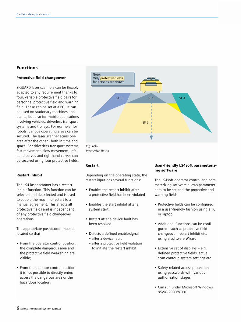
Functions
Protective field changeover
SIGUARD laser scanners can be flexiblyadapted to any requirement thanks tofour, variable protective field pairs forpersonnel protective field and warningfield. These can be set at a PC. It canbe used on stationary machines andplants, but also for mobile applicationsinvolving vehicles, driverless transportsystems and trolleys. For example, forrobots, various operating areas can besecured. The laser scanner scans onearea after the other - both in time andspace. For driverless transport systems,fast movement, slow movement, left-hand curves and righthand curves canbe secured using four protective fields.
Restart inhibit
The LS4 laser scanner has a restartinhibit function. This function can beselected and de-selected and is used to couple the machine restart to amanual agreement. This affects all protective fields and is independent of any protective field changeoveroperations.
The appropriate pushbutton must belocated so that
• From the operator control position, the complete dangerous area and the protective field weakening are visible;
• From the operator control position it is not possible to directly enter/access the dangerous area or the hazardous location.
Restart
Depending on the operating state, therestart input has several functions:
• Enables the restart inhibit aftera protective field has been violated
• Enables the start inhibit after a system start
• Restart after a device fault hasbeen resolved
• Detects a defined enable signal• after a device fault• after a protective field violation
to initiate the restart inhibit
User-friendly LS4soft parameteriz-ing software
The LS4soft operator control and para-meterizing software allows parameterdata to be set and the protective andwarning fields.
• Protective fields can be configuredin a user-friendly fashion using a PC or laptop
• Additional functions can be confi-gured - such as protective field changeover, restart inhibit etc. using a software Wizard
• Extensive set of displays – e.g. defined protective fields, actualscan contour, system settings etc.
• Safety-related access protection using passwords with various authorization stages
• Can run under Microsoft Windows 95/98/2000/NT/XP
6 Safety Integrated System Manual
6 – Fail-safe optical sensors
Fig. 6/10
Protective fields

Integration into the system
Depending on the requirements andtype of safety system that the user hasselected, safety sensors can be con-nected in various ways to the safetycircuit of the particular machine orplant.
The basic ways of connecting varioussensors is described in Chapter 3. Here, SIGUARD laser scanners offerevery possibility. In addition to favor-ably-priced, conventional connectionthrough fail-safe semiconductor out-puts, the bus-capable versions allowlaser scanners to be incorporated intoSiemens automation solutions in asafety-related fashion using standardbus systems AS-Interface and PROFIBUS.
Safety Integrated System Manual 7
6
Fig. 6/11
LS4Soft software
Fig. 6/12
Integration into the overall system

Application information
SIGUARD laser scanners are optical,electro-sensitive protective systems.Conditions relating to their correct use must be carefully observed whenusing these devices.
Some of the most essential issues arelisted below:
General information:
• SIGUARD LS4-4 laser scanners shouldbe mounted so that the-protectivefield completely covers the access to the dangerous area to be monitored.
• The scanner mounting position mustbe protected against moisture, dirt, as well as temperatures below 0°C or above 50°C.
• The mounting location should be selected so that the danger ofmechanical damage is minimized. Additional protective covers or bars must be provided at exposed loca-tions.
• Protective covers, panels, mounting niches and other machine-related elements may not have a negative impact on the scanner field.
• If areas are located in the scanner field of operation that cannot be scanned - as a result of permanent obstructions, that were defined as protective field limit, then these should be secured (e.g. using protec-tive gates), so that persons in these areas that cannot be detected, can-not suddenly enter the protective field. When carrying-out a hazardousanalysis of the machine or plant, thispoint must be carefully taken into account.
• Retro-reflectors or very bright sur-faces, such as certain metals or ceramics, close to the protectivefield and at the scanner level heightshould be avoided as these can cause measuring faults and errors.
• In order to secure a consistentdetection height at every point in the-protective field, the scanner– and therefore the beam level should be mounted parallel to the reference plane.
• If the “restart inhibit” function is activated, the restart button must be located outside the protective field at a location where the com-plete hazardous area is clearly visible and can be seen.
Information regarding protectivefield changeover:
In order to achieve optimum machineutilization, often, alternating loading/machining cycles are implemented thatresults in changing hazardous areas.Also driverless transport vehicles, fromtheir very nature, include various haz-ardous zones. If it can be expected thatpersons enter these areas, then it isabsolutely necessary to provide anappropriate safety system. Our SIGUARDLS4 laser scanner fulfills many require-ments regarding securing the widestrange of applications thanks to its fourfreely-configurable protective and alarmfields that can be changed over (fieldpairs).
The user-friendly “LS4soft” operatorprogram can be used to define thenecessary field pair contours.
The field pairs are activated by con-necting 24 V at the appropriate inputs.
8 Safety Integrated System Manual
6 – Fail-safe optical sensors

If the SIGUARD LS4-4 laser scanner isto be restarted or it is necessary to tog-gle between various field pairs, thenthe following points must be carefullyobserved:
• The field pair intended for the start, must be defined, taking into special account the dangerous areas valid atthis time.
• The second field pair should first be switched-in, and then the first field pair switched-out.
• The changeover must take placewithin 1 s.
• At no time, may the changeoversequence include de-activating allfield pairs.
• With the exception of the changeoveroperation, only one field pair may beactive at any one time.
• The sequence of the monitoringfields to be activated must ensure that at no time the application-re-lated minimum protective field size is fallen below.
• Changeover signals may neverchange simultaneously due to asystematic fault. This is achieved by using independent circuits (e.g. separately actuated binary switches), taking into account the switching behavior described above.
Calculating the protectivefield
When using electro-sensitive opticalprotective systems such as laser scan-ners, it must always be ensured thatany potentially hazardous machinemotion is stopped before people areinjured. This is the reason, for exam-ple, that the laser scanner must moni-tor a protective field that is largeenough that after a dangerous area isentered, then there is enough time toinitiate a machine stop.
Securing stationary dangerousareas
The following calculations must beused as basis when using a laser scan-ner to secure static dangerous areas.
In order to calculate the safety clear-ance and the minimum protective fielddepth, the following relationships applyin compliance with IEC 61496-3 andDIN EN 999 when approaching parallelto the protective field:
Safety clearance
S = (K x T) + C
C = 1200 mm – 0.4 H
CMIN = 850 mmHMIN = 15 (d – 50 mm)HMAX = 1000 mm
S = Safety clearance, minimumclearance from the dangerousarea to the detection point,to the detection plane or to theprotective field in mm
K = Approach velocity of a personor his body parts in mm/s (1600 mm/s)
T = Run-on time of the total system (response and braking times down to standstill) in s
C = Safety-related constant in mm to take into account interven-tion/penetration into the dangerous area before the protective device responds
CMIN = Minimum value of the safety-related constant in mm (850 mm)
H = Height of the measured value detection plane from thereference point in mm
HMIN = Minimum height of the mea-sured value detection plane from the reference plane in mm
HMAX = Maximum height of the measured value detection planefrom the reference plane in mm
d = Scanner resolution in mm (70 mm, protective field width)
Safety Integrated System Manual 9
6
Fig. 6/13
Securing stationary dangerous areas
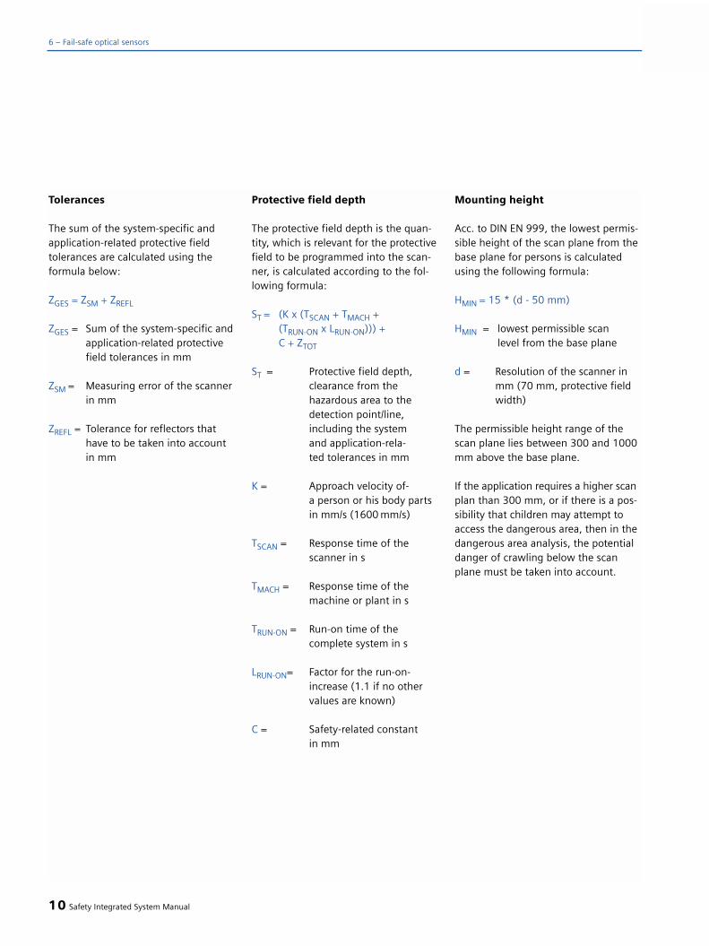
Tolerances
The sum of the system-specific andapplication-related protective fieldtolerances are calculated using theformula below:
ZGES = ZSM + ZREFL
ZGES = Sum of the system-specific andapplication-related protective field tolerances in mm
ZSM = Measuring error of the scannerin mm
ZREFL = Tolerance for reflectors that have to be taken into account in mm
Protective field depth
The protective field depth is the quan-tity, which is relevant for the protectivefield to be programmed into the scan-ner, is calculated according to the fol-lowing formula:
ST = (K x (TSCAN + TMACH + (TRUN-ON x LRUN-ON))) + C + ZTOT
ST = Protective field depth, clearance from the hazardous area to the detection point/line, including the system and application-rela-ted tolerances in mm
K = Approach velocity of-a person or his body parts in mm/s (1600 mm/s)
TSCAN = Response time of the scanner in s
TMACH = Response time of the machine or plant in s
TRUN-ON = Run-on time of the complete system in s
LRUN-ON= Factor for the run-on-increase (1.1 if no othervalues are known)
C = Safety-related constantin mm
Mounting height
Acc. to DIN EN 999, the lowest permis-sible height of the scan plane from thebase plane for persons is calculatedusing the following formula:
HMIN = 15 * (d - 50 mm)
HMIN = lowest permissible scanlevel from the base plane
d = Resolution of the scanner in mm (70 mm, protective field width)
The permissible height range of thescan plane lies between 300 and 1000mm above the base plane.
If the application requires a higher scanplan than 300 mm, or if there is a pos-sibility that children may attempt toaccess the dangerous area, then in thedangerous area analysis, the potentialdanger of crawling below the scanplane must be taken into account.
10 Safety Integrated System Manual
6 – Fail-safe optical sensors

Protecting driverless transportvehicles - mobile applications
The following essential conditions mustbe carefully observed when using theSIGUARD laser scanner to protect dri-verless transport systems - i.e. mobileapplications.
Safety clearance
When calculating the safety clearance,the following relationships applyaccording to IEC 61496-3:
S = (VMAXFTS x T) + SANHALT
VMAXFTS = Maximum velocity of the driverless vehicle in mm/s
T = Response time of the scannerand the driverless vehicle in s
SANHALT = Stopping distance of the driverless vehicle down to standstill in mm
Protective field depth
The depth of the protective field in thedirection of travel, referred to the dis-tance between the limit of the vehicleand the protective field limiting line iscalculated according to the followingformula:
ST = VMAXFTS x (TSCAN + TFTS) + (SANHALT x LANHALT) + ZGES
ST = Protective field depth inthe direction of travel in mm
VMAXFTS = Maximum velocity of the driverless vehicle in mm/s
TSCAN = Response time of the scanner in s
TFTS = Response time of the driverless vehicle in s
LANHALT = Factor for brake wear (1.1 if no other values are known)
ZGES = Sum of the system-specificand application relatedtolerances in mm
Tolerances
ZGES = ZSM + ZREFL + ZAFUSS + ZAU
ZSM = Scanner measuring error in mm
ZREFL = Tolerance in mm for thereflectors to be taken into account
ZAFUSS = Tolerance in mm for the driverless vehicle and the
floor
ZAU = Application-relevant tolerancein mm (e.g. under-cuts)
Mounting height
The mounting height should always be kept as low as possible in order toprevent somebody crawling below the protective field. This parameter isrestricted by e.g. unevenness in thefloor surface and the spring travel ofthe driverless vehicle.
The maximum mounting height shouldbe selected so that an object (horizon-tal cylinder with a 200 mm diameter)is reliably detected (refer to DIN EN1525). This should be checked at themaximum protective field depth.Regarding adequate detection resolu-tion, for a driverless vehicle applica-tion, an object (upright cylinder) witha diameter of 70 mm, protective fieldwidth, is sufficient.
The examples described here providethe basic principles when it comes tocalculating protective fields. Moredetailed information and calculationexample are provided in the TechnicalInstructions of the SIGUARD laser scan-ners in the Internet under: http://www.siemens.de/fas
Safety Integrated System Manual 11
6
Fig. 6/14
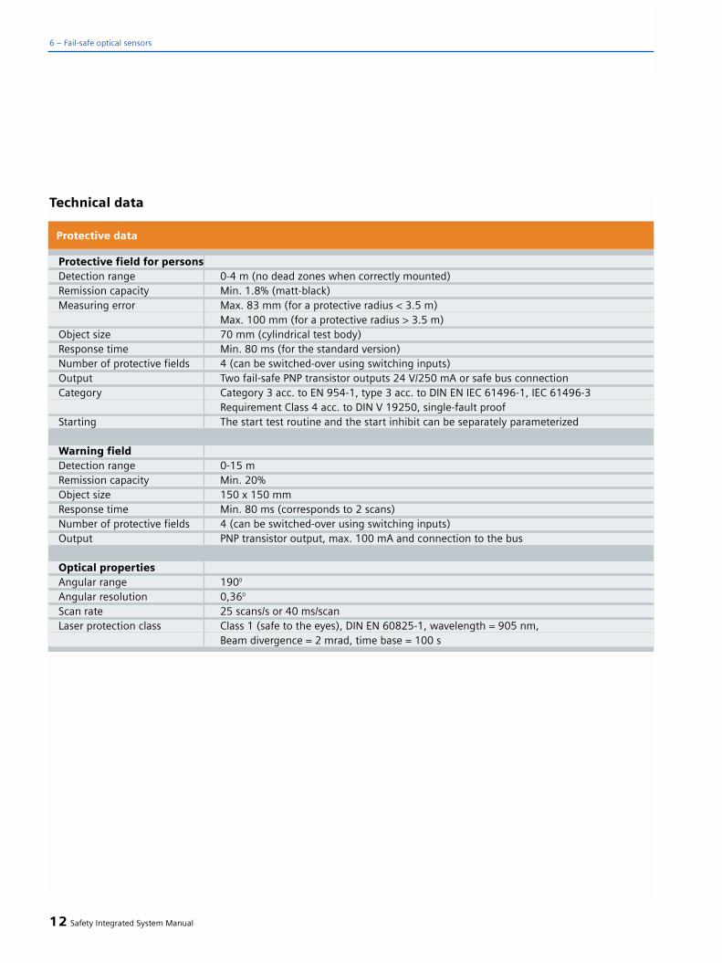
Technical data
((Change technical data:
Measuring error: “max. 83 mm” insteadof “max. 81 mm” and “max. 100 mm”instead of “max. 98 mm”
12 Safety Integrated System Manual
Protective field for personsDetection range 0-4 m (no dead zones when correctly mounted)Remission capacity Min. 1.8% (matt-black)Measuring error Max. 83 mm (for a protective radius < 3.5 m)
Max. 100 mm (for a protective radius > 3.5 m)Object size 70 mm (cylindrical test body)Response time Min. 80 ms (for the standard version)Number of protective fields 4 (can be switched-over using switching inputs)Output Two fail-safe PNP transistor outputs 24 V/250 mA or safe bus connectionCategory Category 3 acc. to EN 954-1, type 3 acc. to DIN EN IEC 61496-1, IEC 61496-3
Requirement Class 4 acc. to DIN V 19250, single-fault proofStarting The start test routine and the start inhibit can be separately parameterized
Warning fieldDetection range 0-15 m Remission capacity Min. 20% Object size 150 x 150 mmResponse time Min. 80 ms (corresponds to 2 scans)Number of protective fields 4 (can be switched-over using switching inputs)Output PNP transistor output, max. 100 mA and connection to the bus
Optical propertiesAngular range 1900
Angular resolution 0,360
Scan rate 25 scans/s or 40 ms/scanLaser protection class Class 1 (safe to the eyes), DIN EN 60825-1, wavelength = 905 nm,
Beam divergence = 2 mrad, time base = 100 s
Protective data
6 – Fail-safe optical sensors
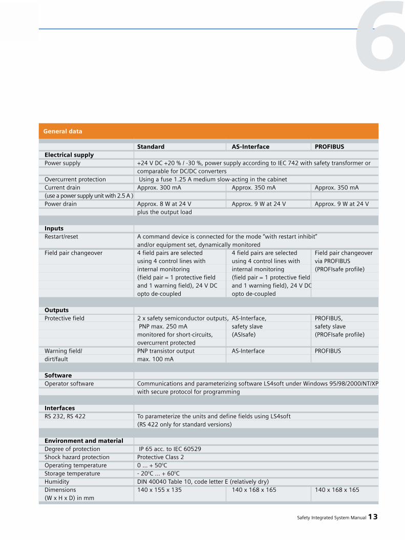
Safety Integrated System Manual 13
General data
Standard AS-Interface PROFIBUSElectrical supplyPower supply +24 V DC +20 % / -30 %, power supply according to IEC 742 with safety transformer or
comparable for DC/DC convertersOvercurrent protection Using a fuse 1.25 A medium slow-acting in the cabinetCurrent drain Approx. 300 mA Approx. 350 mA Approx. 350 mA(use a power supply unit with 2.5 A )Power drain Approx. 8 W at 24 V Approx. 9 W at 24 V Approx. 9 W at 24 V
plus the output load
InputsRestart/reset A command device is connected for the mode “with restart inhibit”
and/or equipment set, dynamically monitoredField pair changeover 4 field pairs are selected 4 field pairs are selected Field pair changeover
using 4 control lines with using 4 control lines with via PROFIBUSinternal monitoring internal monitoring (PROFIsafe profile)(field pair = 1 protective field (field pair = 1 protective fieldand 1 warning field), 24 V DC and 1 warning field), 24 V DCopto de-coupled opto de-coupled
OutputsProtective field 2 x safety semiconductor outputs, AS-Interface, PROFIBUS,
PNP max. 250 mA safety slave safety slavemonitored for short-circuits, (ASIsafe) (PROFIsafe profile)overcurrent protected
Warning field/ PNP transistor output AS-Interface PROFIBUSdirt/fault max. 100 mA
SoftwareOperator software Communications and parameterizing software LS4soft under Windows 95/98/2000/NT/XP
with secure protocol for programming
InterfacesRS 232, RS 422 To parameterize the units and define fields using LS4soft
(RS 422 only for standard versions)
Environment and materialDegree of protection IP 65 acc. to IEC 60529Shock hazard protection Protective Class 2Operating temperature 0 ... + 500CStorage temperature - 200C ... + 600CHumidity DIN 40040 Table 10, code letter E (relatively dry)Dimensions 140 x 155 x 135 140 x 168 x 165 140 x 168 x 165(W x H x D) in mm
6

14 Safety Integrated System Manual
6 – Fail-safe optical sensors
Relevant Standards
• EN 61 496-1, -2, IEC 61 496-1, -2 (requirements for contactlessprotective systems)
• EN 999 (e.g. calculating safety clearances)
• EN 954-1 (safety of machinerysafety related parts of controls)
SIGUARD light curtains and lightgrids
• Are active opto-electronic protective devices (AOPD)
• Correspond to type 2 (3RG78 41) or type 4 (3RG78 42/4) acc. toEN 61496-1, -2
• Are EC-prototype tested
• Protect operating personnel at or close to hazardous machines
• Operate contactlessly
• Are wear-free when compared to mech. systems (e.g. contact mats)
The prerequisites are as follows:
• Correctly mounted and installed• Correctly connected to the machine
control
Information is provided in this sectionand in the Instruction Manuals provid-ed with the particular devices.
Tests/Service
The devices are EC type tested (TÜV[German Technical Inspectorate]Product Service in conjunction with the Institute for Health and Safety atWork - BGIA).
Configuration
• Using teach-in with opto-magnetickey
• Configuration data is transferredusing a plug-in configuration card
Features
SIGUARD light curtains, grids andtransceivers 3RG7844/ 3SF7844with integrated evaluation for category 4 acc. to EN 954-1
• Resolution 14, 30 and 50 mmProtective field heights of150 to 3 000 mmranges 0.3 to 6 m or 0.8 to 18 m.
• 2, 3 or 4-beam light grids beam clearance 500, 400 and 300 mmranges 0.8 to 18 m or 6 to 70 m
• 2-beam transceiver beam clearance 500 mmrange 0.8 to 6 m
• Host and guest devices can becascaded for higher protectivefield heights and lengths or forangled arrangements
Integrated functions:
Standard function package• Start/restart inhibit• Contact monitoring• Multi-scan
Blanking function package• Functions of the standard function
package and additionally• Fixed blanking• Floating blanking• Reduced resolution
Fig. 6/15
SIGUARD light curtains, light grids and
evaluation units
6.2 SIGUARD light curtains and light grids

Muting function package• Functions of the standard function
package and additionally• 4-sensor, sequential muting• 2-sensor, parallel muting• 3-sensor, direction muting• 4-sensor, parallel muting
Cycle control function package• Functions of the standard function
package and additionally• Cycle control using 1-clock and
2-clock cycle operation
Configuration:
• Using teach-in with opto-magnetic key
• Configuration data is transferredusing a plug-in configuration card
• 2 data transfer channels• Host and guest devices can be
cascaded• Extended display (2x7 segments)
Outputs/connections available forevery function package
• Local interface to connect additional safety sensors
• Transistor outputs with cable gland or Brad-Harrison-connectors
• Relay outputs with Hirschmannconnectors
• Connection to ASIsafe
SIGUARD 3RG7842/3SF7842 lightcurtains, grids for Category 4 acc.to EN 954-1
• Resolution 14, 30, 50 and 90 mmProtective field heights from 150 to 3 000 mmRanges 0.3 to 6 m or 0.8 to 18 m
• 2, 3 or 4-beam light grids,beam clearance 500, 400 and 300 mmRanges 0.8 to 18 m or 6 to 70 m
• Host and guest devices can becascaded for higher protective fieldheights or lengths and for angledarrangements
SIGUARD 3RG7841 light curtainsfor Category 2 acc. EN 954-1
• Resolution 30, 55 and 80 mmprotective field heights of 150 to 1 800 mmRanges 0.3 to 6 m
• Host and guest devices can becascaded for higher protective fieldheights or lengths and for angled arrangements
SIGUARD 3RG7825/47 evaluationunits for Category 2 and 4 acc. toEN 954-1
• These are used to connect thesafety-related signals of light curtains, light grids, light barriers and transceivers in the machine control.
• Start/restart inhibit
• Contactor monitoring
• Muting
• Cycle control
• Predictive failure alarm for the relay contacts
• Diagnostic function using PC
• Numerous signaling outputs to ahigher-level control
Safety Integrated System Manual 15
6
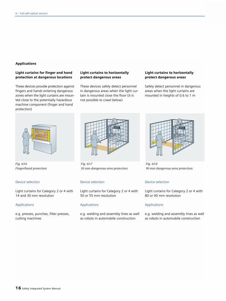
Applications
Light curtains for finger and handprotection at dangerous locations
These devices provide protection againstfingers and hands entering dangerouszones when the light curtains are moun-ted close to the potentially hazardousmachine component (finger and handprotection)
Device selection
Light curtains for Category 2 or 4 with14 and 30 mm resolution
Applications
e.g. presses, punches, filter presses,cutting machines
Light curtains to horizontallyprotect dangerous areas
These devices safely detect personnelin dangerous areas when the light cur-tain is mounted close the floor (it isnot possible to crawl below)
Device selection
Light curtains for Category 2 or 4 with50 or 55 mm resolution
Applications
e.g. welding and assembly lines as wellas robots in automobile construction
Light curtains to horizontallyprotect dangerous areas
Safely detect personnel in dangerousareas when the light curtains aremounted in heights of 0.6 to 1 m
Device selection
Light curtains for Category 2 or 4 with80 or 90 mm resolution
Applications
e.g. welding and assembly lines as wellas robots in automobile construction
16 Safety Integrated System Manual
6 – Fail-safe optical sensors
Fig. 6/16
Finger/hand protection
Fig. 6/17
50 mm dangerous area protection
Fig. 6/18
90 mm dangerous area protection
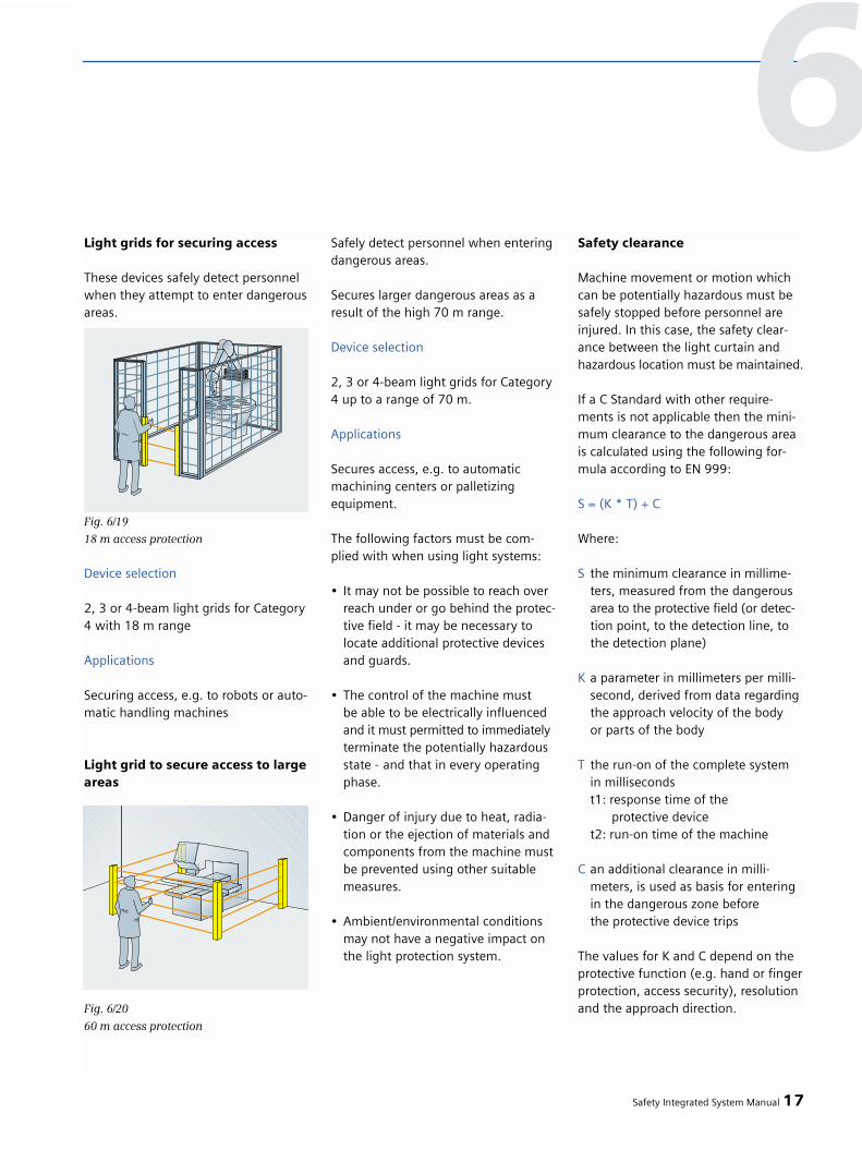
Safety Integrated System Manual 17
Light grids for securing access
These devices safely detect personnelwhen they attempt to enter dangerousareas.
Device selection
2, 3 or 4-beam light grids for Category4 with 18 m range
Applications
Securing access, e.g. to robots or auto-matic handling machines
Light grid to secure access to largeareas
Safely detect personnel when enteringdangerous areas.
Secures larger dangerous areas as aresult of the high 70 m range.
Device selection
2, 3 or 4-beam light grids for Category4 up to a range of 70 m.
Applications
Secures access, e.g. to automaticmachining centers or palletizing equipment.
The following factors must be com-plied with when using light systems:
• It may not be possible to reach overreach under or go behind the protec-tive field - it may be necessary tolocate additional protective devices and guards.
• The control of the machine mustbe able to be electrically influenced and it must permitted to immediatelyterminate the potentially hazardous state - and that in every operating phase.
• Danger of injury due to heat, radia-tion or the ejection of materials and components from the machine must be prevented using other suitable measures.
• Ambient/environmental conditionsmay not have a negative impact on the light protection system.
Safety clearance
Machine movement or motion whichcan be potentially hazardous must besafely stopped before personnel areinjured. In this case, the safety clear-ance between the light curtain andhazardous location must be maintained.
If a C Standard with other require-ments is not applicable then the mini-mum clearance to the dangerous areais calculated using the following for-mula according to EN 999:
S = (K * T) + C
Where:
S the minimum clearance in millime-ters, measured from the dangerousarea to the protective field (or detec-tion point, to the detection line, to the detection plane)
K a parameter in millimeters per milli-second, derived from data regardingthe approach velocity of the bodyor parts of the body
T the run-on of the complete systemin millisecondst1: response time of the
protective devicet2: run-on time of the machine
C an additional clearance in milli-meters, is used as basis for entering in the dangerous zone beforethe protective device trips
The values for K and C depend on theprotective function (e.g. hand or fingerprotection, access security), resolutionand the approach direction.
Fig. 6/19
18 m access protection
Fig. 6/20
60 m access protection
6

Light curtain in a vertical arrange-ment in (max. 40 mm)
It may not be possible to reach around,reach over or reach under the protec-tive field. This can be implementedusing additional mechanical meshes/gates or by cascading the host andguest light curtains.
The minimum safety clearanceS is calculated according to
S = (K * T) + C
With
K = 2 mm/msC = 8 (d-14 mm),
however, not less than 0.
Whereby
d = resolution of the light curtainin mm.
If the calculation results in a value lessthan 100 mm, then under all circum-stances, a minimum clearance of 100mm must be maintained.
If the calculation results in a valuegreater than 500 mm, then this can be repeated with K=1.6 mm/ms. Underall circumstances, a minimum clear-ance of 500 mm must be maintained.
If the clearance between the lightcurtain and the machine is greaterthan 75 mm, then protection must be provided against reaching around(e.g. using a horizontally arrangedlight curtain).
Light curtain in a vertical arrange-ment (resolution 40 mm _< 70 mm)
The minimum safety clearance S iscalculated as follows
S = (K * T) + C
With
K = 1.6 mm/ms
C = 850 mm
Multi-beam light grids in a verticalarrangement for access security
It may not be possible to reach around,reach over or reach under the protec-tive field. This can be implementedusing additional mechanical gates orby cascading the host and guest lightcurtains.
The number and distance between thelight beams depends on the risk evalu-ation and on the machine-specific reg-ulations.
The minimum safety clearance is calcu-lated as follows according to EN 999:
S = (K * T) + C
With
K = 1.6 mm/ms
C = 850 mm
18 Safety Integrated System Manual
6 – Fail-safe optical sensors
Fig. 6/21
Fig. 6/22
4 300, 600, 900, 12003 300, 700, 11002 400, 900
Number of beams and heightabove the reference plane in mm

Light curtains in a horizontalarrangement to secure dangerousareas
When securing dangerous areas usinghorizontally mounted light curtains,the height H of the protective fieldmay be a maximum of 1000 mm. If His greater than 300 mm (200 mm ifchildren are present), then it is possi-ble to crawl below the protective field.This must be taken into account whenaccessing the risk.
The lowest permissible mounting heightdepends on the resolution of the lightcurtain in order to ensure that thehuman leg or joint in the foot can besafety detected.
S = (K * T) + C
K = 1.6 mm/ms
C = (1200 mm – 0.4 x H)
Where:
H = Height of the protective field above the reference plane
Hmax = 1000 mm
Hmin = 15 (d – 50 mm)
d = Resolution of the light curtain
If the calculation for C results in a lower value than 850 mm, then a minimum value of C = 850 mm should be assumed.
General description
A SIGUARD light curtain or light gridcomprises a sender and a receiver thatare mounted opposite to one another.Depending on the resolution and length,a specific number of transmitting andreceiving diodes are located one abovethe other. The infrared LEDs of the trans-mitter send short light pulses that arereceived by the associated receiverdiodes.
The transmitter and receiver are syn-chronized with one another opticallywithout requiring a direct electricalconnection.
Depending on the application, lightcurtains are required with various reso-lutions.
The resolution (detection capability) of a safety light curtain is that size ofobstruction that will be safely detectedat every position in the protective fieldand thus result in a shutdown com-mand.
The transceiver comprises a sender(transmitter) and a receiver in onedevice (transceiver). The infrared lightfrom the transmitter diode is reflectedtwice through 90° using a mirror andtherefore returns to the receiver diodeof the transceiver. This therefore cre-ates a two-beam light grid - that ismore favorable than a conventionallight grid with separate sender andreceiver. The device has five-pin M12sockets at the front panel. Muting sen-sors can be directly connected to this.
Safety Integrated System Manual 19
Fig. 6/23
Fig. 6/24
Transceiver principle
Fig. 6/25
Transceiver
6
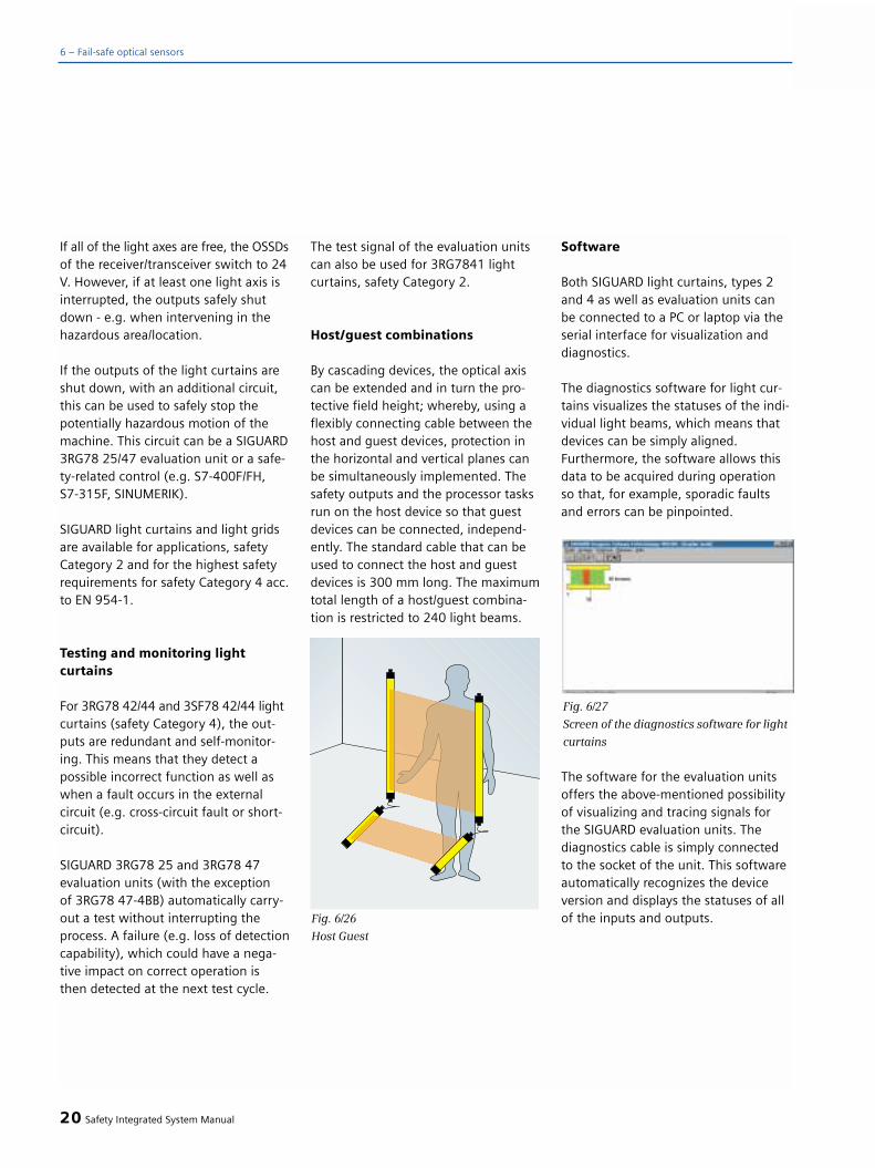
If all of the light axes are free, the OSSDsof the receiver/transceiver switch to 24V. However, if at least one light axis isinterrupted, the outputs safely shutdown - e.g. when intervening in thehazardous area/location.
If the outputs of the light curtains areshut down, with an additional circuit,this can be used to safely stop thepotentially hazardous motion of themachine. This circuit can be a SIGUARD3RG78 25/47 evaluation unit or a safe-ty-related control (e.g. S7-400F/FH, S7-315F, SINUMERIK).
SIGUARD light curtains and light gridsare available for applications, safetyCategory 2 and for the highest safetyrequirements for safety Category 4 acc.to EN 954-1.
Testing and monitoring lightcurtains
For 3RG78 42/44 and 3SF78 42/44 lightcurtains (safety Category 4), the out-puts are redundant and self-monitor-ing. This means that they detect apossible incorrect function as well aswhen a fault occurs in the externalcircuit (e.g. cross-circuit fault or short-circuit).
SIGUARD 3RG78 25 and 3RG78 47evaluation units (with the exception of 3RG78 47-4BB) automatically carry-out a test without interrupting theprocess. A failure (e.g. loss of detectioncapability), which could have a nega-tive impact on correct operation isthen detected at the next test cycle.
The test signal of the evaluation unitscan also be used for 3RG7841 lightcurtains, safety Category 2.
Host/guest combinations
By cascading devices, the optical axiscan be extended and in turn the pro-tective field height; whereby, using aflexibly connecting cable between thehost and guest devices, protection inthe horizontal and vertical planes canbe simultaneously implemented. Thesafety outputs and the processor tasksrun on the host device so that guestdevices can be connected, independ-ently. The standard cable that can beused to connect the host and guestdevices is 300 mm long. The maximumtotal length of a host/guest combina-tion is restricted to 240 light beams.
Software
Both SIGUARD light curtains, types 2and 4 as well as evaluation units canbe connected to a PC or laptop via theserial interface for visualization anddiagnostics.
The diagnostics software for light cur-tains visualizes the statuses of the indi-vidual light beams, which means thatdevices can be simply aligned.Furthermore, the software allows thisdata to be acquired during operationso that, for example, sporadic faultsand errors can be pinpointed.
The software for the evaluation unitsoffers the above-mentioned possibilityof visualizing and tracing signals forthe SIGUARD evaluation units. Thediagnostics cable is simply connectedto the socket of the unit. This softwareautomatically recognizes the deviceversion and displays the statuses of allof the inputs and outputs.
20 Safety Integrated System Manual
6 – Fail-safe optical sensors
Fig. 6/27
Screen of the diagnostics software for light
curtains
Fig. 6/26
Host Guest

Accessories
There is a range of accessories, opti-mized for use in the field that simplifymounting, alignment/adjustment,commissioning and troubleshooting.These include retaining columns,deflection mirror columns, deflectionmirrors, retaining brackets and laseralignment devices. The mountingcolumns and beam deflecting mirrorcolumns allow the light curtains, lightgrids and transceivers to be simplymounted to the floor. After the columnshave been bolted to the floor, a specialmechanical design allows the lightbeams to be precisely aligned.
This operation can be easily carried-outusing the laser alignment devices.
Connection versions
The light curtains, light grids andtransceivers are available in thefollowing connection versions:
• Transistor output with cable glandThe user routes the power supply cable through a cable gland located in the end cap of the devices and connects this to the screw terminals in the connection cap. For senders (transmitters), only the power supplyvoltage is fed in; receivers and trans-ceivers have in addition, the two safety switching outputs OSSD1 and OSSD2 as well as additional signal inputs and outputs.
• Relay outputs with HirschmannconnectionThe receiver/transceiver has 2 relay outputs and a connection for a Hirschmann connector in the end cap. The relay outputs with Hirsch-mann connection are suitable for switching protective extra low vol-tages up to 42 V AC/DC.
For the transistor version, the senderdoesn't have its own outputs, but has a Hirschmann connection to connect to the machine interface.The appropriate cable connectionsocket including the crimp contactsand the complete connecting cable -in various lengths - are availableas accessories in both straight or angled versions.
• Machine interface with ASIsafeconnectionA 3-pin M12 connector is providedin the end cap and a 5-pole M12
connector for the receiver/transceiver.These connectors are used to connectto the AS-Interface. A suitable coup-ling module is available as accessory so that the device can be connected with a 1:1 connection using a standardM12 extension cable. In order to save using a bus address, it is possible to combine a sender with cable gland or Hirschmann connector with a receiver with ASIsafe connection.
Functions
Functions packages for integratedevaluation
For SIGUARD 3RG7842 light curtainsand light grids, Category 4 as well asSIGUARD 3RG78 41 light curtains,Category 2, functions such as start/restart inhibit, contactor monitoringand muting are only possible in con-junction with an 3RG78 25 or 3RG7847evaluation unit.
SIGUARD 3RG7844 light curtains andlight grids, Category 4 represent a sup-plement to the existing product range,and are available in four function pack-ages, in which, the following functionsare integrated in the devices. This meansthat an evaluation unit is no longerrequired to implement these functions:
• Function package “Standard”: Start/restart inhibit, multi-scan, contactor monitoring, two data transfer channels as well as an optional 2-channel safetycircuit with contacts.
Safety Integrated System Manual 21
Fig. 6/28
Screen representation, diagnostics soft-
ware for evaluation units
6

• Function package “blanking”: This is just the same as the “standard”function package and in addition,the fixed blanking, floating blankingand reduced resolution functions
• Function package, “muting”: This is the same as the “standard” functionpackage and in addition the muting function in order to bypass the pro-tective device/equipment for a limitedtime as part of the correct functio-nality.
• Function package, cycle control: This is the same as the “Standard” function package and in addition,the cycle control function.This is intended not only to provide protection using the protective de-vice, but also control it in a safety-related fashion.
Increasing the noise immunitywith respect to strong externallight (multi-scan)
If disturbances are expected as a resultof strong external light under “noisy”ambient conditions - for instance -from stroboscope lamps or weldingrobots, it is often more favorable,when a beam is interrupted, to firstwait as to whether the interruptioncontinues, before the outputs are shutdown.
If the beam is no longer interrupted,then this could have been triggered by ambient conditions which wouldmean that it is not necessary to shutdown the plant or system.
If the beam remains interrupted, thenit must be assumed that there is apotential hazard and the plant or sys-tem is shut down. This increases theplant availability. However, the responsetime and therefore the safety clearanceis increased.
If the multi-scan mode is used, thereceiver and/or transceiver go into the OFF state for a defined number of consecutive scans as soon as thelight beams are interrupted.
Data transfer channels
SIGUARD 3RG784 and 3SF784 lightcurtains, light grids and transceiversare equipped with two different datatransfer channels. In order to differen-tiate between the transmitted infraredlight and the ambient light, and to avoidinfluence, e.g. from warning lights ofpassing forklift trucks or welding sparks,data is transferred in pulse packets.
If two protective fields of a machineare located directly next to one anoth-er and there is a danger that, for exam-ple, beams from sender 1 are receivedby receiver 2, two different data trans-fer channels can be selected. Thetransfer channels must be changedover both in the sender as well as inthe receiver so that the two appropri-ate devices recognize one another.
22 Safety Integrated System Manual
6 – Fail-safe optical sensors
Fig. 6/29
Multi-scan

Start/restart inhibit
In order to prevent that the plant orsystem immediately starts to run againafter a protective field was interruptedand then becomes free again, the start/restart inhibit function can be activat-ed. The receiver or the transceiver onlygo into the ON state if a start button ispressed and is then released again. The start button must be pressed andreleased within a time window of be-tween 0.1 and 4 seconds.
The start/restart inhibit is mandatoryfor access security, as only the entry tothe dangerous area is monitored, butnot the area between the protectivefield and the potentially hazardousmotion.
The command device to enable the start/restart inhibit must be mounted so thatthe
• dangerous area can be easily seen from the command device and this
• command device cannot be actuatedfrom the dangerous area
Contactor monitoring
The contactor monitoring function isused to monitor the contactors, relaysor valves downstream from the lightcurtain. In this case, switching ele-ments with positively-driven feedbackcontacts are mandatory.
For the dynamic contactor monitoringfunction, a check is made whether,after the enable, the feedback circuithas opened within 300 ms, and afterthe OSSD has shut down, re-closesagain within 300 ms. If this is not thecase, then the enable circuit returns tothe OFF state.
Blanking functions
There are three different blankingfunctions that can be selected depend-ing on the application:
• Fixed blanking to suppress fixed objects that do not move
• Floating blanking for moving objects that are always in the protective field
• Reduced resolution for moving objects in the protective field thatcan temporarily exit the protective field
Depending on the blanking type, thesystem is configured using teach-inand the safety keys or using the DIPswitch in the connection cap. It is nei-ther necessary to have a PC nor con-nect a PC to the programming inter-face.
Fixed blanking
The “fixed blanking” function can beused if stationary objects are perma-nently in the protective field of thelight curtain. If this function is notused, the light curtain would shutdown as not all of the beams trans-mitted by the sender would bereceived by the receiver.
Fixed blanking is possible at any loca-tion of the light curtain, whereby thenumber of blanked beams is unrestrict-ed. The first beam after the displayfield cannot be blanked as this involvesthe synchronizing beam between thesender and receiver.
Safety Integrated System Manual 23
Fig. 6/30
Data transfer channels
6

The light curtain permanently monitorsthe blanked object: The light curtainchecks whether the object is locatedprecisely at the position which wastaught-in. If the object is removed, thelight curtain shuts down the plant -otherwise a safety risk would be creat-ed as a result of the blanked light beam.
Floating blanking
The floating blanking function can beused if moving objects are continuallyin the light curtain area. For floatingblanking, several objects can be simul-taneously blanked. The number offloating beams that can be blanked is unlimited.
The object that is blanked, floating, is permanently monitored: The lightcurtain checks as to whether the object is permanently in the lightcurtain area.
Reduced resolution
If moving objects are not permanentlyin the protective field of the light cur-tain, the reduced resolution functioncan be used. Contrary to floating blank-ing, the object is not permanentlymonitored. This means that no beamhas to be interrupted, but, dependingon the beam reduction selected, sever-al beams can be interrupted.
The effective light curtain resolution ischanged when using the “reduced res-olution” function. The safety clearancemust be re-calculated using the effec-tive resolution.
24 Safety Integrated System Manual
6 – Fail-safe optical sensors
Fig. 6/31Fixed blanking
Fig. 6/32Floating blanking
Fig. 6/33Reduced resolution
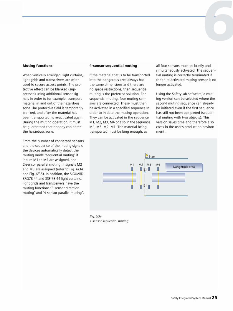
Muting functions
When vertically arranged, light curtains,light grids and transceivers are oftenused to secure access points. The pro-tective effect can be blanked (sup-pressed) using additional sensor sig-nals in order to for example, transportmaterial in and out of the hazardouszone.The protective field is temporarilyblanked, and after the material hasbeen transported, is re-activated again.During the muting operation, it mustbe guaranteed that nobody can enterthe hazardous zone.
From the number of connected sensorsand the sequence of the muting signalsthe devices automatically detect themuting mode “sequential muting” ifinputs M1 to M4 are assigned, and2-sensor parallel muting, if signals M2and M3 are assigned (refer to Fig. 6/34and Fig. 6/35). In addition, the SIGUARD3RG78 44 and 3SF 78 44 light curtains,light grids and transceivers have themuting functions “3-sensor directionmuting” and “4-sensor parallel muting”.
4-sensor sequential muting
If the material that is to be transportedinto the dangerous area always has the same dimensions and there are no space restrictions, then sequentialmuting is the preferred solution. Forsequential muting, four muting sen-sors are connected. These must thenbe activated in a specified sequence inorder to initiate the muting operation.They can be activated in the sequenceM1, M2, M3, M4 or also in the sequenceM4, M3, M2, M1. The material beingtransported must be long enough, as
all four sensors must be briefly andsimultaneously activated. The sequen-tial muting is correctly terminated ifthe third activated muting sensor is nolonger activated.
Using the SafetyLab software, a mut-ing version can be selected where thesecond muting sequence can alreadybe initiated even if the first sequencehas still not been completed (sequen-tial muting with two objects). Thisversion saves time and therefore alsocosts in the user's production environ-ment.
Safety Integrated System Manual 25
Fig. 6/34
4-sensor sequential muting
6

2-sensor parallel muting
Parallel muting is preferably used inthose plants and systems where thedimensions of the material to be trans-ported are not constant, or where spaceis somewhat restricted. Two muting sensors can be used, whosebeams cross behind the protective fieldin the hazardous area.
Parallel muting is initiated if the twoM2 and M3 signals switch simultane-ously without M1 and M4 either beingactivated or connected either before-hand or at the same time. 2-sensor parallel muting can be imple-mented at a low cost as only two mut-ing sensors are required - and it is pos-sible to move backwards and forwardswithin the muting distance.
3-sensor direction muting
3-sensor direction muting has a similardesign to the 2-sensor parallel muting.Material can only be transported throughthe light curtain in one direction. In order to initiate the muting function,to start, muting sensor M1 must beactivated, followed by the two mutingsensors M2 and M3. If the paths ofmuting sensors M2 and M3 are inter-rupted, it is no longer necessary toactivate sensor M1.
26 Safety Integrated System Manual
6 – Fail-safe optical sensors
Fig. 6/352-sensor parallel muting
Fig. 6/363-sensor direction muting

4-sensor parallel muting
If the material to be transported is toosmall to be simultaneously protectedby 4 sequentially arranged sensors, andif the space is extremely restricted toimplement the light barrier crossover ofthe 2-sensor parallel muting, the 4-sen-sor parallel muting is the obvious choice,e.g. by using diffuse light sensors.
The 4-sensor parallel-muting corre-sponds, from the functional perspec-tive, to two-sensor parallel muting.However, the activation signal is re-trieved from two sensor pairs. Mutingis initiated if sensors M2 with M3 orM1 with M4 are activated.
Muting restart
If, for example, the power supply failswhile the material being transported ispassing the muting sensors, the validmuting sequence is interrupted. If thepower supply voltage returns, mutingis not automatically continued, as theexpected muting sequence is not avail-able.
In order to remove the material beingtransported from the muting sensorarea, the integrated removal mode canbe implemented using the start but-ton. The light curtain attempts to finda valid muting sequence from the mut-ing sensors. If this is successful, the
muting indicator lights stop flashingand go over to a steady light. If this isnot successful, the start button mustbe held long enough until the mutingdistance is completely emptied.
Initiating machine motion usingthe light curtain (cycle control)
If it is necessary to intervene once ortwice in the protective field of the lightcurtain (e.g. to insert or remove work-pieces), the optional cycle control func-tion should be selected. The SIGUARD3RG78 44 light curtains, light grids andtransceivers, cycle control functionpackage and the appropriate SIGUARD3RG78 47 evaluation units have thisintegrated functionality therefore per-mitting a faster and more productivemachine operation.
Safety Integrated System Manual 27
Fig. 6/37
4-sensor parallel muting
6

Relevant Standards
• EN 61 496-1, -2, IEC 61 496-1, -2 (requirements for contactlessprotective systems AOPDs)
• EN 999 (including calculating safety clearances)
• EN 954-1 (safety of machinery,safety-related parts of controls)
SIGUARD light barriers
• Are active opto-electronic protectivedevices (AOPD) and correspond to Category 2 (3RG78 23) or 4 (3RG78 24) acc. to StandardEN 61496-1, -2.
• Are EC-type tested
• Protect operating personnel ator close to hazardous machines
• Operate contactlessly (electro-sensitive)
• When compared to mechanicalsystems (e.g. contact mats), they are wear-free
Prerequisites - they must be:
• Correctly mounted and installed• Correctly connected to the machine
control
Information is provided in this sectionand is in the Instruction Manuals pro-vided with the particular devices.
The devices are EC type tested (TÜV[German Technical Inspectorate]Product Service in conjunction with the Institute for Health and Safety atWork - BGIA).
Features
3RG78 23 light barriersfor Category 2:
Ranges, 0 to 150 mIP65 degree of protectionConnected through an M12 connectorIntegrated heating for the optical system
3RG78 24 light barriersfor Category 4:
Range, 0 to 60 mIP65 degree of protectionFrequency modulated infrared lightIntegrated pollution monitoring usingan LEDIntegrated heating for the optical systemHigh resistance to mechanical andchemical effects thanks to glass optics
3RG78 25 evaluation unitfor Category 2:
Start and restart inhibitContactor checkingElectrically isolated safety outputsSeparate signaling outputs as pnptransistor outputsPermanent cyclic testingOperating function is not interruptedwhen testing6 light barriers pairs can be connectedin this series
Muting functions for light barriers,Categories 2 and 4 when using the3RG78 47 evaluation units
28 Safety Integrated System Manual
6.3 SIGUARD lightbarriers
Fig. 6/38
SIGUARD 3RG78 2 light curtains
6 – Safe optical sensors

Application examples
Light barriers insafety category 2:
• Power-driven doors and gates• Palletizers• High-bay racking aisles• Padernosters• Elevating platforms• Conveyor systems in dangerous
areas
Light barriers in Safety Category 4:
• Setting machines• Packaging machines• Warehouse equipment• Plastic and rubber industries• Woodworking machines
Protective/protective field heights
The protective heights and the numberof light beams are defined by the re-quirements of the particular drivenmachine and the applicable accidentprevention regulations, EN 999 or as aresult of a risk analysis in accordancewith EN 954-1. Usual protective heightsaccording to EN 999 are listed in theTable in Fig. 6/39.
Application conditions
The protective function of the protec-tive equipment is provided if the fol-lowing prerequisites are fulfilled:
• It must be possible to electricallyinfluence the control of the machineor plant.
• A switching command must imme-diately result in the machine or plantbeing shut down.
• The connected light barriers mustbe arranged so that it is only possi-ble to enter the hazardous zone by completely covering at least one light bundle.
• When using and configuring safety-related equipment, the relevant legislation and regulatory specifica-tions of the associated regulatory bodies and/or EU Directives for safe-ty-related requirements on machinesand plants apply.
• The light barriers must be arranged so that when at least one light bun-dle is interrupted, dangerous zone can only be accessed if the power equipment is no longer in ahazardous state. In this case, the prerequisite is that the required safe-ty clearances acc. to EN 999 are maintained.
• All data in the Technical Description and Operating Instructions - espe-cially the Sections Safety information“and ”Commissioning" must always be carefully observed.
• Only qualified and trained personnel may mount, install, commission and service the devices.
• Only trained electrical techniciansmay carry-out electrical work.
• Only an authorized person responsi-ble for safety issues may set and make changes to safety equipment (e.g. arranging the light beams,safety clearance etc.)
• Only the manufacturer or a person authorized by the manufacturer may carry-out repairs - especially openingthe enclosure.
• If, as a result of their mounting loca-tion, light barriers alone do not offeradequate protection, then additionalmechanical protective devices andequipment must be used.
• It may only be possible to accessthe hazardous zone through theprotective field (it is not permissible that it is bypassed).
• The plant/system may not start as long personnel are in the hazardous zone.
• It is not permissible that the startbutton can be actuated from thedangerous area.
Safety Integrated System Manual 29
6
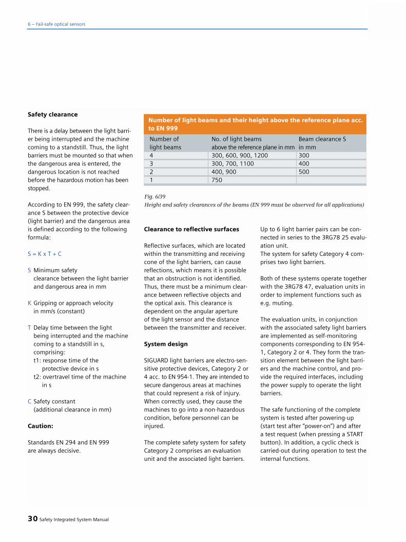
Safety clearance
There is a delay between the light barri-er being interrupted and the machinecoming to a standstill. Thus, the lightbarriers must be mounted so that whenthe dangerous area is entered, thedangerous location is not reachedbefore the hazardous motion has beenstopped.
According to EN 999, the safety clear-ance S between the protective device(light barrier) and the dangerous areais defined according to the followingformula:
S = K x T + C
S Minimum safety clearance between the light barrier and dangerous area in mm
K Gripping or approach velocityin mm/s (constant)
T Delay time between the lightbeing interrupted and the machinecoming to a standstill in s, comprising:t1: response time of the
protective device in st2: overtravel time of the machine
in s
C Safety constant(additional clearance in mm)
Caution:
Standards EN 294 and EN 999are always decisive.
Clearance to reflective surfaces
Reflective surfaces, which are locatedwithin the transmitting and receivingcone of the light barriers, can causereflections, which means it is possiblethat an obstruction is not identified.Thus, there must be a minimum clear-ance between reflective objects andthe optical axis. This clearance isdependent on the angular aperture of the light sensor and the distancebetween the transmitter and receiver.
System design
SIGUARD light barriers are electro-sen-sitive protective devices, Category 2 or4 acc. to EN 954-1. They are intended tosecure dangerous areas at machinesthat could represent a risk of injury.When correctly used, they cause themachines to go into a non-hazardouscondition, before personnel can beinjured.
The complete safety system for safetyCategory 2 comprises an evaluationunit and the associated light barriers.
Up to 6 light barrier pairs can be con-nected in series to the 3RG78 25 evalu-ation unit.The system for safety Category 4 com-prises two light barriers.
Both of these systems operate togetherwith the 3RG78 47, evaluation units inorder to implement functions such ase.g. muting.
The evaluation units, in conjunctionwith the associated safety light barriersare implemented as self-monitoringcomponents corresponding to EN 954-1, Category 2 or 4. They form the tran-sition element between the light barri-ers and the machine control, and pro-vide the required interfaces, includingthe power supply to operate the lightbarriers.
The safe functioning of the completesystem is tested after powering-up(start test after “power-on”) and after a test request (when pressing a STARTbutton). In addition, a cyclic check iscarried-out during operation to test theinternal functions.
30 Safety Integrated System Manual
6 – Fail-safe optical sensors
Number of No. of light beams Beam clearance Slight beams above the reference plane in mm in mm4 300, 600, 900, 1200 3003 300, 700, 1100 4002 400, 900 5001 750
Number of light beams and their height above the reference plane acc.to EN 999
Fig. 6/39
Height and safety clearances of the beams (EN 999 must be observed for all applications)
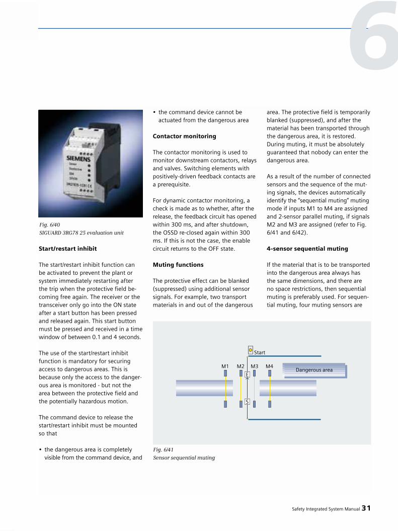
Start/restart inhibit
The start/restart inhibit function can be activated to prevent the plant orsystem immediately restarting afterthe trip when the protective field be-coming free again. The receiver or thetransceiver only go into the ON stateafter a start button has been pressedand released again. This start buttonmust be pressed and received in a timewindow of between 0.1 and 4 seconds.
The use of the start/restart inhibitfunction is mandatory for securingaccess to dangerous areas. This isbecause only the access to the danger-ous area is monitored - but not thearea between the protective field andthe potentially hazardous motion.
The command device to release thestart/restart inhibit must be mountedso that
• the dangerous area is completely visible from the command device, and
• the command device cannot be actuated from the dangerous area
Contactor monitoring
The contactor monitoring is used tomonitor downstream contactors, relaysand valves. Switching elements withpositively-driven feedback contacts area prerequisite.
For dynamic contactor monitoring, acheck is made as to whether, after therelease, the feedback circuit has openedwithin 300 ms, and after shutdown,the OSSD re-closed again within 300ms. If this is not the case, the enablecircuit returns to the OFF state.
Muting functions
The protective effect can be blanked(suppressed) using additional sensorsignals. For example, two transportmaterials in and out of the dangerous
area. The protective field is temporarilyblanked (suppressed), and after thematerial has been transported throughthe dangerous area, it is restored. During muting, it must be absolutelyguaranteed that nobody can enter thedangerous area.
As a result of the number of connectedsensors and the sequence of the mut-ing signals, the devices automaticallyidentify the “sequential muting” mutingmode if inputs M1 to M4 are assignedand 2-sensor parallel muting, if signalsM2 and M3 are assigned (refer to Fig.6/41 and 6/42).
4-sensor sequential muting
If the material that is to be transportedinto the dangerous area always has the same dimensions, and there are no space restrictions, then sequentialmuting is preferably used. For sequen-tial muting, four muting sensors are
Safety Integrated System Manual 31
6
Fig. 6/40
SIGUARD 3RG78 25 evaluation unit
Fig. 6/41
Sensor sequential muting

connected that must be activated in aspecified sequence in order to initiatethe muting operation. They can beactivated in the sequence M1, M2, M3,M4 as well as in the sequence M4, M3,M2, M1. The material being transport-ed must be long enough, as all foursensors must be briefly and simultane-ously activated. The sequential mutingis correctly terminated if the third acti-vated muting sensor is no longer acti-vated.
2-sensor parallel muting
Parallel muting is preferably used inthose plants and systems where the
dimensions of the material being trans-ported are not constant, or where spaceis restricted. Two muting sensors can be used, whosebeams cross behind the protective fieldin the hazardous zone.
Parallel muting is initiated if the twoM2 and M3 signals simultaneouslyswitch without M1 and M4 havingbeen activated or connected - eitherbeforehand or simultaneously. 2-sensor parallel muting can beimplemented at a low cost as only two muting sensors are required - andit is possible to move backwards andforwards within the muting distance.
Overview
A switching strip is a mechanicallyactuated protective device that safelydetects when contact is made to aperson or a part of the body
Sender and receiver are optically andelectrically coupled
An interruption of the light beam,influence of external light sources orfailure of electronic components aresafely detected
The sender power is automaticallyadapted to the length of the switchingstrip
Increased availability by compensatingfor the effects of aging, humidity andaccumulated dirt
Shutdown and run-on travel are inde-pendent of the length of the profile
Features
• Neither gluing nor pre-assembling -required
• Neither technical know-how norspecial tools required
• The system can be easily installedand mounted on-site
• Flexible planning up to shortlybefore actual installation and moun-ting
• Favorably-priced inventory• Downtimes are minimized
32 Safety Integrated System Manual
6 – Fail-safe optical sensors
Fig. 6/42
Sensor parallel muting
6.4 SIGUARD switchingstrips

Applications
Machines and plant construction• Protective covers of machines• Driverless transport systems• Elevating tables• Washing gantries• Elevating platforms • Automatic handling equipment
Doors and gates• The forces occurring are limited
when hitting an obstruction• A suitable profile is selected• The actuation angle for folding
doors/gates is taken into account
Vehicle construction• The forces occurring are limited
when hitting an obstruction• A suitable profile is selected• Reliable, even at high speeds/
velocities• Automatically closing doors• Automatically closing windows
Product family/product groups
The German Trade Association [BG] has certified 3RG78 5 SIGUARD safetyswitch strips for Category 4 acc. to EN 954-1. The fail-safe functionality is achieved using the associated evalu-ation unit.
The system comprises• An evaluation unit,• A mounting strip,• A sensor strip that is used to
implement the shutdown function, • An optical sender and receiver that
monitors the switching strip
Design
Transmitter and receiver units are inser-ted into the hollow space in the rubberprofile at each end. The rubber profilecan be cut to the required length on-site and is resistant to, for example,ozone, oils, solvents, acids and fuels.
Safety Integrated System Manual 33
6
Fig. 6/43
Principle of operation of SIGUARD switching strips


Increasing significance of safetysystems in controllers
Accidents and damage resulting fromfaults and mistakes in plants or machi-nes must, as far as possible, be avoid-ed. This is the reason that legislationassociated with safety at work and toprotecting the environment is becomingincreasingly more stringent. Today, dif-ferent products and systems are oftenbeing used for safety-related functions(electro-mechanical) and standard tasks(classic PLC). When using conventionalwiring and special safety-related buses,as the complexity of the automationtask increases then the following alsoincrease• on one hand the wiring costs and • on the other hand, the engineering
costs.Troubleshooting can take longer andthe availability of the complete plant or system decreases.
This is the reason that machinery con-struction companies and plant operat-ing companies are increasingly decid-ing to have the safety-related taskshandled by the automation compo-nents. This means that the protectionof man, machines and the environ-ment depends on automation systemsfunctioning fault and error-free. This isthe reason that the same high require-ments are placed on safety-relatedelectronic systems as safety-relatedelectro-mechanical components. Bothsystematic as well as randomly occur-ring faults and errors must be con-trolled.
Standard automation and safety-related systems in a completesystem
Up until now, generally, safety-relatedand standard tasks were implementedusing different systems. The result -transitions between systems and twicethe costs. With SIMATIC Safety Integra-ted, the standard automation and safe-ty system are integrated to becomeone innovative total system. ExistingSIMATIC know-how and knowledgeabout safety systems are sufficient toimplement safety-related tasks withSIMATIC.
Well-proven safety technologyusing SIMATIC
Siemens has been established in thearea of safety systems for more than20 years now and since this time hascreated many innovative products andsystems for fail-safe controllers. Withits SIMATIC Safety Integrated, Siemenshas done some pioneering work inmany areas, e.g.
• The first fail-safe programmable logic controller – 1980
• The first fail-safe PROFIBUS-Master with PROFIsafe – 1999
Siemens is still actively working indomestic and international Associationsin drawing-up Standards and Directives,such as e.g. ISO, NAM, DKE, IEC etc.
What does SIMATIC SafetyIntegrated mean for users?
By changing to intelligent controllersand distributed architectures, standardautomation has become significantlymore flexible and open. This thereforesignificantly increases the productivityof your machines and plants. Yourautomation will become even moreefficient if safety technology conse-quentially follows this trend and allowsitself to be seamlessly integrated intothe standard automation environment.This means the following:
• Existing STEP7 know-how can be used - from engineering up to service & maintenance.
• PROFIBUS network structures can be used, also for safety-relevant communications.
• Existing components and infra-structure are used, as far as possible,also for safety systems.
2 Safety Integrated System Manual
7 Fail-safe controllersSIMATIC Safety Integrated
7.1 Overview

Complete integrated system
By integrating safety-related functionsin the automation environment ofTotally Integrated Automation, stan-dard and safety automation growtogether to form a complete seamlesssystem.
SIMATIC Safety Integrated encompass-es the fail-safe SIMATIC controllers aswell as the I/O and engineering withinthe product range of Safety Integrated.When a fault or error occurs, the con-trol or a sub-process can be broughtinto a safety-related state where it isalso kept. These fail-safe controllers arebased on well-proven standard SIMAT-IC PLCs.
PROFIBUS was extended for safety-re-lated communications by the non-pro-prietary PROFIsafe profile. This meansthat safety-related and standard com-munications only require just one stan-dard PROFIBUS cable.
The same engineering and program-ming tools (STEP® 7) are used to engi-neer the standard and safety functionsof fail-safe SIMATIC controllers.
This means that in a SIMATIC controllersthe safety system is seamlessly inte-grated in the standard automation.Thisalso makes it easier for operating per-sonnel to handle the complete plant orsystem. Not only this - engineering
and training costs are also reduced.Another advantage is that extensivediagnostics of safety-related signalscan be directly read-out using standardpanels and HMI devices.
Thanks to the fine resolution of thefail-safe I/O design, safety technologyonly has to be used where it is actuallyrequired. Safety components can be
simply combined with standard com-ponents; Safety-related and non-safe-ty-related programs coexist in morethan one controller as well on a com-mon bus system.
Fail-safe fieldbus devices from othermanufacturers can be simply connect-ed-up using PROFIBUS and the non-proprietary PROFIsafe profile.
Safety Integrated System Manual 3
7.2 Features
Fig. 7/1
Innovation with PLC-based safety solutions
7
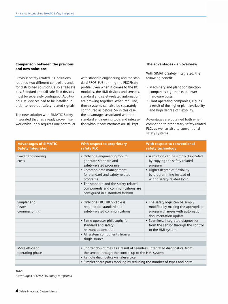
Comparison between the previousand new solutions
Previous safety-related PLC solutionsrequired two different controllers and,for distributed solutions, also a fail-safebus. Standard and fail-safe field devicesmust be separately configured. Additio-nal HMI devices had to be installed inorder to read-out safety-related signals.
The new solution with SIMATIC SafetyIntegrated that has already proven itselfworldwide, only requires one controller
with standard engineering and the stan-dard PROFIBUS running the PROFIsafeprofile. Even when it comes to the I/Omodules, the HMI devices and sensors,standard and safety-related automationare growing together. When required,these systems can also be separatelyconfigured as before. So in this case,the advantages associated with thestandard engineering tools and integra-tion without new interfaces are still kept.
The advantages - an overview
With SIMATIC Safety Integrated, thefollowing benefit:
• Machinery and plant construction companies e.g. thanks to lower hardware costs.
• Plant operating companies, e.g. asa result of the higher plant availabilityand high degree of flexibility.
Advantages are obtained both whencomparing to proprietary safety-relatedPLCs as well as also to conventionalsafety systems.
4 Safety Integrated System Manual
Lower engineering • Only one engineering tool to • A solution can be simply duplicatedcosts generate standard and by copying the safety-related
safety-related programs program• Common data management • Higher degree of flexibility
for standard and safety-related by programming instead ofprograms wiring safety-related logic
• The standard and the safety-related components and communications are configured in a standard fashion
Simpler and • Only one PROFIBUS cable is • The safety logic can be simplyfaster required for standard and- modified by making the appropriatecommissioning safety-related communications program changes with automatic
documentation update• Same operator philosophy for • Seamless, integrated diagnostics
standard and safety- from the sensor through the controlrelevant automation to the HMI system
• All system components from a single source
More efficient • Shorter downtimes as a result of seamless, integrated diagnostics fromoperating phase the sensor through the control up to the HMI system
• Remote diagnostics via teleservice• Simpler spare parts stocking by reducing the number of types and parts
Advantages of SIMATIC With respect to proprietary With respect to conventionalSafety Integrated safety PLC safety technology
7 – Fail-safe controllers SIMATIC Safety Integrated
Table:
Advantages of SIMATIC Safety Integrated

Using SIMATIC Safety Integrated
The range of fail-safe SIMATIC con-trollers encompasses safety solutionsthat are widely scalable - both for pro-duction as well as process automation.
• Safety and the protection of people and machines have topmost priority in production automation.
• In process automation, it is especiallyimportant that the system availabilityis maintained. At the same time, protection must be provided against unexpected process hazards and the risk of an accident or incident mustbe appropriately reduced.
The use of SIMATIC Safety Integratedallows all of the important Standardsto be fulfilled to protect man, machinesand the environment.
At home in all industry sectors
The main applications of SIMATICSafety Integrated are, for example, as follows:
• Factory automationAutomobile industry, conveyor sys-tems, presses, all types of processingmachinery, machine tools, etc. pas-senger transport, e.g. cable railways,elevating platforms, amusement rides, etc.
• Process automationOil & gas, chemical, pharmaceutical, petrochemical, refineries,
Typical applications include: Furnace controls, emergency shut-down (ESD), process shutdown (PSD)and fire & gas (F&G)
The seamless, integrated characteris-tics of SIMATIC Safety Integrated areespecially important for compositeapplications from the main sectors inthe hybrid industry - among others, for communications and shared I/O.
Safety Integrated System Manual 5
7.3 Applications
7
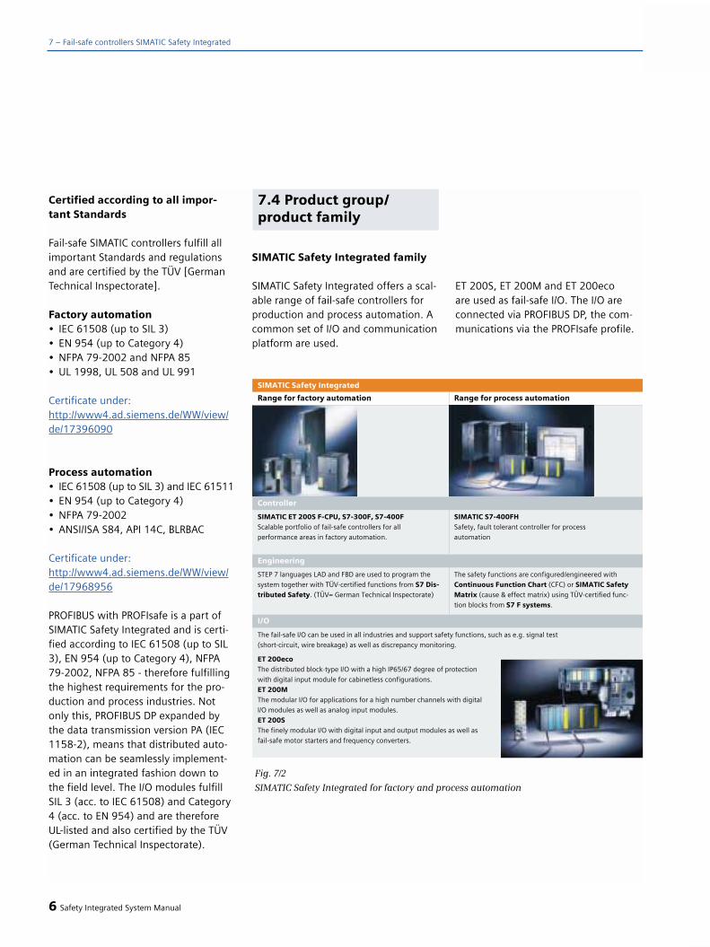
Certified according to all impor-tant Standards
Fail-safe SIMATIC controllers fulfill allimportant Standards and regulationsand are certified by the TÜV [GermanTechnical Inspectorate].
Factory automation• IEC 61508 (up to SIL 3)• EN 954 (up to Category 4)• NFPA 79-2002 and NFPA 85• UL 1998, UL 508 and UL 991
Certificate under:http://www4.ad.siemens.de/WW/view/de/17396090
Process automation• IEC 61508 (up to SIL 3) and IEC 61511• EN 954 (up to Category 4)• NFPA 79-2002• ANSI/ISA S84, API 14C, BLRBAC
Certificate under:http://www4.ad.siemens.de/WW/view/de/17968956
PROFIBUS with PROFIsafe is a part ofSIMATIC Safety Integrated and is certi-fied according to IEC 61508 (up to SIL3), EN 954 (up to Category 4), NFPA79-2002, NFPA 85 - therefore fulfillingthe highest requirements for the pro-duction and process industries. Notonly this, PROFIBUS DP expanded bythe data transmission version PA (IEC1158-2), means that distributed auto-mation can be seamlessly implement-ed in an integrated fashion down tothe field level. The I/O modules fulfillSIL 3 (acc. to IEC 61508) and Category4 (acc. to EN 954) and are thereforeUL-listed and also certified by the TÜV(German Technical Inspectorate).
SIMATIC Safety Integrated family
SIMATIC Safety Integrated offers a scal-able range of fail-safe controllers forproduction and process automation. Acommon set of I/O and communicationplatform are used.
ET 200S, ET 200M and ET 200eco are used as fail-safe I/O. The I/O areconnected via PROFIBUS DP, the com-munications via the PROFIsafe profile.
6 Safety Integrated System Manual
7.4 Product group/product family
7 – Fail-safe controllers SIMATIC Safety Integrated
Fig. 7/2
SIMATIC Safety Integrated for factory and process automation

Controllers for factory automation
The following F-CPUs are available forfactory automation:
• IM 151-7 F-CPU of the ET 200S• CPU 315F and CPU 317F of the
S7-300• CPU 416F of the S7-400
These CPUs are based on standardCPUs - their hardware and operatingsystems have been expanded by vari-ous protective mechanisms to be ableto execute safety-related programs.
The safety-related program is complete-ly programmed using STEP 7 in thestandard languages LAD and FBD. In addition to STEP 7, the “S7 DistributedSafety” option package is required. Using pre-configured, certified blocks,“S7 Distributed Safety” provides sup-port when parameterizing the fail-safeI/O and when programming.
When executing non-safety-relatedprograms there are absolutely norestrictions regarding the program-ming language.
Controllers for process automation
The CPUs 414H and CPU 417H withsafety-related functions from the S7-400 are available for applications in the process industry. Safety-relatedapplications in the process industryrequire a special software package “S7 F system”. Fail-safe applications up to SIL 3 can be handled using justone CPU. “S7 F systems” support theconfiguration of safety-related I/O andlogic programming.
Two CPUs can be used to increase thelevel of system availability to fulfillrequirements relating to fail-safety andfault tolerance. It is also extremely sim-ple to integrate into the SIMATIC PCS 7process control system. This results inthe following advantages:
• One engineering system for standardand fail-safe applications.
• The safety-related system is homo-geneously integrated into the auto-mation system (AS) of SIMATIC PCS 7.
• User-friendly visualization of the process values integrated in the operator station (OS) of SIMATIC PCS 7.
• Safety-related fault messages areautomatically incorporated in theprocess visualization, with the same time stamp.
• No complex coupling between theDistributed Control System (DCS) and SIMATIC Safety Integrated, e.g. via Modbus.
Safety-related functions are configuredin the Continuous Function Chart(CFC). Certified function blocks providesupport when engineering/configuringtherefore saving both time and money.
Safety Integrated System Manual 7
7
Fig. 7/3
CPUs for factory automation
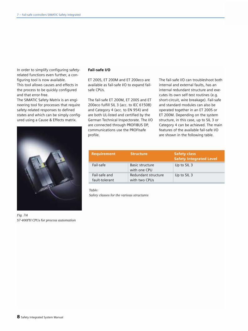
7 – Fail-safe controllers SIMATIC Safety Integrated
In order to simplify configuring safety-related functions even further, a con-figuring tool is now available. This tool allows causes and effects inthe process to be quickly configuredand that error-free. The SIMATIC Safety Matrix is an engi-neering tool for processes that requiresafety-related responses to definedstates and which can be simply config-ured using a Cause & Effects matrix.
Fail-safe I/O
ET 200S, ET 200M and ET 200eco areavailable as fail-safe I/O to expand fail-safe CPUs.
The fail-safe ET 200M, ET 200S and ET200eco fulfill SIL 3 (acc. to IEC 61508)and Category 4 (acc. to EN 954) andare both UL-listed and certified by theGerman Technical Inspectorate. The I/Oare connected through PROFIBUS DP, communications use the PROFIsafeprofile.
The fail-safe I/O can troubleshoot bothinternal and external faults, has aninternal redundant structure and exe-cutes its own self-test routines (e.g.short-circuit, wire breakage). Fail-safeand standard modules can also beoperated together in an ET 200S or ET 200M. Depending on the systemstructure, in this case, up to SIL 3 orCategory 4 can be achieved. The mainfeatures of the available fail-safe I/Oare shown in the following table.
8 Safety Integrated System Manual
Fig. 7/4
S7-400FH CPUs for process automation
Fail-safe Basic structure Up to SIL 3with one CPU
Fail-safe and Redundant structure Up to SIL 3fault-tolerant with two CPUs
Requirement Structure Safety classSafety Integrated Level
Table:
Safety classes for the various structures

((Fig._7_4_1.eps))
ET 200MImplementing the safety functions
The safety-related functions are exe-cuted by the safety-related program inthe CPU in conjunction with fail-safeI/O modules. In so doing, standard I/Oand fail-safe I/O can be combined. Forthe ET 200M, electrical isolation for SIL3 and Category 4 applications is real-ized using an isolating module and forthe ET 200S, by configuring load cir-cuits with power modules (PMs).
Both safety-related as well as standardcommunications between the centralmodule and I/O (safety-related or stan-dard) are realized along PROFIBUS DPwith the PROFIsafe profile.
Principle of the safety-relatedfunction for SIMATIC SafetyIntegrated
The principle of operation is timeredundancy and diversity instead ofstructural redundancy. The safety-relat-ed input signals are processed diverse-ly and redundantly in time.
Safety Integrated System Manual 9
7Features Finely modular I/O with Modular S7-300 I/O for Digital block I/O in a high
up to 8 channels per module applications with a high Number IP65/67 degree of protectionin degree of protection IP20 of channels with up to 24
channels per module in degree of protection IP20
Digital inputs To connect digital To connect digital To connect digitalsensors/encoders sensors/encoders sensors/encoders• 4/8 F-DI 24V DC • 24 F-DI 24V DC • 4/8 F-DI 24V DC
• 8 F-DI NAMURDigital outputs To connect digital To connect digital
actuators/loads actuators/loads• 4 F-DO 24V DC/2A • 10 F-DO 24V DC/2A
• 8 F-DO 24V DC/2A (PM switch.)Analog inputs To connect analog
sensors/encoders• 6 F-AI 4-20 mA / 13 bit
Power modules To monitor and protect the load and encoder powersupply voltages• PM-D F 24 V DC• PM-E F PM• PM-E F PP
Motor starters The fail-safe motor starters have,in addition to a circuit-breaker/contactor combination, also a safety-related electronic evaluationcircuit for fault detection. If, whenan Emergency Stop situationoccurs, the switching contactor fails, the evaluation electronics detects a fault and opens thecircuit-breaker in the motor starterin a safety-related fashion.
Frequency converters The fail-safe frequency converterspermit the following safetyfunctions to be implemented for variable-speed induction motors: • Safe standstill, • Safe braking ramp, • Safely reduced speed.
I/O ET 200S ET 200M ET 200eco*)

Programming in factory automa-tion
No additional programming know-howis required when using the “S7 Distri-buted Safety” software package. This is because the safety-related programsfor the fail-safe CPUs are programmedusing the usual STEP7 standard lan-guages, ladder diagram (LAD) andfunction diagram (FBD). Using a specialinput when compiling, it is ensuredthat the program, generated by theuser, is executed in a safety-relatedfashion.
The F library with pre-configured blocksfor safety-related functions that havebeen certified by the Germany TechnicalInspectorate is an additional compo-nent of this software package. Thislibrary includes function blocks such as Emergency Stop, protective door, 2-hand operator control, muting forlight curtains etc.
Further, “S7 Distributed Safety” supportsthe comparison of safety-related pro-grams. Finally, the acceptance of theplant or system is simplified as a resultof the generated program printout.
An option package with certified fur-nace blocks is available for furnaceapplications.
Configuring and engineering inthe process automation
“S7 F systems” is used to engineer thehardware and configure the safety-related process application accordingto IEC 61511 and expands the S7-400FHcontroller by safety-related functions. It makes it easier to generate the safe-ty-related program by providing an F library with pre-configured blocks,certified by the German TechnicalInspectorate according to SIL 3 IEC61508. Further, it simplifies the docu-mentation of the safety-related pro-gram, e.g. by managing and adminis-trating the appropriate signatures.
The fail-safe safety-related programcan either be configured using CFC or the Safety Matrix.
CFC is especially suitable for dynamicprocesses - e.g. in the chemical andpetrochemical industries (hydrocrack-ers). Using CFC, certified blocks fromthe F library of S7 F systems or theoptional furnace package can becalled-up and interconnected. Theoptional furnace package includes an F library with blocks for industrialgas-fired and oil-fired furnaces. Theblocks have been certified by theGerman Technical Inspectorate acc. toEN 61508 SIL 3 and TRD Standard 411and 412 for thermo and steam boilers.
The Safety Matrix is an innovative engi-neering tool for processes that requiresafety-related responses to definedstates and events and can be simplyengineered using the Cause & Effectsmatrix. The Cause & Effects analysis is
10 Safety Integrated System Manual
7 – Fail-safe controllers SIMATIC Safety Integrated
Fig. 7/5Example of the SIMATIC Safety Matrix for S7-400FH
7.5 Engineering
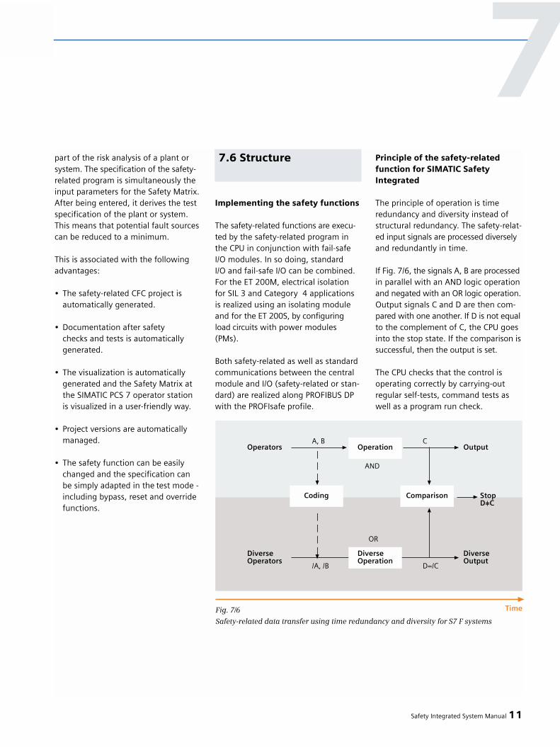
part of the risk analysis of a plant orsystem. The specification of the safety-related program is simultaneously theinput parameters for the Safety Matrix.After being entered, it derives the testspecification of the plant or system.This means that potential fault sourcescan be reduced to a minimum.
This is associated with the followingadvantages:
• The safety-related CFC project isautomatically generated.
• Documentation after safetychecks and tests is automaticallygenerated.
• The visualization is automatically generated and the Safety Matrix at the SIMATIC PCS 7 operator station is visualized in a user-friendly way.
• Project versions are automaticallymanaged.
• The safety function can be easily changed and the specification canbe simply adapted in the test mode - including bypass, reset and override functions.
Implementing the safety functions
The safety-related functions are execu-ted by the safety-related program inthe CPU in conjunction with fail-safeI/O modules. In so doing, standard I/O and fail-safe I/O can be combined. For the ET 200M, electrical isolation for SIL 3 and Category 4 applicationsis realized using an isolating moduleand for the ET 200S, by configuring load circuits with power modules(PMs).
Both safety-related as well as standardcommunications between the centralmodule and I/O (safety-related or stan-dard) are realized along PROFIBUS DPwith the PROFIsafe profile.
Principle of the safety-relatedfunction for SIMATIC SafetyIntegrated
The principle of operation is timeredundancy and diversity instead ofstructural redundancy. The safety-relat-ed input signals are processed diverselyand redundantly in time.
If Fig. 7/6, the signals A, B are processedin parallel with an AND logic operationand negated with an OR logic operation.Output signals C and D are then com-pared with one another. If D is not equalto the complement of C, the CPU goesinto the stop state. If the comparison issuccessful, then the output is set.
The CPU checks that the control isoperating correctly by carrying-outregular self-tests, command tests aswell as a program run check.
Safety Integrated System Manual 11
77.6 Structure
Fig. 7/6
Safety-related data transfer using time redundancy and diversity for S7 F systems

Functions of the fail-safe controller
The fail-safe CPUs have the followingproperties:
• Comprehensive self-tests and self-diagnostics in order to check the fail-safe CPU state.
• In addition to the fail-safe program,a standard program can also run on a CPU (coexistence) that is not subject to any restrictions.
• Fail-safe communications between CPUs.
• The same diagnostics and signaling functions as a standard SIMATIC S7-CPU.
Functions of the fail-safe I/O
The Fail-safe I/O can diagnose internaland external faults, have an internalredundant structure and execute theirown self-test routines (e.g. short-circuit,wire breakage). Fail-safe shutdown isrealized without any additional safetyrelay. Further, the discrepancy time,specified in the form of the parameter-ization, is autonomously monitored bythe I/O module.
12 Safety Integrated System Manual
7 – Fail-safe controllers SIMATIC Safety Integrated
7.7 Functions
Fig. 7/7Structure of the ET 200S configurator
IM = Interface module,
PM = Power module,
PM E = Power module for the electronics module,
PM EF = Power module for the fail-safe electronics module,
EM = Electronics module

Fail-safe and standard modules can also be combined in an ET 200S or ET 200M. Depending on the systemstructure, up to SIL 3 or Category 4 can be achieved.
Configurator for ET 200S
In order to correctly configure an ET 200SStation, an ET 200S configurator hasbeen available from the electronic CA01Catalog since April 2003. This providessupport when combining modulesaccording to the following specifica-tion. The configuration of I/O modulesand motor starters with and withoutsafety-related technology is analyzed.
Starting from the IM fail-safe headermodule, a decision must be made as towhich safety Category the load circuitswith the modules should fulfill. Themodules can then be configured. Thefunction of the configurator is explainedin the following using 2 examples.
1. Standard configuration with PM-E,F-DI and F-DO modules to achieveCategory 4 and SIL 3.
A load circuit with fail-safe F-DI and F-DO modules fulfills the highest safetycategory, Category 4 and SIL 3. Poweris fed-in using a standard PM-E powermodule. If additional standard modulesare configured in a load circuit with Fmodules, then as a maximum, safetyCategory 3 or SIL 2 can be achieved.
2. Favorably-priced configuration withPM-E F and downstream standard 4-DOmodules to achieve Category 3 or SIL 2.
A load circuit with PM-E F modules anddownstream standard 2-DO modulesfulfills, as a maximum, safety Category3 or SIL 2. It is even possible to shutdown according to SIL 3 using a relayoutput integrated in the PM-E F.
Safety Integrated System Manual 13
7

Typical configuration examples
Two configuration examples for SIMATICSafety Integrated are listed below –one with the focus on factory auto-mation and one from the process automation environment
Both the standard communications aswell as also the safety-related commu-nications are realized along the samestandard PROFIBUS cable using thenon-proprietary PROFIsafe bus profilespecifically developed for safety systems.
Factory automation
Controllers
• Fail-safe CPUs for ET 200S, S7-300, S7-400
I/O
• SIMATIC ET 200M with a largernumber of I/O modules, finely modular SIMATIC ET 200S (IP20) and SIMATIC ET 200eco (IP65/67)
• NAMUR modules of SIMATIC ET 200S for hazardous zones
• Depending on the requirement, can be expanded by standardand fail-safe modules
• Fail-safe modules: The internalstructure is completely redundantand diverse
• Extensive diagnostic functionsto detect internal and external faults
• Safety functions are included in the fail-safe signal modules
• LS4 laser scanner with direct connection to PROFIsafe
• Motor starters for ET 200S• Frequency converters for ET 200S
Communications
• Standard PROFIBUS DP withPROFIsafe profile
14 Safety Integrated System Manual
7 – Fail-safe controllers SIMATIC Safety Integrated
7.8 Examples
Fig. 7/8Configuration example, factory automation with a simple structure
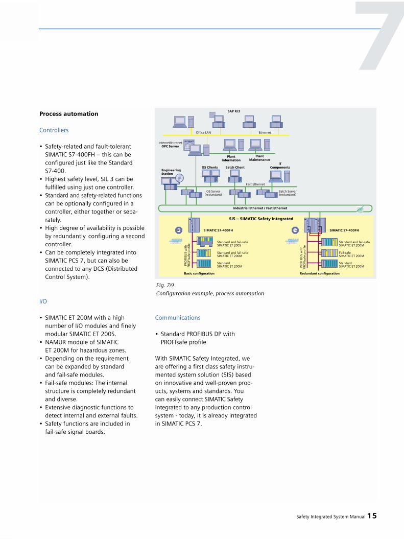
Process automation
Controllers
• Safety-related and fault-tolerantSIMATIC S7-400FH – this can be configured just like the Standard S7-400.
• Highest safety level, SIL 3 can be fulfilled using just one controller.
• Standard and safety-related functionscan be optionally configured in a controller, either together or sepa-rately.
• High degree of availability is possibleby redundantly configuring a secondcontroller.
• Can be completely integrated into SIMATIC PCS 7, but can also beconnected to any DCS (Distributed Control System).
I/O
• SIMATIC ET 200M with a high number of I/O modules and finely modular SIMATIC ET 200S.
• NAMUR module of SIMATIC ET 200M for hazardous zones.
• Depending on the requirement can be expanded by standardand fail-safe modules.
• Fail-safe modules: The internalstructure is completely redundantand diverse.
• Extensive diagnostic functions to detect internal and external faults.
• Safety functions are included in fail-safe signal boards.
Communications
• Standard PROFIBUS DP withPROFIsafe profile
With SIMATIC Safety Integrated, we are offering a first class safety instru-mented system solution (SIS) based on innovative and well-proven prod-ucts, systems and standards. You can easily connect SIMATIC SafetyIntegrated to any production controlsystem - today, it is already integratedin SIMATIC PCS 7.
Safety Integrated System Manual 15
7
Fig. 7/9
Configuration example, process automation

Programming example - factory automation
The Emergency Stop example in Fig.7/11 shows how stop functions can beimmediately (Category 0) implement-ed or with a delay (Category 1). Theacknowledge button is used as startinput.
Programming time and costs are mini-mized thanks to the distributed faultevaluation for ET 200 modules. Forinstance, the discrepancy time is con-figured when configuring the hard-ware. This is evaluated in the moduleand only a signal appears in the PLCprogram. The signal determined fromthe system can therefore be extremelyeasily processed in the program andcomplex calculations are eliminated.
16 Safety Integrated System Manual
7 – Fail-safe controllers SIMATIC Safety Integrated
Fig. 7/11
Programming example for “Emergency Stop”
Fig. 7/10
Programming with a function chart
Programming screen, factory automation

Configuring screenprocess automation
CFC allows safety-related functions tobe graphically configured. Certifiedfunctions blocks can be directly usedfrom the library.
As an alternative, the SIMATIC SafetyMatrix engineering tool can be usedthat automatically compiles cause &effect links in the CFC and can be easi-ly integrated and visualized in PCS 7.
Safety Integrated System Manual 17
Fig. 7/13
From a Cause & Effect table, the Safety Matrix generates a program that can be run
7
Fig. 7/12
Graphically configuring the S7-400 FH using the continuous function chart (CFC)
engineering tool

18 Safety Integrated System Manual
7 – Fail-safe controllers SIMATIC Safety Integrated
7.9 Technical data
*) PFD = Average probability of failure on demand*) PFH = Probability of a dangerous failure per hour
Packaging design ET 200S S7-300 with central and/or S7-400 with distributeddistributed fail-safe I/O fail-safe I/O
Applications • Distributed applica- • Medium • Medium up to upper • Uppertions in the lower performance range performance range performance rangeperformance range
• Stand alone systemsRAM 96 kB 192 kB 512 kB 1.4 MB data
1.4 MB codeLoad memory 64 kB - 8 MB 64 kB - 8 MB 64 kB - 8 MB 256 kb integrated(can be inserted) 64 kB - 64 MBFlags 2 kbit 16 kbit 64 kbit 128 kbitFB/FC/DB 512/512/511 2048/2048/1023 2048/2048/2047 2048/2048/4095Fail-safe I/O Up to 28 Up to 320 > 500 > 1000Peripheral address 244 B/244 B 2 kB/2 kB 8 kB/8 kB 16 kB/16 kBarea I/OProcess image I/O 128 B/128 B 384 B/384 B 1 kB/1 kB 16 kB/16 kBInterfaces MPI/DP MPI and DP MPI/DP and DP MPI/DP and DPPFD*) 1.59E-05 2.38E-05 4.76E-05 4.76E-05PFH*) 3.62E-10 5.42E-10 1.09E-09 1.09E-09Dimensions 60 x 120 x 75 40 x 125 x 130 80 x 125 x 130 25 x 290 x 219Main Order No. 6ES7 151-7FA.. 6ES7 315-6FF.. 6ES7 317-6FF.. 6ES7 416-2FK..
CPU IM 151-7 F-CPU CPU 315F-2 DP CPU 317F-2 DP CPU 416F-2

Safety Integrated System Manual 19
Library Certified blocks, Certified furnacee,g, Emergency Stop, blocks2-hand-control, muting, door monitoring
Prerequisite STEP 7 S7 Distributed SafetyEngineering- 1 license is required per engineering stationPackageRuntime package 1 license is required per CPUMain Order No. 6ES7 833-1FC.. 9AL3 100-1AD..
RAM 768 kB data 10 MB data(integrated) 768 kB code 10 MB code Load memory 256 kB(integrated, RAM)Load memory up to 64 MB(can be expanded, RAM/FEPROM)Flags 64 kbitFB/FC/DB 2048/2048/4095 6144/6144/8192I/O address 8 kB/8 kB 16 kB/16 kBarea I/OProcess image I/O 8 kB/8 kB 16 kB/16 kBInterfaces MPI/DP and DPPFD*) 1.24 E-04 still not available
PFH*) 1.42 E-09 still not available
Dimensions 25 x 290 x 219Main Order No. 6ES7414-4H... 6ES7417-4H...
CPUs process automation
Option package S7 Distributed Safety Furnace
CPU CPU 414-4H CPU 417-4H
7

20 Safety Integrated System Manual
7 – Fail-safe controllers SIMATIC Safety Integrated
Library Approx. 50 certified Certified furnacebasic function blocks blocks
Prerequisites • STEP 7 • S7 F systems• CFC• S7-SCL
Engineering package 1 license is required per engineering stationRuntime package 1 license is required for each CPUMain Order No. 6ES7 833-1CC.. 9AL3 100-1AA..
Number of inputs 24 (1-channel for 8 (1-channel) 10 8 6 (2-channel for
and outputs SIL 2 sensors) 4 (2-channel) SIL 3-sensors)
12 (2-channel for 13 bit
SIL 3 sensors)
Input or 24 V DC NAMUR 24 V DC 24 V DC --
output voltage P-M switching
Alarms Diagnostic alarm Diagnostic alarm Diagnostic alarm Diagnostic alarm --
Input current/ -- -- 2 A per channel for 2 A per channel for 4-20 mA
output current signal “1" signal ”1"
PFD*) SIL2: 1.55E-06 SIL2: 2.74E-06 6.97E-06 Still not available 4.96E-08
SIL3: 4.99E-08 SIL3: 4.83E-08
PFH*) SIL2: 1.77E-11 SIL2: 3.13E-11 7.96E-11 Still not available 5.66E-13
SIL3: 5.70E-13 SIL3: 5.51E-13
Main Order No. 6ES7 326-1BK..-.... 6ES7 326-1RF..-.... 6ES7 326-2BF..-.... 6ES7 326-2BF4.-... 6ES7 336-1HE..-....
No. of 4 (2-channel for 4 for 24 V/2 A 6 shutdown groups 2 relays Up to 2 SIL 3 outputs
inputs/outputs SIL 3 sensors) each 3A (total current 10 A) for 24 V/2 A,
8 (1-channel for (total current 5 A) 2 relays (total current 10 A)
SIL 2 sensors)
Input and 24 V DC 24 V DC 24 V DC 24 V DC 24 V DC
output voltage
PFD*) SIL2: << 1.00E-03 << 1.00E-05 Still not available Still not available SIL2: << 1.00E-05
SIL3: << 1.00E-05 SIL3: << 1.00E-05
PFH*) SIL2: << 1.00E-08 << 1.00E-10 Still not available Still not available SIL2: << 1.00E-10
SIL3: << 1.00E-10 SIL3: << 1.00E-10
Main Order No. 6ES7 138-4FA..-.... 6ES7 138-4FB..-.... 3RK1903-3BA..-.... 6ES7 138-4CF4.-.... 6ES7 138-4CF..-....
Common/shared I/O
Option package S7 F systems Furnace
Fail-safe Digital input Digital input Digital output Digital output Analog input-
S7-300 signal- SM 326 F SM 326 F SM 326 F SM 326 F module SM 336 F
modules DI 24 x 24 V DC 8 x (NAMUR) DO 10 x 24 V DC/2A DO 8 x 24 V DC/2A
Fail-safe Digital input Digital output Power module PM Power module PM Power module PM
ET 200S modules 4/8 F-DI 24 V DC 4 F-DO 24 V DC PM-D F 24 V DC PM-E F pp 24 V DC PM-E F pm 24 V DC

Safety Integrated Systemhandbuch 21
Power at 500 V 7.5 kWRated operating current IE 16 AShort-circuit-breaking capacity 50 kA at 400 VCoding Can be assigned to 1 of 6
shutdown groupsMain Order No., motor starters 3RK1301-0.B13-.AA2Main Order No., terminal module 3RK1903-3A...
Failsafe Contact Multiplier F-CMContacts 4 NODiagnostics Power failure, device errorSwitching capacity 1.5 A / 24 VMain Order No. 3RK1 903-3CA..
Failsafe Power Module PM-D F X1 (input terminal module)Operation Standalone with external
safety systemDouble terminals for shutdown groups 6Diagnostics power failureMain Order No. 3RK1 903-3DA..
Failsafe Motor Starter
Power rating Up to 4.0 kWMain Order No. 6SL32 44-05..-....
Fail-safe frequency converter
No. of inputs 4 (2-channel for SIL 3 sensors)8 (1-channel for SIL 3 sensors)
Input voltage 24 V DCPFD*) SIL2: << 1.00E-03
SIL3: << 1.00E-05PFH*) SIL2: << 1.00E-08
SIL3: << 1.00E-10Main Order No. 6ES7 148-3FA..-....
Digital block I/O ET 200eco
7


Drives and CNC control systemswith integrated safety
We have extremely high demands tofulfill when it comes to our MotionControl systems and variable-speeddrives for machine tool and productionmachines: They integrate all of therequirements relating to production,market and industry sector. For ourcustomers, this plays a significant rolein increasing quality and productivity.Certified safety functions represent anintegral component of our standardproducts and in addition to affordinghighly effective protection for man andmachine, they also have a significantpositive impact on increasing the pro-ductivity of our customers.
Safety measures must be provided onmachines to protect personnel againstpotentially hazardous machine motion.These are especially used to preventhazardous machine motion when pro-tective devices and guards are open.These functions include monitoringpositions, e.g. end positions, monito-ring speeds and stopping or shutdownin hazardous situations.
Up until now, external devices weremainly used to implement these safetymeasures. These include contactors,switches, cams and monitoring devices.
When a hazardous situation is detect-ed, generally, these devices initiatecontact-based switching operations in the power circuit that stop thepotentially hazardous motion - refer to Fig. 8/1.
When integrating safety functions, drivesystems and CNC controls handle, inaddition to their actual function, alsosafety functions. Extremely short res-ponse times can be achieved due tothe short data path from sensing thesafety relevant information, e.g. speedor position, up to evaluation.
Generally, systems with integratedsafety technology respond extremelyquickly when limit values are exceededor violated, e.g. position or speed limitvalues. This can be extremely signifi-cant for the required monitoring result.The integrated safety technology candirectly control the power semiconduc-tors in the drive control unit withoutusing electro-mechanical switchingoperations in the power circuit. Thisalso means that the system is lessprone to faults and disturbances. Thewiring and cabling costs are reduced as a result of the integration.
2 Safety Integrated System Manual
8 Fail-safe motion control systems
8.1 SINUMERIK Safety Integrated – the safety package formachine tools
Fig. 8/1
External safety technology, integrated safety technology

Brief description
Functional scope
“SINUMERIK Safety Integrated” offerstype-tested safety functions that canbe used to implement highly effectivepersonnel and machine protection inline with that required in practice. Allsafety functions fulfill the requirementsof Category 3 acc. to EN 954-1 and arepermanent components of the basicsystem. Neither additional sensors norevaluation units are required.
This means the following:
Lower installation costs at the machineand a low-profile electrical cabinet.
The functionality includes:
• Functions to safely monitor the speed, standstill and positioning
• Functions to logically interlocksignals in a safety-related fashion
Sensors and actuators, for example,EMERGENCY STOP pushbuttons, lightcurtains, valves or brakes, can be directlycoupled to a two-channel I/O or to fail-safe modules. The logical combinationand the responses are realized internal-ly using safety-related technology. Allsafety-related system errors always re-sult in the potentially hazardous motionbeing safely brought to a standstill, orthe power feed to the motor is quicklyand contactlessly disconnected. Thedrive can always be stopped optimallyadapted to the operating state of the
machine. This means, for example, inthe setting-up mode, when the protec-tive door is open, the machine can bestopped as quickly as possible (this isoptimum for personnel protection) andin the automatic mode with closed pro-tective door, along the machining path(optimum for machine protection).
In all of the operating modes, the safe-ty functions are available and can com-municate with the process itself viasafety-related input/output signals. Theyfulfill the requirements of Category 3(acc. to EN 954-1). The complete func-tional scope was certified in the formof a prototype test by the BGIA [GermanInstitute for Safety and Health] in St.Augustin.
This means the following:
A high degree of protection for person-nel in the setting-up mode and addi-tional protection for the machine, tooland workpiece in the automatic mode.
These safety functions offer an intelli-gent intervention, previously unknown,directly down to the electric drives andmeasuring systems. Reliable function,fast response and a broad acceptancemean that these certified safety systemsare highly effective.
Basic structure
A two-channel system structure withdiversity is created using the existing-multi-processor structure. The safetyfunctions are redundantly incorporatedin the NC, drive and internal PLC. Theprocess quantities and safety-relatedsystem data are cross-monitored; alsorefer to Fig. 8/3.
Safety Integrated System Manual 3
8
Fig. 8/2
The basic SINUMERIK/SIMODRIVE system
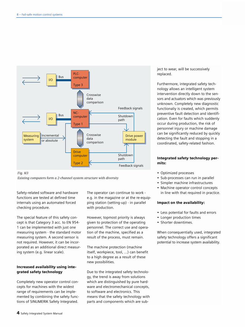
Safety-related software and hardwarefunctions are tested at defined timeinternals using an automated forcedchecking procedure.
The special feature of this safety con-cept is that Category 3 acc. to EN 954-1 can be implemented with just onemeasuring system - the standard motormeasuring system. A second sensor isnot required. However, it can be incor-porated as an additional direct measur-ing system (e.g. linear scale).
Increased availability using inte-grated safety technology
Completely new operator control con-cepts for machines with the widestrange of requirements can be imple-mented by combining the safety func-tions of SINUMERIK Safety Integrated.
The operator can continue to work -e.g. in the magazine or at the re-equip-ping station (setting-up) - in parallelwith production.
However, topmost priority is alwaysgiven to protection of the operatingpersonnel. The correct use and opera-tion of the machine, specified as aresult of the process, must remain.
The machine protection (machineitself, workpiece, tool, ...) can benefitto a high degree as a result of thesenew possibilities.
Due to the integrated safety technolo-gy, the trend is away from solutionswhich are distinguished by pure hard-ware and electromechanical concepts,to software and electronics. Thismeans that the safety technology withparts and components which are sub-
ject to wear, will be successivelyreplaced.
Furthermore, integrated safety tech-nology allows an intelligent systemintervention directly down to the sen-sors and actuators which was previouslyunknown. Completely new diagnosticfunctionaliy is created, which permitspreventive fault detection and identifi-cation. Even for faults which suddenlyoccur during production, the risk ofpersonnel injury or machine damagecan be significantly reduced by quicklydetecting the fault and stopping in acoordinated, safety-related fashion.
Integrated safety technology per-mits:
• Optimized processes• Sub-processes can run in parallel• Simpler machine infrastructures• Machine operator control concepts
in line with that required in practice.
Impact on the availability:
• Less potential for faults and errors• Longer production times• Shorter downtimes.
When consequentially used, integratedsafety technology offers a significantpotential to increase system availability.
4 Safety Integrated System Manual
8 – Fail-safe motion control systems
Fig. 8/3
Existing computers form a 2-channel system structure with diversity
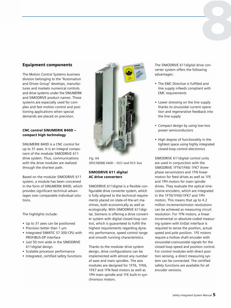
Equipment components
The Motion Control Systems businessdivision belonging to the “Automationand Drives Group” develops, manufac-tures and markets numerical controlsand drive systems under the SINUMERIKand SIMODRIVE product names. Thesesystems are especially used for com-plex and fast motion control and posi-tioning applications when specialdemands are placed on precision.
CNC control SINUMERIK 840D – compact high technology
SINUMERIK 840D is a CNC control forup to 31 axes. It is an integral compo-nent of the modular SIMODRIVE 611drive system. Thus, communicationswith the drive modules are realizedthrough the shortest path.
Based on the modular SIMODRIVE 611system, a module has been conceivedin the form of SINUMERIK 840D, whichprovides significant technical advan-tages over comparable individual solu-tions.
The highlights include:
• Up to 31 axes can be positioned• Precision better than 1 µm• Integrated SIMATIC S7-300-CPU with
PROFIBUS-DP interface• Just 50 mm wide in the SIMODRIVE
611digital design• Scalable processor performance• Integrated, certified safety functions
SIMODRIVE 611 digital AC drive converters
SIMODRIVE 611digital is a flexible con-figurable drive converter system, whichis fully aligned to the technical require-ments placed on state-of-the-art ma-chines, both economically as well asecologically. With SIMODRIVE 611digi-tal, Siemens is offering a drive convert-er system with digital closed-loop con-trol, which is guaranteed to fulfill thehighest requirements regarding dyna-mic performance, speed control rangeand smooth running characteristics.
Thanks to the modular drive systemdesign, drive configurations can beimplemented with almost any numberof axes and main spindles. The axismodules are designed for 1FT6, 1FK6,1FK7 and 1FN feed motors as well as1PH main spindle and 1FE built-in syn-chronous motors.
The SIMODRIVE 611digital drive con-verter system offers the followingadvantages:
• The EMC Directive is fulfilled and line supply infeeds compliant with EMC requirements
• Lower stressing on the line supply thanks to sinusoidal current opera-tion and regenerative feedback into the line supply
• Compact design by using low-loss power semiconductors
• High degree of functionality in the tightest space using highly integratedclosed-loop control electronics
SIMODRIVE 611digital control units are used in conjunction with theSIMODRIVE 1FT6/1FK6/ 1FK7 three-phase servomotors and 1FN linearmotors for feed drives as well as 1FEand 1PH motors for main spindledrives. They evaluate the optical sine-cosine encoders, which are integratedin the 1FT6/1FK6/1/FK7 and 1PHmotors. This means that up to 4.2million increments/motor revolutionscan be achieved as measuring circuitresolution. For 1FN motors, a linearincremental or absolute-coded measur-ing system with EnDat interface isrequired to sense the position, actualspeed and pole position. 1FE motorsrequire a hollow shaft encoder withsinusoidal-cosinusoidal signals for theclosed-loop speed and position control.For control modules with direct posi-tion sensing, a direct measuring sys-tem can be connected. The certifiedsafety functions are available for allencoder versions.
Safety Integrated System Manual 5
8
Fig. 8/4
SINUMERIK 840D – NCU and NCU box

Various drive-related versions can be implemented using the modularSIMODRIVE 611digital drive convertersystem, and combined as required in a drive group.
1FK6/1FK7 and 1FT6 servomotors
These represent the optimum solutionwhen the highest dynamic perform-ance and precision are demanded.Users are especially enthusiastic aboutthe simple and good controllability,combined with features such as free-dom of maintenance and high over-load capability.
1FK6/1FK7 and 1FT6 three-phase ser-vomotors are compact permanent-magnet synchronous motors, whichhave been specifically developed foroperation with the SIMODRIVE 611-digital drive converter system. The fully digital closed-loop control and the new integrated encoder system(motor measuring system) fulfill highdemands placed on the dynamic per-formance, speed control range, smoothrunning and positioning accuracy.
Special speed-controlled 1PHinduction motors
Based on the Transvector control (field-vector control), which was developedand patented by Siemens, an inductionmotor can be just as simply controlledas a DC motor. An induction motorcontrolled by SIMODRIVE 611digitalhas many advantages over DC motors,such as freedom of maintenance andfull availability of the rated torque evenat standstill. 1PH motors are equippedwith a high-quality encoder system forclosed-loop speed control and positio-ning.
1PM main-spindle motors with hol-low shaft
1PM4 liquid-cooled motors and 1PM6air-cooled motors are designed so thatthey can be directly mounted ontomechanical spindles. The hollow shaftallows the feed of cooling-lubricatingmedium for internally cooled tools. The motors have an integrated hollow-shaft measuring system to detect themotor speed and indirect position.
1FN linear motors
1FN three-phase linear motors togeth-er with SIMODRIVE 611digital form alinear drive system specifically harmo-nized and coordinated to machine toolapplications. The motors consist of aprimary section and a secondary sec-tion with rare-earth magnets. Whensuitable measuring systems are used,the motors can be positioned in thenanometer range. The high traversingvelocities and the extremely highdynamic performance which can beachieved with the motors, are just someof the highlights worth mentioning.
1FE build-in synchronous motors
1FE build-in motors are water-cooledsynchronous motors that are suppliedas components and can be especiallyused as main spindle drive. These mo-tors are mainly used together with theSIMODRIVE 611digital drive modulewhere the highest demands are placedon the machining quality, precision,smooth running characteristics andextremely short accelerating times.
6 Safety Integrated System Manual
8 – Fail-safe motion control systems
Fig. 8/5
SIMODRIVE 611digital drive converter
system
Fig. 8/6
Digital control module

Accessories
The Siemens SINUMERIK and SIMOD-RIVE automation systems are designedfor all types of machine tools and pro-cessing equipment. With its MOTION-CONNECT family of cables, Siemensoffers the associated pre-fabricatedcables, sold by the meter, and connec-tors for the systems, optimally adaptedto the particular application.
The customer benefits of Siemens pre-fabricated cables include:
• System functionality andcompatibility are guaranteed
• EMC EC Directives are fulfilled • Insulation in compliance with VDE• In conformance with DESINA• No mounting problems• No special tools are required• A tailored solution for every
application using MOTION-CONNECT 800, 700, 500
• Guarantees that the completesystem functions perfectly
Safety Integrated System Manual 7
8Fig. 8/8
1PH induction build-in motor
Fig. 8/9
1FN3 linear motor
Fig. 8/10
1FE synchronous build-in motor
Fig. 8/12
System components and connection systems
Fig. 8/7
1FT6 servomotors
Fig. 8/11
1PH7 induction motor

8 – Fail-safe motion control systems
The supplementary system componentssuch as encoders, hand wheels, opera-tor control and handheld programmingdevices are also harmonized with theoverall system.
SIMODRIVE sensor measuring systemsfor measuring distances, angles andvelocities are available from Siemensas either incremental encoders or abso-lute value encoders. For incrementalencoders, the interfaces are harmo-nized with the particular control sys-tem. Absolute-value encoders areavailable in versions with SSI, EnDatand PROFIBUS-DP. The encoders can be quickly and easily commissioned as they can be parameterized. Highmachine availability is achieved usingsystem-tested components.
The original Siemens accessories arean essential component of SINUMERIKSafety Integrated applications.
System prerequisites
Ordering data, refer to Catalog NC 60and ST76
SIMODRIVE 611digital
• Safety Integrated is available withdigital drives
• The High-performance and the High-Standard controls of the 611digital can be used
• The control modules must always be ordered with DMS measuringcircuit,
• At least one measuring system must always be available
SINUMERIK
For SINUMERIK, Safety Integrated isavailable for the 840C and 840D typesin conjunction with SIMODRIVE 611digital. In this particular case, all of the CPU versions can be used.
• Input/outputs for safety-related signals.1. NC I/O and PLC I/O form a2-channel I/O structure, or2. Fail-safe modules can beconnected via PROFIBUS to the extended PROFIsafe protocol(not with SINUMERIK 840C) or 3. NCU onboard I/Os and PLC form a 2-channel I/O structure (not with SINUMERIK 840C)
• SINUMERIK Safety Integrated isa software option and comprisesa basis and axis options.
• System resources of the CPUsinvolved (NC, PLC, drive) are requiredfor the SI functions - these resourcesare dependent on the scope of the
user functions and the number of drives. In boundary cases, it may be necessary to use a higher-perfor-mance NC-CPU.
Encoders and measuring circuit
• Every measuring system can beessentially used that is compliancewith the measuring circuit specifica-tions of SIMODRIVE 611D.
• 1-encoder concept: At least onemeasuring system is required that is generally covered by the indirect motor measuring system (IMS) as incremental encoder or absolute value encoder.
• 2-encoder concept: A second mea-suring system is not required;however, it can be incorporatedas direct measuring system (DMS).
• The measuring circuit cable must correspond to the specifications of SIMODRIVE 611 digital, e.g. shieldedpairs.
SIMATIC
• Standard SIMATIC components can be used.
• Inputs/outputs for safety-relatedsignals. 1. NC I/O and PLC I/O for a 2-channelI/O structure or2. Fail-safe modules can be-connectedvia PROFIBUS using the non-propri-etary PROFIsafe profile
HMI
• The operator control and displaydevices (OPs) are not integratedinto the safety concept. They are only used to display safety-relevant data for diagnostics and commissio-ning.
8 Safety Integrated System Manual

Safe stopping process
The safe stopping process is not anautonomous function, but describes a procedure that can be implementedusing “SINUMERIK Safety Integrated”functions. The safe stopping processsafely stops the motion and brings thedrive to a standstill when a monitoringfunction or a sensor responds (e.g.light curtain).
All safety-related faults and errors inthe system or if an appropriate sensorresponds, always result in a coordinat-ed, safe stopping of the hazardousmotion. Depending on the systemengineering specifications, the powerfeed to the motor can be quickly dis-connected. This power disconnectionbetween the drive converter and motor,required in special cases (where thedrives go into a torque-free condition),is realized contactlessly and can be ini-tiated on an axis-for-axis basis with anextremely short response time. Thismeans that it is no longer necessary todischarge the DC link in the drive. Thedrives are always shut down in an opti-mum fashion according to the actualoperating status of the machine.
The integrated functions are supple-mented by activating external brakingmechanisms, and, for the safe stop-ping process, results in the shortestpossible braking travel. External brak-ing mechanisms can include, forexample:• External mechanical brakes,
stopping or operating brakes• External electrical brakes, such as
e.g. armature short-circuit brakes.
Principally, a line contactor is no longerrequired if the machine has a mainswitch, which allows it to be electrical-ly disconnected from the supply.
Stop responses
A high degree of fail-safety is achievedas a result of the two-channel monitor-ing structure with its permanent cross-comparison. If differences occur be-tween the two monitoring channels,alarms and stop responses are auto-matically initiated. The stop responseswill safely shut down the drives corre-sponding to the particular require-ments of the machine. A differentia-
tion is made between STOP A, B, C, D,E, F and test stop versions. The systemcan specify a preset stop response typewhen a fault/error occurs or the machineOEM can configure the required respon-se. When the limit values, defined usingmachine data are violated, the stopresponses of the machine OEM can beinitiated. Stops A, C and D can also beselected, referenced to an external event,via safety-related inputs (SGE). The stopversions are implemented as follows:
Safety Integrated System Manual 9
8
Fig.8/13
Stop versions for different stopping types
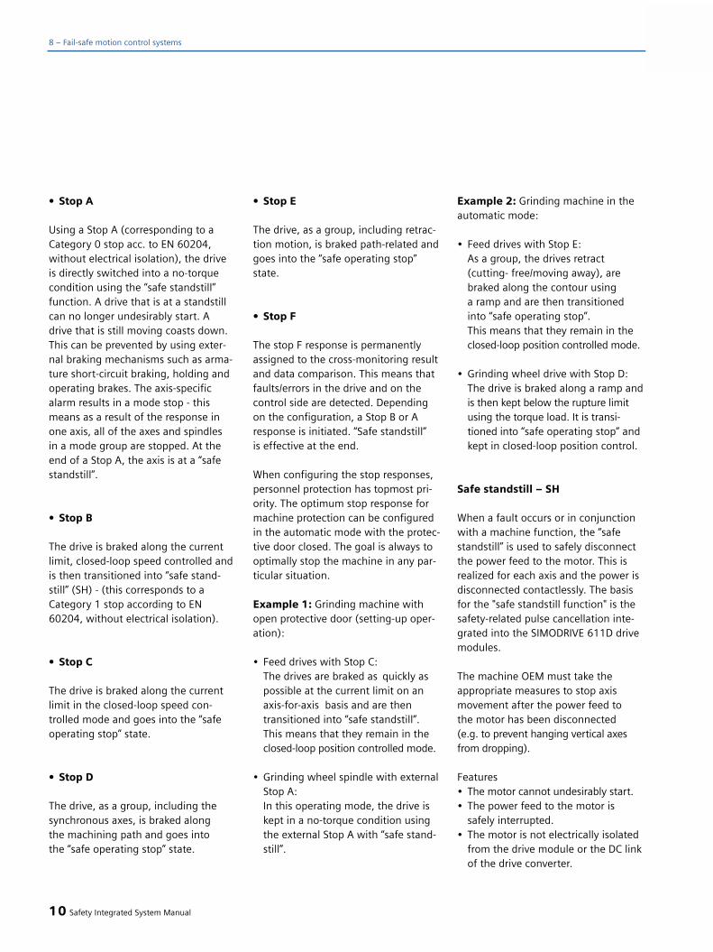
• Stop A
Using a Stop A (corresponding to aCategory 0 stop acc. to EN 60204,without electrical isolation), the driveis directly switched into a no-torquecondition using the “safe standstill”function. A drive that is at a standstillcan no longer undesirably start. A drive that is still moving coasts down.This can be prevented by using exter-nal braking mechanisms such as arma-ture short-circuit braking, holding andoperating brakes. The axis-specificalarm results in a mode stop - thismeans as a result of the response inone axis, all of the axes and spindles in a mode group are stopped. At theend of a Stop A, the axis is at a “safestandstill”.
• Stop B
The drive is braked along the currentlimit, closed-loop speed controlled andis then transitioned into “safe stand-still” (SH) - (this corresponds to aCategory 1 stop according to EN60204, without electrical isolation).
• Stop C
The drive is braked along the currentlimit in the closed-loop speed con-trolled mode and goes into the “safeoperating stop” state.
• Stop D
The drive, as a group, including thesynchronous axes, is braked along the machining path and goes into the “safe operating stop” state.
• Stop E
The drive, as a group, including retrac-tion motion, is braked path-related andgoes into the “safe operating stop”state.
• Stop F
The stop F response is permanentlyassigned to the cross-monitoring resultand data comparison. This means thatfaults/errors in the drive and on thecontrol side are detected. Dependingon the configuration, a Stop B or Aresponse is initiated. “Safe standstill” is effective at the end.
When configuring the stop responses,personnel protection has topmost pri-ority. The optimum stop response formachine protection can be configuredin the automatic mode with the protec-tive door closed. The goal is always tooptimally stop the machine in any par-ticular situation.
Example 1: Grinding machine withopen protective door (setting-up oper-ation):
• Feed drives with Stop C:The drives are braked as quickly as possible at the current limit on an axis-for-axis basis and are then transitioned into “safe standstill”. This means that they remain in the closed-loop position controlled mode.
• Grinding wheel spindle with externalStop A: In this operating mode, the drive iskept in a no-torque condition using the external Stop A with “safe stand-still”.
Example 2: Grinding machine in theautomatic mode:
• Feed drives with Stop E:As a group, the drives retract (cutting- free/moving away), arebraked along the contour using a ramp and are then transitioned into “safe operating stop”. This means that they remain in the closed-loop position controlled mode.
• Grinding wheel drive with Stop D:The drive is braked along a ramp and is then kept below the rupture limit using the torque load. It is transi-tioned into “safe operating stop” and kept in closed-loop position control.
Safe standstill – SH
When a fault occurs or in conjunctionwith a machine function, the “safestandstill” is used to safely disconnectthe power feed to the motor. This isrealized for each axis and the power isdisconnected contactlessly. The basisfor the "safe standstill function" is thesafety-related pulse cancellation inte-grated into the SIMODRIVE 611D drivemodules.
The machine OEM must take theappropriate measures to stop axismovement after the power feed to the motor has been disconnected (e.g. to prevent hanging vertical axesfrom dropping).
Features• The motor cannot undesirably start.• The power feed to the motor is
safely interrupted.• The motor is not electrically isolated
from the drive module or the DC linkof the drive converter.
10 Safety Integrated System Manual
8 – Fail-safe motion control systems
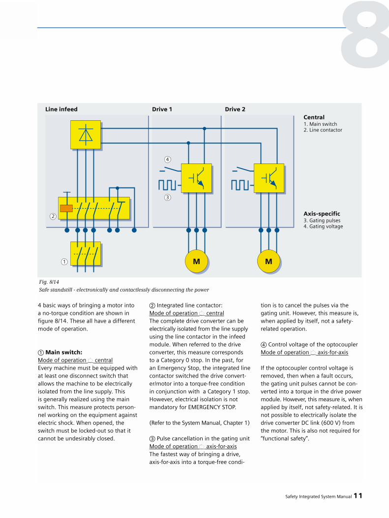
4 basic ways of bringing a motor into a no-torque condition are shown in figure 8/14. These all have a differentmode of operation.
a Main switch:Mode of operation w centralEvery machine must be equipped withat least one disconnect switch thatallows the machine to be electricallyisolated from the line supply. This is generally realized using the mainswitch. This measure protects person-nel working on the equipment againstelectric shock. When opened, theswitch must be locked-out so that itcannot be undesirably closed.
s Integrated line contactor:Mode of operation w centralThe complete drive converter can beelectrically isolated from the line supplyusing the line contactor in the infeedmodule. When referred to the driveconverter, this measure corresponds to a Category 0 stop. In the past, for an Emergency Stop, the integrated linecontactor switched the drive convert-er/motor into a torque-free condition in conjunction with a Category 1 stop.However, electrical isolation is notmandatory for EMERGENCY STOP.
(Refer to the System Manual, Chapter 1)
d Pulse cancellation in the gating unitMode of operation w axis-for-axisThe fastest way of bringing a drive,axis-for-axis into a torque-free condi-
tion is to cancel the pulses via thegating unit. However, this measure is,when applied by itself, not a safety-related operation.
f Control voltage of the optocouplerMode of operation w axis-for-axis
If the optocoupler control voltage isremoved, then when a fault occurs,the gating unit pulses cannot be con-verted into a torque in the drive powermodule. However, this measure is, whenapplied by itself, not safety-related. It isnot possible to electrically isolate thedrive converter DC link (600 V) fromthe motor. This is also not required for“functional safety”.
Safety Integrated System Manual 11
8
Fig. 8/14
Safe standstill - electronically and contactlessly disconnecting the power

Conclusion:
Measures 3 and 4 are physically de-coupled and together form an effectiveand safety-related method of cancelingthe drive converter pulses on an axis-for-axis basis. They form the basis for“safe standstill” and can be independ-ently initiated from the drive and theNC. The concept is rounded-off by in-tegrating it into cyclic tasks (forcedchecking procedure).
This means that a complete safety-related concept is created from individ-ual measures that completely fulfill therequirements for EMERGENCY STOP. It is no longer mandatory to open theline contactor.
However, when carrying-out work (e.g.service, maintenance...) on live com-ponents the equipment must alwaysbe electrically isolated from the linesupply.
Comment regarding EmergencyStop in the US
NFPA 79, the „Electrical Standard forIndustrial Machinery“ published by theNational Fire Protection Agency in theUS, war revised and has been in effectsince 2002. For the first time, appropri-ately qualified software, electronicsand bus communication systems arepermitted for Category 0 EmergencyStop. However, contrary to the EU forCategory 0 Emergency Stop, it as alsomandatory to subsequently electricallyisolate the safety-relevant equipmentfrom the line supply through electro-mechanical means. This requirementcan be engineered by the machine OEMas simply a supplement for the US ver-sion.
Safe operating stop - SBH
This function is used to safely monitorthe standstill position of an axis orspindle. In this case, the drives remainfully functional in the closed-loop posi-tion controlled or closed-loop speedcontrolled mode.
Features
• The axis remains in the closed-loop controlled mode.
• Parameterizable standstill tolerancewindow.
• Configurable stop responsewhen the monitoring responds(Stop B or A).
Safe braking ramp – SBR
With this function, the expectation thatafter a stop command, the actual velo-city must be reduced is used as basis(the speed characteristic is monitored).
When a stop command is initiated, thedisabled velocity plus a velocity toler-ance, specified using machine data, isactivated as velocity limit. This limit iscompared with the actual velocity(must be less than or remain the same)and is cyclically corrected. This means the system quickly detectsif the axis re-accelerates during brak-ing; a subsequent response is then ini-tiated.
Features
• The system quickly detects if the drive starts to accelerate while braking.
• The “safe braking ramp” is automa-tically activated if a stop B or C was initiated.
• A Stop A is directly initiated if the “safe braking ramp” is initiated.
Example, Emergency Stop
Safety-related signals and the requiredresponses are logically combined inter-nally using safety-related technology.The electric drives are safely stoppedand are then disconnected from thepower source via the electronics. Anundesirable restart is also safely pre-vented. External potentially hazardousenergy sources, for example, hydraulicsystems or lasers etc. can be disabledusing safety-related outputs associatedwith the integrated Emergency Stoplogic and downstream actuators (powercontactors, valves). The coordinatedsafe stopping process prevents or re-duces subsequent damage (e.g. crash)when shutting down and also permitsa fast, simple restart.
Test stop
Using the test stop, for each monitor-ing channel, the complete shutdownpath is tested with the external circuitry.
When executing the test, the compara-tors and stop modules of the two mon-itoring channels, which are responsiblefor the stop function, are executed oneafter the other. For more informationon the forced checking procedure, alsorefer to the Section “Forced checkingprocedure” for SINUMERIK SafetyIntegrated.
12 Safety Integrated System Manual
8 – Fail-safe motion control systems
Monitoring speed and position
Safely reduced speed - SG
The “safely reduced speed” function isused to safely monitor the speed of adrive.
To realize this, the actual speed of the drive is cyclically compared, in themonitoring clock cycle, with the speedlimit, selected via safety-related inputs.The speed limits are defined in themachine data.
Different applications and operatingstates at the machine can be moni-tored using the speed limit values forSG1, SG2, SG3 or SG4. Further, thelimit values safely-reduced speed 2 and safely-reduced speed 4 can begraded in 16 steps using “safety-rela-ted inputs” (4 bits). The entry is madeas a % (1 to 100%) and is saved in atable in the machine data. Thus, a total of 34 freely selectable speed li-mits are available for each drive. Thisallows personnel and machine protec-tion to be implemented in the setting-up mode and also in the automaticmode.
Comment: For changeover gearboxes,the correct gearbox ratio must be se-lected!
Features
• The load-side speed limit valuesare safely monitored.
• The monitored limit values can beadapted to various operating states(e.g. test, setting-up, automatic operation).
• Configurable, SG-specific stop responses.
Safely reduced speed-specific setpoint limiting
Using this function, for the first time,in addition to the speed actual value,the speed setpoint is also considered.The “safely reduced speed-specific set-point limiting” automatically limits thesetpoint to the currently effective limitof the safely reduced speed. If this valuechanges for a drive, then the setpointlimit is automatically corrected. If thedrives operate in a group, then thefunction acts on all of the coupleddrives. This means that the machinedcontour is always maintained.
Applications
• When testing NC programs(operating mode 3), e.g. when the protective door is open. Now, no test-specific changes have to be made to the program parameters.
• If a safety-related area is entered, e.g. using traversing keys, wherethe lower SG limit values are active,then the drive is not shut down, but instead is automatically reducedto the speed setpoint that is permis-sible there.
Features
• The setpoint limit actsin the NCK through 1-channel.
• Effective when traversing drives viatraversing keys or when NC programsare executed.
• The value of the limit lies beneath the active SG limit value by an adjustable percentage value.
• The axes involved are acceleratedor braked without any delay, inter-polating.
• The function is only executed if the programmed setpoint lies above the active SG limit value.
• If the programmed setpoint is less than the active SG limit value, then the drives traverse as specified in the program.
Safe software limit switch - SE
A working zone/protective zone demar-cation or traversing range limiting canbe implemented for each axis usingthis “safe software limit switch.” Thismeans, for example, that hardwarelimit switches are not required on themechanical system. Two limit switchpairs per axis are available. Each limitswitch pair consists of a positive switch(safe limit switch 1+ and safe limitswitch 2+) and a negative switch (safelimit switch 1– and safe limit switch2–). It is possible to toggle betweensafe limit switch 1 and safe limit switch2 using the safety-related inputs.
Safety Integrated System Manual 13
8

Features
• End positions are defined and evalu-ated per software in a safety-related fashion.
• Configurable stop response when passing end positions.
• The stop response when passingend positions is realized inside the software.
Safe software cam - SN
Safe range identification can be imple-mented for each axis using the safesoftware cam function. This meansthat today's “hardware solution” can be replaced
4 cam pairs (safe software cam 1 tosafe software cam 4) are available foreach axis. Each cam pair comprises apositive cam (safe software cams 1+,2+, 3+ and 4+) and a negative cam(safe software cams 1–, 2–, 3– and4–). Each cam signal can be individual-ly configured via the machine data.The cam signals are output via safety-related outputs.
Features
• Cam positions can be safely defined and evaluated using software.
• Safety ranges are defined.
• SN dependent, safety changeoverof safety-related functions (e.g. safety-related changeover/selection of SG stages dependent on the actual position).
Logically combining safety-related process signals
Safe programmable logic - SPL
The “safe programmable logic” allows,for the first time, safety-related sensorsand actuators to be directly connectedand logically combined. The logic isredundantly incorporated in the NCand in the internal PLC. This meansthat all safety-related sensors and actu-ators, e.g. Emergency Stop or inter-locking concepts for protective doorscan be configured using the SINU-MERIK Safety Integrated software. Inconjunction with “safe standstill”, theEmergency Stop can now be imple-mented in the evaluation logic up tothe power disconnection contactlesslyand using safety-related technology.
Discrete hardware contacts can beeliminated which is reflected in a sim-plified cabinet design. Only the powercontacts (e.g. contactors) are requiredto directly control the external actuators.
Features
• Universal, programmable logic in safety-related technology
• The logic is immediately activated after run-up
• Cyclic sequence independent ofthe user program
• Integrated timer for the forcedchecking procedure
• Effective in all operating modes.
14 Safety Integrated System Manual
8 – Fail-safe motion control systems
Fig. 8/15
Basic structure - safe programmable logic
Safety-related I/O - SGE/SGA
The safety-related input and outputsignals represent the interface to theprocess. They are digital signals thatare entered into the system or are output from the system through twochannels. The safety-related inputs and outputs need not be routed viahardware terminals.
In conjunction with the safe program-mable logic, when required, they canbe internally processed as softwaresignal.
Features
• Safety functions can be selected and de-selected
• Limit values can be selected and changed-over
• Status signals can be fed back
• Cam signals can be output
• Sensors can be directly connected
• Actuators can be directly connected.
Vertical axes are protectedfrom dropping
General requirements
When drives are shut down, axes ormechanical assemblies can drop due to the force of gravity. For verticallinear axes (hanging/suspended axes)or for rotary axes or spindles with anon-symmetrical weight distribution,this can result in potentially hazardousmotion. This is the reason that theseaxes or mechanical assemblies mustbe safely kept at a standstill using suit-able measures. Measures to achieve thiscan include, for example:
a) Temporarily activeHolding brakesOperating brakesElectric drives
b) Continuously activeMechanical weight equalization
c) Active in exceptional casesPinsVarious types of supports
The measure or measures which is/areselected depends on the type of workwhich is to be carried-out in the dan-gerous area. Is work to be directly car-ried-out under a suspended load oronly close to it? Also the time spent in the dangerous area must be takeninto account in the design phase asthis may make it necessary to combineseveral measures. The hazardous ana-lysis is always the basis for this andmust be carried-out for each and everymachine. The overall concept must be
designed so that it fulfills the require-ments for personnel protection accord-ing to the EEC Machinery Directive andall other applicable standards anddirectives.
Comment:
When carrying-out work on live partsand components (with the exceptionof safety extra-low voltage), electricalisolation from the line supply is alwaysrequired.
Requirements from the GermanTrade Association data sheet (EM II, Mainz)
The requirements placed on machineswith the appropriate hazard potentialare described in this data sheet.
Here are some of the most importantrequirements as excerpt:
• Safety-related, redundant holdingsystem in order to prevent verticalaxes dropping"
• Testing mechanical brakes(control category 2 acc. toEN 954-1)
• Protection to prevent electricdrive unintentionally/accidentally restarting (control category 3 acc. to EN 954-1)
• Acceptance test using a form
The actual document is available in the Internet underwww.smbg.de/Sites/downloads/005-MFS-A04_Vertikalachsen.pdf
Safety Integrated System Manual 15
8

Concept to prevent verticalaxes dropping
The existing systems, electric drive andmechanical brake form, together, thesafety-related, redundant holding sys-tem. The safety concept of SINUMERIKSafety Integrated integrates these stan-dard components so that their effect issafety-related.
1.Safety-related drive achievedby applying safety functions, e.g.:• “Safe standstill”• “Safe operating stop”• “Safely reduced speed”
2.Safe braking function achievedusing the “safety relevant brake management” with the sub-functions:• “Safe brake control”• “Safe brake test”
The safe drive forms the 1st holdingsystem and is the main holding systemelement - the mechanical brake forms,as safety-related brake function, the2nd holding system and is (open) inthe standby mode.
When the drive fails, the brake is auto-matically and safely activated andassumes the function of holding themechanical system. It is not absolutelynecessary to use a second brake.This means that for the first time thereis an extensive and integrated solutionregarding “ preventing vertical axesdropping" as well as rotary axes andspindles with non-symmetrical weightdistribution.
The risk when working with hanging/suspended loads is, using this func-tionality, significantly reduced andtherefore provides an additional role in
protecting personnel. Not only this,machine damage as a result of drop-ping axes is essentially avoided and the availability of machines and sys-tems increased.
Depending on the particular require-ment, the safe redundant holding sys-tem can be used in the following appli-cations:
1.The drive is active if the brake isopen and is in the standby mode
Objective: Minimize the sagto < 25 mm• The drive can move or remain
stationary• The brake automatically and safely
closes as soon as the drive failse.g. due to a system-fault.
Result:Depending on the speed, direction ofmotion, system response time, brakeclosing time and friction in the mecha-nical system, then the vertical axis sags(drops) - which cannot be avoided.
2.The drive and the brake aresimultaneously active (drive with adapted control parameters / filters)
Objective: Minimize the sag to < 1 mm• The drive is stationary, the brake
is closed• A signal is automatically output
as soon as one of the two holdingsystems fails
• Now, the holding system that is stillintact, only holds the mechanical system
16 Safety Integrated System Manual
8 – Fail-safe motion control systems
Fig. 8/16
Protection against vertical axes dropping

Result:The vertical axis does not drop anysignificant distance that would be relevant for personnel protection.
Comments:
• Acceptance reportThe amount of sag should be measured and documented in the acceptance report!
• When the drives are shut downfor operational reasons
The drive is operationally shut downindependent of any system faults - e.g.for an Emergency Stop. In this case,the brake is closed before the drive isshut down and the vertical axis ismechanically clamped. This involves aspecific operation which means thatthe vertical axis does not drop any sig-nificant distance that would be rele-vant for personnel protection (< 1 mm).
Safe brake management - SBM
The reliability of a mechanical brake is asignificant component when protectingvertical axes from dropping. Analyses ofaccidents indicated that both faults inthe control as well as in the mechanicalsystem of the brake were responsiblefor vertical axes dropping. The analysisalso indicated that these accidentscould have been avoided by using safe-ty technology.
With this as background, we are offer-ing our customers a solution with “safebrake management”.
“Safe brake management” (SBM)comprises two function elements:
1. Safe brake control (SBC)
2. Safe brake test (SBT)
Brakes which are generally used todayare not safety-related components. By integrating the standard brake (a component proven in operation) in the safety concept of SINUMERIKSafety Integrated, a safe brake func-tion is obtained.
The brake is safely controlled and issubject to a forced checking procedure.Extended test measures are required as there is no feedback signal for theholding torque. The safe brake test can fulfill this requirement. Faults inthe control and in the brake mechani-cal system can be detected using theextended test measures.
Depending on the result of the hazard analysis, there are various ways of mounting the brake:
1.A brake in the motor,transmission elementswith overload factor > 2 (BG EM II, Mainz) [German Regulatory body]
2. A brake connected to the loadtransmission elements with overload factor < 2
3. A brake in the motor - special requirement and a brake connected to the load
In case of doubt, the preferred solutionis to mount the brake at the load, e.g.on the linear guide instead of mount-ing it in or on the motor.
Safe brake control
The brake (operating or holding brake)is, in control Category 3 (acc. to EN954-1) safely and electrically controlled.The control is realized through twochannels (P/M switching) with:
• Safety-related outputs with separate PLC and NC hardware
• Fail-safe outputs of the F-DO in ET 200S PROFIsafe
Using these two versions, it is possibleto detect faults on the control lines, for example, short-circuits, brokencable etc. Even if a channel fails, thebrake can still be controlled.
Comment:
Intermediate relay stages increase theresponse time when controlling thebrake - this increases the distance thatthe vertical axis drops. This is the rea-son, if possible, that a direct electroniccontrol is preferred. This is possible upto 2 A.
Safety Integrated System Manual 17
8
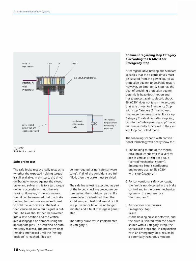
Safe brake test
The safe brake test cyclically tests as towhether the expected holding torqueis still available. In this case, the drivedeliberately moves against the closedbrake and subjects this to a test torque- when successful without the axismoving. However, if the axis moves,then it can be assumed that the brakeholding torque is no longer sufficientto hold the vertical axis. The test isthen canceled and a fault signal is out-put. The axis should then be traversedinto a safe position and the verticalaxis disengaged or clamped using theappropriate pins. This can also be auto-matically realized. The protective doorremains interlocked until the “restingposition” is reached. This can
be interrogated using “safe softwarecams”. If all of the conditions are ful-filled, then the brake must serviced.
The safe brake test is executed as partof the forced checking procedure be-fore testing the shutdown paths. If abrake defect is identified, then theshutdown path test that would resultin a pulse cancellation, is no longerinitiated and a fault message is gener-ated.
The safety brake test is implemented in Category 2.
Comment regarding stop Category1 according to EN 60204 forEmergency Stop
After regenerative braking, the Standardspecifies that the electric drives mustbe isolated from the power source asprotection against undesirable restart.However, an Emergency Stop has thegoal of providing protection againstpotentially hazardous motion and not to protect against electric shock.EN 60204 does not taken into accountthat safe drives for Emergency Stopwith stop Category 2 must at leastguarantee the same quality. For a stopCategory 2, safe drives after stopping,go into the “safe operating stop” modeand remain fully functional in the clo-sed-loop controlled mode.
The following scenario with conven-tional technology will clearly show this:
1.The holding torque of the mecha-nical brake connected to a vertical axis is zero as a result of a fault (control/mechanical system). Emergency Stop is configured/engineered acc. to EN 60204 with stop Category 1.
2.For conventional safety concepts, the fault is not detected in the brake control and in the brake mechanical system – this represents a “dormant fault”.
3.An operator now pressesEmergency Stop!Result: As the holding brake is defective, andthe drive is isolated from the power source with a Category 1stop, the vertical axis drops and, in conjunction with an Emergency Stop, results in a potentially hazardous motion!
18 Safety Integrated System Manual
8 – Fail-safe motion control systems
Fig. 8/17Safe brake control

Here is the same scenario using safedrives
1.The holding torque of the mechanicalholding brake at a vertical axis is zero due to a mechanical fault (a fault in the brake control is directly detected,and the brake is closed via the secondchannel). The Emergency Stop is configuredacc. to EN 60204 with a Category 1 stop.
2.The fault is detected by the braketest. An appropriate fault signal is displayed. The protective door remains interlocked, and the axis must be moved to a safe position.
3.An operator now presses theEmergency Stop before reachingthe safe position!Result:In spite of the fact that the EmergencyStop has been activated, the drive with the defective brake is not isola-ted from the power source, but safely stopped and then is safely monitoredat standstill using the safe operating stop. No hazardous motion-occurs.
Integrated and partially-automated acceptancereport
For every drive control, the system be-havior is adapted to the requirementsof the particular machine using param-eters that can be set. For instance, themaximum permissible speeds or thebraking characteristics when stoppinga drive are defined. In so doing, whenconfiguring/engineering the system orwhen entering parameters via a PC or a programming device, errors can bemade. This is the reason that as part of commissioning procedure, all of thesafety functions of electric drive sys-tems should be tested and document-ed in the form of a machine acceptancetest. This must be done independentlyof whether safety functions are imple-mented using control systems with
integrated safety or using externalmonitoring equipment and devices.
A differentiation is made between acomplete and a partial acceptance test.With a complete acceptance test, all of the safety functions provided (e.g.maintaining limit values, functions ofcommand transmitters/sensors, func-tions of actuators) must be carefullychecked. With this test, the completefault response chain - from the sensorthrough the control up to the actuator- is run-through and the safety func-tions carefully checked in order toensure that they operate correctly. This applies for all electric drive systemsin machines. For a partial acceptancetest, only the safety-related parametersmust be tested that were changed withrespect to the complete acceptance test,or have been added.
Safety Integrated System Manual 19
8
Fig. 8/18Acceptance test for the safe operating stop

With the integrated acceptance test,the machinery construction OEM hasan operator prompted tool that can beused semi-automatically carry out thistest. In so doing, the required tracefunctions are automatically configured.The automatically generated accept-ance test report certifies the testedfunctional safety of the machine –both for the machinery constructionOEM as well as the end user actuallyoperating the machines. The time sav-ing that can be achieved with a promp-ted acceptance test is quite significant.
20 Safety Integrated System Manual
8 – Fail-safe motion control systems
Fig. 8/19Setpoint velocity
Fig. 8/20Actual position

Forced checking procedurefor SINUMERIK Safety Integrated
The forced checking procedure is usedto detect faults in the software andhardware of the two monitoring chan-nels. In this case, the safety-relatedcomponents in the two channels mustbe processed at least once within adefined time period and in all safety-related branches. A fault in a monitor-ing channel results in deviations and is detected by the crosswise data andresult comparison.
The user must initiate the forcedchecking procedure of the shutdownpath (test stop) or it must be automa-tically integrated into the process - forexample:
• With the axes stationary afterpowering-up the system
• When opening the protective door
• In a specified cycle (e.g. every 8 hours)
• In the automatic mode - dependent on the time and the event
The forced checking procedure alsoincludes testing safety-related sensorsand actuators. In this case, the com-plete signal chain, including the “safeprogrammable logic” is checked toensure that it is functioning correctly.
Safety Integrated System Manual 21
8
Fig. 8/21Actual velocity
Fig. 8/22Acceptance test certificate

Comment:
For the duration of automatic operation(with the protective door closed), thefixed 8-hour cycle isn't mandatory. Inthis case, the forced checking proce-dure can be logically combined, after 8 hours have expired, the next timethat the protective door is opened. Asa result of the crosswise comparison,errors are detected in the safety-relateddata of the two monitoring channels.For “changing” data, there are toler-ance values specified by the machinedata. The results of the two channelscan deviate within these toleranceswithout a response being initiated. An example is the tolerance for cross-wise comparison of the actual posi-tions. Faults that are detected due tothe forced checking procedure and thecrosswise data comparison result in astop F response and this initiates addi-tional strop responses (refer to the sec-tion “Stop responses”).
Connecting sensors/actua-tors - basics
In order to integrate sensors and actua-tors in a safety-related fashion, theirprocess signals must be fed to the “safeprogrammable logic” SPL for furtherprocessing.
The following connection types areavailable:
1.Via separate PLC and NC hardware in degree of protection IP20
2.Via PROFIsafe with the ET 200S-PROFIsafe I/O modules with degree of protection IP20
3.Via PROFIsafe as direct, safe com-munications with a safety-related PROFIsafe sensor / actuator
This applies for process signals from:
• Sensors, e.g. switches, protectivedoor contacts, Emergency Stoppushbuttons, light curtains, laser scanners
• Actuators, e.g. load contactors, valves, interlocking solenoids, brakes
These are directly connected withoutusing any external evaluation devicesand transferred to the “SINUMERIKSafety Integrated” platform.
Comments regarding the mechani-cal sensor design
A differentiation should be madebetween the following cases:
1.The sensor (e.g. protective doorinterlocking) is a safety-relatedcomponent and is certified. This means that faults can be excluded - and no additional measures are required.
2.The sensor is an operationally-proven component acc. to EN 954-2.Faults can be excluded under the following conditions:
• Regular maintenance is carried-out according to the manufactur-er's specifications
• Sensors are regularly replacedafter the product lifetimehas expired
• Faults are detected by the down-stream electronics and cyclic tests as a result of updates carried-out by the process (e.g. protective door),or as a result of the forced-checkingprocedure.
3.The sensor is not an operationally-proven component acc. to EN 954-2.A fault cannot be excluded.
• The two elements issuing the signal (e.g. switching contacts ofa pushbutton) of the sensor must be mechanically de-coupled – or two separate sensors are used.
• Faults are detected using the down-stream electronics with cyclic tests using dynamic update by the pro-cess (e.g. protective door), or using a forced checking procedure.
22 Safety Integrated System Manual
8 – Fail-safe motion control systems

Comments on the mechanicalactuator design
A differentiation should be madebetween the following cases:
4.The actuator (e.g. safety-related motor starter) is a safety componentand has been certified. This means that a fault situation can be excluded- no additional measures are required.
5.The actuator is a component, whichhas been well-proven in operation, in accordance with EN 954-2 (e.g. a valve)A fault can be excluded under the following conditions:
• Regular maintenance is carried-out according to the manufacturer's specifications
• An actuator is replaced after its product lifetime has expired
• Faults are detected using the feedback signal from the processand cyclic tests using dynamicupdates by the process or the forced-checking procedure.
6.The actuator is a standard componentFaults cannot be excluded.
• Two separate mechanically de-coupled actuators are required.
• Faults are detected using the feedback signal from the processand cyclic tests using dynamicupdates by the process or the forced-checking procedure.
Safety Integrated System Manual 23
8
Fig. 8/23Connecting sensors/actuators through S7 I/O and the DMP module of the NC
Fig. 8/24 Connecting sensors/actuators through ET 200S PROFIsafe
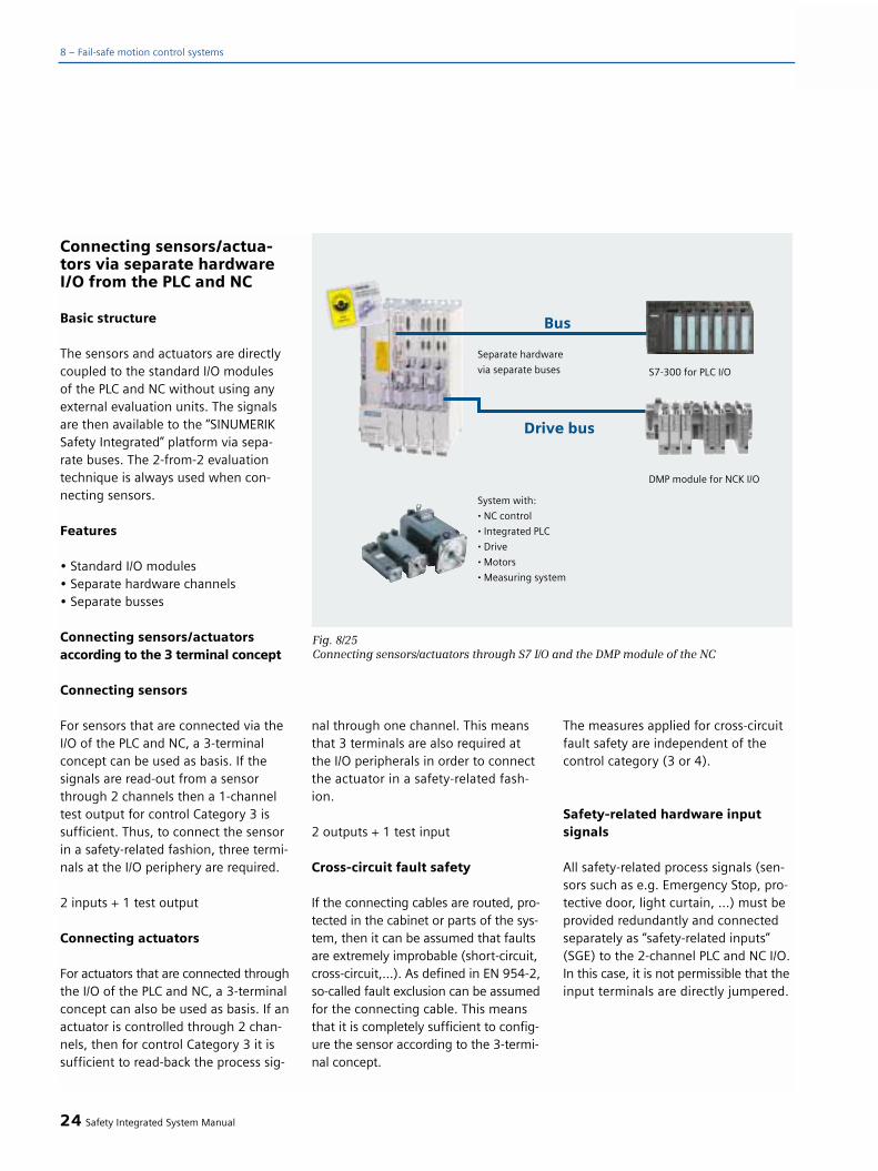
Connecting sensors/actua-tors via separate hardwareI/O from the PLC and NC
Basic structure
The sensors and actuators are directlycoupled to the standard I/O modules of the PLC and NC without using anyexternal evaluation units. The signalsare then available to the “SINUMERIKSafety Integrated” platform via sepa-rate buses. The 2-from-2 evaluationtechnique is always used when con-necting sensors.
Features
• Standard I/O modules• Separate hardware channels• Separate busses
Connecting sensors/actuatorsaccording to the 3 terminal concept
Connecting sensors
For sensors that are connected via theI/O of the PLC and NC, a 3-terminalconcept can be used as basis. If thesignals are read-out from a sensorthrough 2 channels then a 1-channeltest output for control Category 3 issufficient. Thus, to connect the sensorin a safety-related fashion, three termi-nals at the I/O periphery are required.
2 inputs + 1 test output
Connecting actuators
For actuators that are connected throughthe I/O of the PLC and NC, a 3-terminalconcept can also be used as basis. If anactuator is controlled through 2 chan-nels, then for control Category 3 it is sufficient to read-back the process sig-
nal through one channel. This meansthat 3 terminals are also required atthe I/O peripherals in order to connectthe actuator in a safety-related fash-ion.
2 outputs + 1 test input
Cross-circuit fault safety
If the connecting cables are routed, pro-tected in the cabinet or parts of the sys-tem, then it can be assumed that faultsare extremely improbable (short-circuit,cross-circuit,...). As defined in EN 954-2,so-called fault exclusion can be assumedfor the connecting cable. This meansthat it is completely sufficient to config-ure the sensor according to the 3-termi-nal concept.
The measures applied for cross-circuitfault safety are independent of thecontrol category (3 or 4).
Safety-related hardware inputsignals
All safety-related process signals (sen-sors such as e.g. Emergency Stop, pro-tective door, light curtain, ...) must beprovided redundantly and connectedseparately as “safety-related inputs”(SGE) to the 2-channel PLC and NC I/O.In this case, it is not permissible that theinput terminals are directly jumpered.
24 Safety Integrated System Manual
8 – Fail-safe motion control systems
Fig. 8/25Connecting sensors/actuators through S7 I/O and the DMP module of the NC

Application example: EmergencyStop
Features
• The sensor is controlled with 24 V from a PLC test output through a common connection and fed to the safety-related control via the two input channels 1 and 2.
• In conjunction with the crosswisedata comparison and the forcedchecking procedure, faults (P andM short circuit) can be detectedin the connecting cables.
• A pure cross-circuit fault between the two inputs of channel and 1 and 2 cannot be detected using the 3-terminal concept.
It must be ensured that the signal stateof the “safety-related inputs” does notdiffer. Depending on the tolerance timer(approx. < 1 sec.) when the tolerancetime is exceeded, a monitoring func-tion responds and the machine is auto-matically shut down.
Comment 1:
For sensors that offer just pure elec-tronic outputs - i.e. no contacts - thatto some extent is possible for lightcurtains - the external circuit at the PLC and NC inputs remains the same.However, the test output of the PLC is directly connected to the special test input at the sensor. The 3-terminalconcept is essentially kept.
Comment 2:
If a safety component (e.g. EmergencyStop button) is not used as sensor, thenthe two signal-generating elements(e.g. switching contacts for a pushbut-ton) must be mechanically de-coupled.
Connecting sensors acc. tothe 4-terminal concept
If connecting cables cannot be com-pletely protected against crushing (e.g. cables used to connect handheld/programming terminals), or if higherrequirements apply as a result of theapplication, then a pure cross-circuit(no P or M short-circuit) must beassumed in the hazard analysis. Thismeans that the sensor must be con-nected using the 4-terminal concept.In this case, two separate cables areconnected to the two signal-generat-ing elements (e.g. contacts). 4 termi-nals are required at the I/O peripheryto integrate the sensor in a safety-related fashion.
2 inputs + 2 test outputs
Cross-circuit fault safety
Using this technique, with standardmodules, it is possible to implementcomplete fault detection functionalityfor the sensor connecting cables. Theconnecting cables do not have to berouted in any special way.
Safety-related hardware inputsignals
The basic principle corresponds to thatof the 3-terminal concept. The extend-ed measures are designed to detect apure cross-circuit fault (i.e. no connec-tion to M or P potential) between thetwo cables.
Safety Integrated System Manual 25
8
Fig. 8/26Connecting sensors using the 3-terminal concept – using Emergency Stop as an example

Application example: EmergencyStop
Features
• The sensor is directly controlledwith 24 V from each of the 2 PLC test outputs and fed to the safety-related control via the two input channels 1 and 2.
• Test output 1 is delayed by tx with respect to test output 2. The expect-ed response is a clear, unique signal characteristic at input channels 1/2.
• A 1-channel test routine in the PLC tests this expected response. This test can be carried-out as part of the forced checking procedure.
• In conjunction with the crosswise data comparison and the forced checking procedure, all faults (P and M short-circuit) incl. a pure cross-circuit fault can be detected in the connecting cables.
Comment 1:
The concept presented here can onlybe used with sensors using contactsand in closed circuits (closed-circuitprinciple). For electronic signals, thesensor must implement the cable mon-itoring function.
Comment 2:
If a safety component (e.g. EmergencyStop button) is not used as sensor,then the two signal-generating ele-ments (e.g. switching contacts for apushbutton) must be mechanically de-coupled.
Safety-related hardware outputsignals - P/P switching
For P/P switching versions, two actua-tors are always switched in series inthe load circuit. Both channels (NC and PLC) control the actuators with apositive potential (24 V) (positive-posi-tive switching). Commercially availablecontactors with positively-driven feed-back signal contacts can be used, forexample to control motors.
The feedback signal from the load cir-cuit should be derived as directly aspossible from the process quantity. For example, a direct feedback signalof the hydraulic pressure supplied froma pressure sensor or a feedback signalfrom the moved mechanical system
(endstop) using a Bero is preferredover an indirect feedback signal fromthe hydraulic valve.
26 Safety Integrated System Manual
8 – Fail-safe motion control systems
Fig. 8/27Connecting sensors using the 4-terminal concept – using Emergency Stop as an example
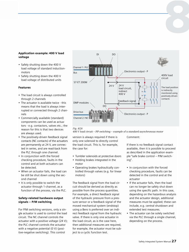
Application example: 400 V loadvoltage
• Safely shutting down the 400 V load voltage of standard induction-motors
• Safely shutting down the 400 V load voltage of distributed units
Features
• The load circuit is always controlled through 2 channels
• The actuator is available twice - this means that the load is always inter-rupted or connected through 2 chan-nels
• Commercially available (standard)components can be used as actua-tors - e.g. contactors, valves etc.; thereason for this is that two devices are always used.
• The positively-driven feedback signalcontacts (NC contacts) of the actuatorsare permanently at 24 V, are connec-ted in series, and are read-back from the PLC through one channel.
• In conjunction with the forcedchecking procedure, faults in thecontrol and at both actuators can be detected.
• When an actuator fails, the load can be still be shut down using the sec-ond channel
• It is only possible to switch theactuator through 1-channel, as a function of the process, via the PLC.
Safety-related hardware outputsignals – P/M switching
For P/M switching versions, only a sin-gle actuator is used to control the loadcircuit. The NC channel controls theactuator with a positive voltage (24 V);the PLC channel controls the actuatorwith a negative potential (0 V) (posi-tive-negative switching). This control
version is always required if there isonly one solenoid to directly controlthe load circuit. This is, for example,the case for:
• Tumbler solenoids at protective doors• Holding brakes integrated in the
motor• Operating brakes hydraulically con-
trolled through valves (e.g. for linear motors)
The feedback signal from the load cir-cuit should be derived as directly aspossible from the process quantities.For example, a direct feedback signalof the hydraulic pressure from a pres-sure sensor or a feedback signal of themoved mechanical system (endstop)using a Bero is preferred over an indi-rect feedback signal from the hydraulicvalve. If there is only one actuator inthe load circuit, as is the case here,then additional measures are required,for example, the actuator must be sub-ject to a cyclic function test.
Comment:
If there is no feedback signal contactavailable, then it is possible to proceedas described in the application exam-ple “safe brake control – P/M switch-ing”.
• In conjunction with the forcedchecking procedure, faults can bedetected in the control and at the actuator
• If the actuator fails, then the load can no longer be safely shut down using the specific path. In this case, depending on the hazardous analysisand the actuator design, additional measures must be applied; these caninclude, e.g. central shutdown and extended test measures.
• The actuator can be solely switchedvia the PLC through a single channel,depending on the process.
Safety Integrated System Manual 27
8
Fig. 8/28400 V load circuit – P/P switching – example of a standard asynchronous motor
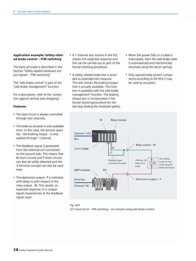
Application example: Safety-relat-ed brake control – P/M switching
The basic principle is described in theSection “Safety-related hardware out-put signals – P/M switching”.
The “safe brake control” is part of the“safe brake management” function.
For a description, refer to the “protec-tion against vertical axes dropping".
Features
• The load circuit is always controlledthrough two channels.
• The brake as actuator is only availableonce. In this case, the process quan-tity - the braking torque - is only applied through 1 channel.
• The feedback signal is generatedfrom the solenoid coil connectionon the ground side. This means thatM short circuits and P short circuitscan also be safely detected and the 3-terminal concept can also be used here.
• The electronics output - P is switched,with delay tx with respect to the relay output - M. This results, as expected response, in a unique signal characteristic at the feedback signal input.
• A 1-channel test routine in the PLC checks this expected response and this can be carried-out as part of theforced checking procedure.
• A safety-related brake test is provi-ded as extended test measure.This test checks the braking torquethat is actually available. This func-tion is available with the safe brakemanagement" function. The brakingtorque test is incorporated in the forced checkingprocedure for the test stop (testing the shutdown paths).
• When the power fails or a cable is interrupted, then the safe brake stateis automatically and mechanically assumed using the return springs.
• Only operationally-proven compo-nents according to EN 954-2 may be used as actuators.
28 Safety Integrated System Manual
8 – Fail-safe motion control systems
Fig. 8/29
24 V load circuit – P/M switching – an example using safe brake control

Safety-related hardware outputsignals – P/M switching with inter-mediate relay stage
With this example, contrary to the pre-viously described direct P/M switchingversion, the load circuit is controlledthrough an additional intermediaterelay stage to amplify the current. Theintermediate relay stage must be usedif there is no 2 A output module of theNC I/O and/or no S7 relay module avail-able or if the load current to be switchedis > 2 A.
The outputs used in the NC and PLCare standard outputs where the inter-mediate relay stage is switched P/P.
Caution!
When using the intermediate relaystage, when compared to the best case(fast, contact-free NC path switching),the response time is extended by therelay switching time. This results inlonger response times which in turnmeans that the axes drop further (sag)when faults develop.
Application example: 24 V loadvoltage > 2 A
• Load power supply from distributed units with > 2 A
• Brakes with > 2 A
Features
• Principally, the same features apply as for the direct P/M switching con-trol.
• The control in the 24 V load circuitremains as already shown in Fig. 8/30: “24 V load circuit – P/M switch-ing up to 2 A and up to 10A” - P/M switching.
• It is not absolutely necessary to incorporate the positively-drivenfeedback signal contacts of the intermediate relay stage. This means that standard relays can be used
without positively-driven feedback signal contacts. However, in this case, the direct feedback signal fromthe M potential of the load circuitmust be directly connected.
• Incorrect functions in the load circuit path are detected by the direct feedback signal from the M potential, e.g. – When the relay does not switch/
drop-out (e.g. due to welded contacts, relay contacts caught)
– Short-circuits on the 24 V controllines and the load circuit.
Safety Integrated System Manual 29
8
Fig. 8/30
24 V load circuit – P/M switching with intermediate relay stage for > 2 A
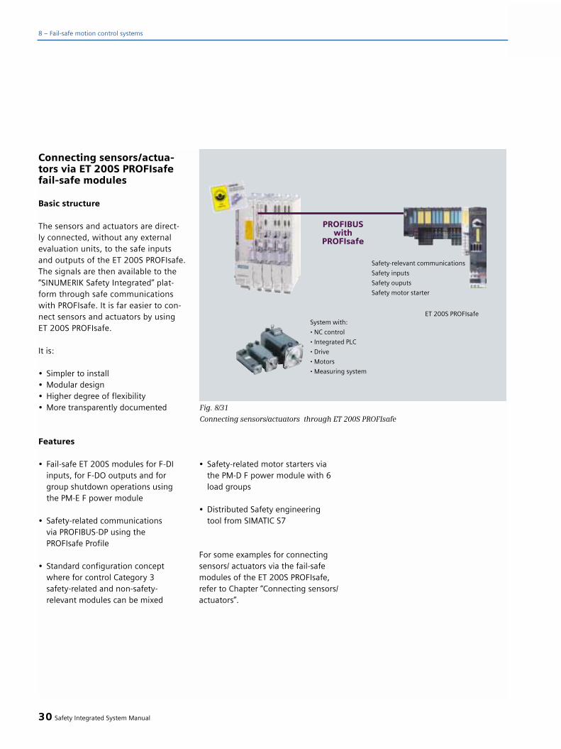
Connecting sensors/actua-tors via ET 200S PROFIsafefail-safe modules
Basic structure
The sensors and actuators are direct-ly connected, without any externalevaluation units, to the safe inputs and outputs of the ET 200S PROFIsafe.The signals are then available to the“SINUMERIK Safety Integrated” plat-form through safe communicationswith PROFIsafe. It is far easier to con-nect sensors and actuators by usingET 200S PROFIsafe.
It is:
• Simpler to install• Modular design• Higher degree of flexibility• More transparently documented
Features
• Fail-safe ET 200S modules for F-DI inputs, for F-DO outputs and for group shutdown operations using the PM-E F power module
• Safety-related communicationsvia PROFIBUS-DP using the PROFIsafe Profile
• Standard configuration conceptwhere for control Category 3 safety-related and non-safety-relevant modules can be mixed
• Safety-related motor starters viathe PM-D F power module with 6 load groups
• Distributed Safety engineeringtool from SIMATIC S7
For some examples for connectingsensors/ actuators via the fail-safemodules of the ET 200S PROFIsafe,refer to Chapter “Connecting sensors/actuators”.
30 Safety Integrated System Manual
8 – Fail-safe motion control systems
Fig. 8/31
Connecting sensors/actuators through ET 200S PROFIsafe
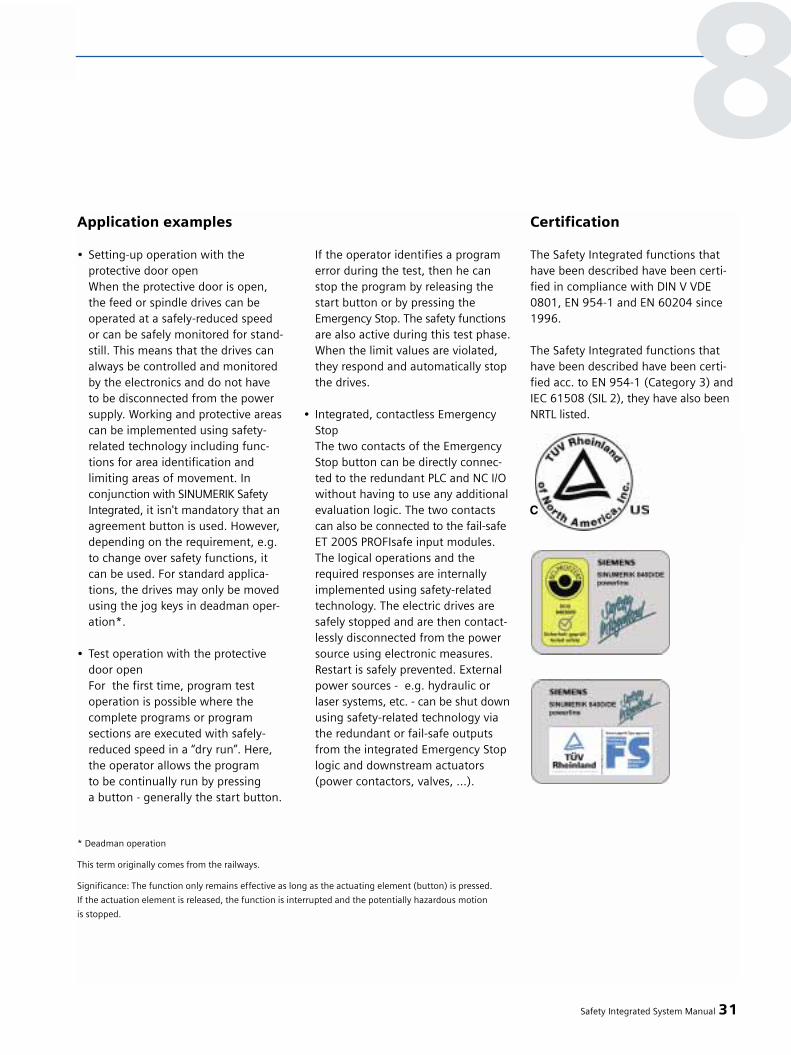
Application examples
• Setting-up operation with theprotective door openWhen the protective door is open,the feed or spindle drives can beoperated at a safely-reduced speedor can be safely monitored for stand-still. This means that the drives can always be controlled and monitored by the electronics and do not have to be disconnected from the power supply. Working and protective areascan be implemented using safety-related technology including func-tions for area identification and limiting areas of movement. In conjunction with SINUMERIK Safety Integrated, it isn't mandatory that an agreement button is used. However, depending on the requirement, e.g. to change over safety functions, it can be used. For standard applica-tions, the drives may only be moved using the jog keys in deadman oper-ation*.
• Test operation with the protective door open For the first time, program test operation is possible where thecomplete programs or programsections are executed with safely-reduced speed in a “dry run”. Here, the operator allows the program to be continually run by pressing a button - generally the start button.
If the operator identifies a program error during the test, then he can stop the program by releasing the start button or by pressing the Emergency Stop. The safety functions are also active during this test phase.When the limit values are violated, they respond and automatically stop the drives.
• Integrated, contactless Emergency StopThe two contacts of the Emergency Stop button can be directly connec-ted to the redundant PLC and NC I/O without having to use any additionalevaluation logic. The two contacts can also be connected to the fail-safe ET 200S PROFIsafe input modules. The logical operations and the required responses are internally implemented using safety-related technology. The electric drives are safely stopped and are then contact-lessly disconnected from the power source using electronic measures. Restart is safely prevented. External power sources - e.g. hydraulic or laser systems, etc. - can be shut downusing safety-related technology via the redundant or fail-safe outputsfrom the integrated Emergency Stop logic and downstream actuators (power contactors, valves, ...).
Certification
The Safety Integrated functions thathave been described have been certi-fied in compliance with DIN V VDE0801, EN 954-1 and EN 60204 since1996.
The Safety Integrated functions thathave been described have been certi-fied acc. to EN 954-1 (Category 3) andIEC 61508 (SIL 2), they have also beenNRTL listed.
Safety Integrated System Manual 31
8
* Deadman operation
This term originally comes from the railways.
Significance: The function only remains effective as long as the actuating element (button) is pressed.
If the actuation element is released, the function is interrupted and the potentially hazardous motion
is stopped.

The safety package for metalforming technology
Measures have to be applied to all pro-duction machines - especially on press-es - to protect the operating personnel.These measures eliminate any poten-tial hazards in the operating process.This can be realized by securing ma-chines using protective doors or lightgrids. However, if operators must fre-quently intervene in the operationalproduction process, then the machineresponses must be monitored, e.g.using speed monitoring functions. This avoids hazardous machine motionfor fault-related failures at the controland mechanical system.
The Safety Unit TM 121 was developedto cover such requirements.
It has been designed so that the fol-lowing safety requirements are ful-filled:
• EN 954-1 safety-related parts of controls. Here, the unit is in compliance with Category 4.
• IEC 61508 Functional Safety of electrical/electronic/programmable safety-related systemsIn this case, the unit is in compliancewith SIL 3.
• EN 61496 Safety of Machinery, contactless (electro-sensitive) protective devices and equipment
Excerpts from this have been takeninto account, i.e. a higher severitylevel, e.g. for mechanical loads or EMC.
This means that the prerequisites toimplement safety functions at themachine, including manually operatedpresses, are fulfilled and that through-out Europe.
Standard blocks - that are required to provide protection at all types of
machines - are permanently saved inthe control. These include protectivefence and protective door monitoringfunctions and also Emergency Stopcircuits. In addition, special versionshave been implemented that are usedwith certain machine types, such asmechanical, hydraulic and edgingpresses.
These blocks are interconnected usinga parameterizing tool supplied with theequipment.
32 Safety Integrated System Manual
8 – Fail-safe motion control systems
8.2 Safety Unit
Fig. 8/32
Safety Unit TM 121C
Fig. 8/33Safety Unit – technical data

Example:Function blocks for mechanicalpresses
• 2-hand operation
• Safety-related cam inputs(run-up, run-on, transfer)
• Operating mode selection
• Emergency Stop (“switch into a no-voltage condition”), engage inhibit function
• Coupling - braking combinationscan be controlled /(with monitoring)
• Protective door / protective grid / light curtain
• Running monitor(via frequency input)
Safety Integrated System Manual 33
8
Fig. 8/34Typical parameterizing software mask
Fig. 8/35Safety Unit – topology

Our range of services
Overview
Our portfolio of Safety Integrated pro-ducts is complemented by an extensiverange of services. The range of servicesfor machinery construction OEMs andmachine operating companies includes:
• Generating a conceptStarting from the hazard analysis and the required operator controlphilosophy, together with customers, the safety functions are appropriate-ly adapted to the machine.
• Hardware engineeringThe safety-related concept is inte-grated and incorporated in the circuit diagrams. In so doing, safety-related sensors and actuators are selected and their wiring defined.
• SPL configuringAll of the modules and objects necessary for the safe programma-ble logic (SPL) are generated andthese are incorporated in the overallsystem.
• CommissioningStarting from the engineering specifications, safety-relatedfunctions are commissioned.To be able to do this, the customer ensures that with his machine, the drives can be moved and that the electrical cabinet is connected-upcorresponding to the engineering specifications.
• Acceptance test withsubsequent acceptance reportAll of the safety functions are care-fully checked corresponding to therequirements. The test results and the measuring diagrams obtained are documented in an acceptancereport. For both the machineryconstruction company as well asthe machine operating company,this represents a clear proof ofquality regarding the functional safety of the machine.
• WorkshopsWorkshops on the subject of ma-chine safety are adapted to specific customer requirements, and when requested, can also be carried-out at the customer's site.
• HotlineIf faults or problems occur while commissioning the system, expertson the subject of Safety Integrated can be contacted under thehotline 0180/50 50 222.
• Inquiry for supportYou can directly contact our engineers by sending a support inquiry via the Internet.
www.siemens.de/automation/support-request
• On-site serviceExperts analyze faults on site. The causes are removed and/or a solution concept is drawn-up and when required, implemented.
34 Safety Integrated System Manual
8 – Fail-safe motion control systems
8.3 Safety Integrated forMotion Control Systems
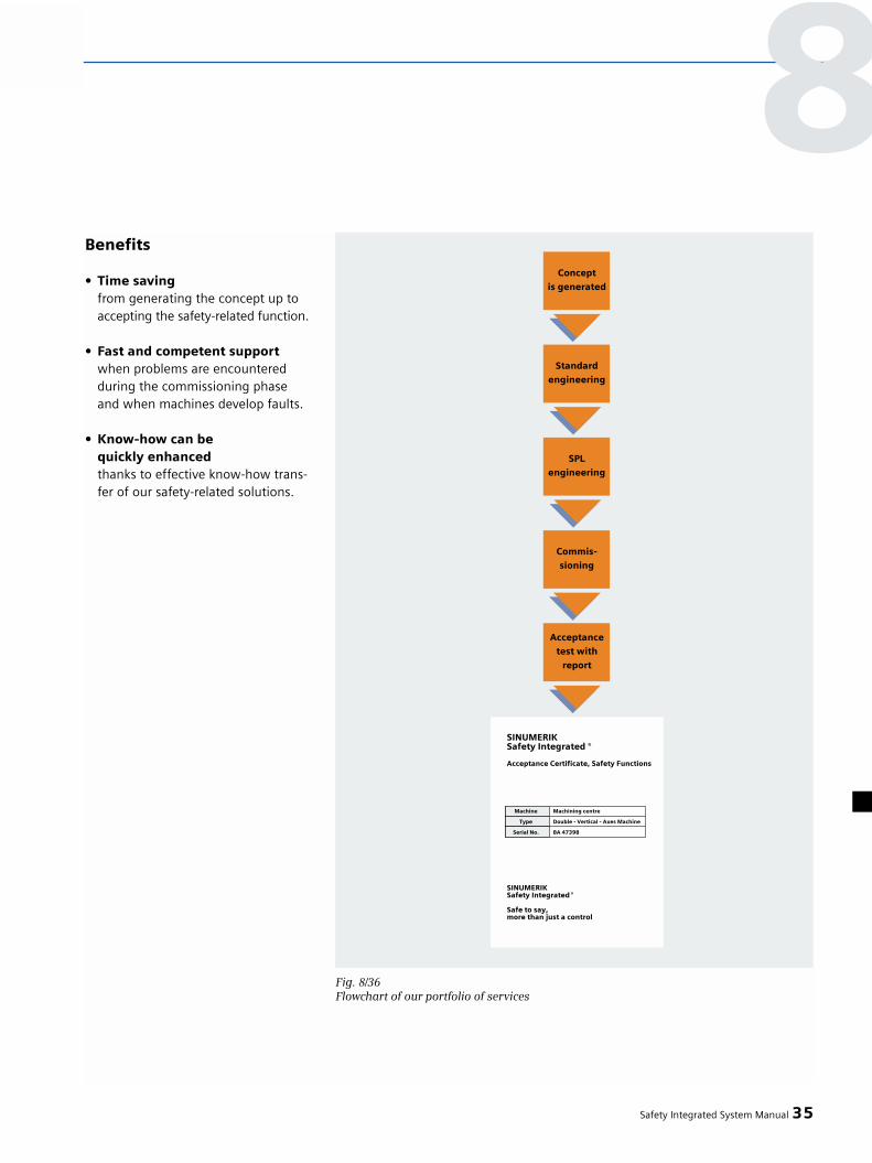
Benefits
• Time savingfrom generating the concept up toaccepting the safety-related function.
• Fast and competent supportwhen problems are encounteredduring the commissioning phaseand when machines develop faults.
• Know-how can bequickly enhanced thanks to effective know-how trans-fer of our safety-related solutions.
Safety Integrated System Manual 35
8
Fig. 8/36Flowchart of our portfolio of services

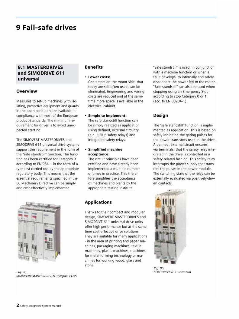
Overview
Measures to set-up machines with iso-lating, protective equipment and guardsin the open condition are available incompliance with most of the Europeanproduct Standards. The minimum re-quirement for drives is to avoid unex-pected starting.
The SIMOVERT MASTERDRIVES andSIMODRIVE 611 universal drive systemssupport this requirement in the form ofthe “safe standstill” function. The func-tion has been certified for Category 3according to EN 954-1 in the form of atype test carried-out by the appropriateregulatory body. This means that theessential requirements specified in theEC Machinery Directive can be simplyand cost-effectively implemented.
Benefits
• Lower costs:Contactors on the motor side, that today are still often used, can be eliminated. Engineering and wiring costs are reduced and at the same time more space is available in the electrical cabinet.
• Simple to implement:The safe standstill function can be simply realized as application using defined, external circuitry (e.g. SIRIUS safety relays) and integrated safety relays.
• Simplified machineacceptance:The circuit principles have beencertified and have already beenimplemented a multiple number of times in practice. This there-fore simplifies the acceptance of machines and plants by theappropriate testing institute.
Applications
Thanks to their compact and modulardesign, SIMOVERT MASTERDRIVES andSIMODRIVE 611 universal drive unitsoffer high performance but at the sametime cost-effective drive solutions.They are suitable for many applications- in the area of printing and paper ma-chines, packaging machines, textilemachines, plastic machines, machinesfor metal forming technology or ma-chines for working wood, glass andstone.
“Safe standstill” is used, in conjunctionwith a machine function or when afault develops, to internally and safelydisconnect the power fed to the motor.“Safe standstill” can also be used whenstopping using an Emergency Stopaccording to stop Category 0 or 1 (acc. to EN 60204-1).
Design
The “safe standstill” function is imple-mented as application. This is based onsafely inhibiting the gating pulses forthe power transistors used in the drive. A defined, external circuit ensures, via terminals, that the safety relay inte-grated in the drive is controlled in asafety-related fashion. This safety relayinterrupts the power supply that trans-fers the pulses in the power module.The switching state of the relay can beexternally evaluated via positively-driv-en contacts.
2 Safety Integrated System Manual
9 Fail-safe drives
9.1 MASTERDRIVES and SIMODRIVE 611 universal
Fig. 9/1SIMOVERT MASTERDRIVES Compact PLUS
Fig. 9/2SIMODRIVE 611 universal

Safe standstill function (SH)
Using the “safe standstill function”, the drive pulses are cancelled and thepower feed to the motor disconnected.The drive is in a safety-related no-torque condition. A feedback signalcontact is used to display its switchingstatus which means that it can bemonitored.
Technical data
Safety Integrated System Manual 3
Safety function • Safe standstillSafety classes that can be achieved Up to Category 3 acc. to EN 954-1Degree of protection IP20Control versions • Closed-loop servo control
• Closed-loop vector control (only MASTERDRIVES)
• V/f open-loop control (only MASTERDRIVES)
Additional features • Technology functions• Positioning• Free functional blocks
(only MASTERDRIVES)
SIMOVERT MASTERDRIVES / SIMODRIVE 611universal
9

Safety functions integratedin the drive itself
Overview
The SINAMICS S120 drive system sup-ports the requirement for “avoidingunexpected starting” using integratedsafety functions. In addition to the“safe standstill”, for the first time, “safebrake control” has also been integratedinto the drive. These functions havebeen certified according to Category 3(EN 954-1) and SIL 2 (IEC 61508) bythe appropriate regulatory body in theform of a prototype test. This meansthat the essential requirements speci-fied in the EC Machinery Directive canbe simply and cost-effectively imple-mented. During engineering, commissioning
and diagnostics, the “Starter” engi-neering software supports all of thesafety functions.
Benefits
• Lower costs:In many cases, external switchingdevices can be eliminated. Integratingthe safety technology allows safety concepts to be created in-line with those required in practice and at the same time the installation system is simplified. Not only this, but less spaceis required in the electrical cabinet.
• Higher degree of reliability:The functionality has been implemented completely electronically. This means that components with contactsthat were used earlier - e.g. integratedsafety relays and line contactors - can be eliminated.
• Simplified machine acceptance:Acceptance of machines and plants by the appropriate testing instituteis simplified thanks to certified,integrated safety-related functions.
Applications
As a result of its innovative featuresand characteristics, SINAMICS S120 ispredestined as a drive system in alltypes of production machines.For example, printing and paper ma-chines, packaging machines, textilemachines, plastic machines, machinesfor metal forming technology andmachines to work wood, glass andstone.
With these applications, the integratedsafety functions form the basis toimplement safety concepts for ma-chines and plants that are in line withthose required in practice.
4 Safety Integrated System Manual
9 – Fail-safe drives
9.2 SINAMICS Safety Integrated
Fig. 9/3SINAMICS S120
Fig. 9/4Configuring the safety function
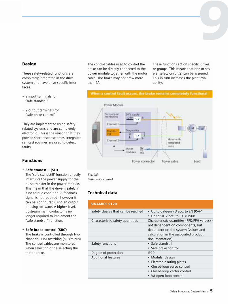
Design
These safety-related functions arecompletely integrated in the drive system and have drive-specific inter-faces:
• 2 input terminals for“safe standstill”
• 2 output terminals for “safe brake control”
They are implemented using safety-related systems and are completelyelectronic. This is the reason that theyprovide short response times. Integratedself-test routines are used to detectfaults.
Functions
• Safe standstill (SH)The “safe standstill” function directly interrupts the power supply for the pulse transfer in the power module. This mean that the drive is safely in a no-torque condition. A feedback signal is not required - however it can be configured using an output or using software. A higher-level,upstream main contactor is no longer required to implement the “safe standstill” function.
• Safe brake control (SBC)The brake is controlled through two channels - P/M switching (plus/minus).The control cables are monitoredwhen selecting or de-selecting the motor brake.
The control cables used to control thebrake can be directly connected to thepower module together with the motorcable. The brake may not draw morethan 2A.
These functions act on specific drivesor groups. This means that one or sev-eral safety circuit(s) can be assigned.This in turn increases the plant avail-ability.
Safety Integrated System Manual 5
Fig. 9/5
Safe brake control
Safety classes that can be reached • Up to Category 3 acc. to EN 954-1• Up to SIL 2 acc. to IEC 61508
Characteristic safety quantities Characteristic quantities (PFD/PFH values) - not dependent on components, but dependent on the system (values and calculation in the associated product documentation)
Safety functions • Safe standstill• Safe brake control
Degree of protection IP20Additional features • Modular design
• Electronic rating plates• Closed-loop servo control• Closed-loop vector control• V/f open-loop control
SINAMICS S120
Technical data
9

Overview
The frequency converter supplementsthe distributed SIMATIC ET 200S I/Osystem. The SIMATIC ET 200S has afinely modular design comprising com-ponents with distributed intelligence,
inputs and outputs, motor starters andsafety technology. The frequency con-verters - designated SIMATIC ET 200SFC - continuously control the speed ofinduction motors. They also solve driveapplications using simple open-loopfrequency control up to sophisticatedclosed-loop vector control.
ET 200S FC frequency converters areavailable in a standard version and in
a fail-safe version. In addition to the“safe standstill” the fail-safe frequencyconverter offers integrated safety func-tions - “safely reduced speed” and “safebraking ramp”. These can also be usedfor the first time in conjunction withsensorless standard induction motors.All of the safety-related functions havebeen certified according to Category 3in compliance with EN 954-1 and SIL 2in compliance with IEC 61508.
ET 200S FC frequency converters arecommissioned using “Starter” - a screen-based engineering tool. Starter” alsosupports the commissioning and diag-nostics of the integrated safety func-tions.
6 Safety Integrated System Manual
9 – Fail-safe drives
Fig. 9/6
ET200S station with inputs/outputs, motor starters and ET 200S FC frequency converters
9.3 SIMATIC ET 200S FCfrequency converters
Fig. 9/7
ET200S FC fail-safe frequency converters,
size B (2.2 kW or 4.0 kW)
Benefits
• Flexible solutionIn an ET 200S station fail-safe and standard components can be opera-ted together. This also applies to frequency converters. This means that flexible solutions that are easyto engineer can be implementedwith low hardware costs and for the widest range of drive applications.
• Lower costsIn many cases, external switching devices can be eliminated by using the “safe standstill” function. Theintegration of safety technology allows safety-relevant concepts to be created in line with those requi-red in practice - and at the same time the installation system is sim-plified. Not only this, less space is required in the electrical cabinet.
Up until now, it is also uniquein so much that the “safe brakingramp” and the “safely-reduced speed” functions neither require motor encoder nor encoder - and can be implemented with minimumcosts.
• Higher degree of reliabilityThe “safe standstill” is purely elec-tronic without any contacts and therefore ensures the shortest and most reliable response times.
• Simplified machine acceptanceThe acceptance of machines and plants by the appropriate testing bodies is simplified thanks to thecertified, integrated safety functions
Applications
• In addition to basic drive applications- for instance conveyor belts - the frequency converter also supportsapplications such as winder andunwinder drives and hoisting gear. When equipped with a motor enco-der, the applications extend up to precise closed-loop speed and cur-rent control.
• The ET 200S FC frequency converter can regenerate into the line supply. This significantly simplifies applica-tions with permanent regenerative operation. Examples include unwin-ders, lowering loads in crane appli-cations or electrically braking loads with higher moments of inertia.
• The “safe braking ramp” functionallows a drive to be safely stopped and monitored, even when sensor-less induction motors are being used. After the drive has been stopped, the drive is prevented from restartingby the “safe standstill” function.
• The “safely reduced speed” allows a drive to be slowly moved in hazardousareas. For instance, when setting-up or loading materials. This functioncan also be implemented without a motor encoder when standard induc-tion motors are used.
Comment:
The “safe braking ramp” and “safely re-duced speed” functions of the SIMATICET 200S FC frequency converter maynot be used for loads that drive themotor.
Safety Integrated System Manual 7
9

9 – Fail-safe drives
Design
The fail-safe ET 200S FC frequencyconverters comprise the followingcomponents:
• ICU24F control module
• IPM25 power unit (this is available in two sizes with power ratings from 0.75 kW, 2.2 kW and 4.0 kW)
• Terminal modules to connect the wiring and to accommodate the control unit and power unit
After the modules have been inserted,the control unit and power unit of thefrequency converter are connectedwith one another.
Functions
• Safe standstill (SH): “Safe standstill”interrupts the power supply for the pulse transfer in the power unit and also cancels the pulses. This means that the drive is safely in a no-torquecondition and is protected against restarting.
In addition, when shutting down via the individual shutdown paths,a process update is carried-out by
checking the expected status resul-ting from the particular switching action.
• Safe braking ramp (SBR): This monitors the drive while it is stopping.The drive is braked along a selectableramp. While stopping, a check is continuously made as to whether the actual speed tracks the specifiedramp function. “Safe standstill” isactivated after a minimum speedhas been fallen below (this can be parameterized).
If the braking function fails, “safe standstill” is immediately initiated and the drive goes into - the fault condition.
8 Safety Integrated System Manual
Fig. 9/8
ET 200S station with IM 151, fail-safe and standard inputs/outputs, fail-safe motor starters
and frequency converters

• Safely reduced speed (SG): Monitors the speed against an upperlimit value.
If, when initiating “safely reducedspeed”, the speed is greater than thesafety-related limit value, then the drive speed is initially reduced using the “safe braking ramp”. In this case, zero speed is not the target speed, but the safe speed limit value.
If, when initiating “safely-reduced speed”, the speed is less than the safety limit value, the monitoring for the reduced speed limit valueimmediately becomes active.
When the monitoring functionresponds, the drive is stoppedusing the “safe braking ramp”. The frequency converter thengoes into the fault condition.
Safety Integrated System Manual 9
Fig. 9/9
Safe braking ramp of the SIMATIC ET 200S FC frequency converter
Fig. 9/10
Safely reduced speed of the SIMATIC ET 200S FC frequency converter
9

Integration
The ET 200S FC frequency converter iscompletely integrated into the ET 200Ssystem and therefore has none of itsown inputs and outputs. The converterfail-safe functions are controlled, with-in the ET 200S, using signals in thebackplane bus - more precisely usingsafety shutdown groups of a PM-D Fpower module. The frequency conver-ter evaluates two of these shutdowngroups via safety-related inputs.
SIMATIC ET 200S provides three basicways of configuring fail-safe plants/sys-tems - and therefore to control the fail-safe frequency converter functions.
Safety-related signals are evaluated bya central fail-safe CPU and the fail-safefunctions of the ET 200S FC frequencyconverter are controlled via the PM-D FPROFIsafe power module.
The IM 151 High Feature interfacemodule is used to transfer PROFIsafedata communications along the ET 200Sbackplane bus.
10 Safety Integrated System Manual
9 – Fail-safe drives
• Controlling the safety functions via PROFIsafe

An interface module with integratedfail-safe CPU (IM 151-7 F-CPU) permitsfail-safe input modules to be evaluatedand the frequency converter to be con-trolled within the ET 200S station. Thismeans that the fastest response timesare guaranteed.
A fail-safe central CPU is not requiredin this configuration
A conventional, local solution to con-trol the safety functions can be imple-mented using a PM-D F X1 power mo-dule.
The shutdown groups are fed directlythrough the terminals of the PM-D FX1 power module - for example froman external 3TK28 device.
For this solution, any IM 151 interfacemodule can be used. A fail-safe CPU isneither required in the ET 200S norcentrally.
Safety Integrated System Manual 11
• Controlling the safety functions using a fail-safeIM 151-7 F-CPU
• Controlling the safety functions directly
9
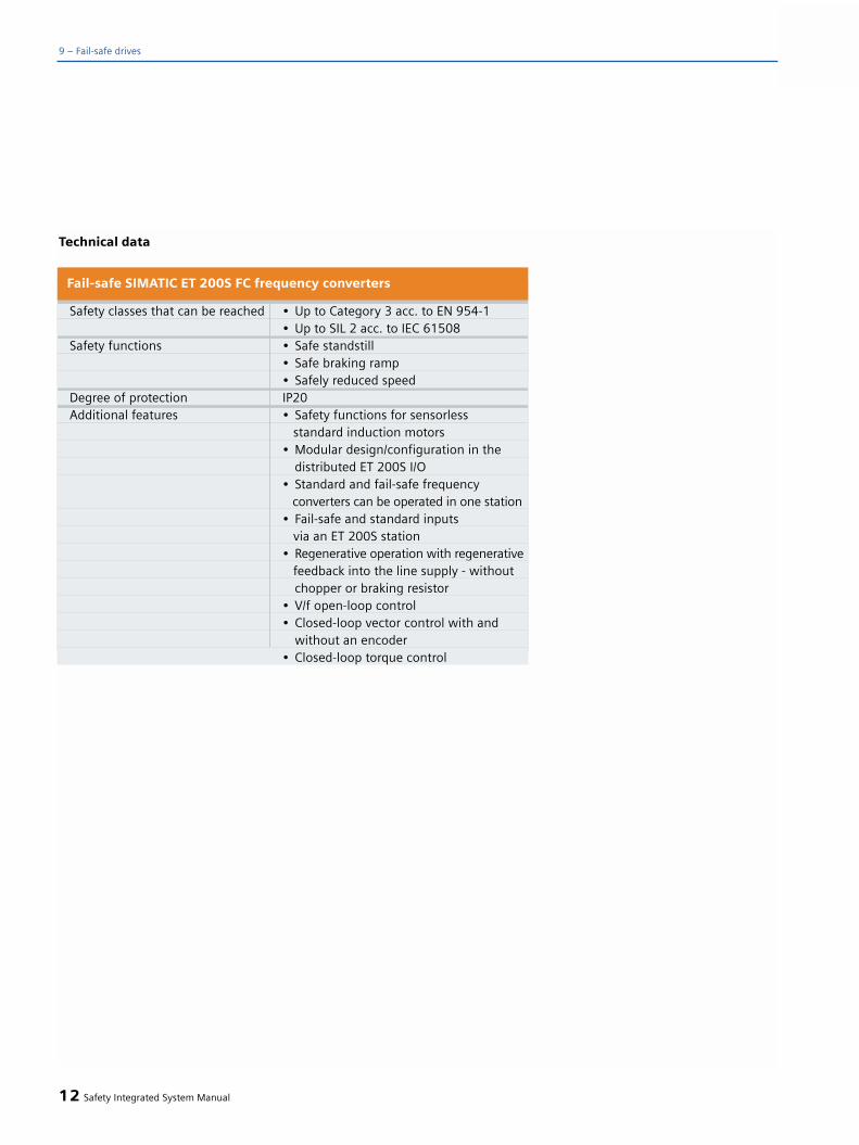
12 Safety Integrated System Manual
9 – Fail-safe drives
Safety classes that can be reached • Up to Category 3 acc. to EN 954-1• Up to SIL 2 acc. to IEC 61508
Safety functions • Safe standstill• Safe braking ramp• Safely reduced speed
Degree of protection IP20Additional features • Safety functions for sensorless
standard induction motors• Modular design/configuration in the
distributed ET 200S I/O• Standard and fail-safe frequency
converters can be operated in one station• Fail-safe and standard inputs
via an ET 200S station• Regenerative operation with regenerative
feedback into the line supply - without chopper or braking resistor
• V/f open-loop control• Closed-loop vector control with and
without an encoder• Closed-loop torque control
Fail-safe SIMATIC ET 200S FC frequency converters
Technical data

Safety Integrated System Manual 13
9

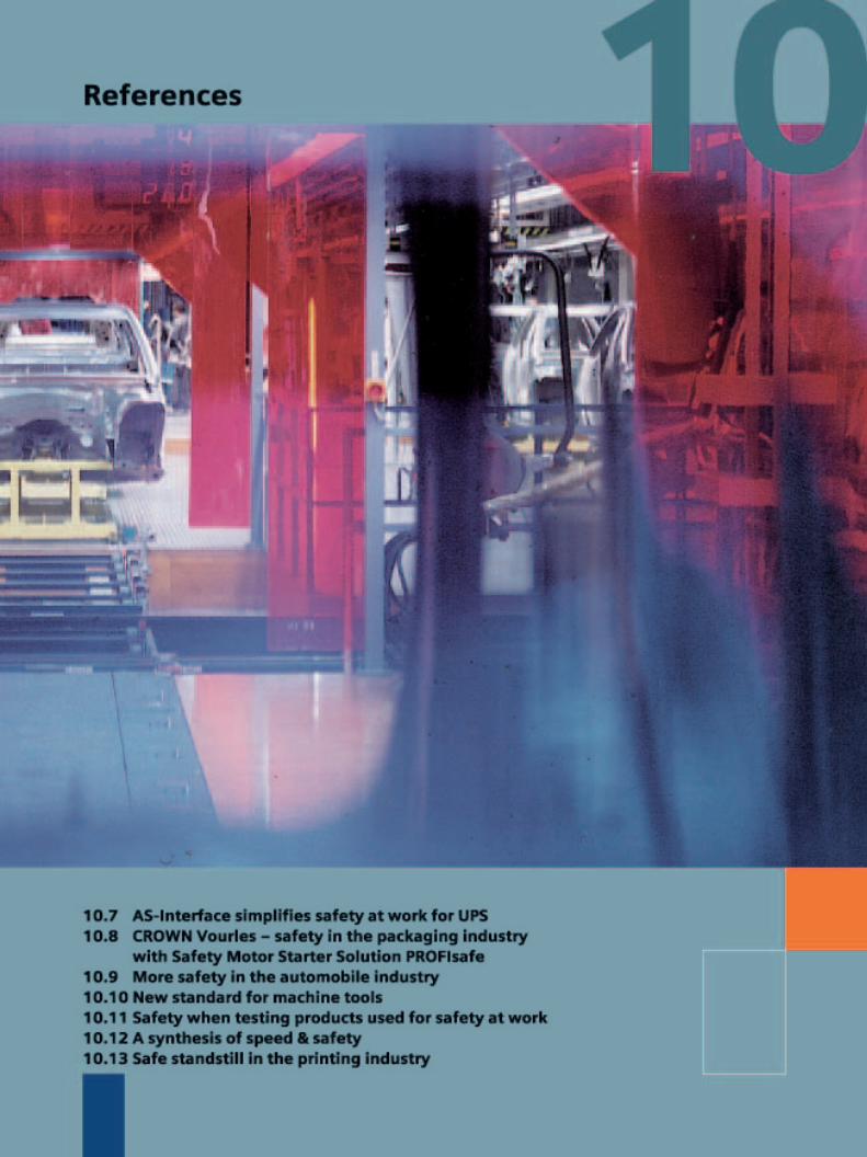

For Opel Antwerp/Belgium, recent-ly, the first automation and safetyproject was implemented based on Safety Integrated with fail-safeSimatic controllers. In addition tothe unique Safety Integrated tech-nology of Siemens, decisive for theproject success was also the closecooperation between the engi-neering team of Opel in Antwerp,the system integrator Imtech andSiemens Automation and Drives.
Opel Belgium n.v., an important Opelplant located in the Port of Antwerpand one of the crown jewels of Belgiumautomobile assembly is presently buil-ding various models of the Opel Astrafor more than 100 international plantsand facilities.
From safety relay to fail-safecontrol
Francis Luyckx, responsible for engi-neering at the Opel Belgium bodyshop, explained the situation beforethe retrofit: "In the body shop, all of the machine and transport movements(involving robots and conveyors) thatcould be potential sources of danger,are protected by safety cages, light cur-tains, safety switches and emergencystop devices. However, all of this, asbefore is controlled using relay circuits.
“We wanted to change all of this”, explained Francis Luyckx. "And itessentially comprises two projects, or more precisely, a double project: On one hand, the robots that werenewly installed, had to be equippedwith a control and a safety system -while on the other hand, the existingcontrol and safety system had to bereplaced. This was because the oldinstallation based on safety relays hadalready been frequently upgraded to
take into account different situations.In the meantime this system could nolonger conform to the latest safetystandards and the required additionalsafety functions."
2 Safety Integrated System Manual
10 References
10.1 Fail-safe SIMATICcontrollers in the bodyshop of Opel Belgium
The combination of new safety stan-dards and functionality, especially interms of detailed and reliable faultreporting, should be able to be easilyexpanded and favorable lifecycle costsachieved. Francis Luyckx added: “The decision between a system withseparate PLC for the control and safetyrelays for the safety system on the onehand, and a real fail-safe control onthe other hand, was quickly made: The latter is not only flexible, but italso reports faults down to the lastwire. And, when all is said and down,the complete system is even morecost-effective.”
The almost obvious choice...
“We specifically selected the Siemenssolution. The reasons were extremelyconvincing: Firstly, here at Opel we like to use Profibus. In addition to thepositive experience with this fieldbus,in the meantime, internally we haveestablished a lot of experience withProfibus. As we now have access to the new Safety Integrated technologythrough Siemens, then the decision toselect a fail-safe PLC with completelyintegrated safety functions was a clearcut case. And, the positive spin-off -we are open for future developmentsin the automation environment.”
Opel Belgium sees the advantage ofTotally Integrated Automation, last butnot least, due to the specific character-istics of this huge automobile plant.Endless preparation cells and typicalfeeder systems to the assembly line ofthe Opel Astra are increasingly deman-ding more and more smaller distrib-uted automation units. The practicaladvantages are obvious: Flexibility,shorter cables, extensive networkingcapabilities and integration on Profibus.
And – what is extremely important –we have the necessary time to runtests. “Everything that can happenoffline and therefore beforehand is toour benefit,” explained Francis Luyckx.
Further refining
We now want to further integrate thesafety functions in the requirementspecifications. Initially, this involvedthe fault reporting. Fault reports wereto be generated by making the appro-priate parameter assignments with thestandard Siemens software on the HMIpanels. Of course, it is also possible toimplement additional types and formsof safety-related intelligence - for exam-ple “muting functions” (programmedand safety-related suppression of safe-ty functions that can be required fornormal production operations) by usingsafety light curtains.
For Eric Moons, the E-mail card that is in fail-safe PLC plays a central role.“The central Opel safety/security servic-es in Antwerp now have, as requested,a new option to monitor the safety-related software. As soon as the safety-related software is modified, an E-mailis automatically sent to the securityservices.”
Together with the machinery construc-tion company Comau, the specialistsfrom Siemens Automation & Drivescommissioned and programmed thefirst fail-safe SIMATIC S7-315F. Imtechthe system integrator handled the sec-ond fail-safe S7-416F fail-safe control –independently and without any prob-lems. Wim Van Goethem, a projectengineer with Imtech briefly outlinedhis experience: “With help in the formof training from Siemens, we wereable to create a basis so that we were
able to very quickly program andimplement the system”.
The positive experience of the Opelteam after two months use says it all: “The system was installed andstarted-up and then we literally imme-diately forgot about it” explainedFrancis Luycks. “It operates completelysmoothly – not a single problem wasencountered. We must now get usedto the fact that we have a system inwhich the safety is really and com-pletely integrated. Previously, the safe-ty-related functions had to be sepa-rately programmed and therefore hadto be explicitly seen. Now, everythingis embedded in the system. Althoughwe know and understand this, fromtime to time, we still have the reflex to want to see things separately - as if we really want to see that Standard61204 is fulfilled.”
On the shop floor
Both fail-safe SIMATIC controllers areused in the metal finishing area - wherethe basic automobile bodies are fin-ished. One of the fail-safe controllershandles the function of the stud-weld-ing system as well as the transportsystem which transports the automo-bile body to where the trunk lid or tail-gate is mounted.
Safety Integrated System Manual 3
10

The second fail-safe controller is usedfor finishing - for example, polishing -visually checking the surface qualityand fitting. This includes fitting andopening the doors as well as openingthe trunk lid before the automobilebody is transported to the paintingshop. Both of the systems require com-plex transport movements without thewhole area. This is all supplemented by highly specialized manual work car-ried-out by technicians so that numer-ous potentially hazardous movementsmust be reliably screened-off andsecured.
“The physical security system compris-es trip lines, standard Emergency Stopswitches, light curtains with and with-out ”muting“ functions and classicsafety cages with safety-related locks -explained Francis Luyckx. ”This is anextremely complex arrangement wherethe fail-safe SIMATIC really comes intoits own. This is because it checkseverything and communicates withstandard control systems via ProfibusDP/DP couplers. However, during theyear, we want to take the next stepand make it essentially superfluous.Just one fail-safe SIMATIC controlshould handle both the safety-relatedcontrol as well as also the standardcontrol of the production process."
(from move-up 1-2/2003)
Toyota Canada chose a safety so-lution with Siemens AS-Interfaceat Work and SIMATIC S7-300F fortheir new Lexus factory and aplant retrofit. In addition to theenhanced safety, the automobilemanufacturer also profits from thehigher availability and thusincreased productivity.
Toyota Motor Manufacturing Cambridge(TMMC) in the south of the Canadianprovince of Ontario is a real referenceplant in the automobile industry. It isconsistently rated under the Top 10 byJD Power and Associates and was hon-ored by the parent company when itbecame the first Lexus plant outsideJapan in which the brand new LuxusOffroader RX 330 is to be built - a modelfrom the Lexus series.
For the new Lexus factory as well asthe existing Corolla plant, safety sys-
tems are now used which, in additionto a maximum degree of safety, alsooffer increased diagnostic capabilities- therefore allowing production to beboosted. Together with Siemens Canadaand consulting engineers Stantec,TMMC developed a leading-edge solu-tion with AS-Interface Safety at Workand a fail-safe SIMATIC S7-300F PLC.This will be cost-effectively used inboth the new Lexus plant as well aswhen retrofitting the Corolla plant.Siemens machine safety program
manager Ondrej Benjik, together withthe TMMC project manager Scott Bartlett,defined the retrofit strategy. He recalls:"For the retrofit it was important thatthe new safety solutions could be inte-grated into the existing control platform.Existing field devices and cabling wereto be replaced. The retrofit was to beexecuted with either none or a verylimited scheduled downtime. Further,Toyota placed considerable significanceon the effective use of the new systemsin operation such as quickly resolvingoperational faults.
4 Safety Integrated System Manual
10 – References
10.2 Safety technologyfor Toyota Canada

All safety regulations met
The Siemens Actuator-Sensor Interfaceproducts have proven themselves wellsuited to the challenge. The require-ments of the Canadian safety at workregulations that specifies safety testsbefore production starts for all safety-related devices and equipment wascomplied with in full.
“The retrofit went extremely smoothly”recalled Bartlett, “Toyota employeesreadily accepted the concept andimmediately understood the signifi-cance of the system.” Performed onweekends and during the holiday shut-down, the robot cells in the Corollapaint shop were retrofitted withoutany production downtime.
The “anti-chip” booth which applies aprotective coating to a vehicle's rockerpanels and the “blackout” booth whichapplies underbody protection, wereupgraded to the new safety-relatedsystem with minimum changes to theexisting PLC control system. The AS-Interface safety network from Siemensis based on a non-proprietary standardwhich means that it can be easily inte-grated into almost every PLC. Light cur-tains, laser scanners, safety interlocksand Emergency Stop switches can bedirectly connected through AS-Interfaceand a bus - whereby the safety require-ments of Category 4 are fulfilled.Thanks to the unique direct connectionsystem of the AS-Interface system itwas no longer necessary to have dis-tributed I/O stations for the safety com-ponents and/or the safety input mod-ules. This reduced the costs for hard-wiring to almost zero. Thanks to thesimple and straightforward installation,the commissioning costs and retrofittime are significantly reduced. Further,
complete function tests are able to becarried-out before commissioning.
SIMATIC S7-300F for Lexus
The new Lexus RX 330 plant usesSiemens safety-related solutions thatare in full compliance with EN 954-1and the IEC 61508 Standards. The AS-Interface is used in the new paintshop. The fail-safe SIMATIC S7-300FPLC on Profibus is used in the bodyshop.
“The Toyota installation clearly provedthat the best safety solutions not onlyensure a higher degree of safety atwork”, summarized Benjik from Siemens- but also that business goals such ashigh availability and fast troubleshoot-ing are also supported."
Toyota Motor Corporation
Toyota Motor Corporation is the world'sthird largest automaker, producing afull range of models - from mini vehi-cles to large trucks. Global sales of itsToyota and Lexus brands, combinedwith those of Daihatsu and Hino,totaled 5.94 million units in 2001. As of March 2002, besides its 12 ownplants in Japan, Toyota has 54 manu-facturing companies in 27 countries/locations that produce Lexus andToyota vehicles and components -employs 246,700 people worldwide(on a consolidated basis), and marketsvehicles in more than 160 countriesand regions. Automotive business,including sales finance, account formore than 90 percent of the compa-ny's total sales. Diversified operationsinclude telecommunications, prefabri-cated housing and leisure boats.
Toyota minivan production fail-safe
After a long and intensive pilot phase,for its body shop of the “Sienna” mini-van, Toyota decided to use the newfail-safe technology based on fail-safe SIMATIC S7 PLC controllers andPROFIsafe. Since a production line gets continuously modified due tomodel changes, the use of a safety PLC with distributed system allows afast, easy and cost-effective adapta-tion. Toyota rated the Siemens safetyPLC as the most efficient solution interms of functionality and reliability in an automated line among severalother safety PLC suppliers evaluated.Presently, projects are running in threeToyota plants worldwide: Tahara (Japan),Indiana (USA) and Cambridge (Canada).A total of 170 PLC controllers withapproximately 2000 safety I/O modulesare installed in the three factories.
(from move-up 3/2003)
Safety Integrated System Manual 5
10
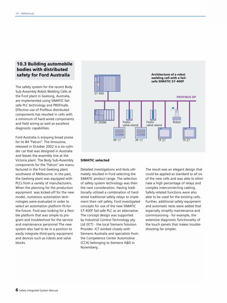
The safety system for the recent BodySub-Assembly Robot Welding Cells atthe Ford plant in Geelong, Australia,are implemented using SIMATIC fail-safe PLC technology and PROFIsafe.Effective use of Profibus distributedcomponents has resulted in cells witha minimum of hard-wired componentsand field wiring as well as excellentdiagnostic capabilities.
Ford Australia is enjoying broad praisefor its BA “Falcon”. The limousine,released in October 2002 is a six-cylin-der car that was designed in Australiaand leaves the assembly line at theVictoria plant. The Body Sub-Assemblycomponents for the “Falcon” are manu-factured in the Ford Geelong plantsouthwest of Melbourne. In the past,the Geelong plant was equipped withPLCs from a variety of manufacturers.When the planning for the productionequipment was kicked-off for the newmodel, numerous automation tech-nologies were evaluated in order toselect an automation platform fit-for-the-future. Ford was looking for a flexi-ble platform that was simple to pro-gram and troubleshoot for the serviceand maintenance personnel The newsystem also had to be in a position toeasily integrate third-party equipmentand devices such as robots and valveblocks.
SIMATIC selected
Detailed investigations and tests ulti-mately resulted in Ford selecting theSIMATIC product range. The selectionof safety system technology was thenthe next consideration. Having tradi-tionally utilized a combination of hard-wired traditional safety relays to imple-ment their cell safety, Ford investigatedconcepts for use of the new SIMATICS7-400F fail-safe PLC as an alternative.The concept design was supported by Industrial Control Technology ptyLtd (ICT) - the local Siemens SolutionProvider. ICT worked closely withSiemens Australia and specialists fromthe Competence Center Automotive(CCA) belonging to Siemens A&D inNuremberg .
The result was an elegant design thatcould be applied as standard to all sixof the new cells and was able to elimi-nate a high percentage of relays andcomplex interconnecting cabling.Safety-related functions were also able to be used for the existing cells.Further, additional safety equipmentand automatic tests were added thatespecially simplify maintenance andcommissioning - for example, theextensive diagnostic functionality ofthe touch panels that makes trouble-shooting far simpler.
6 Safety Integrated System Manual
10 – References
10.3 Building automobilebodies with distributedsafety for Ford Australia

These cells are mainly used for therobot welding equipment. Pressedbody parts are fed to the machiningstations where they are spot-welded.In some cases, the metal parts aretransferred by robots to other machines for further operations. Ford engineershave utilized the SIMATIC HMI systemsand distributed I/O with Profibus tomaximum advantage in the design of these cells. Robots are directlycontrolled through Profibus thereforepermitting fast disturbance-free datatransfer. Pneumatic components atthe clamping units are connected toProfibus through Festo valve blocks.
Operator stations are equipped withPP17 Operator Panels for operator inter-action and visualization. Further, the TP27 Touch Panel used allows productiondata and diagnostic information to beaccessed. On the larger cells, an MP 370Touch Panel additionally supplies thisdata and information at a central loca-tion.
The high resolution graphics of thesepanels allows photographic images ofclamping units to be displayed with thedynamic status of clamps and proximityswitches superimposed. This is an excel-lent way of clearly presenting diagnosticinformation to technicians and operators.
Central safety systems with SIMAT-IC S7-400F
The automation functions of the cellsare controlled by standard non-fail-safeladder code in the SIMATIC S7-400FPLC. This interacts closely with theprograms in the robots. Ford personnelprogrammed the robots according tothe process requirements and to inter-face to the supervisory PLC. In mostcases, ICT developed the standard PLCcode in close cooperation with Ford.Ford personnel configured and engi-neered subsequent cells themselves in-house. It goes without saying thatthe safety systems are a critical compo-nent of these cells. Light grids are gen-erally used for every cell. Light barriersprotect operator stations where partsare manually loaded. Using the two-hand control console, a part can beclamped while the technician remainswithin the area protected by the lightbarriers. Position switches at the robotbase monitor the orientation andtherefore allow manual access to amachine while the robot is presentlyworking at another. Light barriers alsoprotect access points for forklift truckswhen they fetch finished parts stackedon pallets.
Safety Integrated System Manual 7
10

10 – References
Safety interlocking functions in therobots, sensors in the fixtures, drivesfor the servo-driven rotary table and in a higher-level fast release valverespond to signals from light barriers,access gates and Emergency Stopdevices. All of these safety-relatedfunctions are implemented using a fail-safe SIMATIC S7-400F PLC. A safetyPLC also controls the electrical inter-locking at the access gate. The fact that these functions were implementedusing software resulted in a drasticreduction of electrical cabinet cablingand represents an implementation ofthe required safety logic in-line withthat required in the field.
New maintenance functions were ableto be added that would have beenimpossible with the previous, conven-tionally wired system. Diagnostic func-tions on the SIMATIC TP 27 TouchPanels supply detailed informationabout the status of the safety systemand the fault diagnostics. One of Ford'smain requirements was to block accessto programmed safety-related func-tions - but at the same time still allowfree access to standard code. This isimportant as modifications are re-quired from time-to-time and additio-nal systems are installed at the lineswhile the safety-related functions
typically remain constant. This require-ment was easily achieved using theSIMATIC S7-400F. Now, it is possible to modify the standard code withoutinfluencing the fail-safe code.
Distributed safety in LAD
The latest installation of distributed sa-fety-related technology is programmedin LAD and is based on “DistributedSafety”. This was well received by Fordpersonnel. The ability to program thefail-safe logic in LAD is considered tobe a simpler alternative to CFC thatwas used in earlier S7-400F systems.Ford wants to use LAD in all of itsfuture projects.
Ford has already announced that italso wishes to use the SIMATIC S7-315F for the safety I/O for smallermachines - that actually only require 1or 2 safety relays. This PLC is extremelycost-efficient and with a high degreeof performance. Just recently, engi-neering commenced work on 5 newcells. The distributed safety S7-315 PLCwill also be used for all of the automa-tion and safety-related functions forthese cells.
(from move up 1-2/2003)
8 Safety Integrated System Manual

Europe's leading manufacturer ofsteel truck wheels had to retrofitits proven rim profiling line tomeet the standard of the highestsafety Category 4 in compliancewith DIN EN 954-1. Initially, thistask appeared to be almost impos-sible as a result of the complexityof the system using conventionalsafety technology. However, thiswas able to be quickly handledusing fail-safe PLC and fieldbussystems and at the same time with a high degree of flexibility.
Solingen is not only the address forrazor sharp blades, but also the sourceof millions of wheels for automobilesand trucks all over the world. For themanufacturer, the wheel is what mostautomobile drivers would call a rim: Acombination of the so-called disk fixedto the hub and the rim that carries thetire. Both parts are made separatelyfrom coils of sheet steel that are thenformed, punched, joined, welded, test-
ed and painted in several stages. Michelin with a market share ofapproximately 50 percent is leader in its branch for steel truck wheels inEurope. The “wheels” business unit ofthis company that originally inventedthe tire, manufactures well over twomillion units per year. It goes withoutsaying that these wheels are crucialfor the safety of all drivers. They aremanufactured at Troyes (France),Aranda de Duero (Spain) and since1997 also in Solingen. In this steel city,the Michelin Kronprinz Werke GmbHmanufactures about 600,000 truckwheels per year on three dish lines and one rim line. This productioncapacity is to be doubled in the nextthree years when Solingen will advanceto become a development center andwill gradually absorb the manufactur-ing capacity of the Spanish daughtercompany.
Newly structured safety technology
For all its productivity, the mothercompany still places a great deal ofsignificance on safety at work. Thedeclared goal: Less than 5 accidents at work per factory and year. In orderto achieve this value over the longterm, Kronprinz carried-out a detailedrisk analysis of the rim profiling linethat had been producing rims for manyyears. Result: Safety Category 4 accord-ing to DIN EN 954-1 must be applied to the line comprised of 3 formingmachines. From a safety-related per-spective, this meant that the systemhad to be completely retrofitted.
Three protective areas were to beimplemented and a total of 24 protec-tive doors, 12 press safety modulesand 30 motors were to be integratedinto an integrated, seamless safetyconcept. The Europlan Systemtechnikfrom Kempen close to Krefeld - whohad already handled several similarjobs - were entrusted with the imple-mentation. However, up until now,they had always used conventionalsolutions, i.e. with hard wiring, safetycontrol and proprietary safety bus –not an easy task with almost 60 safetyrelays.
In the pre-planning phase, Siemenspresented its new fail-safe PLC con-trollers. “From the very start, I wasconvinced - especially as a result of the extensive fault diagnostic capabili-ty and the flexibility” recalled Dipl. Ing.Siegfried Schädlich, Head of ElectricalEngineering of the Wheels BusinessUnit. “This is the reason that we tookon the calculable risk and implementedour first PLC and fieldbus-based safetysolution.”
Safety Integrated System Manual 9
10.4 PLC-based safetyconcept in the manufac-ture of truck wheels forMichelin, Germany
10

Distributed system for total safety
A fail-safe SIMATIC S7-300F is the coreof the safety concept that was config-ured in parallel to the existing line con-trol. This was done for reasons relatingto time and costs. “Normal” and safety-related functions can be implementedtogether on one SIMATIC F-CPU; how-ever, with Kronprinz, the F-CPU (S7-315F) exclusively processes safety-related field signals. When faults occurthe F-CPU immediately switches theplant or the plant section into a safestate. Instead of a multiple number of single conductors, the safety equip-ment and devices are connected to
the CPU via a safety-related Profibusconnection. There are small local elec-trical enclosures close to the protectiveequipment and devices (protectivedoors, press safety modules). Theselocal enclosures have fail-safe SIMATICET 200S Profisafe signal modules thattransmit local signals to the centralcontrol station in the switchgear roomusing a conventional Profibus cable.The“Profisafe” protocol profile, devel-oped by the PNO guarantees error-freecommunications. This protocol fulfillsthe highest safety requirements withSIL 3 (IEC 61508) and Category 4 of EN 954-1.
Mechanical interlocks at the protectivedoors and additional interrogation rou-tines in the control program preventproduction from being unintentionallyinterrupted. Europlan implemented the link to the (SIMATIC) line controlrequired to coordinate the safetyequipment devices and equipmentwith the production process using abus coupling.
“One of the basic advantages of PLC-based solutions is naturally the highdegree of flexibility” - explainedSiegfried Schädlich - “this is becauseexperience has shown that it is verydifficult to precisely plan everything inadvance - and often additional require-ments are only received during thecommissioning phase. Using SIMATIC Fcontrollers, in the future, we will beable to quickly and flexibly respond to these late requirements.” With hard-wired safety relays, changes that areonly considered to be small, alwayscost us a lot of valuable time - andadditional requirements can often onlybe implemented with an over-propor-tional amount of time and costs. Onthe other hand, just the fact that theprotective equipment and devices areconnected through Profibus results in a high degree of flexibility when itcomes to expanding the functionality.“What also plays a role is to visualize allof the states and components on oneHMI device even when commissioningthe equipment. This saves a lot of time”- explained Mario Stärz a programmingengineer with Europlan. For conven-tional solutions, a lot of informationcan only be obtained in early projectphases by measuring individual signals- a time-consuming affair.
10 Safety Integrated System Manual
10 – References

Since the beginning of 2003, a SIMAT-IC TP270 Touch Panel in the local elec-trical cabinet continuously providesdetailed information about the currentstatus of the plant safety. The stan-dardized Profibus diagnostics modulefrom Siemens is integrated in the oper-ator interface. This allows faults to bequickly localized and resolved. Thismakes diagnostics extremely simple,helps to keep downtimes short andtherefore the degree of availability high.
Engineering as usual
PLC-based safety technology was anew area for Mario Stärz and he ex-clusively used the “Distributed Safety”software option package for Step7.This library includes block and applica-tion templates for safety-related taskscertified by the German TechnicalInspectorate [TÜV]. It is embedded inthe Step-7 environment so that evensophisticated safety-related tasks canbe quickly and reliably solved in thestandard languages F-LAD (ladderdiagram) and F-FBD (function chart).“This meant that different functions forthe setting-up and automatic modeswere just as simple to implement asflexibly grouping certain plant parts forsafe tool change or post machining(grinding) of tools in the line” explainedthe programmer. If, for some applica-tions, the functional scope is not ade-quate, the possibilities of the open sys-tem can be fully utilized. This meansthat blocks can be modified or engi-neers can generate their own blocksfrom the instruction set of the optionpackage.
Machine operators understand thebenefits of a high degree of trans-parency and the straightforward, user-friendly operation of the new safetytechnology utilizing touch panels. Upuntil now, the diagnostics capabilitywas not able to be proven in practiceas there wasn't one single fault in thesafety-related plant sections - such aswire breakage, short-circuit or cross-circuit fault.
Those responsible in Michelin Kronprinzfor the effective implementation ofsafety requirements - both technicallyand from a cost-effective perspective -think that the PLC-based solution withSIMATIC F controllers also offers signifi-cant benefits in far smaller plants andsystems: “Already with just two protec-tive circuits within a system, the increasein performance in the application cer-tainly makes the higher investmentcosts worthwhile” - explained SiegfriedSchädlich. He and Europlan are alreadyin the middle of detailed planning forseveral additional projects. Theseinclude, among others, a new complexwelding line for automobile wheelswith SIMATIC-controlled safety technol-ogy.
(excerpt from Blech Rohre Profile,Edition 8/03)
Safety Integrated System Manual 11
10

A safety system integrated in thestandard automation
Modern amusement rides andproduction equipment have some-thing in common: In both environ-ments, high-speed drives executeautomated motion. Not only this,downtimes are tabu - otherwisecost effectiveness goes out of thewindow. However, even whenevery attempt is made to maximizeturnover, safety of persons hastopmost priority.
A visit to Madame Tussauds in Londonincludes, in addition to the obligatoryexhibition of wax figures, also a trip onthe so-called “Spirit of London”. Visitorsare sent on a trip through time wherethey can experience London from itsearly beginnings up to the present day.Passengers travel through the historyof London in 87 London taxis. SiemensAutomation and Drives (A&D) upgrad-ed the safety and monitoring of thisexciting trip to bring it in-line with thelatest state of the art safety technologyso that passengers can be guaranteeda safe trip.
In Madame Tussauds, state-of-the-arttechnology ensures a high degree ofsafety.
Interdisciplinary technology
The “Spirit of London” is extremelysophisticated and involves numerousmechanical and electrical drives, syn-chronized lighting, sound and specialeffects as well as a multi-languageinformation system. A wide range oftechnologies - automated, driverlesssystems, industrial automation andtheater workshops - were combined inorder to create this unique indooramusement ride. The safety systemshave been designed so that safety canbe guaranteed no matter what faultoccurs – whether triggered by the sys-tem itself, the visitors or other events.
The company operating MadameTussauds contracted the local D.B.Brooks consulting company - that spe-cializes in amusement rides - to draw-up a detailed design for the requiredsafety technology. A joint evaluation ofthe alternatives quickly indicated thatthe use of Siemens AS-Interface Safetyat Work (safety technology integratedin the AS-Interface system) permittedthe highest possible degree of safetyand reliability but at the same timeretaining operational flexibility. Theintroduction of the new InternationalStandards EN 954-1 and IEC make thisall possible. These standards now per-mit that all of the safety-related andstandard operating control systems canbe completely integrated into oneanother.
12 Safety Integrated System Manual
10 – References
10.5 Exciting trip throughMadame Tussauds

Certified safety
These technical prerequisites are ful-filled when using AS-Interface Safety at Work and also implemented in thefield. As far as possible, safety-relatedfunctions are based on componentsthat have proven themselves in stan-dard operating automation over manyyears. In the case of AS-Interface, inaddition to signals from the standardoperating automation, safety-relatedsignals are also transferred in parallelon communication links that have notchanged from the hardware perspec-tive. Safety-related components thathave been specifically developed andcertified for transmitting, receiving andevaluating safety-related signals arecompatible with the existing communi-cations concept. This has resulted in a decisive lead when it comes to cost-effectiveness by being able to reducethe amount of wiring and providingsimpler diagnostics. The MadameTussauds application is especiallyimportant as it is the first applicationof AS-Interface Safety at Work in Eng-land in the area of highly developedamusement rides.
A SIMATIC S7-300 controller, core ofthe new installation, can access all of the actuators and sensors via AS-Interface. It is also linked to six opera-tor control devices that monitor everyaspect of the amusement ride. Thesafety-related signals are continuallyevaluated in parallel using an inde-pendent safety monitor.
The Siemens OP7 operator devices pro-vide access to all of the monitoring ele-ments at each location – from standardoperator control and maintenance stepsthrough safety-related elements up tofire alarm and evacuation systems.Extensive diagnostic data is embeddedin all of these systems.
SIGUARD light curtains - a Safety-Inte-grated product for applications up toEN 954-1 Category 4 - provide an opti-cal protective field. This field reliablydetects anybody that tries to leave theride. If an emergency situation doesarise, then it takes less than 2 secondsto stop the ride and to switch-on thelighting. The emergency evacuation issimul-taneously started together withthe safety lighting system and announce-ments.
Integrated system increases thedegree of safety
AS-Interface Safety at Work is a part ofSafety Integrated - a Siemens conceptthat combines all aspects of sequentialcontrol and data management in orderto provide the highest possible safetystandards for man, machine and theenvironment. It is a safety system fullyintegrated in standard operating auto-mation - Totally Integrated Automation.Users can enjoy many benefits regard-ing cost-effectiveness, flexibility andsafety thanks to this innovative safetytechnology solution.
Safety Integrated System Manual 13
10
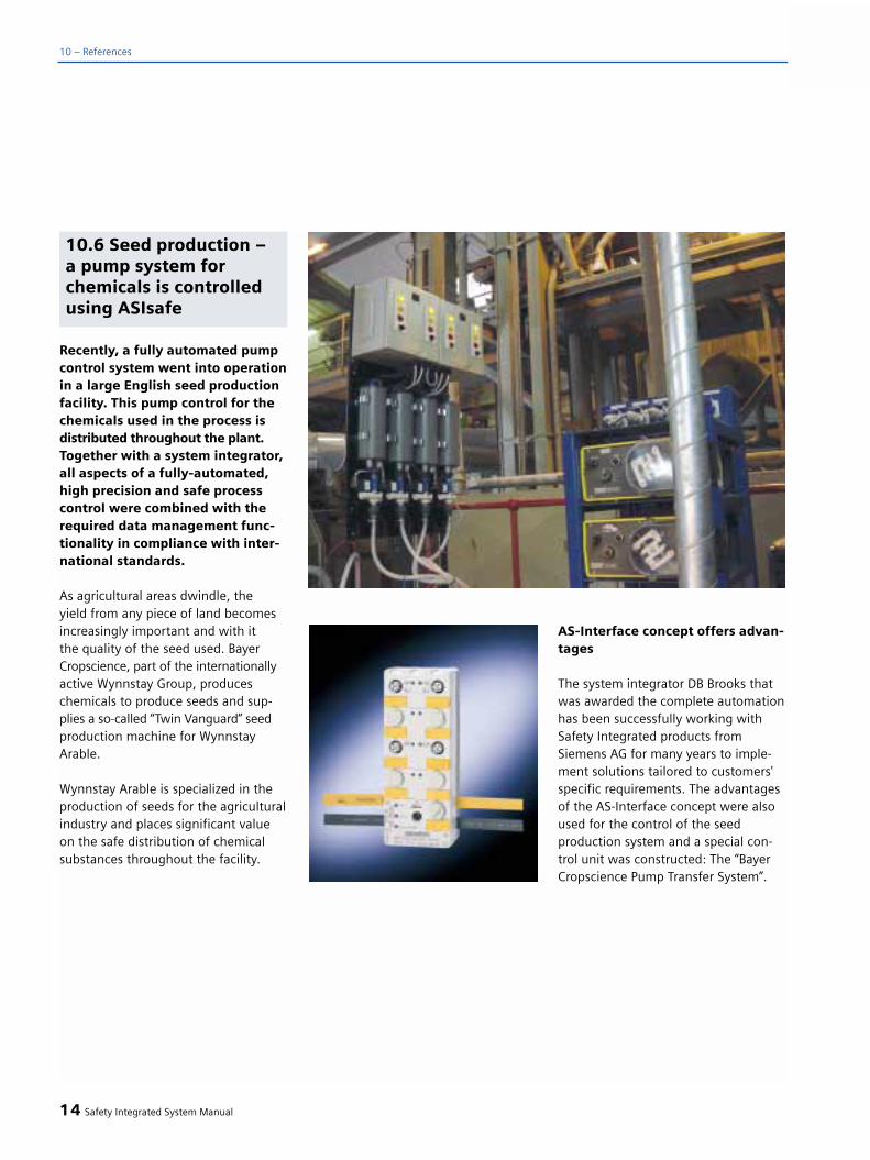
Recently, a fully automated pumpcontrol system went into operationin a large English seed productionfacility. This pump control for thechemicals used in the process isdistributed throughout the plant.Together with a system integrator,all aspects of a fully-automated,high precision and safe processcontrol were combined with therequired data management func-tionality in compliance with inter-national standards.
As agricultural areas dwindle, the yield from any piece of land becomesincreasingly important and with it the quality of the seed used. BayerCropscience, part of the internationallyactive Wynnstay Group, produceschemicals to produce seeds and sup-plies a so-called “Twin Vanguard” seedproduction machine for WynnstayArable.
Wynnstay Arable is specialized in theproduction of seeds for the agriculturalindustry and places significant valueon the safe distribution of chemicalsubstances throughout the facility.
AS-Interface concept offers advan-tages
The system integrator DB Brooks thatwas awarded the complete automationhas been successfully working withSafety Integrated products fromSiemens AG for many years to imple-ment solutions tailored to customers'specific requirements. The advantagesof the AS-Interface concept were alsoused for the control of the seedproduction system and a special con-trol unit was constructed: The “BayerCropscience Pump Transfer System”.
14 Safety Integrated System Manual
10 – References
10.6 Seed production –a pump system forchemicals is controlledusing ASIsafe
In order that the“Twin Vanguard” ma-chine manufactures the seed corre-sponding to the precise quality specifi-cations, the chemicals must be pumpedfrom the large containers at theground level up to where the machinesare located in the upper level. 36 litersof fluid must be precisely distributed toprocess 24 tons of seed per hour inbatch operation at intervals of 15 sec-onds. The automation technologymust have a high degree of safetyespecially in rugged industrial environ-ments. The risk of permanent damageto the complete plant, e.g. if the pumpsystem was to malfunction, is too highif a special safety system is not used.The effects of such a malfunctioncould have catastrophic effects on theenvironment.
Information is required to control theliquid flow. This information safelylinks all of the containers and preciselycontrols when and how much liquidshould be pumped from the individuallarge containers to the processingmachine.
All of the containers are connectedthrough a single AS-Interface cablewith its know “modular capability” -contrary to multiple cabling in a starconfiguration. This yellow, two-con-ductor cable also allows container lev-els to be graphically displayed on oper-ator panels also connected to the cable.
This information is then sent to aSIMATIC S7-200 PLC that sends itscontrol signals to the pump controls to either pump the liquid to themachines or fill the containers.
Simple, effective and highlyreliable
Jim Donald, Head of Production forBayer Cropscience explained: “In alarge production facility it can be diffi-cult to distribute chemicals preciselydosed. This is the reason that we arevery serious when it comes to safety -which is reflected in the fact that wedemand the highest possible stan-dards. During the planning phase, weclearly recognized that the SiemensAS-Interface would provide us withmany benefits. Apart from the fact thatthis is a simple, effective and highlyreliable solution, the danger of makingmistakes when installing the system is extremely low as only a single cableis used. Cost-saving was an additionalreason to use this system - not onlywere the wiring and installation costsreduced, but also the risk of mistakeswhen installing the system for the firsttime and when making subsequentmodifications.”
Hardly any production downtime
All of this became reality: The produc-tion interruptions at the Wynnstayfacility while installing the new auto-mation system were minimal. Thedevelopment engineers of the DBBrooks system integrator tested the AS-Interface without any significantadditional expense because they wereable to set it up in their own facilitybefore it was actually installed on-site.The simple network configuration andinstallation drastically reduced produc-tion downtimes in comparison to con-ventional cabling techniques.
(excerpt from VERFAHRENSTECHNIK 38 (2004) No.1-2)
Safety Integrated System Manual 15
10

120 employees at the UPS Centerin Aachen sort and handle up to20,000 parcels every day.
For the staff's safety, EmergencyStop command devices are locatedat the unloading stations andmany other points along the 700meter sorting plant. ASIsafe is thename of the control technologythat was installed and which isnow ensuring safety at the work-place.
The parcel sorting plant in Eschweiler/Weissweiler, Germany comes to lifewhen the clock in the UPS center inAachen strikes 4:30 a.m.
By 8:00 a.m. the parcels are sorted onan apparently endless belt whereworkers load all of the parcels as quick-ly as possible for the 50 deliverers withtheir characteristic brown trucks.Trouble-free, smooth sorting is crucial.But because UPS's company philosophynot only focuses on speed and preci-sion but also on the safety of its per-sonnel, those responsible in Eschweilerrely on safety switching elements fromthe Siemens ASIsafe program to addi-tionally increase safety. Instead of theprevious, conventional industrial con-trols that were used, UPS decided toinstall Emergency Stop commanddevices with AS-Interface. AS-Interfacealways provides advantages when sim-ple I/O devices are to be addressed bythe machine control.
Up to 62 slaves can be operated onone network with the new AS-InterfaceVersion 2.1. This type of configurationis of particular interest to logistic expertsbecause the necessary safety circuitshave recently been implemented withsafety monitors as are specified in sort-ing centers. Emergency Stop commanddevices are located wherever person-nel come close to moving parts andequipment. There are 26 EmergencyStop command devices in Eschweiler.
The UPS specialists quickly realized theadvantages of the AS-i safety technologyand therefore rejected a solution invol-ving a special safety bus system plusadditional costs for components,installation and maintenance. The3RK1105 safety monitors are directlyconnected to the SIMATIC S7-300 con-troller used in Eschweiler for the UPSsolution. It took about two weeks toretrofit the plant and this was carried-out in parallel to the old system without
16 Safety Integrated System Manual
10 – References
10.7 AS-Interface simpli-fies safety at work forUPS
50 delivery personnel start their tour with their typical brown trucks from the
UPS headquarters in Eschweiler close to Aachen.
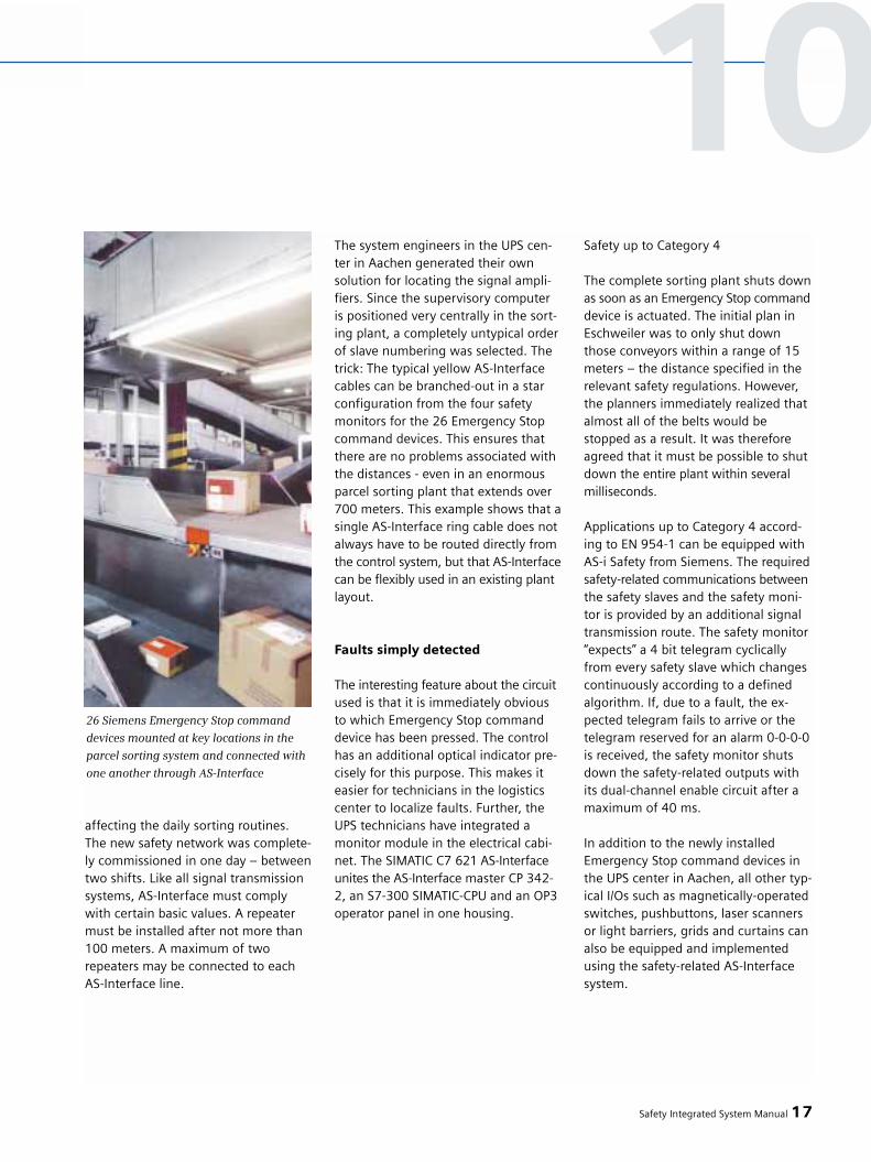
affecting the daily sorting routines.The new safety network was complete-ly commissioned in one day – betweentwo shifts. Like all signal transmissionsystems, AS-Interface must complywith certain basic values. A repeatermust be installed after not more than100 meters. A maximum of tworepeaters may be connected to eachAS-Interface line.
The system engineers in the UPS cen-ter in Aachen generated their ownsolution for locating the signal ampli-fiers. Since the supervisory computer is positioned very centrally in the sort-ing plant, a completely untypical orderof slave numbering was selected. Thetrick: The typical yellow AS-Interfacecables can be branched-out in a starconfiguration from the four safetymonitors for the 26 Emergency Stopcommand devices. This ensures thatthere are no problems associated withthe distances - even in an enormousparcel sorting plant that extends over700 meters. This example shows that asingle AS-Interface ring cable does notalways have to be routed directly fromthe control system, but that AS-Interfacecan be flexibly used in an existing plantlayout.
Faults simply detected
The interesting feature about the circuitused is that it is immediately obvious to which Emergency Stop commanddevice has been pressed. The controlhas an additional optical indicator pre-cisely for this purpose. This makes iteasier for technicians in the logisticscenter to localize faults. Further, theUPS technicians have integrated amonitor module in the electrical cabi-net. The SIMATIC C7 621 AS-Interfaceunites the AS-Interface master CP 342-2, an S7-300 SIMATIC-CPU and an OP3operator panel in one housing.
Safety up to Category 4
The complete sorting plant shuts downas soon as an Emergency Stop commanddevice is actuated. The initial plan inEschweiler was to only shut downthose conveyors within a range of 15meters – the distance specified in therelevant safety regulations. However,the planners immediately realized thatalmost all of the belts would bestopped as a result. It was thereforeagreed that it must be possible to shutdown the entire plant within severalmilliseconds.
Applications up to Category 4 accord-ing to EN 954-1 can be equipped withAS-i Safety from Siemens. The requiredsafety-related communications betweenthe safety slaves and the safety moni-tor is provided by an additional signaltransmission route. The safety monitor“expects” a 4 bit telegram cyclicallyfrom every safety slave which changescontinuously according to a definedalgorithm. If, due to a fault, the ex-pected telegram fails to arrive or thetelegram reserved for an alarm 0-0-0-0is received, the safety monitor shutsdown the safety-related outputs withits dual-channel enable circuit after amaximum of 40 ms.
In addition to the newly installedEmergency Stop command devices inthe UPS center in Aachen, all other typ-ical I/Os such as magnetically-operatedswitches, pushbuttons, laser scannersor light barriers, grids and curtains canalso be equipped and implementedusing the safety-related AS-Interfacesystem.
Safety Integrated System Manual 17
26 Siemens Emergency Stop command
devices mounted at key locations in the
parcel sorting system and connected with
one another through AS-Interface
10

Siemens offers their full range of safe-ty devices from the “Safety Integrated”portfolio. These devices are assigned to the safety monitors using simple-to-use AS-Interface configuration soft-ware.
Can be flexibly expanded
With the objective of gradually moderni-zing plant, the in-house technicianshave clearly noted “AS-i safety” in theirrequirement specifications for theirnext conversions.
The reason for this is that they all statesystem flexibility is incredibly impor-tant. Especially since not only single
signals but complete data packets cannow be transmitted. This closes animportant diagnostics gap in AS-Inter-face.
Logistic centers profit from the AS-Interface technology in two ways. Thisis because all of the industrial controlscan be quickly connected and discon-nected as a result of the insulation dis-placement system used to establishconnections. The technician no longerrequires a screwdriver to connect-upthe cables. Before an AS-Interfacedevice is removed, the technician sim-ply puts it into the service mode bypressing a button. The new device isthen simply inserted without having to be programmed. This is because
the individual “slot numbers” in an AS-Interface line-up are saved in the sys-tem itself. The technician then logs-onthe new device with the host by press-ing the button again. No specificallytrained personnel is required to dothis. This is particularly importantbecause logistic centers are usuallyexpansive and distances are long.
The technology is otherwise also veryuser-friendly. The experience of thoseresponsible at UPS is that faults can bequickly eliminated and commissioningis extremely fast. Every employee soonbecame familiar with the AS-Interfacedevices. This saves valuable time – amajor issue when it comes to logisticalsolutions.
18 Safety Integrated System Manual
10 – References
Stefan Höfer (right) Manager of the UPS Center Aachen and Heinz Czichy, Siemens consul-
tant are very happy about the new and simple safety solution using AS-i Safety. As a
result of the centrally located electrical cabinet, special AS-Interface cabling was able to
be implemented

After production line 22 belongingto “Crown Speciality PackagingFrance” – as the name suggests, a packaging company – was adapt-ed and modified in-line with theappropriate standards, it is nowrunning with PROFIsafe. The 416Fcentral processor of the S7-400simultaneously manages the stan-dard and safety-related inputs andoutputs. The control functions aresupported using touch screens thatare connected to the MPI bus. Thetechnology used allows testingand processing times to be halvedwhen using Safety MotorstarterSolution PROFIsafe.
CROWN Holdings in Vourles/Lyon inFrance is one of the market leaders inthe packaging industry. The companymanufactures special metal packaging.This includes cans for beverages andother products and special packagingfor large brand names (e.g. Bonduelle,Coca-Cola and others) in “small quanti-ties” - this means a maximum of mil-lion cans per production line and year.
“Especially so-called 3-section cans” areproduced - explained Gilles Guerrin,responsible for engineering at the facil-ity: “Each can comprises a rounded orwelded body, a drawn cover where theopening is located and also a drawnbase element.”
Industrial buckets with a diameter of220 mm and a capacity of either 5 or 6liters are produced on line 22. “Thehourly production rate exceeds 2500buckets - this therefore meant that theline had to be adapted to be compliantwith Dekret 9340 - the French Standardfor safety of machinery. The goal wasalso to increase the productivity by cor-rectly adjusting the line and in turnrequiring fewer personnel to operatethe line.”
Not only this, the automated produc-tion of the “funnel bucket” also includ-ed installing a new machine to locatethe rings therefore replacing two man-ual machines that up until then re-quired four operators.
Fourteen machines in series
Line 22 comprises 14 machines in seriesthat are supplied with steel sheets:
• The welding machine rolls the flatmetal sheet before the cylinderthat is formed is welded together.
• The hydraulic expander tapers the tubes.
• The forming machine forms the upper part of this taper so that it can accept the upper sections.
• The ring machine completes thisoperation. At the same time, a ring is inserted in the main body in order to avoid deep nesting of the buckets.This allows them to be easily separa-ted later on.
• Every bucket is turned-over before it runs-through the following machines:The bordering machine, then thecapping machine. The diameter is reduced while the edge is bent so that the base can be welded to the main body.
• The bucket is turned-over again before the seamer prepares theupper section of the bucket.
• The welding machine locates disks at both sides of the main body for handles. The handles are distributed using gravity using a centrifugal drum and positioned precisely atthe weld seam.
• The painting machine ensures thatthe welded elements are protected.
• The tunnel is used to dry the paintthat has been applied.
• The double ring capping machineswas renewed in the Lycée Lamache.
• The bar installation device attachesthe handle to the disks.
• The buckets are then automatically stacked.
Safety Integrated System Manual 19
10.8 CROWN Vourles –safety in the packagingindustry with SafetyMotor Starter SolutionPROFIsafe
10

The bucket production line wasadapted in compliance with theStandard
This meant that fourteen machineshad to be adapted. Extremely shortintervention times were required inorder to keep downtimes to a mini-mum and in turn minimize supplydelays to customers.
Preliminary work was started in May2003. The first machine was adaptedin compliance with the appropriateStandard the following September. Allof the line components were incorpo-rated after three additional modifica-tions.
This modification work affected thesafety in the following ways:
1. Machine protection: Non-controlledgrids were replaced by light curtainsand fixed protective grids were installedat the rear.
2. The conventional control panelswere replaced by SIMATIC Touch Panelswith two Emergency Stop commanddevices: One of these is an EmergencyStop device to locally stop the machineand the other to stop the complete line.
3. In order to implement the pneumat-ic distribution in compliance with theStandard, the distributors and thevalve supply blocks had first to bechanged as well as the control of thepneumatic supply.
Further, the following modificationswere made:
1. Sensors were installed at the hous-ings with the mechanical cam con-trollers that are extremely difficult toadjust; the settings of the sensors canbe modified directly at the OP with afar higher accuracy (to an accuracy of1 degree).
2. Finally, the electrical cabinets wererenewed, the connected safety relayswere replaced by an automated SIMAT-IC safety system: A central cabinet withS7-416F control is connected to otherelectrical cabinets using the ET 200S I/O.
“With Siemens and our installationcompany, we started to investigate the automation architecture required”,recalled Gilles Guerrin. “We have beenworking for 25 years with SNEF (acompany specializing in automatingindustrial operations) both in France as well internationally”. Gilles Guerrin:“Siemens was the only manufacturer of automation technology that imple-mented a safety PLC with standardfieldbus communications.”
Today, the line has three networks thatconnect the various machines:
1. A power network runs through thecomplete line. The central cabinet isconnected to every distribution cabinetclose to the machine.
2. 10 TP170B panels are connected to the MPI network (196 kbaud). They replace all of the conventionalknobs with the exception of theEmergency Stop command devices.
3. The PROFIBUS DP network withPROFIsafe profile connects the produc-tion systems with the SIMATIC S7-416Fcontrol. Safety-related telegrams areexchanged between standard devicesvia this network. The PLC is connectedto 19 DP slaves and more preciselywith 13 ET 200S I/O stations, 5 fre-quency inverters and 2 pneumaticblocks.
Further, there are a total of 248 inputsand 124 outputs, 64 safety inputs, 64safety outputs, 43 safety fail-safe motorstarters and 7 SSI modules to connectthe position sensors.
20 Safety Integrated System Manual
10 – References
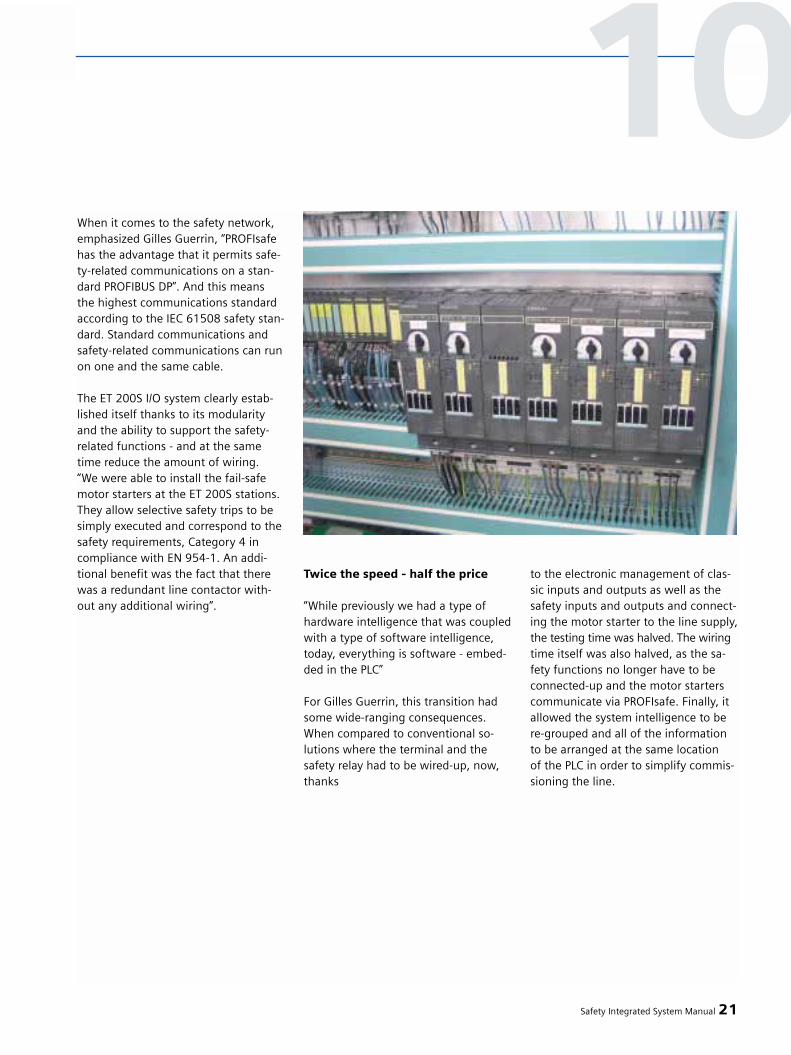
When it comes to the safety network,emphasized Gilles Guerrin, “PROFIsafehas the advantage that it permits safe-ty-related communications on a stan-dard PROFIBUS DP”. And this meansthe highest communications standardaccording to the IEC 61508 safety stan-dard. Standard communications andsafety-related communications can runon one and the same cable.
The ET 200S I/O system clearly estab-lished itself thanks to its modularityand the ability to support the safety-related functions - and at the sametime reduce the amount of wiring. “We were able to install the fail-safemotor starters at the ET 200S stations.They allow selective safety trips to besimply executed and correspond to thesafety requirements, Category 4 incompliance with EN 954-1. An addi-tional benefit was the fact that therewas a redundant line contactor with-out any additional wiring”.
Twice the speed - half the price
“While previously we had a type ofhardware intelligence that was coupledwith a type of software intelligence,today, everything is software - embed-ded in the PLC”
For Gilles Guerrin, this transition hadsome wide-ranging consequences.When compared to conventional so-lutions where the terminal and thesafety relay had to be wired-up, now,thanks
to the electronic management of clas-sic inputs and outputs as well as thesafety inputs and outputs and connect-ing the motor starter to the line supply,the testing time was halved. The wiringtime itself was also halved, as the sa-fety functions no longer have to beconnected-up and the motor starterscommunicate via PROFIsafe. Finally, itallowed the system intelligence to bere-grouped and all of the informationto be arranged at the same location of the PLC in order to simplify commis-sioning the line.
Safety Integrated System Manual 21
10

The new flexible production line in the Renault plant in Cleon in the North of France has been oper-ational since the end of 1998.Working around the clock, 40 ma-chines in the plant produce 5000cylinder heads every week. Each of the machines is equipped with a SINUMERIK 840D with SafetyIntegrated. We asked the head ofthe production line, Patrick Renault,about his experience with inte-grated safety technology fromSiemens.
Mr. Renault, the new production linehas been operational since September1998. What does the line consist of and whatis it producing?
Patrick Renault: In addition to a totalof 40 machines, there are also 13 load-ing gantries, entry and exit areas aswell as assembly units, measuring sta-tions and the labeling units. The lineoperates around the clock – the onlyexception is six hours on Sunday morn-ing. This line produces various cylinderheads for our 1.4 to 2.2 liter engines.
All of the 40 machines are equippedwith Safety Integrated in conjunctionwith a SINUMERIK 840D. What madeyou decide to use Safety Integrated?
Patrick Renault: It was the machineOEM (Grob) who first recommendedand implemented Safety Integrated. Inthe meantime we are extremely happyabout this decision. This is because the
machines operate with an extremelyhigh speed – 60 to 70 meters perminute at the machining centers and120 meters per minute at the loadinggantries – which means that it isabsolutely mandatory to provide amaximum of safety – and we canachieve this with Safety Integrated.
What additional advantages does in-tegrated safety have in comparison to conventional safety technology?
Patrick Renault: To start-off with, ithas a significantly shorter response timeas it is integrated in the SINUMERIK840D numerical control.
Further, safely reduced speed is possi-ble using Safety Integrated. This meansthat we can intervene with the protec-tive doors open and the machine stillrunning – and with 100% safety. Notonly this, but the drives no longer haveto be disconnected from the powersource. In turn, this extends the drivelifetime – as you know, the lifetime isreduced by frequently powering-upand powering-down the DC link.
Which criteria initiated you to useintegrated safety as standard on all of your production lines?
Patrick Renault: Renault's goals are quite clear: We only want to usemachines that fulfill Category 3 of the EN 954-1 safety Standard and wewant to achieve a high degree of safe-ty using fast response times. SafetyIntegrated fulfills these requirements.
Are the operating personnel satisfiedwith integrated safety?
Patrick Renault: The possibility ofmanually intervening in the machinewith the door open for service or whensetting-up the gantries creates a lot ofconfidence. Furthermore, the use ofSafety Integrated is quite transparent;this means that there are no problemsduring production. Operating person-nel have clearly understood that SafetyIntegrated offers them more safety andsecurity although the speed of theseproduction lines is significantly higher.
Mr. Renault, thank you for the interview.
22 Safety Integrated System Manual
10 – References
10.9 More safety in theautomobile industry
GROB machining center in the productionline
Patrick Renault - head of the productionline
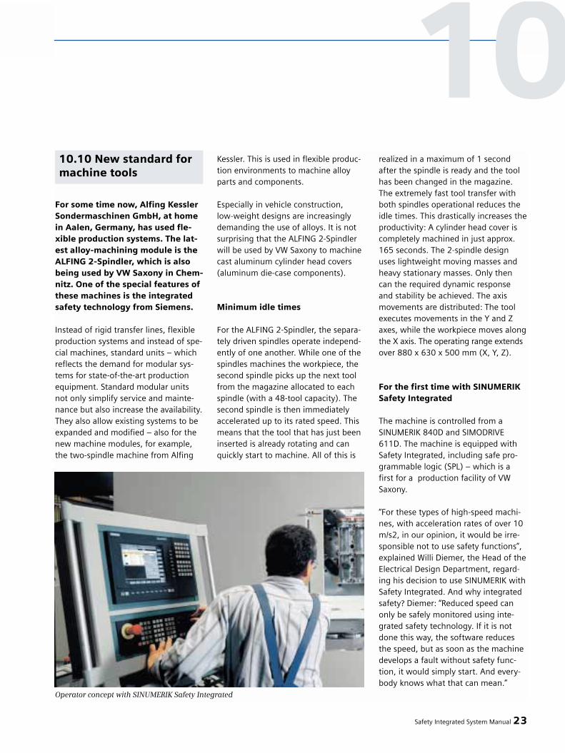
For some time now, Alfing KesslerSondermaschinen GmbH, at homein Aalen, Germany, has used fle-xible production systems. The lat-est alloy-machining module is theALFING 2-Spindler, which is alsobeing used by VW Saxony in Chem-nitz. One of the special features ofthese machines is the integratedsafety technology from Siemens.
Instead of rigid transfer lines, flexibleproduction systems and instead of spe-cial machines, standard units – whichreflects the demand for modular sys-tems for state-of-the-art productionequipment. Standard modular unitsnot only simplify service and mainte-nance but also increase the availability.They also allow existing systems to beexpanded and modified – also for thenew machine modules, for example,the two-spindle machine from Alfing
Kessler. This is used in flexible produc-tion environments to machine alloyparts and components.
Especially in vehicle construction, low-weight designs are increasinglydemanding the use of alloys. It is notsurprising that the ALFING 2-Spindlerwill be used by VW Saxony to machinecast aluminum cylinder head covers(aluminum die-case components).
Minimum idle times
For the ALFING 2-Spindler, the separa-tely driven spindles operate independ-ently of one another. While one of thespindles machines the workpiece, thesecond spindle picks up the next toolfrom the magazine allocated to eachspindle (with a 48-tool capacity). Thesecond spindle is then immediatelyaccelerated up to its rated speed. Thismeans that the tool that has just beeninserted is already rotating and canquickly start to machine. All of this is
realized in a maximum of 1 secondafter the spindle is ready and the toolhas been changed in the magazine.The extremely fast tool transfer withboth spindles operational reduces theidle times. This drastically increases theproductivity: A cylinder head cover iscompletely machined in just approx.165 seconds. The 2-spindle designuses lightweight moving masses andheavy stationary masses. Only thencan the required dynamic responseand stability be achieved. The axismovements are distributed: The toolexecutes movements in the Y and Zaxes, while the workpiece moves alongthe X axis. The operating range extendsover 880 x 630 x 500 mm (X, Y, Z).
For the first time with SINUMERIKSafety Integrated
The machine is controlled from a SINUMERIK 840D and SIMODRIVE611D. The machine is equipped withSafety Integrated, including safe pro-grammable logic (SPL) – which is afirst for a production facility of VWSaxony.
“For these types of high-speed machi-nes, with acceleration rates of over 10m/s2, in our opinion, it would be irre-sponsible not to use safety functions”,explained Willi Diemer, the Head of theElectrical Design Department, regard-ing his decision to use SINUMERIK withSafety Integrated. And why integratedsafety? Diemer: “Reduced speed canonly be safely monitored using inte-grated safety technology. If it is notdone this way, the software reducesthe speed, but as soon as the machinedevelops a fault without safety func-tion, it would simply start. And every-body knows what that can mean.”
Safety Integrated System Manual 23
Operator concept with SINUMERIK Safety Integrated
10.10 New standard formachine tools
10

Safety technology is also required inorder to move the drives with safelyreduced speed even with the protec-tive door open, for example, when themachine is being set-up. Conventionalsafety technology can only disconnectthe power. When a fault develops,Safety Integrated can shut down themachine faster and more safely. It is nolonger absolutely necessary to discon-nect the power. Only drives that reallyhave become uncontrollable are auto-matically disconnected from the powersupply. This provides more safety forthe operator at the decisive instant
and also reduces the mechanical stresson the machine and process. “For Alfing,safe programmable logic triggered usto use this technology”, reported WilliDiemer. “This is because this logicallows conventional switching devicesto be eliminated - which has a positiveimpact - and not only on the price.” A machine equipped with Safety Inte-grated and SPL can be offered at almostthe same price as conventional tech-nology (however, one option is thatthe machine can be operated using the enable button). Furthermore, fewerrelays also mean fewer failures andtherefore a higher degree of safety andhigher machine availability. For instance,if an important relay, for example therelay that enables the pulses or con-troller for the drive, fails, then themachine can no longer brake in a con-trolled fashion. The motor coasts downand there is a chance that the machinecould be badly damaged.
Convincing concept
For the customers from VW Saxony,Safety Integrated with SPL was a newtechnology that they first wanted tocarefully check out. Alfing Kessler wasable to convincingly present the ma-chine, configured according to theSiemens specifications together withthe safety functions, to those responsi-ble at VW Saxony, VW production plan-
ning and representatives from theappropriate German Regulatory Body.The two-channel configuration for allof the safety components in compli-ance with the Siemens specificationswas especially impressive. These safetycomponents included, for example, theprotective doors and Emergency Stopfunction. For this machine, even thecross-circuit monitoring of the twosafety channels was implemented usingthe “4-terminal concept”.
For VW, it was also important that themachine could be operated with theprotective doors open. Using SafetyIntegrated, the machine operator con-cept can be optimally harmonized tothe requirements of the operatingpersonnel and the process itself. Thismakes it far easier to set-up the ma-chine. Tampering, which unfortunatelystill occurs today, is prevented by thebasic concept itself. Additional machinesutilizing the same concept will now bebuilt for VW Kassel, SKODA Auto andDaimlerChrysler.
Willi Diemer is clear about one thing:“For our high-speed machines, we willalways use integrated safety technolo-gy from Siemens.”
24 Safety Integrated System Manual
10 – References
Fewer relays mean fewer failures

State-of-the-art safety when work-ing at machines is a good examplefor how new technologies areestablishing themselves in today'sindustrial environment. They notonly ensure that man and machinecan safety interact with one anoth-er, but also provide high economicbenefits - earlier, this would havebeen a contradiction in terms.
Summary
Increasingly, safety products such aslaser scanners and cameras - that are“electro-sensitive protective equip-ment” are being increasingly used inand on machines to protect persons inhazardous areas. In order to investigateand test these devices, the BG Institutefor Occupational Safety & Health has,for some time now, been using a testsystem with linear axes in an opentype of construction. In order to beable to carry-out the time-consumingseries of tests even faster, more simplyand therefore more efficiently, the testsystem has now been upgraded with“latest state-of-the-art technology”.This includes the integrated safetyfunctions of the Siemens SINUMERIK840D CNC control, a network of all ofthe safety-related system sections viathe Profibus fieldbus with PROFIsafeprofile and four new Siguard LS-4PROFIsafe laser scanners to secure theprotective fields.
Product testing and certificationwith the BG Institute forOccupational Safety & Health
The BG Institute for Occupational Safety& Health is a research and testing insti-tute for a German Regulatory Body (BG).The BG Institute mainly supports thevarious trade organizations and theirinstitutions when it comes to scientifictechnical issues in the area of healthand safety at work by providing thefollowing
• Research, development andinvestigation
• Checking/testing products andmaterial samples
• Carrying-out measurementsin operation and providing support
• Participating in the Standards Asso-ciations and drawing-up regulations
• Providing specialist information and expert know-how.
Further, the BG Institute is activethroughout Europe for manufacturers and companies providing the followingservices:
• Product testing and certification• Certifying quality management
systems.
The BG Institute for Occupational Safety& Health carries-out basic investigation/research work for new types of protec-tive equipment and devices. Not onlythis, it develops testing techniques andworks in the Standards Associations, pro-vides consultation in the product devel-opment process and in actual use and ascertified testing body, tests and certifiesproducts. Presently, it is mandatory thatthese safety-related products are tested.
Safety Integrated System Manual 25
Fig. 10/1
The modernized and automated test system of the BG Institute for Occupational Safety &
Health for and with the latest generation of safety technology makes the product tests spe-
cified by law more efficient – and offers testers themselves “all encompassing safety”
10.11 Safety whentesting products usedfor safety at work
10
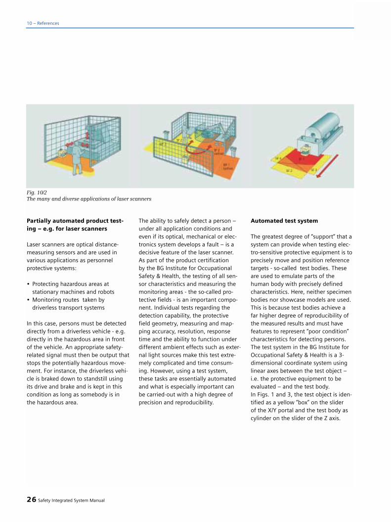
Partially automated product test-ing – e.g. for laser scanners
Laser scanners are optical distance-measuring sensors and are used invarious applications as personnel protective systems:
• Protecting hazardous areas at stationary machines and robots
• Monitoring routes taken by driverless transport systems
In this case, persons must be detecteddirectly from a driverless vehicle - e.g.directly in the hazardous area in frontof the vehicle. An appropriate safety-related signal must then be output thatstops the potentially hazardous move-ment. For instance, the driverless vehi-cle is braked down to standstill usingits drive and brake and is kept in thiscondition as long as somebody is inthe hazardous area.
The ability to safely detect a person –under all application conditions andeven if its optical, mechanical or elec-tronics system develops a fault – is adecisive feature of the laser scanner.As part of the product certification by the BG Institute for OccupationalSafety & Health, the testing of all sen-sor characteristics and measuring themonitoring areas - the so-called pro-tective fields - is an important compo-nent. Individual tests regarding thedetection capability, the protectivefield geometry, measuring and map-ping accuracy, resolution, responsetime and the ability to function underdifferent ambient effects such as exter-nal light sources make this test extre-mely complicated and time consum-ing. However, using a test system,these tasks are essentially automatedand what is especially important canbe carried-out with a high degree ofprecision and reproducibility.
Automated test system
The greatest degree of “support” that asystem can provide when testing elec-tro-sensitive protective equipment is toprecisely move and position referencetargets - so-called test bodies. Theseare used to emulate parts of thehuman body with precisely definedcharacteristics. Here, neither specimenbodies nor showcase models are used.This is because test bodies achieve afar higher degree of reproducibility ofthe measured results and must havefeatures to represent “poor condition”characteristics for detecting persons.The test system in the BG Institute forOccupational Safety & Health is a 3-dimensional coordinate system usinglinear axes between the test object –i.e. the protective equipment to beevaluated – and the test body. In Figs. 1 and 3, the test object is iden-tified as a yellow “box” on the slider of the X/Y portal and the test body ascylinder on the slider of the Z axis.
26 Safety Integrated System Manual
10 – References
Fig. 10/2The many and diverse applications of laser scanners

When dimensioning the protectivefields, the test system has the task ofpositioning the test body in extremelyfine grid steps. The device being testedis then interrogated as to whether itdetects the test body. The many yes/noresults allow a 2 or 3-dimensional imageregarding the protective field geometryto be created therefore identifying pos-sible gaps. If a response time of a pro-tective device is to be measured, thenthe test system moves the test bodywith a variable velocity in the protec-tive field of the device being tested. Itthen evaluates the delay up to its out-put switching signals. This also simu-lates, e.g. a vehicle actually approach-ing a person. In addition to the (four)axes, an “intelligent” control is required
that “handles” all of these test scenar-ios in a coordinated fashion, containsan operator interface for a test pro-gram, which can be used to configurethe test task, test sequence and equip-ment data. It also provides a programarea in which all of this collectedmeasuring data of the equipment/device being tested can be displayedand/or evaluated.
This is complemented by the fact thatthe test system is designed so that it isopen and accessible. And what lookscompletely harmless for positioningmotion to accuracies of millimeters,changes when dynamic test programsare used. In this case, either the test body or the euipment/ device being
tested “flies” through the (test) area at a high speed. Comment: Anotherreason why “live” test objects shouldnot be used! Of course for the BG Insti-tute for Occupational Safety & Health,safety always comes first. A hazardanalysis was carried-out just the sameas for securing areas at machines indu-stry, and the areas of the axes thatcould cause injury were carefully pro-tected and secured. And it should be of no surprise - using laser scanners.
The latest generation of laserscanners
In the test system, four Siguard LS-4PROFIsafe laser scanners with protectivefields SF1 to SF4 (shown in a simplifiedfashion in Fig. 10/3) provide perfect per-sonnel protection in the axis traversingranges. The laser scanners are directlyconnected to Profibus with the PROFIsafeprofile via an integrated interface. Bythe way, the BG Institute for Occupatio-nal Health & Safety also certified thelaser scanner that is suitable for appli-cations up to Category 3 according toEN 954-1. This means that what waspreviously a device being tested, is nowoperational in the test system providingthe optimum degree of safety.
Safety Integrated System Manual 27
Fig. 10/3Schematic representation of the axis protective field (view from the top)
Fig. 10/4New SIGUARD LS-4 PROFIsafe laser scan-ners – simple, reliable installation usingthe integrated Profibus interface
10

Simple installation using a directconnection to Profibus
Profibus with the PROFIsafe profile wasselected to establish the connection be-tween the laser scanners and the safety-related system control – the SINUMERIK840D. It establishes the direct connec-tion to the laser scanners as well as to all of the other safety-related plant sec-tions. These include, for example, theEmergency Stop command devices,operating mode key-operated switchesand holding brakes. These are directlyconnected to the fail-safe SIMATIC ET200S input/output modules withoutrequiring any additional devices there-fore minimizing costs. Of course all ofthis has the positive spin-off that engi-neering and installation costs are alsosignificantly reduced.
Additional safety integrated in thecontrol/drive system
The test system was automated with a CNC control already back in 1996.Even then, the SINUMERIK 840D usedhad integrated safety functions. Thefunctional scope included (just thesame as today) standstill, velocity andposition and endstop monitoring thatcould be parameterized (!) Additional,functions are used on and in the testsystem in the form of the current SINU-MERIK Safety Integrated safety package;these are as follows:
• Safe programmable logic (SPL)All of the safety-related sensors andactuators are directly connected to theI/O of the control without using anyexternal evaluation devices. They areevaluated in the software. This safety-related functionality realized in thesoftware results in a high degree offlexibility when implementing plantoperator control philosophies in line
with those required in practice. Further,high cost-saving benefits are obtained by substituting conventional hardwarecomponents.
• Expanded stop functionsWith the introduction of the “externalstop” function, it has been possible tooperate parts of the test system withoutany interruption or to simply continueoperation even when safety signalshave responded. For example, if a per-son (generally accidentally and uninten-tionally) or the test engineer himselfenters the protective field during thetest - as example, one of the protectivefields 2 or 3 (SF2/SF3 in Fig. 10/3) thenthe velocity of the portal slider (axesX/Y) is reduced to a “safely-reducedspeed”; however, it doesn't remain sta-tionary - that would disturb production -and does not result in the program
being interrupted. This means that thetest engineer doesn't have to wait forthe program to start again before con-tinuing the test - however, safety is stillabsolutely provided in every situation.The reason for this is that also for the Zslider, depending on its particular posi-tion at any time, an intelligent decisionis made as to whether it must stoppedto a standstill or the safely reducedspeed activated.
• Expanded status and diagnosticsdisplay
In order to provide fast and basic diag-nostic functionality, the required infor-mation about the status of the safetyfunctions in the system can be directlydisplayed using a softkey bar. Further,graphic, application-specific diagnosticstatus screens are integrated in theoperator control panels.
28 Safety Integrated System Manual
10 – References
Fig. 10/5
Profibus with PROFIsafe profile to network all the safety components results in a
simple system installation

• Integrated acceptance testThe safety functions of electric drivesare to be tested when commissioningusing an acceptance test according tothe specifications of the applicablestandards. A “tool” has been integratedinto the control/drive system to allowusers to carry-out this test as simplyand quickly as possible. This signifi-cantly reduces the acceptance timesas, e.g. relevant machine data can beautomatically transferred. The prompt-ed tested sequence with plain text dis-play also simplifies operator control.Even the acceptance report required isautomatically generated.
Operating experience: The highestdegree of flexibility, availabilityand safety
When operating a (test) machine thatbehaves, depending on the situation, ina specific, safety-related fashion “givesa good impression” from the perspec-tive of a test engineer. This means thathe is not confronted with tedious inter-ruptions, or has to start from the verybeginning when, as a result of the newstop functions, he inadvertently ordeliberately enters the hazardous areawhen testing a piece of protectiveequipment. The requirement for simplehandling and fast (test) sequences wastherefore fulfilled. This means that thisstate-of-the-art safety technology reallyprovides the highest degree of flexibili-ty and availability and at the same time,the best possible personnel protection– “Safety (really is) integrated”!Torsten BorowskiBG Institute for OccupationalHealth & Safety; Saint AugustinGroup 5 “Accident Protection”Peter KeilSiemens AG, Erlangen – A&D MC,Automation and Drives, Motion Control
Safety Integrated System Manual 29
Fig. 10/6
Software replaces hardware components, electrical cabinets become smaller
Fig. 10/7
Integrated acceptance test with operator prompting and plain text display as proof for
machinery construction companies and end users
Afterwards Beforehand
10

Safety Integrated for complex,special machine tools
Time is money. If you want to stay in the black when producing partsor you wish to reduce costs thenspeed is of essence. The sophisticat-ed machine concepts from AugustWenzler GmbH in Spaichingen per-mit cycle times to be achieved fortheir rotary transfer machines formachining large batches whichsome can only dream about.Innovative solutions are also indemand when it comes to safetytechnology. With the three largerotary cycle machines that Opelordered from the Wenzler compa-ny, "Safety Integrated' celebrateda successful entry.
Using its technology, the Wenzler com-pany produces complex, precisionworkpieces, for example, automobilechassis components. For the casebeing considered, wheel hub carriersand pivot axes are machined from alu-minum with a unit machining time ofonly 17 seconds. This time is a realbenchmark. This is complemented byother features such as a favorableprice-performance ratio, the fact thatthe machines can be flexibly set-upand the experience which Wenzler hasalready gained in other projects in theautomobile industry. All of these factstogether convinced Opel to awardWenzler the three large rotary cyclemachines to machine their chassiscomponents. Not only this, eachmachine has 72 NC axes which alsoisn't an everyday occurrence - even forthe high-tech Wenzler company.
The machine, in its present version,was developed in various phases overthe last 20 years.
From 1983 onwards, the machine wasequipped with a CNC control systemwhich Wenzler themselves had devel-oped. At the end of the nineties, Wenz-ler changed-over to using Siemenscontrol systems.
Today, Wenzler has about 70 employ-ees and constructs between 8 and 10 machines per year. Most of thesemachines are supplied to the automo-bile industry. The value of such largemachines can easily reach between 1.5 and 2.5 million Euro, depending on the actual version.
High degree of productivity in thetightest space
The Wenzler MSC-8 B (multi-spindlecenter) is an 8-station machine. The 8 workpieces can be simultaneouslymachined by up to 14 tools.
The workpieces are mounted on satel-lite tables that can be swiveled so that5-side machining - or by automaticallyturning-over - 6-side machining is alsopossible. Thanks to its rigid modularity,this flexible cell has the character of astandardized rotary interlinked machinewith the performance of a special-pur-pose machine. Each movement is CNCcontrolled so that the full flexibility ofthe machine can be utilized in a ma-chining cube of 400 x 400 x 400 mm.The central element is the 8-cornerdrum. This is suspended and supportsthe workpiece - is suspended. Thisguarantees optimum chip flow andgood accessibility of the drum bearingand clamping equipment.
On the electrical side, the MSC-8B isequipped with the Siemens Sinumerik840D machine control, and the match-ing Simodrive 611D digital drives, 1FT6permanent-magnetic synchronousmotors and the Profibus fieldbus. Thisis complemented by a series of distrib-uted units. Just recently, Wenzler hasalso started to use the integrated safetyfunctions “SINUMERIK Safety Integrated”.
Integrated safety technology
About five years ago, Siemens was thefirst drive manufacturer worldwidewith integrated safety functions forpersonnel and machinery protection.
By integrating the safety functions, thedrive system and the CNC control alsohandle the safety functions in additionto the control itself. The sa-fety func-tions include safely monitoring thespeed, standstill and position as well as functions to logically combine sig-nals in a safety-related fashion.
The logical operations and responsesare realized within the system. All sa-fety-related faults in the system alwaysresult in the potentially hazardousmotion being safely shut down and thepower to the motor being contactlesslyinterrupted. Motion is always stopped,optimally adapted to the state of themachine. When setting-up, this meansa high degree of protection for person-nel and additional protection for themachine, tool and workpiece in theautomatic mode.Safety Integrated is already in use inover 13.500 machines with over 80.000drives. Machinery manufacturers canaccess a considerable amount of know-how when it comes to engineeringnew safety concepts.
30 Safety Integrated System Manual
10 – References
10.12 A synthesis ofspeed & safety

For the Opel machines from Wenzler,this involved 72 CNC axes and a total of99 drives per machine. This presentedboth Wenzler as well as Siemens withnew challenges - especially becausealmost all of the Safety Integrated func-tions, including the safe brake manage-ment as protection against vertical axesfalling were to be implemented on thesemachines.
The Opel project
The Wenzler machines were used inthe Opel project to produce aluminumhub carriers and pivot axes. Each typein the left/right versions is simultane-ously machined so that after 4 work-pieces, the components required for 1 automobile have been produced.Aluminum hub carriers and pivot axesare relatively new in chassis construc-tion. Previously, Opel manufacturedthese parts out of gray cast iron. Theperformance and ride comfort of ve-hicles are improved by reducing theweight, especially the unsprung mass-es. The new aluminum version wasable to reduce the weight by 6.6 kg.“The project was kicked-off in lateAutumn 2000. In cooperation withWenzler, a rough concept was initiallydrawn-up which indicated as to howsuch extensive safety integrated appli-cations could be even approached”,explained Ingrid Hölzer who wasresponsible on the Siemens side forthis task. This concept used the controlstructure defined by the Wenzler com-pany, which comprised eight NCUs.NCU1 was defined as master for theSafety Integrated functionality. Thespecialists from Wenzler - namely RalfRottler - wrote the software for the NCand the PLC sections of the control.“This was extremely successful”explained Ingrid Hölzer. Communi-
cations down to the level of the set-ting-up technicians was fantastic”.
Higher degree of protection andflexibility
The advantages which Wenzler nowsees, explained Jürgen Ruffieux, headof the electronics development depart-ment, “primarily in a higher degree ofprotection during the setting-up opera-tion as well as in the higher flexibilityfor the setting-up personnel.” Previously,
safety devices and equipment had tobe bypassed when setting-up themachine – this is now a thing of thepast. The setting-up technicians arealways protected.Using Safety Integrated, Opel expectedlower costs when installing the machine,shorter response times and a higherdegree of safety due to automatic self-diagnostics and the crosswise monitor-ing using the PLC and NC. The newmachines went into series productionin the first quarter of 2002.
Safety Integrated System Manual 31
The MSC- 8B - a modular, rotary cycle machine that for Opel is equipped with 72 NC axes.
The “naked” machine shows the design comprising individual and similar basic elements
Aluminum reduces the weight of an automobile. In this particular case with Opel, these
aluminum wheel hub carriers and pivot axes reduce the weight by 6.6 kg with respect to
cast iron parts
10

Increasing productivity and a highdegree of cost consciousness in theprinting machine industry is resultingin the fact that classic mechanical so-lutions (for example, line shafts) arebeing replaced by electric drives(mechatronics). On the other hand,this places higher demands on thesafety technology which is used tomonitor the drive. Previously, only afew drives had to be monitored fromthe safety aspect, whereas today, newconcepts mean that many drives haveto be incorporated in the monitoringsystem.
An especially high potential hazard iswhen operating personnel have towork on a printing machine with theprotective devices open. Here, legisla-tion demands that personnel must beprotected against the drives undesir-ably starting by using suitable devices.
SIMOVERT MASTERDRIVES drives sup-port this protective function. This pre-vents drives undesirably starting usingan integrated safety relay. This meansthat the contactor on the motor sidethat was previously used can be elimi-nated. In the printing machine indus-try, systems with well over 100 drivesare no longer a seldom occurrence.Significant time and cost savings wereachieved by eliminating material andinstallation costs and due to the lessspace required in the control cabinet.
32 Safety Integrated System Manual
10 – References
10.13 Safe standstill inthe printing industry

Safety Integrated System Manual 33
10


Terminology
Actuator
An actuator converts electrical signalsinto mechanical or other non-electricalquantities.
Blanking
Using blanking, a specified section orarea is suppressed from a protectivefield, e.g. a light curtain or light grid,i.e. it is disabled. There are two typesof blanking: Fixed and floating blanking.
Fixed blanking
For fixed blanking, the selected area orrange is fixed. This function is used, forexample, if fixed objects protrude intothe protective field.
Floating blanking
Floating blanking permits that normal-ly one or two light beams in a protecti-ve field are interrupted without a stopsignal being output from a light cur-tain. This function is required if the“permissible” interruption of the lightbeams does not refer to a fixed posi-tion in the protective field, e.g. if amoving cable enters the protective field.
Category
In EN 954-1 (prEN ISO 13849-1) this is used to “classify the safety-relatedparts of a control with reference totheir immunity to faults and theirbehavior under fault conditions whichis achieved as a result of the structuralarrangement of the parts and/or theirreliability.”
Channel
Element or group of elements thatexecutes a function independently.
2-channel structure
Structure that is used to achieve faulttolerance.
For example, a 2-channel contactorcontrol can be achieved if at least twoenable circuits are available and themain current can be redundantly swit-ched-off or a sensor (e.g. EmergencyStop switch) is interrogated using twocontacts that are then separately con-nected to evaluation unit.
Danger
Potential source of damage. (from EN 292-1 or ISO 12100-1)
e.g. danger due to electric shock,danger due to crushing, ...
Emergency Stop
An operation in an emergency that isdesigned to stop a process or move-ment that is potentially dangerous(from EN 60204-1 Annex D).
EMERGENCY SWITCHING-OFF
Emergency Switching-off equipment
Arrangement of components that areintended to implement an Emergency Stop function (EN 418 orISO 13850). (Note: Today, a differentia-tion is made between “Stopping in anemergency” and “Power off in an emer-gency”.
Stopping in an emergency
A function which either avoids or mini-mizes impending or existing danger forpersons, damage to the machine orwhen carrying out work;
– initiated by a single action of a person.(EN 291-1 or ISO 12100-1)
Power off in an emergency
Power off in an emergency is achievedby disconnecting the machine from thesupply subsequent to a Category 0stop (EN 60204 1997). Power off in an emergency should be provided, incompliance with EN 60204-1 1997, where there is the possibility of dangerdue to electricity (electric shock).
2 Safety Integrated System Manual
11 Appendix
11.1 Terminology andabbreviations

Enabling device
Additional manually actuated controldevice that permits a specific functionof a machine if it is continually actua-ted.
Fail-safe
The capability of a control to maintaina safe condition of the controlledequipment (e.g. machine, process), or to bring this into a safe conditionwhen faults occur (failures).
Failure/fault
Failure
When a piece of equipment or a deviceis no longer capable of executing aspecific function.
Fault
Unintentional status of a piece ofequipment or device which is charact-erized by the fact that it is not capableof executing a specified function.
Note: “Failure” is an event and “Fault” is a condition.
Fault
Refer to “Failure / fault”.
Fault tolerance
Fault tolerance N means that a piece ofequipment or device can still execute the specified task even when N faultsare present. For N+1 faults, the pieceof equipment or device fails when exe-cuting the specified function.
Feedback circuit
Circuit to monitor controlled contactors.
The function of contactors can bemonitored by reading back the positi-vely driven auxiliary contacts by anevaluation unit. If the contactor con-tacts are welded, the evaluation unitprevents a restart.
Functional safety
Part of the safety of a piece of equip-ment or device (e.g. machine, plant,which depends on the correct func-tion.
Load group
A group of motor starters that is supp-lied through a power bus. A load groupcan be located within a potential groupor can include parts of two potentialgroups.
Motor starter (MS)
Motor starters include direct and rever-sing starters. Starting and direction ofrotation are determined using a motorstarter.
Direct starter
A direct starter is a motor starter forone direction of rotation, which direct-ly powers up or powers down a motor.It comprises a circuit-breaker and acontactor.
Reversing starter
A reversing starter is a motor starter fortwo directions of rotation. It comprisesa circuit-breaker and two contactors.
Muting
Muting disables one or several safetyfunctions for a limited time in line withspecifications
Partial potential group
A partial potential group exists if with-in a potential group, the auxiliary vol-tage can be partially switched out.
Potential group
A group of motor starter and/or elec-tronic modules which is supplied froma power module.
Safety Integrated System Manual 3

Redundancy
Availability of resources or equipmentmore than is actually required for itsexecution.
Requirement Class (AK)
Measure of the safety-related perfor-mance of control equipment. Definedin DIN V 19250 and DIN V VDE 0801.
Risk
Combination of the probability of theoccurrence of damage and the extentof the damage.
Safety
Freedom from unacceptable risk.
Safety function
Function (e.g. of a machine or a con-trol) whose failure (or breakdown) can increase the risk(s).
Safety functions of controls (EN 954 or prEN ISO 13849-1)
“A function, initiated by an input signaland processed by safety-related partsof controls that allows the machine toachieve a safe condition (as system).”
Safety goal
To keep the potential hazards for manand the environment as low as possi-ble without restricting industrial pro-duction, the use of machines or theproduction of chemicals as far as ab-solutely necessary.
Safety Integrity Level (SIL)
In IEC 61508, this is defined as themeasure for the safety performance of electrical or electronic control equipment. (-> Section 1)
Safety-related control function(IEC 62061)
Control function that is executed by asafety-related control system in orderthat a system goes into a safe condi-tion (e.g. machine) or to avoid hazar-dous conditions occurring.
Safety-related control function
Slightly differing definitions are provi-ded in the various Standards.
Stop
This is a function that is intended toavoid or minimize hazards to person-nel, damage to the machine or theexecution of operational processes. It has priority over every other opera-ting mode.
Stop Category
A term which is used in EN 60204-1 to designate three different stoppingfunctions.
Two-hand circuit
Control device, which requires that it issimultaneously actuated by both handsin order to activate hazardous machinefunctions and also maintain them.
4 Safety Integrated System Manual
11 – Appendix

Abbreviations
ANSI American National Standards Institute
BGIA German Technical Inspectorante
BWS Electro-sensitive protective devices
CNC Computerized Numerical Control
CPU Central Processing Unit
DMS Direct measuring system
FTS Driverless transportation system
HMI Human Machine Interface
IBS Commissioning
IMS Indirect Measuring System
KDV Cross-checking
MRPD Machine Readable Product Designation: Order No. ofSiemens components
NC Numerical Control
NCK Numerical Control Kernel
NCU Numerical Control Unit
NFPA National Fire Protection Association
OP Operator Panel
OSHA Occupational Safety and Health Administration
PLC Programmable Logic Control
PM Positive-ground switching
PP Positive-positive switching
S5 SIMATIC S5
S7 SIMATIC S7
Safety Integrated System Manual 5

[1] Position paper DKE 226.0.3: Safety-related functionselectric drive systems in machines. Status 1/98.
[2] Schaefer, M.; Umbreit, M.: Drive systems and CNC controls with integratedsafety. BIA Report No. 4/97
[3] Categories for safety-related controls acc. toEN 954-1. BIA Report 6/97.
[4] ZH1/419. Testing and certificationregulations of the testing andcertification bodies in BG-Prüfzert.Edition 10/1997.
[5] Reinert, D.;Schaefer, M.; Umbreit, M.: Drives and CNC controlswith integrated safety. In: ETZ-Heft 11/98
[6] Safety-related data transfer; requirements as well as deterministic and probabilistictechniques; 1998, Uwe Jesgarzewski, Rainer Faller – TÜV Product Service
Internet address:
General information
http://www.siemens.de/safetyhttp://www.siemens.de/automation
AS-Interface
http://www.siemens.de/as-interface
SIRIUS
http://www.siemens.de/sirius
SIGUARD
http://www.siemens.de/siguard
SIMATIC
http://www.siemens.de/simatic-controllerhttp://www.siemens.de/simatic-dp
SIMODRIVE 611, SIMODRIVE POSMO,SIMOVERT MASTERDRIVES
http://www.siemens.de/simodrive
SINUMERIK
http://www.siemens.de/sinumerik
Hotlines:
SIMATIC++49(0)911-895-7000
SIRIUS++49(0)911-895-5900
SINUMERIK++49(0)180-5258008
6 Safety Integrated System Manual
11 – Appendix
11.2 References 11.3 Contact – InternetHotlines

Because training is decisive foryour success
SITRAIN® - the Siemens Training forAutomation and Industrial Solutions -is there to support you in mastering all of your tasks.
With training from the market leader in automation, plant erection and sup-port, you can certainly win when it co-mes to feeling comfortable in makingthe right decision. Especially when itinvolves optimally using products andefficiently using plants and systems.You can eliminate performance issuesand problems in existing plants andsystems and reliably exclude expensiveplanning mistakes from the very start.
When all is said and done, this sig-nifies enormous benefits for youroperation: Shortened start-uptimes, optimized plant and systemsections, fast troubleshooting,lower downtimes. The result - ahigher degree of profitability andlower costs.
Top trainers
Our trainers have in-depth experiencein the field and also extensive didacticexperience. Personnel that developthese training courses have a directlink to our product development groupsand they directly pass on their know-ledge to the trainers.
In-line with that required in practice
Because our trainers are very much intouch with what is required in practice,means that they can really communica-te theoretical knowledge. But as everyo-ne knows, theory can be somewhatdull, and this is why we place the hig-hest significance on practical training -that represents up to halve of the cour-se time. This means that you can imme-diately implement what you have lear-ned in your day-to-day business. Thetraining courses use training equipmentthat has been specifically developed for
this purpose so that you feel absolutelyconfident in our training courses.
Wide variety of courses
We have a total of approximately 300courses and provide training for thecomplete range of A&D products andto a large extent, plant solutions fromI&S. Off-site training courses, self-lear-ning software and moderated seminarsin the web complement our classicrange of courses.
Close to the customer
We are never far away. We are represent-ed approximately 60 times in Germanyand worldwide in 62 countries. Wouldyou like personalized training insteadof participating in our 300 courses?Our solution: We can tailor the trainingto your personal requirements.
We provide training courses in our trai-ning centers or also in your facility.
Safety Integrated System Manual 7
11.4 Seminars availablefor safety technology,Standards and Directives
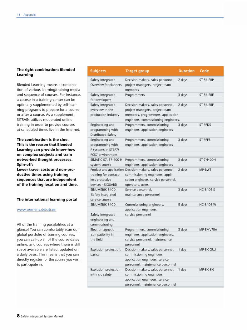
The right combination: BlendedLearning
Blended Learning means a combina-tion of various learning/training mediaand sequence of courses. For instance,a course in a training-center can beoptimally supplemented by self-lear-ning programs to prepare for a courseor after a course. As a supplement,SITRAIN utilizes moderated onlinetraining in order to provide courses at scheduled times live in the Internet.
The combination is the clue. This is the reason that BlendedLearning can provide know-how on complex subjects and train networked thought processes.Spin-off: Lower travel costs and non-pro-ductive times using trainingsequences that are independent of the training location and time.
The international learning portal
www.siemens.de/sitrain
All of the training possibilities at aglance! You can comfortably scan ourglobal portfolio of training courses,you can call-up all of the course datesonline, and courses where there is stillspace available are listed, updated on a daily basis. This means that you candirectly register for the course you wishto participate in.
8 Safety Integrated System Manual
11 – Appendix
Safety Integrated Decision-makers, sales personnel, 2 days ST-SIUEBP
Overview for planners project managers, project team
members
Safety Integrated Programmers 3 days ST-SIUEBE
for developers
Safety Integrated Decision makers, sales personnel, 2 days ST-SIUEBF
overview in the project managers, project team
production industry members, programmers, application
engineers, commissioning engineers,
Engineering and Programmers, commissioning 3 days ST-PPDS
programming with engineers, application engineers
Distributed Safety
Engineering and Programmers, commissioning 3 days ST-PPFS
programming with engineers, application engineers
F systems in STEP7/
PCS7 environment
SIMATIC S7, S7-400 H Programmers, commissioning 3 days ST-7H400H
system course engineers, application engineers
Product and application Decision-makers, sales personnel, 2 days MP-BWS
training for contact- commissioning engineers, appli-
less protective cation engineers, service personnel,
devices - SIGUARD operators, users
SINUMERIK 840D, Service personnel, 3 days NC-84DSIS
Safety Integrated maintenance personnel
service course
SINUMERIK 840D, Commissioning engineers, 5 days NC-84DSIW
application engineers,
Safety Integrated service personnel
engineering and
commissioning
Electromagnetic Programmers, commissioning 3 days MP-EMVPRA
compatibility in engineers, application engineers,
the field service personnel, maintenance
personnel
Explosion protection, Decision makers, sales personnel, 1 day MP-EX-GRU
basics commissioning engineers,
application engineers, service
personnel, maintenance personnel
Explosion protection Decision makers, sales personnel, 1 day MP-EX-EIG
intrinsic safety commissioning engineers,
application engineers, service
personnel, maintenance personnel
Subjects Target group Duration Code

Safety Integrated System Manual 9
In this overview course, you will learnabout everything that is required toplan a safe plant or system. You willget to know the appropriate legislationand Standards and understand how totransfer the resulting contents into youplant or system planning.
Contents
• Overview, legislation/standards• Risk analysis, SIL Categories, Per-
formance Levels, Safety Category• Functional safety MM• Application software development,
V model• Tasks of somebody that is
responsible for functional safety
Safety Integrated Overview for Planners (ST-SIUEBP)
• Documents that must be reques-ted or must be supplied, revision procedures
• Fault evaluation• Probability of failure• Qualifying the complete system
- application examples with exercises• Common Cause faults• State-of-the-art safety-relevant
systems• Siemens solutions for machinery
and process control
Target groups
Decision makers, sales personnel, pro-ject managers, project team members
Duration
2 days
Course fee
On request
Course location
Mannheim
In this course, in addition to the con-tents of the overview course (ST-SIUEBP)you will obtain additional informationregarding calculations required whenplanning a safe plant or system. Theknowledge that is theoretically taughtwill be gone into more depth in exam-ples and exercises that are in line withwhat is encountered in the field.
Contents
• Overview, legislation/standards• Risk analysis, SIL Categories, Per-
formance Levels, Safety Category• Functional safety MM• Application software development,
V model• Tasks of somebody that is responsible
for functional safety
Safety Integrated Overview for Development Engineers (ST-SIUEBE)
• Documents that must be requested or must be supplied, change requests
• Fault evaluation• Probability of failure• Qualifying the complete system• Application examples with exercises• Common Cause faults• State-of-the-art safety-relevant
systems• Siemens solutions for machinery
and process control• FMEDA (Failure Modes, Effects and
Diagnostic Analysis)• ULM for safety technology• Qualification, Common Cause• Markov models• Basic system structures• Examples and exercises
Target group
Programmers
Duration
3 days
Course fee
On request
Course location
Mannheim

10 Safety Integrated System Manual
11 – Appendix
This course provides you with the cur-rent situation as far as standards areconcerned in production technology.You will also get to know how to cor-rectly apply it in practice using selectedexamples. The objective of this courseis to merge theory and practice. Youwill secure a high production qualityand achieve competitive advantages bycompetently implementing this know-ledge in your own operation.
Contents
• EC Machinery Directive- Basics, definitions, requirements,
implementation, application on new machines and new machine equipment
- Use when making modifications and upgrading
Safety Integrated, Overview in Production Technology (ST-SIUEBF)
- Evaluating conformity• EC Directive
- Basic, definitions, requirements, implementation
• Overview of the Standards- EN ISO 12 100 (EN 292),
EN 1050 (ISO 14121)- EN 60204-1- EN 954-1, (prEN ISO 13849-1),
EN ISO 13849-2, (EN 954-2)- EN 62061, IEC 61508
• Example from the field - automobile industry (paint shop, subsequenthandling with transport using a rail-based system)- Standards and use- Applications- Configuration/design and imple-
mentation of the risk analysis using conventional wiring and bus-basedsolutions.
Target group
Decision makers, sales personnel,project managers, project team mem-bers, programmers, commissioningengineers, users
Duration
2 days
Course fee
On request
Course location
Nuremberg, Mannheim
Participants learn how to handle, engi-neer, program, commission, diagnoseand troubleshoot distributed safetysystems. This includes the fail-safeCPUs 315F-2DP, CPU 317F-2DP, CPU416F DP and the IM151-F CPU. The F-FBD and/or F-LAD programming lang-uages are used for the fail-safe pro-gram generation.
Contents
Overview, Standards and Directives• AS S7-300F (principle, system design
and I/O)• Engineering fail-safe I/O with
distributed safety
Engineering and programming with Distributed Safety (ST-PPDS )
• Programming a safety-relateduser program
• Fail-safe communicationsPROFIsafe (CPU-CPU communications, Master-slave communications)
• Diagnostic capability (CPUdiagnostics, I/O diagnostics, other diagnostic tools)
• Exercises on configuring the I/O, communications, troubleshooting
• Examples for programming(Emergency Stop, protective door, safety-related shutdown, passiva-tion, special programming issues)
Target groups
Programmers, commissioning engi-neers, application engineers
Duration
3 days
Course fee
On request
Course location
Essen, Hanover, Mannheim,Nuremberg
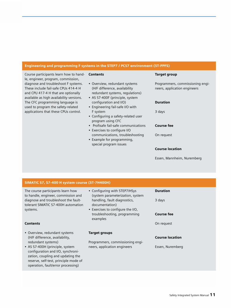
Safety Integrated System Manual 11
Course participants learn how to hand-le, engineer, program, commission,diagnose and troubleshoot F systems.These include fail-safe CPUs 414-4 Hand CPU 417-4 H that are optionallyavailable as high availability versions.The CFC programming language isused to program the safety-relatedapplications that these CPUs control.
Engineering and programming F systems in the STEP7 / PCS7 environment (ST-PPFS)
Contents
• Overview, redundant systems(H/F difference, availabilityredundant systems, regulations)
• AS S7-400F (principle, system configuration and I/O)
• Engineering fail-safe I/O with F system
• Configuring a safety-related user program using CFC
• Profisafe fail-safe communications• Exercises to configure I/O
communications, troubleshooting• Example for programming,
special program issues
Target group
Programmers, commissioning engi-neers, application engineers
Duration
3 days
Course fee
On request
Course location
Essen, Mannheim, Nuremberg
The course participants learn how to handle, engineer, commission anddiagnose and troubleshoot the fault-tolerant SIMATIC S7-400H automationsystems.
Contents
• Overview, redundant systems(H/F difference, availability, redundant systems)
• AS S7-400H (principle, system configuration and I/O, synchroni-zation, coupling and updating the reserve, self-test, principle mode of operation, fault/error processing)
SIMATIC S7, S7-400 H system course (ST-7H400H)
• Configuring with STEP7/HSys (system parameterization, systemhandling, fault diagnostics, documentation)
• Exercises to configure the I/O, troubleshooting, programmingexamples
Target groups
Programmers, commissioning engi-neers, application engineers
Duration
3 days
Course fee
On request
Course location
Essen, Nuremberg

12 Safety Integrated System Manual
11 – Appendix
In this workshop you will learn how to handle and use electro-sensitiveprotective devices (light curtains, lightgrids and laser scanners) belonging tothe SIGUARD series.
Contents
• European Directives• Safety-related parts of controls
acc. to EN 945-1• SIGUARD safety light curtains• SIGUARD safety laser scanners• Calculating safety distances and
clearances acc. to EN 999• Evaluation units• Testing electro-sensitive protective
devices • Diagnostics
Product and application trainingfor contactless protective devices - SIGUARD (MP-BWS)
Target group
Decision makers, sales personnel,commissioning engineers, applicationengineers, service personnel, opera-ting personnel, users
Duration
2 days
Course fee
On request
Course location
Mannheim, Nuremberg-Moorenbrunn
This course provides participants withknowledge and skill sets that are requi-red to service and maintain a machineequipped with SINUMERIK 840D andSafety Integrated. After participating inthe course, course participants cantroubleshoot and resolve faults. Afterrepair/software upgrades, course parti-cipants can check the safety-relatedfunctions and accept them.
Contents
• General information on safety-related systems
• System prerequisites• Description of the basic safety-
related functions
SINUMERIK 841D, Safety Integrated Service&Maintenance course (NC-84DSIS)
• Safe programmable logic• Connecting sensors/actuators• Test stop• Description of the machine data
and interface signals• Procedure when commissioning and
troubleshooting• Evaluating diagnostic and alarm
displays• Circuit examples for Safety Integrated• Acceptance report• Practical training exercises on fault
finding and service at training modelsequipped with digital feed and main spindle drives
Target groups
Service personnel, maintenance per-sonnel
Duration
3 days
Course fee
On request
Course location
Chemnitz, Düsseldorf, Nuremberg-Moorenbrunn

Safety Integrated System Manual 13
This course shows participants how to engineer and commission the SafetyIntegrated functionality with a SINU-MERIK 840D. After the course, partici-pants can engineer, test and commis-sion the Safety Integrated function anda SINUMERIK 840D special system con-figuration with safety-related functions.
Contents
• General information on safety-related systems
• System prerequisites• Description of the basic relevant
function• Safe programmable logic
SINUMERIK 840D, Safety Integrated Engineering and Commissioning (NC-840DSIW)
• Connecting sensors/actuators• Test stop• Safety-related communications
with PROFIsafe• Safe brake management• Description of the machine data
and interface signals• Procedure when commissioning
and troubleshooting• Evaluation of diagnostic and
alarm displays• Circuit examples for Safety Integrated• Acceptance report• Practical exercises to engineer,
commission and service equipmenton training models equipped withdigital feed and main spindle drives
Target groups
Commissioning engineers, applicationengineers, service personnel
Duration
5 days
Course fee
On request
Course location
Nuremberg-Moorenbrunn
This course addresses all personnel indevelopment, mechanical design, pro-duction and service that require practi-cal know-how and skill sets regardingEMC for their day-to-day work. Videofilms on the individual subjects showthe effects of EMC phenomena in prac-tice with the appropriate measures toprevent them or resolve them. Theobjective of this training course is tolearn how to avoid or resolve EMCfaults.
Contents
• What you have to especially observewhen planning plants
• What an EMC correct electricalcabinet looks like, especially withvariable-speed drives, backgroundinformation on the individual cabi -net design rule and regulations
• How a differentiation can be made between software, hardware and
Electromagnetic compatibility in the field (MP-EMVPRA)
EMC faults and disturbances• Which test equipment makes sense
when troubleshooting and how it isused
• Tips and tricks when trouble- shooting - how you can subsequent-ly increase the noise immunity
• Causes, effects and counter-measures relating to static discharge
• The disadvantages and advantagesof different grounding techniques,what are the causes of potentialdifferences, how is potential bondingimplemented
• What causes harmonics, their effectsand how they can be avoided, line resonance effects, reactor circuits, blocking circuits etc.
• When can filters be used and how• Everything about connecting cable
shields• Motor bearing currents, what causes
them, effects, counter-measures• Aspects relating to lightning
protection, from identifying thehazard up to using protective ele-ments
• Introduction into the various Standards, CE, caution, new EMC Directive!
Target groups
Programmers, commissioning engi-neers, application engineers, servicepersonnel, maintenance personnel
Duration
3 days
Course fee
On request
Course location
Refer to the Internet
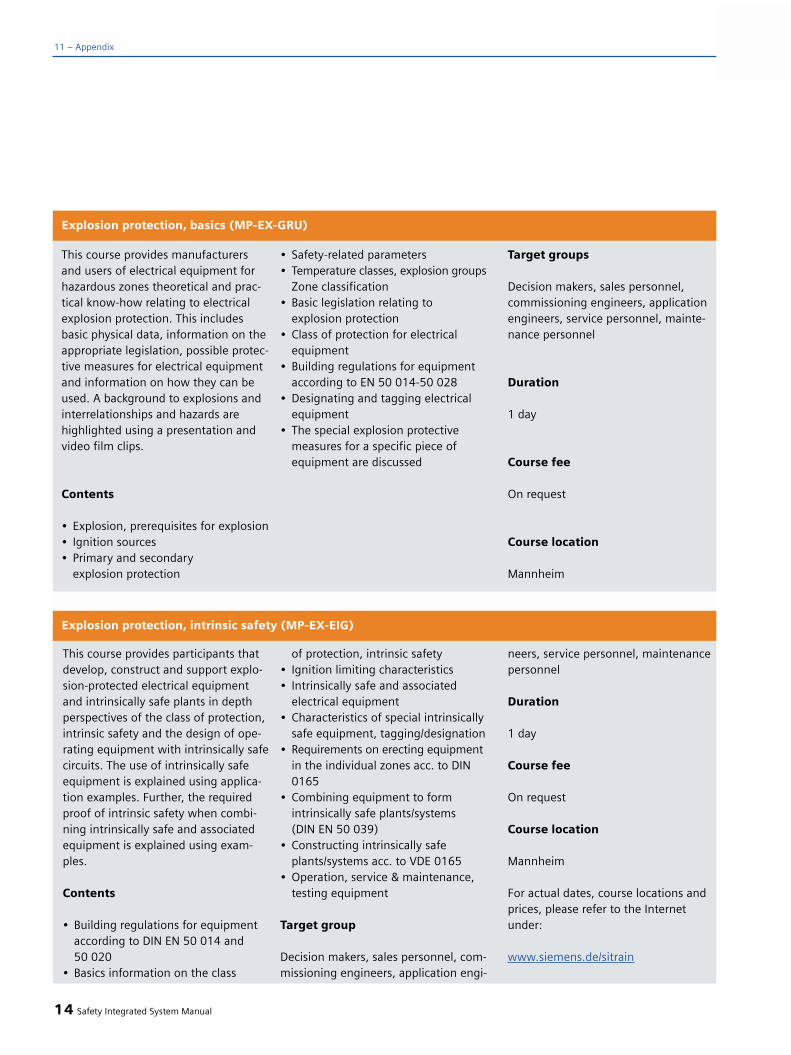
14 Safety Integrated System Manual
11 – Appendix
This course provides manufacturersand users of electrical equipment forhazardous zones theoretical and prac-tical know-how relating to electricalexplosion protection. This includesbasic physical data, information on theappropriate legislation, possible protec-tive measures for electrical equipmentand information on how they can beused. A background to explosions andinterrelationships and hazards arehighlighted using a presentation andvideo film clips.
Contents
• Explosion, prerequisites for explosion• Ignition sources• Primary and secondary
explosion protection
Explosion protection, basics (MP-EX-GRU)
• Safety-related parameters• Temperature classes, explosion groups
Zone classification• Basic legislation relating to
explosion protection• Class of protection for electrical
equipment• Building regulations for equipment
according to EN 50 014-50 028• Designating and tagging electrical
equipment• The special explosion protective
measures for a specific piece of equipment are discussed
Target groups
Decision makers, sales personnel,commissioning engineers, applicationengineers, service personnel, mainte-nance personnel
Duration
1 day
Course fee
On request
Course location
Mannheim
This course provides participants thatdevelop, construct and support explo-sion-protected electrical equipmentand intrinsically safe plants in depthperspectives of the class of protection,intrinsic safety and the design of ope-rating equipment with intrinsically safecircuits. The use of intrinsically safeequipment is explained using applica-tion examples. Further, the requiredproof of intrinsic safety when combi-ning intrinsically safe and associatedequipment is explained using exam-ples.
Contents
• Building regulations for equipmentaccording to DIN EN 50 014 and 50 020
• Basics information on the class
Explosion protection, intrinsic safety (MP-EX-EIG)
of protection, intrinsic safety• Ignition limiting characteristics• Intrinsically safe and associated
electrical equipment• Characteristics of special intrinsically
safe equipment, tagging/designation• Requirements on erecting equipment
in the individual zones acc. to DIN 0165
• Combining equipment to formintrinsically safe plants/systems (DIN EN 50 039)
• Constructing intrinsically safeplants/systems acc. to VDE 0165
• Operation, service & maintenance, testing equipment
Target group
Decision makers, sales personnel, com-missioning engineers, application engi-
neers, service personnel, maintenancepersonnel
Duration
1 day
Course fee
On request
Course location
Mannheim
For actual dates, course locations andprices, please refer to the Internetunder:
www.siemens.de/sitrain
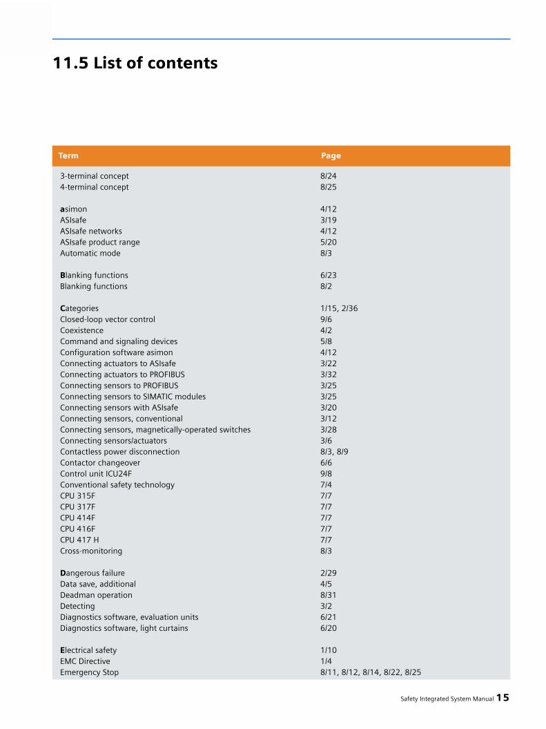
Safety Integrated System Manual 15
Term Page
3-terminal concept 8/244-terminal concept 8/25
asimon 4/12ASIsafe 3/19ASIsafe networks 4/12ASIsafe product range 5/20Automatic mode 8/3
Blanking functions 6/23Blanking functions 8/2
Categories 1/15, 2/36Closed-loop vector control 9/6Coexistence 4/2Command and signaling devices 5/8Configuration software asimon 4/12Connecting actuators to ASIsafe 3/22Connecting actuators to PROFIBUS 3/32Connecting sensors to PROFIBUS 3/25Connecting sensors to SIMATIC modules 3/25Connecting sensors with ASIsafe 3/20Connecting sensors, conventional 3/12Connecting sensors, magnetically-operated switches 3/28Connecting sensors/actuators 3/6Contactless power disconnection 8/3, 8/9Contactor changeover 6/6Control unit ICU24F 9/8Conventional safety technology 7/4CPU 315F 7/7CPU 317F 7/7CPU 414F 7/7CPU 416F 7/7CPU 417 H 7/7Cross-monitoring 8/3
Dangerous failure 2/29Data save, additional 4/5Deadman operation 8/31Detecting 3/2Diagnostics software, evaluation units 6/21Diagnostics software, light curtains 6/20
Electrical safety 1/10EMC Directive 1/4Emergency Stop 8/11, 8/12, 8/14, 8/22, 8/25
11.5 List of contents
16 Safety Integrated System Manual
11 – Appendix
Term Page
Emergency Stop Switch 5/7Emergency Switching-Off 1/9, 1/15EnDat interface 8/5ET 200S Safety Motor Starter Solution Local 5/26ET 200S Safety Motor Starter Solution PROFIsafe 5/30EU Directive 1/4European Machinery Directive 1/3, 1/5, 1/15, 1/20Evaluating 3/2
Frequency control 9/6Function block 2/17Functional safety 1/2
Group Standards 1/9
Hazard 2/5Host-guest combination 6/20
ID for transmitters and receivers 4/5IEC 62061 2/13IM 151-7 CPU 7/7ISO 13849 or IEC 62061 2/15
Lifecycle model 2/2Light curtains 6/16Light grids 6/17Limits of a machine 2/5Linear motors 8/5, 8/6Location field 4/2Low-Voltage Directive 1/15, 1/20
MASTERDRIVES 9/2Metal forming technology 8/32Multi-scan 6/22Muting functions 6/25
Neutral conductor 1/19
One cable solution 4/3
P(lus)/G(round) switching 8/25, 8/26, 8/27, 8/28, 8/29P(lus)/p(lus) switching 8/26, 8/29Position switches 5/2Power module IPM25 9/8Power module PM-D F PROFIsafe 5/30, 9/10Power module PM-D FX1 5/28, 9/11

Safety Integrated System Manual 17
Term Page
prEN ISO 13849-1 2/12Press control unit 5/14Probability of failure 2/29Process automation 7/5Process control technology 1/21Product Standards 1/10Production automation 7/5PROFIBUS connection PROFIsafe 3/24PROFIBUS User Organization 4/3PROFIsafe profile 4/2Proprietary safety PLC 7/4Protective conductor 1/19Protective field calculation 6/9Prototype-tested safety functions 8/3Pulse cancellation 8/11
Regulations 7/6Remaining risk 1/12Responding 3/2Restart inhibit 6/6Risk analysis 2/4Risk assessment 2/6Risk diagram 2/12Risk elements 2/9Risk evaluation 1/10, 2/6Risk evaluation 2/6Risk reduction 1/12, 2/3Risk reduction 1/22, 2/3, 2/6
Safe brake control (SBC) 9/5Safe braking ramp (SBR) 8/12, 9/8Safe operating stop (SBH) 8/12Safe programmable logic (SPL) 8/14Safe software cams (SN) 8/13Safe standstill (SH) 8/10, 9/3, 9/5, 9/8Safely-reduced speed (SG) 8/13, 9/9Safety information 4/4Safety Integrity 2/9Safety Matrix 7/10Safety monitor ASIsafe 4/10Safety Performance 2/9Safety relays 5/11Safety telegrams, consecutive numbering 4/5Safety tolerance signals 4/2Safety-related control system 2/19Safety-related input/output signals (SGE/SGA) 8/15

18 Safety Integrated System Manual
11 – Appendix
Term Page
Safety-related parts of a control 2/34Securing dangerous areas 6/3Setting-up operation 8/3Seveso Directive 1/3, 1/20Shutdown group 9/10SIL monitor 4/6SIMATIC ET 200S 9/6SIMODRIVE 8/8, 9/2SINAMICS S120 9/4SINUMERIK 8/8Software limit switch (SE) 8/13Speed/standstill monitoring 8/2, 8/9, 8/22SRECS 2/19Standard automation 7/3Standards 7/6Start, manual 3/10Start, monitored 3/10Starters 9/4, 9/6Stop categories 1/14Stop responses 8/9, 8/13, 8/22Stopping 1/16, 9/8Subsystem 2/18Subsystem 2/18Synchronous build-in motors 1FE 8/6System design 2/23System integration 2/26System intervention 8/4
Test operation 8/31Test stop 8/12, 8/28Time expected with acknowledgment 4/5Transceiver 6/19
Useful telegrams 4/4
Safety Integrated System Manual 19
Impressum:
Safety Integrated:System Manual Safety Technology, 5th Edition
Published by:Siemens AGAutomation and Drives GroupPostfach 4848, D-90327 Erlangen
Authors responsible for the contents:Georg Becker (A&D PT7)Robert Gassner (A&D CD)Maximilian Korff (A&D CD)Hartmut von Krosigk (A&D ATS)Jürgen Lange (A&D MC)Stefan Lechner (A&D PT7)Peter Maurer (A&D MC)Guillaume Maigret (A&D CD)Bernard Mysliwiec (A&D AS)Uwe Schade (A&D CD)Carsten Schmidt (A&D CD)Jürgen Strässer (A&D MC)Lutz Teschke (I&S IS)Bernhard Wöll (A&D AS)
Concept, Support, Coordination and Editors:Wolfgang Kotitschke (A&D SE)Johanna Gebhardt (A&D CD)Sybill von Hofen (A&D GC)
Layout:NEW ORANGE DESIGN, Obernzenn
Printing:Farbendruck Hofmann, Langenzenn
® 2005 by Siemens AGBerlin and Munich
We reserve all rightsLicense fee 20.- €

Subject to change without prior notice
Siemens Aktiengesellschaft
Automation and DrivesLow Voltage Controls and DistributionP.O. Box 3240, D-91050 Erlangen
Automation and DrivesIndustrial Automation SystemsP.O. Box 4848, D-90327 Nürnberg
Automation and DrivesMotion Control SystemsP.O. Box 3180, D-91050 Erlangen
www.siemens.de/safety
Order No. 6ZB5 000-0AA02-0BA1Printed in GermanyDispostelle 06 345 / SEK 30 296


