Safe Recovery (and repair) of Buses and Coaches fitted with air suspension The Health and Safety Executive (HSE) Written by: Geoff Frackelton of the Health and Safety Executive Crown Copyright 2006
Transcript
Safe Recovery (and repair) of Buses and Coaches fitted with
air suspension
The Health and Safety Executive (HSE)
Written by: Geoff Frackelton of the Health and Safety Executive Crown Copyright 2006
1. WHO SHOULD READ THIS NOTE?............................................................... 1
2. PURPOSE OF THIS GUIDANCE NOTE.......................................................... 1
2.1. This guide excludes:................................................................................... 1
10. FURTHER GUIDANCE.............................................................................. 17
Safe Recovery (and repair) of Buses and Coaches Fitted With Air Suspension
1 of 18
1. WHO SHOULD READ THIS NOTE?
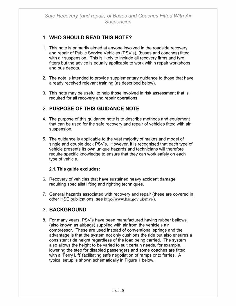
1. This note is primarily aimed at anyone involved in the roadside recovery and repair of Public Service Vehicles (PSV’s), (buses and coaches) fitted with air suspension. This is likely to include all recovery firms and tyre fitters but the advice is equally applicable to work within repair workshops and bus depots.
2. The note is intended to provide supplementary guidance to those that have
already received relevant training (as described below). 3. This note may be useful to help those involved in risk assessment that is
required for all recovery and repair operations.
2. PURPOSE OF THIS GUIDANCE NOTE 4. The purpose of this guidance note is to describe methods and equipment
that can be used for the safe recovery and repair of vehicles fitted with air suspension.
5. The guidance is applicable to the vast majority of makes and model of
single and double deck PSV’s. However, it is recognised that each type of vehicle presents its own unique hazards and technicians will therefore require specific knowledge to ensure that they can work safely on each type of vehicle.
2.1. This guide excludes:
6. Recovery of vehicles that have sustained heavy accident damage
requiring specialist lifting and righting techniques. 7. General hazards associated with recovery and repair (these are covered in
other HSE publications, see http://www.hse.gov.uk/mvr/).
3. BACKGROUND 8. For many years, PSV’s have been manufactured having rubber bellows
(also known as airbags) supplied with air from the vehicle’s air compressor. These are used instead of conventional springs and the advantage is that the system not only cushions the ride but also ensures a consistent ride height regardless of the load being carried. The system also allows the height to be varied to suit certain needs, for example, lowering the step for disabled passengers and some coaches are fitted with a ‘Ferry Lift’ facilitating safe negotiation of ramps onto ferries. A typical setup is shown schematically in Figure 1 below.
Safe Recovery (and repair) of Buses and Coaches Fitted With Air Suspension
2 of 18
Figure 1 - Schematic layout of air suspension components.
9. A characteristic of air suspension is that vehicle ground clearance can
suddenly and unexpectedly change due to a drop in air pressure. This presents crushing and trapping hazards to technicians recovering or repairing vehicles especially if working beneath the vehicle. Figure 2 illustrates just how limited ground clearance is, even on conventional height buses. For modern low floor buses or when suspension deflates clearance can be much less.
Figure 2 - Clearance on conventional bus with inflated suspension.
Air Bellows (also known as air bags)
Levelling Valve
Conventional Damper
Chassis
Axle Levelling Valve Linkage
Safe Recovery (and repair) of Buses and Coaches Fitted With Air Suspension
3 of 18
10. A number of incidents have been reported to HSE where technicians have been seriously injured or killed because air suspension has deflated whilst they were attempting to reach components located beneath the vehicle. In each case the air bellows suddenly and unexpectedly ruptured or deflated leaving a very small clearance between the vehicle structure and the ground.
11. In addition to crush injuries, a bellows has the potential to cause hearing
damage from the bang as it ruptures and there is a risk of fragments being ejected from the bellows at high speed.
12. In recent years the risks have increased because vehicles have been
introduced with extremely low ground clearance (low floor buses). In addition, sophisticated electronics are used to control several interlinked systems that are capable of effecting ground clearance when the technician is least expecting it to do so and without warning. For example, opening the doors, applying the parking brake and even taking the bus out of drive can cause the control system to reduce ground clearance in expectation that the bus has arrived at a bus stop. Even on less complex systems suspension can alter unexpectedly because of air leaks, tampering with the suspension or component failure.
4. TRAINING 13. Technicians should receive relevant training before carrying out recovery
or repair of buses and coaches fitted with air ride suspension. ‘Relevant training’ for technicians means training that is task related, practical and realistic. Technicians should be able to demonstrate their competence and working knowledge before they are allowed to undertake work activities alone and unsupervised. Technicians should understand their duties and responsibilities relating to the recovery of vehicles. They should attend regular refresher and updating courses to ensure they are aware of current legislation, new techniques and advances in equipment. Further details on the minimum content of recovery training is provided in BS 7121 Part 12:1999 Safe use of cranes – Part 12: recovery vehicles and equipment – Code of practice.
5. SAFE RECOVERY METHODS
5.1. Main categories of recovery 14. In many cases the engine will still operate on the casualty vehicle but this
does not necessarily mean that the vehicle is driveable. For example it may have transmission problems, brake seizure, air supply failure/leaks or accident damage. Each casualty vehicle must be considered on a case-by-case basis to decide if it needs recovering or can be repaired at the roadside. The training and experience of the person doing the work will have an important role in the final decision.
Safe Recovery (and repair) of Buses and Coaches Fitted With Air Suspension
4 of 18
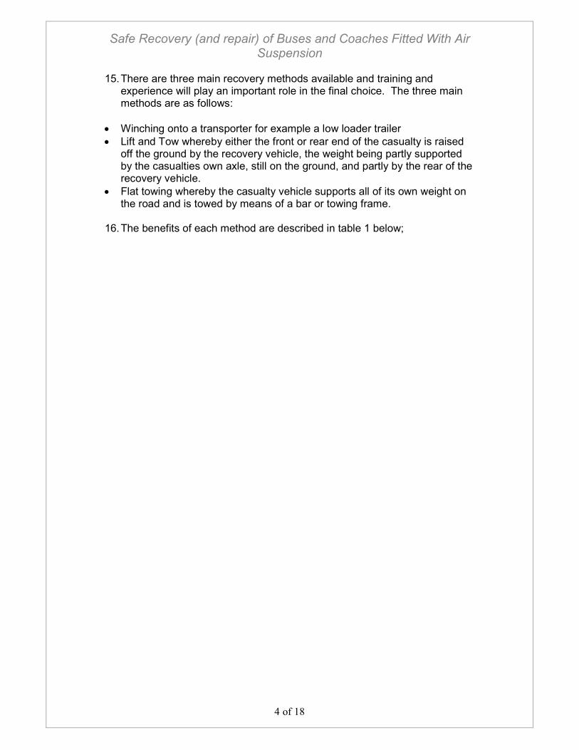
15. There are three main recovery methods available and training and experience will play an important role in the final choice. The three main methods are as follows:
• Winching onto a transporter for example a low loader trailer
• Lift and Tow whereby either the front or rear end of the casualty is raised off the ground by the recovery vehicle, the weight being partly supported by the casualties own axle, still on the ground, and partly by the rear of the recovery vehicle.
• Flat towing whereby the casualty vehicle supports all of its own weight on the road and is towed by means of a bar or towing frame.
16. The benefits of each method are described in table 1 below;
Safe Recovery (and repair) of Buses and Coaches Fitted With Air Suspension
5 of 18
Table 1 – Main recovery methods
Advantages Disadvantages
Fully inflated suspension not necessary
Not normally suitable for double deckers due to height restrictions.
Only requires one man to operate.
Air supply generally needed for brakes
Transmission does not need to be uncoupled
Blocks may be required to increase the ground clearance of the vehicle during loading and unloading.
Transporter
Easier to drive and control after recovery
Fully inflated suspension not always required depending on the route.
Suspension needs to have some height
Only requires one man to operate.
Crush injuries have occurred in the past beneath the lifting arm.
If the brakes cannot be released on one axle it can be lifted using the other axle to tow the vehicle.
The length of the load and the front overhang cause problems when cornering.
Emergency braking can lead to casualty vehicle going out of control.
Air supply needed for brakes
Lift and Tow
Transmission needs to be uncoupled.
Can be towed with deflated suspension on some roads depending on condition, speed humps etc.
Air supply needed for brakes. Flat Tow
Does not require access to underside of vehicle unless brakes cannot be released by air pressure.
Requires two drivers, one in casualty vehicle and one in recovery vehicle.
Good communication and coordination between both drivers is essential.
Transmission needs to be uncoupled.
Towing eyes can fail or can be missing leading to make shift connections
Some functions of the vehicle being towed can be lost if the engine will not run, eg power assisted steering, lighting.
Cornering can be difficult and emergency braking can lead to casualty vehicle going out of control (pendulum effect)
Safe Recovery (and repair) of Buses and Coaches Fitted With Air Suspension
6 of 18
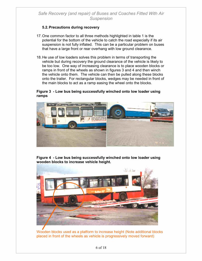
5.2. Precautions during recovery 17. One common factor to all three methods highlighted in table 1 is the
potential for the bottom of the vehicle to catch the road especially if its air suspension is not fully inflated. This can be a particular problem on buses that have a large front or rear overhang with low ground clearance.
18. He use of low loaders solves this problem in terms of transporting the vehicle but during recovery the ground clearance of the vehicle is likely to be too low. One way of increasing clearance is to place wooden blocks or ramps in front of the wheels as shown in figures 3 and 4 and then winch the vehicle onto them. The vehicle can then be pulled along these blocks onto the trailer. For rectangular blocks, wedges may be needed in front of the main blocks to act as a ramp easing the wheel onto the blocks.
Figure 3 - Low bus being successfully winched onto low loader using ramps
Figure 4 - Low bus being successfully winched onto low loader using wooden blocks to increase vehicle height.
Wooden blocks used as a platform to increase height (Note additional blocks placed in front of the wheels as vehicle is progressively moved forward)
Safe Recovery (and repair) of Buses and Coaches Fitted With Air Suspension
Page 7 of 18
19. When winching a casualty vehicle onto a low loader trailer it is essential to always create and maintain a safe working area with special attention to pedestrians and other road users. Nobody should be allowed to stand behind the casualty vehicle during winching. Remote controlled winches make this process much safer because the technician can control the winch from a safe position but with the opportunity to move around to maximise his personal safety and to gain a clear view of the operation. The technician should avoid the need to climb onto the trailer/bus but if absolutely necessary precautions should be in place to avoid falling from height.
20. Caution must be taken when using towing hitches because manufacturers rate hitches to empty curbside weight only. When using screw in tow eyes, particular attention should be paid to threads for damage. Recovery technicians should carry a thread tap so that the threads of the towing eye socket can be cleaned prior to inserting the towing eye. To avoid the threads on towing eyes becoming stripped out under tension it is essential that they screw in to an adequate thread length. To avoid them bending, it may be necessary to fit washers under the head to ensure that the eye seats solidly.
6. SAFE WORKING ON VEHICLES
6.1. Gaining access beneath a vehicle 21. A vehicle can nearly always be recovered without the need to go
underneath. Where it is deemed to be essential to go beneath a vehicle, a higher level of planning and assessment will be necessary but in any case:-
22. PERSONS SHOULD NEVER GO BENEATH A VEHICLE UNLESS THE
VEHICLE IS ADEQUATELY SUPPORTED BY SUITABLY RATED PROPS OR STANDS AND WHEELS ARE CHOCKED.
23. After raising the height using a jack, Props and Stands should be placed
under the vehicle or its wheels. 24. Despite a large number of components being located beneath vehicles it is
often possible to access many from above via access panels in the vehicle floor or through panels in the side of the vehicle. For example the spring brake chambers often have access panels above them as shown in figure 5. Wherever possible these access features should be used in preference to crawling beneath the vehicle. However, the usability of these features suffers with age as panels become seized or covered over. Furthermore, some access panels are large whilst others only provide limited access as shown in figure 6.
Safe Recovery (and repair) of Buses and Coaches Fitted With Air Suspension
Page 8 of 18
Figure 5 – Large access panel to give full access to spring brake chambers.
Figure 6 – Small access panel between seats giving limited access to spring brake chambers.
25. It is foreseeable that there will be certain circumstances where it is unavoidable to gain access to the underside of the vehicle or to reach under, for example, to manually release the brakes, via the spring brake chambers, remove prop shafts and connect auxiliary supplies. When these situations occur it is essential that technicians have the appropriate training, experience and equipment to enable them to undertake the work safely (see previous section of this guidance on Training).
6.2. Air bellows
26. UNDER NO CIRCUMSTANCES SHOULD AIR SUSPENSION BE
TAMPERED WITH IN AN ATTEMPT TO RAISE THE HEIGHT OF THE CASUALTY VEHICLE. (The exception being where a proprietary ferry lift device is
fitted which is designed to raise the vehicle safely). 27. Tampering with the ride height of the vehicle suspension can result in
sudden and unexpected deflation of the air bellows resulting in collapse of the suspension. This causes the vehicle to fall, often instantaneously, with the potential to crush anybody working beneath it.
28. Tampering with ride height can result in the maximum system air pressure
(or higher if a recovery vehicle air supply is used) being supplied to the bellows. The bellows may not be capable of withstanding this increase, especially if it has weakened due to ageing, this can cause it will burst as shown in figure 7. Even a brand new bellows can unseat from its mounts causing instant deflation.
Safe Recovery (and repair) of Buses and Coaches Fitted With Air Suspension
Page 9 of 18
Figure 7 – Typical bellows that has been over inflated
29. Even without tampering with the ride height a bellows can suddenly and
unexpectedly deflate due to a failed pipe or a fall in system air pressure. 30. On modern vehicles there is an added hazard in that there are numerous
functions on the vehicle that are interlocked with the ride height. For example, simply opening the doors or applying the park brake on modern vehicles can cause the ground clearance to suddenly reduce with the potential to crush persons working beneath the vehicle.
6.3. Raising the vehicle safely
31. On the rare occasions where it is deemed necessary to crawl beneath a
vehicle or where a wheel needs changing, proprietary jacks should be used to raise the vehicle before placing stands under the vehicle or its wheels.
32. The design of some modern buses has deviated from the traditional rigid
chassis and separate body attached to it. Instead, the body often incorporates structural members or is supported by a light space frame and in some cases even the glazing is used to increase structural strength. Normally these vehicles have jacking points, as shown in figure 8, designated by the manufacturer. It is essential that recovery technicians know where these are, otherwise the technician could be injured and/or the vehicle could be permanently damaged if the vehicle is jacked at the wrong point.
Safe Recovery (and repair) of Buses and Coaches Fitted With Air Suspension
Page 10 of 18
Figure 8 - Jacking point on a space frame vehicle
Jacking point 33. For the vast majority of vehicles, irrespective of design, solid structural
members such as axles or other suspension components can be used to jack up and support a vehicle safely. As a rule of thumb, a support point will be adequate if the vehicles weight is normally supported at this point when running on its wheels.
6.4. Air Supplies
34. It is common for the system air pressure to be low on casualty vehicles
and for it to be incapable of regenerating its own pressure. Hence, most vehicles are equipped with an auxiliary, air connection point (normally an ‘n’ type coupling or ‘ISO’ type fitting) behind the front panel of the vehicle that can be coupled to the recovery vehicle. Often brake circuits have dual systems and therefore two air supplies may be required to remove the brakes. The air supplies on recovery trucks may be colour coded, for example the ‘yellow’ service line and the ‘red’ emergency line may both be required to release the brakes.
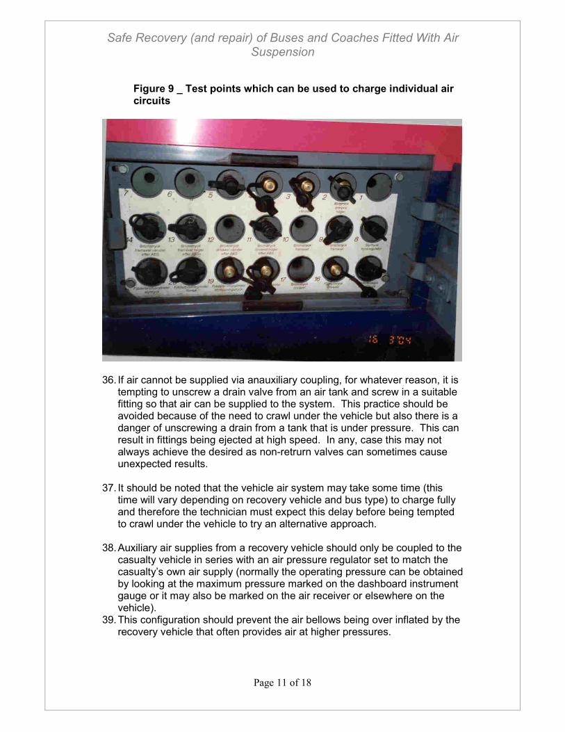
35. On some modern vehicles each individual air circuit can be tapped into.
These systems enable specific functions to be selected as required, for example, park brakes, transmission, doors, etc. Access to these circuits is normally from a convenient panel at the side of the vehicle as shown in figure 9, therby providing a safe method of supplying auxiliary air. However, this system requires the technician to carry the correct fittings on his recovery vehicle.
Safe Recovery (and repair) of Buses and Coaches Fitted With Air Suspension
Page 11 of 18
Figure 9 _ Test points which can be used to charge individual air circuits
36. If air cannot be supplied via anauxiliary coupling, for whatever reason, it is
tempting to unscrew a drain valve from an air tank and screw in a suitable fitting so that air can be supplied to the system. This practice should be avoided because of the need to crawl under the vehicle but also there is a danger of unscrewing a drain from a tank that is under pressure. This can result in fittings being ejected at high speed. In any, case this may not always achieve the desired as non-retrurn valves can sometimes cause unexpected results.
37. It should be noted that the vehicle air system may take some time (this
time will vary depending on recovery vehicle and bus type) to charge fully and therefore the technician must expect this delay before being tempted to crawl under the vehicle to try an alternative approach.
38. Auxiliary air supplies from a recovery vehicle should only be coupled to the
casualty vehicle in series with an air pressure regulator set to match the casualty’s own air supply (normally the operating pressure can be obtained by looking at the maximum pressure marked on the dashboard instrument gauge or it may also be marked on the air receiver or elsewhere on the vehicle).
39. This configuration should prevent the air bellows being over inflated by the recovery vehicle that often provides air at higher pressures.
Safe Recovery (and repair) of Buses and Coaches Fitted With Air Suspension
Page 12 of 18
6.5. Transmission 40. For towing, other than short distances, many vehicles require the
transmission to be disengaged to avoid transmission damage from lack of oil circulation. In addition, it may be necessary to de-activate a microprocessor on computerised gearboxes. Disengaging the transmission by removing drive shafts (known as half shafts) or prop shafts should only be undertaken when traffic conditions allow it to be done safely. Recovering vehicles onto low loader trailers eliminate these hazards because it is unnecessary to disengage the transmission.
41. Often, drive axles have a double reduction hub and wheel bearings that
are fed with oil from the axle. On these types of axle technicians often prefer to crawl beneath the vehicle and remove prop shafts so that they do not cause oil spillage. A safer method is to remove half shafts and then fit plugs into the resulting hole to minimise oil loss. However, the recovery technician will need to have a range of plugs readily available to suit the entire range of casualty vehicles he is likely to recover. In some circumstances this may not be reasonably practicable depending on the range of vehicles likely to be recovered.
6.6. Brakes
42. In some cases brakes can be released by applying air pressure to the
brake chamber either directly or indirectly via other parts of he air circuit. Where air cannot be applied, winding off the brake springs manually will be the only option.
43. Before attempting to release brakes it is clearly important to ensure that
the wheels of the vehicle have been chocked. 44. Even if a brake pipe is broken, a temporary repair can sometimes be
made, eg using air hose and hose clips, to form a continuous pipe again so that system can be temporarily charged to move the vehicle.
45. There are a number of instances where a brake mechanism can seize
locking the brake shoe onto the brake drum. In these scenarios the brake cannot be wound off manually and this may require access beneath the vehicle to dismantle components to free the brake. However,
46. Under no circumstances should technicians attempt to release the spring entirely from its chamber as incidents have been reported where springs have been ejected at very high speed.
7. EQUIPMENT
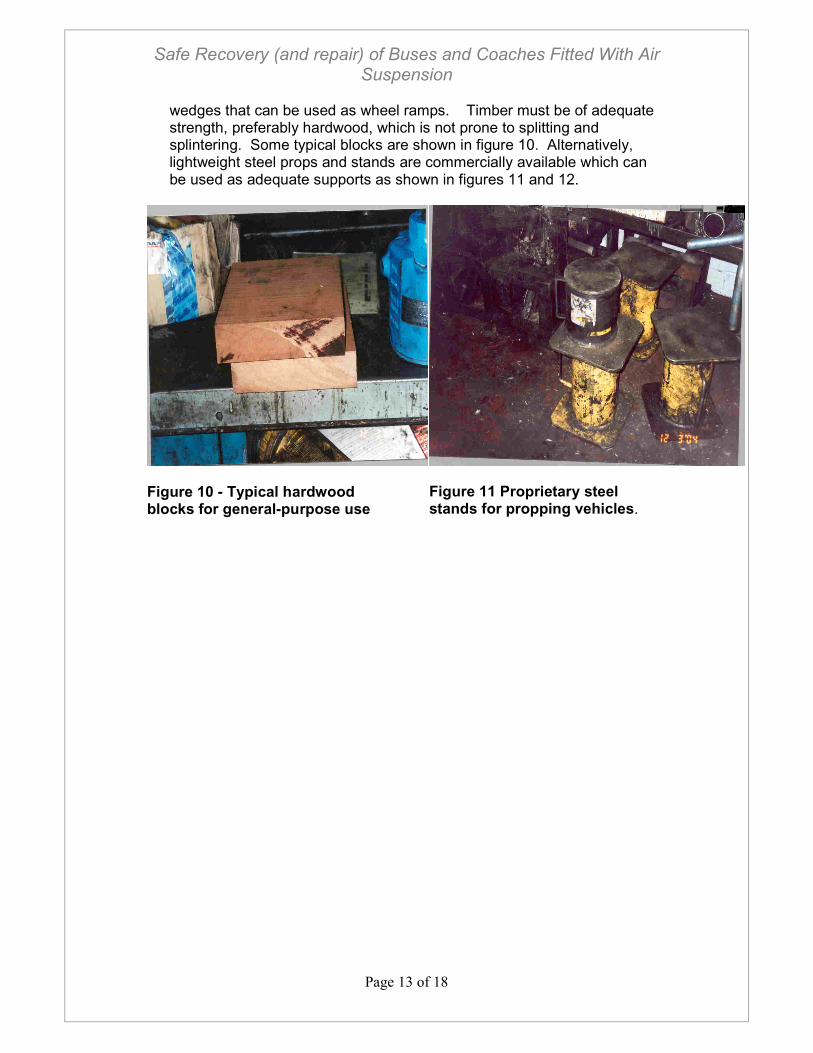
47. Recovery vehicles should always be equipped with a sufficient quantity of good quality timber to support and prop casualty vehicles along with
Safe Recovery (and repair) of Buses and Coaches Fitted With Air Suspension
Page 13 of 18
wedges that can be used as wheel ramps. Timber must be of adequate strength, preferably hardwood, which is not prone to splitting and splintering. Some typical blocks are shown in figure 10. Alternatively, lightweight steel props and stands are commercially available which can be used as adequate supports as shown in figures 11 and 12.
Figure 10 - Typical hardwood blocks for general-purpose use
Figure 11 Proprietary steel stands for propping vehicles.
Safe Recovery (and repair) of Buses and Coaches Fitted With Air Suspension
Page 14 of 18
Figure 12 - Proprietary wheel stands used to support a vehicle once it has been jacked up.
48. Vehicles with extremely low ground clearance may need to be raised first
using proprietary jacks. There are two basic types of jack, either air cushion or hydraulic/pneumatic.
49. Air cushion jacks, as shown in figures 13 and 14 have the advantage that
they deflate to a very low profile, which can easily be positioned under a rigid member beneath the vehicle. An air supply from the recovery vehicle is then used to inflate the cushion.
Figure 13 - Air cushion jack deflated
Figure 14 - Air cushion jack inflated
50. Hydraulic jacks come in many different forms but it is common for low buses to use sets of jacks where a low profile jack initially raises the
Safe Recovery (and repair) of Buses and Coaches Fitted With Air Suspension
Page 15 of 18
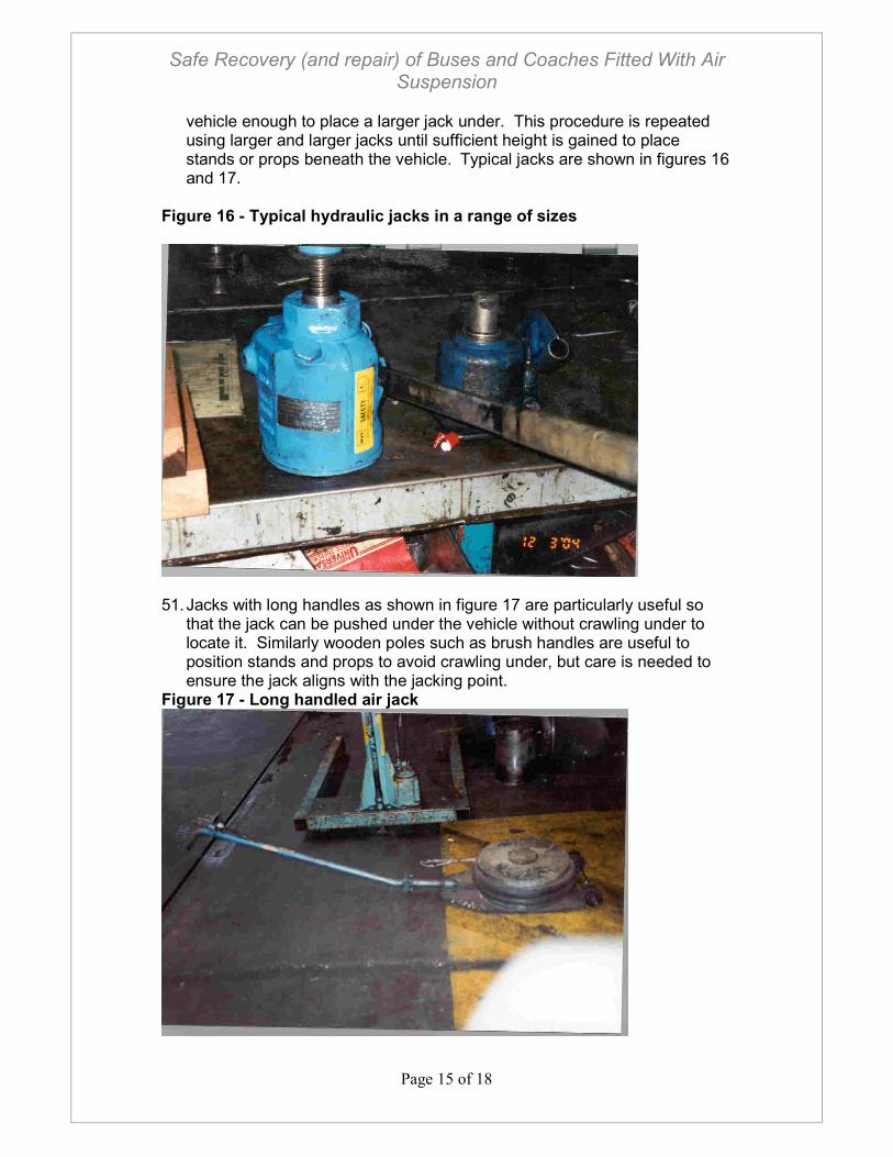
vehicle enough to place a larger jack under. This procedure is repeated using larger and larger jacks until sufficient height is gained to place stands or props beneath the vehicle. Typical jacks are shown in figures 16 and 17.
Figure 16 - Typical hydraulic jacks in a range of sizes
51. Jacks with long handles as shown in figure 17 are particularly useful so
that the jack can be pushed under the vehicle without crawling under to locate it. Similarly wooden poles such as brush handles are useful to position stands and props to avoid crawling under, but care is needed to ensure the jack aligns with the jacking point.
Figure 17 - Long handled air jack
Safe Recovery (and repair) of Buses and Coaches Fitted With Air Suspension
Page 16 of 18
52. The lift on a recovery vehicle offers an alternative to jacking but the vehicle and the lifting beam must be adequately propped so that it cannot fall. This option should only be used as a last resort where jacking is not possible because its safety relies on a very carefully controlled system of work to ensure that the recovery vehicle and its controls are not moved.
8. MAINTENANCE AND INSPECTION OF EQUIPMENT
8.1. All Equipment 53. All tools, machinery, plant and equipment used at work are covered by the
requirements of the Provision and Use of Work Equipment Regulations 1998 (PUWER). Examples of equipment under PUWER include axle stands, props, towing bars, etc.
54. PUWER requires that work equipment, exposed to conditions causing
deterioration liable to result in dangerous situations, be inspected at suitable intervals to ensure that its integrity is maintained and any deterioration detected and remedied in good time. In addition to formal inspection regimes, technician’s who use the equipment should visually examine it on a daily basis, or at least before use, for obvious signs of deterioration. Suspect equipment should be withdrawn from service immediately and either replaced or repaired as appropriate.
55. Written procedures for recovery operations should cover how technicians
are to deal with equipment that they consider to be faulty. This must include instruction to ensure the equipment is not used, how to report the defect and how to get the equipment replaced.
56. Some items of equipment, for example jacks, will require regular
maintenance, in accordance with the manufacturers instructions. Such maintenance should not be overlooked, as it is vital to ensure that equipment remains in a condition that is safe to use.
8.2. Lifting equipment
57. Work equipment that is also lifting equipment will be subject to the
requirements of the Lifting Operations and Lifting Equipment Regulations 1998 (LOLER) as far as the lifting parts are concerned and PUWER for the remainder. LOLER requires lifting equipment to be thoroughly examined by a competent person at periodic intervals to detect any defects. Thorough examination is likely to be required for jacks and other lifting accessories such as slings, chains, eyebolts, shackles, etc. Records from this thorough examination should be kept and made available at all times. .
58. Both LOLER and PUWER have an Approved Code of Practice (ACOP)
accompanying them, referenced below. Further information may also be
Safe Recovery (and repair) of Buses and Coaches Fitted With Air Suspension
Page 17 of 18
found in HSE information document HSE803/69, available on the HSE website.
9. CONCLUSION 59. When repairing or recovering buses and coaches fitted with air
suspension, technicians must take great care to ensure that the vehicle cannot suddenly and unexpectedly fall and trap them. The risk of this happening is significantly reduced if two basic principles are adopted:
NEVER CRAWL BENEATH A VEHICLE FITTED WITH AIR SUSPENSION UNLESS IT IS PROPERLY SUPPORTED. NEVER TAMPER WITH THE RIDE HEIGHT FOR THE PURPOSES OF RECOVERY OR REPAIR.
60. It should be possible to adhere to these two essential principles if the task
is adequately planned and sufficient time is allowed for it. Recovery technicians should not feel Police, other officials or their employer, are rushing them. Sufficient planning means that:
• The risks associated with each task are adequately assessed.
• Each task is fully explained so that it is fully understood by the technician. His roles and responsibilities in the task must also be clearly understood as well as those of his colleagues.
• All technicians have specific knowledge of the casualty vehicle and carry the necessary equipment to undertake the job safely.
• The technician arrives with a suitable recovery vehicle (if recovery is necessary)
• Working procedures are planned and well rehearsed
• Equipment is in a safe condition by virtue of adequate inspection, maintenance and examination and has been subject to statutory examination.
• Technicians understand the procedures about what to do if their training and instructions do not cover the situation encountered.
• Documentation should be in place to ensure that all of the above measures, controls and plans are correctly implemented.
10. FURTHER GUIDANCE 61. Further advice on safe systems of work for ensuring the health and safety
of both roadside technicians and members of the public who may be affected by their activities, may be obtained form the following publications:
• British standard code of practice, BS7121-12:1999 Safe use of cranes – part 12: Recovery vehicles and equipment – code of practice.
Safe Recovery (and repair) of Buses and Coaches Fitted With Air Suspension
Page 18 of 18
• British standards institute (BSI) publication - PAS43 Safe working of vehicle breakdown and recovery operators: Management systems specification.
• BS7901 Specification for recovery vehicles and vehicle recovery equipment specifies the performance requirements for equipment to be used for vehicle recovery activities.
• HSE publication, L22- Safe use of work equipment, Provision and Use of Work Equipment Regulations 1998, Approved Code Of Practice and Guidance, ISBN 0-7176-1626-6.
• HSE publications, L113- Safe use of lifting equipment, Lifting Operations and Lifting Equipment Regulations 1998, Approved Code Of Practice and Guidance, ISBN 0-7176-1628-2.