162
@

@
This book, the second revision and update of IAEA/NVS/1, provides a comprehensive overview of the techniques and equipment underlying the implementation of IAEA safeguards, including those used for nuclear material accountancy, containment and surveillance measures, environ-mental sampling, and data security. It highlights equipment and techniques already in frequent use for inspection purposes as well as those in the late stages of development. A separate sec-tion on new and novel technologies presents some possible verification tools for meeting future safeguards challenges.
INTERNATIONAL ATOMIC ENERGY AGENCYVIENNA
ISBN 978–92–0–118910–3ISSN 1020–6205
Safeg
uards Techniq
ues and E
quip
ment: 2011 E
ditio
n
11-25091_cover.indd 1 2011-12-02 11:10:04

SAFEGUARDS TECHNIQUESAND EQUIPMENT: 2011 EDITION

The following States are Members of the International Atomic Energy Agency:
AFGHANISTANALBANIAALGERIAANGOLAARGENTINAARMENIAAUSTRALIAAUSTRIAAZERBAIJANBAHRAINBANGLADESHBELARUSBELGIUMBELIZEBENINBOLIVIABOSNIA AND HERZEGOVINABOTSWANABRAZILBULGARIABURKINA FASOBURUNDICAMBODIACAMEROONCANADACENTRAL AFRICAN
REPUBLICCHADCHILECHINACOLOMBIACONGOCOSTA RICACÔTE D’IVOIRECROATIACUBACYPRUSCZECH REPUBLICDEMOCRATIC REPUBLIC
OF THE CONGODENMARKDOMINICAN REPUBLICECUADOREGYPTEL SALVADOR
GHANAGREECEGUATEMALAHAITIHOLY SEEHONDURASHUNGARYICELANDINDIAINDONESIAIRAN, ISLAMIC REPUBLIC OF IRAQIRELANDISRAELITALYJAMAICAJAPANJORDANKAZAKHSTANKENYAKOREA, REPUBLIC OFKUWAITKYRGYZSTANLAO PEOPLE’S DEMOCRATIC
REPUBLICLATVIALEBANONLESOTHOLIBERIALIBYALIECHTENSTEINLITHUANIALUXEMBOURGMADAGASCARMALAWIMALAYSIAMALIMALTAMARSHALL ISLANDSMAURITANIAMAURITIUSMEXICOMONACOMONGOLIAMONTENEGRO
NIGERNIGERIANORWAYOMANPAKISTANPALAUPANAMAPARAGUAYPERUPHILIPPINESPOLANDPORTUGALQATARREPUBLIC OF MOLDOVAROMANIARUSSIAN FEDERATIONSAUDI ARABIASENEGALSERBIASEYCHELLESSIERRA LEONESINGAPORESLOVAKIASLOVENIASOUTH AFRICASPAINSRI LANKASUDANSWEDENSWITZERLANDSYRIAN ARAB REPUBLICTAJIKISTANTHAILANDTHE FORMER YUGOSLAV
REPUBLIC OF MACEDONIATUNISIATURKEYUGANDAUKRAINEUNITED ARAB EMIRATESUNITED KINGDOM OF
GREAT BRITAIN AND NORTHERN IRELAND
UNITED REPUBLIC OF TANZANIA
The Agency’s Statute was approved on 23 October 1956 by the Conference on the Statute of thIAEA held at United Nations Headquarters, New York; it entered into force on 29 July 1957. ThHeadquarters of the Agency are situated in Vienna. Its principal objective is “to accelerate and enlarge thcontribution of atomic energy to peace, health and prosperity throughout the world’’.
ERITREAESTONIAETHIOPIAFINLANDFRANCEGABONGEORGIAGERMANY
MOROCCOMOZAMBIQUEMYANMARNAMIBIANEPAL NETHERLANDSNEW ZEALANDNICARAGUA
UNITED STATES OF AMERICAURUGUAYUZBEKISTANVENEZUELAVIETNAMYEMENZAMBIAZIMBABWE
e e e
INTERNATIONAL NUCLEAR VERIFICATIONSERIES No. 1 (Rev. 2)
SAFEGUARDS TECHNIQUESAND EQUIPMENT: 2011 EDITION
INTERNATIONAL ATOMIC ENERGY AGENCYVIENNA, 2011

IAEA Library Cataloguing in Publication Data
Safeguards techniques and equipment. – 2011 edition. – Vienna : International Atomic Energy Agency, 2011.
p. ; 24 cm. – (International nuclear verification series, ISSN 1020-6205 ; no. 1 (Rev. 2))
IAEA/NVS/1/2011 (Rev. 2)ISBN 978-92-0-118910-3Includes bibliographical references.1. Nuclear reactors – Materials – Analysis. 2. Nuclear reactors – Containment. 3. Environmental sampling. I. International Atomic Energy Agency. II. Series.
IAEAL 11-00714
FOREWORD
The 1990s saw significant developments in the global non-proliferation landscape, resulting in a new period of safeguards development. Following an assessment of how to strengthen the effectiveness and improve the efficiency of IAEA safeguards, in May 1997 the IAEA Board of Governors adopted the Model Protocol Additional to the Agreement(s) between State(s) and the International Atomic Energy Agency for the Application of Safeguards (issued as INFCIRC/540 (Corrected)). By significantly broadening the role of IAEA safeguards, the additional protocol heralded a new era for the IAEA safeguards system.
To facilitate the introduction of the strengthened safeguards system, in 1997 the IAEA began to publish a new series of publications on safeguards, called the International Nuclear Verification Series. These books aim to help explain IAEA safeguards, especially in relation to new developments, particularly to facility operators and relevant government officials.
The current publication, which is the second revision and update of IAEA/NVS/1, is intended to give a full and balanced description of the safeguards techniques and equipment used for nuclear material accountancy, containment and surveillance measures, environmental sampling, and data security. New features include a section on new and novel technologies. As new verification measures continue to be developed, the material in this book will be reviewed periodically and updated versions issued.

EDITORIAL NOTE
Although great care has been taken to maintain the accuracy of information contained in this publication, neither the IAEA nor its Member States assume any responsibility for consequences which may arise from its use.
The use of particular designations of countries or territories does not imply any judgement by the publisher, the IAEA, as to the legal status of such countries or territories, of their authorities and institutions or of the delimitation of their boundaries.
The mention of names of specific companies or products (whether or not indicated as registered) does not imply any intention to infringe proprietary rights, nor should it be construed as an endorsement or recommendation on the part of the IAEA.
CONTENTS
1. INTRODUCTION . . . . . . . . . . . . . . . . . . . . . . . . . . . . . . . . . . . . . . . 1
2. NON-DESTRUCTIVE ANALYSIS . . . . . . . . . . . . . . . . . . . . . . . . . . 5
2.1. Gamma ray spectrometry . . . . . . . . . . . . . . . . . . . . . . . . . . . . . . 62.1.1. Gamma emission and detection of nuclear materials . . . 6
2.1.1.1. Multichannel analysers . . . . . . . . . . . . . . . . . . 62.1.1.2. Gamma ray detectors . . . . . . . . . . . . . . . . . . . 7
2.1.2. Low and medium resolution gamma spectrometrytechniques . . . . . . . . . . . . . . . . . . . . . . . . . . . . . . . . . . . . 8
2.1.3. High resolution gamma spectrometry techniques . . . . . 132.2. Neutron counting . . . . . . . . . . . . . . . . . . . . . . . . . . . . . . . . . . . . 15
2.2.1. Neutron emission and detection in non-irradiatedfissile fuel . . . . . . . . . . . . . . . . . . . . . . . . . . . . . . . . . . . . 15
2.2.2. Gross neutron counting . . . . . . . . . . . . . . . . . . . . . . . . . 182.2.3. Neutron coincidence counting . . . . . . . . . . . . . . . . . . . . 19
2.2.3.1. Passive detector systems . . . . . . . . . . . . . . . . . 202.2.3.2. Active detector systems . . . . . . . . . . . . . . . . . 23
2.2.4. Multiplicity coincidence counting . . . . . . . . . . . . . . . . . 242.3. Spent fuel measurement . . . . . . . . . . . . . . . . . . . . . . . . . . . . . . . 26
2.3.1. Neutron and gamma emission and detection . . . . . . . . . 262.3.2. Gross neutron and gamma ray detection . . . . . . . . . . . . 262.3.3. Gamma ray energy spectral analysis . . . . . . . . . . . . . . . 302.3.4. Gamma ray intensity scanning . . . . . . . . . . . . . . . . . . . . 322.3.5. Neutron coincidence methods . . . . . . . . . . . . . . . . . . . . 342.3.6. Cerenkov radiation detection . . . . . . . . . . . . . . . . . . . . . 34
2.4. Other NDA techniques . . . . . . . . . . . . . . . . . . . . . . . . . . . . . . . . 362.4.1. Radiation measurement . . . . . . . . . . . . . . . . . . . . . . . . . 372.4.2. Physical property measurement . . . . . . . . . . . . . . . . . . . 38
3. UNATTENDED MONITORING . . . . . . . . . . . . . . . . . . . . . . . . . . . . 42
3.1. MGBS family . . . . . . . . . . . . . . . . . . . . . . . . . . . . . . . . . . . . . . . 46
3.2. SRBS family . . . . . . . . . . . . . . . . . . . . . . . . . . . . . . . . . . . . . . . 483.3. VIFM family . . . . . . . . . . . . . . . . . . . . . . . . . . . . . . . . . . . . . . . 493.4. SEGM family . . . . . . . . . . . . . . . . . . . . . . . . . . . . . . . . . . . . . . . 503.5. MUND family . . . . . . . . . . . . . . . . . . . . . . . . . . . . . . . . . . . . . . 50
3.6. ATPM family . . . . . . . . . . . . . . . . . . . . . . . . . . . . . . . . . . . . . . . 523.7. Other instruments . . . . . . . . . . . . . . . . . . . . . . . . . . . . . . . . . . . . 52
4. CONTAINMENT AND SURVEILLANCE . . . . . . . . . . . . . . . . . . . . 55
4.1. Surveillance . . . . . . . . . . . . . . . . . . . . . . . . . . . . . . . . . . . . . . . . 564.1.1. Single camera system for easy to access locations . . . . 614.1.2. Single camera system for difficult to access locations . . . 624.1.3. Multiple camera system . . . . . . . . . . . . . . . . . . . . . . . . . 634.1.4. Short term surveillance . . . . . . . . . . . . . . . . . . . . . . . . . 644.1.5. Underwater television for attended applications . . . . . . 644.1.6. Next generation of surveillance system (NGSS) . . . . . . 674.1.7. High intensity LED light . . . . . . . . . . . . . . . . . . . . . . . . 694.1.8. Surveillance review software . . . . . . . . . . . . . . . . . . . . . 69
4.2. Containment (seals) . . . . . . . . . . . . . . . . . . . . . . . . . . . . . . . . . . 694.2.1. Single use seals . . . . . . . . . . . . . . . . . . . . . . . . . . . . . . . 704.2.2. In situ verifiable seals . . . . . . . . . . . . . . . . . . . . . . . . . . 73
4.3. Containment verification . . . . . . . . . . . . . . . . . . . . . . . . . . . . . . 76
5. REMOTE MONITORING SYSTEMS . . . . . . . . . . . . . . . . . . . . . . . . 78
5.1. Remote monitoring equipment . . . . . . . . . . . . . . . . . . . . . . . . . 795.2. Remote monitoring data centre . . . . . . . . . . . . . . . . . . . . . . . . . 805.3. Data sharing . . . . . . . . . . . . . . . . . . . . . . . . . . . . . . . . . . . . . . . . 805.4. Future development activities . . . . . . . . . . . . . . . . . . . . . . . . . . 81
5.4.1. Communication methods . . . . . . . . . . . . . . . . . . . . . . . . 825.4.2. Facility integration . . . . . . . . . . . . . . . . . . . . . . . . . . . . . 83
6. DESTRUCTIVE ANALYSIS . . . . . . . . . . . . . . . . . . . . . . . . . . . . . . . 85
6.1. Elemental analysis . . . . . . . . . . . . . . . . . . . . . . . . . . . . . . . . . . . 886.1.1. Uranium analysis by potentiometric titration . . . . . . . . . 886.1.2. Plutonium analysis by controlled potential
coulometry . . . . . . . . . . . . . . . . . . . . . . . . . . . . . . . . . . . 886.1.3. Uranium or plutonium analysis by isotope dilution
mass spectrometry . . . . . . . . . . . . . . . . . . . . . . . . . . . . . 88
6.1.4. Uranium analysis by ignition gravimetry . . . . . . . . . . . . 906.1.5. Uranium, thorium and plutonium analysis by K-edgedensitometry . . . . . . . . . . . . . . . . . . . . . . . . . . . . . . . . . . 916.1.6. Plutonium analysis by K X ray fluorescence analysis . . . 91
6.2. Isotopic analysis . . . . . . . . . . . . . . . . . . . . . . . . . . . . . . . . . . . . . 926.2.1. Uranium or plutonium isotopic composition measurement
by thermal ionization mass spectrometry . . . . . . . . . . . . 926.2.2. Plutonium isotopic composition measurement by high
resolution gamma ray spectrometry . . . . . . . . . . . . . . . . 936.2.3. Alpha spectrometry . . . . . . . . . . . . . . . . . . . . . . . . . . . . 94
6.3. Other destructive analysis techniques . . . . . . . . . . . . . . . . . . . . 946.3.1. Inductively coupled plasma mass spectrometry . . . . . . . 946.3.2. Spectrophotometric determination of hexavalent
plutonium . . . . . . . . . . . . . . . . . . . . . . . . . . . . . . . . . . . . 946.3.3. Assay of transuranic elements other than plutonium . . . 95
7. ENVIRONMENTAL SAMPLING . . . . . . . . . . . . . . . . . . . . . . . . . . . 97
7.1. IAEA environmental sample laboratory . . . . . . . . . . . . . . . . . . 977.2. Screening of samples . . . . . . . . . . . . . . . . . . . . . . . . . . . . . . . . . 100
7.2.1. Low level gamma ray spectrometry . . . . . . . . . . . . . . . . 1007.2.2. X ray fluorescence spectrometry . . . . . . . . . . . . . . . . . . 1007.2.3. Alpha/beta counting . . . . . . . . . . . . . . . . . . . . . . . . . . . . 102
7.3. Bulk analysis . . . . . . . . . . . . . . . . . . . . . . . . . . . . . . . . . . . . . . . 1027.4. Particle analysis . . . . . . . . . . . . . . . . . . . . . . . . . . . . . . . . . . . . . 103
7.4.1. Fission track method . . . . . . . . . . . . . . . . . . . . . . . . . . . 1037.4.2. Pulse counting thermal ionization mass spectrometry . . 1047.4.3. Secondary ion mass spectrometry . . . . . . . . . . . . . . . . . 106
8. NEW AND NOVEL TECHNOLOGIES . . . . . . . . . . . . . . . . . . . . . . 109
8.1. New technologies . . . . . . . . . . . . . . . . . . . . . . . . . . . . . . . . . . . . 1098.2. Novel technologies . . . . . . . . . . . . . . . . . . . . . . . . . . . . . . . . . . . 114
9. DATA SECURITY . . . . . . . . . . . . . . . . . . . . . . . . . . . . . . . . . . . . . . . 123
9.1. Requirements . . . . . . . . . . . . . . . . . . . . . . . . . . . . . . . . . . . . . . . 1239.1.1. Authentication (integrity, authenticity) . . . . . . . . . . . . . 1239.1.2. Confidentiality . . . . . . . . . . . . . . . . . . . . . . . . . . . . . . . . 1269.1.3. Non-repudiation . . . . . . . . . . . . . . . . . . . . . . . . . . . . . . . 126
9.1.4. Time stamping . . . . . . . . . . . . . . . . . . . . . . . . . . . . . . . . 1269.1.5. Access control . . . . . . . . . . . . . . . . . . . . . . . . . . . . . . . . 1279.2. Implementation . . . . . . . . . . . . . . . . . . . . . . . . . . . . . . . . . . . . . 1279.2.1. Verification data . . . . . . . . . . . . . . . . . . . . . . . . . . . . . . . 1289.2.2. Technical data . . . . . . . . . . . . . . . . . . . . . . . . . . . . . . . . . 128

9.2.3. Control data . . . . . . . . . . . . . . . . . . . . . . . . . . . . . . . . . . 1309.2.4. Virtual private networks . . . . . . . . . . . . . . . . . . . . . . . . . 1319.2.5. Safeguards mailbox . . . . . . . . . . . . . . . . . . . . . . . . . . . . 131
9.3. State requirements . . . . . . . . . . . . . . . . . . . . . . . . . . . . . . . . . . . 132
LIST OF ACRONYMS AND ABBREVIATIONS . . . . . . . . . . . . . . . . . . . 135
1. INTRODUCTION
The IAEA has the task of providing continuing assurance to the international community that States that have entered into safeguards agreements with the IAEA are meeting their obligations. This requires assurance that any diversion of safeguarded nuclear material to a proscribed military purpose would be detected and that all nuclear material in a State with a safeguards agreement has been declared. To this end, the IAEA must be able to verify the correctness and completeness of the reports that it receives from States concerning the nuclear material subject to safeguards.
In addition, the IAEA has the right and obligation to verify States’ compliance with commitments under their safeguards agreements and, where applicable, additional protocols. In particular, as part of the implementation of the additional protocol and integrated safeguards, inspectors must be able to confirm the absence of undeclared nuclear materials and activities during inspections and complementary access.
The basic verification measure used by the IAEA is nuclear material accountancy. In applying nuclear material accountancy, IAEA safeguards inspectors perform independent measurements to verify quantitatively the amount of nuclear material presented in the State’s accounts. For this purpose, inspectors count items (e.g. fuel assemblies, bundles or rods, or containers of powdered compounds of uranium or plutonium), measure attributes of these items during their inspections using non-destructive analysis (NDA) techniques, and compare their findings with the declared figures and the operator’s records. The purpose of this activity is to detect missing items (gross defects). The next level of verification aims to detect whether a fraction of a declared amount is missing (partial defect) and may involve the weighing of items and measurements using NDA techniques such as neutron counting or γ ray spectrometry. These techniques are capable of measuring an amount of nuclear material with an accuracy of the order of a few per cent. For detecting bias defects, which would arise if small amounts of material were diverted over a protracted length of time, it is necessary to sample some of the items and to apply physical and chemical analysis techniques of the highest possible accuracy, typically less than 1%. In order to apply these destructive analysis techniques, the IAEA requires access to
1
laboratories that employ such accurate techniques on a routine basis.Containment and surveillance (C/S) techniques, which are complementary
to nuclear material accountancy techniques, are applied in order to maintain continuity of the knowledge gained through IAEA verification, by giving assurance that nuclear material follows predetermined routes, that the integrity of its containment remains unimpaired and that the material is accounted for at the

SAFEGUARDS TECHNIQUES AND EQUIPMENT
correct measurement points. They also lead to savings in the safeguards inspection effort (e.g. by reducing the required frequency of accountancy verification). A variety of C/S techniques are applied, primarily optical surveillance and sealing. These measures serve as a backup to nuclear material accountancy through monitoring access to nuclear material and detecting any undeclared movement of material.
Unattended and remote monitoring is a special mode of application of NDA or C/S techniques, or a combination of these techniques, that operates for extended periods without the presence of inspectors. In remote monitoring, the unattended equipment transmits the data off-site. For unattended and remote monitoring, additional criteria must be met, including high reliability and authentication of the data source. Expanded deployment of unattended and remote monitoring systems has become an increasingly important element of IAEA efforts to maintain and increase safeguards effectiveness while reducing overall costs.
Data security is an important feature of unattended and remote monitoringsystems. In fact, these types of safeguards system installed for extended periods at facilities and periodically visited by inspectors transmit data between the components of different systems and between systems and IAEA Headquarters over unsecured transmission paths. These data need to be verified to guarantee their authenticity and may need to be encrypted to avoid disclosure of specific information and/or to provide assurance of confidentiality to States.
Environmental sampling, which allows the detection of minute traces of nuclear material, was added to the IAEA’s verification measures in the mid-1990s as a powerful tool for detecting indications of undeclared nuclear activities. The non-detection of even minute traces of a specific nuclear material can provide assurance that no activities utilizing the material took place in the area where the environmental samples were taken.
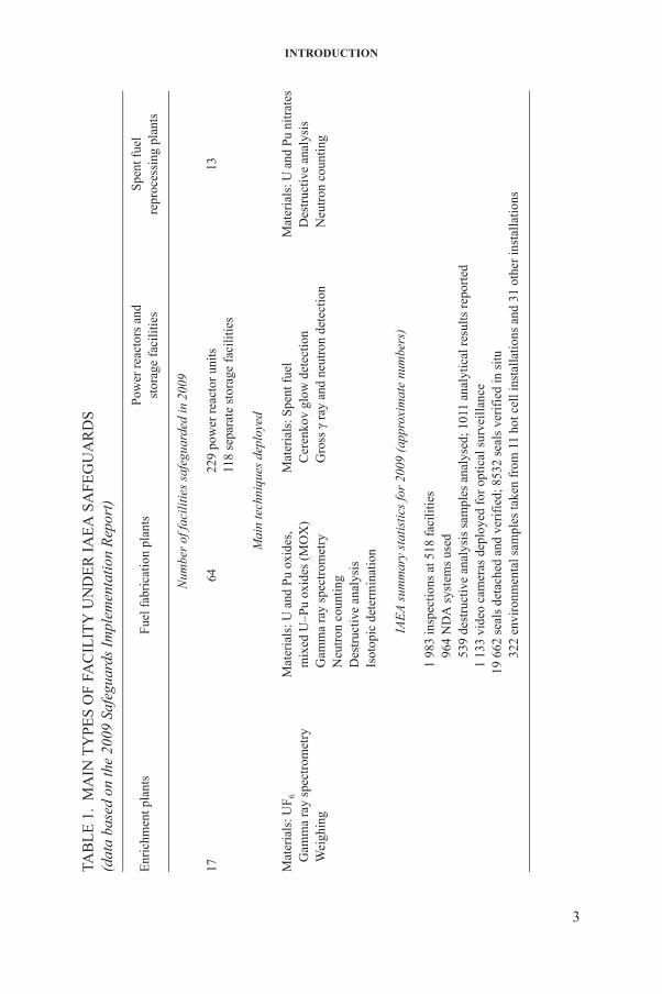
The complexity and diversity of facilities containing safeguarded nuclear material require a correspondingly diverse set of verification techniques and equipment. Table 1 lists the main types of facility where inspections are performed and the primary verification techniques that are implemented at these facilities.
Development of equipment and techniques for safeguards is continuing with the help of Member State support programmes (MSSPs) that assist the IAEA
2
in keeping pace with the evolution of new technology. The IAEA defines the safeguards needs, coordinates the support programmes, and tests and evaluates the techniques and the resulting equipment developed. All aspects of equipment performance are evaluated, including compliance with specifications, reliability and transportability, and, most importantly, suitability for use by IAEA inspectors
INTRODUCTION
TY
PE
S O
F F
AC
ILIT
Y U
ND
ER
IA
EA
SA
FE
GU
AR
DS
e 20
09 S
afeg
uard
s Im
plem
enta
tion
Rep
ort)
Fue
l fab
rica
tion
pla
nts
Pow
er r
eact
ors
and
stor
age
faci
litie
sS
pent
fue
lre
proc
essi
ng p
lant
s
Num
ber
of fa
cili
ties
saf
egua
rded
in 2
009
6422
9 po
wer
rea
ctor
uni
ts11
8 se
para
te s
tora
ge f
acili
ties
13
Mai
n te
chni
ques
dep
loye
d
omet
ryM
ater
ials
: U a
nd P
u ox
ides
,
mix
ed U
–Pu
oxid
es (
MO
X)
G
amm
a ra
y sp
ectr
omet
ry
Neu
tron
cou
ntin
g
Des
truc
tive
anal
ysis
Isot
opic
det
erm
inat
ion
Mat
eria
ls: S
pent
fue
l
Cer
enko
v gl
ow d
etec
tion
G
ross
γ r
ay a
nd n
eutr
on d
etec
tion
Mat
eria
ls: U
and
Pu
nitr
ates
D
estr
ucti
ve a
naly
sis
N
eutr
on c
ount
ing
IAE
A s
umm
ary
stat
isti
cs fo
r 20
09 (
appr
oxim
ate
num
bers
)
1
983
insp
ecti
ons
at 5
18 f
acil
itie
s
96
4 N
DA
sys
tem
s us
ed
539
dest
ruct
ive
anal
ysis
sam
ples
ana
lyse
d; 1
011
anal
ytic
al r
esul
ts r
epor
ted
1
133
vide
o ca
mer
as d
eplo
yed
for
opti
cal s
urve
illa
nce
19
662
seal
s de
tach
ed a
nd v
erif
ied;
853
2 se
als
veri
fied
in s
itu
32
2 en
viro
nmen
tal s
ampl
es ta
ken
from
11
hot c
ell i
nsta
llat
ions
and
31
othe
r in
stal
lati
ons
3
TAB
LE
1.
MA
IN(d
ata
base
d on
th
Enr
ichm
ent p
lant
s
17 Mat
eria
ls: U
F6
G
amm
a ra
y sp
ectr
W
eigh
ing

SAFEGUARDS TECHNIQUES AND EQUIPMENT
in nuclear facilities. The IAEA has an established quality assurance procedure to authorize equipment and software for routine inspection use.
The equipment and techniques highlighted in this publication are those in frequent use for inspection purposes or in the late stages of development. A separate section on new and novel technologies presents some possible verification tools for meeting future safeguards challenges. The overall objective of this publication is to provide a comprehensive overview of the techniques and equipment underlying the implementation of IAEA safeguards.
4
2. NON-DESTRUCTIVE ANALYSIS
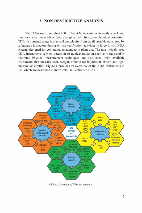
The IAEA uses more than 100 different NDA systems to verify, check and monitor nuclear materials without changing their physical or chemical properties. NDA instruments range in size and complexity from small portable units used by safeguards inspectors during on-site verification activities to large in situ NDA systems designed for continuous unattended in-plant use. The most widely used NDA instruments rely on detection of nuclear radiation such as γ rays and/or neutrons. Physical measurement techniques are also used, with available instruments that measure heat, weight, volume (of liquids), thickness and light emission/absorption. Figure 1 provides an overview of the NDA instruments in use, which are described in more detail in Sections 2.1–2.4.
�-medium resolution SFAT, IRAT
HSGM
Unattended monitoring systems
EnrichmentCHEM
Gammasystems
Low resolutionHM-5IMCN
Mediumresolution
FMATIMCC High
resolutionIMCG, ECGSISOCS, KEDG
� detectorsIC, Si, NaI, CdZnTe,
HpGe
NDA methods
and instruments
Optical L3RF
Other ULTG GPRT CALO
Unattended monitoring systems
Weight LCBSNeutron
detectorsFC
3He ,10BNeutron systems
ActivecoincidenceUNCL, AWCC
PassivecoincidenceHLNC, INVS
UWCC, WCAS
CerenkovICVDDCVD
Passivecoincidence
AEFC
Intensityscanning
CBVBCRPS
Unattended monitoring systems
Neutron/��FDET
SMPY, NGAT
Spent fuel measurement
systemsVolumePPMD
Other physical methods
X ray XRFA HKED CMPU
5
Unattended monitoring systems
MultiplicityPSMC
Gross countingHHNMPNUH
FIG. 1. Overview of NDA instruments.
SAFEGUARDS TECHNIQUES AND EQUIPMENT
2.1. GAMMA RAY SPECTROMETRY
2.1.1. Gamma emission and detection of nuclear materials
Most nuclear materials under IAEA safeguards emit γ rays that can be used for NDA of the materials. Gamma rays have well defined energies that are characteristic of the isotopes emitting them. Determination of the γ ray energies and their relative intensities serves to identify the isotopic composition of the materials. When combined with a measurement of absolute intensities, the γ ray energies can provide quantitative information on the amount of material that is present:
(a) Enriched uranium fuel, for example, has a strong 186 keV γ ray associated with the α decay of 235U, and the 235U enrichment can be verified by measuring this γ ray.
(b) Plutonium samples generally contain the isotopes 238Pu, 239Pu, 240Pu and 241Pu as well as decay products, which give rise to a highly complex mix of characteristic γ ray energies. Plutonium spectra can be analysed to determine the isotopic composition.
(c) The date of irradiated fuel discharge from a reactor can be verified by measuring the relative intensities of γ rays associated with fission and activation products. The 662 keV γ ray from 137Cs is particularly important for this type of determination.
To detect γ rays, the radiation must interact with a detector to give up all or part of the photon energy. The basis of all spectroscopic γ ray detector systems is the collection of this liberated electrical charge to produce a voltage pulse whose amplitude is proportional to the energy deposited by a γ ray in a detector. These pulses are then sorted according to amplitude (energy) and counted using appropriate electronics, such as a single or multichannel analyser. With a multichannel analyser, the γ rays of different energies can be displayed or plotted to produce a γ ray energy spectrum that provides detailed information on the measured material.
2.1.1.1. Multichannel analysers
6
IMCA (InSpector 2000). The InSpector 2000 multichannel analyser (IMCA) is based on digital signal processing (DSP) technology. It can be combined with the various types of detector that are now used for inspection purposes — namely, high purity germanium (HPGe), cadmium zinc telluride (CdZnTe) and sodium iodide (NaI) detectors — allowing high, medium and low
NON-DESTRUCTIVE ANALYSIS
resolution spectrometry. The device provides unsurpassed count rate and resolution performance coupled with environmental stability in a very small and compact package. Its high performance is derived from the application of DSP technology, which digitizes preamplifier signals at the very beginning of the signal processing chain. The use of analog circuitry in the instrument is reduced, resulting in a compact instrument that has increased stability, accuracy and data reproducibility while improving the overall signal acquisition performance. The IMCA has been authorized for inspection use since 2001.
MMCA. The miniature multichannel analyser (MMCA) is a miniaturized spectrometry system that supports all detectors used by the IAEA, including NaI, CdZnTe and HPGe detectors. A battery permits portable use of the MMCA for up to 12 hours when paired with either a CdZnTe or a NaI detector. The MMCA has the footprint of a palmtop computer and weighs 680 g, including the lithium ion battery. Combined with a palmtop computer and a CdZnTe detector, it makes a powerful and versatile system that can easily fit into a briefcase, making it very convenient for many inspection activities.
2.1.1.2. Gamma ray detectors
The γ ray detectors commonly used are either scintillators (usually activated NaI crystals), solid state semiconductors (usually HPGe or CdZnTe crystals) or gas filled detectors (e.g. Geiger–Müller tubes, xenon detectors):
— The NaI detectors can be made with large volumes and generally have higher γ ray detection efficiencies than do germanium detectors. Their safeguards applications include the verification of both 235U enrichment in fresh fuel and the presence of spent fuel through detection of fission product γ radiation. Their ability to distinguish between γ rays of different energies, however, is relatively poor, and of the detector types mentioned here they have the worst energy resolution.
— Germanium detectors have energy resolution far superior to that of NaI detectors and are better suited to the task of resolving complex γ ray spectra and providing information about the isotopic content of materials. The germanium detectors used by the IAEA range in size from small planar types to large (80–90 cm3) coaxial detectors. A disadvantage of these
7
detectors is that they must be operated at a very low temperature, which is usually achieved by cooling with liquid nitrogen. Recently, electric cooling systems have become available, mitigating this disadvantage with almost no effect on detector performance characteristics.
— Standard CdZnTe detectors (and cadmium telluride (CdTe) detectors) do not need cooling, and of the three detector types currently in widespread use
SAFEGUARDS TECHNIQUES AND EQUIPMENT
they have the highest intrinsic detection efficiency. Recent progress in fabrication techniques has substantially improved CdZnTe resolution. Detectors with volumes ranging from 5 to 1500 mm3 are available. The portability and small size of CdZnTe and CdTe detectors have made them especially suitable for use in a wide range of applications, including in confined spaces such as for in situ verification of fresh fuel assemblies whose design permits insertion of only a small detector probe into the assembly interior, and of spent fuel bundles stored underwater in closely packed stacks.
— Recently, new detector materials have been commercialized (e.g. lanthanum bromide (LaBr3)) having a resolution similar to that of CdZnTe and a detection efficiency comparable with that of NaI, which will enhance the detection and identification capabilities for γ rays.
— Gas filled detectors record ionization of the gas in a chamber caused by γ interaction. Gas detectors feature long term stability that cannot be matched by scintillator or solid state detectors because the charge transport properties of gas are not significantly affected by changes in temperature and the effects of radiation. This high stability is very important for detectors in unattended monitoring applications where background temperature and radiation vary significantly. High pressure xenon ionization chambers have recently emerged as low resolution γ ray spectrometers.
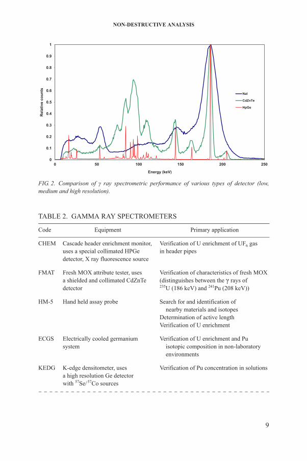
Figure 2 illustrates the capabilities of various types of detector with low, medium and high resolution. Several γ ray spectrometers (multichannel analysersand detectors) that differ mainly in their resolution and analytical capability are being used for safeguards purposes. These spectrometers are summarized in Table 2 and described below.
2.1.2. Low and medium resolution gamma spectrometry techniques
Low and medium resolution γ spectrometry applications in safeguards range from quantitative verification of enrichment levels to the purely qualitative detection of plutonium and uranium in fresh and spent fuel, and of the presence of nuclear material in general. A variety of instruments for spent fuel verification
8
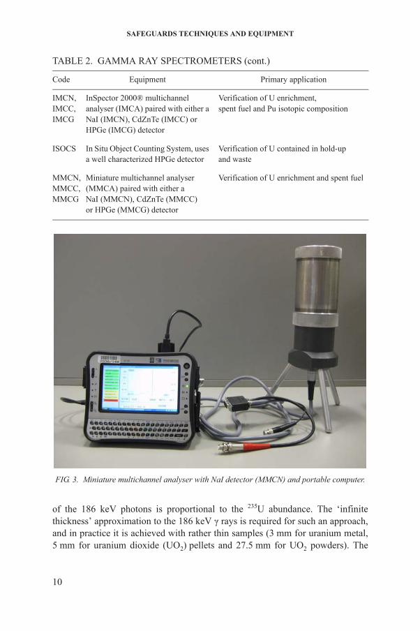
are described in Section 2.3 on spent fuel measurements. MMCN. The MMCA paired with a NaI detector (MMCN) (Fig. 3) is often
used to verify the enrichment of uranium in pure, homogeneous powders and pellets. The enrichment is derived from the intensity of γ rays attributed to 235U (e.g. γ ray at 186 keV). Under a well defined geometry, the measured count rate
NON-DESTRUCTIVE ANALYSIS
TABLE 2. GAMMA RAY SPECTROMETERS
Code Equipment Primary application
CHEM Cascade header enrichment monitor,uses a special collimated HPGedetector, X ray fluorescence source
Verification of U enrichment of UF6 gasin header pipes
FMAT Fresh MOX attribute tester, usesa shielded and collimated CdZnTedetector
Verification of characteristics of fresh MOX(distinguishes between the γ rays of235U (186 keV) and 241Pu (208 keV))
HM-5 Hand held assay probe Search for and identification of nearby materials and isotopesDetermination of active lengthVerification of U enrichment
ECGS Electrically cooled germaniumsystem
Verification of U enrichment and Pu isotopic composition in non-laboratory
0
0.1
0.2
0.3
0.4
0.5
0.6
0.7
0.8
0.9
1
0 50 100 150 200 250
Rel
ativ
e co
unts
Energy (keV)
NaI
CdZnTe
HpGe
FIG. 2. Comparison of γ ray spectrometric performance of various types of detector (low, medium and high resolution).
9
environments
KEDG K-edge densitometer, usesa high resolution Ge detectorwith 57Se/57Co sources
Verification of Pu concentration in solutions
SAFEGUARDS TECHNIQUES AND EQUIPMENT
IMCN,IMCC,IMCG
InSpector 2000® multichannelanalyser (IMCA) paired with either aNaI (IMCN), CdZnTe (IMCC) orHPGe (IMCG) detector
Verification of U enrichment,spent fuel and Pu isotopic composition
ISOCS In Situ Object Counting System, usesa well characterized HPGe detector
Verification of U contained in hold-upand waste
MMCN,MMCC,MMCG
Miniature multichannel analyser(MMCA) paired with either aNaI (MMCN), CdZnTe (MMCC)or HPGe (MMCG) detector
Verification of U enrichment and spent fuel
TABLE 2. GAMMA RAY SPECTROMETERS (cont.)
Code Equipment Primary application
FIG. 3. Miniature multichannel analyser with NaI detector (MMCN) and portable computer.
10
of the 186 keV photons is proportional to the 235U abundance. The ‘infinitethickness’ approximation to the 186 keV γ rays is required for such an approach, and in practice it is achieved with rather thin samples (3 mm for uranium metal, 5 mm for uranium dioxide (UO2) pellets and 27.5 mm for UO2 powders). The
NON-DESTRUCTIVE ANALYSIS
standardized procedure controls the geometry and utilizes specially designed support stands with collimators to provide a quantitative assessment of enrichment within minutes.
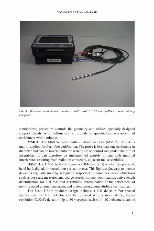
MMCC. The MMCA paired with a CdZnTe detector (MMCC) (Fig. 4) is mainly applied for fresh fuel verification. The probe is less than one centimetre in diameter and can be inserted into the water tube or control rod guide tube of fuel assemblies. It can therefore be implemented entirely in situ with minimal interference resulting from radiation emitted by adjacent fuel assemblies.
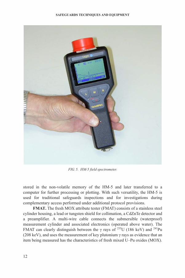
HM-5. The HM-5 field spectrometer (HM-5) (Fig. 5) is a battery powered, hand-held, digital, low resolution γ spectrometer. This lightweight, easy to operate device is regularly used by safeguards inspectors. It combines various functions
FIG. 4. Miniature multichannel analyser with CdZnTe detector (MMCC) and palmtop computer.
11
such as dose rate measurement, source search, isotope identification, active length determination for fuel rods and assemblies, determination of the enrichment of non-irradiated uranium materials, and plutonium/uranium attribute verification.
The basic HM-5 modular design includes a NaI detector. For special applications the NaI detector can be replaced with a more stable, higher resolution CdZnTe detector. Up to 50 γ spectra, each with 1024 channels, can be
SAFEGUARDS TECHNIQUES AND EQUIPMENT
stored in the non-volatile memory of the HM-5 and later transferred to a computer for further processing or plotting. With such versatility, the HM-5 is used for traditional safeguards inspections and for investigations during complementary access performed under additional protocol provisions.
FMAT. The fresh MOX attribute tester (FMAT) consists of a stainless steel
FIG. 5. HM-5 field spectrometer.
12
cylinder housing, a lead or tungsten shield for collimation, a CdZnTe detector and a preamplifier. A multi-wire cable connects the submersible (waterproof) measurement cylinder and associated electronics (operated above water). The FMAT can clearly distinguish between the γ rays of 235U (186 keV) and 241Pu (208 keV), and uses the measurement of key plutonium γ rays as evidence that an item being measured has the characteristics of fresh mixed U–Pu oxides (MOX).
NON-DESTRUCTIVE ANALYSIS
Measurement with FMAT requires movement of the fresh MOX fuel, as the detector approaches the item from the side.
2.1.3. High resolution gamma spectrometry techniques
When coupled to a germanium detector, the MMCA or IMCA becomes a high resolution γ ray spectrometer. This type of spectrometer is often used to determine the 235U enrichment of uranium hexafluoride (UF6) in shipping cylinders. When selecting the UF6 measurement procedure from the options menu in the applications firmware, an inspector is led through a series of predetermined steps to measure and calculate the enrichment. The cylinder wall thickness must also be determined so that corrections for γ ray attenuation in the container wall can be made. The thickness is measured with an ultrasonic thickness gauge.
Inspectors can also use software to expedite the measurement and analysis of high resolution uranium spectra. The Multi-Group Analysis for Uranium(MGAU) software can provide results with an accuracy of 1–2%, provided that the wall thickness of the steel container is less than 10 mm and that the activity of the thorium daughter is in equilibrium with the parent 235U and 238U activities. The MGAU analysis procedure eliminates the need to measure the container wall thickness or to provide an enrichment calibration for the measurement system. Another important application of high resolution γ spectrometry is determination of the isotopic composition of plutonium. Plutonium emits a complex spectrum of X and γ rays, which are interpreted using dedicated software such as the Multi-Group Analysis (MGA) software for plutonium analysis and Fixed-Energy, Response Function Analysis with Multiple Efficiency (FRAM). These codes take advantage of the high energy resolution of the spectra, using a HPGe detector to separate and evaluate the contributions of the different plutonium isotopes. Isotopic determination of plutonium is used to verify the nature of the material and as an input parameter for interpretation of the neutron measurements. The recently developed TARGA software in combination with the IMCA system provides a user friendly environment with the MGA code to determine the isotopic composition of plutonium samples.
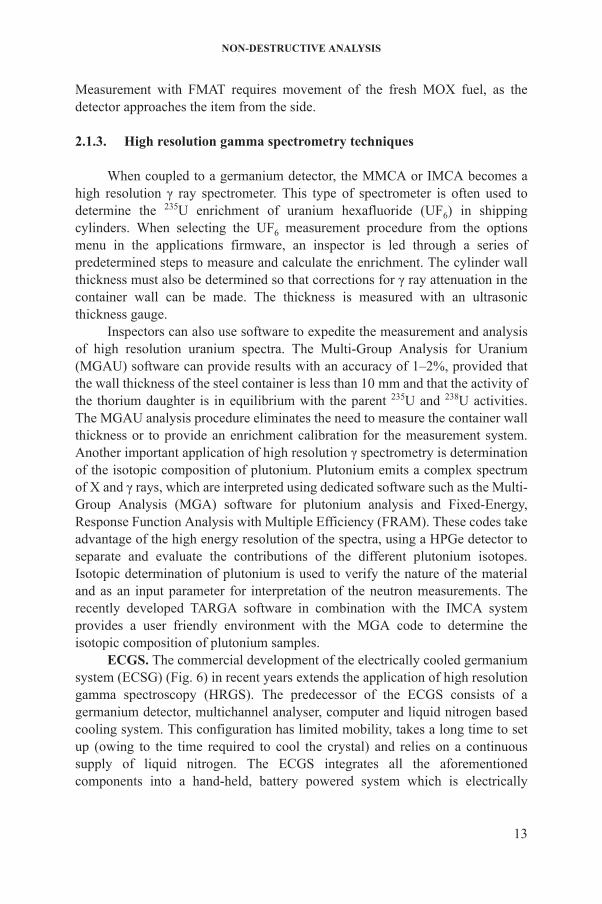
ECGS. The commercial development of the electrically cooled germanium system (ECSG) (Fig. 6) in recent years extends the application of high resolution
13
gamma spectroscopy (HRGS). The predecessor of the ECGS consists of a germanium detector, multichannel analyser, computer and liquid nitrogen based cooling system. This configuration has limited mobility, takes a long time to set up (owing to the time required to cool the crystal) and relies on a continuous supply of liquid nitrogen. The ECGS integrates all the aforementioned components into a hand-held, battery powered system which is electrically
SAFEGUARDS TECHNIQUES AND EQUIPMENT
cooled (and thus does not require liquid nitrogen). Existing HRGS systems — such as those used for UF6 cylinder assay, cascade header pipe uranium enrichment assay and complimentary access kits — will be upgraded with this new technology.
ISOCS. The In Situ Object Counting System (ISOCS) is an intrinsically, numerically calibrated γ spectrometry system incorporating a well characterized HPGe detector. The software is commercially available and is used to verify nuclear materials, in particular uranium, contained in hold-up and waste. The efficiency versus energy function is calculated based on user defined models which take into account all physical parameters describing geometry and sample matrix.
CHEM. The cascade header enrichment monitor (CHEM) uses a HPGe
FIG. 6. Electrically cooled germanium system (ECGS).
14
detector and an X ray fluorescence (XRF) source to measure the enrichment of UF6 gas in a pipe. This system is used to qualitatively confirm the absence of high enriched uranium (HEU) in cascade header pipes of centrifuge enrichment plants. The technique uses an external radiation source (57Co) and a special collimated high resolution γ spectrometry system with specific software to control, perform and evaluate measurements. The XRF measurement provides the amount of total
NON-DESTRUCTIVE ANALYSIS
uranium in the UF6 gas. The presence of deposit on the inside surface of a header pipe requires two measurements of the 235U γ ray at 186 keV under different geometries to determine the amount of 235U in the gas alone. The level of enrichment of uranium in the gas of the header pipe can then be determined independently of the deposit on the inside of the pipe.
KEDG. The K-edge densitometer (KEDG) is facility owned equipment used by the IAEA to determine the plutonium concentration in solutions. The system consists of a high resolution germanium detector, a multichannel analyser and a portable computer. It measures photon transmission through a liquid sample at two energies which bracket (as closely as possible) the K absorption edge energy of the element of interest. The K absorption edge energy represents an element specific signature. A 57Se/57Co source of low energy γ rays is positioned to permit the γ radiation to pass through a small sample vial of the solution. The amount of absorption of this radiation provides a highly sensitive measure of the concentration of plutonium in the sample.
The majority of the KEDGs used for safeguards are now equipped with an X ray generator which acts as a photon source for the transmission measurement. The high photon strength provided by an X ray tube allows measurements to be performed on highly radioactive samples. The method is very selective and is one of the most accurate NDA techniques, but the determination of plutonium may be biased by the presence of a minor actinide element of lower atomic number, such as uranium. This equipment is therefore best used for relatively concentrated solutions (>50 g/L) of plutonium in product solutions, input solutions and process solutions (in-line measurements).
2.2. NEUTRON COUNTING
The IAEA uses several different types of neutron counting equipment (Table 3). This section gives information on the source of the neutrons and on the importance of neutron coincidence counting to obtain the mass of fissile material in the measured sample, as well as a few examples of passive and active detector systems.
2.2.1. Neutron emission and detection in non-irradiated fissile fuel
15
Neutrons are emitted from non-irradiated nuclear fuel primarily in three ways:
(1) Spontaneous fission of uranium and plutonium, mainly in the even isotopes of plutonium;
SAFEGUARDS TECHNIQUES AND EQUIPMENT
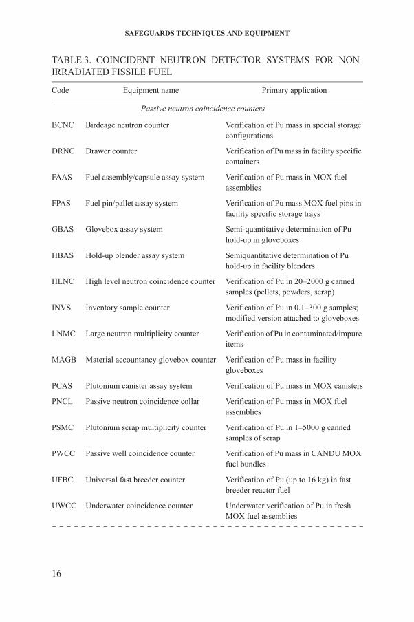
TABLE 3. COINCIDENT NEUTRON DETECTOR SYSTEMS FOR NON-IRRADIATED FISSILE FUEL
Code Equipment name Primary application
Passive neutron coincidence counters
BCNC Birdcage neutron counter Verification of Pu mass in special storage configurations
DRNC Drawer counter Verification of Pu mass in facility specific containers
FAAS Fuel assembly/capsule assay system Verification of Pu mass in MOX fuel assemblies
FPAS Fuel pin/pallet assay system Verification of Pu mass MOX fuel pins in facility specific storage trays
GBAS Glovebox assay system Semi-quantitative determination of Pu hold-up in gloveboxes
HBAS Hold-up blender assay system Semiquantitative determination of Pu hold-up in facility blenders
HLNC High level neutron coincidence counter Verification of Pu in 20–2000 g canned samples (pellets, powders, scrap)
INVS Inventory sample counter Verification of Pu in 0.1–300 g samples; modified version attached to gloveboxes
LNMC Large neutron multiplicity counter Verification of Pu in contaminated/impure items
MAGB Material accountancy glovebox counter Verification of Pu mass in facility gloveboxes
PCAS Plutonium canister assay system Verification of Pu mass in MOX canisters
PNCL Passive neutron coincidence collar Verification of Pu mass in MOX fuel assemblies
PSMC Plutonium scrap multiplicity counter Verification of Pu in 1–5000 g canned samples of scrap
PWCC Passive well coincidence counter Verification of Pu mass in CANDU MOX fuel bundles
16
UFBC Universal fast breeder counter Verification of Pu (up to 16 kg) in fast breeder reactor fuel
UWCC Underwater coincidence counter Underwater verification of Pu in fresh MOX fuel assemblies
NON-DESTRUCTIVE ANALYSIS
(2) Induced fission from fissile isotopes of uranium and plutonium by neutrons from other sources (including external sources);
(3) Alpha particle induced reactions (α,n) involving light elements such as oxygen and fluorine.
Fission neutrons in the first two categories are emitted in numbers ranging from 0 to 10 per fission event. The goal of neutron coincidence counting is to distinguish the neutrons emitted from a single fission event from neutrons created from other processes, including other secondary fission events detected with a uniform time distribution. Nearly all the isotopes of uranium, plutonium and other transuranic elements emit α particles. These interact with light elements present in compounds (e.g. oxides and fluorides) or as impurities (e.g. boron, beryllium and lithium) to form an undesirable neutron background; neutron coincidence counting discriminates against this (α,n) background. This is done by keeping track of the time of neutron detection. Neutrons from the same fission event are detected relatively close to each other in time, whereas neutrons from non-fission processes are randomly distributed in time.
Passive coincidence detector systems determine the mass of plutonium based on spontaneous fission, primarily in the even numbered isotopes (238Pu, 240 242 240
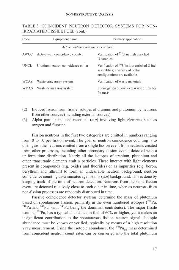
Active neutron coincidence counters
AWCC Active well coincidence counter Verification of 235U in high enrichedU samples
UNCL Uranium neutron coincidence collar Verification of 235U in low enriched U fuel assemblies; a variety of collar configurations are available
WCAS Waste crate assay system Verification of waste materials
WDAS Waste drum assay system Interrogation of low level waste drums for Pu mass
TABLE 3. COINCIDENT NEUTRON DETECTOR SYSTEMS FOR NON-IRRADIATED FISSILE FUEL (cont.)
Code Equipment name Primary application
17
Pu and Pu, with Pu being the dominant contributor). The major fissile isotope, 239Pu, has a typical abundance in fuel of 60% or higher, yet it makes an insignificant contribution to the spontaneous fission neutron signal. Isotopic abundance must be known or verified, typically by means of a high resolution γ ray measurement. Using the isotopic abundance, the 240Pueff mass determined from coincident neutron count rates can be converted into the total plutonium

SAFEGUARDS TECHNIQUES AND EQUIPMENT
mass of the sample. For uncontaminated, well characterized samples, measurement accuracy can be of the order of 1% or less.
The fissile isotope 235U does not undergo sufficient spontaneous fission for practical passive detection. In this case, an active system incorporating americium–lithium (AmLi) neutron sources is used to ‘interrogate’ (induce fission in) the 235U content through neutron induced fission. For low energy incident neutrons, induced fission in the 238U of a sample contributes insignificantly to the measured coincident neutron count rate, even though 235U may be enriched to only a few per cent (e.g. low enrichment fuels).
In general, neutron detectors employ various neutron capture reactions to generate pulses. Helium-3 gas detectors are the most commonly used neutron detectors in safeguards. The detection principle is based on the 3He(n,p)3H reaction. This reaction produces a proton and a triton which share the recoil energy of 764 keV that ionizes the surrounding gas and generates an electronic signal. The neutron absorption cross-section decreases with orders of magnitude as the neutron energy increases, hence moderation of neutrons is essential to achieving a reasonable detection efficiency of the counting system. This is typically achieved by embedding the detectors in hydrogenous materials such as polyethylene. The less commonly used boron trifluoride (BF3) detectors are based on the 10B(n,α)7Li reaction. Boron trifluoride detectors are less sensitive to γ radiation fields but are intrinsically less efficient. Recently, solid state neutron radiation devices with boron carbide (B4C) diodes have been developed which demonstrate very promising potential for future applications such as miniaturized hand-held neutron detection devices.
Fission chambers have a thin layer of 235U plated on the inner wall of a gas filled chamber. Neutrons will cause fission of 235U, producing high energy fission fragments (~90 MeV/fragment). The fission fragments cause ionization in the stopping gas, which is then transformed into an electronic signal. Because of the large quantity of energy deposited by the fission fragments, fission chambers have the highest insensitivity to γ rays (roughly 104 Gy/h) of any of the available neutron detectors. They are the only neutron detectors capable of measuring highly active spent fuel.
2.2.2. Gross neutron counting
18
Gross neutron counting refers to the sum of all neutrons detected. Here the neutron source cannot be characterized, since coincidence techniques are not applied. The presence of significant numbers of neutrons is often a sufficient indication that fissile nuclear material is present. All the neutron coincidence detection systems discussed below determine total neutron count rates as well as coincidence count rates.
NON-DESTRUCTIVE ANALYSIS
HHNM. The hand-held neutron monitor (HHNM) is a portable (~4 kg) neutron detection device with three 3He proportional neutron counters, a Geiger–Müller counter and integrated electronics that provide a means of searching for and localizing neutron radiation sources. A measurement sequence consists of background and verification measurements. When a predetermined threshold is exceeded, the detector triggers an alarm and records the relevant information.
PNUH. The portable neutron uranium hold-up (PNUH) monitor system is a neutron counting system with 3He neutron proportional tubes used to evaluate the quantity of uranium hold-up within the cascade halls of an enrichment plant. PNUH measures the total neutron signals at various prescribed locations and evaluates the measurement data with specialized software.
Other detector systems such as the fork detector and the unattended fuel flow monitor employ gross neutron counting as their primary signature. These systems mainly measure spent fuel materials, as described in Section 2.3 of this book.
2.2.3. Neutron coincidence counting
Neutron coincidence counting has evolved into a very stable, reliable and accurate technique for determining plutonium and 235U content. Modern, well designed neutron coincidence systems are capable of reliably processing pulses over a very large range of input count rates (i.e. over more than six orders of magnitude). Stability is achieved by judicious selection and placement of amplifier electronics to minimize noise interference. The electronics boards, when located at the detector head, amplify and shape the pulses, apply lower level discrimination to remove γ pulses or noise, and feed out very narrow (50 ns wide) logic pulses to an external pulse processor (the electronics controller).
Distinction between time correlated fission neutrons and random neutron events becomes possible owing to a sophisticated pulse processing circuit (shift register electronics) in the external electronics controller. Pulses occurring within a specified time period of one another may be termed correlated (i.e. ‘coincident’) neutron pulses. The correlation time is associated with the slowing down of neutrons in the moderator of the detector head and is typically about 60 µs. The shift register electronics circuitry keeps track of coincidences between pulses
19
separated by about 1000 µs (called ‘accidentals’) and coincidences in the first 64 µs (called ‘real coincidences plus accidentals’). Analysis software subtracts the accidentals data from the ‘real coincidences plus accidentals’ data to determine real coincidences. In analysing the information, various small corrections are also automatically applied.
SAFEGUARDS TECHNIQUES AND EQUIPMENT
2.2.3.1. Passive detector systems
Passive detector systems have two basic geometrical configurations: well detectors, which completely enclose the sample, and collar detectors, which encircle the sample (e.g. a fuel assembly). Well detectors have the preferred geometry since all the neutrons emanating from the sample enter the detector’s sensitive volume. Collar detectors are an alternative design that is appropriate when the sample is too large for placement inside a well detector. Whereas calibrated passive well detectors measure the total mass of plutonium in a sample, collar detectors measure plutonium mass per unit length of a fuel assembly. The linear density must be multiplied by an active length to determine the total plutonium mass in the assembly.
About twenty versions of passive detector systems are currently in use for nuclear safeguards, with design features optimized for specific sample sizes, shapes or plutonium mass ranges. The passive detector systems are listed in Table 3, along with their primary applications. Four representative systems are described below.
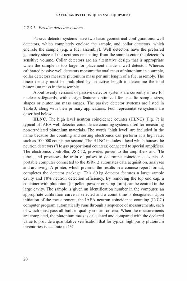
HLNC. The high level neutron coincidence counter (HLNC) (Fig. 7) is typical of IAEA well detector coincidence counting systems used for measuring non-irradiated plutonium materials. The words ‘high level’ are included in the name because the counting and sorting electronics can perform at a high rate, such as 100 000 counts per second. The HLNC includes a head which houses the neutron detectors (3He gas proportional counters) connected to special amplifiers. The electronics controller, JSR-12, provides power to the amplifiers and 3He tubes, and processes the train of pulses to determine coincidence events. A portable computer connected to the JSR-12 automates data acquisition, analyses and archiving. A printer, which presents the results in a concise report format, completes the detector package. This 60 kg detector features a large sample cavity and 18% neutron detection efficiency. By removing the top end cap, a container with plutonium (in pellet, powder or scrap form) can be centred in the large cavity. The sample is given an identification number in the computer, an appropriate calibration curve is selected and a count time is designated. Upon initiation of the measurement, the IAEA neutron coincidence counting (INCC) computer program automatically runs through a sequence of measurements, each of which must pass all built-in quality control criteria. When the measurements
20
are completed, the plutonium mass is calculated and compared with the declared value to provide a quantitative verification that for typical high purity plutonium inventories is accurate to 1%.
NON-DESTRUCTIVE ANALYSIS
FIG. 7. High level neutron coincidence counter (HLNC).
21
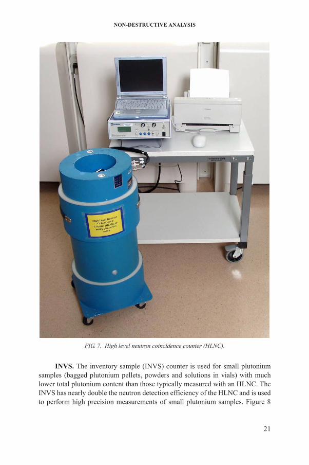
INVS. The inventory sample (INVS) counter is used for small plutonium samples (bagged plutonium pellets, powders and solutions in vials) with much lower total plutonium content than those typically measured with an HLNC. The INVS has nearly double the neutron detection efficiency of the HLNC and is used to perform high precision measurements of small plutonium samples. Figure 8
SAFEGUARDS TECHNIQUES AND EQUIPMENT
shows one of four versions of this portable detector system. In another version, the INVS has an inverted geometry and is permanently attached to the floor of a glovebox so that samples can be assayed for plutonium content without removing them from the glovebox. Although the cavity of an INVS is typically only about 6 cm in diameter and 16 cm high, it is well suited for samples available at facilities such as fuel fabrication plants or on-site laboratories. The INVS provides highly reliable plutonium content verification with an accuracy of up to 1% in individual measurements. Measurement procedures are automated with the INCC program and are essentially the same as for the HLNC.
UWCC. The underwater coincidence counter (UWCC) is a transportable system for measuring fresh MOX fuel stored under water. It is a modified version of the fork detector irradiated fuel measuring system (FDET), where the ionization and fission chambers have been replaced with sensitive 3He tubes embedded in a high density polyethylene measurement head. The UWCC measures neutrons coming from a segment of the MOX fuel in ‘multiplication corrected’ coincidence mode and provides the total mass of plutonium once the isotopics and the active fuel length are known.
WCAS. The waste crate assay system (WCAS) measures the plutonium
FIG. 8. Inventory sample (INVS) counter.
22
content of large waste containers for high and low activity waste (from a few milligrams to tens of kilograms). WCAS is a passive neutron coincidence counter operating in 4π geometry and can work in high radiation fields of up to ~1 Gy/h. The amount of plutonium and 235U in the waste is calculated from the Cm:Pu and Cm:235U ratios, known from the stream average ratios at the waste generating sites. WCAS has a small 252Cf source of known source strength that can be
NON-DESTRUCTIVE ANALYSIS
positioned in an automated sequence at a fixed number of locations adjacent to the waste container wall. A measurement is taken with and without the interrogation source to determine a matrix correction factor for a given configuration.
2.2.3.2. Active detector systems
Active detector systems use neutron sources (typically AmLi) to interrogate the 235U in a sample. A well geometry is again preferred, but a collar geometry is needed when the sample is a fuel assembly. The active neutron detectors in use by IAEA safeguards are listed in Table 3. Details of an active well detector and an active collar detector are presented below. The full detector system includes: a detector head, which detects the neutrons and houses a neutron interrogation source; an electronics controller, which powers the detector and determines the neutron coincidence rates; a portable computer for controlling the measurements and for analysing data to determine 235U content; and a printer for generating reports.
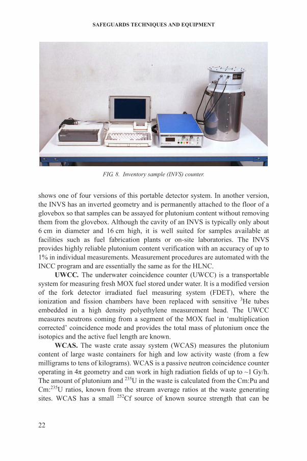
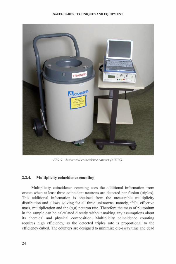
AWCC. The active well coincidence counter (AWCC) (Fig. 9) has a large (150 kg) detector head permanently attached to a wheeled cart for transportability. The AWCC has 42 3He counters embedded in polyethylene, resulting in a relatively high (nearly 30%) neutron detection efficiency. The 235U in a sample is interrogated with two AmLi neutron sources placed in the top and bottom end caps to provide a more uniform distribution of interrogation neutrons over the sample volume. The 20 cm diameter sample cavity size can be adjusted from about 23 to 35 cm in height by removing inserts and reflectors, accommodating samples such as metal discs, canned oxide powders and fuel pebbles in carousels. The INCC program is used to automate the measurement procedure and data analysis to enable high accuracy assays of the 235U content.
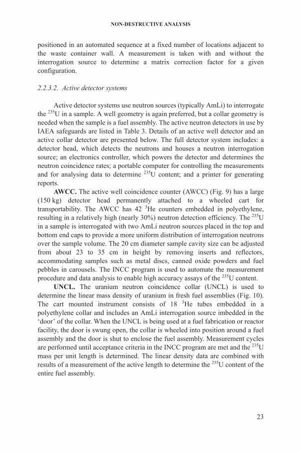
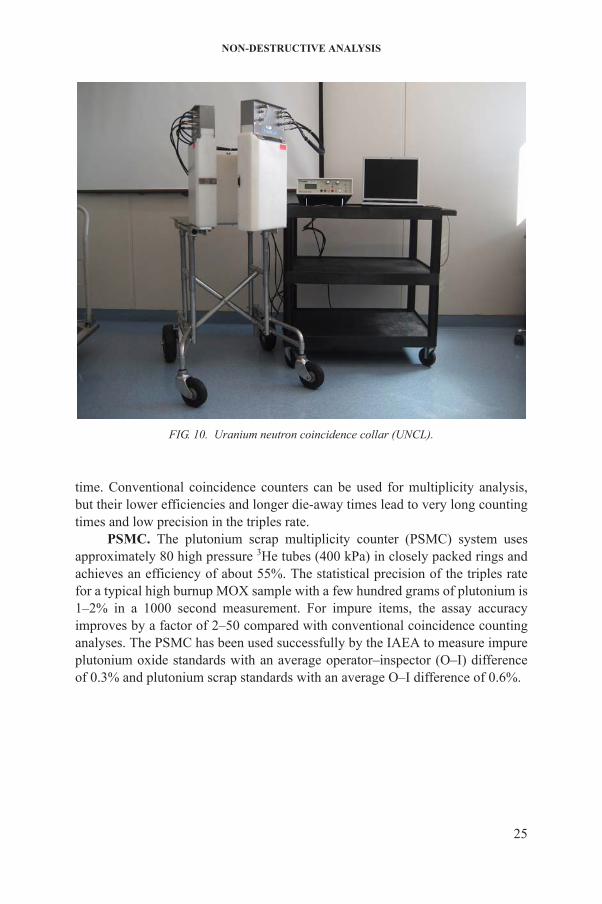
UNCL. The uranium neutron coincidence collar (UNCL) is used to determine the linear mass density of uranium in fresh fuel assemblies (Fig. 10). The cart mounted instrument consists of 18 3He tubes embedded in a polyethylene collar and includes an AmLi interrogation source imbedded in the ‘door’ of the collar. When the UNCL is being used at a fuel fabrication or reactor facility, the door is swung open, the collar is wheeled into position around a fuel assembly and the door is shut to enclose the fuel assembly. Measurement cycles
235
23
are performed until acceptance criteria in the INCC program are met and the U mass per unit length is determined. The linear density data are combined with results of a measurement of the active length to determine the 235U content of the entire fuel assembly.
SAFEGUARDS TECHNIQUES AND EQUIPMENT
2.2.4. Multiplicity coincidence counting
Multiplicity coincidence counting uses the additional information from events when at least three coincident neutrons are detected per fission (triples). This additional information is obtained from the measurable multiplicity
240
FIG. 9. Active well coincidence counter (AWCC).
24
distribution and allows solving for all three unknowns, namely, Pu effective mass, multiplication and the (α,n) neutron rate. Therefore the mass of plutonium in the sample can be calculated directly without making any assumptions about its chemical and physical composition. Multiplicity coincidence counting requires high efficiency, as the detected triples rate is proportional to the efficiency cubed. The counters are designed to minimize die-away time and dead
NON-DESTRUCTIVE ANALYSIS
time. Conventional coincidence counters can be used for multiplicity analysis, but their lower efficiencies and longer die-away times lead to very long counting times and low precision in the triples rate.
PSMC. The plutonium scrap multiplicity counter (PSMC) system uses approximately 80 high pressure 3He tubes (400 kPa) in closely packed rings and achieves an efficiency of about 55%. The statistical precision of the triples rate for a typical high burnup MOX sample with a few hundred grams of plutonium is 1–2% in a 1000 second measurement. For impure items, the assay accuracy improves by a factor of 2–50 compared with conventional coincidence counting analyses. The PSMC has been used successfully by the IAEA to measure impure plutonium oxide standards with an average operator–inspector (O–I) difference of 0.3% and plutonium scrap standards with an average O–I difference of 0.6%.
FIG. 10. Uranium neutron coincidence collar (UNCL).
25
SAFEGUARDS TECHNIQUES AND EQUIPMENT
2.3. SPENT FUEL MEASUREMENT
2.3.1. Neutron and gamma emission and detection
Spontaneous fission in the 242Cm and 244Cm isotopes is the major source of neutrons emanating from spent fuel. These isotopes are produced through multiple neutron capture events when a fuel assembly is exposed to high neutron fluxes in a nuclear reactor. Fission products in the irradiated fuel produce an extremely high radiation background in which the neutrons must be detected. The high radiation environment influences the types of technique that can be deployed for spent fuel verification. One approach is to choose a detector which is basically insensitive to γ rays. Another approach is to shield against the γ rays while allowing neutrons to pass through the shield into the neutron detector. Spent fuel verification methods include not only neutron detection but also γ ray and ultraviolet light (Cerenkov radiation) detection.
The 662 keV γ ray line from 137Cs generally dominates a spectrum for spent fuel that has cooled longer than two years and provides a useful signature for verifying the spent fuel. For shorter cooling times, the 757/766 keV line from 95Nb/95Zr is used to verify the presence of spent fuel.
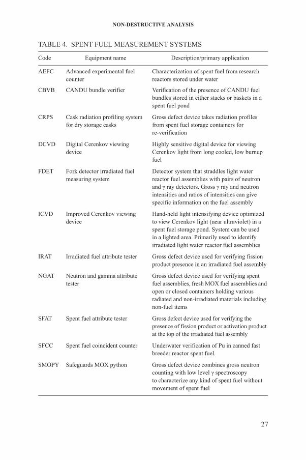
Table 4 lists the spent fuel measurement systems in use by the IAEA. The FDET incorporates both neutron and γ ray detectors for gross defect verification of fuel assembly characteristics such as irradiation history, initial fuel content and number of reactor cycles of exposure. Detector systems are available to measure the γ ray energy spectra from irradiated fuel (spent fuel attribute tester (SFAT)and irradiated fuel attribute tester (IRAT)) and the γ ray intensity as a function of fuel bundle storage position (CANDU bundle verifier (CBVB)). Cerenkov glow viewing devices (improved Cerenkov viewing device (ICVD) and digital Cerenkov viewing device (DCVD)) examine the ultraviolet light that appears in the water surrounding spent fuel pins. The various measurement systems are described in more detail below.
2.3.2. Gross neutron and gamma ray detection
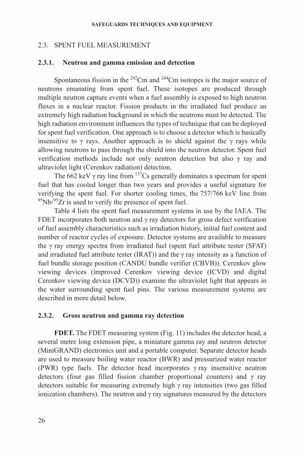
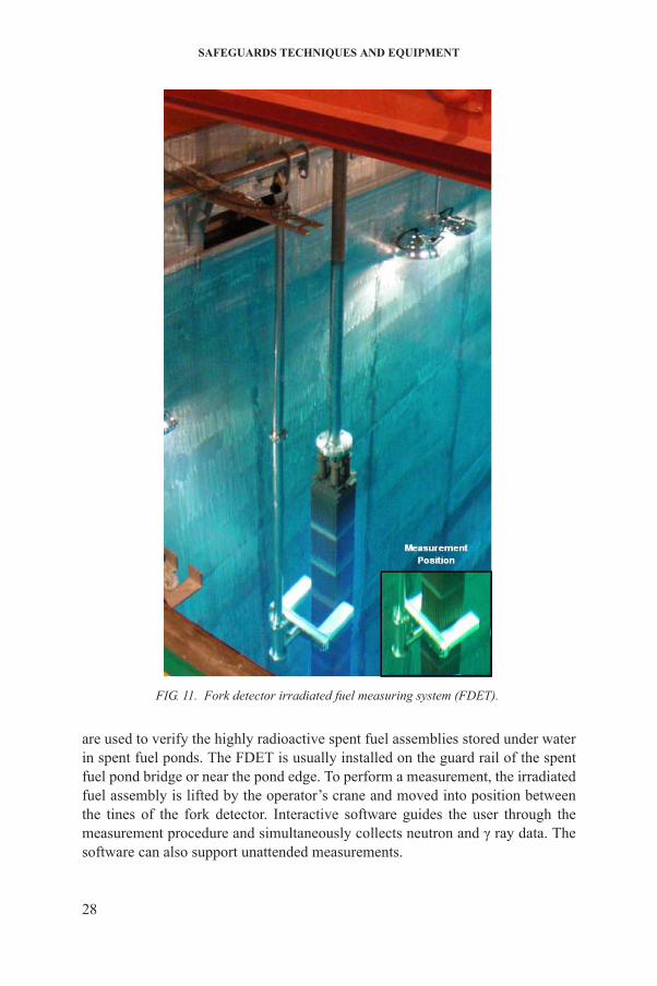
FDET. The FDET measuring system (Fig. 11) includes the detector head, a several metre long extension pipe, a miniature gamma ray and neutron detector
26
(MiniGRAND) electronics unit and a portable computer. Separate detector heads are used to measure boiling water reactor (BWR) and pressurized water reactor (PWR) type fuels. The detector head incorporates γ ray insensitive neutron detectors (four gas filled fission chamber proportional counters) and γ ray detectors suitable for measuring extremely high γ ray intensities (two gas filled ionization chambers). The neutron and γ ray signatures measured by the detectors
NON-DESTRUCTIVE ANALYSIS
TABLE 4. SPENT FUEL MEASUREMENT SYSTEMS
Code Equipment name Description/primary application
AEFC Advanced experimental fuel counter
Characterization of spent fuel from research reactors stored under water
CBVB CANDU bundle verifier Verification of the presence of CANDU fuel bundles stored in either stacks or baskets in a spent fuel pond
CRPS Cask radiation profiling system for dry storage casks
Gross defect device takes radiation profiles from spent fuel storage containers forre-verification
DCVD Digital Cerenkov viewing device
Highly sensitive digital device for viewing Cerenkov light from long cooled, low burnup fuel
FDET Fork detector irradiated fuel measuring system
Detector system that straddles light water reactor fuel assemblies with pairs of neutron and γ ray detectors. Gross γ ray and neutron intensities and ratios of intensities can give specific information on the fuel assembly
ICVD Improved Cerenkov viewing device
Hand-held light intensifying device optimized to view Cerenkov light (near ultraviolet) in a spent fuel storage pond. System can be usedin a lighted area. Primarily used to identify irradiated light water reactor fuel assemblies
IRAT Irradiated fuel attribute tester Gross defect device used for verifying fission product presence in an irradiated fuel assembly
NGAT Neutron and gamma attribute tester
Gross defect device used for verifying spent fuel assemblies, fresh MOX fuel assemblies and open or closed containers holding various radiated and non-irradiated materials including non-fuel items
SFAT Spent fuel attribute tester Gross defect device used for verifying the presence of fission product or activation product at the top of the irradiated fuel assembly
SFCC Spent fuel coincident counter Underwater verification of Pu in canned fast
27
breeder reactor spent fuel.
SMOPY Safeguards MOX python Gross defect device combines gross neutron counting with low level γ spectroscopyto characterize any kind of spent fuel without movement of spent fuel
SAFEGUARDS TECHNIQUES AND EQUIPMENT
are used to verify the highly radioactive spent fuel assemblies stored under water
FIG. 11. Fork detector irradiated fuel measuring system (FDET).
28
in spent fuel ponds. The FDET is usually installed on the guard rail of the spent fuel pond bridge or near the pond edge. To perform a measurement, the irradiated fuel assembly is lifted by the operator’s crane and moved into position between the tines of the fork detector. Interactive software guides the user through the measurement procedure and simultaneously collects neutron and γ ray data. The software can also support unattended measurements.
NON-DESTRUCTIVE ANALYSIS
The ratio of the neutron to γ ray data, when combined with other, complementary information, is used to characterize a particular type of fuel assembly, giving information related to its neutron exposure in the reactor, its initial fissile fuel content and its irradiation history (e.g. the number of cycles for which the assembly was in the reactor). Passive γ emission tomography, currently being tested with the help of several MSSPs, is projected to be able to detect defects at the pin level.
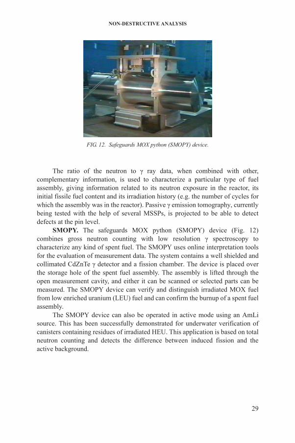
SMOPY. The safeguards MOX python (SMOPY) device (Fig. 12) combines gross neutron counting with low resolution γ spectroscopy to characterize any kind of spent fuel. The SMOPY uses online interpretation tools for the evaluation of measurement data. The system contains a well shielded and collimated CdZnTe γ detector and a fission chamber. The device is placed over the storage hole of the spent fuel assembly. The assembly is lifted through the open measurement cavity, and either it can be scanned or selected parts can be measured. The SMOPY device can verify and distinguish irradiated MOX fuel from low enriched uranium (LEU) fuel and can confirm the burnup of a spent fuel assembly.
The SMOPY device can also be operated in active mode using an AmLi source. This has been successfully demonstrated for underwater verification of canisters containing residues of irradiated HEU. This application is based on total
FIG. 12. Safeguards MOX python (SMOPY) device.
29
neutron counting and detects the difference between induced fission and the active background.
SAFEGUARDS TECHNIQUES AND EQUIPMENT
2.3.3. Gamma ray energy spectral analysis
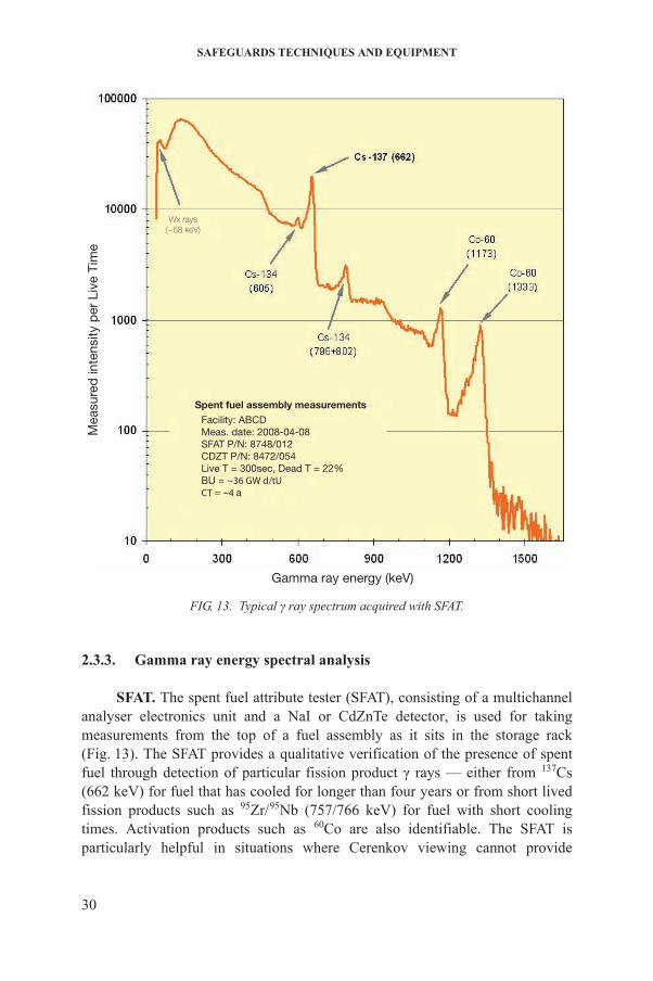
SFAT. The spent fuel attribute tester (SFAT), consisting of a multichannel analyser electronics unit and a NaI or CdZnTe detector, is used for taking measurements from the top of a fuel assembly as it sits in the storage rack
Gamma ray energy (keV)
Mea
sure
d in
tens
ity p
er L
ive
Tim
e
Wx rays(~58 keV)
Spent fuel assembly measurements Facility: ABCD Meas. date: 2008-04-08 SFAT P/N: 8748/012 CDZT P/N: 8472/054 Live T = 300sec, Dead T = 22% BU = ~36 GW d/tU CT = ~4 a
FIG. 13. Typical γ ray spectrum acquired with SFAT.
30
(Fig. 13). The SFAT provides a qualitative verification of the presence of spent fuel through detection of particular fission product γ rays — either from 137Cs (662 keV) for fuel that has cooled for longer than four years or from short lived fission products such as 95Zr/95Nb (757/766 keV) for fuel with short cooling times. Activation products such as 60Co are also identifiable. The SFAT is particularly helpful in situations where Cerenkov viewing cannot provide
NON-DESTRUCTIVE ANALYSIS
verification (e.g. when Cerenkov radiation is weak because the spent fuel has low burnup and/or a long cooling time, or when the water in the storage pond is insufficiently clear). The SFAT detector and its lead shielding are housed in a watertight stainless steel container which is submerged in a storage pond and positioned over the item to be examined. A watertight collimator pipe is attached below the detector housing to permit only radiation from the principal assembly, rather than from adjacent assemblies, to reach the detector. A multichannel analyser provides for the acquisition, analysis and archiving of data and supplies power to the detector. The intensity of the selected γ rays from a specific fuel assembly is compared with the spectrum from the gap separating the assembly from its neighbour, to confirm the presence of fission or activation products in the measured assembly.
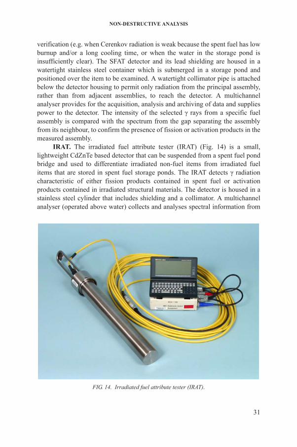
IRAT. The irradiated fuel attribute tester (IRAT) (Fig. 14) is a small, lightweight CdZnTe based detector that can be suspended from a spent fuel pond bridge and used to differentiate irradiated non-fuel items from irradiated fuel items that are stored in spent fuel storage ponds. The IRAT detects γ radiation characteristic of either fission products contained in spent fuel or activation products contained in irradiated structural materials. The detector is housed in a stainless steel cylinder that includes shielding and a collimator. A multichannel analyser (operated above water) collects and analyses spectral information from
31
FIG. 14. Irradiated fuel attribute tester (IRAT).
SAFEGUARDS TECHNIQUES AND EQUIPMENT
the irradiated item. The presence of fission product isotopes, such as 137Cs, 134Cs, 144Pr and 154Eu, is used to confirm the irradiated fuel characteristics. In the case of a structural item, the presence of certain isotopes, such as 60Co, indicates prior exposure to a significant neutron flux. Measurement with the IRAT requires movement of the spent fuel, as the detector approaches the item from the side.
NGAT. The neutron and gamma attribute tester (NGAT) is a compact, universal instrument used for underwater verification of spent fuel assemblies, fresh MOX fuel assemblies, and open or closed containers holding various irradiated and non-irradiated materials including non-fuel items. The equipment’s compact and lightweight design permits the user to easily handle it from the spent fuel pond bridge. The NGAT performs both neutron and γ measurements for gross defect verification. The instrument can be equipped with either a fission chamber or a 10B detector for neutron counting, as well as with a collimated and shielded CdZnTe detector for γ spectroscopy.
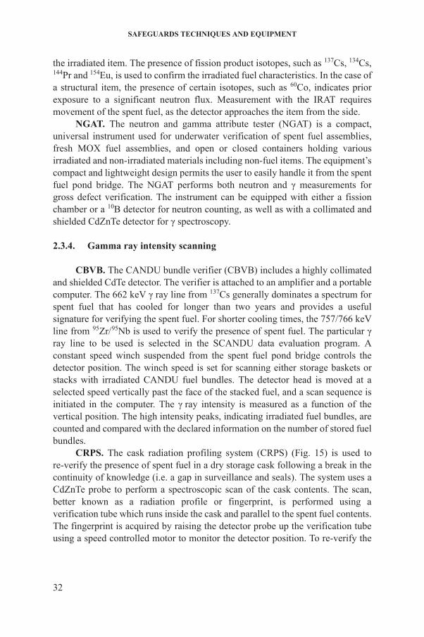
2.3.4. Gamma ray intensity scanning
CBVB. The CANDU bundle verifier (CBVB) includes a highly collimated and shielded CdTe detector. The verifier is attached to an amplifier and a portable computer. The 662 keV γ ray line from 137Cs generally dominates a spectrum for spent fuel that has cooled for longer than two years and provides a useful signature for verifying the spent fuel. For shorter cooling times, the 757/766 keV line from 95Zr/95Nb is used to verify the presence of spent fuel. The particular γ ray line to be used is selected in the SCANDU data evaluation program. A constant speed winch suspended from the spent fuel pond bridge controls the detector position. The winch speed is set for scanning either storage baskets or stacks with irradiated CANDU fuel bundles. The detector head is moved at a selected speed vertically past the face of the stacked fuel, and a scan sequence is initiated in the computer. The γ ray intensity is measured as a function of the vertical position. The high intensity peaks, indicating irradiated fuel bundles, are counted and compared with the declared information on the number of stored fuel bundles.
CRPS. The cask radiation profiling system (CRPS) (Fig. 15) is used to re-verify the presence of spent fuel in a dry storage cask following a break in the continuity of knowledge (i.e. a gap in surveillance and seals). The system uses a
32
CdZnTe probe to perform a spectroscopic scan of the cask contents. The scan, better known as a radiation profile or fingerprint, is performed using a verification tube which runs inside the cask and parallel to the spent fuel contents. The fingerprint is acquired by raising the detector probe up the verification tube using a speed controlled motor to monitor the detector position. To re-verify the

NON-DESTRUCTIVE ANALYSIS
33
cask contents, the fingerprint is compared with a baseline fingerprint.Consistency between the fingerprints indicates that the spent fuel remains present and undisturbed. A database has been developed for storage and evaluation of fingerprints to secure and compare fingerprints while taking into account decay
FIG. 15. Cask radiation profiling system (CRPS).

SAFEGUARDS TECHNIQUES AND EQUIPMENT
and differences in the measurement hardware configuration. The CRPS can be run with a pair of detectors to perform neutron (fission chamber) and γ profiling.
OFPS. The optical fibre radiation probe system (OFPS) performs gross γ measurements supporting the re-verification of CANDU spent fuel bundles stored in the spent fuel bay without requiring movement of the horizontal storage trays. The OFPS consists of a scanning actuator, an optical fibre scintillator coupled to a flexible optical fibre, data acquisition electronics and a personal computer. The use of an optical fibre scintillator for CANDU spent fuel verification has the benefit of detecting gross γ rays in storage ponds without being hindered by the funnel structure. Gamma rays from the spent fuel interact with the optical fibre scintillation media to produce ionization, which subsequently leads to the emission of fluorescent light (~400 nm) of the doped Ce3+ in the optical fibre.
2.3.5. Neutron coincidence methods
AEFC. The advanced experimental fuel counter (AEFC) is used for characterization of spent fuel from research reactors stored under water. The AEFC can be operated in either passive neutron mode or active neutron mode, using an AmLi neutron source to generate fission in the fuel item. Radiation tolerant 3He tubes are embedded in the moderator, forming two different measurement sets. One set (the inner row) measures neutron coincidences to distinguish fission neutrons from background radiation. The second set (the outer row) is placed farther back within the polyethylene moderator, and its signal is approximately proportional to the fission rate in the fuel item.
SFCC. The spent fuel coincident counter (SFCC) is an underwater neutron coincident counter for the verification of operator declared plutonium content in canned fast breeder reactor spent fuel. A single ionization chamber measures the γ ray dose from the spent fuel to determine the appropriate operational parameters to avoid γ ray pile effects in the 3He tubes. The plutonium isotopics are calculated based on a validated burnup chains code. Specially developed iterative software in combination with Monte Carlo N particle transport code (MCNP) modelling converts the measured single and double neutron count rates to plutonium mass. The SFCC easily distinguishes irradiated fuel from non-fuel items which are loaded into the reactor to replace discharged assemblies.
34
2.3.6. Cerenkov radiation detection
ICVD, DCVD. The improved Cerenkov viewing device (ICVD) and the digital Cerenkov viewing device (DCVD) are image intensifier viewing devices that are sensitive to ultraviolet radiation in the water surrounding spent fuel
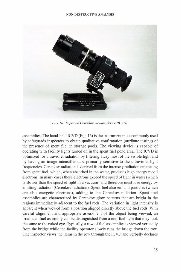
NON-DESTRUCTIVE ANALYSIS
assemblies. The hand-held ICVD (Fig. 16) is the instrument most commonly used by safeguards inspectors to obtain qualitative confirmation (attribute testing) of the presence of spent fuel in storage pools. The viewing device is capable of operating with facility lights turned on in the spent fuel pond area. The ICVD is optimized for ultraviolet radiation by filtering away most of the visible light and by having an image intensifier tube primarily sensitive to the ultraviolet light frequencies. Cerenkov radiation is derived from the intense γ radiation emanating from spent fuel, which, when absorbed in the water, produces high energy recoil electrons. In many cases these electrons exceed the speed of light in water (which is slower than the speed of light in a vacuum) and therefore must lose energy by emitting radiation (Cerenkov radiation). Spent fuel also emits β particles (which are also energetic electrons), adding to the Cerenkov radiation. Spent fuel assemblies are characterized by Cerenkov glow patterns that are bright in the regions immediately adjacent to the fuel rods. The variation in light intensity is
FIG. 16. Improved Cerenkov viewing device (ICVD).
35
apparent when viewed from a position aligned directly above the fuel rods. With careful alignment and appropriate assessment of the object being viewed, an irradiated fuel assembly can be distinguished from a non-fuel item that may look the same to the naked eye. Typically, a row of fuel assemblies is viewed vertically from the bridge while the facility operator slowly runs the bridge down the row. One inspector views the items in the row through the ICVD and verbally declares
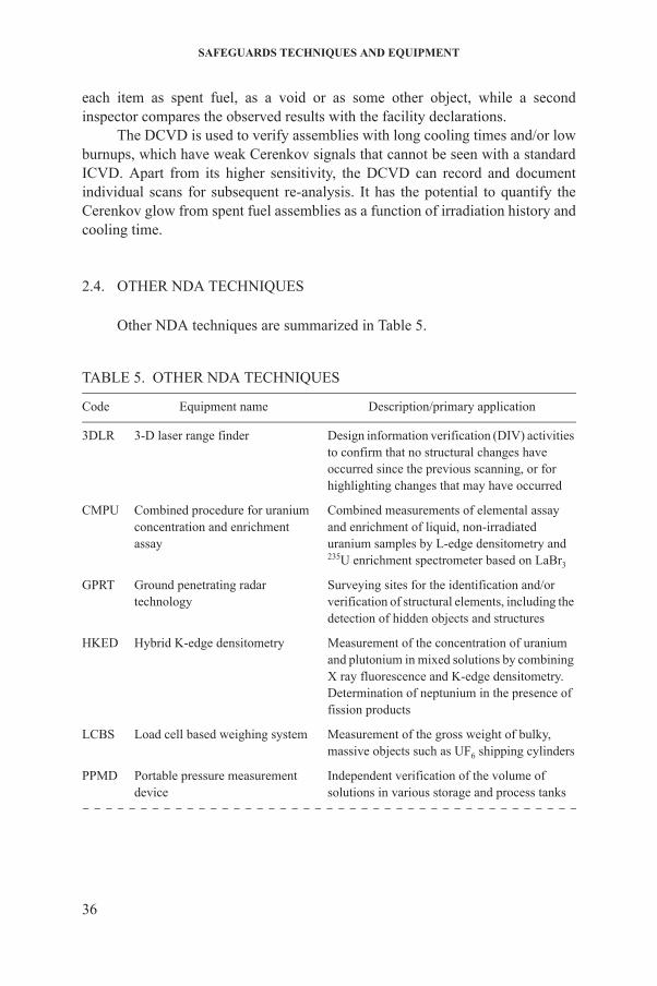
SAFEGUARDS TECHNIQUES AND EQUIPMENT
each item as spent fuel, as a void or as some other object, while a second inspector compares the observed results with the facility declarations.
The DCVD is used to verify assemblies with long cooling times and/or low burnups, which have weak Cerenkov signals that cannot be seen with a standard ICVD. Apart from its higher sensitivity, the DCVD can record and document individual scans for subsequent re-analysis. It has the potential to quantify the Cerenkov glow from spent fuel assemblies as a function of irradiation history and cooling time.
2.4. OTHER NDA TECHNIQUES
Other NDA techniques are summarized in Table 5.
TABLE 5. OTHER NDA TECHNIQUES
Code Equipment name Description/primary application
3DLR 3-D laser range finder Design information verification (DIV) activities to confirm that no structural changes have occurred since the previous scanning, or for highlighting changes that may have occurred
CMPU Combined procedure for uranium concentration and enrichment assay
Combined measurements of elemental assay and enrichment of liquid, non-irradiated uranium samples by L-edge densitometry and 235U enrichment spectrometer based on LaBr3
GPRT Ground penetrating radar technology
Surveying sites for the identification and/or verification of structural elements, including the detection of hidden objects and structures
HKED Hybrid K-edge densitometry Measurement of the concentration of uranium and plutonium in mixed solutions by combining X ray fluorescence and K-edge densitometry.Determination of neptunium in the presence of fission products
LCBS Load cell based weighing system Measurement of the gross weight of bulky, massive objects such as UF6 shipping cylinders
36
PPMD Portable pressure measurement device
Independent verification of the volume of solutions in various storage and process tanks
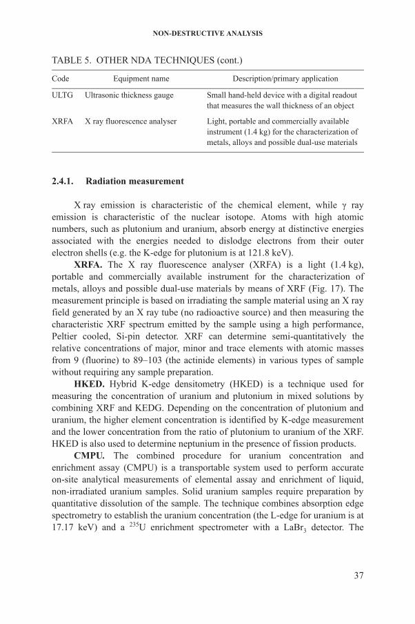
NON-DESTRUCTIVE ANALYSIS
2.4.1. Radiation measurement
X ray emission is characteristic of the chemical element, while γ ray emission is characteristic of the nuclear isotope. Atoms with high atomic numbers, such as plutonium and uranium, absorb energy at distinctive energies associated with the energies needed to dislodge electrons from their outer electron shells (e.g. the K-edge for plutonium is at 121.8 keV).
XRFA. The X ray fluorescence analyser (XRFA) is a light (1.4 kg), portable and commercially available instrument for the characterization of metals, alloys and possible dual-use materials by means of XRF (Fig. 17). The measurement principle is based on irradiating the sample material using an X ray field generated by an X ray tube (no radioactive source) and then measuring the characteristic XRF spectrum emitted by the sample using a high performance, Peltier cooled, Si-pin detector. XRF can determine semi-quantitatively the relative concentrations of major, minor and trace elements with atomic masses from 9 (fluorine) to 89–103 (the actinide elements) in various types of sample without requiring any sample preparation.
HKED. Hybrid K-edge densitometry (HKED) is a technique used for measuring the concentration of uranium and plutonium in mixed solutions by combining XRF and KEDG. Depending on the concentration of plutonium and uranium, the higher element concentration is identified by K-edge measurement and the lower concentration from the ratio of plutonium to uranium of the XRF. HKED is also used to determine neptunium in the presence of fission products.
CMPU. The combined procedure for uranium concentration and enrichment assay (CMPU) is a transportable system used to perform accurate
ULTG Ultrasonic thickness gauge Small hand-held device with a digital readout that measures the wall thickness of an object
XRFA X ray fluorescence analyser Light, portable and commercially available instrument (1.4 kg) for the characterization of metals, alloys and possible dual-use materials
TABLE 5. OTHER NDA TECHNIQUES (cont.)
Code Equipment name Description/primary application
37
on-site analytical measurements of elemental assay and enrichment of liquid, non-irradiated uranium samples. Solid uranium samples require preparation by quantitative dissolution of the sample. The technique combines absorption edge spectrometry to establish the uranium concentration (the L-edge for uranium is at 17.17 keV) and a 235U enrichment spectrometer with a LaBr3 detector. The

SAFEGUARDS TECHNIQUES AND EQUIPMENT
L-edge technique uses a small X ray generator of low energy and an ultra-high resolution silicon γ detector operated under modest Peltier cooling.
2.4.2. Physical property measurement
The IAEA also uses equipment to measure such quantities as the weight of an object (LCBS), the wall thickness of a container (ULTG), physical sizes (3DLR), electromagnetic reflections (GPRT) and the liquid level in a tank (PPMD).
LCBS. The load cell based weighing system (LCBS) (Fig. 18) operates in two load ranges of up to 5000 and 20 000 kg and provides a convenient and rapid means of determining the gross weight of bulky, massive objects such as UF6
shipping cylinders. The load cell construction includes two shackles separated by a load supporting element that is bonded to a strain gauge. When a load is lifted with the hoist, the strain gauge deforms, changing its electrical resistance. The resistance change is converted into a weight displayed on a digital readout unit
FIG. 17. X ray fluorescence analyser (XRFA).
38
that is attached through a cable to the load cell. Typically, gross weights are determined with this system to an accuracy of better than 0.1%.
ULTG. The ultrasonic thickness gauge (ULTG) is a small hand-held device with a digital readout that measures the wall thickness of an object based on the round trip flight time of ultrasonic waves that are reflected from the inner wall. The thickness information is sometimes needed to adjust for radiation attenuation
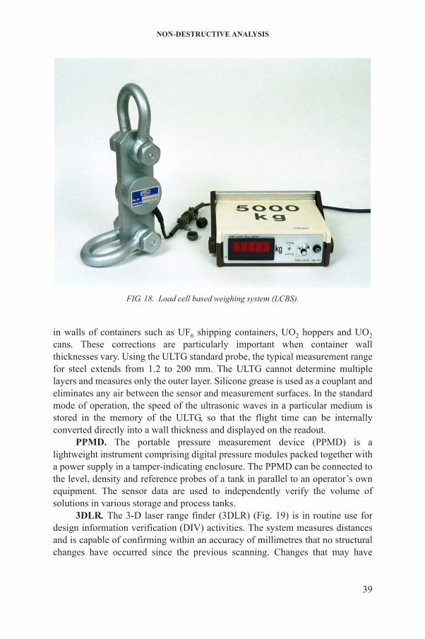
NON-DESTRUCTIVE ANALYSIS
in walls of containers such as UF6 shipping containers, UO2 hoppers and UO2
cans. These corrections are particularly important when container wall thicknesses vary. Using the ULTG standard probe, the typical measurement range for steel extends from 1.2 to 200 mm. The ULTG cannot determine multiple layers and measures only the outer layer. Silicone grease is used as a couplant and eliminates any air between the sensor and measurement surfaces. In the standard mode of operation, the speed of the ultrasonic waves in a particular medium is stored in the memory of the ULTG, so that the flight time can be internally converted directly into a wall thickness and displayed on the readout.
PPMD. The portable pressure measurement device (PPMD) is a lightweight instrument comprising digital pressure modules packed together with a power supply in a tamper-indicating enclosure. The PPMD can be connected to the level, density and reference probes of a tank in parallel to an operator’s own
FIG. 18. Load cell based weighing system (LCBS).
39
equipment. The sensor data are used to independently verify the volume of solutions in various storage and process tanks.
3DLR. The 3-D laser range finder (3DLR) (Fig. 19) is in routine use for design information verification (DIV) activities. The system measures distances and is capable of confirming within an accuracy of millimetres that no structural changes have occurred since the previous scanning. Changes that may have
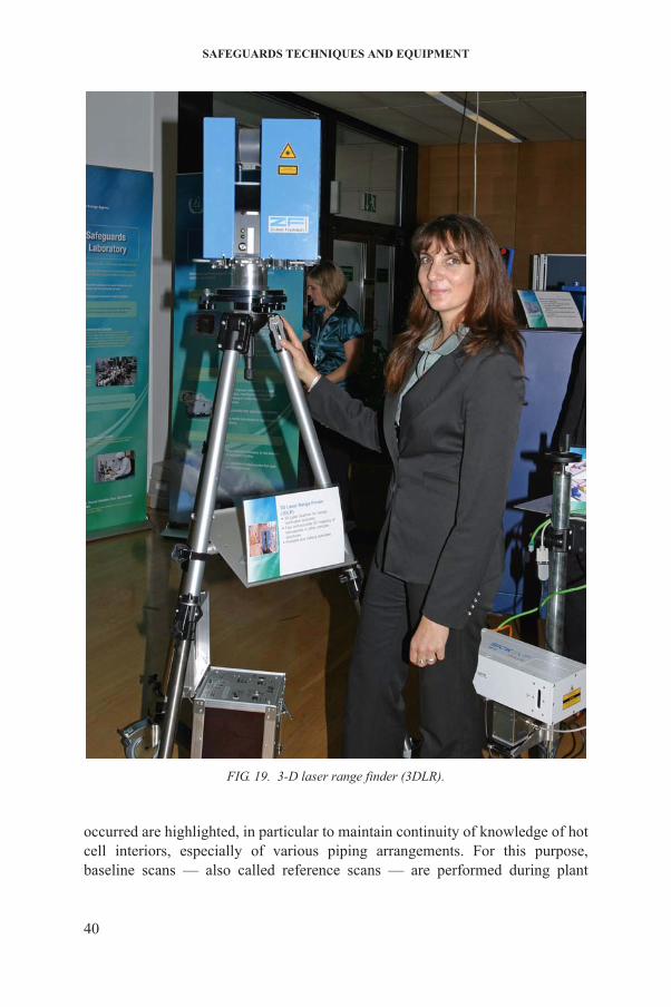
SAFEGUARDS TECHNIQUES AND EQUIPMENT
40
occurred are highlighted, in particular to maintain continuity of knowledge of hot cell interiors, especially of various piping arrangements. For this purpose, baseline scans — also called reference scans — are performed during plant
FIG. 19. 3-D laser range finder (3DLR).

NON-DESTRUCTIVE ANALYSIS
construction; subsequent verification scans taken during periodic inspection activities are compared with the original references.
GPRT. Ground penetrating radar technology (GPRT) is based on the transmission and reflection of electromagnetic pulses and represents a non-intrusive means of surveying sites for the identification and/or verification of structural elements. GPRT uses pulses of electromagnetic radiation in the microwave band (UHF/VHF frequencies) of the radio spectrum and reads the reflected signal to detect subsurface structures and objects without drilling, probing or otherwise breaking the ground surface. Applications include the detection of hidden objects and structures.
41

3. UNATTENDED MONITORING
Unattended monitoring systems (UMSs) run 24 hours a day, 365 days a year without requiring the presence of an inspector in the field. They continuously perform a wide variety of qualitative or quantitative measurements of processes throughout the nuclear fuel cycle, including:
— Uranium enrichment; — Conversion;— Fuel fabrication; — Reactor operation (light water reactors (LWRs), heavy water reactors
(HWRs), fast reactors, research reactors);— Spent fuel reprocessing;— Spent fuel management (wet storage, dry storage);— Intermediate and high active waste management.
UMSs can perform the following measurement tasks, depending on the safeguards needs:
— Monitoring fresh and/or spent fuel assembly/bundle movements within a facility or between spent fuel ponds and dry storage silos;
— Characterizing fresh MOX nuclear fuel, spent fuel assemblies and waste; — Measuring the mass of nuclear material present in MOX powder, in nuclear
waste or in solution;— Determining vessel volume, weight, linear position, temperature, reactor
power and other measurements.
UMSs apply NDA measurement methods as described earlier, adapted to the specific measurement requirements. Several families of UMSs can be distinguished, according to the technology they are based on:
— MiniGRAND based system (MGBS);— Shift register based system (SRBS);— VXI integrated fuel monitor (VIFM);
42
— Silo entry gate monitor (SEGM);— Mobile unit neutron detector (MUND);— Advanced thermohydraulic power monitor (ATPM);— ‘Other’, including γ spectrometry based systems (on-line enrichment monitor
(OLEM), etc.), special nuclear measurement techniques (plutonium inventory monitoring system (PIMS)) and non-nuclear measurement systems
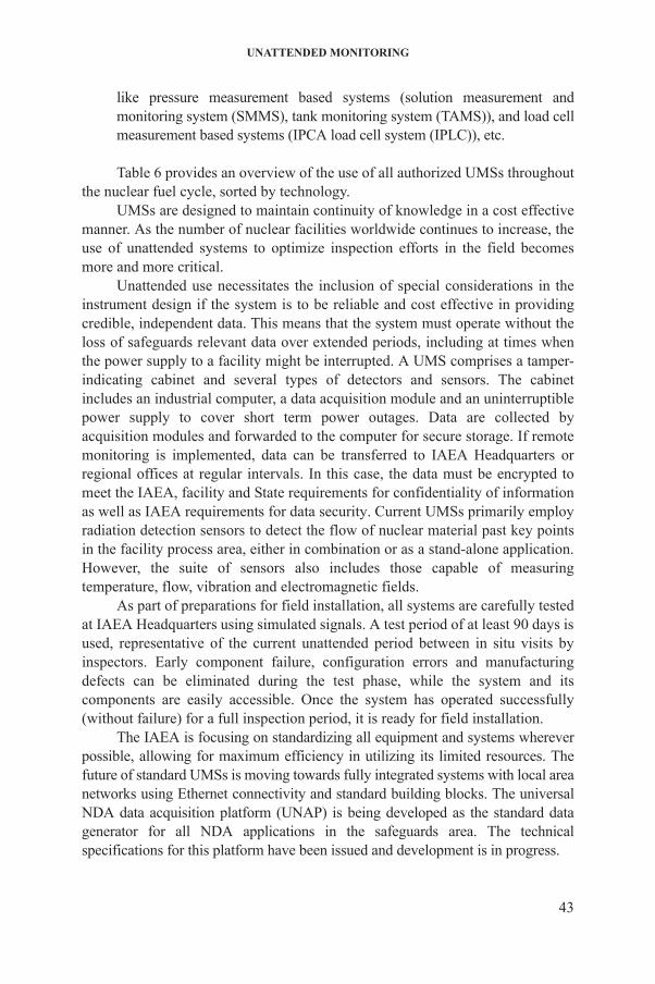
UNATTENDED MONITORING
like pressure measurement based systems (solution measurement and monitoring system (SMMS), tank monitoring system (TAMS)), and load cell measurement based systems (IPCA load cell system (IPLC)), etc.
Table 6 provides an overview of the use of all authorized UMSs throughout the nuclear fuel cycle, sorted by technology.
UMSs are designed to maintain continuity of knowledge in a cost effective manner. As the number of nuclear facilities worldwide continues to increase, the use of unattended systems to optimize inspection efforts in the field becomes more and more critical.
Unattended use necessitates the inclusion of special considerations in the instrument design if the system is to be reliable and cost effective in providing credible, independent data. This means that the system must operate without the loss of safeguards relevant data over extended periods, including at times when the power supply to a facility might be interrupted. A UMS comprises a tamper- indicating cabinet and several types of detectors and sensors. The cabinet includes an industrial computer, a data acquisition module and an uninterruptible power supply to cover short term power outages. Data are collected by acquisition modules and forwarded to the computer for secure storage. If remote monitoring is implemented, data can be transferred to IAEA Headquarters or regional offices at regular intervals. In this case, the data must be encrypted to meet the IAEA, facility and State requirements for confidentiality of information as well as IAEA requirements for data security. Current UMSs primarily employ radiation detection sensors to detect the flow of nuclear material past key points in the facility process area, either in combination or as a stand-alone application. However, the suite of sensors also includes those capable of measuring temperature, flow, vibration and electromagnetic fields.
As part of preparations for field installation, all systems are carefully tested at IAEA Headquarters using simulated signals. A test period of at least 90 days is used, representative of the current unattended period between in situ visits by inspectors. Early component failure, configuration errors and manufacturing defects can be eliminated during the test phase, while the system and its components are easily accessible. Once the system has operated successfully (without failure) for a full inspection period, it is ready for field installation.
The IAEA is focusing on standardizing all equipment and systems wherever
43
possible, allowing for maximum efficiency in utilizing its limited resources. The future of standard UMSs is moving towards fully integrated systems with local area networks using Ethernet connectivity and standard building blocks. The universal NDA data acquisition platform (UNAP) is being developed as the standard data generator for all NDA applications in the safeguards area. The technical specifications for this platform have been issued and development is in progress.
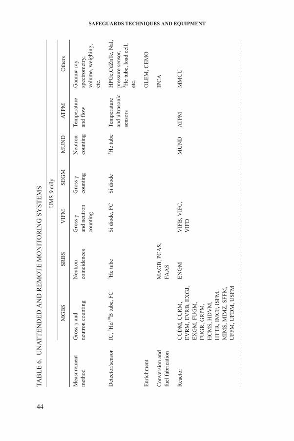
SAFEGUARDS TECHNIQUES AND EQUIPMENT
TE
ND
ED
AN
D R
EM
OT
E M
ON
ITO
RIN
G S
YS
TE
MS
UM
S fa
mil
y
MG
BS
SR
BS
VIF
MS
EG
MM
UN
DA
TP
MO
ther
s
Gro
ss γ
and
neut
ron
coun
ting
Neu
tron
coin
cide
nces
Gro
ss γ
and
neut
ron
coun
ting
Gro
ss γ
coun
ting
Neu
tron
coun
ting
Tem
pera
ture
and
flow
Gam
ma
ray
spec
trom
etry
,vo
lum
e, w
eigh
ing,
etc.
IC, 3 H
e/10
B tu
be, F
C3 H
e tu
beS
i dio
de, F
CS
i dio
de3 H
e tu
beTe
mpe
ratu
re
and
ultr
ason
ic
sens
ors
HP
Ge,
CdZ
nTe,
NaI
,pr
essu
re s
enso
r,3 H
e tu
be, l
oad
cell,
etc.
OL
EM
, CE
MO
MA
GB
, PC
AS
,FA
AS
IPC
A
CC
DM
, CC
RM
,E
VR
M, E
VR
B, E
XG
J,
EX
GM
, FU
GM
,F
UG
R, G
RP
M,
HC
MS
, HD
VM
,H
TT
R, I
MC
F, I
SF
M,
MIM
S, M
IMZ
, SF
FM
,U
FFM
, UFD
M, U
SFM
EN
GM
VIF
B, V
IFC
,V
IFD
MU
ND
AT
PMM
MC
U
44
TAB
LE
6.
UN
AT
Mea
sure
men
tm
etho
d
Det
ecto
r/se
nsor
Enr
ichm
ent
Con
vers
ion
and
fuel
fab
rica
tion
Rea
ctor
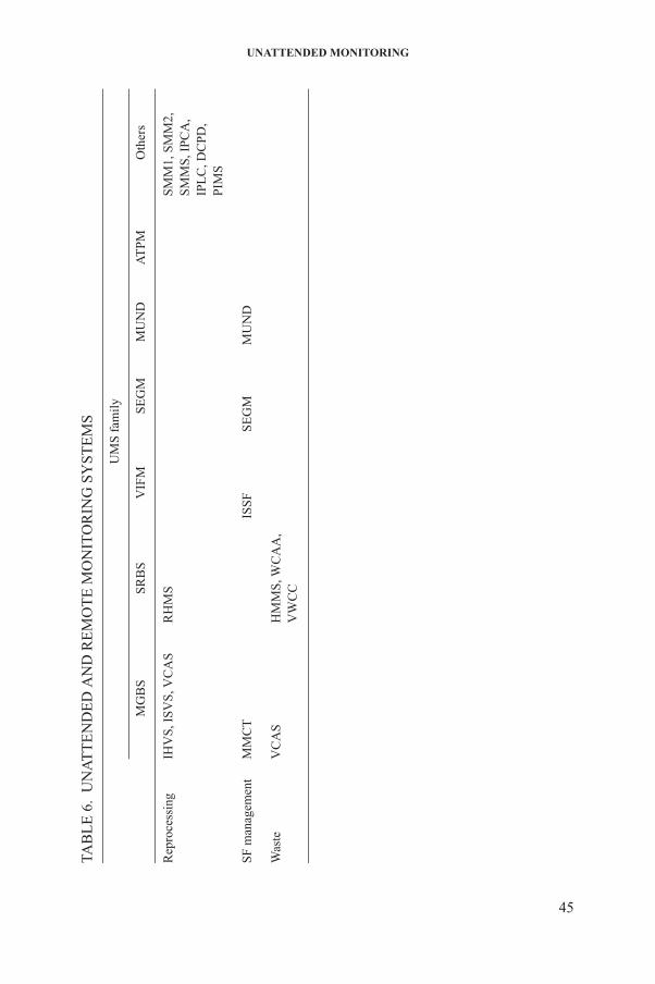
UNATTENDED MONITORING
IHV
S, I
SV
S, V
CA
SR
HM
SS
MM
1, S
MM
2,
SM
MS
, IP
CA
,IP
LC
, DC
PD
,P
IMS
MM
CT
ISS
FS
EG
MM
UN
D
VC
AS
HM
MS,
WC
AA
,V
WC
C
TE
ND
ED
AN
D R
EM
OT
E M
ON
ITO
RIN
G S
YS
TE
MS
UM
S fa
mil
y
MG
BS
SR
BS
VIF
MS
EG
MM
UN
DA
TP
MO
ther
s
45
Rep
roce
ssin
g
SF
man
agem
ent
Was
te
TAB
LE
6.
UN
AT
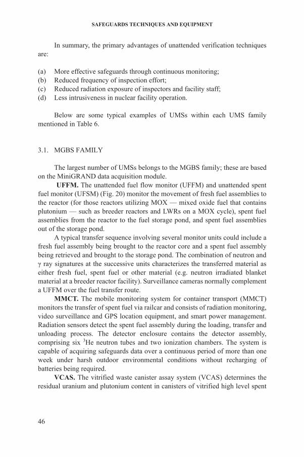
SAFEGUARDS TECHNIQUES AND EQUIPMENT
In summary, the primary advantages of unattended verification techniques are:
(a) More effective safeguards through continuous monitoring;(b) Reduced frequency of inspection effort;(c) Reduced radiation exposure of inspectors and facility staff;(d) Less intrusiveness in nuclear facility operation.
Below are some typical examples of UMSs within each UMS family mentioned in Table 6.
3.1. MGBS FAMILY
The largest number of UMSs belongs to the MGBS family; these are based on the MiniGRAND data acquisition module.
UFFM. The unattended fuel flow monitor (UFFM) and unattended spent fuel monitor (UFSM) (Fig. 20) monitor the movement of fresh fuel assemblies to the reactor (for those reactors utilizing MOX — mixed oxide fuel that contains plutonium — such as breeder reactors and LWRs on a MOX cycle), spent fuel assemblies from the reactor to the fuel storage pond, and spent fuel assemblies out of the storage pond.
A typical transfer sequence involving several monitor units could include a fresh fuel assembly being brought to the reactor core and a spent fuel assembly being retrieved and brought to the storage pond. The combination of neutron and γ ray signatures at the successive units characterizes the transferred material as either fresh fuel, spent fuel or other material (e.g. neutron irradiated blanket material at a breeder reactor facility). Surveillance cameras normally complement a UFFM over the fuel transfer route.
MMCT. The mobile monitoring system for container transport (MMCT) monitors the transfer of spent fuel via railcar and consists of radiation monitoring, video surveillance and GPS location equipment, and smart power management.Radiation sensors detect the spent fuel assembly during the loading, transfer and unloading process. The detector enclosure contains the detector assembly, comprising six 3He neutron tubes and two ionization chambers. The system is
46
capable of acquiring safeguards data over a continuous period of more than one week under harsh outdoor environmental conditions without recharging of batteries being required.
VCAS. The vitrified waste canister assay system (VCAS) determines the residual uranium and plutonium content in canisters of vitrified high level spent
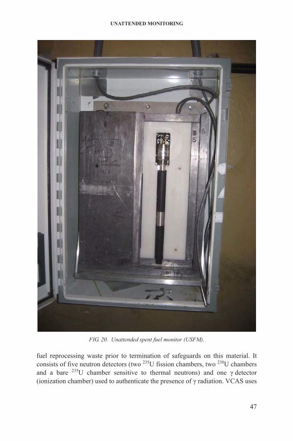
UNATTENDED MONITORING
47
fuel reprocessing waste prior to termination of safeguards on this material. It consists of five neutron detectors (two 235U fission chambers, two 238U chambers and a bare 235U chamber sensitive to thermal neutrons) and one γ detector (ionization chamber) used to authenticate the presence of γ radiation. VCAS uses
FIG. 20. Unattended spent fuel monitor (USFM).
SAFEGUARDS TECHNIQUES AND EQUIPMENT
235U fission chambers to determine the 244Cm content by singles (totals) neutron counting. Plutonium and uranium content are calculated from Pu:Cm and U:Cm ratios (determined in the feed solution to the melter). In addition, vitrification of the waste solution is verified by measurement of the neutron spectrum (using the ratio of counting rates in 235U and 238U fission chambers). The neutron radiation data are integrated with data from cameras that monitor the measurement station and verify the canister ID.
3.2. SRBS FAMILY
Unattended monitoring systems in the SRBS family commonly use shift register technology in combination with 3He based detectors to analyse coincidence neutrons detected from fresh plutonium materials. Most of these systems are installed at MOX fuel fabrication and reprocessing plants.
MAGB. The material accountancy glovebox counter (MAGB) measures the plutonium content in specific process containers, handled in the gloveboxes of an automated process. The system consists of two slab detectors viewing the load cell of a process glovebox, where a container filled with either feed powder, pellets or scrap is positioned. A radiation triggered camera identifies the process container and creates a time stamped video ID record. An upgraded version (advanced material accountancy glovebox counter (AMAGB)) employs a HPGe system for the determination of isotopic composition and the uranium to plutonium ratio.
PCAS. The plutonium canister assay system (PCAS) determines the content of plutonium in MOX and pure oxide powders in cans contained in a specific transport container (four cans per canister). The system can be integrated into an operator’s material handling system, and continuous measurement cycles are performed without inspector intervention. A digital camera, automatically triggered by neutrons, records canister IDs, which can be linked to individual measurement cycles. For inventory verification, an inspector provides an electronic list of canisters to be verified and the operator transfers the selected canisters to the PCAS during shift work without an inspector being present. At the end of a verification campaign, an inspector collects the verification data for evaluation. An improved plutonium canister assay (IPCA) system employs three
48
germanium detectors to determine isotopic composition, including the uranium to plutonium ratio. The IPCA is designed to determine the mass of plutonium and uranium in MOX canisters with an uncertainty of less than 0.85% for 5–16 kg of plutonium. This performance significantly reduces the random sample size for destructive analysis.
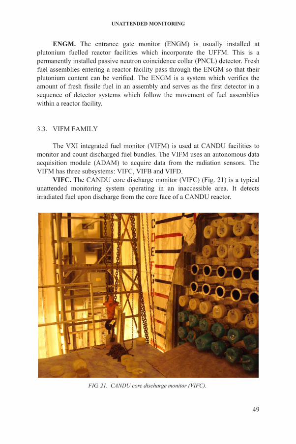
UNATTENDED MONITORING
ENGM. The entrance gate monitor (ENGM) is usually installed at plutonium fuelled reactor facilities which incorporate the UFFM. This is a permanently installed passive neutron coincidence collar (PNCL) detector. Fresh fuel assemblies entering a reactor facility pass through the ENGM so that their plutonium content can be verified. The ENGM is a system which verifies the amount of fresh fissile fuel in an assembly and serves as the first detector in a sequence of detector systems which follow the movement of fuel assemblies within a reactor facility.
3.3. VIFM FAMILY
The VXI integrated fuel monitor (VIFM) is used at CANDU facilities to monitor and count discharged fuel bundles. The VIFM uses an autonomous data acquisition module (ADAM) to acquire data from the radiation sensors. The VIFM has three subsystems: VIFC, VIFB and VIFD.
VIFC. The CANDU core discharge monitor (VIFC) (Fig. 21) is a typical unattended monitoring system operating in an inaccessible area. It detects irradiated fuel upon discharge from the core face of a CANDU reactor.
49
FIG. 21. CANDU core discharge monitor (VIFC).

SAFEGUARDS TECHNIQUES AND EQUIPMENT
Both neutron (normal on power discharge signal) and γ ray intensities are continuously monitored. The inspector is able to review a summary file against the operator declaration and identify any unusual movement associated with fuel bundle discharge. The review software tool validates irradiated fuel discharges both when the reactor is on power and when it is shut down. Because of the linear increase in background signal, the system can also track the operating power level of the reactor.
VIFB. The CANDU spent fuel bundle counter (VIFB) is an unattended system that monitors a strategic location in the spent fuel bundle pathway of an on-load refuelled power reactor. Collimated γ ray detectors detect the fuel bundle as it passes. The proper placement of detectors and use of the appropriate algorithm for the facility enable the device to count the bundles as they pass and record the direction in which they are moving, even when two bundles are moving together, which is normally the case.
VIFD. The CANDU VIFM ‘yes/no’ monitor (VIFD) determines if any irradiated fuel has been discharged through access ports that are not part of the normal discharge path.
3.4. SEGM FAMILY
SEGM. The silo entry gamma monitor (SEGM) (Fig. 22) monitors the loading of dry storage containers into a final silo storage location. The SEGM has a pair of pin diode γ silicon detectors located at different levels in the verification tubes available for each silo. The detectors provide direction sensitive verification of the silo loading and are installed before the start of a transfer campaign. The cables from several silos (up to eight) are routed to a common electronics cabinet, where the resulting data are logged. The data can be extracted either locally or remotely via a standard Ethernet link. After each silo has been completely filled, the detectors are removed by inspectors and replaced with seals, and the top cover is welded.
3.5. MUND FAMILY
50
MUND. The mobile unit for neutron detection (MUND) is an all in one neutron detection system for data collection and storage that is capable of running on battery power. The unit is based on a 3He detector mounted inside a polyethylene moderator slab and integrated with all the supporting electronics inside a single, sealable enclosure. Once installed, a MUND is usually serviced
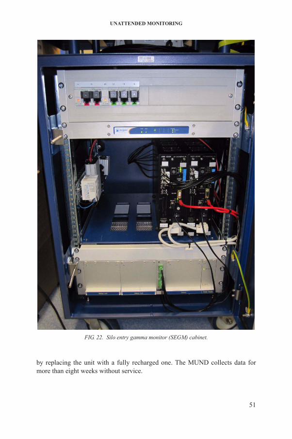
UNATTENDED MONITORING
51
by replacing the unit with a fully recharged one. The MUND collects data for more than eight weeks without service.
FIG. 22. Silo entry gamma monitor (SEGM) cabinet.
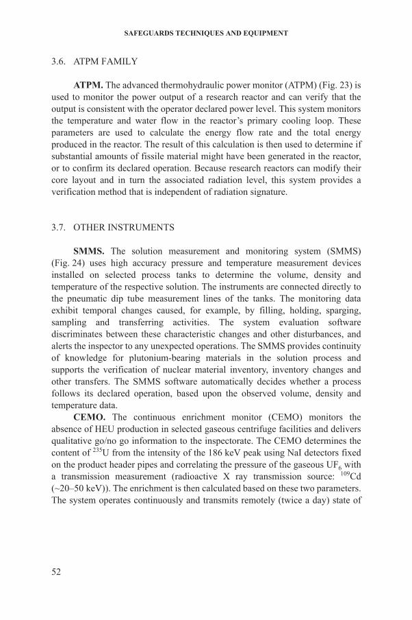
SAFEGUARDS TECHNIQUES AND EQUIPMENT
3.6. ATPM FAMILY
ATPM. The advanced thermohydraulic power monitor (ATPM) (Fig. 23) is used to monitor the power output of a research reactor and can verify that the output is consistent with the operator declared power level. This system monitors the temperature and water flow in the reactor’s primary cooling loop. These parameters are used to calculate the energy flow rate and the total energy produced in the reactor. The result of this calculation is then used to determine if substantial amounts of fissile material might have been generated in the reactor, or to confirm its declared operation. Because research reactors can modify their core layout and in turn the associated radiation level, this system provides a verification method that is independent of radiation signature.
3.7. OTHER INSTRUMENTS
SMMS. The solution measurement and monitoring system (SMMS) (Fig. 24) uses high accuracy pressure and temperature measurement devices installed on selected process tanks to determine the volume, density and temperature of the respective solution. The instruments are connected directly to the pneumatic dip tube measurement lines of the tanks. The monitoring data exhibit temporal changes caused, for example, by filling, holding, sparging, sampling and transferring activities. The system evaluation software discriminates between these characteristic changes and other disturbances, and alerts the inspector to any unexpected operations. The SMMS provides continuity of knowledge for plutonium-bearing materials in the solution process and supports the verification of nuclear material inventory, inventory changes and other transfers. The SMMS software automatically decides whether a process follows its declared operation, based upon the observed volume, density and temperature data.
CEMO. The continuous enrichment monitor (CEMO) monitors the absence of HEU production in selected gaseous centrifuge facilities and delivers qualitative go/no go information to the inspectorate. The CEMO determines the content of 235U from the intensity of the 186 keV peak using NaI detectors fixed on the product header pipes and correlating the pressure of the gaseous UF6 with
109
52
a transmission measurement (radioactive X ray transmission source: Cd (~20–50 keV)). The enrichment is then calculated based on these two parameters. The system operates continuously and transmits remotely (twice a day) state of
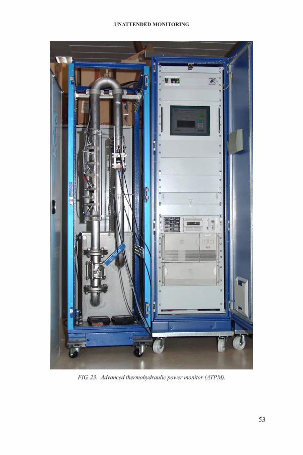
UNATTENDED MONITORING
53
FIG. 23. Advanced thermohydraulic power monitor (ATPM).
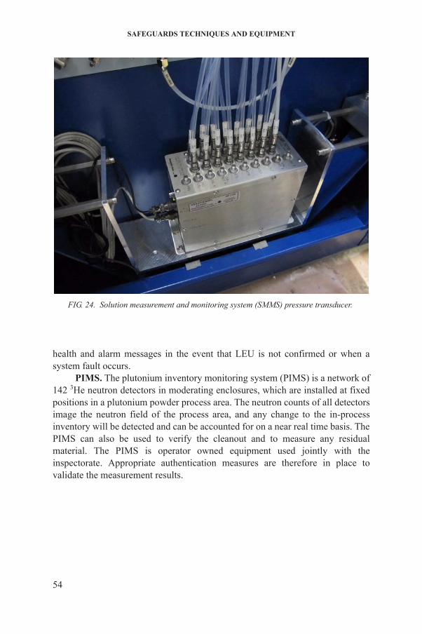
SAFEGUARDS TECHNIQUES AND EQUIPMENT
health and alarm messages in the event that LEU is not confirmed or when a system fault occurs.
PIMS. The plutonium inventory monitoring system (PIMS) is a network of 142 3He neutron detectors in moderating enclosures, which are installed at fixed positions in a plutonium powder process area. The neutron counts of all detectors image the neutron field of the process area, and any change to the in-process inventory will be detected and can be accounted for on a near real time basis. The PIMS can also be used to verify the cleanout and to measure any residual material. The PIMS is operator owned equipment used jointly with the inspectorate. Appropriate authentication measures are therefore in place to validate the measurement results.
FIG. 24. Solution measurement and monitoring system (SMMS) pressure transducer.
54

4. CONTAINMENT AND SURVEILLANCE
Containment and surveillance (C/S) techniques, based mainly on optical surveillance and sealing systems, are applied to supplement nuclear material accountancy by providing means by which access to nuclear material can be controlled and any undeclared movement of nuclear material detected. The IAEA uses C/S techniques extensively because they are flexible and cost effective. They reduce inspection costs and the level of intrusiveness of the IAEA into normal operational activity of nuclear facilities under safeguards. Furthermore, C/S measures are applied in a systematic manner to monitor all diversion paths considered credible at the boundary of a facility, to ensure that transfers of nuclear material take place only at declared key measurement points. This application becomes increasingly important in large facilities where the IAEA’s quantitative safeguards goals are difficult to realize exclusively through conventional nuclear material accountancy measures.
Optical surveillance is most effective in storage areas (such as spent fuel storage ponds) with relatively few activities that could be interpreted as involving the removal of nuclear material. A typical application consists of two or more cameras positioned to completely cover the storage area. The field of view of the cameras is such that any movement of objects that could involve the removal of nuclear material is easily identified. Optical surveillance is intrinsically an unattended operation that may be enhanced by the remote transmission of image data or system operation data (i.e. the status of the surveillance system).
Seals are typically applied to enclosures containing nuclear materials or protecting signals from IAEA UMS/surveillance systems. Seals and their enclosures are designed to indicate tampering, to ensure that nuclear material has not been introduced into or removed from a container, or that data signals have not been tampered with. In addition to tamper indication, sealing systems must be authenticated by providing a unique identity. Most IAEA seals are applied for extended periods, often several months or years. Seals may be either single use (returned to Headquarters for verification) or verifiable in situ. If seals are verifiable in situ then the verification activity must limit radiation exposure of the inspector and be extremely reliable and robust. Seal verification activity consists of carefully examining an item’s enclosure and the seal’s integrity for any sign of
55
tampering.For added confidence in cases where nuclear material is difficult to access,
credible diversion paths are often covered by two C/S devices which are functionally independent and are not subject to a common tampering or failure mode, for example, two different types of seal, seals plus surveillance, or surveillance using two types of equipment based on different techniques.
SAFEGUARDS TECHNIQUES AND EQUIPMENT
4.1. SURVEILLANCE
Surveillance includes both human and instrument observation. Because it is prohibitively expensive to provide round-the-clock human surveillance, the IAEA has developed a range of optical surveillance systems that can provide effective, ongoing surveillance when no inspector is physically present on-site. Unattended optical surveillance techniques are used widely by the IAEA to support and complement nuclear material accountancy and to provide continuity of knowledge about nuclear materials and other items of safeguards significance between on-site inspection visits. Optical surveillance is also used to identify items during unattended NDA measurements and indications of tampering on the instruments in use.
Effective surveillance is achieved when a camera’s field of view covers the entire area of safeguards interest and is able to capture any movement of safeguarded items. Additionally, the picture-taking interval is set to record at least two images should the item be moved, so that its direction of movement can be determined. The image recording frequency may be set at a fixed time interval which is significantly shorter than the fastest removal time, or may be triggered by scene change detection or other external triggers.
Some of the IAEA’s surveillance systems can also transfer data to IAEA Headquarters or to an IAEA regional office automatically.
Surveillance equipment is designed to meet several basic application requirements. Chiefly, those requirements are as follows:
(a) Single camera — for easy to access locations;(b) Single camera — for difficult to access locations;(c) Multi-camera — for larger and more complex facilities;(d) Short term surveillance — for activities that include open core monitoring;(e) Surveillance — for remote monitoring;(f) Underwater closed circuit TV — for attended applications in fuel storage
ponds.
IAEA surveillance equipment has evolved from film cameras through systems based on videotape technology to today’s digital image surveillance (DIS) systems. The evolution of IAEA surveillance equipment has been
56
influenced mostly by strong commercial trends, which dictate the market availability of relevant technologies. With its significant reduction in the number of moving parts, DIS is inherently more reliable than previous film and videotape technologies. Other benefits include enhanced digital data evaluation, assisted review capabilities, improved authentication and encryption, and facilitation of remote monitoring.
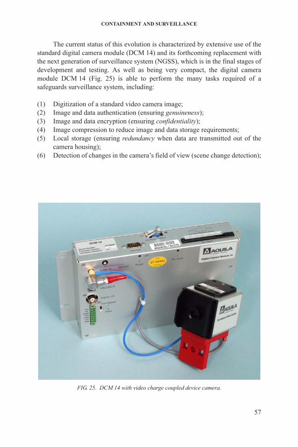
CONTAINMENT AND SURVEILLANCE
The current status of this evolution is characterized by extensive use of the standard digital camera module (DCM 14) and its forthcoming replacement with the next generation of surveillance system (NGSS), which is in the final stages of development and testing. As well as being very compact, the digital camera module DCM 14 (Fig. 25) is able to perform the many tasks required of a safeguards surveillance system, including:
(1) Digitization of a standard video camera image;(2) Image and data authentication (ensuring genuineness);(3) Image and data encryption (ensuring confidentiality);(4) Image compression to reduce image and data storage requirements;(5) Local storage (ensuring redundancy when data are transmitted out of the
camera housing);(6) Detection of changes in the camera’s field of view (scene change detection);
57
FIG. 25. DCM 14 with video charge coupled device camera.
SAFEGUARDS TECHNIQUES AND EQUIPMENT
(7) Power management to ensure maximum possible operation should local power fail;
(8) Secure remote surveillance when connected to a communications server.
Safeguards surveillance systems are almost unique in that the equipment must operate unattended for extended periods in harsh conditions and with a high degree of reliability and security. Despite repeated attempts over the years to identify commercial off-the-shelf equivalents, no immediately suitable systems were identified. Systems that nearly meet IAEA requirements would invariably require some degree of modification, entailing significant additional cost.
Because of its inherent flexibility, the DCM 14 was introduced to consolidate and standardize IAEA surveillance systems. Using the DCM 14 in different configurations, it became possible to assemble single and multiple camera systems for both easy and difficult to access locations from a standard array of basic building blocks. Five basic digital surveillance systems, meeting the full range of safeguards applications, often in difficult environments, were developed based on DCM 14 technology.
Surveillance continues to play an important role in safeguards. Over the past decade there has been a steady increase in the number of camera units deployed in safeguarded facilities.
At the time of writing, the IAEA was maintaining about 1000 cameras connected to 400 surveillance systems on 170 safeguarded sites worldwide. An increasing number of these systems transmit digital images remotely and on a near real time basis from their location to IAEA Headquarters in Vienna. The IAEA instigated the development of the NGSS to replace existing DCM 14 based surveillance systems approaching the end of their expected life cycle. This history and replacement strategy is summarized in Fig. 26.
The replacement of older DCM 14 systems with the NGSS will start in 2012, and the programme is not expected to be fully completed until 2020. Until that time, old and new systems will continue to coexist. Table 7 provides an overview of the IAEA’s main surveillance systems in the coming years.
Equipment has also been developed to provide an increasingly sophisticated review capability for surveillance. Following the same technology trends, review stations have evolved from film review tables through videotape systems (some with advanced features such as scene change detection) to the
58
IAEA’s most recent General Advanced Review Station Software (GARS), which can run on a personal computer equipped with the appropriate digital media peripherals.
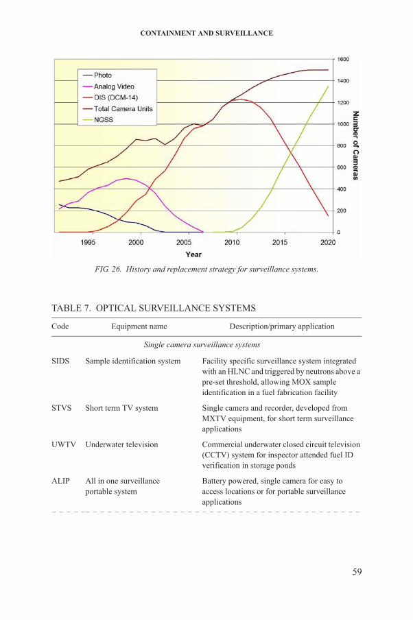
CONTAINMENT AND SURVEILLANCE
TABLE 7. OPTICAL SURVEILLANCE SYSTEMS
Code Equipment name Description/primary application
Single camera surveillance systems
SIDS Sample identification system Facility specific surveillance system integrated with an HLNC and triggered by neutrons above a pre-set threshold, allowing MOX sample identification in a fuel fabrication facility
STVS Short term TV system Single camera and recorder, developed from MXTV equipment, for short term surveillance applications
UWTV Underwater television Commercial underwater closed circuit television (CCTV) system for inspector attended fuel ID verification in storage ponds
FIG. 26. History and replacement strategy for surveillance systems.
59
ALIP All in one surveillanceportable system
Battery powered, single camera for easy to access locations or for portable surveillance applications
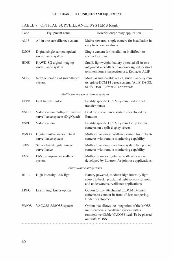
SAFEGUARDS TECHNIQUES AND EQUIPMENT
ALIS All in one surveillance system Mains powered, single camera for installation in easy to access locations
DSOS Digital single camera opticalsurveillance system
Single camera for installation in difficult to access locations
HDIS HAWK-SG digital imagingsurveillance system
Small, lightweight, battery operated all-in-one integrated surveillance camera designed for short term temporary inspection use. Replaces ALIP
NGSS Next generation of surveillancesystem
Modular and scalable optical surveillance system to replace DCM 14 based systems (ALIS, DSOS, SDIS, DMOS) from 2012 onwards
Multi-camera surveillance systems
FTPV Fuel transfer video Facility specific CCTV system used at fuel transfer ponds
VSEU Video system multiplex dual usesurveillance system (DigiQuad)
Dual use surveillance systems developed by Euratom
VSPC Video system Facility specific CCTV system for up to four cameras on a split display screen
DMOS Digital multi-camera opticalsurveillance system
Multiple camera surveillance system for up to 16 cameras with remote monitoring capability
SDIS Server based digital imagesurveillance
Multiple camera surveillance system for up to six cameras with remote monitoring capability
FAST FAST company surveillance system
Multiple camera digital surveillance system, developed by Euratom for joint use applications
Surveillance subsystems
HILL High intensity LED light Battery powered, modular high intensity light source to back up external light sources for in-air and underwater surveillance applications
LRFO Laser range finder option Option for the attachment of DCM 14 based cameras to counter in-front-of-lens tampering. Under development
TABLE 7. OPTICAL SURVEILLANCE SYSTEMS (cont.)
Code Equipment name Description/primary application
60
VMOS VACOSS-S/MOSS system Option that allows the integration of the MOSS multi-camera surveillance system with a remotely verifiable VACOSS seal. To be phased out with MOSS

CONTAINMENT AND SURVEILLANCE
4.1.1. Single camera system for easy to access locations
ALIS. The all in one surveillance (ALIS) unit (Fig. 27) is a mains operated, fully self-contained digital surveillance system based on the DCM 14 digital
WCSS Wall containment sensor system Wall penetration detection for triggering surveillance images. Under evaluation
Surveillance review systems
GARS General Advanced ReviewStation Software
For the review of ALIS, ALIP, DMOS, DSOS, GDTV, SDIS surveillance
TABLE 7. OPTICAL SURVEILLANCE SYSTEMS (cont.)
Code Equipment name Description/primary application
FIG. 27. All in one surveillance (ALIS) unit.
61
camera module. All ALIS components fit within a standard IAEA camera enclosure with all the functionality of the DCM 14 plus an integrated inspector interface terminal. Images and associated log files are stored on flashcards. With a 2 gigabyte flashcard installed, ALIS can record up to 150 000 images, depending on the compression used.
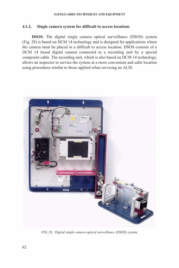
SAFEGUARDS TECHNIQUES AND EQUIPMENT
4.1.2. Single camera system for difficult to access locations
DSOS. The digital single camera optical surveillance (DSOS) system (Fig. 28) is based on DCM 14 technology and is designed for applications where the camera must be placed in a difficult to access location. DSOS consists of a DCM 14 based digital camera connected to a recording unit by a special composite cable. The recording unit, which is also based on DCM 14 technology, allows an inspector to service the system at a more convenient and safer location using procedures similar to those applied when servicing an ALIS.
62
FIG. 28. Digital single camera optical surveillance (DSOS) system.
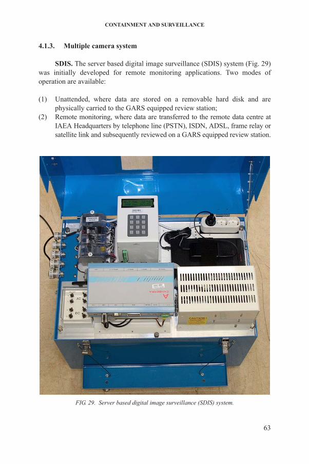
CONTAINMENT AND SURVEILLANCE
4.1.3. Multiple camera system
SDIS. The server based digital image surveillance (SDIS) system (Fig. 29) was initially developed for remote monitoring applications. Two modes of operation are available:
(1) Unattended, where data are stored on a removable hard disk and are physically carried to the GARS equipped review station;
(2) Remote monitoring, where data are transferred to the remote data centre at IAEA Headquarters by telephone line (PSTN), ISDN, ADSL, frame relay or satellite link and subsequently reviewed on a GARS equipped review station.
63
FIG. 29. Server based digital image surveillance (SDIS) system.
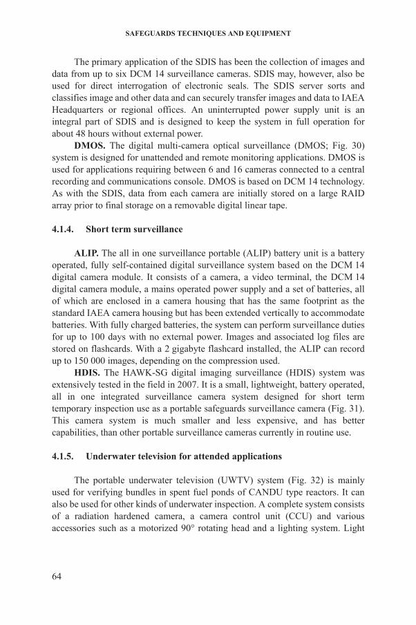
SAFEGUARDS TECHNIQUES AND EQUIPMENT
The primary application of the SDIS has been the collection of images and data from up to six DCM 14 surveillance cameras. SDIS may, however, also be used for direct interrogation of electronic seals. The SDIS server sorts and classifies image and other data and can securely transfer images and data to IAEA Headquarters or regional offices. An uninterrupted power supply unit is an integral part of SDIS and is designed to keep the system in full operation for about 48 hours without external power.
DMOS. The digital multi-camera optical surveillance (DMOS; Fig. 30) system is designed for unattended and remote monitoring applications. DMOS is used for applications requiring between 6 and 16 cameras connected to a central recording and communications console. DMOS is based on DCM 14 technology. As with the SDIS, data from each camera are initially stored on a large RAID array prior to final storage on a removable digital linear tape.
4.1.4. Short term surveillance
ALIP. The all in one surveillance portable (ALIP) battery unit is a battery operated, fully self-contained digital surveillance system based on the DCM 14digital camera module. It consists of a camera, a video terminal, the DCM 14 digital camera module, a mains operated power supply and a set of batteries, all of which are enclosed in a camera housing that has the same footprint as the standard IAEA camera housing but has been extended vertically to accommodate batteries. With fully charged batteries, the system can perform surveillance duties for up to 100 days with no external power. Images and associated log files are stored on flashcards. With a 2 gigabyte flashcard installed, the ALIP can record up to 150 000 images, depending on the compression used.
HDIS. The HAWK-SG digital imaging surveillance (HDIS) system was extensively tested in the field in 2007. It is a small, lightweight, battery operated, all in one integrated surveillance camera system designed for short term temporary inspection use as a portable safeguards surveillance camera (Fig. 31). This camera system is much smaller and less expensive, and has better capabilities, than other portable surveillance cameras currently in routine use.
4.1.5. Underwater television for attended applications
64
The portable underwater television (UWTV) system (Fig. 32) is mainly used for verifying bundles in spent fuel ponds of CANDU type reactors. It can also be used for other kinds of underwater inspection. A complete system consists of a radiation hardened camera, a camera control unit (CCU) and various accessories such as a motorized 90° rotating head and a lighting system. Light

CONTAINMENT AND SURVEILLANCE
65
FIG. 30. Digital multi-camera optical surveillance (DMOS) system.

SAFEGUARDS TECHNIQUES AND EQUIPMENT
FIG. 31. HDIS portable surveillance unit.
66
FIG. 32. Underwater television (UWTV) system.
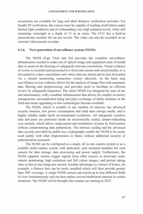
CONTAINMENT AND SURVEILLANCE
accessories are available for long and short distance verification activities. For bundle ID verification, the camera must be capable of reading small letters under limited light conditions and of withstanding very high radiation levels, while still remaining watertight at a depth of 15 m in water. The CCU has a built-in monochrome monitor for on-site review. The video can also be recorded on an external videocassette recorder.
4.1.6. Next generation of surveillance system (NGSS)
The NGSS (Figs 33(a) and (b)) provides the complete surveillance infrastructure needed to make use of optical image and equipment state of health data to assist in the drawing of safeguards relevant conclusions. Visual evidence of events is recorded and processed in a front end camera and stored locally, or is forwarded to a data consolidator unit where data are stored and in turn forwarded via a remote monitoring connection (where allowed). At the back end, surveillance review software allows for the analysis of image files with automatic data filtering and preprocessing, and provides tools to facilitate an efficient review by safeguards inspectors. The entire NGSS was designed for ease of use and maintenance, with a modular infrastructure that allows for simpler inventory management, uncomplicated (plug and play) exchange of faulty modules in the field and easier upgrading as new technologies become available.
The NGSS, which is scalable to any number of cameras, has advanced security features, low power consumption and solid state storage media, and is highly reliable under harsh environmental conditions. All safeguards sensitive data and parts are protected inside an electronically sealed, tamper-indicating core module, which allows replacement and installation of parts by third parties without compromising data authenticity. The intrinsic sealing and the advanced data security provided by public key cryptography enable the NGSS to be easily used jointly with other inspectorates or States without additional security or authentication measures.
The NGSS can be configured as a single, all in one camera system or as a scalable multi-camera system with dedicated, rack mounted modules for each camera for data storage, data processing and power supply. Furthermore, the NGSS supports various trigger signals from other sensors or electronic seals, remote monitoring, high resolution and full colour images, and picture taking
67
rates as fast as one image per second. Another advantage is a choice of lenses, for example, a fisheye lens can be easily installed which will then provide greater than 180° coverage. A single NGSS camera can record up to four different fields of view simultaneously and can thus replace several traditional cameras in certain situations. The NGSS will be brought into routine use starting in 2012.
SAFEGUARDS TECHNIQUES AND EQUIPMENT
FIG. 33(a). NGSS system with 24 cameras.
68
FIG. 33(b). Single NGSS camera.
CONTAINMENT AND SURVEILLANCE
4.1.7. High intensity LED light
Optical surveillance requires adequate light conditions to generate conclusive records, and a loss of light will ultimately render the surveillance inconclusive. The modular high intensity LED light (HILL) was developed to back up external light sources for in-air and underwater surveillance applications. The light is battery powered to allow for power failures. Unlike conventional lights, HILL is extremely reliable and does not need maintenance (such as the replacement of light bulbs) for its entire life.
4.1.8. Surveillance review software
GARS. Surveillance images are evaluated by inspectors using the sophisticated General Advanced Review Station Software (GARS). This software (Fig. 34) was developed to run on a personal computer with the appropriate media drives to review the recorded images from all DCM 14 based systems. GARS has been further developed to enable the review of surveillance records generated by the NGSS.
At its simplest, GARS provides a flexible and user friendly inspector interface (similar to popular commercial media players) for the review of images and data from flashcards, removable hard drives, CD-ROMs and digital linear tapes. GARS also has advanced features that can be used to reduce an inspector’s review effort. Those features include image and data decryption, image and data authenticity verification, scene change detection of recorded images, digital image enhancement and multiple camera display options.
4.2. CONTAINMENT (SEALS)
A sealing system always comprises a containment enclosing the nuclear material to be safeguarded, a means of applying the seal (e.g. a metal wire) and the seal itself. All three of these components must be examined in order to verify that a sealing system has fulfilled its function. Seals are tamper-indicating devices used to secure materials, documents, data signals or any other important items in tamper-indicating enclosures. When designed properly, a sealing system provides
69
evidence of any unauthorized attempt to gain access to secured material. In addition, seals also provide a means of uniquely identifying secured containers. Depending on the type of application, several seals are in use by the IAEA (as shown in Table 8). It must be pointed out, however, that these seals do not provide, nor were they designed to provide, any kind of physical protection. Since so much reliance is placed on sealing systems, all authorized systems are
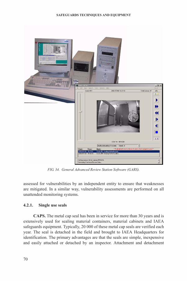
SAFEGUARDS TECHNIQUES AND EQUIPMENT
assessed for vulnerabilities by an independent entity to ensure that weaknesses are mitigated. In a similar way, vulnerability assessments are performed on all unattended monitoring systems.
4.2.1. Single use seals
FIG. 34. General Advanced Review Station Software (GARS).
70
CAPS. The metal cap seal has been in service for more than 30 years and is extensively used for sealing material containers, material cabinets and IAEA safeguards equipment. Typically, 20 000 of these metal cap seals are verified each year. The seal is detached in the field and brought to IAEA Headquarters for identification. The primary advantages are that the seals are simple, inexpensive and easily attached or detached by an inspector. Attachment and detachment
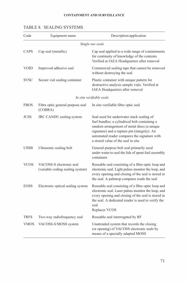
CONTAINMENT AND SURVEILLANCE
TABLE 8. SEALING SYSTEMS
Code Equipment name Description/application
Single use seals
CAPS Cap seal (metallic) Cap seal applied to a wide range of containmentsfor continuity of knowledge of the contents.Verified at IAEA Headquarters after removal
VOID Improved adhesive seal Commercial sealing tape that cannot be removedwithout destroying the seal
SVSC Secure vial sealing container Plastic container with unique pattern fordestructive analysis sample vials. Verified atIAEA Headquarters after removal
In situ verifiable seals
FBOS Fibre optic general purpose seal(COBRA)
In situ verifiable fibre optic seal
JCSS JRC CANDU sealing system Seal used for underwater stack sealing offuel bundles; a cylindrical bolt containing a random arrangement of metal discs (a uniquesignature) and a rupture pin (integrity). Anautomated reader compares the signature witha stored value of the seal in situ
USSB Ultrasonic sealing bolt General purpose bolt seal primarily usedunder water to seal the lids of spent fuel assemblycontainers
VCOS VACOSS-S electronic seal(variable coding sealing system)
Reusable seal consisting of a fibre optic loop andelectronic seal. Light pulses monitor the loop, andevery opening and closing of the seal is stored inthe seal. A palmtop computer reads the seal
EOSS Electronic optical sealing system Reusable seal consisting of a fibre optic loop andelectronic seal. Laser pulses monitor the loop, andevery opening and closing of the seal is stored inthe seal. A dedicated reader is used to verify thesealReplaces VCOS
TRFS Two-way radiofrequency seal Reusable seal interrogated by RF
71
VMOS VACOSS-S/MOSS system Unattended system that records the closing(or opening) of VACOSS electronic seals bymeans of a specially adapted MOSS
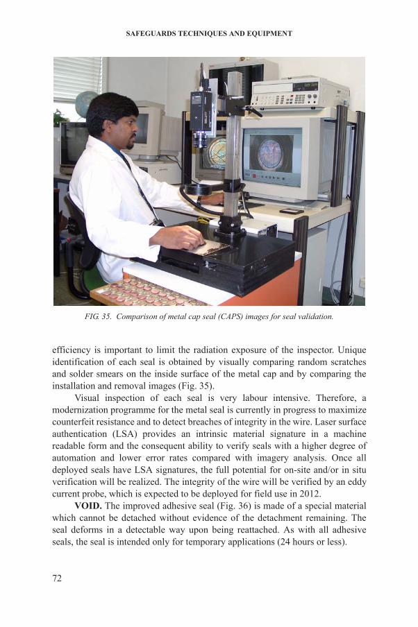
SAFEGUARDS TECHNIQUES AND EQUIPMENT
efficiency is important to limit the radiation exposure of the inspector. Unique identification of each seal is obtained by visually comparing random scratches and solder smears on the inside surface of the metal cap and by comparing the installation and removal images (Fig. 35).
Visual inspection of each seal is very labour intensive. Therefore, a modernization programme for the metal seal is currently in progress to maximize counterfeit resistance and to detect breaches of integrity in the wire. Laser surface authentication (LSA) provides an intrinsic material signature in a machine readable form and the consequent ability to verify seals with a higher degree of automation and lower error rates compared with imagery analysis. Once all deployed seals have LSA signatures, the full potential for on-site and/or in situ
FIG. 35. Comparison of metal cap seal (CAPS) images for seal validation.
72
verification will be realized. The integrity of the wire will be verified by an eddy current probe, which is expected to be deployed for field use in 2012.
VOID. The improved adhesive seal (Fig. 36) is made of a special material which cannot be detached without evidence of the detachment remaining. The seal deforms in a detectable way upon being reattached. As with all adhesive seals, the seal is intended only for temporary applications (24 hours or less).
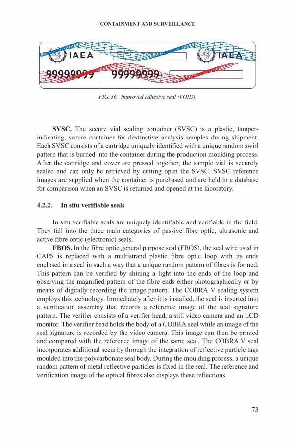
CONTAINMENT AND SURVEILLANCE
SVSC. The secure vial sealing container (SVSC) is a plastic, tamper-indicating, secure container for destructive analysis samples during shipment. Each SVSC consists of a cartridge uniquely identified with a unique random swirl pattern that is burned into the container during the production moulding process. After the cartridge and cover are pressed together, the sample vial is securely sealed and can only be retrieved by cutting open the SVSC. SVSC reference images are supplied when the container is purchased and are held in a database for comparison when an SVSC is returned and opened at the laboratory.
4.2.2. In situ verifiable seals
In situ verifiable seals are uniquely identifiable and verifiable in the field. They fall into the three main categories of passive fibre optic, ultrasonic and active fibre optic (electronic) seals.
FBOS. In the fibre optic general purpose seal (FBOS), the seal wire used in CAPS is replaced with a multistrand plastic fibre optic loop with its ends enclosed in a seal in such a way that a unique random pattern of fibres is formed. This pattern can be verified by shining a light into the ends of the loop and observing the magnified pattern of the fibre ends either photographically or by means of digitally recording the image pattern. The COBRA V sealing systememploys this technology. Immediately after it is installed, the seal is inserted into a verification assembly that records a reference image of the seal signature pattern. The verifier consists of a verifier head, a still video camera and an LCD monitor. The verifier head holds the body of a COBRA seal while an image of the seal signature is recorded by the video camera. This image can then be printed
FIG. 36. Improved adhesive seal (VOID).
73
and compared with the reference image of the same seal. The COBRA V seal incorporates additional security through the integration of reflective particle tags moulded into the polycarbonate seal body. During the moulding process, a unique random pattern of metal reflective particles is fixed in the seal. The reference and verification image of the optical fibres also displays these reflections.
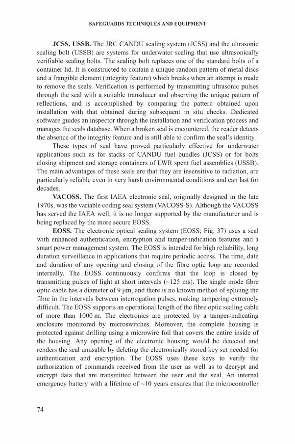
SAFEGUARDS TECHNIQUES AND EQUIPMENT
JCSS, USSB. The JRC CANDU sealing system (JCSS) and the ultrasonic sealing bolt (USSB) are systems for underwater sealing that use ultrasonically verifiable sealing bolts. The sealing bolt replaces one of the standard bolts of a container lid. It is constructed to contain a unique random pattern of metal discs and a frangible element (integrity feature) which breaks when an attempt is made to remove the seals. Verification is performed by transmitting ultrasonic pulses through the seal with a suitable transducer and observing the unique pattern of reflections, and is accomplished by comparing the pattern obtained upon installation with that obtained during subsequent in situ checks. Dedicated software guides an inspector through the installation and verification process and manages the seals database. When a broken seal is encountered, the reader detects the absence of the integrity feature and is still able to confirm the seal’s identity.
These types of seal have proved particularly effective for underwater applications such as for stacks of CANDU fuel bundles (JCSS) or for bolts closing shipment and storage containers of LWR spent fuel assemblies (USSB). The main advantages of these seals are that they are insensitive to radiation, are particularly reliable even in very harsh environmental conditions and can last for decades.
VACOSS. The first IAEA electronic seal, originally designed in the late 1970s, was the variable coding seal system (VACOSS-S). Although the VACOSS has served the IAEA well, it is no longer supported by the manufacturer and is being replaced by the more secure EOSS.
EOSS. The electronic optical sealing system (EOSS; Fig. 37) uses a seal with enhanced authentication, encryption and tamper-indication features and a smart power management system. The EOSS is intended for high reliability, long duration surveillance in applications that require periodic access. The time, date and duration of any opening and closing of the fibre optic loop are recorded internally. The EOSS continuously confirms that the loop is closed by transmitting pulses of light at short intervals (~125 ms). The single mode fibre optic cable has a diameter of 9 μm, and there is no known method of splicing the fibre in the intervals between interrogation pulses, making tampering extremely difficult. The EOSS supports an operational length of the fibre optic sealing cable of more than 1000 m. The electronics are protected by a tamper-indicating enclosure monitored by microswitches. Moreover, the complete housing is protected against drilling using a microwire foil that covers the entire inside of
74
the housing. Any opening of the electronic housing would be detected and renders the seal unusable by deleting the electronically stored key set needed for authentication and encryption. The EOSS uses these keys to verify the authorization of commands received from the user as well as to decrypt and encrypt data that are transmitted between the user and the seal. An internal emergency battery with a lifetime of ~10 years ensures that the microcontroller
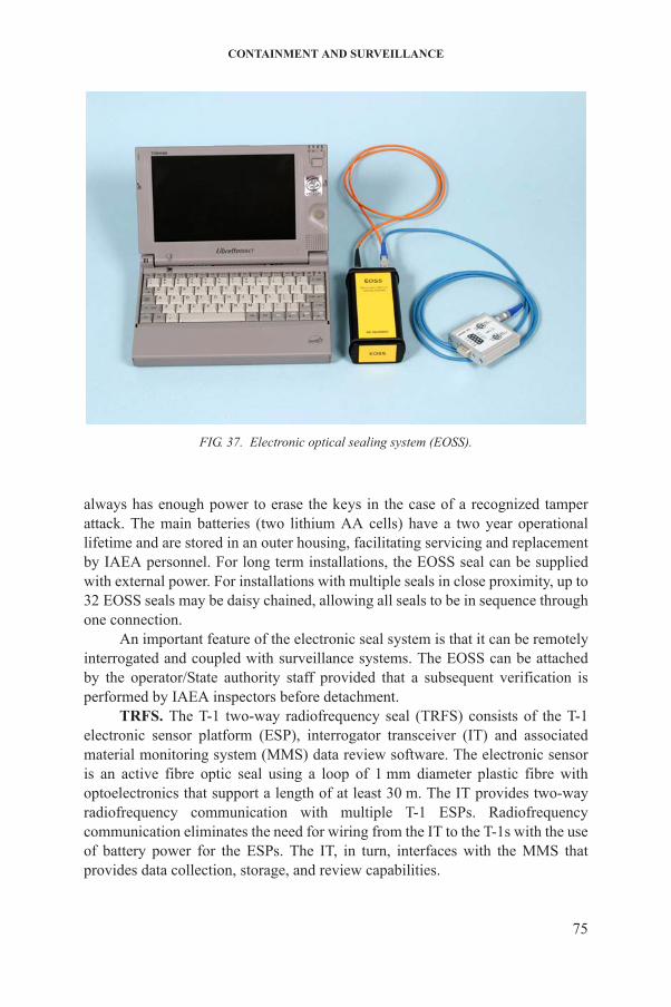
CONTAINMENT AND SURVEILLANCE
always has enough power to erase the keys in the case of a recognized tamper attack. The main batteries (two lithium AA cells) have a two year operational lifetime and are stored in an outer housing, facilitating servicing and replacement by IAEA personnel. For long term installations, the EOSS seal can be supplied with external power. For installations with multiple seals in close proximity, up to 32 EOSS seals may be daisy chained, allowing all seals to be in sequence through one connection.
An important feature of the electronic seal system is that it can be remotely interrogated and coupled with surveillance systems. The EOSS can be attached by the operator/State authority staff provided that a subsequent verification is performed by IAEA inspectors before detachment.
TRFS. The T-1 two-way radiofrequency seal (TRFS) consists of the T-1 electronic sensor platform (ESP), interrogator transceiver (IT) and associated material monitoring system (MMS) data review software. The electronic sensor
FIG. 37. Electronic optical sealing system (EOSS).
75
is an active fibre optic seal using a loop of 1 mm diameter plastic fibre with optoelectronics that support a length of at least 30 m. The IT provides two-way radiofrequency communication with multiple T-1 ESPs. Radiofrequency communication eliminates the need for wiring from the IT to the T-1s with the use of battery power for the ESPs. The IT, in turn, interfaces with the MMS that provides data collection, storage, and review capabilities.
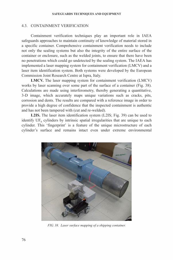
SAFEGUARDS TECHNIQUES AND EQUIPMENT
4.3. CONTAINMENT VERIFICATION
Containment verification techniques play an important role in IAEA safeguards approaches to maintain continuity of knowledge of material stored in a specific container. Comprehensive containment verification needs to include not only the sealing systems but also the integrity of the entire surface of the container or enclosure, such as the welded joints, to ensure that there have been no penetrations which could go undetected by the sealing system. The IAEA has implemented a laser mapping system for containment verification (LMCV) and a laser item identification system. Both systems were developed by the European Commission Joint Research Centre at Ispra, Italy.
LMCV. The laser mapping system for containment verification (LMCV) works by laser scanning over some part of the surface of a container (Fig. 38). Calculations are made using interferometry, thereby generating a quantitative, 3-D image, which accurately maps unique variations such as cracks, pits, corrosion and dents. The results are compared with a reference image in order to provide a high degree of confidence that the inspected containment is authentic and has not been tampered with (cut and re-welded).
L2IS. The laser item identification system (L2IS; Fig. 39) can be used to identify UF6 cylinders by intrinsic spatial irregularities that are unique to each cylinder. This ‘fingerprint’ is a feature of the unique microstructure of each cylinder’s surface and remains intact even under extreme environmental
76
FIG. 38. Laser surface mapping of a shipping container.
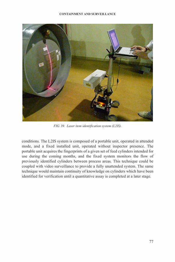
CONTAINMENT AND SURVEILLANCE
conditions. The L2IS system is composed of a portable unit, operated in attended mode, and a fixed installed unit, operated without inspector presence. The portable unit acquires the fingerprints of a given set of feed cylinders intended for use during the coming months, and the fixed system monitors the flow of previously identified cylinders between process areas. This technique could be coupled with video surveillance to provide a fully unattended system. The same technique would maintain continuity of knowledge on cylinders which have been identified for verification until a quantitative assay is completed at a later stage.
FIG. 39. Laser item identification system (L2IS).
77

5. REMOTE MONITORING SYSTEMS
The IAEA has been using remote monitoring for routine safeguards applications since 1997. Remote monitoring in the safeguards context is generally considered to mean the transmission off-site to IAEA Headquarters or to an IAEA regional office of data collected from sealing systems, unattended monitoring systems and optical surveillance systems. Safeguards approaches using remote monitoring offer the potential to reduce inspection effort while improving the timeliness of results. Cost effectiveness is a prime justification and is achieved primarily by reducing the frequency of inspection visits and shortening inspections (as the need to service sealing, surveillance and NDA equipment is reduced and in some cases eliminated). In principle, a remote monitoring system with ‘state of health’ reporting can function significantly more reliably than an unattended system that is serviced at a predetermined frequency. Some events that would ultimately lead to a failure of the system can be remotely evaluated and reported in time for appropriate action to be taken. In many instances, required corrective actions to the remote monitoring system can be handled remotely without the need to send technicians into the field. Furthermore, sealing, surveillance and NDA data can be reviewed at any time within a clean office environment. This in turn contributes to decreasing the radiation exposure of inspectors and facility personnel, and to minimizing the support required from the facility operator for IAEA inspections.
Limited IAEA human resources, the ever growing stockpile of nuclear material and other economic considerations are likely to accelerate the implementation of remote monitoring in the near future. Actual savings of inspection effort achieved through the implementation of remote monitoring are difficult to quantify accurately because such monitoring has become an integral part of many safeguards approaches and its impact on safeguards implementation cannot be viewed in isolation.
Recently, the availability of fast broadband Internet lines has allowed an expansion of the use of remote monitoring techniques (Fig. 40). In 2010, 93 unattended radiation monitoring systems and 140 surveillance systems were connected, with data routed from locations worldwide to the Remote Monitoring Data Centre (RMDC) at IAEA Headquarters. The IAEA expects a significant
78
increase in remote monitoring applications to enable it to cope with the workload anticipated in the future. It is conceivable that the number of remote monitoring systems connected to IAEA Headquarters will double within the next five years.
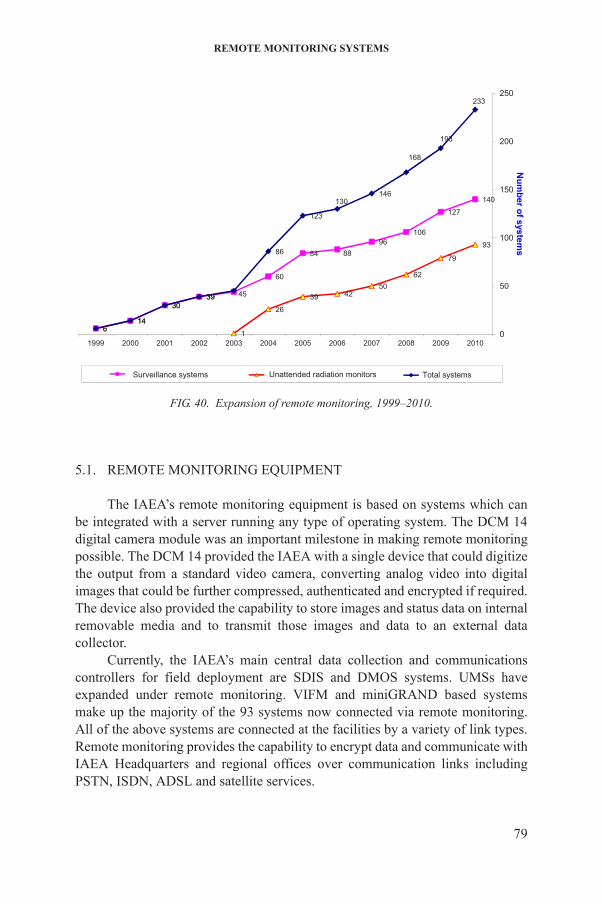
REMOTE MONITORING SYSTEMS
5.1. REMOTE MONITORING EQUIPMENT
The IAEA’s remote monitoring equipment is based on systems which can be integrated with a server running any type of operating system. The DCM 14 digital camera module was an important milestone in making remote monitoring possible. The DCM 14 provided the IAEA with a single device that could digitize the output from a standard video camera, converting analog video into digital images that could be further compressed, authenticated and encrypted if required. The device also provided the capability to store images and status data on internal removable media and to transmit those images and data to an external data collector.
Currently, the IAEA’s main central data collection and communications controllers for field deployment are SDIS and DMOS systems. UMSs have
140
127
10696
8884
60
3930
146
93
79
6250
4239
26
1
233
193
168
146130
123
86
453930
146
0
50
100
150
200
250
201020092008200720062005200420032002200120001999
Num
ber of systems
Surveillance systems Unattended radiation monitors Total systems
FIG. 40. Expansion of remote monitoring, 1999–2010.
79
expanded under remote monitoring. VIFM and miniGRAND based systems make up the majority of the 93 systems now connected via remote monitoring. All of the above systems are connected at the facilities by a variety of link types. Remote monitoring provides the capability to encrypt data and communicate with IAEA Headquarters and regional offices over communication links including PSTN, ISDN, ADSL and satellite services.

SAFEGUARDS TECHNIQUES AND EQUIPMENT
5.2. REMOTE MONITORING DATA CENTRE
In 2007, the IAEA strengthened its remote monitoring infrastructure by developing the RMDC to ensure reliable and secure transfer of safeguards data from the field to IAEA Headquarters. The RMDC is the backbone of the data transmission network and provides quality controlled field data (e.g. missing scene analysis) directly to the inspectorate at IAEA Headquarters for evaluation. It is equipped with terrestrial based communications, using the latest virtual private network (VPN) technology, and transfers data utilizing highly specialized software written in-house. ‘State of health’ data are transferred (‘pulled’) from remote systems and parsed every night, giving the IAEA near real time status of equipment operation that can be used by technicians for the immediate troubleshooting and maintenance of remote systems (Fig. 41). The data flow is permanently monitored and displayed on large plasma screens, thereby providing an instant graphical view of potential problems. Technicians can ‘drill down’ on past and present status information, including previous actions taken, to analyse a particular problem.
5.3. DATA SHARING
As a general rule, detailed safeguards information derived from IAEA equipment should not be made available to individual States. However, arrangements may be made for the sharing of certain data under cooperation arrangements with the authorities of individual States.
Remote monitoring data sharing arrangements with State and regional systems of accounting for and control of nuclear material (SSACs/RSACs) are considered carefully, requiring approval by the Deputy Director General of the
80
FIG. 41. ‘State of health’ information screen.
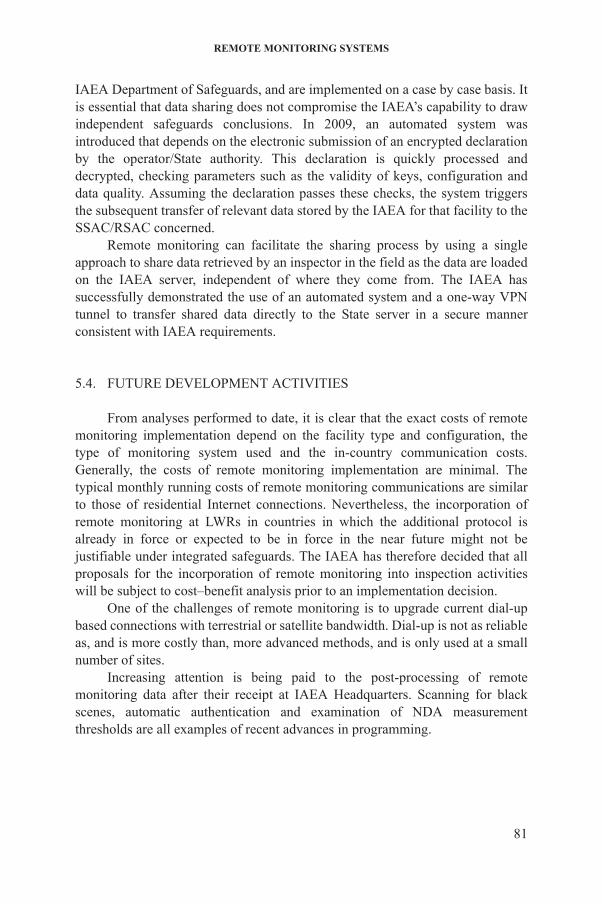
REMOTE MONITORING SYSTEMS
IAEA Department of Safeguards, and are implemented on a case by case basis. It is essential that data sharing does not compromise the IAEA’s capability to draw independent safeguards conclusions. In 2009, an automated system was introduced that depends on the electronic submission of an encrypted declaration by the operator/State authority. This declaration is quickly processed and decrypted, checking parameters such as the validity of keys, configuration and data quality. Assuming the declaration passes these checks, the system triggers the subsequent transfer of relevant data stored by the IAEA for that facility to the SSAC/RSAC concerned.
Remote monitoring can facilitate the sharing process by using a single approach to share data retrieved by an inspector in the field as the data are loaded on the IAEA server, independent of where they come from. The IAEA has successfully demonstrated the use of an automated system and a one-way VPNtunnel to transfer shared data directly to the State server in a secure manner consistent with IAEA requirements.
5.4. FUTURE DEVELOPMENT ACTIVITIES
From analyses performed to date, it is clear that the exact costs of remote monitoring implementation depend on the facility type and configuration, the type of monitoring system used and the in-country communication costs. Generally, the costs of remote monitoring implementation are minimal. The typical monthly running costs of remote monitoring communications are similar to those of residential Internet connections. Nevertheless, the incorporation of remote monitoring at LWRs in countries in which the additional protocol is already in force or expected to be in force in the near future might not be justifiable under integrated safeguards. The IAEA has therefore decided that all proposals for the incorporation of remote monitoring into inspection activities will be subject to cost–benefit analysis prior to an implementation decision.
One of the challenges of remote monitoring is to upgrade current dial-up based connections with terrestrial or satellite bandwidth. Dial-up is not as reliable as, and is more costly than, more advanced methods, and is only used at a small number of sites.
Increasing attention is being paid to the post-processing of remote
81
monitoring data after their receipt at IAEA Headquarters. Scanning for black scenes, automatic authentication and examination of NDA measurement thresholds are all examples of recent advances in programming.
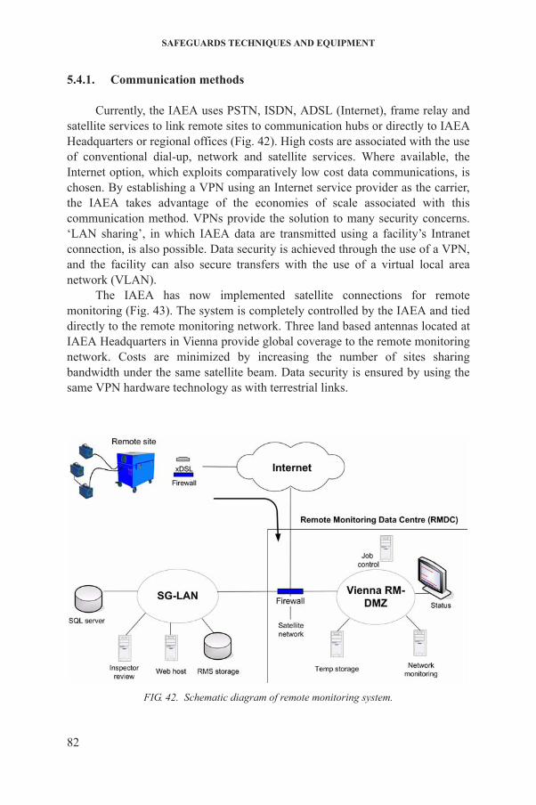
SAFEGUARDS TECHNIQUES AND EQUIPMENT
5.4.1. Communication methods
Currently, the IAEA uses PSTN, ISDN, ADSL (Internet), frame relay and satellite services to link remote sites to communication hubs or directly to IAEA Headquarters or regional offices (Fig. 42). High costs are associated with the use of conventional dial-up, network and satellite services. Where available, the Internet option, which exploits comparatively low cost data communications, is chosen. By establishing a VPN using an Internet service provider as the carrier, the IAEA takes advantage of the economies of scale associated with this communication method. VPNs provide the solution to many security concerns. ‘LAN sharing’, in which IAEA data are transmitted using a facility’s Intranet connection, is also possible. Data security is achieved through the use of a VPN, and the facility can also secure transfers with the use of a virtual local area network (VLAN).
The IAEA has now implemented satellite connections for remote monitoring (Fig. 43). The system is completely controlled by the IAEA and tied directly to the remote monitoring network. Three land based antennas located at IAEA Headquarters in Vienna provide global coverage to the remote monitoring network. Costs are minimized by increasing the number of sites sharing bandwidth under the same satellite beam. Data security is ensured by using the same VPN hardware technology as with terrestrial links.
82
FIG. 42. Schematic diagram of remote monitoring system.
REMOTE MONITORING SYSTEMS
5.4.2. Facility integration
In various facilities, a number of stand-alone safeguards systems are distributed in different areas and individually require routine service by inspectors. To facilitate safeguards data collection, such systems are increasingly networked and their data accumulated at central collection stations. Wireless communications within a facility can reduce costly cabling jobs and have been proven not to interfere with facility operations (Fig. 44). General Packet Radio Service (GPRS) and 3G or universal mobile telecommunications system (UMTS) wireless data services have also been tested and implemented to provide Internet connectivity at some sites. Again, data security is provided by standard VPN hardware.
FIG. 43. Satellite antenna at IAEA Headquarters.
83
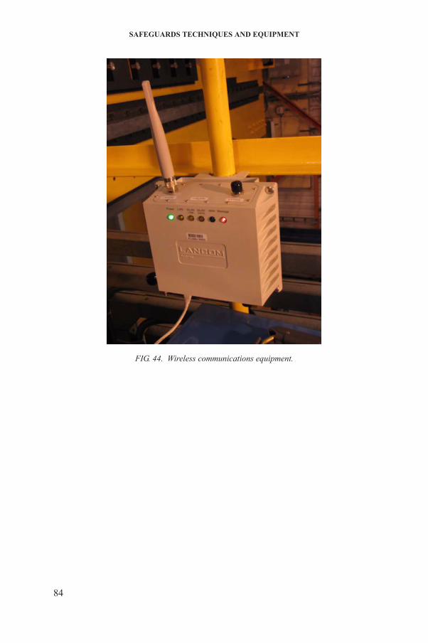
SAFEGUARDS TECHNIQUES AND EQUIPMENT
FIG. 44. Wireless communications equipment.
84
6. DESTRUCTIVE ANALYSIS
Destructive analysis measurements for element assay and determination of isotopic composition can be made of all types of solid and liquid materials encountered in bulk handling nuclear plants. Destructive analysis is used in the following ways:
(a) To verify that protracted diversion of safeguarded nuclear materials has not occurred;
(b) To certify working standards used for the calibration of NDA and installed verification instruments;
(c) To provide assurance of the quality and independence of on-site measurements (e.g. validation of facility specific procedures);
(d) To carry out periodic verification of operator measurement systems.
Destructive analysis verification measurements involve the following steps:
(1) Taking of independent samples;(2) Conditioning of these samples at the facility to ensure that they maintain
their chemical form and their integrity during transport;(3) Packaging, sealing and shipment of samples to the IAEA Nuclear Material
Laboratory (NML) at the Safeguards Analytical Laboratory (SAL) in Seibersdorf, Austria;
(4) Analysis of samples at the NML or through the Network of Analytical Laboratories (NWAL) (laboratories in different States that have been qualified to analyse safeguards samples);
(5) Statistical evaluation of analysis results.
To obtain meaningful and sufficiently accurate results, it is necessary to apply optimized and validated procedures for each of these steps. It is of the utmost importance to take a representative sample of the item and to properly conserve this sample during its handling at the plant and shipment to the analytical laboratory.
Bulk measurement is generally considered to be part of sampling. The
85
sample related bulk data collected on-site by the inspector concomitantly with the sampling includes the weights or volumes of the sampled items or batches as declared by the operator and verified by the inspector. In addition to the bulk data, the operator’s declarations with respect to the elemental and isotopic composition of the materials sampled are recorded in a working paper. This working paper provides instructions regarding the sample amounts to be taken and the most
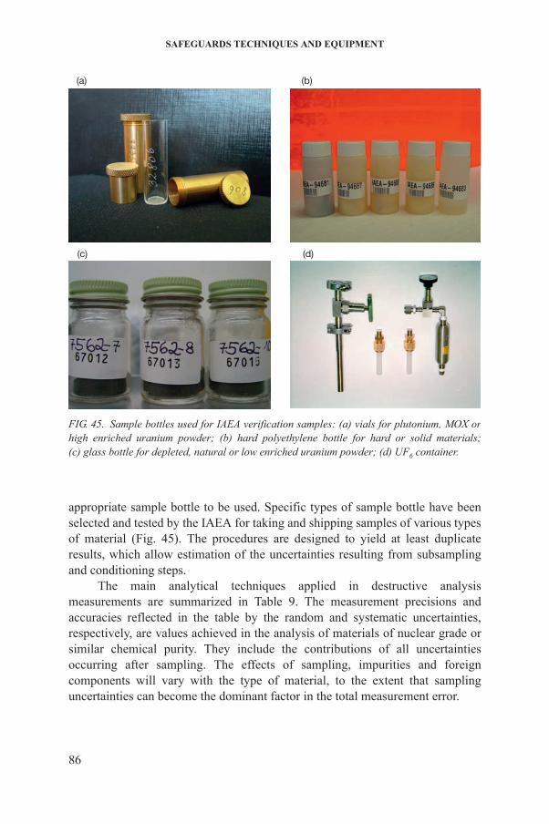
SAFEGUARDS TECHNIQUES AND EQUIPMENT
appropriate sample bottle to be used. Specific types of sample bottle have been selected and tested by the IAEA for taking and shipping samples of various types of material (Fig. 45). The procedures are designed to yield at least duplicate results, which allow estimation of the uncertainties resulting from subsampling and conditioning steps.
The main analytical techniques applied in destructive analysis measurements are summarized in Table 9. The measurement precisions and accuracies reflected in the table by the random and systematic uncertainties,
(a) (b)
(c) (d)
FIG. 45. Sample bottles used for IAEA verification samples: (a) vials for plutonium, MOX or high enriched uranium powder; (b) hard polyethylene bottle for hard or solid materials; (c) glass bottle for depleted, natural or low enriched uranium powder; (d) UF6 container.
86
respectively, are values achieved in the analysis of materials of nuclear grade or similar chemical purity. They include the contributions of all uncertainties occurring after sampling. The effects of sampling, impurities and foreign components will vary with the type of material, to the extent that sampling uncertainties can become the dominant factor in the total measurement error.
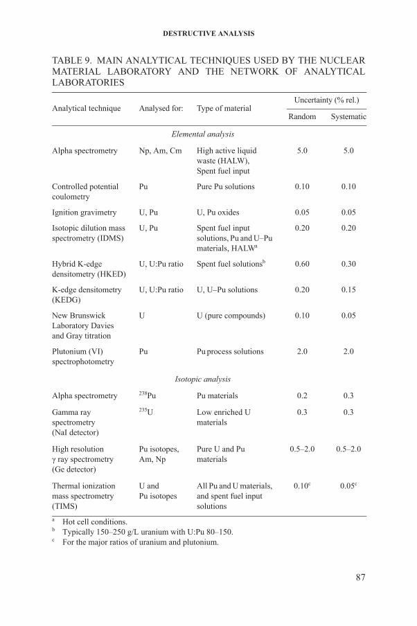
DESTRUCTIVE ANALYSIS
TABLE 9. MAIN ANALYTICAL TECHNIQUES USED BY THE NUCLEAR MATERIAL LABORATORY AND THE NETWORK OF ANALYTICAL LABORATORIES
Analytical technique Analysed for: Type of materialUncertainty (% rel.)
Random Systematic
Elemental analysis
Alpha spectrometry Np, Am, Cm High active liquid waste (HALW),Spent fuel input
5.0 5.0
Controlled potentialcoulometry
Pu Pure Pu solutions 0.10 0.10
Ignition gravimetry U, Pu U, Pu oxides 0.05 0.05
Isotopic dilution massspectrometry (IDMS)
U, Pu Spent fuel input solutions, Pu and U–Pu materials, HALWa
0.20 0.20
Hybrid K-edgedensitometry (HKED)
U, U:Pu ratio Spent fuel solutionsb 0.60 0.30
K-edge densitometry(KEDG)
U, U:Pu ratio U, U–Pu solutions 0.20 0.15
New BrunswickLaboratory Daviesand Gray titration
U U (pure compounds) 0.10 0.05
Plutonium (VI)spectrophotometry
Pu Pu process solutions 2.0 2.0
Isotopic analysis
Alpha spectrometry 238Pu Pu materials 0.2 0.3
Gamma rayspectrometry(NaI detector)
235U Low enriched U materials
0.3 0.3
High resolutionγ ray spectrometry(Ge detector)
Pu isotopes,Am, Np
Pure U and Pu materials
0.5–2.0 0.5–2.0
87
Thermal ionizationmass spectrometry(TIMS)
U andPu isotopes
All Pu and U materials, and spent fuel input solutions
0.10c 0.05c
a Hot cell conditions.b Typically 150–250 g/L uranium with U:Pu 80–150.c For the major ratios of uranium and plutonium.

SAFEGUARDS TECHNIQUES AND EQUIPMENT
The accountability measurements of the facility operators and the verification measurements by the inspectors are expected to meet internationally accepted standards of precision and accuracy, defined by an international panel of analytical chemists and data evaluation specialists, and reviewed at regular intervals.
6.1. ELEMENTAL ANALYSIS
6.1.1. Uranium analysis by potentiometric titration
New Brunswick Laboratory (NBL) Davies and Gray titration is the basic method for the determination of uranium content in gram size samples of all types of non-irradiated material. An automated titration system, developed at SAL, achieves measurement precisions and relative accuracies of 0.05% or better in routine operation. This method is applicable to samples of any uranium material containing at least 50 mg of uranium (so that at least four replicate aliquots of the sample, containing at least 10 mg of uranium each, can be titrated).
6.1.2. Plutonium analysis by controlled potential coulometry
Controlled potential coulometry (Fig. 46) is used to determine 4–10 mg quantities of plutonium. Coulometry can also be used to determine plutonium in samples of industrial materials, provided that chemical separation is first carried out to remove potentially interfering elements. The technique can be applied to gram size plutonium samples, such as plutonium product solutions, plutonium metal and plutonium oxide powders or pellets, and to mixed uranium and plutonium oxides after dissolution of the solid sample.
6.1.3. Uranium or plutonium analysis by isotope dilution mass spectrometry
Isotope dilution mass spectrometry (IDMS) is the basic technique for safeguards verification measurements of uranium or plutonium in all samples of spent fuel input solutions, but also for samples of low content, such as milligram
88
size uranium–plutonium samples and wastes, or for sample types where titration, coulometry, ignition gravimetry or other destructive analysis methods are unsuitable.
The determination of uranium and/or plutonium in high burnup spent fuel input solutions involves taking a representative sample from the input
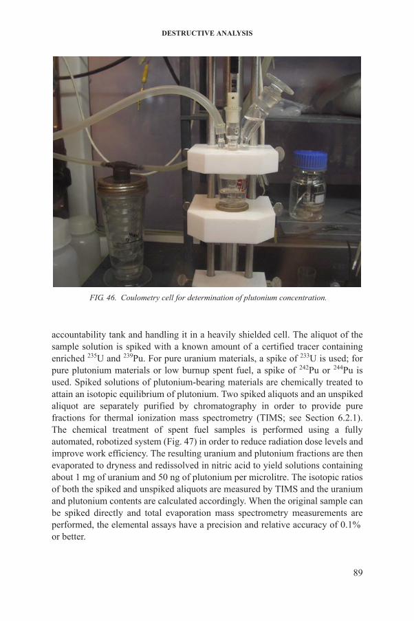
DESTRUCTIVE ANALYSIS
accountability tank and handling it in a heavily shielded cell. The aliquot of the sample solution is spiked with a known amount of a certified tracer containing enriched 235U and 239Pu. For pure uranium materials, a spike of 233U is used; for pure plutonium materials or low burnup spent fuel, a spike of 242Pu or 244Pu is used. Spiked solutions of plutonium-bearing materials are chemically treated to attain an isotopic equilibrium of plutonium. Two spiked aliquots and an unspiked aliquot are separately purified by chromatography in order to provide pure fractions for thermal ionization mass spectrometry (TIMS; see Section 6.2.1). The chemical treatment of spent fuel samples is performed using a fully automated, robotized system (Fig. 47) in order to reduce radiation dose levels and improve work efficiency. The resulting uranium and plutonium fractions are then evaporated to dryness and redissolved in nitric acid to yield solutions containing
FIG. 46. Coulometry cell for determination of plutonium concentration.
89
about 1 mg of uranium and 50 ng of plutonium per microlitre. The isotopic ratios of both the spiked and unspiked aliquots are measured by TIMS and the uranium and plutonium contents are calculated accordingly. When the original sample can be spiked directly and total evaporation mass spectrometry measurements are performed, the elemental assays have a precision and relative accuracy of 0.1% or better.

SAFEGUARDS TECHNIQUES AND EQUIPMENT
6.1.4. Uranium analysis by ignition gravimetry
Ignition gravimetry is a reliable and accurate analytical method for elemental assay, especially if gram size samples are available. It is applied for determining uranium concentrations in nuclear grade uranium and plutonium oxides. An accurately weighed sample is converted to stoichiometric U3O8 by ignition in air to a constant mass at 900 ± 10°C for uranium.
The amount of uranium or plutonium in the sample is calculated using a gravimetric conversion factor for U3O8 to uranium that depends on the isotopic composition of the sample. The precision and relative accuracy for nuclear grade oxides containing less than 200 ppm of impurities are of the order of 0.05% or better.
FIG. 47. Robotized system for separation of spent fuel input solution samples.
90
The presence of non-volatile impurities (the more frequent and abundant being iron, silicon, aluminium and calcium) requires a correction, based on the impurity content determined by XRF spectrometry and/or inductively coupled plasma–mass spectrometry.

DESTRUCTIVE ANALYSIS
6.1.5. Uranium, thorium and plutonium analysis by K-edge densitometry
K-edge densitometry (KEDG) and hybrid K-edge densitometry (HKED) are radiometric techniques applicable to all uranium, thorium and plutonium materials and to mixed uranium–thorium or uranium–plutonium samples containing a sufficient amount of the analyte (Fig. 48). A precision and relative accuracy of about 0.2% may be achieved in analytes with a concentration of 50–150 g/L. The techniques are very selective and rapid, as samples do not require dilution or any other treatment prior to measurement.
KEDG and HKED systems are installed primarily in on-site analytical laboratories associated with reprocessing plants.
6.1.6. Plutonium analysis by K X ray fluorescence analysis
K X ray fluorescence analysis is applied to samples of PuO2 and plutonium nitrate solutions containing at least 3–4 mg of plutonium with the addition of known amounts of uranium as an internal standard. It is also used for uranium
91
FIG. 48. Uranium/plutonium analysis by hybrid K-edge X ray densitometry (HKED).
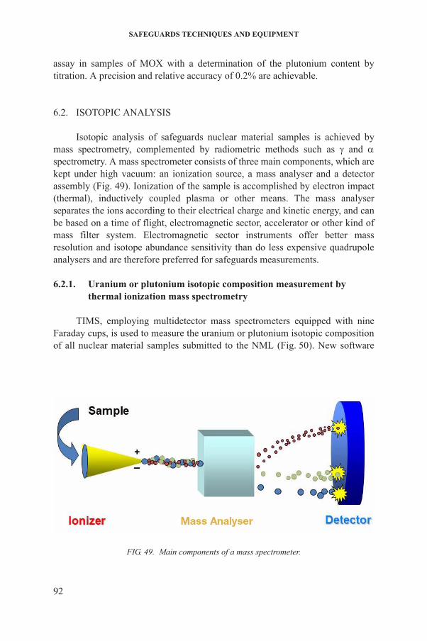
SAFEGUARDS TECHNIQUES AND EQUIPMENT
assay in samples of MOX with a determination of the plutonium content by titration. A precision and relative accuracy of 0.2% are achievable.
6.2. ISOTOPIC ANALYSIS
Isotopic analysis of safeguards nuclear material samples is achieved by mass spectrometry, complemented by radiometric methods such as and spectrometry. A mass spectrometer consists of three main components, which are kept under high vacuum: an ionization source, a mass analyser and a detector assembly (Fig. 49). Ionization of the sample is accomplished by electron impact (thermal), inductively coupled plasma or other means. The mass analyser separates the ions according to their electrical charge and kinetic energy, and can be based on a time of flight, electromagnetic sector, accelerator or other kind of mass filter system. Electromagnetic sector instruments offer better mass resolution and isotope abundance sensitivity than do less expensive quadrupole analysers and are therefore preferred for safeguards measurements.
6.2.1. Uranium or plutonium isotopic composition measurement by thermal ionization mass spectrometry
TIMS, employing multidetector mass spectrometers equipped with nine Faraday cups, is used to measure the uranium or plutonium isotopic composition of all nuclear material samples submitted to the NML (Fig. 50). New software
92
FIG. 49. Main components of a mass spectrometer.
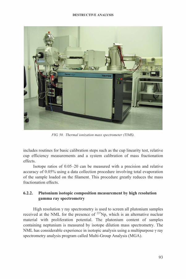
DESTRUCTIVE ANALYSIS
includes routines for basic calibration steps such as the cup linearity test, relative cup efficiency measurements and a system calibration of mass fractionation effects.
Isotope ratios of 0.05–20 can be measured with a precision and relative accuracy of 0.05% using a data collection procedure involving total evaporation of the sample loaded on the filament. This procedure greatly reduces the mass fractionation effects.
6.2.2. Plutonium isotopic composition measurement by high resolution gamma ray spectrometry
High resolution γ ray spectrometry is used to screen all plutonium samples 237
FIG. 50. Thermal ionization mass spectrometer (TIMS).
93
received at the NML for the presence of Np, which is an alternative nuclear material with proliferation potential. The plutonium content of samples containing neptunium is measured by isotope dilution mass spectrometry. The NML has considerable experience in isotopic analysis using a multipurpose γ ray spectrometry analysis program called Multi-Group Analysis (MGA).
SAFEGUARDS TECHNIQUES AND EQUIPMENT
Samples containing plutonium are placed, in their original packaging, on a planar germanium detector and a spectrum is acquired in the energy range of 0–614 keV. The spectrum is then analysed using MGA, which calculates the abundances of 238Pu, 239Pu, 240Pu and 241Pu. The isotope 242Pu is estimated from isotopic correlation. The abundances of 235U and 237Np, if present in the plutonium sample, as well as that of 241Am, are determined simultaneously. Typical precisions and accuracies range between 0.5 and 2% for all isotope abundances except 242Pu.
6.2.3. Alpha spectrometry
Alpha spectrometry is used in parallel with thermal ionization mass spectrometry for the determination of 238Pu abundance or for the measurement of plutonium in spent fuel samples; Si(Li) or ion implanted detectors are utilized for these measurements. Neptunium-237 and 244Cm are also measured by spectrometry in combination with chemical separations.
6.3. OTHER DESTRUCTIVE ANALYSIS TECHNIQUES
A variety of other techniques are used to provide additional information about nuclear material samples, or are used for samples where the above methods are not appropriate.
6.3.1. Inductively coupled plasma mass spectrometry
Inductively coupled plasma mass spectrometry (ICP-MS) is capable of determining most elements at the parts per billion level. ICP-MS is used mainly for the determination of impurities in various matrices such as uranium ore concentrate. This is useful for determining if nuclear material is of a composition and purity suitable for fuel fabrication or for being isotopically enriched (this is the point of the fuel cycle at which detailed safeguards procedures begin), or for confirming a declared change in a facility’s operations. The ICP-MS used in the NML is a magnetic sector double-focusing mass spectrometer with a single ion counting detector system and peak-jumping data collection. Precision and
94
relative accuracy for most impurity elements are in the range of 5–20%.
6.3.2. Spectrophotometric determination of hexavalent plutonium
Plutonium(VI) spectrophotometry is used to determine milligram amounts of plutonium in small samples of plutonium product samples, with a total
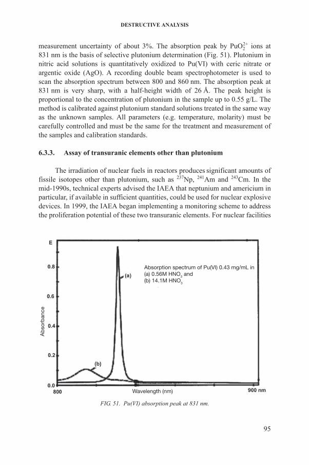
DESTRUCTIVE ANALYSIS
measurement uncertainty of about 3%. The absorption peak by PuO22+ ions at
831 nm is the basis of selective plutonium determination (Fig. 51). Plutonium in nitric acid solutions is quantitatively oxidized to Pu(VI) with ceric nitrate or argentic oxide (AgO). A recording double beam spectrophotometer is used to scan the absorption spectrum between 800 and 860 nm. The absorption peak at 831 nm is very sharp, with a half-height width of 26 Å. The peak height is proportional to the concentration of plutonium in the sample up to 0.55 g/L. The method is calibrated against plutonium standard solutions treated in the same way as the unknown samples. All parameters (e.g. temperature, molarity) must be carefully controlled and must be the same for the treatment and measurement of the samples and calibration standards.
6.3.3. Assay of transuranic elements other than plutonium
The irradiation of nuclear fuels in reactors produces significant amounts of fissile isotopes other than plutonium, such as 237Np, 241Am and 243Cm. In the mid-1990s, technical experts advised the IAEA that neptunium and americium in particular, if available in sufficient quantities, could be used for nuclear explosive devices. In 1999, the IAEA began implementing a monitoring scheme to address the proliferation potential of these two transuranic elements. For nuclear facilities
Absorption spectrum of Pu(VI) 0.43 mg/mL in(a) 0.56M HNO3 and(b) 14.1M HNO3
Ab
sorb
ance
95
Wavelength (nm)
FIG. 51. Pu(VI) absorption peak at 831 nm.
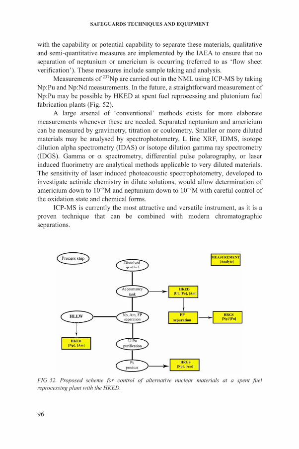
SAFEGUARDS TECHNIQUES AND EQUIPMENT
with the capability or potential capability to separate these materials, qualitative and semi-quantitative measures are implemented by the IAEA to ensure that no separation of neptunium or americium is occurring (referred to as ‘flow sheet verification’). These measures include sample taking and analysis.
Measurements of 237Np are carried out in the NML using ICP-MS by taking Np:Pu and Np:Nd measurements. In the future, a straightforward measurement of Np:Pu may be possible by HKED at spent fuel reprocessing and plutonium fuel fabrication plants (Fig. 52).
A large arsenal of ‘conventional’ methods exists for more elaborate measurements whenever these are needed. Separated neptunium and americium can be measured by gravimetry, titration or coulometry. Smaller or more diluted materials may be analysed by spectrophotometry, L line XRF, IDMS, isotope dilution alpha spectrometry (IDAS) or isotope dilution gamma ray spectrometry (IDGS). Gamma or spectrometry, differential pulse polarography, or laser induced fluorimetry are analytical methods applicable to very diluted materials. The sensitivity of laser induced photoacoustic spectrophotometry, developed to investigate actinide chemistry in dilute solutions, would allow determination of americium down to 10–8M and neptunium down to 10–7M with careful control of the oxidation state and chemical forms.
ICP-MS is currently the most attractive and versatile instrument, as it is a proven technique that can be combined with modern chromatographic separations.
96
FIG. 52. Proposed scheme for control of alternative nuclear materials at a spent fuel reprocessing plant with the HKED.
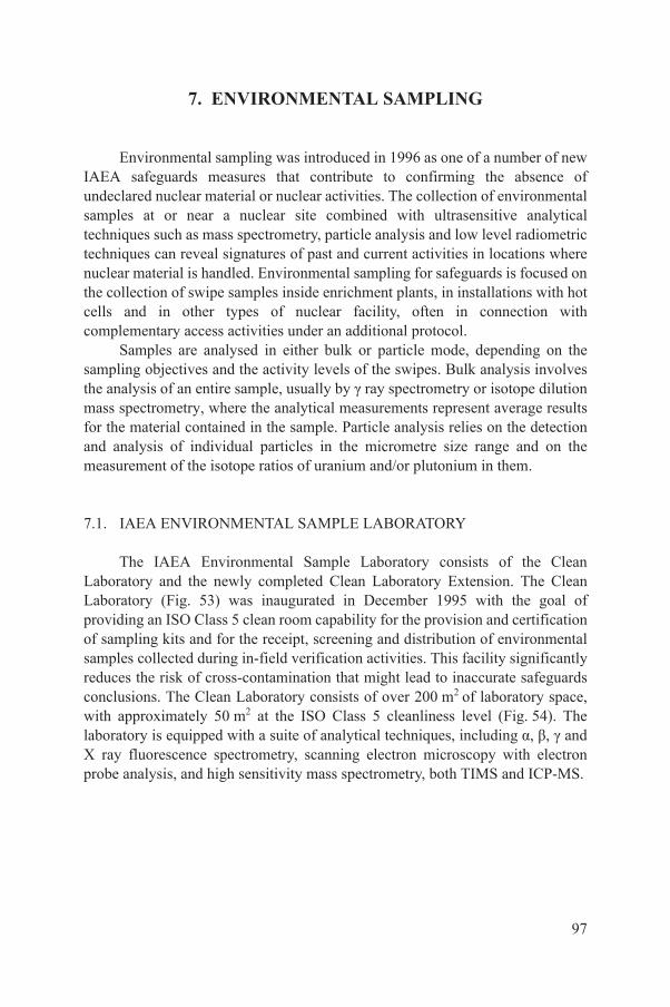
7. ENVIRONMENTAL SAMPLING
Environmental sampling was introduced in 1996 as one of a number of new IAEA safeguards measures that contribute to confirming the absence of undeclared nuclear material or nuclear activities. The collection of environmental samples at or near a nuclear site combined with ultrasensitive analytical techniques such as mass spectrometry, particle analysis and low level radiometric techniques can reveal signatures of past and current activities in locations where nuclear material is handled. Environmental sampling for safeguards is focused on the collection of swipe samples inside enrichment plants, in installations with hot cells and in other types of nuclear facility, often in connection with complementary access activities under an additional protocol.
Samples are analysed in either bulk or particle mode, depending on the sampling objectives and the activity levels of the swipes. Bulk analysis involves the analysis of an entire sample, usually by γ ray spectrometry or isotope dilution mass spectrometry, where the analytical measurements represent average results for the material contained in the sample. Particle analysis relies on the detection and analysis of individual particles in the micrometre size range and on the measurement of the isotope ratios of uranium and/or plutonium in them.
7.1. IAEA ENVIRONMENTAL SAMPLE LABORATORY
The IAEA Environmental Sample Laboratory consists of the Clean Laboratory and the newly completed Clean Laboratory Extension. The Clean Laboratory (Fig. 53) was inaugurated in December 1995 with the goal of providing an ISO Class 5 clean room capability for the provision and certification of sampling kits and for the receipt, screening and distribution of environmental samples collected during in-field verification activities. This facility significantly reduces the risk of cross-contamination that might lead to inaccurate safeguards conclusions. The Clean Laboratory consists of over 200 m2 of laboratory space, with approximately 50 m2 at the ISO Class 5 cleanliness level (Fig. 54). The laboratory is equipped with a suite of analytical techniques, including α, β, γ and X ray fluorescence spectrometry, scanning electron microscopy with electron
97
probe analysis, and high sensitivity mass spectrometry, both TIMS and ICP-MS.
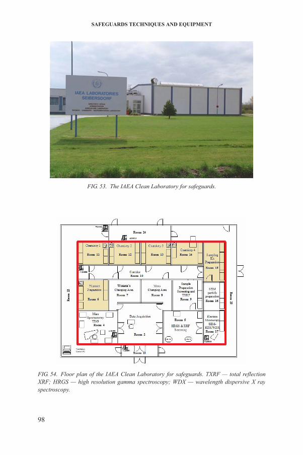
SAFEGUARDS TECHNIQUES AND EQUIPMENT
FIG. 53. The IAEA Clean Laboratory for safeguards.
98
FIG. 54. Floor plan of the IAEA Clean Laboratory for safeguards. TXRF — total reflection XRF; HRGS — high resolution gamma spectroscopy; WDX — wavelength dispersive X ray spectroscopy.
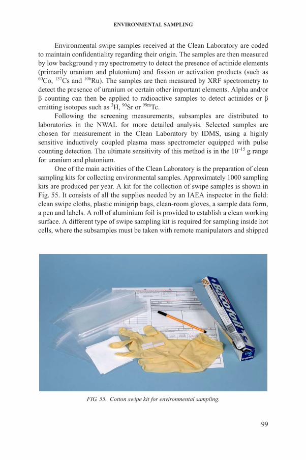
ENVIRONMENTAL SAMPLING
Environmental swipe samples received at the Clean Laboratory are coded to maintain confidentiality regarding their origin. The samples are then measured by low background γ ray spectrometry to detect the presence of actinide elements (primarily uranium and plutonium) and fission or activation products (such as 60Co, 137Cs and 106Ru). The samples are then measured by XRF spectrometry to detect the presence of uranium or certain other important elements. Alpha and/or β counting can then be applied to radioactive samples to detect actinides or β emitting isotopes such as 3H, 90Sr or 99mTc.
Following the screening measurements, subsamples are distributed to laboratories in the NWAL for more detailed analysis. Selected samples are chosen for measurement in the Clean Laboratory by IDMS, using a highly sensitive inductively coupled plasma mass spectrometer equipped with pulse counting detection. The ultimate sensitivity of this method is in the 10–15 g range for uranium and plutonium.
One of the main activities of the Clean Laboratory is the preparation of clean sampling kits for collecting environmental samples. Approximately 1000 samplingkits are produced per year. A kit for the collection of swipe samples is shown in Fig. 55. It consists of all the supplies needed by an IAEA inspector in the field: clean swipe cloths, plastic minigrip bags, clean-room gloves, a sample data form, a pen and labels. A roll of aluminium foil is provided to establish a clean working surface. A different type of swipe sampling kit is required for sampling inside hot cells, where the subsamples must be taken with remote manipulators and shipped
99
FIG. 55. Cotton swipe kit for environmental sampling.
SAFEGUARDS TECHNIQUES AND EQUIPMENT
back to the IAEA in a special shielded container because of their higher radiation level.
7.2. SCREENING OF SAMPLES
Screening of all incoming environmental samples is performed to obtain information to guide further detailed analysis, and to assist in the shipment of samples to the NWAL. Samples that are known to be above the radioactivity limits established for shipment from the field to the IAEA are delivered directly to the nuclear laboratory of the NML for screening and archival storage, because the Clean Laboratory is not licensed to handle such materials. All samples known to be below the limits for radioactive shipment are delivered to the Clean Laboratory, where they are screened, archived, analysed and/or transferred to the NWAL.
7.2.1. Low level gamma ray spectrometry
Immediately after receipt, environmental samples are measured with a low background γ ray spectrometer system. The spectrometer is based on a 90% efficient coaxial germanium detector enclosed in a high purity lead shield of 10 cm thickness. The samples, in special beakers, are placed in a 15 position sample changer and counted for one hour each to provide a γ ray spectrum in the energy range from 5 keV to 3 MeV. The total γ activity, corrected for background, is obtained by this method; if sufficient activity is detected, an evaluation of the spectral peaks can be performed to estimate the activity in the sample of individual γ emitting isotopes such as 60Co, 95Zr, 106Ru, 134Cs, 137Cs and 241Am. The nuclides of interest, their half-lives and their main γ ray energies are shown in Table 10. Depending on the number of counts collected, the precision and relative accuracy of these measurements are in the range of 2–5%. The absolute activity of individual radioisotopes is not as important as their relative activity compared with a selected isotope such as 137Cs.
7.2.2. X ray fluorescence spectrometry
100
In addition to the HRGS screening, XRF screening is performed on all ‘cold’ samples in the Clean Laboratory to detect nanogram to milligram amounts of uranium or other elements of interest on the surface of the swipes. The sample is held by a robot arm and irradiated with X rays from an X ray tube, resulting in the emission of fluorescent X rays from elements present on the swipe. These fluorescent X rays are detected using a 100 mm2 Si(Li) detector placed near the
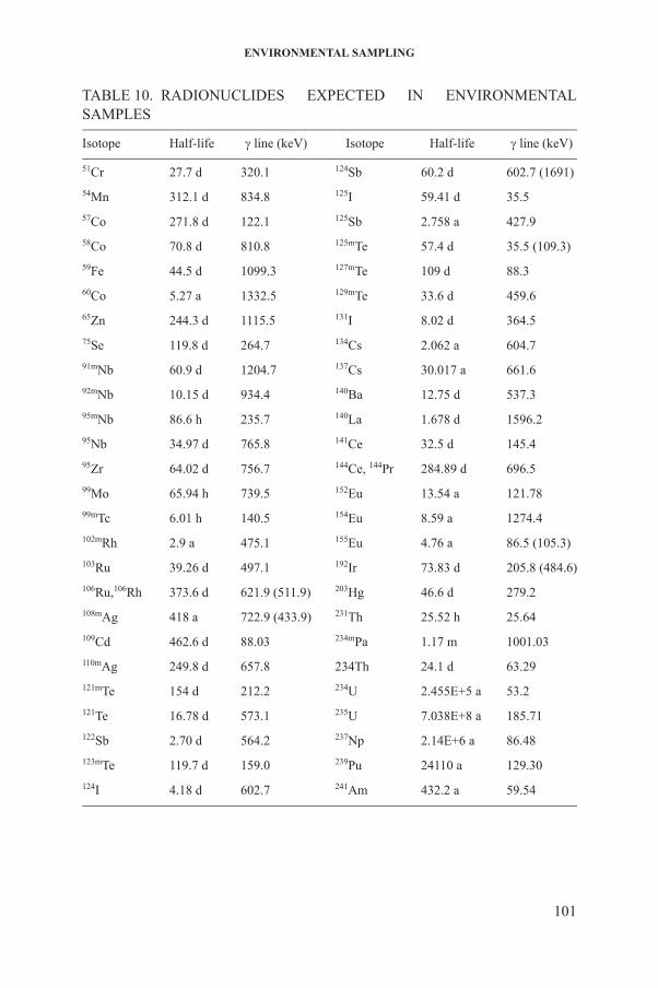
ENVIRONMENTAL SAMPLING
TABLE 10. RADIONUCLIDES EXPECTED IN ENVIRONMENTAL SAMPLES
Isotope Half-life line (keV) Isotope Half-life line (keV)
51Cr 27.7 d 320.1 124Sb 60.2 d 602.7 (1691)
54Mn 312.1 d 834.8 125I 59.41 d 35.5
57Co 271.8 d 122.1 125Sb 2.758 a 427.9
58Co 70.8 d 810.8 125mTe 57.4 d 35.5 (109.3)
59Fe 44.5 d 1099.3 127mTe 109 d 88.3
60Co 5.27 a 1332.5 129mTe 33.6 d 459.6
65Zn 244.3 d 1115.5 131I 8.02 d 364.5
75Se 119.8 d 264.7 134Cs 2.062 a 604.7
91mNb 60.9 d 1204.7 137Cs 30.017 a 661.6
92mNb 10.15 d 934.4 140Ba 12.75 d 537.3
95mNb 86.6 h 235.7 140La 1.678 d 1596.2
95Nb 34.97 d 765.8 141Ce 32.5 d 145.4
95Zr 64.02 d 756.7 144Ce, 144Pr 284.89 d 696.5
99Mo 65.94 h 739.5 152Eu 13.54 a 121.78
99mTc 6.01 h 140.5 154Eu 8.59 a 1274.4
102mRh 2.9 a 475.1 155Eu 4.76 a 86.5 (105.3)
103Ru 39.26 d 497.1 192Ir 73.83 d 205.8 (484.6)
106Ru,106Rh 373.6 d 621.9 (511.9) 203Hg 46.6 d 279.2
108mAg 418 a 722.9 (433.9) 231Th 25.52 h 25.64
109Cd 462.6 d 88.03 234mPa 1.17 m 1001.03
110mAg 249.8 d 657.8 234Th 24.1 d 63.29
121mTe 154 d 212.2 234U 2.455E+5 a 53.2
121Te 16.78 d 573.1 235U 7.038E+8 a 185.71
122Sb 2.70 d 564.2 237Np 2.14E+6 a 86.48
101
123mTe 119.7 d 159.0 239Pu 24110 a 129.30
124I 4.18 d 602.7 241Am 432.2 a 59.54
SAFEGUARDS TECHNIQUES AND EQUIPMENT
sample. Counting is performed for 4–5 hours and the spectra are then evaluated to determine the amount of the element present as well as its spatial distribution. This system has a detection capability of approximately 35 ng/cm2 for uranium within a four hour measurement time. The screening method is completely non-invasive because the subsample can be measured inside its plastic bagging.
7.2.3. Alpha/beta counting
A gridded ionization chamber counting system can be used to screen radioactive swipe samples for the presence of α or β emitting isotopes. The swipes are subsampled with an adhesive carbon disc, which is placed in the counting chamber and measured for one hour.
This system has high collection efficiency and a sensitivity in the millibecquerel range. Alpha emitting nuclides (such as 210Po) and β emitters (such as 3H, 90Sr and 99mTc) can be measured with much more sensitivity in this way than by γ or X ray methods.
7.3. BULK ANALYSIS
The bulk analysis of environmental swipe samples starts with burning the swipe matrix (either cotton or cellulose) in a furnace at 600oC for a period of four hours. The resulting ash is dissolved in ultra-high purity nitric acid, with the addition of small amounts of hydrogen fluoride. An archive portion of this ‘mother solution’ is retained and the remainder is split between spiked and unspiked portions. The spikes used are 233U and 242Pu provided by the Institute for Reference Materials and Measurements (IRMM) in Geel, Belgium. All fractions are subjected to a multi-step ion exchange separation procedure to remove matrix and interfering elements and to arrive at a pure fraction of uranium or plutonium. Appropriate dilutions are prepared from these fractions and the final measurements are performed with ICP-MS (Fig. 56). Because of the need for the highest accuracy uranium isotope ratios, these measurements are performed with TIMS using drop deposition on a rhenium filament. The relative accuracy and precision of the IDMS measurements by ICP-MS are in the range of 5–10% and the isotopic measurements by ICP-MS or TIMS are in the range of 1–5%,
102
depending on the abundance of the isotope.
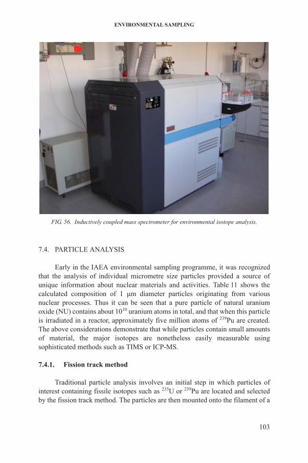
ENVIRONMENTAL SAMPLING
7.4. PARTICLE ANALYSIS
Early in the IAEA environmental sampling programme, it was recognized that the analysis of individual micrometre size particles provided a source of unique information about nuclear materials and activities. Table 11 shows the calculated composition of 1 μm diameter particles originating from various nuclear processes. Thus it can be seen that a pure particle of natural uranium oxide (NU) contains about 1010 uranium atoms in total, and that when this particle is irradiated in a reactor, approximately five million atoms of 239Pu are created. The above considerations demonstrate that while particles contain small amounts of material, the major isotopes are nonetheless easily measurable using sophisticated methods such as TIMS or ICP-MS.
FIG. 56. Inductively coupled mass spectrometer for environmental isotope analysis.
103
7.4.1. Fission track method
Traditional particle analysis involves an initial step in which particles of interest containing fissile isotopes such as 235U or 239Pu are located and selected by the fission track method. The particles are then mounted onto the filament of a
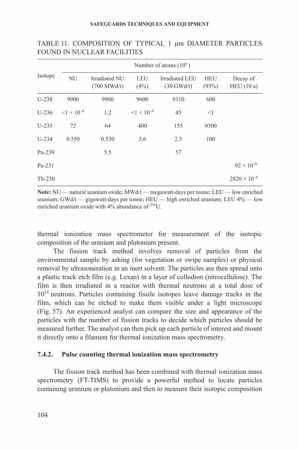
SAFEGUARDS TECHNIQUES AND EQUIPMENT
thermal ionization mass spectrometer for measurement of the isotopic composition of the uranium and plutonium present.
The fission track method involves removal of particles from the environmental sample by ashing (for vegetation or swipe samples) or physical removal by ultrasoneration in an inert solvent. The particles are then spread onto a plastic track etch film (e.g. Lexan) in a layer of collodion (nitrocellulose). The film is then irradiated in a reactor with thermal neutrons at a total dose of 1014 neutrons. Particles containing fissile isotopes leave damage tracks in the film, which can be etched to make them visible under a light microscope (Fig. 57). An experienced analyst can compare the size and appearance of the particles with the number of fission tracks to decide which particles should be measured further. The analyst can then pick up each particle of interest and mount it directly onto a filament for thermal ionization mass spectrometry.
TABLE 11. COMPOSITION OF TYPICAL 1 μm DIAMETER PARTICLES FOUND IN NUCLEAR FACILITIES
Isotope
Number of atoms (106 )
NU Irradiated NU(700 MWd/t)
LEU(4%)
Irradiated LEU(30 GWd/t)
HEU(93%)
Decay ofHEU (10 a)
U-238 9900 9900 9600 9310 600
U-236 <1 × 10⁻⁶ 1.2 <1 × 10⁻⁶ 45 <1
U-235 72 64 400 155 9300
U-234 0.550 0.530 3.6 2.5 100
Pu-239 5.5 57
Pa-231 92 × 10–6
Th-230 2820 × 10–6
Note: NU — natural uranium oxide; MWd/t — megawatt-days per tonne; LEU — low enriched uranium; GWd/t — gigawatt-days per tonne; HEU — high enriched uranium; LEU 4% — low enriched uranium oxide with 4% abundance of 235U.
104
7.4.2. Pulse counting thermal ionization mass spectrometry
The fission track method has been combined with thermal ionization mass spectrometry (FT-TIMS) to provide a powerful method to locate particles containing uranium or plutonium and then to measure their isotopic composition
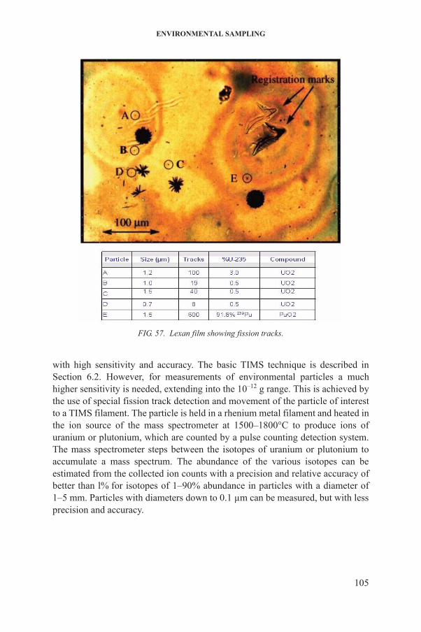
ENVIRONMENTAL SAMPLING
with high sensitivity and accuracy. The basic TIMS technique is described in Section 6.2. However, for measurements of environmental particles a much higher sensitivity is needed, extending into the 10–12 g range. This is achieved by the use of special fission track detection and movement of the particle of interest to a TIMS filament. The particle is held in a rhenium metal filament and heated in the ion source of the mass spectrometer at 1500–1800°C to produce ions of uranium or plutonium, which are counted by a pulse counting detection system. The mass spectrometer steps between the isotopes of uranium or plutonium to accumulate a mass spectrum. The abundance of the various isotopes can be estimated from the collected ion counts with a precision and relative accuracy of
FIG. 57. Lexan film showing fission tracks.
105
better than l% for isotopes of 1–90% abundance in particles with a diameter of 1–5 mm. Particles with diameters down to 0.1 µm can be measured, but with less precision and accuracy.
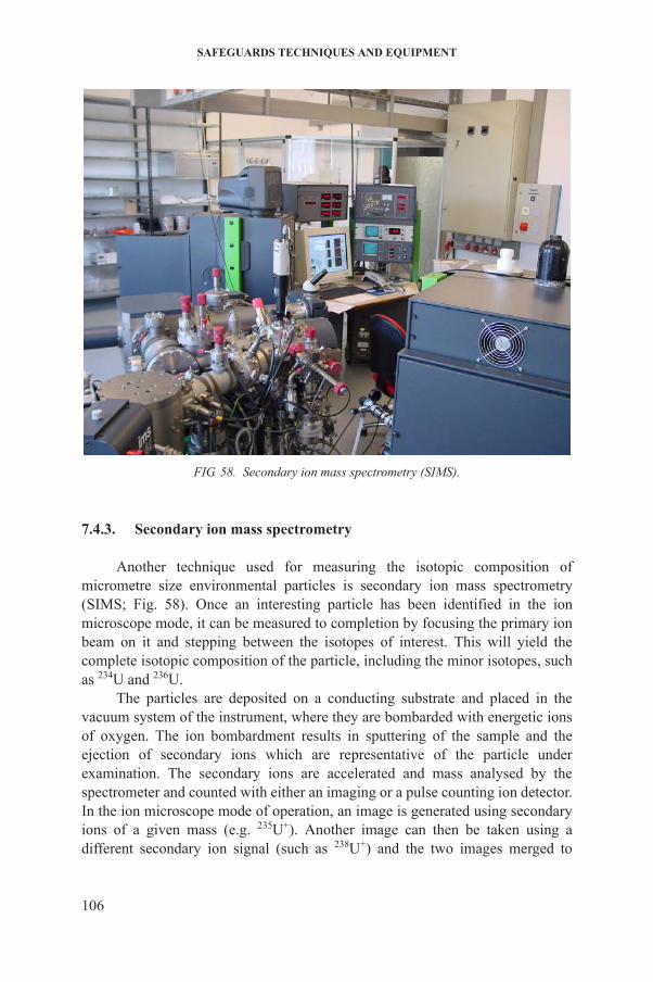
SAFEGUARDS TECHNIQUES AND EQUIPMENT
7.4.3. Secondary ion mass spectrometry
Another technique used for measuring the isotopic composition of micrometre size environmental particles is secondary ion mass spectrometry (SIMS; Fig. 58). Once an interesting particle has been identified in the ion microscope mode, it can be measured to completion by focusing the primary ion beam on it and stepping between the isotopes of interest. This will yield the complete isotopic composition of the particle, including the minor isotopes, such as 234U and 236U.
The particles are deposited on a conducting substrate and placed in the vacuum system of the instrument, where they are bombarded with energetic ions of oxygen. The ion bombardment results in sputtering of the sample and the
FIG. 58. Secondary ion mass spectrometry (SIMS).
106
ejection of secondary ions which are representative of the particle under examination. The secondary ions are accelerated and mass analysed by the spectrometer and counted with either an imaging or a pulse counting ion detector. In the ion microscope mode of operation, an image is generated using secondary ions of a given mass (e.g. 235U+). Another image can then be taken using a different secondary ion signal (such as 238U+) and the two images merged to

ENVIRONMENTAL SAMPLING
obtain the ratio of 235U to 238U for each particle in the field of view (typically 150 mm in diameter). By scanning 100–200 fields in one session, it is possible to interrogate several thousand particles by this method, thus giving a distribution of the 235U enrichments found in the particles from a sample.
The sensitivity of SIMS for uranium particles is limited by the secondary ion production and extraction efficiency (approximately 0.1% under typical measurement conditions). Therefore, a uranium particle 1 μm in diameter containing 1010 total uranium atoms would be expected to yield approximately 107 ions of the major isotope (238U) and approximately 105 ions of the minor isotope (235U) under ideal conditions. Practical considerations such as pre-sputtering and duty cycle would reduce these values by as much as a factor of 10. The result is that the enrichment or ratio of 235U to 238U can only be measured with 1–5% uncertainty for a pure uranium particle that is 1 μm in size. In reality, particles encountered in environmental samples are frequently smaller or less pure, and certain interference effects can also reduce the quality of such data.
For better performance, especially on small particles and for the uranium minor isotopes, a large geometry SIMS (LG-SIMS) instrument is available. The newly completed Clean Laboratory Extension of the IAEA Environmental Sample Laboratory is a state-of-the-art facility specifically designed for operation of an LG-SIMS for safeguards. The advantage of this larger instrument is higher throughput for better sensitivity coupled with higher mass resolution for greater freedom from molecular interferences that can give false measurements, especially for the minor isotopes of uranium (234U and 236U).
7.4.4. Scanning electron microscopy with electron probe analysis
Another method of locating particles containing elements of interest is the use of a scanning electron microscope combined with energy dispersive X ray spectrometry (Fig. 59). Particles of interest are removed from the sample using adhesive carbon discs, which are introduced into the electron microscope. Under high magnification (500–5000×), the particles are examined and the backscattered electron signal is used to search for particles containing heavy elements. These particles can then be measured by energy dispersive XRF spectrometry to give a semiquantitative elemental analysis. Particles containing
107
uranium or plutonium can be identified in this way; their size and morphology, as well as other elements present, will give information about the process that created them. An analysis may take several hours, whereby elemental composition can be measured with an accuracy down to element ratios of one part per thousand (0.1%). Particles identified in this way can be manipulated inside the vacuum system of the SEM or off-line with an optical microscope, and further

SAFEGUARDS TECHNIQUES AND EQUIPMENT
analysis can be carried out by bulk, SIMS or other mass spectrometric methods to obtain a complete elemental and isotopic analysis of a single interesting particle.
FIG. 59. Scanning electron microscope for particle analysis.
108
8. NEW AND NOVEL TECHNOLOGIES
Emerging and future needs for safeguards verification will require innovative technological solutions to meet current and future verification challenges in an environment where increasing numbers and types of nuclear facilities exist, with an increasing potential risk of the proliferation of sensitive technologies. The verification system has to be further developed taking full account of advances in present safeguards verification techniques (‘new technologies’) and through the exploration of innovative technologies that are either already available or are under investigation in other branches of science and technology not traditionally related to safeguards (‘novel technologies’). The early detection of undeclared facilities, activities and materials has become a major safeguards task and plays a primary role in providing independent safeguards conclusions regarding the completeness and correctness of a State’s nuclear material declaration. In particular, capabilities to detect undeclared nuclear activities (e.g. reprocessing or enrichment) are of prime interest and require that new methods and instruments be added to the IAEA’s safeguards ‘toolbox’. In many cases, safeguards implementation involving unannounced inspections and complementary access requires detection techniques to search for non-traditional elements and isotopes (such as americium, neptunium, beryllium and tritium) that might indicate the presence of clandestine nuclear activities. Future detection strategies may also include the detection and monitoring of other strong indicators of nuclear fuel cycle processes, and of signatures produced by those processes when they are operating. These may include a wide range of elements, alloys and chemical compounds in solid, liquid, gas and powder forms. Strategies may also include the detection of certain other types of emanations originating from processes related to the nuclear fuel cycle.
8.1. NEW TECHNOLOGIES
New technologies for safeguards purposes could address capabilities missing from routine verification tools and thereby enhance the effectiveness and efficiency of present verification systems (Table 12). Instrumentation based on new
109
technologies might be in its final development stage but not yet available for routine safeguards implementation. Such equipment will be authorized for routine use subject only to a careful assessment of aspects including its expected performance, usability and affordability, following successful field testing. New sensors for nuclear material detection and characterization, process monitoring equipment/techniques and analytical equipment are the main new technology drivers.
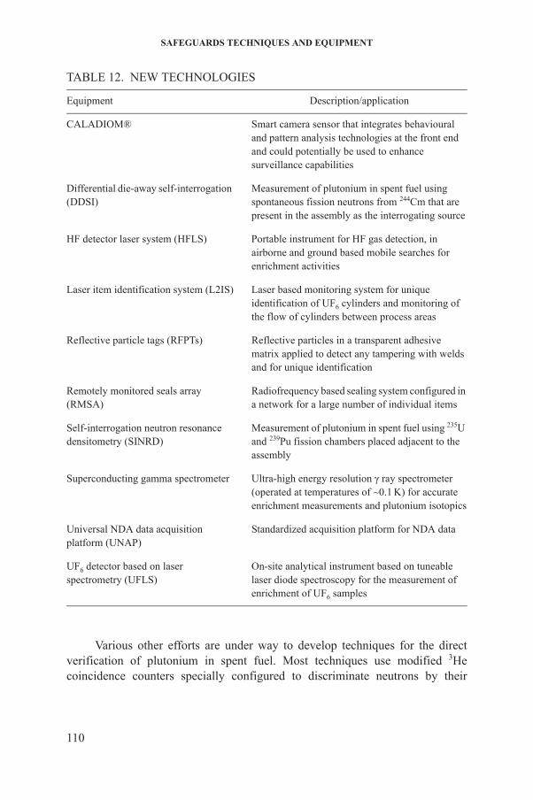
SAFEGUARDS TECHNIQUES AND EQUIPMENT
TABLE 12. NEW TECHNOLOGIES
Equipment Description/application
CALADIOM® Smart camera sensor that integrates behavioural and pattern analysis technologies at the front end and could potentially be used to enhance surveillance capabilities
Differential die-away self-interrogation (DDSI)
Measurement of plutonium in spent fuel using spontaneous fission neutrons from 244Cm that are present in the assembly as the interrogating source
HF detector laser system (HFLS) Portable instrument for HF gas detection, in airborne and ground based mobile searches for enrichment activities
Laser item identification system (L2IS) Laser based monitoring system for unique identification of UF6 cylinders and monitoring of the flow of cylinders between process areas
Reflective particle tags (RFPTs) Reflective particles in a transparent adhesive matrix applied to detect any tampering with welds and for unique identification
Remotely monitored seals array (RMSA)
Radiofrequency based sealing system configured in a network for a large number of individual items
Self-interrogation neutron resonance densitometry (SINRD)
Measurement of plutonium in spent fuel using 235U and 239Pu fission chambers placed adjacent to the assembly
Superconducting gamma spectrometer Ultra-high energy resolution γ ray spectrometer (operated at temperatures of ~0.1 K) for accurate enrichment measurements and plutonium isotopics
Universal NDA data acquisition platform (UNAP)
Standardized acquisition platform for NDA data
UF6 detector based on laser spectrometry (UFLS)
On-site analytical instrument based on tuneable laser diode spectroscopy for the measurement of enrichment of UF6 samples
110
Various other efforts are under way to develop techniques for the direct verification of plutonium in spent fuel. Most techniques use modified 3He coincidence counters specially configured to discriminate neutrons by their
NEW AND NOVEL TECHNOLOGIES
energy and analysis of neutron time distributions to determine the spontaneous and induced fissions in the sample.
Superconducting gamma spectrometry. This system is a cryogenic, ultra-high energy resolution γ ray spectrometer, operated at temperatures of approximately 0.1 K. It can be characterized as a cryogenic γ ray micro-calorimeter which measures the energy of radiation from the increase in temperature upon absorption of a γ ray. The system offers an order of magnitude improvement in energy resolution over conventional HPGe detectors and could be used to perform accurate measurements of enrichment and plutonium isotopic composition.
SINRD. Self-interrogation neutron resonance densitometry (SINRD) uses the unique neutron resonance cross-section structure for fissionable isotopes such as 235U, 233U, 239Pu and 241Pu. Its sensitivity is based on using the same fissile materials in the sample and in the fission chamber and results from the effect of resonance absorption lines in the transmitted flux being amplified by the corresponding (n,f) reaction peaks in the fission chamber. The amount of resonance absorption of these neutrons in the spent fuel can be measured using 235U and 239Pu fission chambers placed adjacent to the assembly.
DDSI. The differential die-away self-interrogation (DDSI) technique uses the spontaneous fission neutrons from 244Cm that are present in the assembly as the interrogating source. Fissile mass is determined from the induced thermal neutron fissions produced by reflected thermal neutrons originating from the spontaneous fission reaction. The sensitivity of the fissile mass measurement is enhanced by measuring the sample with and without a cadmium liner between the sample and the surrounding moderator (passive neutron albedo reactivity (PNAR)). The fertile mass is determined from the multiplicity analysis of the neutrons detected soon after the initial triggering neutron is detected.
CALADIOM®. CALADIOM® is a smart camera sensor developed for military applications. The sensor integrates behavioural and pattern analysis technologies at the front end and could potentially be used to enhance surveillance capabilities, effectiveness and capabilities.
RFPTs. Reflective particle tags (RFPTs) can be applied to a weld surface to identify the weld uniquely. These tags consist of reflective particles in a transparent adhesive matrix. The position and angular orientation of the particles are recorded by taking pictures of the tag from several different illumination
111
angles. The images taken during the verification process are compared with the images taken at the time the tag was applied. Since the adhesive that attaches the tag to the item to be identified is also the matrix that positions the reflectors, the tag cannot be detached by dissolving the adhesive in order to move it to another item without destroying the reflective particle pattern. The adhesive is a brittle material that crumbles when an attempt is made to peel the tag off.
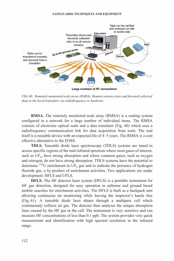
SAFEGUARDS TECHNIQUES AND EQUIPMENT
RMSA. The remotely monitored seals array (RMSA) is a sealing system configured in a network for a large number of individual items. The RMSA consists of electronic optical seals and a data translator (Fig. 60) which uses a radiofrequency communication link for data acquisition from seals. The seal itself is a reusable device with an expected life of 4–5 years. The RMSA is a cost effective alternative to the EOSS.
TDLS. Tuneable diode laser spectroscopy (TDLS) systems are tuned to access specific regions of the mid-infrared spectrum where most gases of interest, such as UF6, have strong absorption and where common gases, such as oxygen and nitrogen, do not have strong absorption. TDLS systems have the potential to determine 235U enrichment in UF6 gas and to indicate the presence of hydrogen fluoride gas, a by-product of enrichment activities. Two applications are under development: HFLS and UFLS.
HFLS. The HF detector laser system (HFLS) is a portable instrument for HF gas detection, designed for easy operation in airborne and ground based mobile searches for enrichment activities. The HFLS is built as a backpack unit allowing continuous air monitoring while leaving the inspector’s hands free
FIG. 60. Remotely monitored seals array (RMSA). Remote sensors store and forward collected data to the local translator via radiofrequency or hardwire.
112
(Fig. 61). A tuneable diode laser shines through a multipass cell which continuously collects air gas. The detector then analyses the unique absorption lines caused by the HF gas in the cell. The instrument is very sensitive and can measure HF concentrations of less than 0.1 ppb. The system provides very quick measurement and identification with high spectral resolution in the infrared range.

NEW AND NOVEL TECHNOLOGIES
UFLS. The UF6 detector based on laser spectrometry (UFLS) is an on-site analytical instrument based on TDLS which measures the enrichment of UF6
FIG. 61. HF detector laser system (HFLS) backpack unit.
113
samples. The system has passed a feasibility study and is now under development for field use. It determines the concentration of 235U and 238U in UF6 on-site with an accuracy of greater than 1% for 235U enrichment. The precise measurement of the isotopically broadened absorption peaks of 235U and 238U requires a mid-infrared laser with wide single mode tuning ranges, better than 4 cm–1 of continuous tuning at 1290 cm–1 and less tuning at 852 cm–1. In contrast to mass
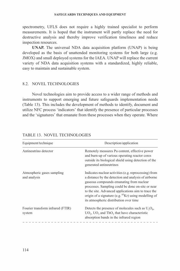
SAFEGUARDS TECHNIQUES AND EQUIPMENT
spectrometry, UFLS does not require a highly trained specialist to perform measurements. It is hoped that the instrument will partly replace the need for destructive analysis and thereby improve verification timeliness and reduce inspection resources.
UNAP. The universal NDA data acquisition platform (UNAP) is being developed as the basis of unattended monitoring systems for both large (e.g. JMOX) and small deployed systems for the IAEA. UNAP will replace the current variety of NDA data acquisition systems with a standardized, highly reliable, easy to maintain and sustainable system.
8.2. NOVEL TECHNOLOGIES
Novel technologies aim to provide access to a wider range of methods and instruments to support emerging and future safeguards implementation needs (Table 13). This includes the development of methods to identify, document and utilize NFC process ‘indicators’ that identify the presence of particular processes and the ‘signatures’ that emanate from these processes when they operate. Where
TABLE 13. NOVEL TECHNOLOGIES
Equipment/technique Description/application
Antineutrino detector Remotely measures Pu content, effective power and burn-up of various operating reactor cores outside its biological shield using detection of the generated antineutrinos
Atmospheric gases samplingand analysis
Indicates nuclear activities (e.g. reprocessing) from a distance by the detection and analysis of airborne gaseous compounds emanating from nuclear processes. Sampling could be done on-site or near to the site. Advanced applications aim to trace the origin of a signature (e.g. 85Kr) using modelling of its atmospheric distribution over time
114
Fourier transform infrared (FTIR) system
Detects the presence of molecules such as U3O8, UO2, UO3 and ThO2 that have characteristic absorption bands in the infrared region
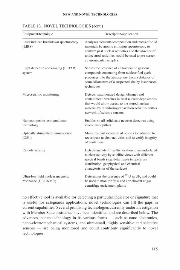
NEW AND NOVEL TECHNOLOGIES
no effective tool is available for detecting a particular indicator or signature that is useful for safeguards applications, novel technologies can fill the gaps in
Laser induced breakdown spectroscopy (LIBS)
Analyses elemental composition and traces of solid materials by atomic emission spectroscopy to confirm past nuclear activities and the absence of undeclared activities; could be used to pre-screen environmental samples
Light detection and ranging (LIDAR) system
Senses the presence of characteristic gaseous compounds emanating from nuclear fuel cycle processes into the atmosphere from a distance of some kilometres of a suspected site by laser based techniques
Microseismic monitoring Detects unauthorized design changes and containment breaches in final nuclear depositories that would allow access to the stored nuclear material by monitoring excavation activities with a network of seismic sensors
Nanocomposite semiconductor technology
Enables small solid state neutron detectors using silicon nanopillars
Optically stimulated luminescence (OSL)
Measures past exposure of objects to radiation to reveal past nuclear activities and to verify integrity of containers
Remote sensing Detects and identifies the location of an undeclared nuclear activity by satellite views with different spectral bands (e.g. determines temperature distribution, geophysical and chemical characteristics of the surface)
Ultra-low field nuclear magnetic resonance (ULF-NMR)
Determines the presence of 235U in UF6 and could be used to monitor flow and enrichment at gas centrifuge enrichment plants
TABLE 13. NOVEL TECHNOLOGIES (cont.)
Equipment/technique Description/application
115
current capabilities. Several promising technologies currently under investigation with Member State assistance have been identified and are described below. The advances in nanotechnology in its various forms — such as nano-electronics, nano-electromechanical systems, and ultra-small, highly sensitive and selective sensors — are being monitored and could contribute significantly to novel technologies.
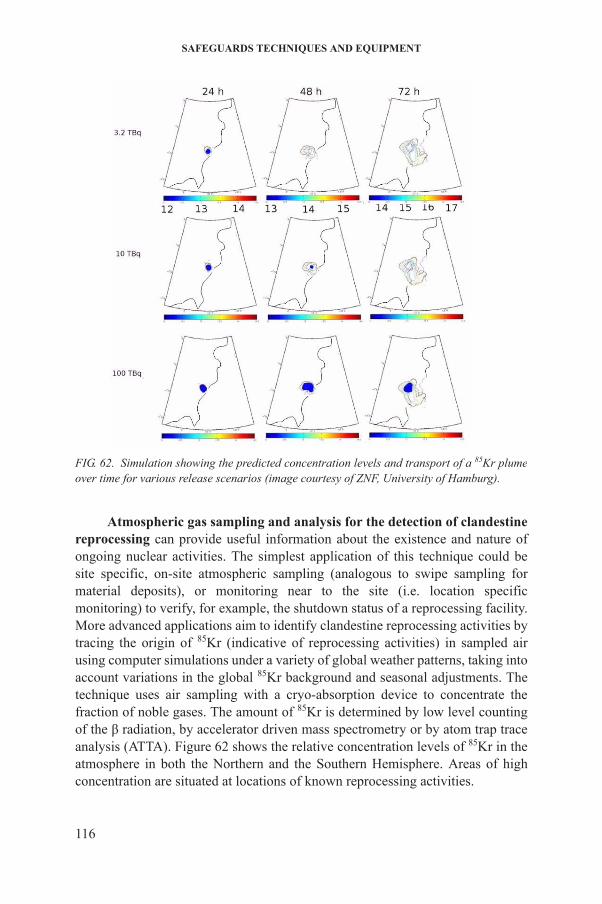
SAFEGUARDS TECHNIQUES AND EQUIPMENT
Atmospheric gas sampling and analysis for the detection of clandestine reprocessing can provide useful information about the existence and nature of ongoing nuclear activities. The simplest application of this technique could be site specific, on-site atmospheric sampling (analogous to swipe sampling for material deposits), or monitoring near to the site (i.e. location specific monitoring) to verify, for example, the shutdown status of a reprocessing facility. More advanced applications aim to identify clandestine reprocessing activities by tracing the origin of 85Kr (indicative of reprocessing activities) in sampled air using computer simulations under a variety of global weather patterns, taking into account variations in the global 85Kr background and seasonal adjustments. The
FIG. 62. Simulation showing the predicted concentration levels and transport of a 85Kr plume over time for various release scenarios (image courtesy of ZNF, University of Hamburg).
116
technique uses air sampling with a cryo-absorption device to concentrate the fraction of noble gases. The amount of 85Kr is determined by low level counting of the β radiation, by accelerator driven mass spectrometry or by atom trap trace analysis (ATTA). Figure 62 shows the relative concentration levels of 85Kr in the atmosphere in both the Northern and the Southern Hemisphere. Areas of high concentration are situated at locations of known reprocessing activities.
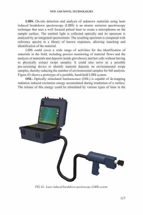
NEW AND NOVEL TECHNOLOGIES
LIBS. On-site detection and analysis of unknown materials using laser induced breakdown spectroscopy (LIBS) is an atomic emission spectroscopy technique that uses a well focused pulsed laser to create a microplasma on the sample surface. The emitted light is collected optically and its spectrum is analysed by an integrated spectrometer. The resulting spectrum is compared with reference spectra in a library of known responses, allowing matching and identification of the material.
LIBS could cover a wide range of activities for the identification of materials in the field, including process monitoring of material flows and the analysis of materials and deposits inside gloveboxes and hot cells without having to physically extract swipe samples. It could also serve as a possible pre-screening device to identify material deposits on environmental swipe samples, thereby reducing the number of environmental samples for full analysis. Figure 63 shows a prototype of a portable, hand-held LIBS system.
OSL. Optically stimulated luminescence (OSL) is capable of de-trapping radiation induced excitation energy accumulated during irradiation of a surface. The release of this energy could be stimulated by various types of laser in the
117
FIG. 63. Laser induced breakdown spectroscopy (LIBS) system.
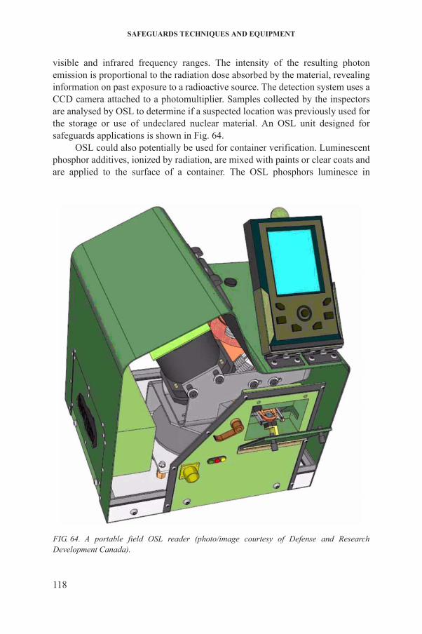
SAFEGUARDS TECHNIQUES AND EQUIPMENT
visible and infrared frequency ranges. The intensity of the resulting photon emission is proportional to the radiation dose absorbed by the material, revealing information on past exposure to a radioactive source. The detection system uses a CCD camera attached to a photomultiplier. Samples collected by the inspectors are analysed by OSL to determine if a suspected location was previously used for the storage or use of undeclared nuclear material. An OSL unit designed for safeguards applications is shown in Fig. 64.
OSL could also potentially be used for container verification. Luminescent phosphor additives, ionized by radiation, are mixed with paints or clear coats and are applied to the surface of a container. The OSL phosphors luminesce in
118
FIG. 64. A portable field OSL reader (photo/image courtesy of Defense and Research Development Canada).
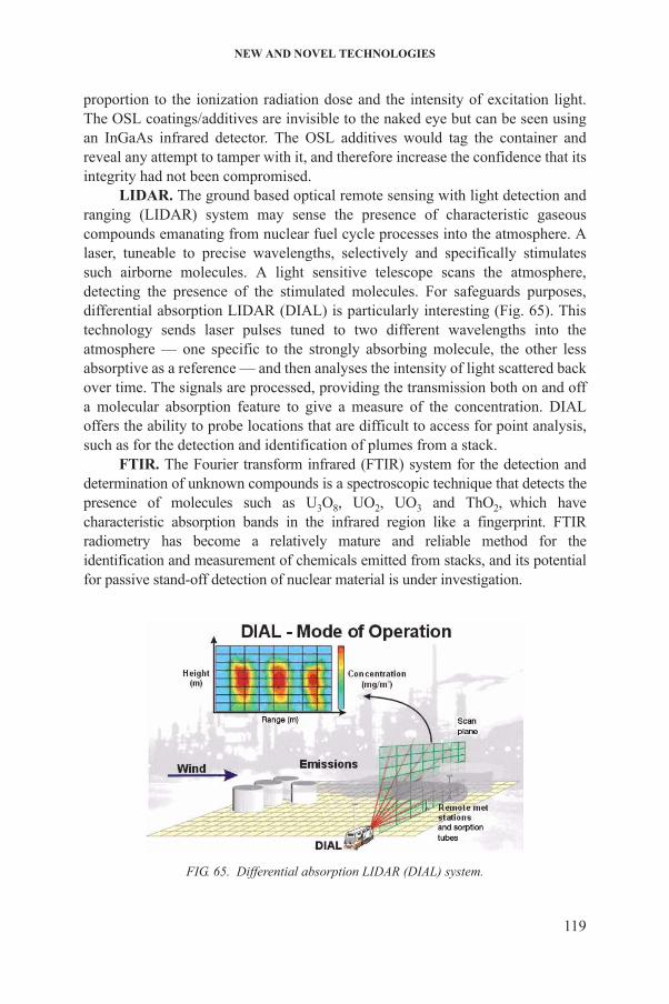
NEW AND NOVEL TECHNOLOGIES
proportion to the ionization radiation dose and the intensity of excitation light. The OSL coatings/additives are invisible to the naked eye but can be seen using an InGaAs infrared detector. The OSL additives would tag the container and reveal any attempt to tamper with it, and therefore increase the confidence that its integrity had not been compromised.
LIDAR. The ground based optical remote sensing with light detection and ranging (LIDAR) system may sense the presence of characteristic gaseous compounds emanating from nuclear fuel cycle processes into the atmosphere. A laser, tuneable to precise wavelengths, selectively and specifically stimulates such airborne molecules. A light sensitive telescope scans the atmosphere, detecting the presence of the stimulated molecules. For safeguards purposes, differential absorption LIDAR (DIAL) is particularly interesting (Fig. 65). This technology sends laser pulses tuned to two different wavelengths into the atmosphere — one specific to the strongly absorbing molecule, the other less absorptive as a reference — and then analyses the intensity of light scattered back over time. The signals are processed, providing the transmission both on and off a molecular absorption feature to give a measure of the concentration. DIAL offers the ability to probe locations that are difficult to access for point analysis, such as for the detection and identification of plumes from a stack.
FTIR. The Fourier transform infrared (FTIR) system for the detection and determination of unknown compounds is a spectroscopic technique that detects the presence of molecules such as U3O8, UO2, UO3 and ThO2, which have characteristic absorption bands in the infrared region like a fingerprint. FTIR radiometry has become a relatively mature and reliable method for the identification and measurement of chemicals emitted from stacks, and its potential for passive stand-off detection of nuclear material is under investigation.
119
FIG. 65. Differential absorption LIDAR (DIAL) system.
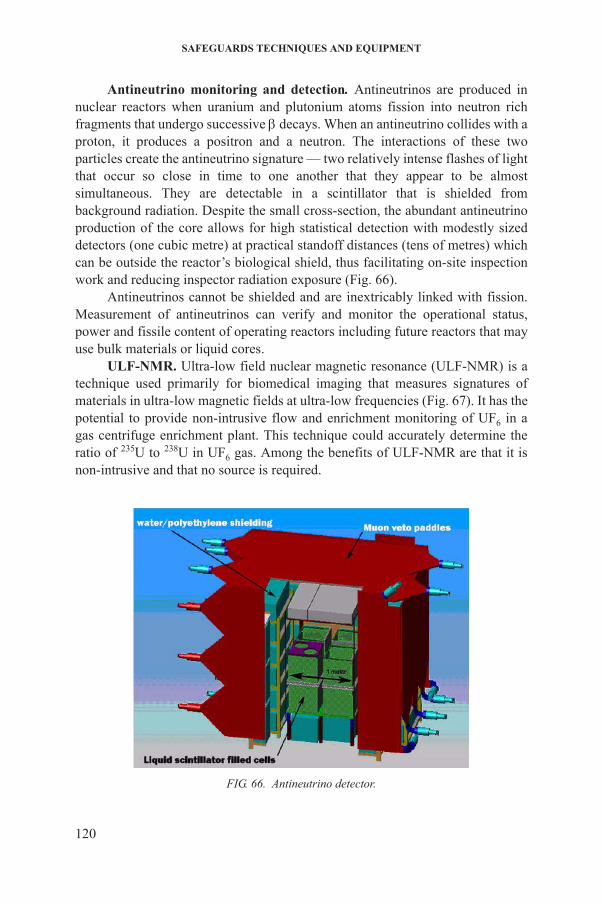
SAFEGUARDS TECHNIQUES AND EQUIPMENT
Antineutrino monitoring and detection. Antineutrinos are produced in nuclear reactors when uranium and plutonium atoms fission into neutron rich fragments that undergo successive decays. When an antineutrino collides with a proton, it produces a positron and a neutron. The interactions of these two particles create the antineutrino signature — two relatively intense flashes of light that occur so close in time to one another that they appear to be almost simultaneous. They are detectable in a scintillator that is shielded from background radiation. Despite the small cross-section, the abundant antineutrino production of the core allows for high statistical detection with modestly sized detectors (one cubic metre) at practical standoff distances (tens of metres) which can be outside the reactor’s biological shield, thus facilitating on-site inspection work and reducing inspector radiation exposure (Fig. 66).
Antineutrinos cannot be shielded and are inextricably linked with fission. Measurement of antineutrinos can verify and monitor the operational status, power and fissile content of operating reactors including future reactors that may use bulk materials or liquid cores.
ULF-NMR. Ultra-low field nuclear magnetic resonance (ULF-NMR) is a technique used primarily for biomedical imaging that measures signatures of materials in ultra-low magnetic fields at ultra-low frequencies (Fig. 67). It has the potential to provide non-intrusive flow and enrichment monitoring of UF6 in a gas centrifuge enrichment plant. This technique could accurately determine the ratio of 235U to 238U in UF6 gas. Among the benefits of ULF-NMR are that it is non-intrusive and that no source is required.
120
FIG. 66. Antineutrino detector.
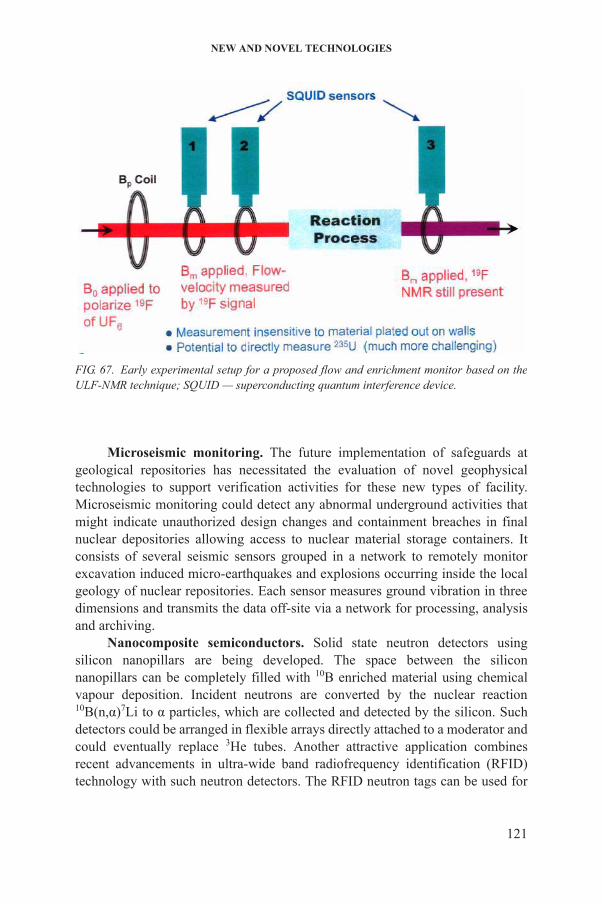
NEW AND NOVEL TECHNOLOGIES
Microseismic monitoring. The future implementation of safeguards at geological repositories has necessitated the evaluation of novel geophysical technologies to support verification activities for these new types of facility. Microseismic monitoring could detect any abnormal underground activities that might indicate unauthorized design changes and containment breaches in final nuclear depositories allowing access to nuclear material storage containers. It consists of several seismic sensors grouped in a network to remotely monitor excavation induced micro-earthquakes and explosions occurring inside the local geology of nuclear repositories. Each sensor measures ground vibration in three dimensions and transmits the data off-site via a network for processing, analysis and archiving.
Nanocomposite semiconductors. Solid state neutron detectors using silicon nanopillars are being developed. The space between the silicon nanopillars can be completely filled with 10B enriched material using chemical
FIG. 67. Early experimental setup for a proposed flow and enrichment monitor based on the ULF-NMR technique; SQUID — superconducting quantum interference device.
121
vapour deposition. Incident neutrons are converted by the nuclear reaction 10B(n,α)7Li to α particles, which are collected and detected by the silicon. Such detectors could be arranged in flexible arrays directly attached to a moderator and could eventually replace 3He tubes. Another attractive application combines recent advancements in ultra-wide band radiofrequency identification (RFID) technology with such neutron detectors. The RFID neutron tags can be used for
SAFEGUARDS TECHNIQUES AND EQUIPMENT
neutron monitoring, are totally passive and will operate indefinitely without battery power. The tag is compact, can be directly mounted on metal and has high performance in dense and cluttered environments.
Remote sensing. A satellite could view the Earth in different spectral bands covering the visible and infrared band. It could measure local ground and water temperatures to an absolute accuracy of 1 K. By further investigating other portions of the electromagnetic spectrum, it may be possible to detect and identify the location of an undeclared nuclear activity, for example, to detect the waste heat from a clandestine plutonium production reactor. Hyperspectral data allow for a quantitative estimation of geophysical and geochemical characteristics of the Earth’s surface and are therefore useful for assessing, for example, surface cover changes due to drilling, mining and milling activities.
122
9. DATA SECURITY
Data security is an important issue in the IAEA and must be ensured throughout the entire process of data handling, including collection, access, modification, evaluation and archiving. This section focuses on data generated by unattended and remote monitoring systems. These safeguards systems are permanently installed at facilities and are periodically visited by IAEA inspectors; they transmit data between different system components, and between systems and IAEA Headquarters, through unsecured transmission paths. The data need to be cryptographically authenticated to protect their integrity, and encrypted to prevent disclosure, thereby providing assurance of confidentiality to States. The use of commercial off the shelf VPN products for data transmission has been successfully implemented and the economics of using secure VPN tunnels over the Internet are extremely favourable. An IAEA-wide public key infrastructure (PKI) ensures secure communication within the IAEA and with its business partners and restricts access to safeguards data to authorized personnel.
Standardization of new equipment such as the NGSS and UNAP requires a common approach to addressing data security to ensure compatibility in data transmission and processing.
9.1. REQUIREMENTS
Data security requirements are derived from security targets, which dictate the security services and algorithms used. Table 14 provides a list of security services. In this list, the ‘authentication’ security service is identified as a separate service although it is often used as a supporting security service for others. For example, if the receiver’s identity is in doubt (i.e. the sender is unsure of who can decrypt the data), confidentiality cannot be guaranteed even if the data are encrypted. Similarly, integrity protection is of little value if the originator’s identity is in doubt.
This section addresses requirements for securing data in general. Specific State requirements are addressed in Section 9.3.
123
9.1.1. Authentication (integrity, authenticity)
When analysing data from unattended and remote monitoring systems, the data must be trustworthy in order for meaningful conclusions to be drawn. This is the most important requirement in terms of security.
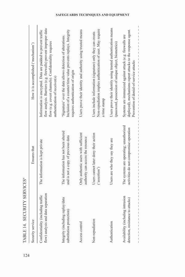
SAFEGUARDS TECHNIQUES AND EQUIPMENT
UR
ITY
SE
RV
ICE
Sa
Ens
ures
that
How
it is
acc
ompl
ishe
d (‘
mec
hani
sm’)
udin
g tr
affi
cat
a se
para
tion
The
info
rmat
ion
is k
ept p
riva
teIn
form
atio
n is
enc
rypt
ed. D
ata
are
padd
ed to
pre
vent
traf
fic
flow
ana
lysi
s. B
arri
ers
(e.g
. fir
ewal
ls)
prev
ent i
mpr
oper
dat
a fl
ow (
e.g.
cov
ert c
hann
els)
. Con
fide
ntia
lity
req
uire
s au
then
tica
tion
of
rece
iver
(s)
repl
ay/d
ata
on)
The
info
rmat
ion
has
not b
een
alte
red
and
is n
ot a
cop
y of
pre
viou
s da
ta‘S
igna
ture
’ ov
er th
e da
ta a
llow
s de
tect
ion
of a
lter
atio
ns.
Incl
usio
n of
a c
ount
er/t
ime
valu
e pr
even
ts r
epla
ys. I
nteg
rity
re
quir
es a
uthe
ntic
atio
n of
ori
gin
Onl
y au
then
tic
user
s w
ith s
uffi
cien
tau
thor
ity
can
acce
ss th
e re
sour
ceU
sers
pro
ve th
eir
iden
tity
and
auth
orit
y us
ing
trus
ted
mea
ns
Use
rs c
anno
t lat
er d
eny
thei
r ac
tion
(‘as
sert
ion’
)U
sers
incl
ude
info
rmat
ion
(sig
natu
re)
only
they
can
cre
ate.
N
on-r
epud
iati
on im
plie
s au
then
tica
tion
of
user
. May
req
uire
a ti
me
stam
p
Use
rs a
re w
ho th
ey s
ay th
ey a
reU
sers
pro
ve th
eir
iden
tity
usi
ng tr
uste
d au
then
tica
tion
mea
ns
(pas
swor
d, p
osse
ssio
n of
uni
que
obje
ct, b
iom
etri
cs)
ng in
trus
ion
to a
ttac
ks)
The
sys
tem
s ar
e op
erat
ing;
una
utho
rize
dac
tivi
ties
do
not c
ompr
omis
e op
erat
ion
Sys
tem
s ar
e im
mun
ized
aga
inst
atta
ck (
e.g.
fir
ewal
ls a
re
depl
oyed
), m
echa
nism
s re
port
att
acks
to th
e re
spon
se a
gent
. P
reve
ntio
n of
den
ial-
of-s
ervi
ce a
ttac
ks
124
TAB
LE
14.
SE
C
Sec
urity
ser
vice
Con
fide
ntia
lity
(inc
lfl
ow)
anal
ysis
and
d
Inte
grit
y (i
nclu
ding
su
bsti
tuti
on p
rote
cti
Acc
ess
cont
rol
Non
-rep
udia
tion
Aut
hent
icat
ion
Ava
ilab
ilit
y (i
nclu
dide
tect
ion,
res
ista
nce
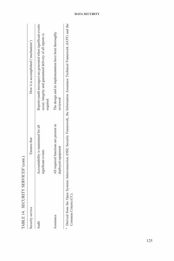
DATA SECURITY
Acc
ount
abil
ity
is m
aint
aine
d fo
r al
lsi
gnif
ican
t eve
nts
Rep
orts
(aud
it m
essa
ges)
are
gen
erat
ed w
hen
sign
ific
ant e
vent
s oc
cur;
inte
grit
y an
d gu
aran
teed
del
iver
y of
all
rep
orts
is
requ
ired
All
req
uire
d fu
ncti
ons
are
pres
ent i
nde
ploy
ed e
quip
men
t T
he d
esig
n an
d it
s im
plem
enta
tion
hav
e be
en th
orou
ghly
re
view
ed
Ope
n S
yste
ms
Inte
rcon
nect
ion
(OS
I) S
ecur
ity
Fra
mew
ork,
the
Inf
orm
atio
n A
ssur
ance
Tec
hnic
al F
ram
ewor
k (I
AT
F)
and
the
(C
C).
UR
ITY
SE
RV
ICE
Sa (co
nt.)
Ens
ures
that
How
it is
acc
ompl
ishe
d (‘
mec
hani
sm’)
125
Aud
it
Ass
uran
ce
aD
eriv
ed f
rom
the
Com
mon
Cri
teri
a
TAB
LE
14.
SE
C
Sec
urity
ser
vice
SAFEGUARDS TECHNIQUES AND EQUIPMENT
For this purpose, ‘trustworthy’ means that the data must originate from the intended source, must not have been changed in transit and must be assigned to a particular time frame. The IAEA requires that measures be in place to ensure the authenticity of transmitted and stored data. The term ‘authenticity’ refers to the combination of integrity (including replay/data substitution) and authentication (of origin) protection, as defined above.
9.1.2. Confidentiality
The IAEA has defined requirements for confidentiality. As a general rule, detailed safeguards information from the Agency equipment should not be made available to States. However, arrangements could be made for sharing certain data as part of the cooperation arrangements with State authorities.
Although integrity and authentication are of primary importance, some safeguards data may require confidentiality protection since knowledge of actually measured values may enable the facility operators to exploit instrument characteristics or inaccuracies. For example, if the actual measured value and the instrument accuracy are known, declarations could be manipulated to ensure that each declaration is within the bounds of measurement error while allowing a protracted diversion of small amounts of material. In addition, long term analysis of instrument data inaccuracy may allow the prediction of future inaccuracies. In such cases, instrument data may need to be protected until the instrument is recalibrated.
9.1.3. Non-repudiation
Non-repudiation protection is required for operator declaration data. Depending on the security mechanism, basic non-repudiation (of origin) may be inherent in the method used for integrity and authentication. For example, if public key based signatures are used, non-repudiation of origin is provided. Non-repudiation protection may require additional mechanisms to bind the time of signing to the signature.
9.1.4. Time stamping
126
For their analysis, inspectors need a reliable time stamp on all data collected. Trustworthy clocks of trusted storage facilities or a trusted time stamping service are possible solutions to this problem. Also, operator declarations will require the time of declaration to be included. For example, to allow an audit to be performed, there should be a clear sequence of declarations.
DATA SECURITY
The simplest way to record this sequence is to give a time stamp to each declaration.
9.1.5. Access control
Besides the encryption of data, which protects their confidentiality, several devices also use access control mechanisms in order to restrict the operation of devices to authorized users. Most such access control mechanisms require a two-factor authentication, usually based on a physical token and a password.
9.2. IMPLEMENTATION
Key lengths of cryptographic algorithms mainly depend on the time the data need to stay confidential or integrity protected. In order to use algorithms that adequately protect sensitive information and to plan ahead for possible changes in the use of cryptography, the IAEA follows the recommendations of relevant authorities, such as the International Organization for Standardization (ISO), National Institute of Standards and Technology (NIST), British Standards Institution (BSI), Direction centrale de la sécurité des systèmes d’information (DCSSI) and others. Safeguards information used in unattended and remote monitoring systems can be described by the general information model shown in Fig. 68 and summarized in Table 15. The model segregates data on the basis of their intended use as follows:
(a) Verification data are used during safeguards reviews carried out by approved IAEA inspectors.
(b) Technical data are used during technical reviews carried out by approved IAEA technical staff.
(c) Control data are used for the ‘real time’ control of equipment either by automated safeguards application programs or manually during inspection or maintenance activities.
Depending on the surveillance design, some technical data may also be included in ‘verification data’ if deemed important for the safeguards review.
127
Although some general conclusions may be drawn regarding the data types in the model, there will be exceptions, depending on the specific design of an unattended monitoring system.

SAFEGUARDS TECHNIQUES AND EQUIPMENT
9.2.1. Verification data
Typical verification data might consist of digital images, electronic seals status and sensor data (e.g. count rates of radiation devices or other measurement results). Verification data are evaluated during safeguards reviews carried out by approved IAEA inspectors. The evaluated data are compared with the operator’s declaration of nuclear material and/or activities and are assessed in the context of other information in deriving safeguards conclusions. All verification data require the highest level of integrity protection, and in many cases confidentiality protection, to ensure that the IAEA can independently verify and monitor the nuclear materials/activities by deploying its instruments.
9.2.2. Technical data
FIG. 68. Unattended and remote monitoring information model.
128
Technical data (‘state of health data’) might include status parameters for the environment (temperature, humidity, etc.) and equipment operation (battery level, failures, tamper indications, storage capacity, number of available download files, etc.). The daily technical review of such data makes it possible to detect failures of equipment or tampering early enough for remedial actions to be implemented.
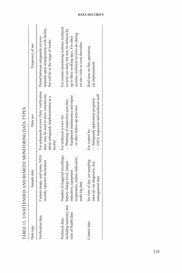
DATA SECURITY
TT
EN
DE
D A
ND
RE
MO
TE
MO
NIT
OR
ING
DA
TA T
YP
ES
Sam
ple
data
Dat
a us
eFr
eque
ncy
of u
se
Cam
era
imag
e, s
eal s
tatu
s, N
DA
re
cord
s, o
pera
tor
decl
arat
ion
For
saf
egua
rds
revi
ew. O
nly
‘ver
ific
atio
n da
ta’
may
be
used
to d
raw
con
clus
ions
ab
out s
afeg
uard
s im
plem
enta
tion
at a
fa
cilit
y
Per
iod
betw
een
safe
guar
ds r
evie
ws
depe
nds
upon
arr
ange
men
ts w
ith
faci
lity
bu
t will
be
in th
e ra
nge
of w
eeks
and
Num
ber o
f tri
gger
ed re
cord
ings
, ba
tter
y ch
arge
leve
l, ta
mpe
r in
dica
tion
, equ
ipm
ent
tem
pera
ture
, fai
lure
indi
cati
on,
audi
t log
dat
a
For
tech
nica
l rev
iew
for
:—
Pla
nnin
g of
insp
ecti
on a
ctiv
itie
s—
Equ
ipm
ent m
aint
enan
ce a
nd r
epai
ror
oth
er f
ollo
w-u
p ac
tivi
ties
For
rem
ote
mon
itor
ing
syst
ems,
tech
nica
l re
view
s ar
e da
ily
but m
ay b
e de
laye
d by
up to
thre
e w
orki
ng d
ays.
For
oth
er
syst
ems,
tech
nica
l rev
iew
s ar
e du
ring
on
-sit
e vi
sits
or
soon
ther
eaft
er
Set
tim
e of
day
, set
sam
plin
g in
terv
al, r
un d
iagn
osti
c, k
ey
man
agem
ent d
ata
For
con
trol
by:
—
Saf
egua
rds
appl
icat
ion
prog
ram
s —
IA
EA
insp
ecto
rs a
nd te
chni
cal s
taff
Rea
l tim
e on
-lin
e op
erat
ions
(as
impl
emen
ted)
129
TAB
LE
15.
UN
A
Dat
a ty
pe
Ver
ific
atio
n da
ta
Tech
nica
l dat
a,
incl
udin
g su
mm
ary
stat
e of
hea
lth d
ata
Con
trol
dat
a
SAFEGUARDS TECHNIQUES AND EQUIPMENT
All technical data need to be authenticated in order to ensure that failures, logs and indications of tampering are reliably reported to IAEA staff. Additionally, for data which may indicate increased equipment vulnerability, confidentiality protection will be required until remedial action can be taken. For example, state of health data indicating a failure of internal backup battery power may indicate an increased vulnerability to the removal of primary power. Such an indication might allow an adversary to optimize its attack on the equipment.
Confidentiality protection may only be needed for a limited period of time. For example, state of health data may only be sensitive until the equipment can be serviced. Thus, protection may only be required until the technical review is complete and remedial action has been taken.
It may be appropriate to provide integrity protection to some audit and other information for longer periods if its relevance cannot be determined during the initial technical review. Historical trends may have to be analysed to arrive at conclusions. In such situations, this information may also be included in the verification data.
9.2.3. Control data
Control data are used to permit sensors to be adjusted and controlled from IAEA premises. In such cases, it is necessary to ensure that remote log in and access controls are adequate for the secure control of equipment, including provisions for:
(1) Secure log in to the ‘collect computer’;(2) Initiation of file and data transfers;(3) Operational control of the remote monitoring system;(4) Activation of test routines in the collect computer;(5) Secure entry of commands into the collect computer, which may in turn
issue secure controls to attached sensors;(6) Updating of software.
Control data are transmitted in ‘real time’ and might include:
(a) Synchronization of sensors by date and time;
130
(b) Control of sensor operation (e.g. camera focus, pan/tilt, sampling rate);(c) Activation of test and calibration routines in sensors.
Authentication of all such data is required to prevent malicious modification. Confidentiality is required for some control data, since observation may reveal sensitive information (such as the criteria used to adjust surveillance

DATA SECURITY
triggers). Access control and availability protection must be provided to mitigate the risk of denial of service attacks. All of these protection measures are required throughout the lifetime of the data.
9.2.4. Virtual private networks
A VPN connects components and resources of one network (or a single computer) securely to the resources of another network using public Internet services. The IAEA uses a certified, commercially available hardware based VPN product with a built-in firewall. These VPN devices now support the latest encryption methods. The VPN unit has undergone extensive field testing and independent vulnerability assessments. The assessments concluded that at the sites that were evaluated, the VPN solution being used appeared to be properly configured and was appropriately protecting the devices behind it. Also, the network topology for the sites that were examined appeared to be appropriately designed so that critical systems and components were appropriately isolated from the Internet.
The VPN devices use the standard secure Internet Protocol Security (IPSec) protocol and transmit all data in encapsulated security payload (ESP) packets. Additionally, IPSec incorporates the following characteristics:
— Transport and data integrity: ensures that the source of data does not change during a session and that data are not tampered with during transmission.
— Data confidentiality: ensures that intercepted data cannot be read by unauthorized parties during transmission.
— User authentication: ensures that a session is only established with a trusted user.
9.2.5. Safeguards mailbox
The safeguards mailbox enables secure communication between the IAEA and States and/or facility operators. Declarations are simply sent to the safeguards mailbox as email attachments. The messages are encoded in a standard format, and are signed and encrypted using keys available via PKI. The State authority and the IAEA choose a certificate authority that they trust and obtain the required
131
certificates and keys for signing and encrypting. This enables the State authority and the IAEA to securely and verifiably deliver and receive messages.
Since declaration processing is triggered by the receipt of email and does not have to be scheduled, the State can obtain almost instantaneous confirmation that its submission has been successfully received by the IAEA. Thereafter, any data sharing could be triggered immediately without further delay.
SAFEGUARDS TECHNIQUES AND EQUIPMENT
The IAEA recommends the safeguards mailbox to States. This system is already in operation for a number of facilities around the world and has many advantages for States over the current declaration processing system in that it:
— Allows the State to very quickly receive confirmation that messages sent have been received by the IAEA;
— Allows the State to verify the signature of messages received from the IAEA;
— Allows the State and the IAEA to exchange messages encrypted by an authority that the State trusts;
— Can very easily encapsulate and isolate each declaration submission;— Only requires readily available, commercial off the shelf software;— Does not require any IAEA equipment to be installed anywhere, and does
not require the purchase of any special hardware;— Can be used for any secure communication with the IAEA.
9.3. STATE REQUIREMENTS
States’ concerns mainly relate to ensuring that their information is kept confidential and that the safeguards programme reliably reflects their conformance to relevant agreements. The Model Additional Protocol1 states that:
“Communication and transmission of information … shall take due account of the need to protect proprietary or commercially sensitive information or design information which [the State] regards as being of particular sensitivity.” (Article 14(b))
“The Agency shall maintain a stringent regime to ensure effective protection against disclosure of commercial, technological and industrial secrets and other confidential information coming to its knowledge, including such information coming to the Agency’s knowledge in the implementation of this Protocol.” (Article 15(a))
An IAEA policy paper on remote monitoring stated that encryption was to
132
be applied during data transmission, as agreed with the State; that transmitted
1 INTERNATIONAL ATOMIC ENERGY AGENCY, Model Protocol Additional to the Agreement(s) between State(s) and the International Atomic Energy Agency for the Application of Safeguards, INFCIRC/540, IAEA, Vienna (1997).
DATA SECURITY
data were to be treated and stored as ‘safeguards confidential’ information; and that States had the right to know the kind of information being transmitted, as well as the right to protection of the data through appropriate encryption.
It is noted that these State requirements are specifically directed towards protecting the confidentiality of “commercial, technological and industrial secrets”. This State requirement for confidentiality will not normally require additional security mechanisms while information is contained within a physically secure facility provided by the State. This State requirement will normally only apply to information while it is within communications networks provided by the IAEA, on transportable media, or within IAEA offices or inspection equipment.
For UMSs and remote monitoring systems, State confidentialityrequirements have an impact upon two areas:
(1) Ensuring adequate protection of data links between sensors and collect computers if not otherwise protected by physical boundaries provided by the State;
(2) Ensuring adequate protection of the data stored on transportable media.
In addition, if the security of laptop computers used by inspection and technical staff is not addressed elsewhere, it is important to ensure that any State information stored or viewed on these devices is adequately protected.
Confidentiality protection must be strong enough to withstand any external attack. Since the owner of the information being protected is in the best position to judge the value of these data, provision will need to be made to satisfy the requirements regarding data protection as specified by States. In the absence of specification by a State, the IAEA’s security architecture specifies a minimum strength level suitable for general commercial practice and equivalent to the safeguards confidential classification specified by the IAEA.
133

.
LIST OF ACRONYMS AND ABBREVIATIONS
3DLR 3-D laser range finder
ADAM Autonomous data acquisition module
ADSL Asymmetric digital subscriber line
AEFC Advanced experimental fuel counter
ALIP All in one surveillance portable system
ALIS All in one surveillance system
AMAGB Advanced material accountancy glovebox counter
ATPM Advanced thermohydraulic power monitor
ATTA Atom trap trace analysis
AWCC Active well coincidence counter
BNCNC Birdcage neutron counter
BSI British Standards Institution
BWR Boiling water reactor
C/S Containment and surveillance
CANDU Canadian uranium reactor
CAPS Cap seal (metallic)
CBVB CANDU bundle verifier
CC Common Criteria
135
CCD Charge coupled device
CCDM CANDU core discharge monitor
CCRM Cask car radiation monitor
SAFEGUARDS TECHNIQUES AND EQUIPMENT
CCTV Closed circuit television
CCU Camera control unit
CEMO Continuous enrichment monitor
CHEM Cascade header enrichment monitor
CMPU Combined procedure for uranium concentration and enrichment assay
CRPS Cask radiation profiling system
DCM 14 Digital camera module
DCPD Directional canister passage detector
DCSSI Direction centrale de la sécurité des systèmes d’information
DCVD Digital Cerenkov viewing device
DDSI Differential die-away self-interrogation
DIAL Differential absorption LIDAR
DIS Digital image surveillance
DIV Design information verification
DMOS Digital multi-camera optical surveillance system
DRNC Drawer counter
DSOS Digital single camera optical surveillance system
DSP Digital signal processing
136
ECGS Electrically cooled germanium system
ENGM Entrance gate monitor
EOSS Electronic optical sealing system
LIST OF ACRONYMS AND ABBREVIATIONS
ESP Electronic sensor platform
ESP Encapsulated security payload
EVRB Ex-vessel transfer radiation monitor (B-side)
EVRM Ex-vessel transfer radiation monitor
EXGJ Exit gate radiation monitor
EXGM Exit gate monitor
FAAS MOX fuel assembly/capsule assay system
FAST FAST (company) multiple camera surveillance system (Euratom)
FBOS Fibre optic general purpose seal
FC Fission chamber
FDET Fork detector irradiated fuel measuring system
FMAT Fresh MOX attribute tester
FPAS Fuel pin/pallet assay system
FRAM Fixed-Energy, Response Function Analysis with Multiple Efficiency
FTIR Fourier transform infrared
FTPV Fuel transfer video
FT-TIMS Fission track thermal ionization mass spectrometry
FUGM Fugen chute monitor
137
FUGR Fugen gate monitor system
GARS General Advanced Review Station Software
GBAS Glovebox assay system

SAFEGUARDS TECHNIQUES AND EQUIPMENT
GDTV Gemini digital video system
GPRS General Packet Radio Service
GPRT Ground penetrating radar technology
GRPM GRAND-Based Reactor Power Monitor
GW-d/t Gigawatt-days per tonne
HALW High active liquid waste
HBAS Hold-up blender assay system
HCMS Hot cell monitor system (Ignalina)
HDIS HAWK-SG digital image surveillance
HDVM HTTR door valve monitor
HEU High enriched uranium
HFLS HF detector laser system
HHNM Hand-held neutron monitor
HILL High intensity LED light
HKED Hybrid K-edge densitometry
HLNC High level neutron coincidence counter
HMMS Hulls monitor and measurement system
HPGe High purity germanium detector
HRGS High resolution gamma spectroscopy
138
HTTR HTTR unattended fuel flow monitor
HWR Heavy water reactor
IATF Information Assurance Technical Framework
LIST OF ACRONYMS AND ABBREVIATIONS
IC Ionization chamber
ICP-MS Inductively coupled plasma mass spectrometry
ICVD Improved Cerenkov viewing device
IDAS Isotope dilution alpha spectrometry
IDGS Isotope dilution gamma ray spectrometry
IDMS Isotope dilution mass spectrometry
IHVS Integrated head-end verification system
IMCA InSpector 2000 multichannel analyser
IMCC InSpector 2000 multichannel analyser paired withCdZnTe detector
IMCF Integrated monitoring system for Chernobyl spent fuel conditioning facility
IMCG InSpector 2000 multichannel analyser paired withHPGe detector
IMCN InSpector 2000 multichannel analyser paired withNaI detector
INCC IAEA neutron coincidence counting
INVS Inventory sample counter
IPCA Improved plutonium canister assay
IPLC IPCA load cell system
IPSec Internet Protocol Security
IRRM Institute for Reference Materials and Measurements
139
(Belgium)
IRAT Irradiated fuel attribute tester
ISDN Integrated services digital network
SAFEGUARDS TECHNIQUES AND EQUIPMENT
ISFM Ignalina NPP spent fuel monitor
ISO International Organization for Standardization
ISOCS In Situ Object Counting System
ISSF Integrated safeguards system for the unattended monitoring of spent fuel transfers
ISVS Integrated spent fuel verification system
IT Interrogator transceiver
JCSS JRC CANDU sealing system
JRC Joint Research Centre
KEDG K-edge densitometer
KEDG K-edge densitometry
L2IS Laser item identification system
LCBS Load cell based weighing system
LEU Low enriched uranium
LG-SIMS Large geometry secondary ion mass spectrometry
LIBS Laser induced breakdown spectroscopy
LIDAR Light detection and ranging
LMCV Laser mapping system for containment verification
LNCS Large neutron multiplicity counter
LNMC Large neutron multiplicity counter
140
LRFO Laser range finder option
LSA Laser surface authentication
LWR Light water reactor
LIST OF ACRONYMS AND ABBREVIATIONS
MAGB Material accountancy glovebox counter
MCNP Monte Carlo N particle transport code
MGA Multi-Group Analysis
MGAU Multi-Group Analysis for Uranium
MGBS MiniGRAND based system
MIMS Spent fuel integrated monitoring system (BN-350)
MIMZ Measurement and integrated monitoring system (Zwilag)
MiniGRAND Miniature gamma ray and neutron detector
MMCA Miniature multichannel analyser
MMCC Miniature multichannel analyser paired withCdZnTe detector
MMCG Miniature multichannel analyser paired withHPGe detector
MMCN Miniature multichannel analyser paired withNaI detector
MMCT Mobile monitoring system for container transport
MMCU Multichannel analyser for unattended operation
MMS Material monitoring system
MOSS Multi-camera optical surveillance system
MOX Mixed oxide (usually U–Pu oxide mixtures)
MSSP Member State support programme
141
MUND Mobile unit neutron detector
MWd/t Megawatt-days per tonne
SAFEGUARDS TECHNIQUES AND EQUIPMENT
NBL New Brunswick Laboratory
NDA Non-destructive analysis (often referred toas non-destructive assay)
NGAT Neutron and gamma attribute tester
NGSS Next generation of surveillance system
NIST National Institute of Standards and Technology(United States of America)
NML Nuclear Material Laboratory (IAEA)
NU Natural uranium oxide
NWAL Network of Analytical Laboratories
OFPS Optical fibre radiation probe system
O–I Operator–inspector
OLEM On-line enrichment monitor
OSI Open Systems Interconnection
OSL Optically stimulated luminescence
PCAS Plutonium canister assay system
PIMS Plutonium inventory monitoring system
PKI Public key infrastructure
PNAR Passive neutron albedo reactivity
PNCL Passive neutron coincidence collar
142
PNUH Portable neutron uranium hold-up monitor
PPMD Portable pressure measurement device
PSMC Plutonium scrap multiplicity counter
LIST OF ACRONYMS AND ABBREVIATIONS
PSTN Public switched telephone network
PWCC Passive well coincidence counter
PWR Pressurized water reactor
RAID Redundant array of independent disks
RFID Radiofrequency identification
RFPT Reflective particle tag
RHMS Rokkasho hull monitor system
RMDC Remote Monitoring Data Centre (IAEA)
RMSA Remotely monitored seals array
RSAC Regional system of accounting for and control of nuclear material
SAL Safeguards Analytical Laboratory (IAEA)
SCANDU Evaluation program for CANDU systems
SDIS Server based digital image surveillance
SEGM Silo entry gamma monitor
SEM Scanning electron microscopy
SFAT Spent fuel attribute tester
SFCC Spent fuel coincidence counter
SFFM Spent fuel flow monitor
SIDS Sample identification system
143
SIMS Secondary ion mass spectrometry
SINRD Self-interrogation neutron resonance densitometry
SMM1 Solution monitoring and measurement system type 1
SAFEGUARDS TECHNIQUES AND EQUIPMENT
SMM2 Solution monitoring and measurement system type 2
SMMS Solution monitoring and measurement system
SMOPY Safeguards MOX python
SQUID Superconducting quantum interference device
SRBS Shift register based system
SSAC State system of accounting for and control ofnuclear material
STVS Short term TV system
SVSC Secure vial sealing container
TAMS Tank monitoring system
TDLS Tuneable diode laser spectroscopy
TIMS Thermal ionization mass spectrometry
TRFS T-1 two-way radiofrequency seal
UFBC Universal fast breeder counter
UFDM Unattended FORK detector monitor
UFFM Unattended fuel flow monitor
UFLS UF6 detector based on laser spectrometry
UFSM Unattended spent fuel monitor
ULF-NMR Ultra-low field nuclear magnetic resonance
ULTG Ultrasonic thickness gauge
144
UMS Unattended monitoring system
UMTS Universal mobile telecommunications system
UNAP Universal NDA data acquisition platform
LIST OF ACRONYMS AND ABBREVIATIONS
UNCL Uranium neutron coincidence collar
USFM Unattended spent fuel monitor
USSB Ultrasonic sealing bolt
UWCC Underwater coincidence counter
UWTV Underwater television
VACOSS Variable coding seal system
VCAS Vitrified waste canister assay system
VCOS VACOSS-S electronic seal(variable code sealing system)
VIFB CANDU spent fuel bundle counter
VIFC CANDU core discharge monitor
VIFD CANDU yes/no monitor
VIFM VXI integrated fuel monitor
VLAN Virtual local area network
VMOS VACOSS-S/MOSS system
VOID Improved adhesive seal
VPN Virtual private network
VSEU Video system multiplex dual use surveillance system
VSPC Video system (facility specific)
VWCC Vitrified waste coincidence counter
145
WCAA Waste crate assay system A
WCAS Waste crate assay system
WCSS Wall containment sensor system

SAFEGUARDS TECHNIQUES AND EQUIPMENT
WDAS Waste drum assay system
XRF X ray fluorescence
XRFA X ray fluorescence analyser
146

@������
��������� ���������������� ��������������������������������� �������������������������� ������������ ���������
����������������������������������� �������������������������������� ����� !"����������
������ �#��������� ��� ��$�����%&'�(� �������)�����*�+!,�*�-.-/��
+�������0�1%.�-�2/.3�4444�5�6�70�1%.�-�2/.3�44''��
���0����$��8������ ��������5�(���� �0�� �099���������� ��������
!� " �#:�������;��������$��������)��/3/��<=..23�<��������
+�������0�1-/�/�>-'�&-�3'�5�6�70�1-/�/�>-'�3'�&.��
���0��������������8������������5�(���� �0�� �099��������=��=���������
$���%�<������������ ����&>3.�6������<$��� � ��/33��;�������*#�/343%=&-&%��� ���
+�������0�.='33='%>=-&>4�5�6�70�.='33='%>=-&>3��
���0���� ��������8�����������5�(���� �0�� �099���������������
)������������?�!�������; ����.=>-%2�!��� ���)����" �����"� �����@.:�2:-��
+�������0�1%.-�4&>�/%%>�5�6�70�1%.-�4&>�4%%3��
���0���������� 8����������������5�(���� �0�� �099��������������������
$& ������������ ������!�����0�!���������������?������� ���!������ ����+����� ��� �� ������"��<�7�/.3-��<���?�
$'�$&���(�! $ ������!A�� �)�"���@�����$��-&4��.'3�/.�������2��
+�������0�1&/3�/%%3-�>-%&�5�6�70�1&/3�/'&'/�.%&%��
���0������8��������B�5�(���� �0�� �099������������B�
) � ��%��� �������@������������"�<"C�./'�D@������� ��.E��6��=33.3.�,������
+�������0�1->'�2�./.�&.�5�6�70�1->'�2�./.�&&>3��
���0���� ���8��� �����������5�(���� �0�� �099������� �����������
)���$�6���=�� ��>������:����������"��<�7�/>��6=4>2/.������!���7�.2��
+�������0�1--�.�&/�3.�&2�&2�5�6�70�1--�.�&/�3.�23�23��
���0������� 8������ ����5�(���� �0�� �099����������� ����
;�$����� � ��.&>�����������$?����2&/-%�!������!���7��
+�������0�1�--�.�&4�&3�%4�3/�5�6�7�1--�.�&4�&3�%4�3/��
���0��������$�����8�$��������5�(���� �0�� �099�����$��������
"��#��*��"=F���?��F�� ����=�����F���?��G��,�����,��?�� ���.3��#=>-..-�<�����
+�������0�1�&2�//'�2&�23�/3�5�6�70�1&2�//'�2&�23�/3����1&2�//'�2&�23�///��
���0���� ���?8���=$���?����5�(���� �0�� �099�������=$���?����
&��"��*;��� �����; ����<��������� ����"��<�7�./%��,=.%>%�<������ ��
+�������0�1-%�.�/>4�4444�5�6�70�1-%�.�/>4�4&4/�5����0������8��� ��������
�% ��������������G������.� �6�����#������,������.>��:�����,������*��?��<������� � ���*�����&33�33.���
+�������0�12.�//�//%.42/%9/4�5�6�70�12.�//�//%.42/'��
���0�����8$�������5�(���� �0�� �099��������������������
<�������/94/����������!������#���..3332��
+�������0�12.�..�/-/%'4'%��12.�..�/-/>4/%&�5�6�70�12.�..�/-/'.-.>��
���0�������8$����� �
�� *;������ ��� H���#� ��;������<����I���"�J��F��!������%���=/3.&%�*����
+�������0�1-2�3/�&'�2>�&>�>/����&'�2>�&>�%/�5�6�70�1-2�3/�&'�2>�&>�&'��
���0����8�������������5�(��� �0�����������������

+�(��*���B���!��������; ����.-=%�����������-��������!���=����+�����.3-=33/4��
+�������0�1'.�-�-/4>�'>'/�5�6�70�1'.�-�-/4>�234/��
���0�������8����B���������5�(���� �0�� �099��������B���������
��(�! $�,)�-,���@�� �������������� ���<�������#�� �� �����<�?��/���6�����/4>=.�K��?�:��=���?� ��!��=G�� ����.-4=.-3�
+�������0�13/�>'2�.4&3�5�6�70�13/�>'2�.4&%�5�(���� �0�� �099��������������
���&�� ��%�#��;���������� ���� ���������� ���<�F���*�������)�� ��� ��� �/3����;=4&'/�<A�,�������?����
+�������0�1-.�D3E�>-�>4&333&�5�6�70�1-.�D3E�>-�>4/2/2%��
���0������8��������������5�(���� �0�� �099������������������
*�� ������������� ���� �����@���������>3����"��<�7�.'>-��/433�!A�A�� ��������
+�������0�1-.�42-�%'&�&33�5�6�70�1-.�42-�%.>�%2'��
���0����8���������5�(���� �0�� �099�������������
�� ������A� �?�����$�����"��<�7�'-3��/.%3� A�;�����
+�������0�1-.�/>/�&->�...�5�6�70�1-.�/>/�&.>�'''��
���0������8��� ����5�(���� �0�� �099������� ����
����'�� ��%#��������� ��� ��$�����%&'�(� �������)�����*�+!,�*�-.-/����� �����
+�������0�1%.�-�2/.3�4444�5�6�70�1%.�-�2/.3�44''��
���0����$��8������ ��������5�(���� �0�� �099���������� ��������
� ,.�� �!�������$��A��B���������@�� ����$��/�� �=.>./�;���������
+�������0�1-'%�.�&-/�-.�&&�5�6�70�1-'%�.�/-3�.&�->��
���0����� ������8��������$�=B���5�(���� �0�� �099������������$�=B��9�$�B�
�(� �#L�B���� �� ���� ������9�:����<��$���-����=/'33%�*������
+�������0�1-&�2.�4'.�2&�'3�5�6�70�1-&�2.�>4>�>>�%-��
���0��������8��B����� �������������8��B����� ���������������8��B����� ����������8��B����� �����
(���� �0�� �099������B����� ������
�� ��%�- �"%,#+��� � ������"�H���; ����� ���� ���� �����?�������"�<�7�/2�����������)-�.�G���
+��������D������E0�1&&�'43�%33�>>>/�5�D��M����E0�1&&�/34�'4-�'-4/�5�6�70�1&&�/34�'4-�'/3-��
����D������E0������������8 ���������5�D��M����E0��������M����8 ���������5�(���� �0�� �099���� ���������
"�=�����������
#�;+���� ��<����(���������; ����-2���7������)���������� ����� �������@+.>�/�N��
���0����8��������������5�(���� �0�� �099������������������
<�������� �����$������ ��
��� ���� �; ������"��<�7�..2�� �$���?�� G.�&+���
+�������0�1&&�.&-'4&'...�5�6�70�1&&�.&-'4&''&&��
���0�������8��� ���� �����5�(���� �0�� �099������� ���� ����
�� ��%���� ,��#�� ���33&��)����#!/=3'>-��6�� ��$������ �&% �� ��� ������K�������K��.33.4��� ���
D��E�+�������0�1'33�/>-=2%&%����1/./�2%-='-3/�5�6�70�1/./�2%-=-&'2��
���0������ ���8�����?�5�(���� �0�� �099���������?�
�� ��%��������,)��#�� $�<������������ ����&>3.�6������<$���� � ��/33��;�������*#�/343%=&-&%�
+�������0�.='33='%>=-&>4�5�6�70�.='33='%>=-&>3��
���0���� ��������8�����������O�(���� �0�� �099���������������
)������������?�!�������; ����'./����� ����$����"?�������?���K��.-%%2��
+�������0�1'''�>>.�4&43�D �=����E�5�6�70�1'''�>%'�'>&%�D �=����E��
���0���������� 8����������������5�(���� �0�� �099��������������������
,�������/������������0������������������������������� �� �0�
#�1������������������2� ��������������0������3�����3��
F������� ���� ����!�� �����"�<�7�.33��.&33�F��������� ���
+�������0�1&-�.�/%33�//>/2�D���//>-3E�5�6�70�1&-�.�/%33�/2-3/�
���0����������� ���8������?�5�(���� �0�� �099����������?9�����

.

11-25091

@
This book, the second revision and update of IAEA/NVS/1, provides a comprehensive overview of the techniques and equipment underlying the implementation of IAEA safeguards, including those used for nuclear material accountancy, containment and surveillance measures, environ-mental sampling, and data security. It highlights equipment and techniques already in frequent use for inspection purposes as well as those in the late stages of development. A separate sec-tion on new and novel technologies presents some possible verification tools for meeting future safeguards challenges.
INTERNATIONAL ATOMIC ENERGY AGENCYVIENNA
ISBN 978–92–0–118910–3ISSN 1020–6205
Safeg
uards Techniq
ues and E
quip
ment: 2011 E
ditio
n
11-25091_cover.indd 1 2011-12-02 11:10:04


