1 Safety & Enforcement Division Pipeline Safety Program Commissioners Technical Committee Meeting December 18, 2019 Paul Penney Senior Utilities Engineer Specialist Gas Safety and Reliability Branch
Transcript
1
Safety & Enforcement DivisionPipeline Safety Program
Commissioners Technical Committee Meeting
December 18, 2019
Paul Penney
Senior Utilities Engineer Specialist
Gas Safety and Reliability Branch
What this Presentation Covers
• The Transmission Integrity Management Process
• High Consequence Areas (HCAs)
• Threats to Gas Transmission Pipeline Integrity
• How Risk is Calculated
• Tools currently used for “Integrity Assessments”
• Limitations of these “Integrity Assessment” tools
• Using Preventative/Mitigative measures to lower risk and remediating the pipeline(repairing the pipeline)
2
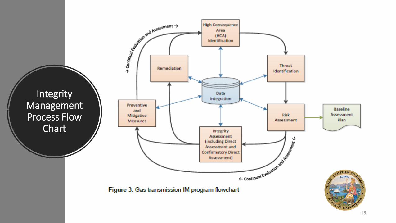
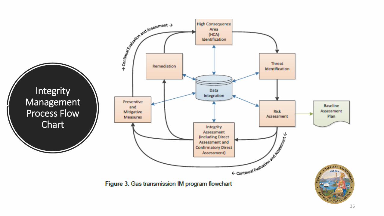
Integrity Management Process Flow
Chart
3
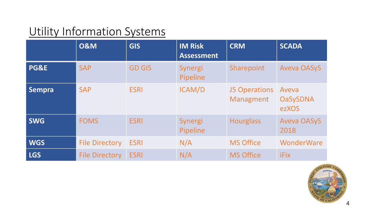
Utility Information SystemsO&M GIS IM Risk
AssessmentCRM SCADA
PG&E SAP GD GIS SynergiPipeline
Sharepoint Aveva OASyS
Sempra SAP ESRI ICAM/D J5 Operations Managment
AvevaOaSySDNAezXOS
SWG FOMS ESRI SynergiPipeline
Hourglass Aveva OASyS2018
WGS File Directory ESRI N/A MS Office WonderWare
LGS File Directory ESRI N/A MS Office iFix
4
SoCal Gas Data
Architecture
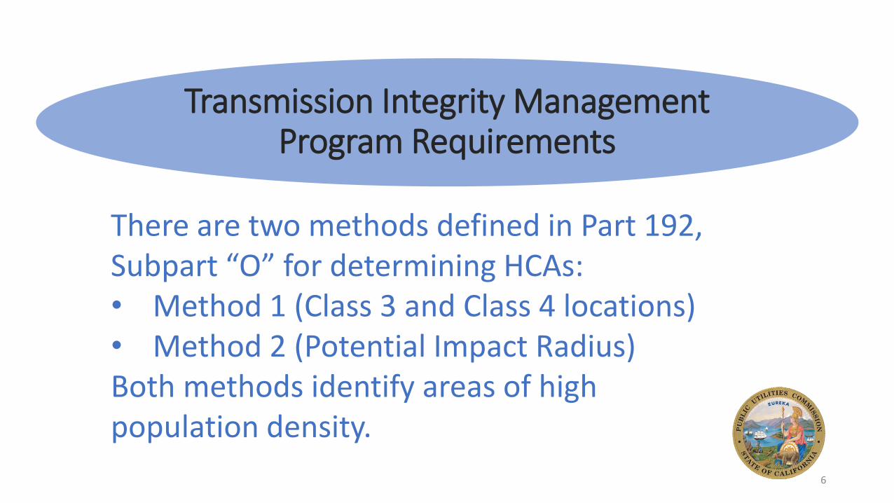
Part 192.917 Additional ThreatsTransmission Integrity Management
Program Requirements
There are two methods defined in Part 192, Subpart “O” for determining HCAs:• Method 1 (Class 3 and Class 4 locations)• Method 2 (Potential Impact Radius)Both methods identify areas of high population density.
6
Integrity Management Process Flow
Chart
7
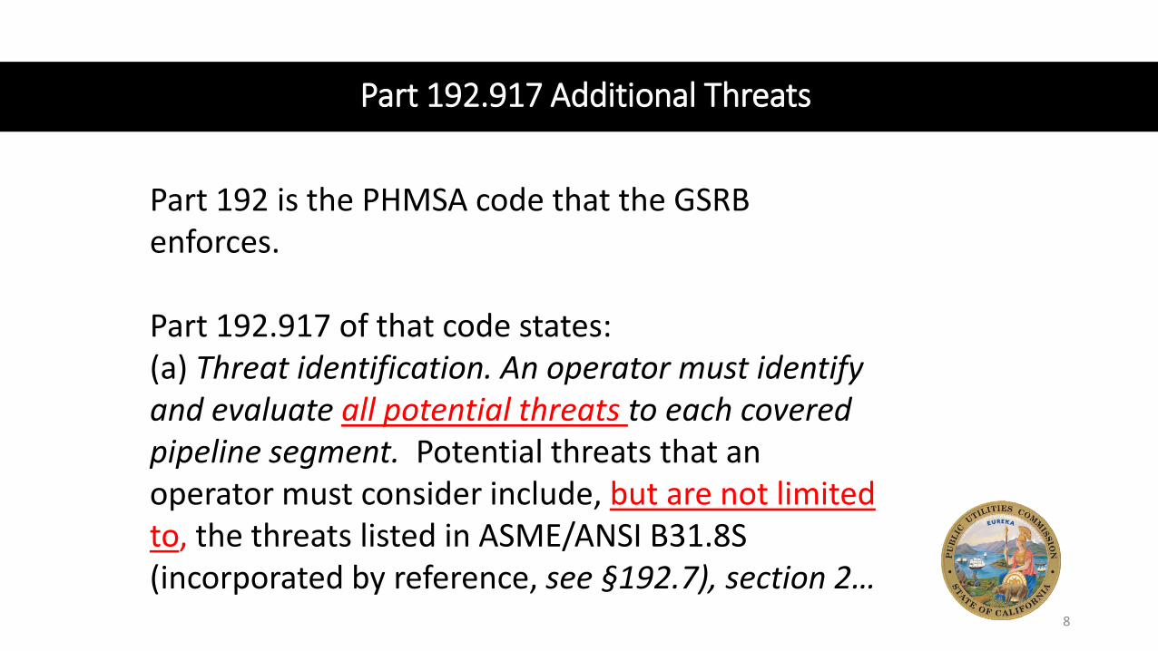
Part 192.917 Additional Threats
Part 192 is the PHMSA code that the GSRB enforces.
Part 192.917 of that code states:(a) Threat identification. An operator must identify and evaluate all potential threats to each covered pipeline segment. Potential threats that an operator must consider include, but are not limited to, the threats listed in ASME/ANSI B31.8S (incorporated by reference, see §192.7), section 2…
8
Threats Defined by B31.8S-2004
Time Dependent
External Corrosion
Internal Corrosion
Stress Corrosion Cracking
9
Threats Defined by B31.8S-2004
Stable
Manufacturing Defects
Construction Defects
Equipment
(i.e., Pressure Regulation)
10
Threats Defined by B31.8S-2004
Time Independent
Third Party Damage
Incorrect Operations
Weather Related andOutside Force
11
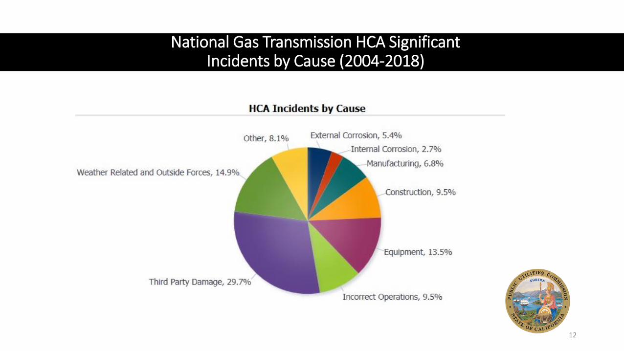
National Gas Transmission HCA Significant Incidents by Cause (2004-2018)
12
Each Threat is defined in B31.8S-2004
Example:The construction threat is defined in B31.8S-2004, Appendix A.5.1 as:pipe girth weld, fabrication weld, wrinkle bend or buckle, stripped threads, broken pipe, or coupling...
13
Data Gathering and Integration is also Defined in B31.8S-2004
Example:For the construction threat, the following data must be gathered:(a) pipe material(b) wrinkle bend identification(c) coupling identification(d) post-construction coupling reinforcement(e) welding procedures(f) post-construction girth weld reinforcement(g) NDT information on welds
14
Data Gathering and Integration is also Defined in B31.8S-2004
Example:For the construction threat, the following data must be gathered:(h) hydrostatic test information(i) pipe inspection reports (bell hole)(j) potential for outside forces (see para. A9)(k) soil properties and depth of cover for wrinkle bends(l) maximum temperature ranges for wrinkle bends (m) bend radii and degrees of angle change for wrinkle bends(n) operating pressure history and expected operation,
including significant pressure cycling and fatigue mechanism
15
Integrity Management Process Flow
Chart
16
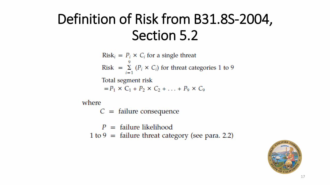
Definition of Risk from B31.8S-2004, Section 5.2
17
Risk Assessment
Methods Defined
by B31.8S-2004, Section
5.5
• Subject Matter Expert (SME) Approach
• Relative Risk Model
• Scenario Based Model
• Probabilistic Risk Model
18
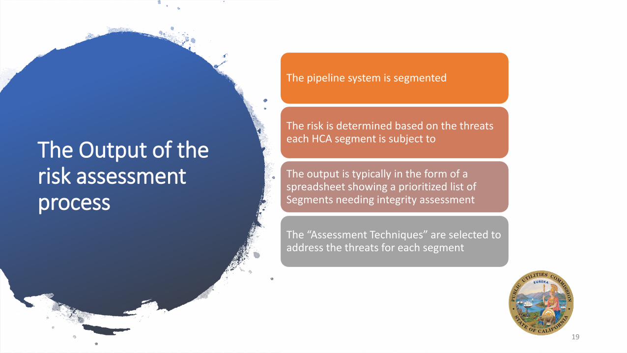
The Output of the risk assessment process
The pipeline system is segmented
The risk is determined based on the threats each HCA segment is subject to
The output is typically in the form of a spreadsheet showing a prioritized list of Segments needing integrity assessment
The “Assessment Techniques” are selected to address the threats for each segment
19
Integrity Management Process Flow
Chart
20
Integrity Assessment Techniques Allowed by
Part 192.937(c)
• In-Line-Inspection Tools (a.k.a., Smart PIGs)
• Pressure Testing per Part 192, Subpart J
• Direct Assessment for the threats of External Corrosion, Internal Corrosion and Stress Corrosion Cracking
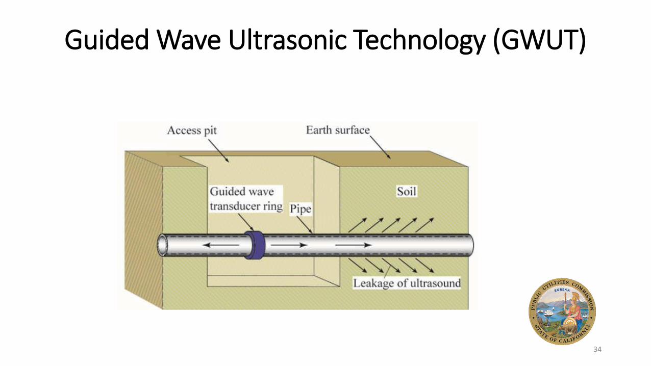
• Other Technology (i.e., Guided Wave Ultrasonic Technology, etc.)
21
Integrity Assessment Techniques Allowed by
Part 192.937(c)
There are advantages and disadvantages to each of the four integrity assessment technique from the previous page.
22
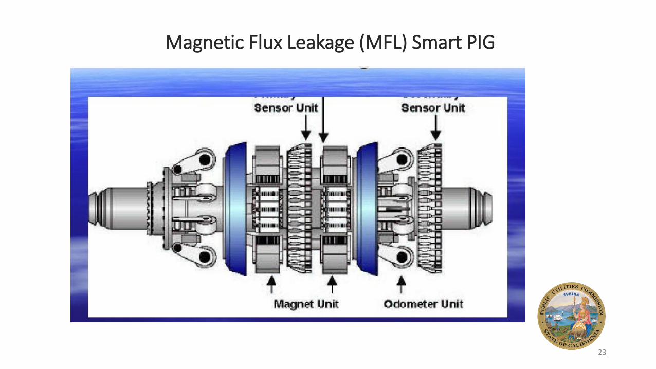
Magnetic Flux Leakage (MFL) Smart PIG
23
MFL Principle of Operation
24
A Diagram Illustrating the movement of a Smart PIG
25
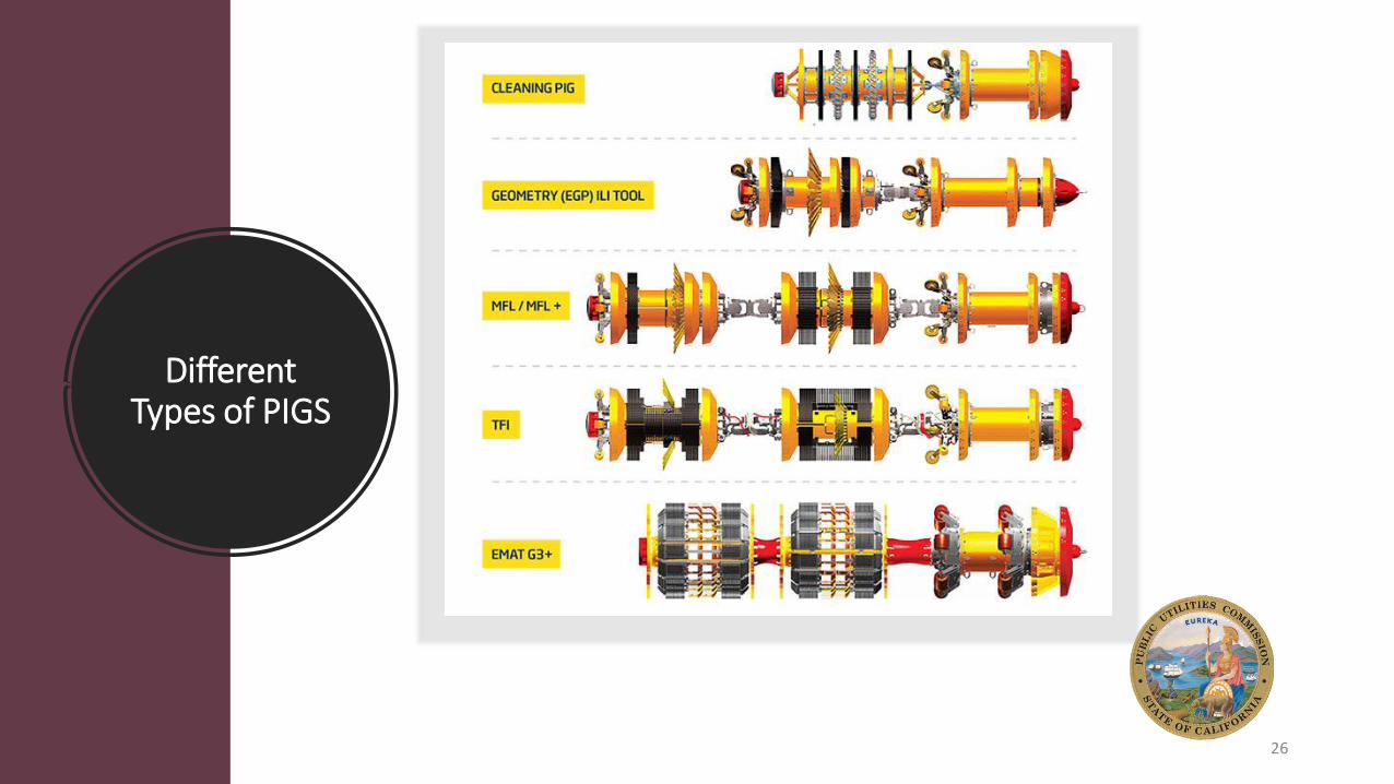
Different Types of PIGS
26
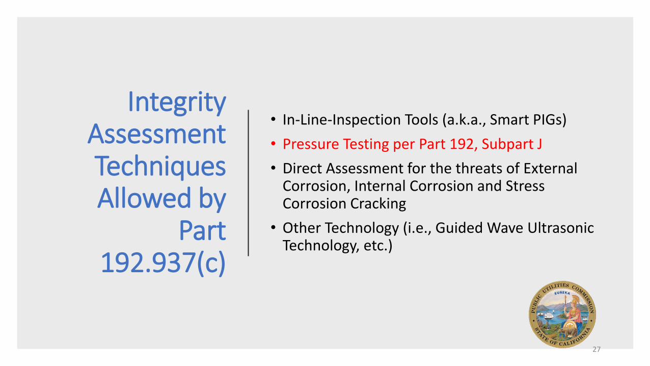
Integrity Assessment Techniques Allowed by
Part 192.937(c)
• In-Line-Inspection Tools (a.k.a., Smart PIGs)
• Pressure Testing per Part 192, Subpart J
• Direct Assessment for the threats of External Corrosion, Internal Corrosion and Stress Corrosion Cracking
• Other Technology (i.e., Guided Wave Ultrasonic Technology, etc.)
27
Pressure Testing a Segment of Pipe
28
Integrity Assessment Techniques Allowed by
Part 192.937(c)
• In-Line-Inspection Tools (a.k.a., Smart PIGs)
• Pressure Testing per Part 192, Subpart J
• Direct Assessment for the threats of External Corrosion, Internal Corrosion and Stress Corrosion Cracking
• Other Technology (i.e., Guided Wave Ultrasonic Technology, etc.)
29
Direct Assessment for three threatsExternal Corrosion Direct Assessment (ECDA) is defined as: ECDA is a four-step process that combines preassessment, indirect inspection, direct examination, and post assessment to evaluate the threat of external corrosion to the integrity of a pipeline.
Internal Corrosion Direct Assessment (ICDA) is defined as:A process an operator uses to identify areas along the pipeline where fluid or other electrolyte introduced during normal operation or by an upset condition may reside, and then focuses direct examination on the locations in covered segments where internal corrosion is most likely to exist…
Stress Corrosion Cracking Direct Assessment (SCCDA) is defined as:A process to assess a covered pipe segment for the presence of SCC primarily by systematically gathering and analyzing excavation data for pipe having similar operational characteristics and residing in a similar physical environment.
30
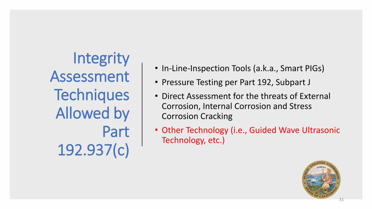
Integrity Assessment Techniques Allowed by
Part 192.937(c)
• In-Line-Inspection Tools (a.k.a., Smart PIGs)
• Pressure Testing per Part 192, Subpart J
• Direct Assessment for the threats of External Corrosion, Internal Corrosion and Stress Corrosion Cracking
• Other Technology (i.e., Guided Wave Ultrasonic Technology, etc.)
31
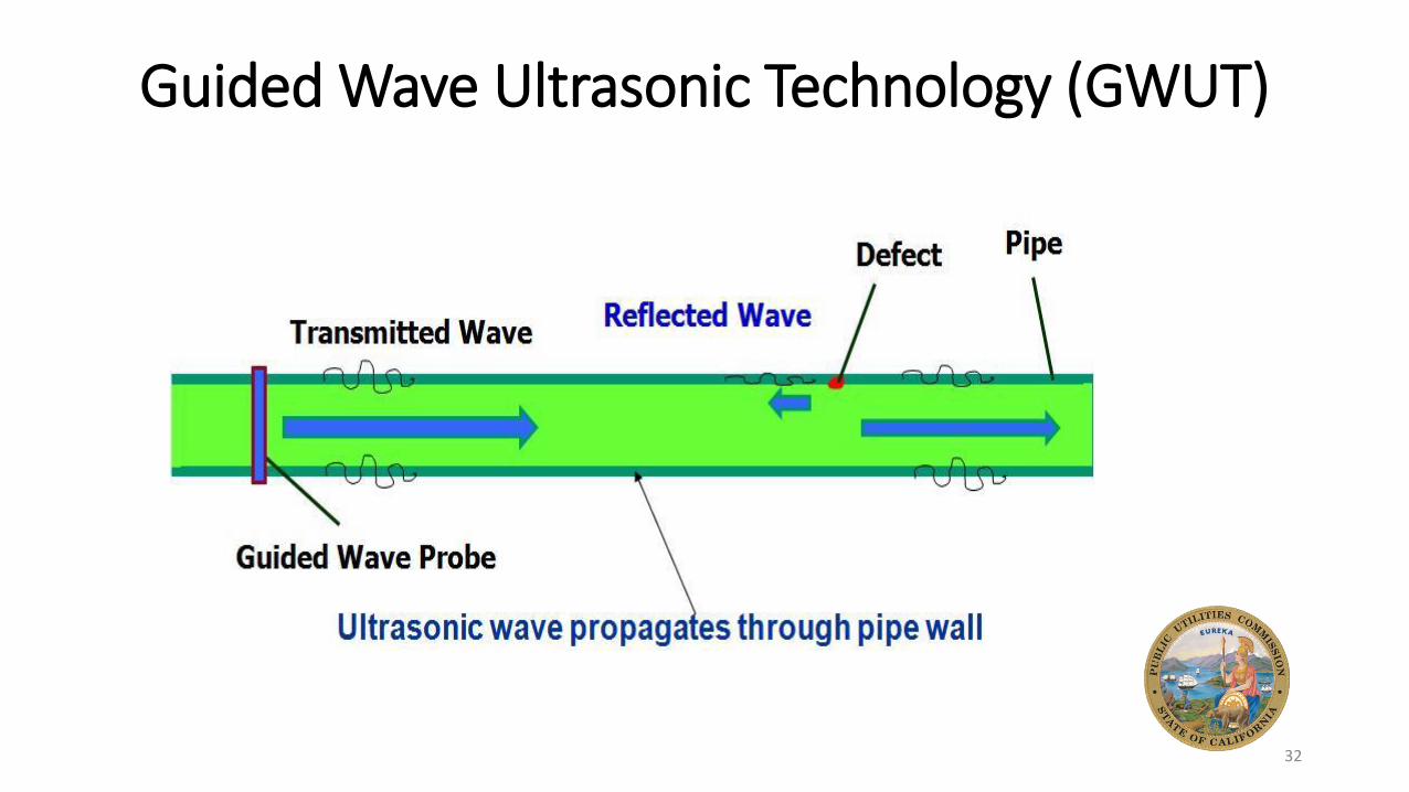
Guided Wave Ultrasonic Technology (GWUT)
32
Guided Wave Ultrasonic Technology (GWUT)
33
Guided Wave Ultrasonic Technology (GWUT)
34
Integrity Management Process Flow
Chart
35
Remediation (i.e., Repair)
and/orPreventative/
Mitigative Measures
• The output of the integrity assessments are locations along the pipeline that need further investigation (i.e., direct examinations) or repair
• Depending on the root cause(s) of the pipeline issues that need repair, addition preventative or mitigative measure may be chosen to reduce risk.