*Actual product may vary slightly Please carefully read and save these instructions before attempting to assemble, maintain, install, or operate this product. Observe all safety information to protect yourself and others. Failure to observe the instructions may result in property damage and/or personal injury. Please keep instructions for future reference. For warranty purchases, please keep your dated proof of purchase. File or attach to the manual for safe keeping. For Customer Service, Call 1-800-348-5004 or e-mail [email protected]20158 / 20160 04/2017 * For customers in high altitudes areas, please call 1-800-348-5004 if the engine can not be started or performed poorly. 57CC CHAINSAW 20160: 57CC 22” CHAINSAW 20158: 57CC 18” & 22” CHAINSAW
Transcript
*Actual product may vary slightly
Please carefully read and save these instructions before attempting to assemble, maintain, install, or operate this product.
Observe all safety information to protect yourself and others. Failure to observe the instructions may result in property
damage and/or personal injury. Please keep instructions for future reference.
For warranty purchases, please keep your dated proof of purchase. File or attach to the manual for safe keeping.
* For customers in high altitudes areas,please call 1-800-348-5004 if the enginecan not be started or performed poorly.
57CC CHAINSAW
20160:57CC 22” CHAINSAW
20158:57CC 18” & 22” CHAINSAW
CALIFORNIA PROPOSITION 65WARNING: You can create dust when you cut, sand, drill or grind materials such as wood,paint, metal, concrete, cement, or other masonry. This dust often containschemicals known to cause cancer, birth defects, or other reproductive harm.Wear protective gear.
WARNING: This product or its power cord may contain chemicals, including lead, known to the State of California to cause cancer and birth defects or other reproductiveharm. Wash hands after handling.
IMPORTANT!When using equipment, a few safety precautions must be observed to avoidinjuries and damage. Please read the complete operating manual with duecare. Keep this manual in a safe place, so that the information is availableat all times. If you give the equipment to any other person, give themthese operating instructions as well. We accept no liability for damageor accidents which arise due to non-observance of these instructionsand the safety information herein.
PLEASE SAVE THIS OWNERS MANUAL AND READ BEFORE EACH USE. This manual will explain how to use the solar panel kit safely and effectively.Please read and follow these instructions and precautions carefully.
IMPORTANT SAFETY INSTRUCTIONS
1-800-348-50042
SAFETY WARNINGSIMPORTANT!
READ CAREFULLY BEFORE USE.
KEEP FOR FUTURE REFERENCE.
1. Petrol powered chain saw safety warnings
1. This product is dangerous if used carelessly or incorrectly and can causeserious or even fatal injuries.
2. Read all instructions carefully. When using petrol powered products, alwaysfollow stated safety precautions to reduce the risk of serious personal injuryand/or damage to the product.
3. The product should only be operated by those who have read and understoodall safety and operating instructions in this manual. Local regulations canrestrict the age of the operator.
4. Keep your work area free from pets, animals, children and bystanders.
5. Follow instructions for lubricating, chain tensioning and changing accessories.Improperly tensioned or lubricated chain may either break or increase thechance for kickback. It may cause the chain to snap, which could lead toserious or even fatal injuries.
6. Running this product in a confined or badly ventilated area can result in deathdue to asphyxiation or carbon monoxide poisoning. The product is for outdooruse only.
7. Take extreme care in wet and freezing weather conditions. Do not work inrain, windy or stormy weather.
8. Do wear a face and breathing mask. The use of this product can generateexhaust gases, lubrication oil mist and saw dust containing chemicals knownto cause respiratory damage.
9. Do use safety steel toe capped footwear, sturdy cut retardant snug-fittingprotective clothing, protective gloves, eye, hearing and head protectiondevices.
10. Do always visually check the product before use.
11. Do not attempt to tackle any job that you are not adequately trained for.
12. Do not allow other persons to be near when starting or cutting with theproduct.
13. Keep bystanders and animals at least 15 metres out of the work area.
1-800-348-50043
14. Do not operate the product if it has faulty safety equipment or damaged parts!
15. Do not under any circumstances modify the product. Modifications can resultin serious personal injury or death.
16. Do not start cutting until you have a clear work area, secure footing, and aplanned retreat path from the falling tree.
17. All product servicing & maintenance, other than the items listed in the usermanual, safety and maintenance instructions, should be performed by anauthorised service centre.
18. A first time user should have practical instruction in the use of the product andprotective equipment from an experienced operator.
19. National regulation can restrict the use of the product.
2. Clothing and protective equipment
1. Do secure long hair so that it is above shoulder level.
2. Do not wear loose fitting clothing or jewelry as this could be drawn into theengine, catch the chain or undergrowth.
3. Use the following safety clothing and protective equipment when operatingthe product:
Helmet with visor and neck guard
Hearing protectors
Breathing mask
Gloves with approved saw protection
Protective leggings with approved saw protection
Slip-resistant steel toe cap boots with approved saw protection
First Aid kit in case of injury
3. Fuel handling
1. Always switch the product off, disconnect the spark plug connector and let theproduct cool down, before refuelling it. Fuel and fuel vapour are highlyflammable. Take care when handling fuel. Never smoke when you arerefuelling the product. Do not refuel the product, if there is an open fire in thevicinity!
1-800-348-50044
2. Always use suitable aids such as funnels and filler necks. Do not spill any fuelon the product or its exhaust system. There is a risk of ignition. Removespilled fuel carefully from all parts of the product. Any residue which may bepresent must have completely volatilised, before the product is put intooperation!
3. Never refuel indoors.
4. Never use the product in environments where there is a risk of explosion.Exhaust gases and fuel fumes are noxious. Fuel fumes can ignite.
5. Never breathe in any fuel fumes, when you are refuelling the product. Neverfill the tank in enclosed spaces, such as basements or sheds. There is a riskof poisoning and explosion!
6. Avoid skin contact with petrol.
7. Do not eat or drink, while you are refuelling the product. If you haveswallowed petrol or oil, or if petrol or oil has got into your eyes, then seek theadvice of a doctor immediately.
8. Close the tank lid immediately after filling the tank. Make sure that it isproperly closed.
9. Never use the product without an air filter.
10. Fuel vapour pressure may build up inside the fuel tank depending on the fuelused, weather conditions and the tank venting system. To reduce the risk ofburns and other personal injuries, remove the fuel cap carefully to allow anypressure build up to release slowly.
11. Be aware of fire risks, explosion and inhalation risks.
12. Do not smoke while operating the product, handling fuel or near fuel.
13. Ensure the spark plug lead is secured; a loose lead may cause electricalarcing that could ignite combustible fumes and cause a fire or explosion.
14. Check regularly for leaks from the fuel cap and fuel lines.
15. Use caution when handling fuel. To avoid any accidental fires, move theproduct at least 3 metres (10’) from the fuelling point before starting theengine.
16. Tighten the fuel cap thoroughly after refilling the fuel tank.
17. Do not operate the product if it is leaking fuel. Do not remove the fuel tankcap while the engine is running.
18. Use only an approved container.
1-800-348-50045
19. Do not store cans of fuel or refill the fuel tank in any place where there is aboiler, stove, wood fire, electrical sparks, welding sparks, or other sources ofheat or fire which might ignite the fuel.
20. If any fuel spillage occurs during refuelling, use a dry rag to wipe up spills andallow remaining fuel to evaporate before turning the engine on again.
21. If you have spilt fuel on yourself or on your clothes, change your clothes andwash any part of your body that has come in contact with fuel before turningthe engine on again.
22. If fuel is ignited, put out the fire with a dry powder fire extinguisher.23. If the fuel tank is drained, this should be done outdoors.
4. Getting startedLONGER TIME UNUSED MACHINE RESTARTINGUnused machine be in storage for longer than 90days, the ignition coil be not damaged,it’s only carburetor issue. Please follow these Instructions to restart the machine.
1. Check either the fuel pipe aging or cracking, if any, easy to buy new one forreplacement at local store.
2. Check either the fuel pipe joint of carburetor loosening or aging, if any, cutthe pipe joint a little bit to rejoin as well.
3. Please pull the starting rope 5-8 times before fuel refilling to the carburetoris in an operating state.
4. Refilling the fuel and then restart the machine according to the cold start mode5. Do not operate the product indoors, it produces poisonous exhaust fumes whilst
the engine is running and may be colorless and odourless.6. Do not wrap the recoil starter rope around your hand whilst starting the product.
This may result in injuries to your hand or fingers.7. Do keep handles dry, clean, and free from oil and grease. Greasy, oily handles
are slippery causing loss of control.8. Do not operate the product with a slack chain. A slack chain may jump off the
guide bar and cause serious or even fatal injury.9. Do not operate the product with one hand! Serious injury to the operator or
bystanders may result from one handed operation.10. Keep all parts of the body away from the saw chain when the chain saw is
operating. Before you start the chain saw, make sure the saw chain is notcontacting anything and free from obstructions. A moment of inattention whileoperating chain saws may cause entanglement of your clothing or body withthe saw chain.
11. Do shut off the engine before setting the product down.12 . Before using the product and after any impact or dropping, check for signs of wear or damage and repair as necessary.5. Operation1. When sawing, ensure the product does not touch any foreign materials such
as rocks, fences, nails etc. Such objects may be flung out and could result indamage to the product or serious personal injury or even death.
2. Never operate the product on a ladder or other insecure support.
1-800-348-50046
3. If the chain jams in the cut: STOP THE ENGINE. Do not try to pull theproduct free. Use a lever to open the cut and free the chain. Failure to do socould result in serious injuries or death.
4. Do only cut with the engine at high speeds.
5. Do use extreme caution when cutting small size bushes and saplings.Slender material may catch the saw chain and whip toward you or put you offbalance.
6. Do operate the product only in well ventilated areas.
7. Do not operate the product with one hand! This product is intended for twohanded use only, with your right hand on the rear handle and your left handon the front handle. You cannot control reactive forces and you may losecontrol of the saw, which can result in the skating or bouncing of the bar andchain along the limb or log.
8. Do not operate the product if you are tired.
9. Do not operate the product if you have any medical conditions that might beaggravated by strenuous work. Check with your doctor before operating thisproduct.
10. Do not operate the product under the influence of drugs, alcohol ormedication.
11. Do not touch the exhaust during use - IT GETS VERY HOT.
12. Do not operate a product that is damaged, improperly adjusted, or notcompletely and securely assembled. Be sure that the saw chain stopsmoving when the throttle trigger is released.
13. Do not operate this product in a tree unless you have been specificallytrained to do so. Operation of the product while up in a tree may result inpersonal injury.
14. Do not operate your product near or around flammable liquids or gases.
15. Do not smoke whilst operating the product.
16. Do not lock the product over fixed stands.
17. Do not grip the handles with constant or excessive pressure; this willincrease the feeling of vibration and the risk of ‘whitefinger’ disease.
18. Do not over reach when operating the product or cut above shoulder height.
19. Do not operate the product if it is leaking fuel or chain oil.
20. When cutting a limb (branch) that is under tension, be alert for spring back sothat you will not be struck when the tension in the wood fibres is released.
1-800-348-50047
21. Always keep proper footing and operate the chain saw only when standingon fixed, secure and level surface. Slippery or unstable surfaces such asladders may cause a loss of balance or control of the chain saw.
22. Cut wood only. Do not use the product for purposes not intended. Forexample: do not use chain saw for cutting plastic, masonry or non-woodbuilding materials. Use of the chain saw for operations different thanintended could result in a hazardous situation.
6. Transport and storage
Do ensure the engine is off and engage the chain brake before transporting 1.the product.
Do carry the product with the engine stopped, the guide bar and saw chain to2.the rear, and the exhaust away from your body.
Do use the guide bar cover and ensure that is fitted to the product during3.transportation or storage.
Only carry the product in a horizontal position. Grip the front handle in a4.manner that the product is balanced horizontally.
Keep the hot exhaust away from your body and the saw chain behind you.5.
Correctly secure your product when transporting in a vehicle to prevent6.turnover, fuel spillage and damage to the product.
Always store the product and fuel so that there is no risk of leakages or fumes7.coming into contact with sparks or naked flames from electrical equipment,electric motors, relays/switches, boilers etc.
For longer periods of storage or transportation the fuel and chain oil tanks8.must be emptied. Dispose of waste oil and fuel at a local petrol station, localauthority centre or where facilities exist.
Do store fuel in an approved container designed for that purpose.9.
Do ensure that the product is cleaned and that a complete service is10.conducted before any long-term storage.
7. Causes and operator prevention of kickback
Kickback may occur when the nose or tip of the guide bar touches an object, or when the wood closes in and pinches the saw chain in the cut.
Tip contact in some cases may cause a sudden reverse reaction, kicking the guide bar up and back towards the operator.
1-800-348-50048
Pinching the saw chain along the top of the guide bar may push the guide bar rapidly back towards the operator.
Either of these reactions may cause you to lose control of the saw which could result in serious personal injury. Do not rely exclusively upon the safety devices built into your saw. As a chain saw user, you should take several steps to keep your cutting jobs free from accident or injury.
Kickback is the result of tool misuse and/or incorrect operating procedures or conditions and can be avoided by taking proper precautions as given below:
Maintain a firm grip, with thumbs and fingers encircling the chain saw 1.handles, with both hands on the saw and position your body and arm to allow you to resist kickback forces. Kickback forces can be controlled by the operator, if proper precautions are taken. Do not let go of the chain saw.
Do not overreach and do not cut above shoulder height. This helps2.prevent unintended tip contact and enables better control of the chain saw inunexpected situations.
Only use replacement bars and chains specified by the manufacturer.3.Incorrect replacement bars and chains may cause chain breakage and/orkickback.
Follow the manufacturer’s sharpening and maintenance instructions for4.the saw chain. Decreasing the depth gauge height can lead to increasedkickback.
8. Vibration and noise reduction
To reduce the impact of noise and vibration emission, limit the time of operation, use low-vibration and low-noise operating modes as well as wear personal protective equipment.
Take the following points into account to minimise the vibration and noise exposure risks:
1. Only use the product as intended by its design and these instructions.
2. Ensure that the product is in good condition and well maintained.
3. Use correct attachments for the product and ensure they are in goodcondition.
4. Keep tight grip on the handles/gripping surface.
5. Maintain this product in accordance with these instructions and keep it welllubricated (where appropriate).
1-800-348-50049
6. Plan your work schedule to spread any high vibration tool use across a longerperiod of time.
7. Prolonged use of the product exposes the user to vibrations that can cause arange of conditions collectively known as hand-arm vibration syndrome(HAVS) e.g. fingers going white; as well as specific diseases such as carpaltunnel syndrome.
- To reduce this risk when using the product, always wear protectivegloves and keep your hands warm.
- The symptoms of HAVS include any combination of the following:Tingling and numbness in the fingers; Not being able to feel thingsproperly; Loss of strength in the hands; Fingers going white (blanching)and becoming red and painful on recovery (particularly in the cold andwet, and probably only in the tips at first). Seek medical adviceimmediately if such symptoms are experienced.
9. Emergency
Familiarise yourself with the use of this product by means of this instruction manual. Memorise the safety directions and follow them to the letter. This will help to prevent risks and hazards.
1. Always be alert when using this product, so that you can recognise andhandle risks early. Fast intervention can prevent serious injury and damageto property.
2. Stop the engine and unplug the spark plug connector if there aremalfunctions. Have the product checked by a qualified professional andrepaired, if necessary, before you operate it again.
3. In case of fire stop the engine and unplug the spark plug connector.Take fire-extinguishing measures immediately if the product switch is nolonger accessible.
WARNING! Never use water to extinguish a product on fire. Burning fuel must be extinguished with special extinguishing agents. We recommend that you keep a suitable fire extinguisher within reach in your work area!
1-800-348-500410
10. Residual risks
Even if you are operating this product in accordance with all the safety requirements, potential risks of injury and damage remain. The following dangers can arise in connection with the structure and design of this product:
1. Health defects resulting from vibration emission if the product is being usedover long periods of time or not adequately managed and properly maintained.
2. Injuries and damage to property due to broken attachments or the suddenimpact of hidden objects during use.
3. Danger of injury and property damage caused by flying objects.
4. Prolonged use of this product expose the operator to vibrations and mayproduce ‘whitefinger’ disease. In order to reduce the risk, please wear glovesand keep your hands warm. If any of the ‘whitefinger’ symptoms appear, seekmedical advice immediately. ‘Whitefinger’ symptoms include: numbness, lossof feeling, tingling, pricking, pain, loss of strength, changes in skin color orcondition. These symptoms normally appear in the fingers, hands or wrists.The risk increases at low temperatures.
WARNING! This product produces an electromagnetic field during operation! This field may under some circumstances interfere with active or passive medical implants! To reduce the risk of serious or fatal injury, we recommend persons with medical implants to consult their doctor and the medical implant manufacturer before operating this product!
11. Symbols
On the product, the rating label and within these instructions you will find among others the following symbols and abbreviations. Familiarise yourself with them to reduce hazards like personal injuries and damage to property.
kW Kilowatt
cm³ Cubic centimetre
min-1 or /min per minute
mm Millimetre
kg Kilogram
l Litre
dB(A) Decibel (A-rated)
1-800-348-500411
m/s² Metres per second squared
Lock / to tighten or secure
Unlock / to loosen
Note / Remark.
Caution / Warning.
Read the instruction manual.
Wear a helmet, safety goggles and hearing protection.
Wear protective gloves.
Wear a dust mask.
Wear respiratory protection.
Wear protective, slip-resistant footwear.
Wear tight-fitted protective clothes.
Use appropriate protection for foot-leg and hand-arm.
1-800-348-500412
Do not expose the product to rain or wet conditions.
Open flames in the work area, around the product and in the vicinity of flammable materials are prohibited!
Do not smoke in the work area, around the product and in the vicinity of flammable materials!
Risk of fire / flammable materials
Hot surface, do not touch! High temperatures on the product’s surfaces and structural parts that could cause burns, if they are touched. The product can also stay hot for a longer period of time after operation!
This product produces noxious exhaust fumes. If the product is used improperly, these fumes can lead to poisoning, a loss of consciousness or death!
Noxious exhaust fumes; do not operate or start the product in indoor rooms!
Switch the product off and disconnect the spark plug connector before assembly, cleaning, adjustments, maintenance, storage and transportation.
Kickback! Tip contact may cause the guide bar to move suddenly upward and backwards what may cause serious injury to user.
Contact of the guide bar tip with any object should be avoided.
Always use the product with two hands. Do not use one hand when operating the product.
1-800-348-500413
Objects thrown by the product could hit the user or other bystanders. Always ensure that other people and pets remain at a safe distance from the product when it is in operation. In general, children must not come near the area where the product is.
Keep a distance of at least 15 m.
Only use petrol/oil mixture with a ratio of 40:1. Do not use any other mixture ratio. Always switch the product off and let it cool down, before refuelling it.
Choke – CLOSE position
Choke – OPEN position
Ignition switch positions. Stop the engine
H H - Set the max. engine speed
L L - Set the min. engine speed
Engine manual start; recoil starter
Correct direction of cutting-teeth
Chain oil fill
Indication of chain oil adjuster screw; location: bottom
Chain brake (the symbol shows the position in which the brake is released)
Guaranteed sound power level value in dB
1-800-348-500414
15m
PRODUCT DESCRIPTION
1 2 3 4 5
6
7 8 8a
9101112 13
14
15
16
1718
2122
1920
23242526272829
8b
1-800-348-500415
8a
1. Rear handle
2. Throttle interlock
3. Throttle trigger
4. Air filter casea. Fixation knob*b. Cover*c. Air filter*
Please check the completeness of the delivery and ensure that all parts are free from any transport-related damage or any damage in general. Please contact the supplier from whom you purchased the product should there be any parts missing or damaged.
ACCESSORIES (NOT SUPPLIED)
Suitable personal protective equipment
Petrol and engine oil
Funnel with filter
Lubricant for saw chain
Fuel collecting container
Lubrication oil/grease
Air filter oil
Soft cloth
Suitable slot head screwdriver
Sharpening set (chain file)
TECHNICAL DATA
1. General
Dimensions 540 x 470 x 305 mm
Machine mass (without guide bar and chain, empty tanks and in normal operating configuration) approx. 5.7 kg
Machine mass (with guide bar and chain, empty tanks and in normal operating configuration) 20160: approx. 6. 68 kg
Sound pressure level at operator’s position LpA 104.15 dB(A)
Uncertainty KpA 2.5 dB(A)
Measured sound power level LWA 113.88 dB(A)
Uncertainty KWA 2.5 dB(A)
Guaranteed sound power level LWA 117 dB(A)
5. Vibration values
Front handle, afront hv,eq 7.234 m/s²
Rear handle, arear hv,eq 9.528 m/s²
Uncertainty K 1.5 m/s²
The sound values have been determined according to noise test code given in EN ISO 11681-1, using the basic standard ISO 22868.
The noise figures quoted are emission levels and are not necessarily safe working levels. Factors that influence the actual level of exposure of work-force
i
nclude the characteristics of the work room, the other sources of noise, etc. i.e.
t
he number of products and other adjacent processes, and the length of time for which an operator is exposed to the noise. Also the permissible exposure level can vary from country. This information, however, will enable the user of the product to make a better evaluation of the hazard and risk.
Wear hearing protection! The sound intensity level for the operator may exceed 80 dB(A) and ear protection measures are necessary!
The declared vibration value has been measured in accordance with a standard
t
est method (according to basic standard ISO 22867) and may be used for comparing one product with another. The declared vibration value may also be used in a preliminary assessment of exposure.
This product may cause hand-arm vibration syndrome if its use is not adequately managed.
WARNING! Depending on the actual use of the product the vibration values can differ from the declared total! Adopt proper measures to protect yourself against vibration exposures! Take the whole work process including times the product is running under no load or switched off into consideration!
Proper measures include among others regular maintenance and care of the product and cutting attachments, keeping hands warm, periodical breaks and proper planning of work processes!
INTENDED USE
This petrol chain saw is designated with a rated power output of 2.5 KW.The product is intended for cutting logs and limbs with a thickness of max. 480mm.
It must not be used for cutting other materials, such as plastic, stone, metal, wood that contains foreign objects, or materials that are harmful to health. This product should not be used outside of domestic premises e.g. for cutting firewood in forested areas.
The product may only be used with the guide bar/saw chain combination stated within these instructions. The use of other types or sizes is not allowed.
With this product vertical and horizontal cuts can be performed. Longitudinal sections may only be cut by professionals.
For safety reasons it is essential to read the entire instruction manual before first operation and to observe all the instructions therein.
This product is intended for private domestic use only, not for any commercial trade use. It must not be used for any purposes other than those described.
ASSEMBLY
1. Unpack
1. Unpack all parts and lay them on a flat, stable surface.
2. Remove all packing materials and shipping devices if applicable.
3. Make sure the delivery contents are complete and free of any damage. If youfind that parts are missing or show damage do not use the product butcontact your dealer. Using an incomplete or damaged product represents ahazard to people and property.
4. Ensure that you have all the accessories and tools needed for assembly andoperation. This also includes suitable personal protective equipment.
WARNING! The product and the packaging are not children’s toys! Children must not play with plastic bags, sheets and small parts! There is a danger of choking and suffocation!
WARNING! The product must be fully assembled before operation! Do not use a product that is only partly assembled or assembled with damaged parts!
Follow the assembly instructions step-by-step and use the pictures provided as a visual guide to easily assemble the product!
Disconnect the spark plug connector (19) from the spark plug! Reconnect it after assembly!
Always wear protective gloves during assembly!
NOTE: Take care of small parts that are removed during assembly or when making adjustments. Keep them secure to avoid loss.
2. Chain and guide bar
Assemble the guide bar (8) and saw chain (7) before operation.
Use only the guide bar (8) and saw chain (7) according to the technical parameter of this product.
WARNING! Always use a saw chain designed as “low-kickback” or a saw chain which meets the low-kickback requirements! Astandard saw chain (a chain which does not have the kickback reducing guard links) should only be used by an experienced professional operator!
Nevertheless, a low-kickback saw chain does not completely eliminate kickback! A low-kickback or “safety” chain should never be regarded as complete protection against injury! Therefore always use a low-kickback saw chain in conjunction with other kickback protection devices such as the front hand guard!
WARNING! Move the front guard (6) fully backward to disengage chain brake.
1. Place the product on a suitable flat surface.
1-800-348-500422
2. Pull the front hand guard (6) back toward the front handle (5) to disengagethe chain break, if necessary.
3. Loosen the retaining nuts (9) with the multi tool (32) and remove themtogether with the cover (11) (Fig. 1).
Fig. 1
4. Place the slot in the guide bar (8) over the bolts (13). Ensure to fit the guidebar with the saw chain ‘cutter’ symbol at the top of the bar (Fig. 2).
Fig. 2
5. Push the guide bar (8) to the left towards the drive sprocket (18) (behind theclutch (17)) (Fig. 3).
6
3211
9
813
6
1-800-348-500423
Fig. 3
WARNING! The direction of the saw chain ‘cutters’ must be as indicated by the symbol and arrow on the guide bar!
6. Place the saw chain (7) over the drive sprocket (18) (behind the clutch (17))and fit around the guide bar (8). Make sure the saw chain is placed above thechain catcher (16) (Fig. 4).
Fig. 4
7. The saw chain movement is as indicated by the arrow (Fig. 5). Make sure thechain is properly placed over the sprocket wheel (8b) of the guide bar (8).
8. Pull the guide bar (8) carefully towards the right to tighten the saw chain (7)(Fig. 5).
8
1718
7 81718
16
1-800-348-500424
Fig. 5
9. Refit the cover (11). If necessary, turn the tension screw (10) clockwise oranticlockwise with the multi tool (32) to adjust the tension pin (10a) until itreaches a position where it can be inserted into the tension hole (8c) (Fig. 6).
Fig. 6
10. Secure the cover (11) with the retaining nuts (9) (Fig. 7).
8b
87
10a
10
32
8c
11
1-800-348-500425
Fig. 7
NOTE: Fix the nuts finger tight only at this stage. The chain tension cannot be adjusted with the retaining nut tightened - they must be loosened first.
NOTE: The saw chain (7) has not yet been tensioned. Tension the chain as described under “Saw chain tensioning”. After operating the product for approximately one hour, adjust the chain tension again.
Saw chain tensioning
Always check the saw chain tension before use, after the first cuts and regularly during use. Upon initial operation, new chains can lengthen considerably. This is normal during the break-in period and the interval between future adjustments will lengthen quickly.
WARNING! Disconnect the spark plug connector before adjusting saw chain tension!
The cutting edges of the saw chain are sharp! Always wear protective gloves when handling chain!
Always maintain proper chain tension! A loose chain increases the risk of kickback! A loose chain may jump out of the guide bar groove! This may injure the operator and damage the chain! A loose chain will cause rapid wear to the chain, guide bar and sprocket!
Tensioning the chain too tightly will overload the engine and cause damage, and insufficient tension can cause chain derailing,
9
32
11
1-800-348-500426
whereas a correctly tightened chain provides the best cutting characteristics and prolonged working life! The chain life mainly depends upon sufficient lubrication and correct tensioning!
NOTE: The chain tension cannot be adjusted with the retaining nuts tightened - they must be loosened first.
1. Lift up the tip of the guide bar (8) and keep it there as you adjust the tension(Fig. 8).
Fig. 8
2. Turn the tension screw (10) clockwise until the chain ‘tie straps’ are justtouching the bottom edge of the guide bar (8) (Figs. 9, 10).
Fig. 9 Fig. 10
3. Lift up the tip of the guide bar (8) and tighten the retaining nuts (9).
4. Pull the saw chain (7) along the top of the guide bar (8) by hand from one endto the other, several times. The chain should feel tight but still move freely.
Tension test
1. Check the chain tension using one hand to lift the saw chain (7) against theweight of the product. The correct chain tension is achieved when the saw
8
32
10
8
1-800-348-500427
chain can be lifted by approximately 2 - 4 mm from the guide bar (8) in the centre (Figs. 11, 12).
Fig. 11 Fig. 12
2. Adjust the tension if you find that the chain saw is too loose or tight.
3. Chain lubrication
WARNING! The product is not filled with chain oil. It is essential to fill the product with chain oil before using it! Never operate the product without chain oil as this will result in extensive damage to the product!
Operating the saw chain dry or with too little chain oil will decrease cutting efficiency, shorten the product life span and cause rapid wear to the saw chain and guide bar from overheating!
Insufficient chain oil is evident by smoke or bar discoloration! Adequate lubrication of the saw chain during cutting operations is essential to minimise friction with the guide bar!
1. Place the product on a stable, level surface with the chain oil tank cap (29)facing upward. We recommend laying a non-flammable sheet under theproduct.
2. Unscrew and remove the oil tank cap (29) (Fig. 13).
Fig. 13
2932
1-800-348-500428
3. Fill suitable lubricant into the tank using a funnel fitted with a filter to avoiddebris entering the tank. Do not overfill and leave approximately 5 mm ofspace between the top of the oil and the inside edge of the tank to allow forexpansion (Fig. x).
NOTE: Use engine oil SAE#10W-30 all year round or SAE#30-#40 in summer and SAE#20 in winter.
Fig. 14
NOTE: Towards the end of the season, it is advisable to put only as much lubricant in the tank as you need for each cut, so that it is completely used up before you store the product.
4. Wipe up spilled lubricant with a soft cloth and refit the oil tank cap (29). Usethe multi tool (32) to tighten the cap properly.
NOTE: Always dispose of lubricant, used oil and objects contaminated with them in accordance with local regulations.
Checking
NOTE: Perform the following test before operating your product.
This product is equipped with an automatic oiling system! The oiling system automatically delivers the proper amount of oil to the bar and chain!
Checking the lubrication requires starting the engine. Before checking, the product must be fully assembled and all instructions must have been read.
1. Make sure the guide bar (8) and the saw chain (7) are in place when youcheck the oil delivery.
2. Start the engine; keep it running at medium power and check if the chain oil isdelivered as shown in the figure (Fig. 15).
1-800-348-500429
Fig. 15
3. Turn the adjustment screw (27) of the oiler on the bottom of the product toadjust the chain oil flow using a suitable slot head screwdriver (Fig. 16).
Fig. 16
4. Fuel and engine oil
This product is equipped with a 2-stroke engine, the fuel and oil tank are combined and it is essential to fill a fuel-oil mixture before operating this product. Observe the technical specifications for suitable fuel and engine oil.
1. Place the product on a stable, level surface. We recommend laying a non-flammable sheet under the product.
2. Avoid spilling and overfilling the tanks.
WARNING! Fuel and oil are highly inflammable! Fumes will explode if lit! Ensure that there are no naked flames around the product! Do not smoke while filling fuel and oil!
3. Always dispose of fuel, used oil and soiled objects according to localregulations (see section “Recycling and disposal”).
27
1-800-348-500430
WARNING! This product is not supplied with petrol-oil mixture in the engine! Before operating this product it is essential to fill it with petrol-oil mixture!
1. Mix a regular-grade unleaded petrol and a quality engine oil for air cooled 2-stroke engines in the fuel mixing container (31) (Fig. 17).
2. Fill half the quantity of the petrol to be used into the container. Then add theentire quantity of oil and shake the prepared fuel mixture. Add the remainingquantity of petrol. Shake the fuel mixture thoroughly before filling the fuel tank.
3. Use an anti-oxidant added quality oil expressly labelled for air-cooled 2 strokeengine use (JASO FC GRADE OIL or ISO EGC GRADE). Do not use BIA orTWC (2 stroke water-cooling type) mixed oil.
4. The recommended mixing ratio for petrol:oil is 40:1.
100 ml + 2.5 ml =
40:1200 ml + 5 ml =
300 ml + 7.5 ml =
400 ml + 10 ml =Fig. 17
NOTE: Never mix fuel and oil directly in the tank of the product. Use a fuel mixing container (31) that helps to ensure the correct mixing ratio. Shake gently to ensure a thorough mix of fuel and oil.
5. Always use clean, fresh unleaded petrol.
6. Avoid getting dirt, dust or water in the fuel tank.
7. Unscrew and remove the fuel tank cap (24) (Fig. 18).
8. Fill correctly mixed fuel / oil into the tank using a fuel funnel fitted with a filterto avoid debris entering the tank. Do not overfill. Leave a minimum 5 mm ofspace between the top of the fuel and the inside edge of the tank to allow forexpansion (Fig. 19).
9. Wipe any spilled fuel with a soft cloth and reattach the fuel tank cap.
1-800-348-500431
Fig. 18 Fig. 19
OPERATION INSTRUCTIONS
1. General
1. Check the product as well as accessories for damage before each use. Donot use the product if it is damaged or shows wear.
2. Double check that accessories and the guide bar/saw chain are properly fixed.
3. Check the fuel level and chain oil level, refill if necessary.
4. Always hold the product on its handles. Keep the handles dry and free fromlubricant to ensure safe support.
5. Ensure that the air vents are always unobstructed and clear. Clean them ifnecessary with a soft brush. Blocked air vents may lead to overheating anddamage the product.
6. Switch the product off immediately if you are disturbed while working by otherpeople entering the working area. Always let the product come to completestop before putting it down.
7. Do not overwork yourself. Take regular breaks to ensure you can concentrateon the work and have full control over the product.
WARNING! In some countries regulations define at what time of the day and on what special days products are allowed to be used and what restrictions apply! Ask your community for detailed information and observe the regulations in order to preserve a peaceful neighborhood and avoid committing administrative offences!
2. Chain brake
32
24
1-800-348-500432
The chain brake is a safety mechanism activated by the front hand guard (6).When kickback occurs, the saw chain stops immediately.
Fig. 20 Fig. 21The chain brake in the disengaged position, the product can be operated (Fig. 20).
The chain brake in the engaged position, the saw chain is stopped as soon as the chain brake is activated (Fig. 21).
Chain brake test
WARNING! Before operating this product, always check that the chain brake is in perfect working condition!
The following function check should be carried out before each use. The purpose of the chain brake testing is to reduce the possibility of injury due to kickback.
1. Start the product as described below.
2. Press the throttle interlock (2), then fully squeeze the throttle trigger (3) withyour index finger and hold in this position.
3. While the engine is running, activate the chain brake by rolling your left handforward against the front hand guard (6). Saw chain (7) and engine shouldstop immediately.
4. Release the throttle trigger afterward.
WARNING! If the saw chain and engine fail to stop when the chain brake is engaged, take the product to the nearest authorised service centre or a similarly qualified person! Do not use the product if the chain brake is not in working properly!
WARNING! The front hand guard should not be used for starting and stopping the product during normal operation!
3. Chain speed
6
1-800-348-500433
NOTE: Perform the following test before operating your product.
Start the product as described below and keep it in idle speed. The saw chain (7)must not move when the engine is running idle.
WARNING! If the saw chain shows any signs of moving, stop the engine immediately! Wait for all moving parts to stop! Contact an authorised service centre or a similarly qualified person to re-adjust idling speed!
4. Starting/Stopping
WARNING! Make sure the cutting device is not touching the ground or other objects when starting the product!
Ensure the rear handle (1) is in the upright position!
Cold start
1. Push front hand guard (6) forward (Fig. 22, step 1). The saw chain is nowlocked.
2. Set the ignition switch (22) to upper position (ON position) (Fig. 22, step 2).
3. Fully pull out the choke (21) to CLOSE position (Fig. 22, step 3).
4. Hold the chain saw firmly on the ground with left hand on the front handle (5).Your thumb and fingers shall grasp the handle.
5. Place the right foot onto the rear hand safeguard (12) and step down.
6. Pull the recoil starter handle (26) lightly until you feel resistance then pull itrapidly (Fig. 22, step 4). Repeat until hearing a blasting sound (it usuallyneeds 4 – 6 pulls).
WARNING! Allow the rope to return slowly and in a controlled manner after each pull! Do not pull out the recoil starter beyond the red color band at the end of the recoil starter!
7. Push the choke (21) fully back to OPEN position (Fig. 22, step 5).
8. Pull the recoil starter handle (26) lightly until you feel resistance then repeatuntil engine starts.
9. Carefully pull the front hand guard (6) back toward the front handle (5) (Fig.22, step 6).
1-800-348-500434
10. Let the product run idle for about 30 seconds to warm it up.
NOTE: When pushing the choke back to OPEN position and the engine speed gets inconsistent. Then pull the choke slightly out to middle position to allow additional time for warming up. After warm up push the choke back to OPEN position.
11. Hold the product with the left hand on front handle (5) and the right hand onrear handle (1).
12. Press the throttle interlock (2) and then squeeze throttle trigger (3) (Fig. 22,step 7). The saw chain runs.
Fig. 22
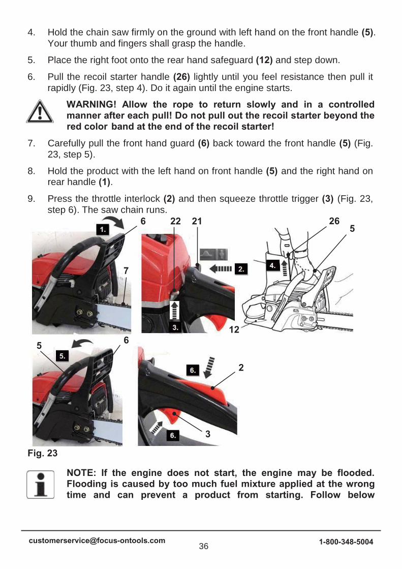
Warm start
1. Push front hand guard (6) forward (Fig. 23, step 1). The saw chain is nowlocked.
2. Ensure the choke (21) is at the OPEN position . Push the choke fully back to the OPEN position if necessary (Fig. 23, step 2).
3. Set the ignition switch (22) to upper position (ON position) (Fig. 23, step 3).
6 2226
12
5
21
21 6
2
3
7
5
1-800-348-500435
4. Hold the chain saw firmly on the ground with left hand on the front handle (5).Your thumb and fingers shall grasp the handle.
5. Place the right foot onto the rear hand safeguard (12) and step down.
6. Pull the recoil starter handle (26) lightly until you feel resistance then pull itrapidly (Fig. 23, step 4). Do it again until the engine starts.
WARNING! Allow the rope to return slowly and in a controlled manner after each pull! Do not pull out the recoil starter beyond the red color band at the end of the recoil starter!
7. Carefully pull the front hand guard (6) back toward the front handle (5) (Fig.23, step 5).
8. Hold the product with the left hand on front handle (5) and the right hand onrear handle (1).
9. Press the throttle interlock (2) and then squeeze throttle trigger (3) (Fig. 23,step 6). The saw chain runs.
Fig. 23
NOTE: If the engine does not start, the engine may be flooded. Flooding is caused by too much fuel mixture applied at the wrong time and can prevent a product from starting. Follow below
6
7
22 215
26
1265
2
3
1-800-348-500436
procedure:
Set the ignition switch (22) to lower position (STOP position).
Push the choke (21) fully back to OPEN position . Remove the spark plug (20) and dry it. Pull the recoil starter handle (26) for several times to drain the fuel from the combustion chamber.
Wait until fuel vapours and refit the spark plug. Clean up any spilled fuel and move the product at least 3 metres (10’) away before starting the engine to avoid any accidental fire. Wait the engine to cool down and then start the product as described in section “Cold start”.
Stopping
1. Release the throttle interlock (2) / throttle trigger (3) and let the product runat its idle speed for 10 – 15 seconds.
2. Set the ignition switch (22) to lower position (STOP position) (Fig. 24).
Fig. 24
WARNING! The cutting device (saw chain) will continue to run for short time even after the engine has been switched off! Wait until the cutting device has come to a complete stop before placing the product on the ground!
NOTE: The product will become very warm after a long time using; allow it to cool down completely before restart. If the productcannot be switched on with warm start procedure, then refer to the cold start procedure.
5. Basic operating / cutting procedure
22
3
1-800-348-500437
1. To become proficient attend a recognised chain saw training course to learnhow to operate chain saws safely and effectively. Familiarise yourself with allthe controls and switches. Practise all movements with the product switchedoff.
2. Always hold the product firmly with both hands. Front handle (6) with the lefthand and rear handle (1) with the right hand. Fully grip both handles at alltimes during operation. Never operate the product using only one hand.
3. Only use the product with a secure stance. Hold the product at the right-hand side of your body (Fig. 25).
Fig. 25
4. Check the proper lubrication as described in section “Operatinginstructions - Chain lubrication” before performing any cut.
5. Ensure the saw chain (7) is running at full speed before it makes contact withthe wood. Use the spiked bumper to secure the product onto the woodbefore starting to cut and use it as a leverage point while cutting (Fig. 26).
Fig. 26
6. Reset the spiked bumper at a low point when cutting thicker logs by pullingthe product slightly backwards until the gripping teeth release, and repositionat lower level to continue sawing. Do not remove the product completelyfrom the wood.
7. Do not force the saw chain while cutting, let the chain do the work, using thegripping teeth to apply minimal leverage pressure.
1-800-348-500438
8. Do not operate the product with arms fully extended or attempt to saw areaswhich are difficult to reach, or on a ladder. Never use the product aboveshoulder height (Fig. 27).
Fig. 27
9. Optimum sawing is achieved if the chain speed remains constant duringcutting.
10. Be careful when reaching the end of the cut. The weight of the product maychange unexpectedly as it cuts free from the wood. This can causeaccidents to the legs and feet. Always remove the product from a wood cutwhile the product is running.
11. Check that the oil feed to the chain is operating correctly; run the chain sawat medium speed and ensure that the chain has received a consistentcoating of oil.
6. Kickback
WARNING! Beware of kickback! Kickback can lead to dangerous loss of control of the product and result in serious or fatal injury to the operator or anyone standing close by! Always be alert because rotational kickback and pinch kickback are major product operational dangers and the leading cause of most accidents!
Kickback may occur if the nose or tip of the guide bar touches an object, or if wood pinches the saw chain in the cut.
In some cases, contact with the tip of the guide bar (8) may cause a lightning-fast reverse reaction, kicking the guide bar up and back toward the operator (Figs. 28- 30).
1-800-348-500439
Fig. 28 Fig. 29 Fig. 30
1. Pinching the saw chain (7) along the bottom of the guide bar (8) may pull theproduct forward away from the operator (“skating”) (Fig. 31).
Fig. 31
2. Pinching the saw chain (7) along the top of the guide bar (8) may push theguide bar rapidly back toward the operator (“bouncing”) (Fig. 32).
Fig. 32
3. Any of these reactions may cause losing control of the product, which couldresult in serious personal injury or even death.
4. With a basic understanding of ‘kickback’, the element of surprise can bereduced or eliminated. Sudden surprise contributes to the majority ofaccidents.
5. Keep a good firm grip on the product with both hands, the right hand on therear handle (1) and the left hand on the front handle (6), when the engine isrunning. Maintain a firm grip with your thumbs and fingers encircling thehandles. A firm grip will help you reduce ‘kickback’ and maintain control ofthe product.
6. You should carefully read all safety warnings and user instructions beforeattempting to operate this product.
1-800-348-500440
To avoid kickback:
Saw with guide bar at a flat angle.
Never work with a loose, widely stretched or the heavily worn out chain.
Ensure chain is sharpened correctly.
Never saw above shoulder height.
Never work with the tip of the guide bar.
Always hold the product firmly with both hands.
Always use a low kickback chain.
Apply the metal gripping teeth for leverage.
Ensure correct chain tension.
Do only cut with the engine at high speeds.
Do not let the nose of the guide bar contact a log, branch, or any otherobstruction which could be hit while you are operating the product.
Follow manufacturer’s sharpening and maintenance instructions for thesaw chain.
Only use replacement guide bars and saw chains specified by themanufacturer or equivalent replacements.
WARNING! Most ‘kickback’ accidents happen during limbing! Payclose attention to the position of the ‘kickback’ zone of the barwhen you are ‘limbing’ branches that are under tension.
7. Felling a tree
1. When bucking and felling operations are being performed by two or morepersons at the same time, the felling operations should be separated fromthe bucking operation by a distance of at least twice the height of the treebeing felled. Trees should not be felled in a manner that would endanger anyperson, strike any utility line or cause any property damage. If the tree doesmake contact with any utility line, the company should be notifiedimmediately.
2. The product operator should keep on the uphill side of the terrain as the treeis likely to roll or slide downhill after it is felled.
1-800-348-500441
3. An escape path should be planned and cleared as necessary before cuts arestarted. The escape path should extend back and diagonally to the rear ofthe expected line of fall (Fig. 33).
Fig. 33
4. Before felling is started, consider the natural lean of the tree, the location oflarger branches and the wind direction to judge which way the tree will fall.
5. Remove dirt, stones, loose bark, nails, staples and wire from the tree.
8. Notching undercut
Make the notch (Fig. 34, B) 1/3 the diameter of the tree, perpendicular to the direction of falls (Fig. 34). Make the lower horizontal notching cut first. This will help to avoid pinching either the saw chain or the guide bar when the second notch is being made.
Fig. 34
9. Felling back cut
1. Make the felling back cut (Fig. 34, A) at least 50 mm higher than thehorizontal notching cut (Fig. 34). Keep the felling back cut parallel to thehorizontal notching cut. Make the felling back cut so enough wood is left toact as a hinge. The hinge (Fig. 34, C) wood keeps the tree from twisting andfalling in the wrong direction. Do not cut through the hinge.
2. As the felling gets close to the hinge, the tree should begin to fall. If there isany chance that the tree may not fall in desired direction or it may rock backand bind the saw chain, stop cutting before the felling back cut is complete
1-800-348-500442
and use wedges of wood, plastic or aluminum to open the cut and drop the tree along the desired line of fall.
3. When the tree begins to fall remove the product from the cut, stop the engine,put the product down, then use the retreat path planned. Be alert foroverhead limbs falling and watch your footing.
10. Limbing and pruning
Limbing is removing the branches from a fallen tree. When limbing leave larger lower limbs to support the log off the ground. Remove the small limbs in one cut (Fig. 35). Branches under tension should be cut from the bottom up to avoid binding the product.
Fig. 35
WARNING! Never climb into a tree to limb or prune! Do not stand on ladders, platforms, logs, or in any position which may cause you to lose the balance or control of the saw! When pruning trees, it is important not to make the flush cut next to main limp or trunk until you have cut off the limb further out to reduce the weight! This prevents stripping the bark from the main member!
WARNING! If the limbs to be pruned are above chest height, hire a professional to perform the pruning!
11. Cutting spring poles
A spring pole is any log, branch, rooted stump, or sapling which is bent under tension by other wood so that it springs back if the wood holding it is cut or removed (Fig. 36).
On a fallen tree, a rooted stump has a high potential of springing back to the upright position during the bucking cut to separate the log from the stump.
Watch out for spring poles, they are dangerous.
1-800-348-500443
Fig. 36
12. Bucking a log
Bucking is cutting a log into lengths. It is important to make sure your footing is firm and your weight is evenly distributed on both feet. When possible, the log should be raised and supported by the use of limbs, logs or chocks.
1. Follow the simple directions for easy cutting. When the log is supportedalong its entire length (Fig. 37), it is cut from the top (overbuck).
Fig. 37
2. When the log is supported on one end (Fig. 38), cut 1/3 the diameter fromthe underside (underbuck). Then make the finished cut by overbucking tomeet the first cut.
Fig. 38
3. When the log is supported on both ends (Fig. 39), cut 1/3 the diameter fromthe top (overbuck). Then make the finished cut by underbucking the lower2/3 to meet the first cut.
Fig. 39
1-800-348-500444
4. When bucking on a slope always stand on the uphill side of the log (Fig. 40).When “cutting through”, to maintain complete control release the cuttingpressure near the end of the cut without relaxing your grip on the producthandles. Do not let the chain contact the ground. After completing the cut,wait for the saw chain to stop before you move the product. Always stop theengine before moving from tree to tree.
Fig. 40
5. Support small logs on a sawing stand or another log while bucking (Fig. 41).
Fig. 41
6. If the wood diameter is large enough for you to insert a soft bucking wedgewithout touching the chain, you should use the wedge to hold the cut open toprevent pinching (Fig. 42).
Fig. 42
13. After use
1-800-348-500445
1. Switch the product off, disconnect the spark plug connector and let it cooldown.
2. Check, clean and store the product as described below.
MAINTENANCE AND CARE
WARNING! Always switch the product off, disconnect the spark plug connector and let the product cool down before performing inspection, maintenance and cleaning work!
Maintain this product regularly and carefully! If the product is improperly maintained, it may fail at its intended task, which may produce fatal consequences.
1. Keep the product clean. Remove debris from it after each use and beforestorage.
2. Regular and proper cleaning will help ensure safe use and prolong the life ofthe product.
3. Inspect the product before each use for worn and damaged parts. Do notoperate it if you find broken and worn parts.
WARNING! Only perform repairs and maintenance work according to these instructions! All further works must be performed by a qualified specialist!
1. General cleaning
1. Clean the product with a dry cloth and mild soap. Use a brush for areas thatare hard to reach.
2. In particular clean the air vents (28) after every use with a cloth and brush.
3. Remove stubborn dirt with high pressure air (max. 3 bar).
NOTE: Do not use chemical, alkaline, abrasive or other aggressive detergents or disinfectants to clean this product as they might be harmful to its surfaces.
4. Check for any damage and wear. Repair damages in accordance with thisinstruction manual or take it to an authorised service centre or a similarlyqualified person before using the product again.
2. Maintenance table
Inspect and maintain this product regularly based on below maintenance table.
1-800-348-500446
Part To do Before/after each use
10hours
25hours
50hours / half year
100hours / once a year
Spark plug
check x
Spark plug
clean x
Spark plug
replace whenever necessary
Air filter check x
Air filter clean x
Air filter replace whenever necessary
Saw chain
check x
Saw chain
lubricate x
Saw chain
clean x
Saw chain
replace whenever necessary
3. Sprocket wheel
NOTE: It is not necessary to remove the saw chain (7) to lubricate the sprocket. Lubrication can be done on the job.
1. Clean the sprocket wheel (8b).
2. Using a disposable lube gun, insert the needle nose into the lubrication hole(8a) and inject grease until it appears at the outside edge of the sprocket (Fig.43).
1-800-348-500447
Fig. 43
3. Make sure that the chain brake is disengaged. Rotate the saw chain (7) byhand. Repeat the lubrication procedure until the entire sprocket has beengreased.
4. Guide bar and saw chain maintenance
Most guide bar problems can be prevented merely by keeping the product well maintained. Incorrect filing and non-standard cutter and depth gauge settings are the causes of most guide bar problems, primarily resulting in uneven bar wear. As the bar wears unevenly, the rails widen, which may cause the chain to clatter and make it difficult to complete straight cuts. If the guide bar is insufficiently lubricated and the product is operated with a saw chain which is too tight, this will contribute to rapid bar wear. To help minimise bar wear, maintenance of the guide bar as well as the saw chain is recommended.
1. Disassemble the guide bar and saw chain in reversed order from assembly.
2. Check the oiling port (14) for clogging and clean if necessary to ensure properlubrication of the guide bar and saw chain during operation. Use a soft wiresmall enough to insert into the oil discharge hole (Fig. 44).
Fig. 44
NOTE: The condition of the oil passages can be easily checked. If the passages are clear, the chain will automatically give off a spray of oil within seconds of the product starting. Your product is
7 8a
14
8b
1-800-348-500448
equipped with an automatic oiling system.
3. Check the drive sprocket. If it is worn or damaged due to strain, have itreplaced by an authorised service centre or a similarly qualified person.
4. Clear residue from the rails on the guide bar (8) using a screwdriver, puttyknife, wire brush or other similar tool. This will keep the oil passages open toprovide proper lubrication to the guide bar (8) and saw chain (7) (Fig. 45).
Fig. 45
5. Check the guide bar ‘rail’ for wear: Hold a ruler (straight edge) against theside of the guide bar and ‘cutter side plates’. If there is a gap between theruler and guide bar the guide bar ‘rail’ is normal. If there is no gap (ruler flushagainst the side of the guide bar) the guide bar ‘rail’ is worn and needs to bereplaced with a new one of the same type (Fig. 46).
Fig. 46
6. Turn the guide bar 180° to allow even wear, thereby extending the life span ofthe guide bar (8).
7. Check the saw chain for possible wear and damages. Replace it with a newone if required. Experienced user can sharpen a dull saw chain (see section“Saw chain sharpening” below).
8. Refit the saw chain (7) and the guide bar (8) as described under section“Assembly”.
5. Saw chain sharpening
NOTE: Saw chain sharpening may be required:
- after damp wood is cut (mealy sawdust),
- when handling the product becomes difficult (pulls to the left
1-800-348-500449
or right),
- when the saw chain is blunt (excessive force is required topenetrate the wood), or obviously damaged.
Never saw with a blunt chain. The saw chain is blunt if you have to push the product into the tree and the chips are very small.
1. Have the saw chain (7) sharpened professionally at an authorised servicecentre or sharpen the chain yourself by using a proper sharpening kit. Alsoobserve the sharpening instructions supplied with the sharpening kit.
WARNING! Only sharpen the saw chain yourself if you are trained and have experience! Use proper tools to sharpen the saw chain!
2. The height difference between the tooth and the ridge is the cutting depth.When sharpening the saw chain (7) you have to consider the following points(Fig. 47).
- File angle
- Cutting angle
- File position
- Diameter of round file
- File depth
Fig. 47
3. To sharpen the chain proceed as follows:
- Use protective gloves.
- Ensure the chain is correctly tensioned.
- Engage the chain brake to lock the chain on the bar.
4. Use the chain file (not delivered), whose diameter is 1.1 times the cuttingtooth depth. Make sure 20% of the file diameter is above the cutter’s top plate.
1-800-348-500450
NOTE: A file guide is available from most reputable tool merchants and is the easiest way to hold the file at the correct position.
5. File at an angle perpendicular to the bar, and at an angle of 30° to thedirection of travel (Fig. 48).
Fig. 48
6. File each tooth from the inside towards outside only. File one side of the chainfirst than turn the saw around and repeat the process.
7. Sharpen each tooth equally by using the same number of strokes.
8. Keep all cutter lengths equal. Check the safety depth gauge height every 5sharpenings. If the depth gauges are also trimmed it is essential that theoriginal profile be restored.
9. Use a depth gauge measuring instrument to check the height of the depthgauge. Depth gauge measuring jigs are available from most reputable toolmerchants (Fig. 49).
Fig. 49
6. Air filter
30
1-800-348-500451
Wash the air filter every 25 hours (if too dusty, every 10 hours) with clear water and dry it. Dip the air filter into clean machine oil if necessary. It can be used after superfluous oil is eliminated.
Inspect the air filter regularly. Replace it with a new one if necessary (Fig. 50).
Fig. 50
1. Loosen the fixation knob (4a) and remove the cover (4b) to open the air filtercase (4).
2. Remove the filter (4c) and tap it on a solid surface to remove dust.
3. Apply a small amount of air filter oil on the filter (4c) to increase theperformance of the filter. Wring out surplus oil and put the filter back to the airfilter case.
4. Re-attach the cover (4b) and secure it with the fixation knob (4a).
7. Spark plug
Inspect the spark plug every 25 hours or prior to long-term storage over 30 days if the use has not been this high. Clean or replace with a new one if necessary.
1. Open the air filter case (4) and remove the air filter (4c) as described.
2. Disconnect the spark plug connector (19) (Fig. 51).
3. Loosen the spark plug (20) anticlockwise using the multi tool (32) and removeit carefully (Fig. 52).
4a4b
4c
1-800-348-500452
Fig. 51 Fig. 52
4. Check the spark plug (20) for damage and wear. The color of the electrodeshould be light-brown colored.
5. Remove debris from the electrode with a soft wired brush; avoid heavycleaning of the electrode.
6. Dry the spark plug with a soft cloth, if it is wet from fuel.
7. Check the spark plug gap. It should be 0.6 - 0.7mm(Fig. 53).
Fig. 53
8. Replace with a new spark plug if either the electrode or the insulation isdamaged.
9. When replacing the spark plug, first screw it in hand tight and then lightlytighten it with the multi tool (32).
10. Refit the spark plug connector (19); ensure the rubber pad around the sparkplug connector is in correct position.
WARNING! Do not over tighten the spark plug to avoid any damage!
0.6 - 0.7mm
192032
1-800-348-500453
11. Place the filter (4c) back into the air filter case (4), re-attach the cover (4b)and secure it with the fixation knob (4a) afterward.
8. Fuel tank
1. Empty the fuel tank when storing the product over 30 days to prevent the fueldeteriorating.
2. Unscrew and remove the fuel tank cap (24) and empty the fuel into a suitablecontainer.
WARNING! Do not store the fuel in the fuel mixing container (31)!
9. Fuel filter
The fuel tank of this product is fitted with a filter, which is attached on the end of the fuel pipe. Ask an authorised service centre or a similarly qualified person to check and replace the filter at regular intervals if required.
10. Carburetor
The carburetor is pre-set by the manufacturer. Should it be necessary to make any changes please contact an authorised service centre or a similarly qualified person. Do not attempt to make any adjustments by yourself.
11. Muffler
If it be necessary to modify or replace the muffler, please contact an authorised service centre or a similarly qualified person.
12. Spare parts/Replacement parts
The following parts of this product may be replaced by the consumer. Spare parts are available at an authorised dealer or through our customer service.
Description Model No. or Specification
Guide bar 200PXBW095 / 208PXBK095 / Blue Max 5651 / 21115
Saw chain 20LPX078X / 21PX078X / Blue Max 52208 / 21117
WARNING! Saw chain must be fitted with guide bar according to above combination. Use only the same brand and same type of saw chain and guide bar as above. The use of non-approved guide bar /saw chain combinations poses a severe risk of injury!
13. Repair
This product does not contain any parts that can be repaired by the consumer. Contact an authorised service centre or a similarly qualified person to have it checked and repaired.
14. Storage
1. Switch the product off and disconnect the spark plug connector.
2. Clean the product as described above.
3. Attach the guide bar cover.
4. Store the product and its accessories in a dark, dry, frost-free, well-ventilatedplace.
5. Always store the product in a place that is inaccessible to children. The idealstorage temperature is between 10°C and 30°C.
6. We recommend using the original package for storage or covering theproduct with a suitable cloth or enclosure to protect it against dust.
7. Empty the tank if you are not going to use the product for an extended periodof time (more than 30 days) and before storing it for the winter.
15. Transportation
1. Switch the product off and disconnect the spark plug connector.2. Attach the guide bar cover.
3. Always carry the product by its handles (1, 5).
4. Protect the product from any heavy impact or strong vibrations which mayoccur during transportation in vehicles.
5. Secure the product to prevent it from slipping or falling over, loss of fuel,damage and injury.
16. Recycling and disposal
1. Old products are potentially recyclable and do not, therefore, belong in yourhousehold rubbish. You are requested to assist us and our contribution to
1-800-348-500455
saving resources and protecting the environment by handing in this product at an equipped collection centre (if there is one available).
2. Petrol, oil, used oil, a mixture of oil and petrol and objects soiled with oil e.g.cleaning cloths do not belong in the household rubbish. Dispose of oil-contaminated items in accordance with the local guidelines and hand them inat recycling centres.
3. The product comes in a package that protects it against damage duringshipping. Keep the package until you are sure that all parts have beendelivered and the product is function properly. Recycle the packageafterwards.
TROUBLE SHOOTING
Suspected malfunctions are often due to causes that the user can fix themselves. Therefore check the product using this section. In most cases the problem can be solved quickly.
WARNING! Only perform the steps described within these instructions! All further inspection, maintenance and repair work must be performed by an authorised service centre or a similarly qualified specialist if you cannot solve the problem yourself!
Problem Possible cause Solution
1. Engine does notstart
1.1. Not enough fuel in fuel tank
1.1. Add fuel
1.2. Spark plug is wet 1.2. Dry spark plug
1.3. Spark plug is damaged
1.3. Replace spark plug
1.4. Spark plug connector lose
1.4. Attach properly
1.5. Ignition switch is not set to upper position
1.5. Set ignition switchto upper position
1.6. Air filter is dirty 1.6. Clean air filter
1.7. Spark plug loose 1.7. Tighten spark plug
1.8. Spark plug gap is incorrect
1.8. Set gap between e0.6 - 0.7mmlectrodes at
1-800-348-500456
1.9. Carburetor is flooded with fuel
1.9. Remove air filter and pull recoil starter handle continuously until carburetor clears itself and install air filter
1.10. Faulty ignition module
1.10. Contact anauthorised service centre or a similarly qualified person
2. Engine stops 2.1. Not enough fuel in fuel tank
2.1. Add fuel
2.2. Saw chain is blocked 2.2. Remove blockage
3. Engine difficult tostart or loses power
3.1. Dirt, water or stale fuel in the tank
3.1. Drain fuel and clean tank. Fill tank with clean, fresh fuel
3.2. Air filter is dirty 3.2. Clean air filter
3.3. Fuel filter/fuel tube clogged/worn
Contact authorised service centre or a similarly qualified person
3.4. Vent hole in fuel tank cap is clogged
3.4. Clean or replace fuel tank cap
4. Engine operateserratically
4.1. Spark plug is defective
4.1. Install new, correctly gapped plug
4.2. Spark plug gap is incorrect
4.2. Set gap between electrodes at 0.6 - 0.7mm
4.3. Air filter is dirty 4.3. Clean air filter
4.4. Engine requires to warm up
4.4. Allow engine to completely warm up and run at idle speed for 3minminutes
1-800-348-500457
5. Engine idles poorly 5.1. Air filter is dirty 5.1. Clean air filter
5.2. Air vents are clogged
5.2. Remove debris from vents
6. Engine skips at highspeed
6.1. Gap between electrodes of spark plug is too close
6.1. Set gap between electrodes at 0.6 - 0.7mm
7. Engine overheats 7.1. Air vents are clogged
7.1. Remove debris from vents
7.2. Incorrect spark plug 7.2. Install correct spark plug and cylinder fins on engine
7.3. Saw chain is blocked
7.3. Remove blockage
8. Unsatisfactory result 8.1. Saw chain is worn 8.1. Have a specialist to sharpen or replace it
8.2. Saw chain not tensioned properly
8.2. Tension properly
8.3. Blunt saw chain 8.3. Only cut branches within the limits
8.4. Improper chain speed
Have a specialist to adjust it
9. Excessivevibration/noise orexhaust
9.1. Saw chain is dull/damaged
9.1. Have it replaced with a new one
9.2. Bolts/nuts are loosen 9.2. Tighten bolts/nuts
9.3. Fuel is incorrect 9.3. Empty out unused fuel and refill with the correct fuel
1-800-348-500458
1-800-348-500459
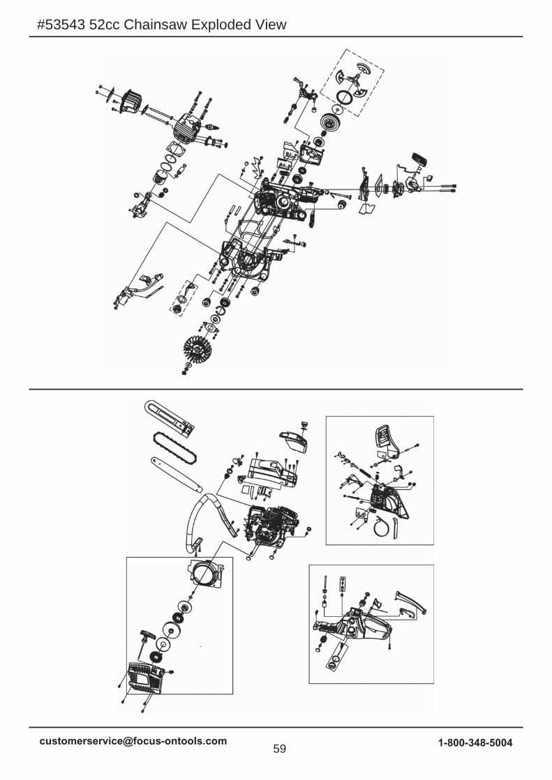
#53543 52cc Chainsaw Exploded View
1-800-348-500460
A. Handle, Fuel Tank
Part No.
A1A2A3
A3-1A3-2A3-3A4A5A6A7A8A9
A10A11A12A13A14A15A16A17A18A19A20
11111122211111111111141
Fuel TankScrew St4.2x19Gasoline Tank Cap AssemblyFuel Cap RetainerPacking WasherFuel Tank CapDust CoverScrew M5x16Anti-Vibration Cushion CDamping BlockFuel Filter Increase BlockFuel Tube BaseFuel TubeBlock BalancerBalancer AssemblyTriggerTrigger Torsion Rod SpringPin 6x24Trigger ControllerHandle CoverScrew St4.8x16Front Handle
Dust BoardRight CoverNut M8Heavy Block Torsion SpringHeavy Block TubeHeavy BlockFront Guard SpringSpring IntakeScrew M5x37.5Front Guard TubeFront Guard Brake Torsion Rod SpringFlat Washer 5x18x1Nut M5Brake SpringBrake Control RodSecondary Pull-rodMain Pull-rodPin 3x14Pin 3x9Brake Spring Pressure PlateScrew St4.2x9.5TightenerScrew M5x50Tightening GearTightener CoverBrake BeltAluminized Paper
Parts Description Quantity
1-800-348-500462
C. Starter Assembly
Part No.
C1C2
C2-1C2-2C2-3C2-4C2-5C2-6C2-7C2-8C2-9
C2-10C2-11C2-12
C3
411111111111111
Screw M5x16Starter AssemblySuper Easy Starter CoverL H SheathingRope SheathingStarting RopeStarting HandleMain Coil Spring Main Coil Spring ShellReel Second Coil Spring Starter WheelFlat Washer 5.4x16x1Screw St4.8x13Cooling-Air Mask
FOT makes every effort to ensure that this product meets high quality and durabilitystandards. FOT warrants to the original retail consumer a 1-year limited warrantyfrom the date the product was purchased at retail and each product is free fromdefects in materials. Warranty does not apply to defects due directly or indirectlyto misuse, abuse, negligence or accidents, repairs or alterations, or a lack ofmaintenance. FOT shall in no event be liable for death, injuries to persons orproperty, or for incidental, special or consequential damages arising from theuse of our products. To receive service under warranty, the original manufacturerpart must be returned for examination by an authorized service center. Shippingand handling charges may apply. If a defect is found, FOT will either repair orreplace the product at its discretion.
DO NOT RETURN TO STOREFor Customer Service:Email: [email protected] oCall 1-800-348-5004