Page 1
AIS-024 (Version 5): 2016
I
AIS-024
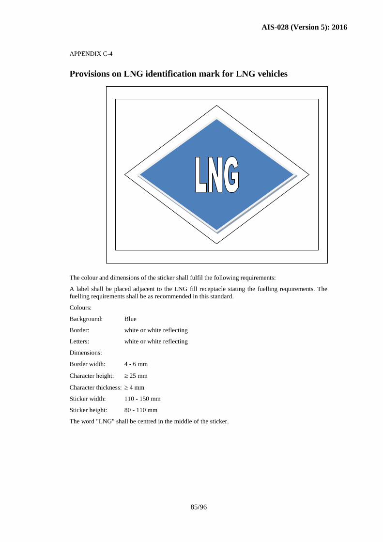
SAFETY AND PROCEDURAL REQUIREMENTS
FOR TYPE APPROVAL OF
CNG/Bio-CNG/LNG OPERATED VEHICLES
(DEDICATED, BI-FUEL & DUAL FUEL)
(Version 5)
AND
AIS-028
CODE OF PRACTICE FOR USE OF CNG/Bio-
CNG/LNG FUEL IN INTERNAL COMBUSTION
ENGINED VEHICLES
(Version 5)
PRINTED BY
THE AUTOMOTIVE RESEARCH ASSOCIATION OF INDIA
P.B. NO. 832, PUNE 411 004
ON BEHALF OF
AUTOMOTIVE INDUSTRY STANDARDS COMMITTEE
UNDER
CENTRAL MOTOR VEHICLE RULES – TECHNICAL STANDING COMMITTEE
SET-UP BY
MINISTRY OF ROAD TRANSPORT & HIGHWAYS
(DEPARTMENT OF ROAD TRANSPORT & HIGHWAYS)
GOVERNMENT OF INDIA
2016
Page 2
AIS-024 (Version 5): 2016
II
AMENDMENT RECORD
This document contains AIS-024 and AIS-028
Version 1 Effective from 21st May 2001 Discontinued from 12
th July
2001
Version 2 Effective from 12th
July 2001
Version 3 Effective from 26th
February 2002
Version 4 Effective from Aug 2015
Version 5 Effective from September 2016
Page 3
AIS-024 (Version 5): 2016
III
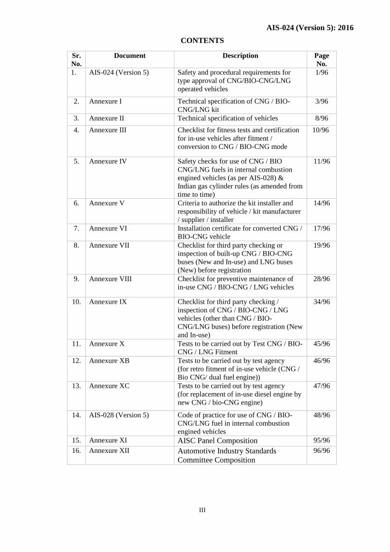
CONTENTS
Sr.
No.
Document Description Page
No.
1. AIS-024 (Version 5) Safety and procedural requirements for
type approval of CNG/BIO-CNG/LNG
operated vehicles
1/96
2. Annexure I Technical specification of CNG / BIO-
CNG/LNG kit
3/96
3. Annexure II Technical specification of vehicles 8/96
4. Annexure III Checklist for fitness tests and certification
for in-use vehicles after fitment /
conversion to CNG / BIO-CNG mode
10/96
5. Annexure IV Safety checks for use of CNG / BIO
CNG/LNG fuels in internal combustion
engined vehicles (as per AIS-028) &
Indian gas cylinder rules (as amended from
time to time)
11/96
6. Annexure V Criteria to authorize the kit installer and
responsibility of vehicle / kit manufacturer
/ supplier / installer
14/96
7. Annexure VI Installation certificate for converted CNG /
BIO-CNG vehicle
17/96
8. Annexure VII Checklist for third party checking or
inspection of built-up CNG / BIO-CNG
buses (New and In-use) and LNG buses
(New) before registration
19/96
9. Annexure VIII Checklist for preventive maintenance of
in-use CNG / BIO-CNG / LNG vehicles
28/96
10. Annexure IX Checklist for third party checking /
inspection of CNG / BIO-CNG / LNG
vehicles (other than CNG / BIO-
CNG/LNG buses) before registration (New
and In-use)
34/96
11. Annexure X Tests to be carried out by Test CNG / BIO-
CNG / LNG Fitment
45/96
12. Annexure XB Tests to be carried out by test agency
(for retro fitment of in-use vehicle (CNG /
Bio CNG/ dual fuel engine))
46/96
13. Annexure XC Tests to be carried out by test agency
(for replacement of in-use diesel engine by
new CNG / bio-CNG engine)
47/96
14. AIS-028 (Version 5) Code of practice for use of CNG / BIO-
CNG/LNG fuel in internal combustion
engined vehicles
48/96
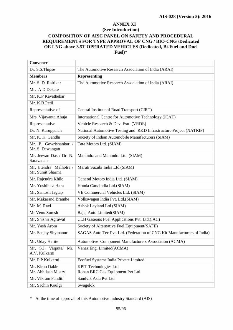
15. Annexure XI AISC Panel Composition 95/96
16. Annexure XII Automotive Industry Standards
Committee Composition
96/96
Page 4
AIS-024 (Version 5): 2016
IV
INTRODUCTION
The Government of India felt the need for a permanent agency to expedite the
publication of standards and development of test facilities in parallel when the
work on the preparation of the standards is going on, as the development of
improved safety critical parts can be undertaken only after the publication of the
standard and commissioning of test facilities. To this end, the erstwhile Ministry of
Surface Transport (MOST) has constituted a permanent Automotive Industry
Standards Committee (AISC) vide order No. RT-11028/11/97-MVL dated
September 15, 1997. The standards prepared by AISC will be approved by the
permanent CMVR Technical Standing Committee (CMVR-TSC). After approval,
the Automotive Research Association of India, (ARAI), Pune, being the Secretariat
of the AIS Committee, will publish this standard. For better dissemination of this
information ARAI may publish this document on their Web site.
Version 5 of AIS-024 and AIS-028 is prepared to include safety and procedural
requirements for type approval of CNG / BIO-CNG/ LNG (dedicated HCV
vehicles only) operated vehicles using Dual Fuel technology in addition to
Dedicated and Bi-Fuel technology. It may be noted that Liquefied Natural Gas
(LNG) shall be permitted for dedicated OE manufactured Vehicles having GVW ≥
3.5 T .
The AISC panel responsible for formulation of this standard is given in Annex XI.
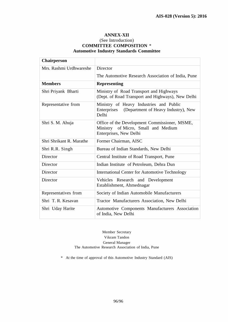
The Automotive Industry Standards Committee (AISC) responsible for approval of
this standard is given in Annex XII.
Page 5
AIS-024 (Version 5): 2016
1/89
SAFETY AND PROCEDURAL REQUIREMENTS FOR TYPE APPROVAL OF CNG
/ BIO-CNG / LNG OPERATED VEHICLES (DEDICATED, BI-FUEL & DUAL FUEL
as applicable)
For CNG / BIO-
CNG/LNG** Fitment
by OE Manufacturer
for New Vehicle
For Retrofitment of
In-Use Vehicle (CNG /
BIO CNG/ Dual Fuel
Engine)
For Replacement of
In-Use Diesel Engine by
New CNG / BIO-
CNGEngine
Documents to be
submitted
Specification of CNG /
BIO-CNG/LNG kit in
the given format as per
Annexure I.
Detailed and brief
technical specifications
of vehicle in AISC
format (AIS-007).
Specification of CNG /
BIO-CNGkit as per
Annexure I.
Technical specification of
the retrofitted vehicle as
per Annexure II.
Details of alterations
carried out on diesel
engine to CNG / BIO-
CNG along with names of
the supplier.
Specification of CNG /
BIO-CNGkit as per
Annexure I.
Technical specifications of
in-use diesel vehicle as per
Annexure II.
Technical specification of
vehicle and CNG / BIO-
CNGengine as per Table 2
and 4 of AIS-007.
CMVR Checks CMVR checks / tests
are to be conducted by
Test Agency as per
CMVR No. 93 to 125.
Certificates of original
petrol/diesel engined
vehicles to be produced
for checking
compliance of as many
common rules of
CMVR for petrol/
diesel vehicle and CNG
/ BIO-CNG/LNG
vehicle.
Whichever rules are not
complied with because
of changes made for
conversion, the same
are to be re-checked as
per applicable CMVR.
Undertaking by the kit
manufacturer/ supplier
regarding fitness (as per
Annexure III) and fitness
compliance as per CMVR
as amended by the
Government of India from
time to time, of the in-use
vehicle to be submitted to
the test agency for the
examination and
evaluation before
undertaking performance
tests on CNG / BIO-
CNGfuelled vehicles.
Assessment of structural
integrity in case of heavy
passenger/goods diesel
vehicles to be provided by
the retrofitter or kit
installer.
Undertaking by the vehicle
manufacturer/kit
manufacturer/ kit supplier
regarding fitness (as per
Annexure III) and fitness
compliance as per CMVR
as amended by the
Government of India from
time to time, of the in-use
vehicle to be submitted to
the test agency for the
examination and evaluation
before undertaking
performance test on CNG /
BIO-CNGfuelled vehicles.
Assessment of structural
integrity in case of heavy
passenger/goods diesel
vehicles to be provided by
the retrofitter or kit
installer.
Performance
Tests as per
CMVR
As per Annexure X-a
of AIS-024*.
As per Annexure X-b of
AIS-024*.
As per Annexure X-c of
AIS-024*.
Page 6
AIS-024 (Version 5): 2016
2/89
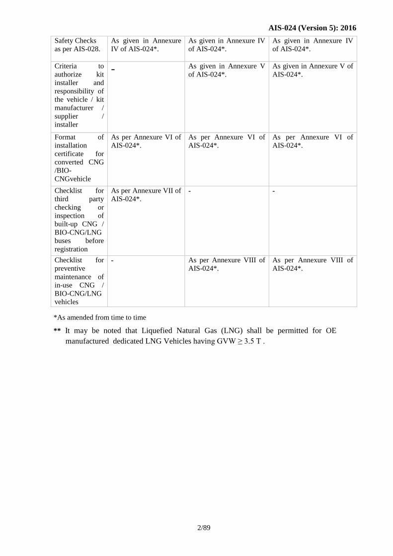
Safety Checks
as per AIS-028.
As given in Annexure
IV of AIS-024*.
As given in Annexure IV
of AIS-024*.
As given in Annexure IV
of AIS-024*.
Criteria to
authorize kit
installer and
responsibility of
the vehicle / kit
manufacturer /
supplier /
installer
- As given in Annexure V
of AIS-024*.
As given in Annexure V of
AIS-024*.
Format of
installation
certificate for
converted CNG
/BIO-
CNGvehicle
As per Annexure VI of
AIS-024*.
As per Annexure VI of
AIS-024*.
As per Annexure VI of
AIS-024*.
Checklist for
third party
checking or
inspection of
built-up CNG /
BIO-CNG/LNG
buses before
registration
As per Annexure VII of
AIS-024*. - -
Checklist for
preventive
maintenance of
in-use CNG /
BIO-CNG/LNG
vehicles
- As per Annexure VIII of
AIS-024*.
As per Annexure VIII of
AIS-024*.
*As amended from time to time
** It may be noted that Liquefied Natural Gas (LNG) shall be permitted for OE
manufactured dedicated LNG Vehicles having GVW ≥ 3.5 T .
Page 7
AIS-024 (Version 5): 2016
Vehicle Model Engine No.
Year of manufacture Chassis No.
Vehicle Registration/Identification No:
Name of the Kit Installer Document No. (indicating also revision
status) Signature with Seal
Name
Designation
Date Sheet No.--------of--------
3/89
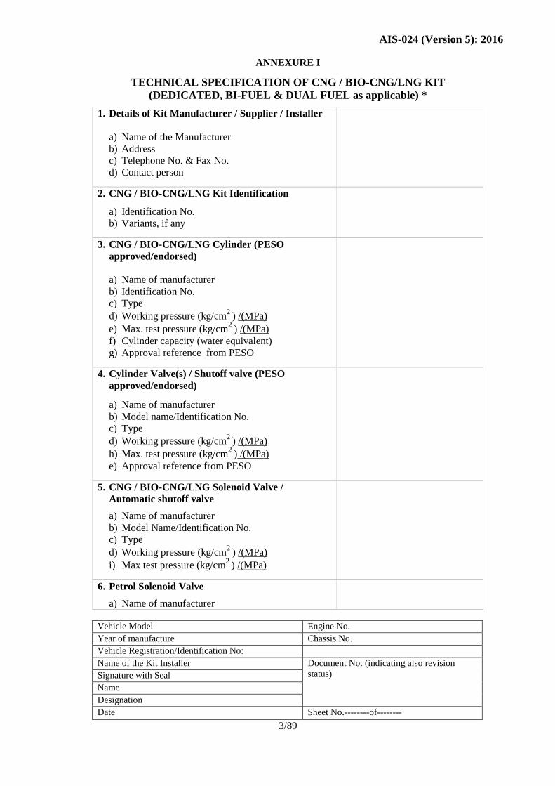
ANNEXURE I
TECHNICAL SPECIFICATION OF CNG / BIO-CNG/LNG KIT
(DEDICATED, BI-FUEL & DUAL FUEL as applicable) *
1. Details of Kit Manufacturer / Supplier / Installer
a) Name of the Manufacturer
b) Address
c) Telephone No. & Fax No.
d) Contact person
2. CNG / BIO-CNG/LNG Kit Identification
a) Identification No.
b) Variants, if any
3. CNG / BIO-CNG/LNG Cylinder (PESO
approved/endorsed)
a) Name of manufacturer
b) Identification No.
c) Type
d) Working pressure (kg/cm2
) /(MPa)
e) Max. test pressure (kg/cm2
) /(MPa)
f) Cylinder capacity (water equivalent)
g) Approval reference from PESO
4. Cylinder Valve(s) / Shutoff valve (PESO
approved/endorsed)
a) Name of manufacturer
b) Model name/Identification No.
c) Type
d) Working pressure (kg/cm2
) /(MPa)
h) Max. test pressure (kg/cm2
) /(MPa)
e) Approval reference from PESO
5. CNG / BIO-CNG/LNG Solenoid Valve /
Automatic shutoff valve
a) Name of manufacturer
b) Model Name/Identification No.
c) Type
d) Working pressure (kg/cm2
) /(MPa)
i) Max test pressure (kg/cm2
) /(MPa)
6. Petrol Solenoid Valve
a) Name of manufacturer
Page 8
AIS-024 (Version 5): 2016
4/89
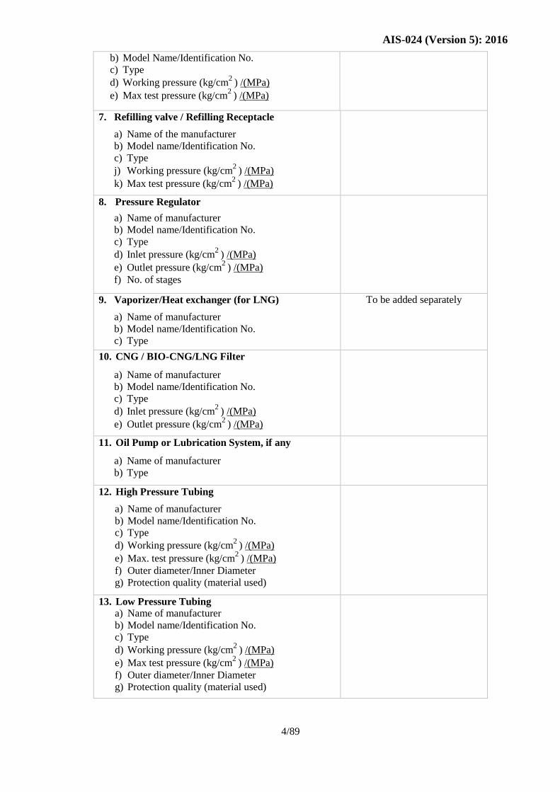
b) Model Name/Identification No.
c) Type
d) Working pressure (kg/cm2
) /(MPa)
e) Max test pressure (kg/cm2
) /(MPa)
7. Refilling valve / Refilling Receptacle
a) Name of the manufacturer
b) Model name/Identification No.
c) Type
j) Working pressure (kg/cm2
) /(MPa)
k) Max test pressure (kg/cm2
) /(MPa)
8. Pressure Regulator
a) Name of manufacturer
b) Model name/Identification No.
c) Type
d) Inlet pressure (kg/cm2
) /(MPa)
e) Outlet pressure (kg/cm2
) /(MPa)
f) No. of stages
9. Vaporizer/Heat exchanger (for LNG)
a) Name of manufacturer
b) Model name/Identification No.
c) Type
To be added separately
10. CNG / BIO-CNG/LNG Filter
a) Name of manufacturer
b) Model name/Identification No.
c) Type
d) Inlet pressure (kg/cm2
) /(MPa)
e) Outlet pressure (kg/cm2
) /(MPa)
11. Oil Pump or Lubrication System, if any
a) Name of manufacturer
b) Type
12. High Pressure Tubing
a) Name of manufacturer
b) Model name/Identification No.
c) Type
d) Working pressure (kg/cm2
) /(MPa)
e) Max. test pressure (kg/cm2
) /(MPa)
f) Outer diameter/Inner Diameter
g) Protection quality (material used)
13. Low Pressure Tubing
a) Name of manufacturer
b) Model name/Identification No.
c) Type
d) Working pressure (kg/cm2
) /(MPa)
e) Max test pressure (kg/cm2
) /(MPa)
f) Outer diameter/Inner Diameter
g) Protection quality (material used)
Page 9
AIS-024 (Version 5): 2016
5/89
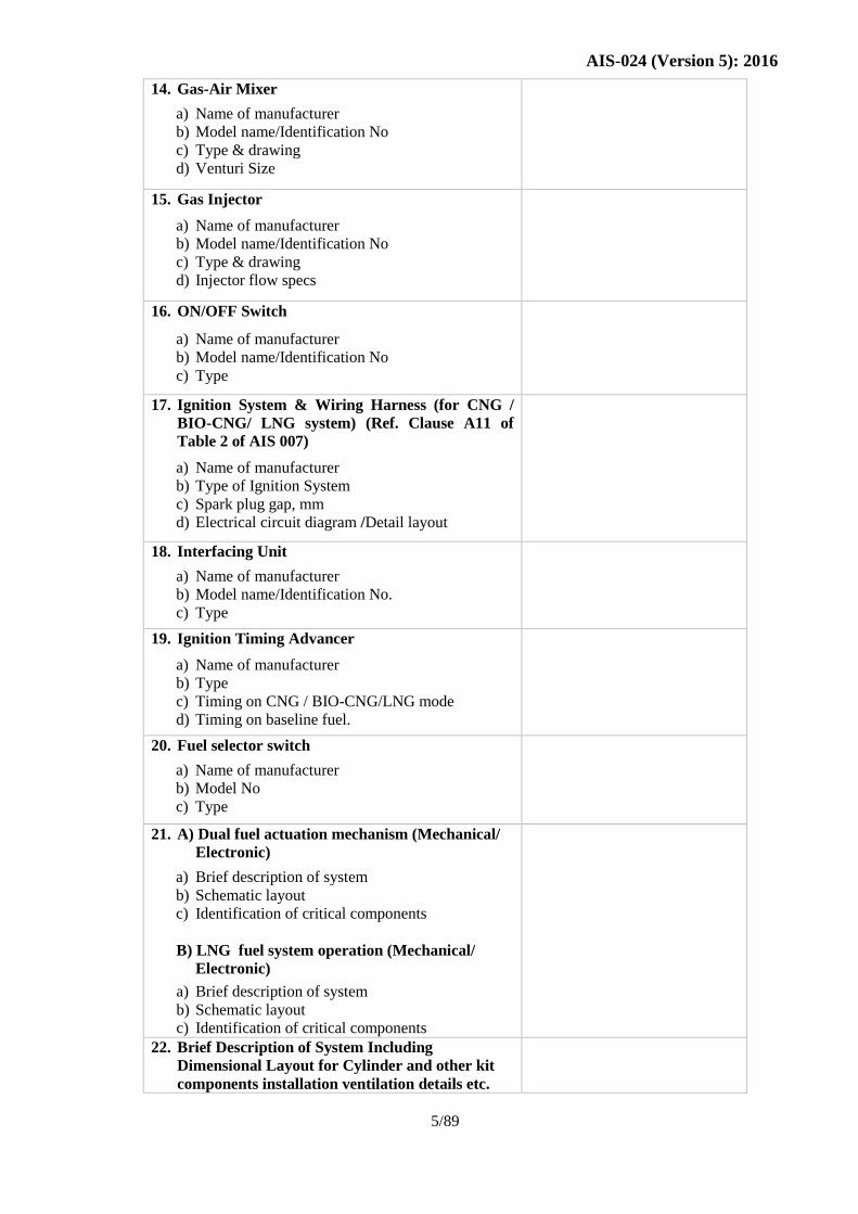
14. Gas-Air Mixer
a) Name of manufacturer
b) Model name/Identification No
c) Type & drawing
d) Venturi Size
15. Gas Injector
a) Name of manufacturer
b) Model name/Identification No
c) Type & drawing
d) Injector flow specs
16. ON/OFF Switch
a) Name of manufacturer
b) Model name/Identification No
c) Type
17. Ignition System & Wiring Harness (for CNG /
BIO-CNG/ LNG system) (Ref. Clause A11 of
Table 2 of AIS 007)
a) Name of manufacturer
b) Type of Ignition System
c) Spark plug gap, mm
d) Electrical circuit diagram /Detail layout
18. Interfacing Unit
a) Name of manufacturer
b) Model name/Identification No.
c) Type
19. Ignition Timing Advancer
a) Name of manufacturer
b) Type
c) Timing on CNG / BIO-CNG/LNG mode
d) Timing on baseline fuel.
20. Fuel selector switch
a) Name of manufacturer
b) Model No
c) Type
21. A) Dual fuel actuation mechanism (Mechanical/
Electronic)
a) Brief description of system
b) Schematic layout
c) Identification of critical components
B) LNG fuel system operation (Mechanical/
Electronic)
a) Brief description of system
b) Schematic layout
c) Identification of critical components
22. Brief Description of System Including
Dimensional Layout for Cylinder and other kit
components installation ventilation details etc.
Page 10
AIS-024 (Version 5): 2016
6/89
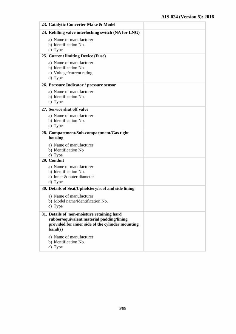
23. Catalytic Converter Make & Model
24. Refilling valve interlocking switch (NA for LNG)
a) Name of manufacturer
b) Identification No.
c) Type
25. Current limiting Device (Fuse)
a) Name of manufacturer
b) Identification No.
c) Voltage/current rating
d) Type
26. Pressure Indicator / pressure sensor
a) Name of manufacturer
b) Identification No.
c) Type
27. Service shut off valve
a) Name of manufacturer
b) Identification No.
c) Type
28. Compartment/Sub-compartment/Gas tight
housing
a) Name of manufacturer
b) Identification No
c) Type
29. Conduit
a) Name of manufacturer
b) Identification No.
c) Inner & outer diameter
d) Type
30. Details of Seat/Upholstery/roof and side lining
a) Name of manufacturer
b) Model name/Identification No.
c) Type
31. Details of non-moisture retaining hard
rubber/equivalent material padding/lining
provided for inner side of the cylinder mounting
band(s)
a) Name of manufacturer
b) Identification No.
c) Type
Page 11
AIS-024 (Version 5): 2016
7/89
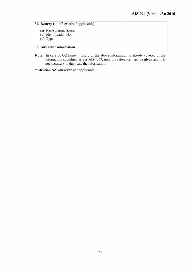
32. Battery cut off switch(if applicable)
(a) Name of manufacturer
(b) Identification No.
(c) Type
33. Any other information
Note: In case of OE fitment, if any of the above information is already covered in the
information submitted as per AIS- 007, only the reference need be given and it is
not necessary to duplicate the information.
* Mention NA wherever not applicable
Page 12
AIS-024 (Version 5): 2016
8/89
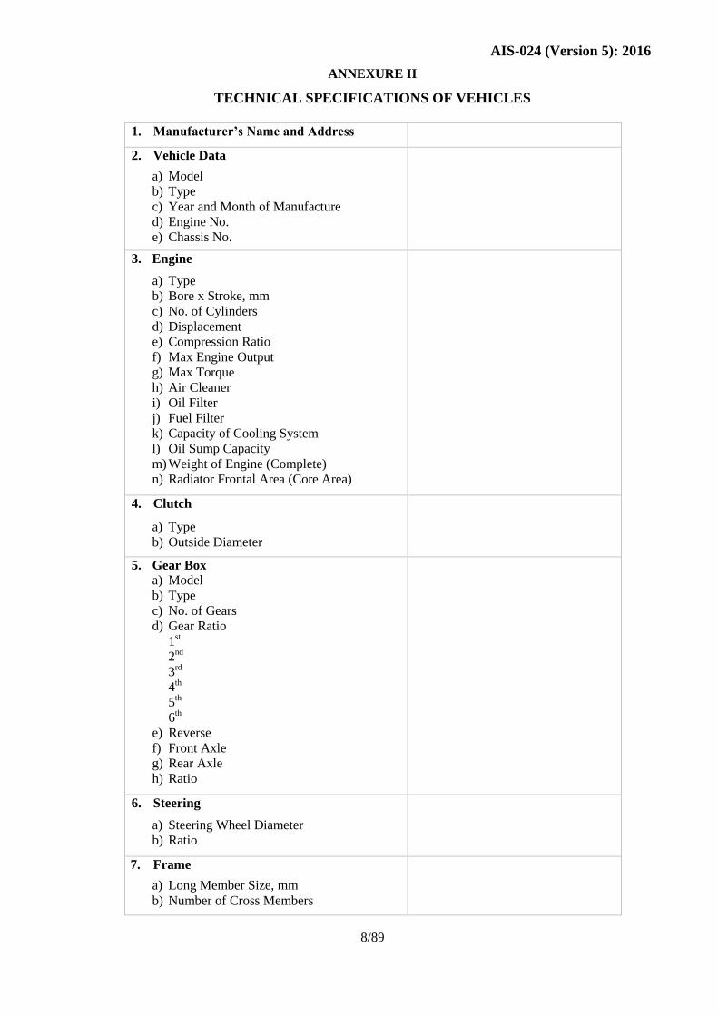
ANNEXURE II
TECHNICAL SPECIFICATIONS OF VEHICLES
1. Manufacturer’s Name and Address
2. Vehicle Data
a) Model
b) Type
c) Year and Month of Manufacture
d) Engine No.
e) Chassis No.
3. Engine
a) Type
b) Bore x Stroke, mm
c) No. of Cylinders
d) Displacement
e) Compression Ratio
f) Max Engine Output
g) Max Torque
h) Air Cleaner
i) Oil Filter
j) Fuel Filter
k) Capacity of Cooling System
l) Oil Sump Capacity
m) Weight of Engine (Complete)
n) Radiator Frontal Area (Core Area)
4. Clutch
a) Type
b) Outside Diameter
5. Gear Box
a) Model
b) Type
c) No. of Gears
d) Gear Ratio
1st
2nd
3rd
4th
5th
6th
e) Reverse
f) Front Axle
g) Rear Axle
h) Ratio
6. Steering
a) Steering Wheel Diameter
b) Ratio
7. Frame
a) Long Member Size, mm
b) Number of Cross Members
Page 13
AIS-024 (Version 5): 2016
9/89
8. Suspension
a) Spring
b) Anti-Roll Bar
9. Shock Absorber
10. Brake
a) Service Brake
b) Front
c) Rear
d) Total Braking Area
e) Parking Brake
f) Wheels and Tyres
11. Electrical System
a) System Voltage
b) Battery
c) Alternator (Max. Output)
d) Type
e) Wiper Motor
12. Fuel Tank
13. Dimensions
a) Wheel Base, mm
b) Overall Width, mm
c) Overall Length, mm
d) Front Track, mm
e) Rear Track, mm
f) Min. Ground Clearance, mm
g) Cargo Box Dimensions
h) Load Body Platform Area
14. Weights
a) Maximum GVW
b) Maximum Permissible FAW
c) Maximum Permissible RAW
d) KERB weight with 90% fuel (with spare
wheel, tools, etc.)
e) Maximum Gradeability in 1st Gear
15. Seating Capacity
Page 14
AIS-024 (Version 5): 2016
10/89
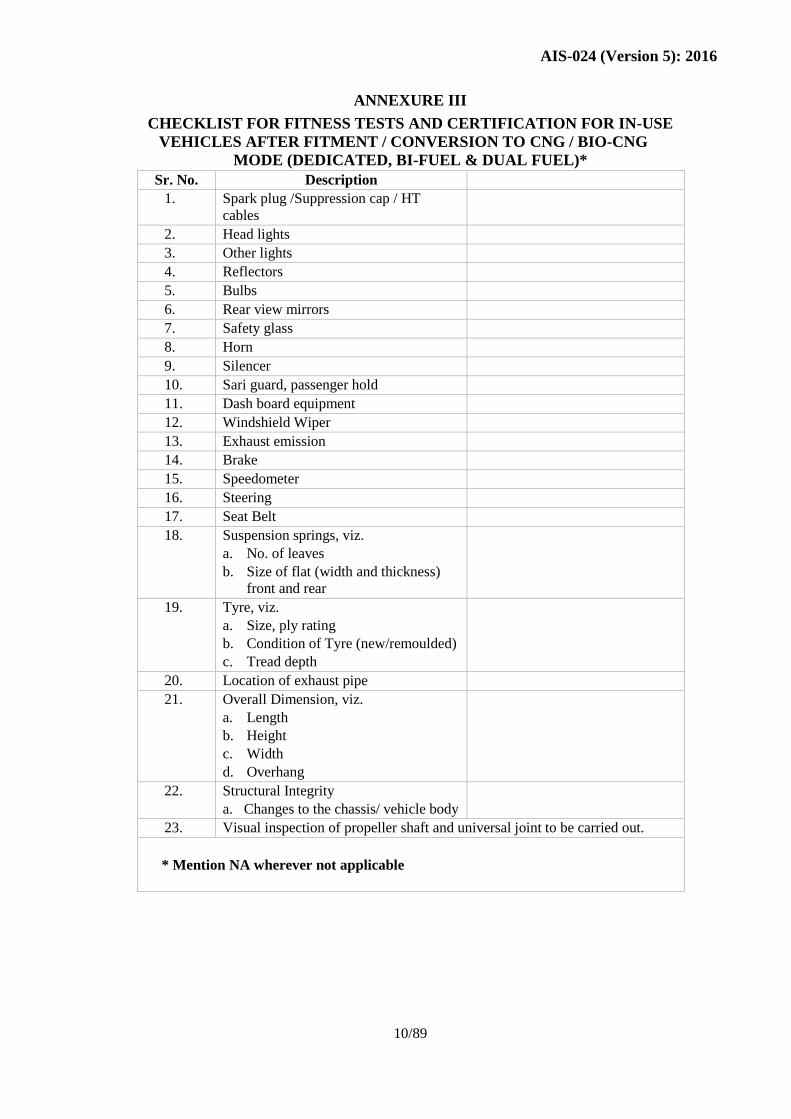
ANNEXURE III
CHECKLIST FOR FITNESS TESTS AND CERTIFICATION FOR IN-USE
VEHICLES AFTER FITMENT / CONVERSION TO CNG / BIO-CNG
MODE (DEDICATED, BI-FUEL & DUAL FUEL)*
Sr. No. Description
1. Spark plug /Suppression cap / HT
cables
2. Head lights
3. Other lights
4. Reflectors
5. Bulbs
6. Rear view mirrors
7. Safety glass
8. Horn
9. Silencer
10. Sari guard, passenger hold
11. Dash board equipment
12. Windshield Wiper
13. Exhaust emission
14. Brake
15. Speedometer
16. Steering
17. Seat Belt
18. Suspension springs, viz.
a. No. of leaves
b. Size of flat (width and thickness)
front and rear
19. Tyre, viz.
a. Size, ply rating
b. Condition of Tyre (new/remoulded)
c. Tread depth
20. Location of exhaust pipe
21. Overall Dimension, viz.
a. Length
b. Height
c. Width
d. Overhang
22. Structural Integrity
a. Changes to the chassis/ vehicle body
23. Visual inspection of propeller shaft and universal joint to be carried out.
* Mention NA wherever not applicable
Page 15
AIS-024 (Version 5): 2016
11/89
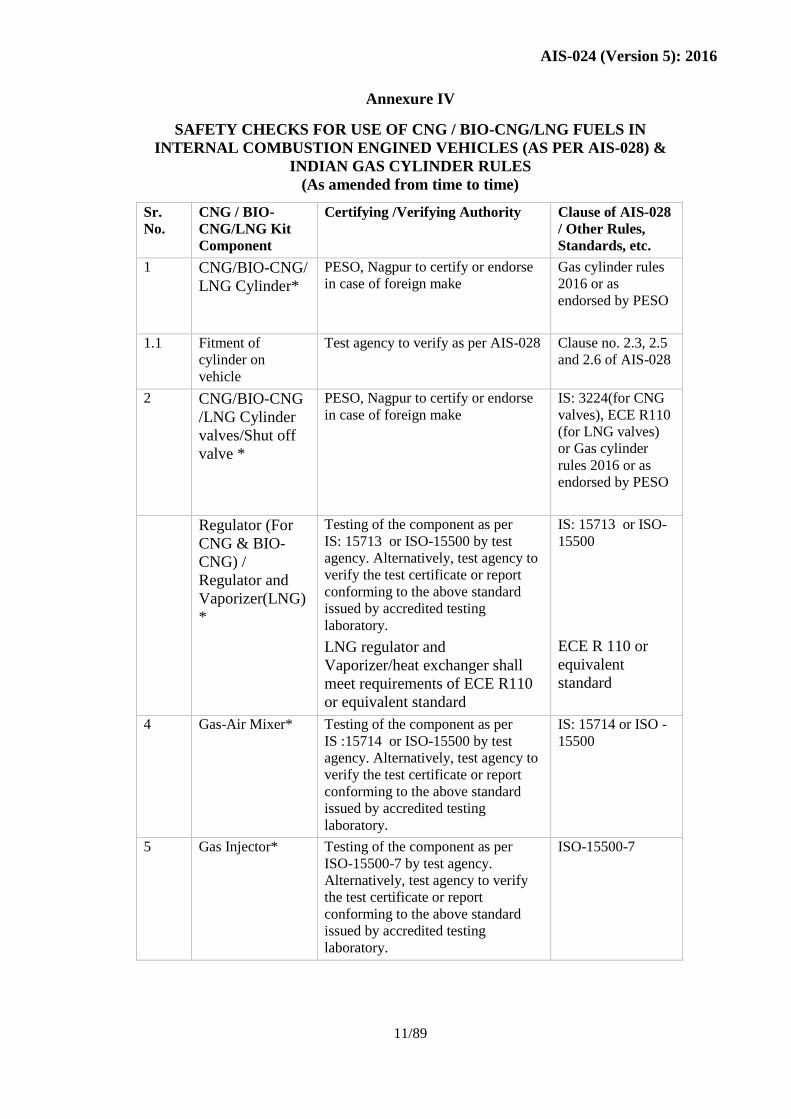
Annexure IV
SAFETY CHECKS FOR USE OF CNG / BIO-CNG/LNG FUELS IN
INTERNAL COMBUSTION ENGINED VEHICLES (AS PER AIS-028) &
INDIAN GAS CYLINDER RULES
(As amended from time to time)
Sr.
No.
CNG / BIO-
CNG/LNG Kit
Component
Certifying /Verifying Authority Clause of AIS-028
/ Other Rules,
Standards, etc.
1 CNG/BIO-CNG/
LNG Cylinder*
PESO, Nagpur to certify or endorse
in case of foreign make
Gas cylinder rules
2016 or as
endorsed by PESO
1.1 Fitment of
cylinder on
vehicle
Test agency to verify as per AIS-028 Clause no. 2.3, 2.5
and 2.6 of AIS-028
2 CNG/BIO-CNG
/LNG Cylinder
valves/Shut off
valve *
PESO, Nagpur to certify or endorse
in case of foreign make
IS: 3224(for CNG
valves), ECE R110
(for LNG valves)
or Gas cylinder
rules 2016 or as
endorsed by PESO
Regulator (For
CNG & BIO-
CNG) /
Regulator and
Vaporizer(LNG)
*
Testing of the component as per
IS: 15713 or ISO-15500 by test
agency. Alternatively, test agency to
verify the test certificate or report
conforming to the above standard
issued by accredited testing
laboratory.
LNG regulator and
Vaporizer/heat exchanger shall
meet requirements of ECE R110
or equivalent standard
IS: 15713 or ISO-
15500
ECE R 110 or
equivalent
standard
4 Gas-Air Mixer* Testing of the component as per
IS :15714 or ISO-15500 by test
agency. Alternatively, test agency to
verify the test certificate or report
conforming to the above standard
issued by accredited testing
laboratory.
IS: 15714 or ISO -
15500
5 Gas Injector* Testing of the component as per
ISO-15500-7 by test agency.
Alternatively, test agency to verify
the test certificate or report
conforming to the above standard
issued by accredited testing
laboratory.
ISO-15500-7
Page 16
AIS-024 (Version 5): 2016
12/89
6 Petrol Solenoid
Valve*
Testing of the component as per IS:
15717 by test agency. Alternatively,
test agency to verify the test
certificate or report conforming to
the above standard issued by
accredited testing laboratory.
IS: 15717
6.1 Gas Solenoid
Valve / Automatic
Shutoff valve*
Testing of the component as per IS:
15712 or ISO-15500 by test agency.
Alternatively, test agency to verify
the test certificate or report
conforming to the above standard
issued by accredited testing
laboratory.
Automatic shutoff valve of LNG
System (which comes in contact
with LNG shall meet
requirements of ECE R110 or
equivalent standards)
IS: 15712 or ISO-
15500
Automatic shutoff
Valve for LNG
System : ECE
R110 or
equivalent
standards
7 Filling Connection
(NZS & NGV-1
type)
LNG receptacle
Installation on vehicle to be checked
by test agency as per AIS-028
LNG receptacle shall meet
requirements of ECE R110 or
equivalent standard
Clauses 2.2.2,
2.2.3, 2.2.4, 2.2.5
and 2.2.6 of
AIS-028
ECE R 110 or
equivalent
standard
8 Ventilation Test agency to verify. Clause 2.4.2 of
AIS-028
9 Testing of
Conduit*
Testing of the component or
verification of certificate or test
report as per IS: 15715 by test
agency.
IS: 15715
10
CNG / BIO-
CNG/LNG fuel
line
10.1 High pressure —
exceeding
100 kPa*
10.1.1 Exceeding 2.15
MPa
-Rigid pipe Testing of the component or
verification of certificate or test
report as per IS: 15716 by test
agency.
LNG rigid pipeline shall meet
requirements of ECE R110 or IS:
15716 or equivalent standard.
IS: 15716
ECE R110 or IS:
15716 or
equivalent
standard.
Page 17
AIS-024 (Version 5): 2016
13/89
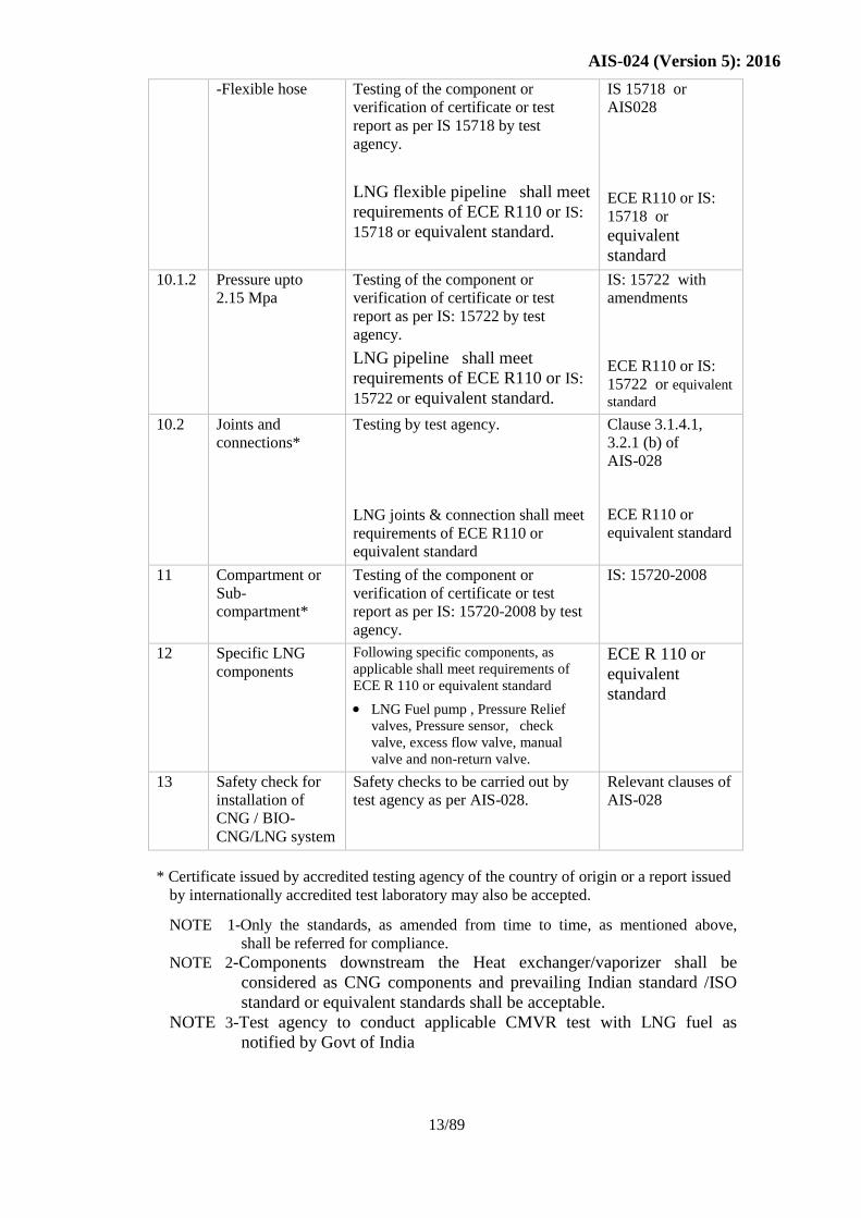
-Flexible hose Testing of the component or
verification of certificate or test
report as per IS 15718 by test
agency.
LNG flexible pipeline shall meet
requirements of ECE R110 or IS:
15718 or equivalent standard.
IS 15718 or
AIS028
ECE R110 or IS:
15718 or
equivalent
standard
10.1.2 Pressure upto
2.15 Mpa
Testing of the component or
verification of certificate or test
report as per IS: 15722 by test
agency.
LNG pipeline shall meet
requirements of ECE R110 or IS:
15722 or equivalent standard.
IS: 15722 with
amendments
ECE R110 or IS:
15722 or equivalent
standard
10.2 Joints and
connections*
Testing by test agency.
LNG joints & connection shall meet
requirements of ECE R110 or
equivalent standard
Clause 3.1.4.1,
3.2.1 (b) of
AIS-028
ECE R110 or
equivalent standard
11 Compartment or
Sub-
compartment*
Testing of the component or
verification of certificate or test
report as per IS: 15720-2008 by test
agency.
IS: 15720-2008
12 Specific LNG
components
Following specific components, as
applicable shall meet requirements of
ECE R 110 or equivalent standard
LNG Fuel pump , Pressure Relief
valves, Pressure sensor, check
valve, excess flow valve, manual
valve and non-return valve.
ECE R 110 or
equivalent
standard
13 Safety check for
installation of
CNG / BIO-
CNG/LNG system
Safety checks to be carried out by
test agency as per AIS-028.
Relevant clauses of
AIS-028
* Certificate issued by accredited testing agency of the country of origin or a report issued
by internationally accredited test laboratory may also be accepted.
NOTE 1-Only the standards, as amended from time to time, as mentioned above,
shall be referred for compliance.
NOTE 2-Components downstream the Heat exchanger/vaporizer shall be
considered as CNG components and prevailing Indian standard /ISO
standard or equivalent standards shall be acceptable.
NOTE 3-Test agency to conduct applicable CMVR test with LNG fuel as
notified by Govt of India
Page 18
AIS-024 (Version 5): 2016
14/96
ANNEXURE V
CRITERIA TO AUTHORIZE THE KIT INSTALLER AND
RESPONSIBILITY OF VEHICLE MANUFACTURER / KIT
MANUFACTURER / SUPPLIER / INSTALLER APPLICABLE TO CNG /
BIO-CNG VEHCILES (DEDICATED/BI-FUEL/DUAL FUEL).
The following are the criteria to be complied by the kit supplier/manufacturer for
conversion of in-use vehicles to operate on CNG / BIO-CNG fuel.
1. The replacement of engine / retrofitment of CNG / BIO-CNG kit shall be type
approved by any one of the testing agencies specified in Rule 126 of the Central Motor
Vehicle Rules. The responsibility of the type approval and ensuring that the kits
manufactured comply with the provisions and installation thereof shall be that of the
vehicle/kit manufacturer/supplier as the case may be.
2. Only the Installer authorized by vehicle/kit manufacturer/supplier shall fit the kit on
vehicles. For this purpose, the vehicle/kit manufacturer/supplier shall issue a
certificate of authorization to the Installer concerned duly authorizing them to fit the
kit on behalf of manufacturer.
3. Kit installer shall be equipped with the following tools and equipment.
Two post lift / ramp
Electric hand drill machine and H.S.S. drill bits
Tube bender
Tube cutter
Deburring tool for tube
Set of ‘D’ ring and box spanners
Set of screw driver (both flat and star)
Set of allen keys
H.S.S. hand saw
Crimping tool for electrical cable termination
Soap bubble bottle
Set letter and number punch
Infrared pollution meter
Timing gun
Filler gauge
Measurement tape
Air compressor
Flame proof inspection light
Vernier caliper
Multimeter
Silicon seal/sealant
Firefighting equipment
Dry chemical powder (DCP) type
Minimum two numbers of 5 kg each with ISI mark.
CO2 type fire extinguisher – minimum 1 number of 5 kg with ISI mark.
Fire buckets – 2 buckets.
Page 19
AIS-024 (Version 5): 2016
15/96
4. Installer shall have trained technicians having minimum ITI qualification and at least
two years of experience in the similar field. Vehicle/kit manufacturer/supplier to
impart extensive training to the technicians on CNG / BIO-CNGkit installation.
5. Installer to display in the premises, authorization certificate issued by vehicle
manufacturer/kit manufacturer/supplier. Also, installer to display details of the
facilities available in terms of equipment and trained manpower.
6. After obtaining the type approval certification, the vehicle/kit manufacturer/supplier(s)
shall authorize the installer to undertake CNG / BIO-CNGconversion, who meets the
following requirements.
i) Name and communication details like address, telephone number, etc. of the
installer.
ii) Business profile
iii) Qualification
iv) Experience
v) Details of technical staff and equipment
vi) Specification of workshop/land use certificate from appropriate authority.
The vehicle / kit manufacturer or supplier shall submit the above information to the
regional transport authorities.
7. Installer to carry out conversion/installation as per “Code of Practice for Use of CNG /
BIO-CNGfuels in internal combustion engined vehicles (AIS-028)”.
8. Installer to carry out the inspection, testing, commissioning & garaging/repair of CNG
/ BIO-CNGsystem as per clause 7 & 8 of AIS-028”.
9. Installer shall issue installation certificate as per Annexure VI of AIS-024, to the
vehicle owner, that the conversion kit has been fitted in safe and proper manner, in
compliance with “Code of Practice for Use of CNG / BIO-CNGfuel in Internal
combustion Engined Vehicles (AIS-028) ”.
10. Installer to send a copy of installation certificate as per Annexure VI of AIS-024 and
duly filled checklist as per “Appendix A of AIS-028 (for vehicles other than CNG /
BIO-CNGbuses) / Annexure VII of AIS-024 (for CNG / BIO-CNGbuses)” to RTO
and Test Agency, who has type approved the CNG / BIO-CNGconversion kit.
11. The record of conversion / alteration of vehicles carried out by the kit installer shall be
maintained and made available to the authorities such as MORTH / Test Agencies /
Transport Authorities as and when demanded.
12. The vehicle owner shall apply to the concerned registering authority within 14 days of
undertaking the alteration, as required under Section 52 of Motor Vehicle Act 1988,
for endorsement of particular alteration in registration certificate mentioning place and
date of installation and installation certificate number. This shall also be ensured by
the kit installer.
13. The vehicle/kit manufacturer or supplier shall impart training to installer on
installation, maintenance and operation of CNG / BIO-CNGsystem and issue the
training certificate to installer after completion of training. The test agency may devise
the appropriate training programme as required.
Page 20
AIS-024 (Version 5): 2016
16/96
The training shall encompass the following:
13.1 CNG / BIO-CNGTank
a) Fitments on tank
b) Location and ventilation of tanks.
c) Construction of compartment and sub-compartment
d) Installation of tank
e) Shielding
13.2 CNG / BIO-CNGFuel Line
a) Testing of CNG / BIO-CNGfuel line
b) Flexibility
c) Installation
13.3 CNG / BIO-CNGControl Equipment
a) Installation of regulator and its functioning
b) Installation of fuel selection switch and its information
13.4 Inspection, Testing and Commissioning of CNG / BIO-CNGSystem
a) Commissioning
b) Leak testing
13.5 Garaging and Repair
a) Repair operation of CNG / BIO-CNGvehicles
b) Scrapping
13.6 Periodic inspection
13.7 CNG / BIO-CNGCharacteristics and Safety Aspects for Handling and Storage
14. The kit installer shall ensure compliance to the emission norms and Sub-rule 2 of
Rule 115 and the code of practice for the use of CNG / BIO-CNGfuel in internal
combustion engined vehicles.
15. Responsibility of the vehicle /kit manufacturer/supplier/installer: The
owner/driver shall be instructed in the correct way the gas system and controls
function along with a owners operation manual for the gas system outlining the
following:
15.1 Basic gas system explanation with a diagram
15.2 Fuel change over switch operation if bi-fuel /Dual fuel system is fitted
15.3 Starting procedure for cold and hot starting
15.4 How the vehicle is refueled
15.5 In the event of backfiring check procedure
15.6 In the event of a gas leak shut off procedure
15.7 Emergence or information contact numbers
Page 21
AIS-024 (Version 5): 2016
17/96
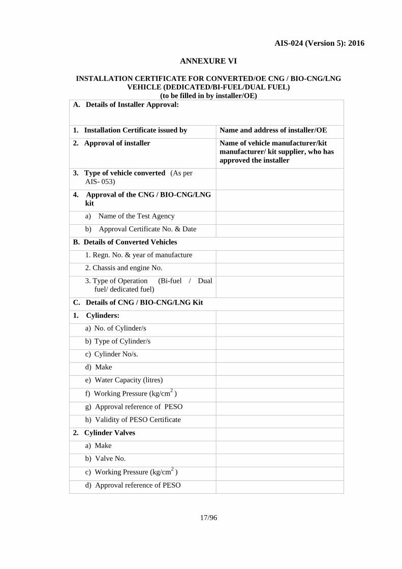
ANNEXURE VI
INSTALLATION CERTIFICATE FOR CONVERTED/OE CNG / BIO-CNG/LNG
VEHICLE (DEDICATED/BI-FUEL/DUAL FUEL)
(to be filled in by installer/OE)
A. Details of Installer Approval:
1. Installation Certificate issued by Name and address of installer/OE
2. Approval of installer Name of vehicle manufacturer/kit
manufacturer/ kit supplier, who has
approved the installer
3. Type of vehicle converted (As per
AIS- 053)
4. Approval of the CNG / BIO-CNG/LNG
kit
a) Name of the Test Agency
b) Approval Certificate No. & Date
B. Details of Converted Vehicles
1. Regn. No. & year of manufacture
2. Chassis and engine No.
3. Type of Operation (Bi-fuel / Dual
fuel/ dedicated fuel)
C. Details of CNG / BIO-CNG/LNG Kit
1. Cylinders:
a) No. of Cylinder/s
b) Type of Cylinder/s
c) Cylinder No/s.
d) Make
e) Water Capacity (litres)
f) Working Pressure (kg/cm2
)
g) Approval reference of PESO
h) Validity of PESO Certificate
2. Cylinder Valves
a) Make
b) Valve No.
c) Working Pressure (kg/cm2
)
d) Approval reference of PESO
Page 22
AIS-024 (Version 5): 2016
18/96
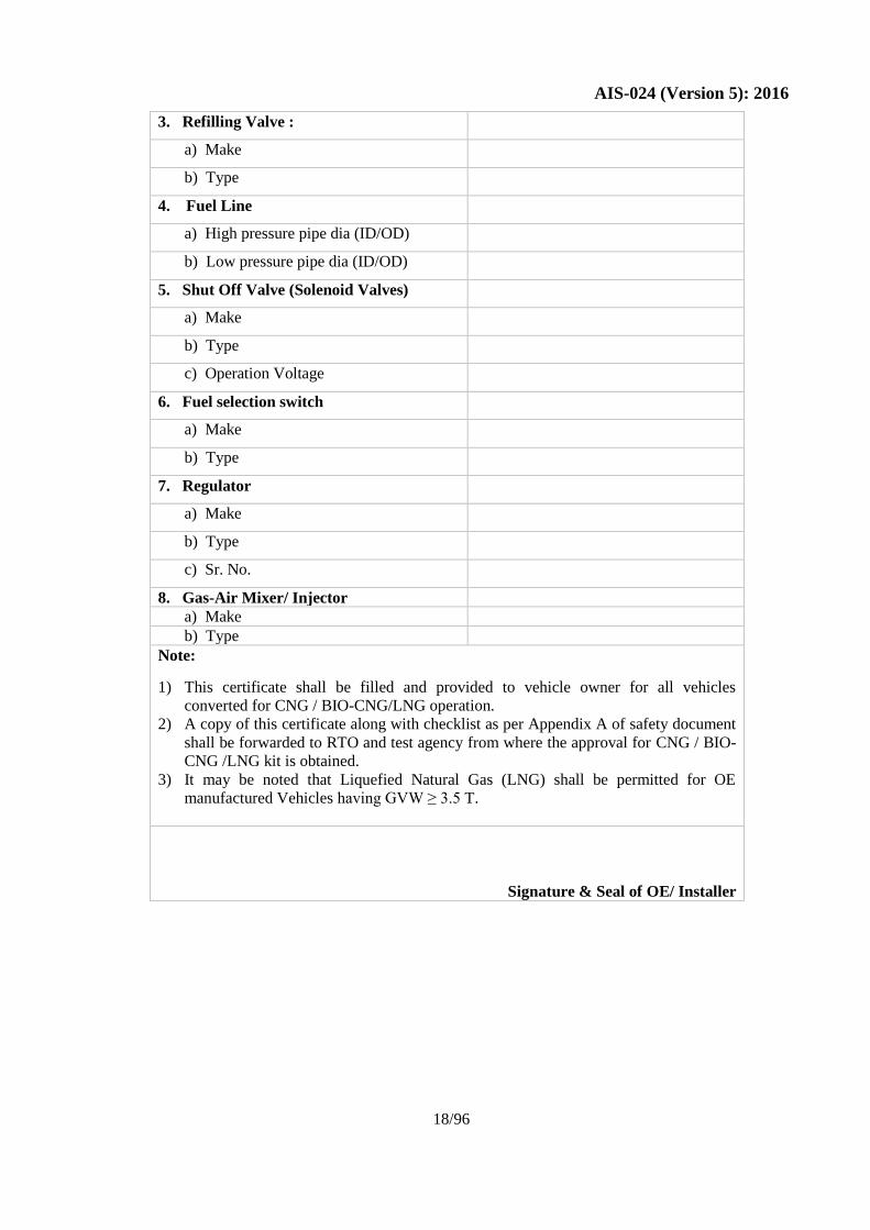
3. Refilling Valve :
a) Make
b) Type
4. Fuel Line
a) High pressure pipe dia (ID/OD)
b) Low pressure pipe dia (ID/OD)
5. Shut Off Valve (Solenoid Valves)
a) Make
b) Type
c) Operation Voltage
6. Fuel selection switch
a) Make
b) Type
7. Regulator
a) Make
b) Type
c) Sr. No.
8. Gas-Air Mixer/ Injector
a) Make
b) Type
Note:
1) This certificate shall be filled and provided to vehicle owner for all vehicles
converted for CNG / BIO-CNG/LNG operation.
2) A copy of this certificate along with checklist as per Appendix A of safety document
shall be forwarded to RTO and test agency from where the approval for CNG / BIO-
CNG /LNG kit is obtained.
3) It may be noted that Liquefied Natural Gas (LNG) shall be permitted for OE
manufactured Vehicles having GVW ≥ 3.5 T.
Signature & Seal of OE/ Installer
Page 23
AIS-024 (Version 5): 2016
19/96
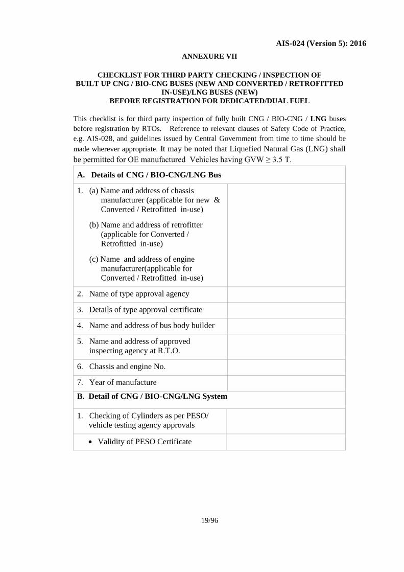
ANNEXURE VII
CHECKLIST FOR THIRD PARTY CHECKING / INSPECTION OF
BUILT UP CNG / BIO-CNG BUSES (NEW AND CONVERTED / RETROFITTED
IN-USE)/LNG BUSES (NEW)
BEFORE REGISTRATION FOR DEDICATED/DUAL FUEL
This checklist is for third party inspection of fully built CNG / BIO-CNG / LNG buses
before registration by RTOs. Reference to relevant clauses of Safety Code of Practice,
e.g. AIS-028, and guidelines issued by Central Government from time to time should be
made wherever appropriate. It may be noted that Liquefied Natural Gas (LNG) shall
be permitted for OE manufactured Vehicles having GVW ≥ 3.5 T.
A. Details of CNG / BIO-CNG/LNG Bus
1. (a) Name and address of chassis
manufacturer (applicable for new &
Converted / Retrofitted in-use)
(b) Name and address of retrofitter
(applicable for Converted /
Retrofitted in-use)
(c) Name and address of engine
manufacturer(applicable for
Converted / Retrofitted in-use)
2. Name of type approval agency
3. Details of type approval certificate
4. Name and address of bus body builder
5. Name and address of approved
inspecting agency at R.T.O.
6. Chassis and engine No.
7. Year of manufacture
B. Detail of CNG / BIO-CNG/LNG System
1. Checking of Cylinders as per PESO/
vehicle testing agency approvals
Validity of PESO Certificate
Page 24
AIS-024 (Version 5): 2016
20/96
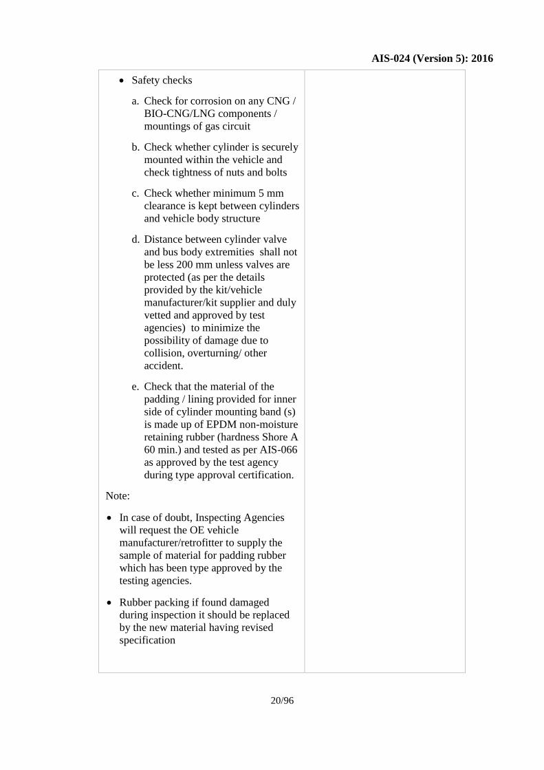
Safety checks
a. Check for corrosion on any CNG /
BIO-CNG/LNG components /
mountings of gas circuit
b. Check whether cylinder is securely
mounted within the vehicle and
check tightness of nuts and bolts
c. Check whether minimum 5 mm
clearance is kept between cylinders
and vehicle body structure
d. Distance between cylinder valve
and bus body extremities shall not
be less 200 mm unless valves are
protected (as per the details
provided by the kit/vehicle
manufacturer/kit supplier and duly
vetted and approved by test
agencies) to minimize the
possibility of damage due to
collision, overturning/ other
accident.
e. Check that the material of the
padding / lining provided for inner
side of cylinder mounting band (s)
is made up of EPDM non-moisture
retaining rubber (hardness Shore A
60 min.) and tested as per AIS-066
as approved by the test agency
during type approval certification.
Note:
In case of doubt, Inspecting Agencies
will request the OE vehicle
manufacturer/retrofitter to supply the
sample of material for padding rubber
which has been type approved by the
testing agencies.
Rubber packing if found damaged
during inspection it should be replaced
by the new material having revised
specification
Page 25
AIS-024 (Version 5): 2016
21/96
2. Cylinder Valves
a. Check specific type & model
approved by Vehicle testing agency
for the vehicle under inspection.
b. Check for operation
c. Check for Shield / protection
d. Check for physical damage to valves
e. Check for burst disc with fusible plug
as approved by PESO (NA for LNG)
f. Leak test using non corrosive
foaming agent(e.g. snoop of M/s
Swagelok, collin etc) or Methane
leak detector
3. Refilling Valve
Safety checks -
a. Check for dust cap / plug
b. Check that engine should not start
when dust cap / plug is removed
or open (NA for LNG)
Check for proper make & type of
interlocking switch as approved by
testing agencies. (NA for LNG)
Check leakage for non-return valve
using non-corrosive foaming agent
(i.e. snoop of M/s Swagelok, collin
etc.) or Methane leak detector.
4. Fuel Line
Safety checks
a. Check for corrosion, damage on
CNG / BIO-CNG/LNG fuel line
(In case of PVC sleeved fuel line,
corrosion shall be inspected at the
ends, wherever it is exposed. Also
inspect for any damage to the
sleeving. Sleeve should be firmly
gripped to the CNG / BIO-
CNG/LNG fuel line)
Page 26
AIS-024 (Version 5): 2016
22/96
b. Check whether fuel line is
securely mounted
c. Check for deformation of U and
Pigtail bends provided in high
pressure piping for flexibility as
per approved layout
d. Distance between fuel line and
exhaust pipe / shield shall not be
less than 75 mm and the fuel line
should also be properly clamped
and routed so as not to touch the
engine block
e. Check whether effective
protection is provided, as per
approved layout, to prevent the
possibility of damage due to loose
objects from road.
f. Check the distance between any
two clips which shall not be more
than 600 mm
g. Leak test using non-corrosive
foaming agent (i.e. snoop of M/s
Swagelok, collin etc.) or methane
leak detector
5. Shut Off Valve (Solenoid Valve(s))
wherever separately provided
Safety checks
a. Verify the following as per type
approval specification
Make
Type (if applicable)
Identification No.
b. Check whether shut off valve is
securely mounted
c. Check operation for “Close &
Open” as required
d. Leak test using non-corrosive
foaming agent (i.e. snoop of M/s
Swagelok, Collin etc.) or
methane leak detector
Page 27
AIS-024 (Version 5): 2016
23/96
6. Regulator
Safety checks
a. Verify the following as per type
approval specification
Make
Type (if applicable)
Identification No.
b. Check whether regulator is
securely mounted
c. Leak test using non-corrosive
foaming agent(i.e. snoop of M/s
Swagelok, collin etc.) or
methane leak detector
7. Heat exchanger Vaporizer(LNG)
Safety checks
a. Verify the following as per type
approval specification
Make
Type (if applicable)
Identification No.
b. Check whether regulator is
securely mounted
c. Leak test using non-corrosive
foaming agent(i.e. snoop of M/s
Swagelok, collin etc.) or
methane leak detector
8. Gas-Air Mixer
Page 28
AIS-024 (Version 5): 2016
24/96
Safety checks
a. Verify the following as per type
approval specification
Make
Type (if applicable)
Identification No.
b. Check whether gas-air mixer is
securely mounted
c. Leak test using non-corrosive
foaming agent(i.e. snoop of M/s
Swagelok, collin etc.) or
methane leak detector
9. Electrical wiring: Safety checks
9.1 For OE & Converted / Retrofitted
In-Use Vehicles
a. Check whether that current limiting
device (fuse) is fitted as per
manufacturer specifications and make
b. Terminals are insulated to prevent
shorting
c. Wiring are taped and clipped with
loom & mounted securely.
d. Battery shall be securely mounted and
battery terminal shall be locked
properly by means of suitable nut &
bolt with washers.
e. Check installation of battery cut-off
switch as per chassis manufacturer’s
recommendations. Location of Battery
cut-off switch should be within the
reach of driver in seating posture in
driving seat.
f. Check routing of high tension cable to
avoid accidental earthing and to be
placed away from any heat source –
as per chassis manufacturer’s
recommendations/ layout
g. Check for proper make of high
tension cable as per chassis
manufacturer’s recommendation as
well as check for tight fitment of its
terminal to the spark-plug
Page 29
AIS-024 (Version 5): 2016
25/96
9.2 FOR OE VEHICLES
a. Check wiring harness layout under the
floor and in the engine compartment to
be in accordance with chassis
manufacturer’s layout / specifications /
approval
b. Check wiring harness in cabin and
passenger compartment to be as per
chassis manufacturer’s guidelines /
approval
c. Cable harness has to be as per the
recommendations of OE chassis/ vehicle
manufacturers
9.3 FOR CONVERTED / RETROFITTED
IN-USE VEHICLES
Check wiring harness layout under the floor /
cabin and passenger compartment for proper
sleeving and routing in order to avoid
accidental sparking.
10. Service shut-off valve:
Safety checks -
a. Make & type
b. Check operation
c. Check whether service shut off valve
is securely mounted
d. Leak test using non-corrosive foaming
agent (i.e. snoop of M/s Swagelok,
collin etc.) or methane leak detector
11. CNG / BIO-CNG/LNG Filter:
a. Check whether CNG / BIO-CNG/LNG
filter is securely mounted
b. Leak test using non-corrosive foaming
agent (i.e. snoop of M/s Swagelok, collin
etc.) or methane leak detector
12. CNG / BIO-CNG Pressure Gauge /
Content Gauge in case of LNG :
a. Make & type
b. Check whether CNG / BIO-CNG pressure
indicator / LNG content gauge is
securely mounted
c. Leak test using non-corrosive foaming
agent (i.e. snoop of M/s Swagelok, collin
etc.) or methane leak detector
Page 30
AIS-024 (Version 5): 2016
26/96
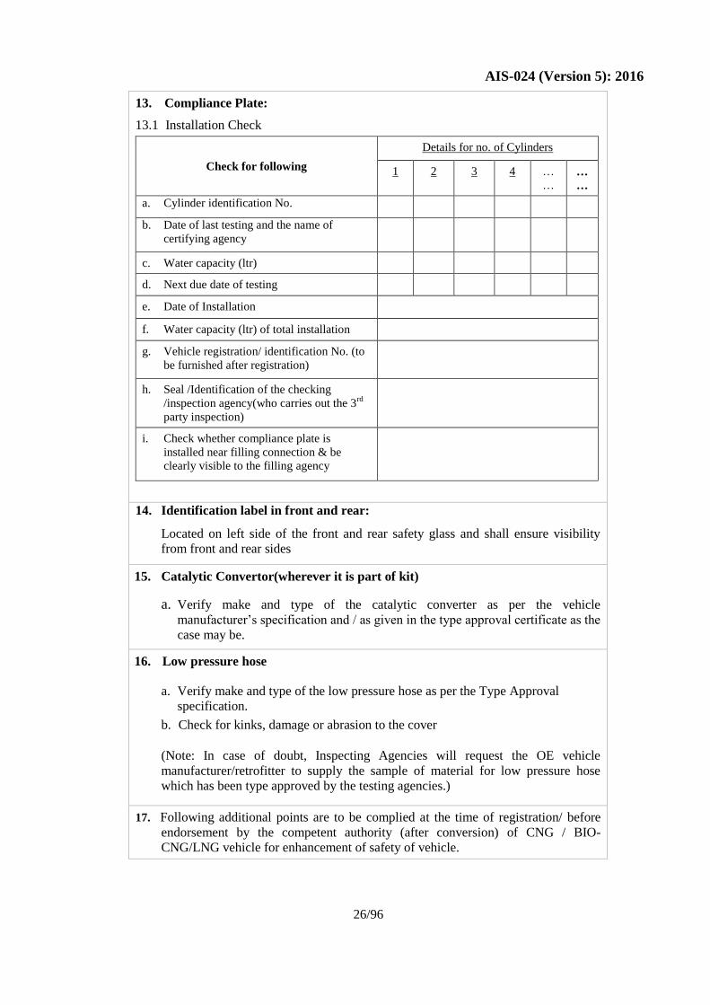
13. Compliance Plate:
13.1 Installation Check
Check for following
Details for no. of Cylinders
1 2 3 4 …
… …
…
a. Cylinder identification No.
b. Date of last testing and the name of
certifying agency
c. Water capacity (ltr)
d. Next due date of testing
e. Date of Installation
f. Water capacity (ltr) of total installation
g. Vehicle registration/ identification No. (to
be furnished after registration)
h. Seal /Identification of the checking
/inspection agency(who carries out the 3rd
party inspection)
i. Check whether compliance plate is
installed near filling connection & be
clearly visible to the filling agency
14. Identification label in front and rear:
Located on left side of the front and rear safety glass and shall ensure visibility
from front and rear sides
15. Catalytic Convertor(wherever it is part of kit)
a. Verify make and type of the catalytic converter as per the vehicle
manufacturer’s specification and / as given in the type approval certificate as the
case may be.
16. Low pressure hose
a. Verify make and type of the low pressure hose as per the Type Approval
specification.
b. Check for kinks, damage or abrasion to the cover
(Note: In case of doubt, Inspecting Agencies will request the OE vehicle
manufacturer/retrofitter to supply the sample of material for low pressure hose
which has been type approved by the testing agencies.)
17. Following additional points are to be complied at the time of registration/ before
endorsement by the competent authority (after conversion) of CNG / BIO-
CNG/LNG vehicle for enhancement of safety of vehicle.
Page 31
AIS-024 (Version 5): 2016
27/96
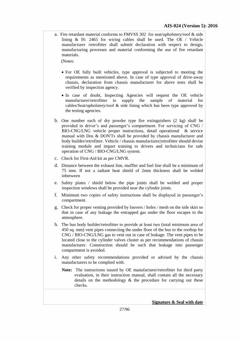
a. Fire retardant material conforms to FMVSS 302 for seat/upholstery/roof & side
lining & IS: 2465 for wiring cables shall be used. The OE / Vehicle
manufacturer /retrofitter shall submit declaration with respect to design,
manufacturing processes and material conforming the use of fire retardant
materials.
(Notes:
For OE fully built vehicles, type approval is subjected to meeting the
requirements as mentioned above. In case of type approval of drive-away
chassis, declaration from chassis manufacturer for above tests shall be
verified by inspection agency.
In case of doubt, Inspecting Agencies will request the OE vehicle
manufacturer/retrofitter to supply the sample of material for
cables/Seat/upholstery/roof & side lining which has been type approved by
the testing agencies.
b. One number each of dry powder type fire extinguishers (2 kg) shall be
provided in driver’s and passenger’s compartment. For servicing of CNG /
BIO-CNG/LNG vehicle proper instructions, detail operational & service
manual with Dos & DON'Ts shall be provided by chassis manufacturer and
body builder/retrofitter. Vehicle / chassis manufacturer/retrofitter should devise
training module and impart training to drivers and technicians for safe
operation of CNG / BIO-CNG/LNG system.
c. Check for First-Aid kit as per CMVR.
d. Distance between the exhaust line, muffler and fuel line shall be a minimum of
75 mm. If not a radiant heat shield of 2mm thickness shall be welded
inbetween
e. Safety plates / shield below the pipe joints shall be welded and proper
inspection windows shall be provided near the cylinder joints.
f. Minimum two copies of safety instructions shall be displayed in passenger’s
compartment.
g. Check for proper venting provided by louvers / holes / mesh on the side skirt so
that in case of any leakage the entrapped gas under the floor escapes to the
atmosphere.
h. The bus body builder/retrofitter to provide at least two (total minimum area of
450 sq. mm) vent pipes connecting the under floor of the bus to the rooftop for
CNG / BIO-CNG/LNG gas to vent out in case of leakage. The vent pipes to be
located close to the cylinder valves cluster as per recommendations of chassis
manufacturer. Construction should be such that leakage into passenger
compartment is avoided.
i. Any other safety recommendations provided or advised by the chassis
manufacturers to be complied with.
Note: The instructions issued by OE manufacturer/retrofitter for third party
evaluation, in their instruction manual, shall contain all the necessary
details on the methodology & the procedure for carrying out these
checks.
Signature & Seal with date
Page 32
AIS-024 (Version 5): 2016
28/96
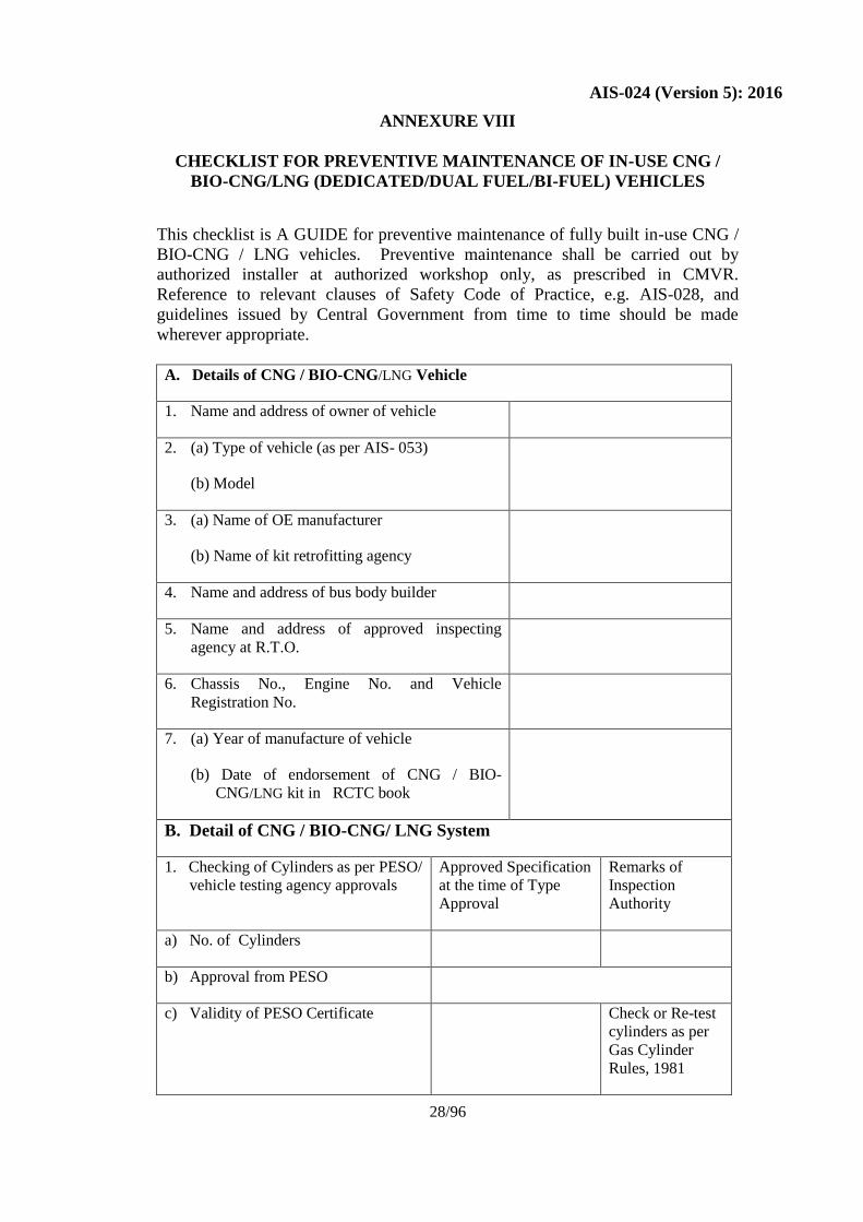
ANNEXURE VIII
CHECKLIST FOR PREVENTIVE MAINTENANCE OF IN-USE CNG /
BIO-CNG/LNG (DEDICATED/DUAL FUEL/BI-FUEL) VEHICLES
This checklist is A GUIDE for preventive maintenance of fully built in-use CNG /
BIO-CNG / LNG vehicles. Preventive maintenance shall be carried out by
authorized installer at authorized workshop only, as prescribed in CMVR.
Reference to relevant clauses of Safety Code of Practice, e.g. AIS-028, and
guidelines issued by Central Government from time to time should be made
wherever appropriate.
A. Details of CNG / BIO-CNG/LNG Vehicle
1. Name and address of owner of vehicle
2. (a) Type of vehicle (as per AIS- 053)
(b) Model
3. (a) Name of OE manufacturer
(b) Name of kit retrofitting agency
4. Name and address of bus body builder
5. Name and address of approved inspecting
agency at R.T.O.
6. Chassis No., Engine No. and Vehicle
Registration No.
7. (a) Year of manufacture of vehicle
(b) Date of endorsement of CNG / BIO-
CNG/LNG kit in RCTC book
B. Detail of CNG / BIO-CNG/ LNG System
1. Checking of Cylinders as per PESO/
vehicle testing agency approvals
Approved Specification
at the time of Type
Approval
Remarks of
Inspection
Authority
a) No. of Cylinders
b) Approval from PESO
c) Validity of PESO Certificate Check or Re-test
cylinders as per
Gas Cylinder
Rules, 1981
Page 33
AIS-024 (Version 5): 2016
29/96
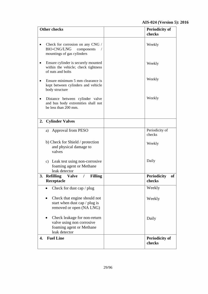
Other checks
Periodicity of
checks
Check for corrosion on any CNG /
BIO-CNG/LNG components /
mountings of gas cylinders
Ensure cylinder is securely mounted
within the vehicle; check tightness
of nuts and bolts
Ensure minimum 5 mm clearance is
kept between cylinders and vehicle
body structure
Distance between cylinder valve
and bus body extremities shall not
be less than 200 mm.
Weekly
Weekly
Weekly
Weekly
2. Cylinder Valves
a) Approval from PESO
b) Check for Shield / protection
and physical damage to
valves
c) Leak test using non-corrosive
foaming agent or Methane
leak detector
Periodicity of
checks
Weekly
Daily
3. Refilling Valve / Filling
Receptacle
Periodicity of
checks
Check for dust cap / plug
Check that engine should not
start when dust cap / plug is
removed or open (NA LNG)
Check leakage for non-return
valve using non corrosive
foaming agent or Methane
leak detector
Weekly
Weekly
Daily
4. Fuel Line Periodicity of
checks
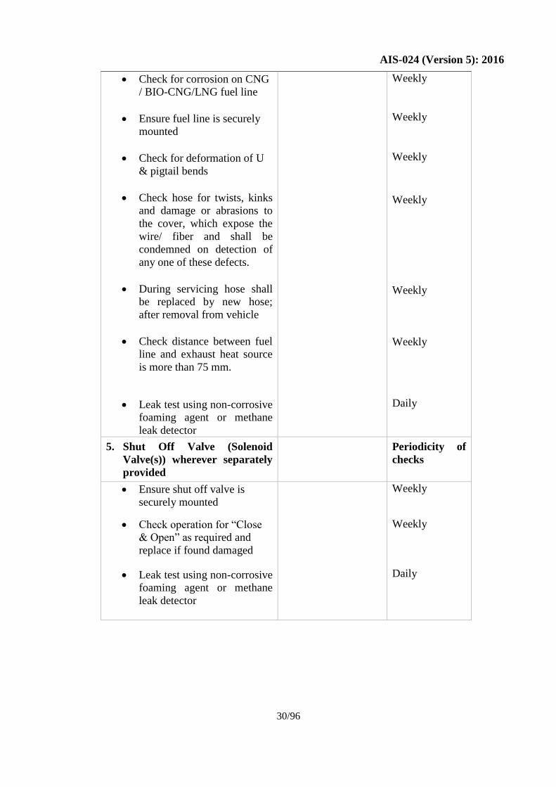
Page 34
AIS-024 (Version 5): 2016
30/96
Check for corrosion on CNG
/ BIO-CNG/LNG fuel line
Ensure fuel line is securely
mounted
Check for deformation of U
& pigtail bends
Check hose for twists, kinks
and damage or abrasions to
the cover, which expose the
wire/ fiber and shall be
condemned on detection of
any one of these defects.
During servicing hose shall
be replaced by new hose;
after removal from vehicle
Check distance between fuel
line and exhaust heat source
is more than 75 mm.
Leak test using non-corrosive
foaming agent or methane
leak detector
Weekly
Weekly
Weekly
Weekly
Weekly
Weekly
Daily
5. Shut Off Valve (Solenoid
Valve(s)) wherever separately
provided
Periodicity of
checks
Ensure shut off valve is
securely mounted
Check operation for “Close
& Open” as required and
replace if found damaged
Leak test using non-corrosive
foaming agent or methane
leak detector
Weekly
Weekly
Daily
Page 35
AIS-024 (Version 5): 2016
31/96
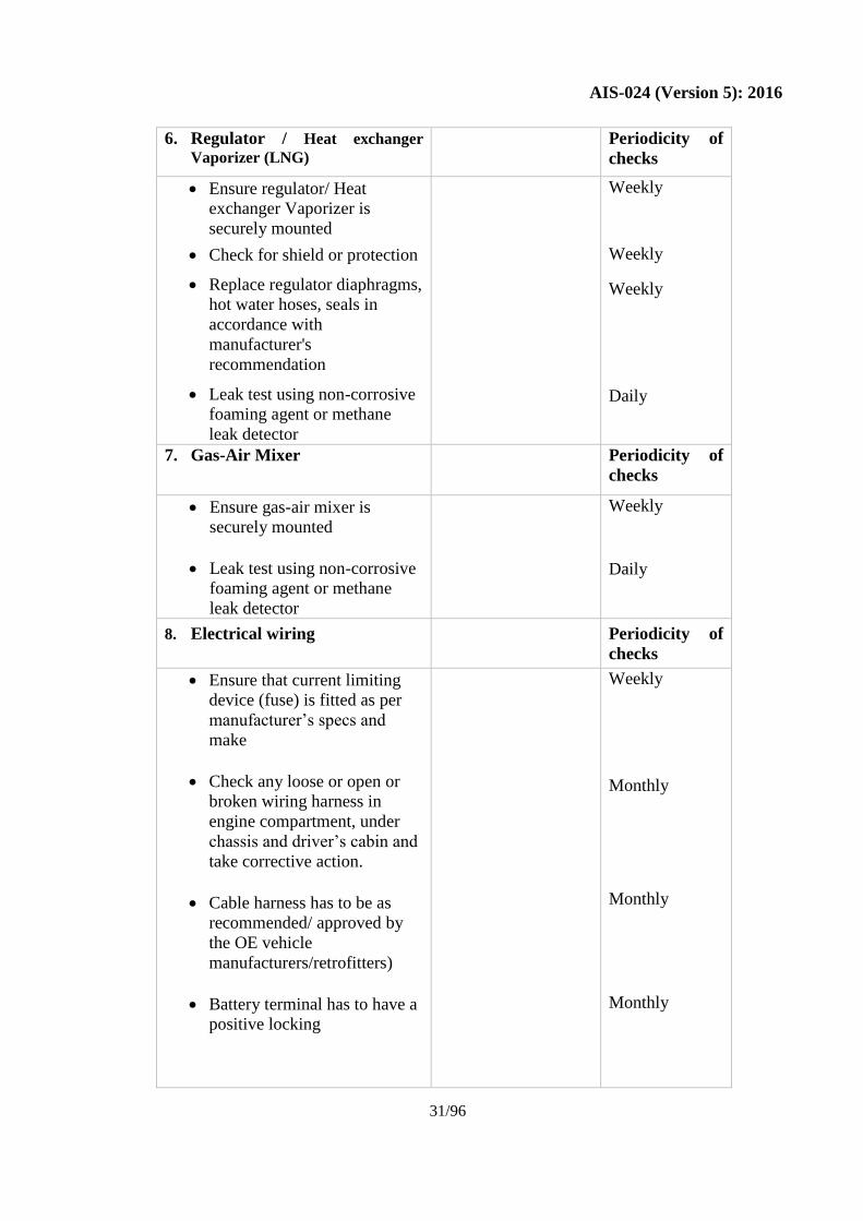
6. Regulator / Heat exchanger
Vaporizer (LNG) Periodicity of
checks
Ensure regulator/ Heat
exchanger Vaporizer is
securely mounted
Check for shield or protection
Replace regulator diaphragms,
hot water hoses, seals in
accordance with
manufacturer's
recommendation
Leak test using non-corrosive
foaming agent or methane
leak detector
Weekly
Weekly
Weekly
Daily
7. Gas-Air Mixer Periodicity of
checks
Ensure gas-air mixer is
securely mounted
Leak test using non-corrosive
foaming agent or methane
leak detector
Weekly
Daily
8. Electrical wiring Periodicity of
checks
Ensure that current limiting
device (fuse) is fitted as per
manufacturer’s specs and
make
Check any loose or open or
broken wiring harness in
engine compartment, under
chassis and driver’s cabin and
take corrective action.
Cable harness has to be as
recommended/ approved by
the OE vehicle
manufacturers/retrofitters)
Battery terminal has to have a
positive locking
Weekly
Monthly
Monthly
Monthly
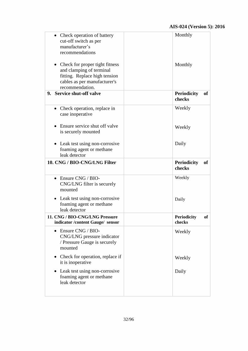
Page 36
AIS-024 (Version 5): 2016
32/96
Check operation of battery
cut-off switch as per
manufacturer’s
recommendations
Check for proper tight fitness
and clamping of terminal
fitting. Replace high tension
cables as per manufacturer's
recommendation.
Monthly
Monthly
9. Service shut-off valve Periodicity of
checks
Check operation, replace in
case inoperative
Ensure service shut off valve
is securely mounted
Leak test using non-corrosive
foaming agent or methane
leak detector
Weekly
Weekly
Daily
10. CNG / BIO-CNG/LNG Filter
Periodicity of
checks
Ensure CNG / BIO-
CNG/LNG filter is securely
mounted
Leak test using non-corrosive
foaming agent or methane
leak detector
Weekly
Daily
11. CNG / BIO-CNG/LNG Pressure
indicator /content Gauge/ sensor
Periodicity of
checks
Ensure CNG / BIO-
CNG/LNG pressure indicator
/ Pressure Gauge is securely
mounted
Check for operation, replace if
it is inoperative
Leak test using non-corrosive
foaming agent or methane
leak detector
Weekly
Weekly
Daily
Page 37
AIS-024 (Version 5): 2016
33/96
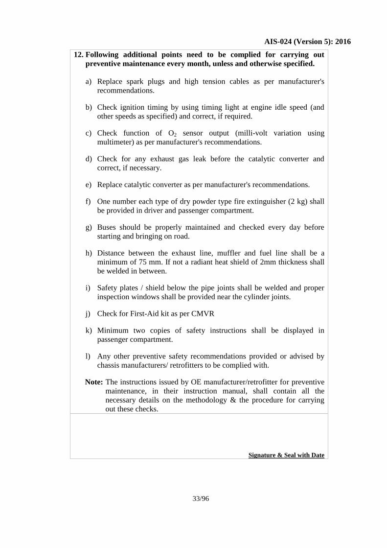
12. Following additional points need to be complied for carrying out
preventive maintenance every month, unless and otherwise specified.
a) Replace spark plugs and high tension cables as per manufacturer's
recommendations.
b) Check ignition timing by using timing light at engine idle speed (and
other speeds as specified) and correct, if required.
c) Check function of O2 sensor output (milli-volt variation using
multimeter) as per manufacturer's recommendations.
d) Check for any exhaust gas leak before the catalytic converter and
correct, if necessary.
e) Replace catalytic converter as per manufacturer's recommendations.
f) One number each type of dry powder type fire extinguisher (2 kg) shall
be provided in driver and passenger compartment.
g) Buses should be properly maintained and checked every day before
starting and bringing on road.
h) Distance between the exhaust line, muffler and fuel line shall be a
minimum of 75 mm. If not a radiant heat shield of 2mm thickness shall
be welded in between.
i) Safety plates / shield below the pipe joints shall be welded and proper
inspection windows shall be provided near the cylinder joints.
j) Check for First-Aid kit as per CMVR
k) Minimum two copies of safety instructions shall be displayed in
passenger compartment.
l) Any other preventive safety recommendations provided or advised by
chassis manufacturers/ retrofitters to be complied with.
Note: The instructions issued by OE manufacturer/retrofitter for preventive
maintenance, in their instruction manual, shall contain all the
necessary details on the methodology & the procedure for carrying
out these checks.
Signature & Seal with Date
Page 38
AIS-024 (Version 5): 2016
34/96
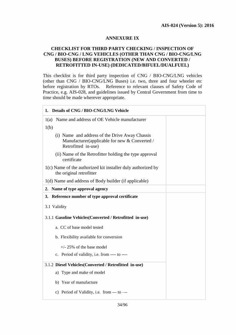
ANNEXURE IX
CHECKLIST FOR THIRD PARTY CHECKING / INSPECTION OF
CNG / BIO-CNG / LNG VEHICLES (OTHER THAN CNG / BIO-CNG/LNG
BUSES) BEFORE REGISTRATION (NEW AND CONVERTED /
RETROFITTED IN-USE) (DEDICATED/BIFUEL/DUALFUEL)
This checklist is for third party inspection of CNG / BIO-CNG/LNG vehicles
(other than CNG / BIO-CNG/LNG Buses) i.e. two, three and four wheeler etc
before registration by RTOs. Reference to relevant clauses of Safety Code of
Practice, e.g. AIS-028, and guidelines issued by Central Government from time to
time should be made wherever appropriate.
1. Details of CNG / BIO-CNG/LNG Vehicle
1(a) Name and address of OE Vehicle manufacturer
1(b)
(i) Name and address of the Drive Away Chassis
Manufacturer(applicable for new & Converted /
Retrofitted in-use)
(ii) Name of the Retrofitter holding the type approval
certificate
1(c) Name of the authorized kit installer duly authorized by
the original retrofitter
1(d) Name and address of Body builder (if applicable)
2. Name of type approval agency
3. Reference number of type approval certificate
3.1 Validity
3.1.1 Gasoline Vehicles(Converted / Retrofitted in-use)
a. CC of base model tested
b. Flexibility available for conversion
+/- 25% of the base model
c. Period of validity, i.e. from ---- to ----
3.1.2 Diesel Vehicles(Converted / Retrofitted in-use)
a) Type and make of model
b) Year of manufacture
c) Period of Validity, i.e. from --- to –--
Page 39
AIS-024 (Version 5): 2016
35/96
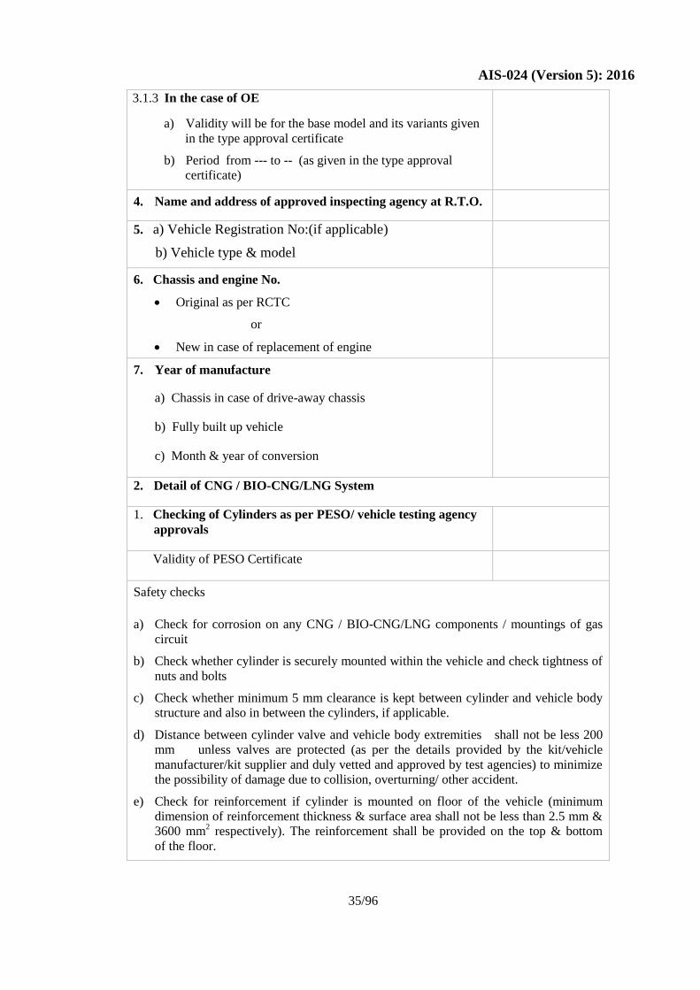
3.1.3 In the case of OE
a) Validity will be for the base model and its variants given
in the type approval certificate
b) Period from --- to -- (as given in the type approval
certificate)
4. Name and address of approved inspecting agency at R.T.O.
5. a) Vehicle Registration No:(if applicable)
b) Vehicle type & model
6. Chassis and engine No.
Original as per RCTC
or
New in case of replacement of engine
7. Year of manufacture
a) Chassis in case of drive-away chassis
b) Fully built up vehicle
c) Month & year of conversion
2. Detail of CNG / BIO-CNG/LNG System
1. Checking of Cylinders as per PESO/ vehicle testing agency
approvals
Validity of PESO Certificate
Safety checks
a) Check for corrosion on any CNG / BIO-CNG/LNG components / mountings of gas
circuit
b) Check whether cylinder is securely mounted within the vehicle and check tightness of
nuts and bolts
c) Check whether minimum 5 mm clearance is kept between cylinder and vehicle body
structure and also in between the cylinders, if applicable.
d) Distance between cylinder valve and vehicle body extremities shall not be less 200
mm unless valves are protected (as per the details provided by the kit/vehicle
manufacturer/kit supplier and duly vetted and approved by test agencies) to minimize
the possibility of damage due to collision, overturning/ other accident.
e) Check for reinforcement if cylinder is mounted on floor of the vehicle (minimum
dimension of reinforcement thickness & surface area shall not be less than 2.5 mm &
3600 mm2 respectively). The reinforcement shall be provided on the top & bottom
of the floor.
Page 40
AIS-024 (Version 5): 2016
36/96
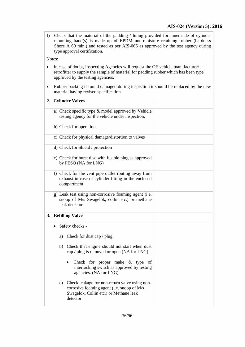
f) Check that the material of the padding / lining provided for inner side of cylinder
mounting band(s) is made up of EPDM non-moisture retaining rubber (hardness
Shore A 60 min.) and tested as per AIS-066 as approved by the test agency during
type approval certification.
Notes:
In case of doubt, Inspecting Agencies will request the OE vehicle manufacturer/
retrofitter to supply the sample of material for padding rubber which has been type
approved by the testing agencies.
Rubber packing if found damaged during inspection it should be replaced by the new
material having revised specification
2. Cylinder Valves
a) Check specific type & model approved by Vehicle
testing agency for the vehicle under inspection.
b) Check for operation
c) Check for physical damage/distortion to valves
d) Check for Shield / protection
e) Check for burst disc with fusible plug as approved
by PESO (NA for LNG)
f) Check for the vent pipe outlet routing away from
exhaust in case of cylinder fitting in the enclosed
compartment.
g) Leak test using non-corrosive foaming agent (i.e.
snoop of M/s Swagelok, collin etc.) or methane
leak detector
3. Refilling Valve
Safety checks -
a) Check for dust cap / plug
b) Check that engine should not start when dust
cap / plug is removed or open (NA for LNG)
Check for proper make & type of
interlocking switch as approved by testing
agencies. (NA for LNG)
c) Check leakage for non-return valve using non-
corrosive foaming agent (i.e. snoop of M/s
Swagelok, Collin etc.) or Methane leak
detector
Page 41
AIS-024 (Version 5): 2016
37/96
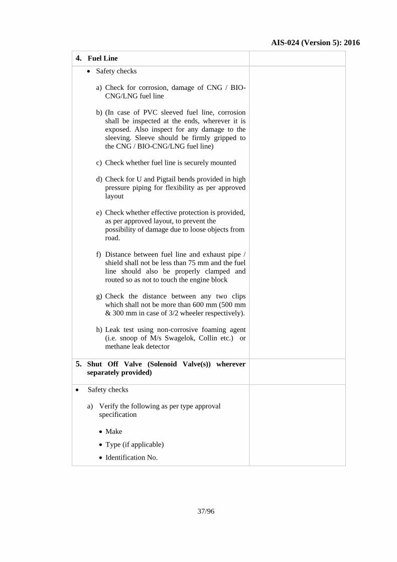
4. Fuel Line
Safety checks
a) Check for corrosion, damage of CNG / BIO-
CNG/LNG fuel line
b) (In case of PVC sleeved fuel line, corrosion
shall be inspected at the ends, wherever it is
exposed. Also inspect for any damage to the
sleeving. Sleeve should be firmly gripped to
the CNG / BIO-CNG/LNG fuel line)
c) Check whether fuel line is securely mounted
d) Check for U and Pigtail bends provided in high
pressure piping for flexibility as per approved
layout
e) Check whether effective protection is provided,
as per approved layout, to prevent the
possibility of damage due to loose objects from
road.
f) Distance between fuel line and exhaust pipe /
shield shall not be less than 75 mm and the fuel
line should also be properly clamped and
routed so as not to touch the engine block
g) Check the distance between any two clips
which shall not be more than 600 mm (500 mm
& 300 mm in case of 3/2 wheeler respectively).
h) Leak test using non-corrosive foaming agent
(i.e. snoop of M/s Swagelok, Collin etc.) or
methane leak detector
5. Shut Off Valve (Solenoid Valve(s)) wherever
separately provided)
Safety checks
a) Verify the following as per type approval
specification
Make
Type (if applicable)
Identification No.
Page 42
AIS-024 (Version 5): 2016
38/96
b) Check whether shut off valve is securely
mounted
c) Check operation for “Close & Open” as required
d) Leak test using non-corrosive foaming agent (i.e.
snoop of M/s Swagelok, Collin etc.) or methane
leak detector
6. Regulator
Safety checks
a) Verify the following as per type approval
specification
Make
Type(if applicable)
Identification No
b) Check whether regulator is securely mounted
c) Leak test using non-corrosive foaming agent
(i.e. snoop of M/s Swagelok, Collin etc.) or
methane leak detector
7. Heat exchanger Vaporizer(LNG)
Safety checks
a. Verify the following as per type approval
specification
Make
Type (if applicable)
Identification No.
b. Check whether regulator is securely
mounted
c. Leak test using non-corrosive foaming
agent(i.e. snoop of M/s Swagelok, collin
etc.) or methane leak detector
8. Gas-Air Mixer
Page 43
AIS-024 (Version 5): 2016
39/96
Safety checks
a) Verify the following as per type approval
specification
Make
Type(if applicable)
Identification No
b) Check whether gas-air mixer is securely
mounted
c) Leak test using non-corrosive foaming agent
(i.e. snoop of M/s Swagelok, Collin etc.) or
methane leak detector
9. Electrical wiring: Safety checks
9.1 For OE & Converted / Retrofitted In-Use
Vehicles
a) Check whether that current limiting device
(fuse) is fitted as per manufacturer
specifications and make
b) Terminals are insulated to prevent shorting
c) Wiring are taped and clipped with loom &
mounted securely
d) Battery shall be securely mounted and battery
terminal shall be locked properly by means of
suitable nut & bolt with washers.
e) Check installation of battery cut-off switch as
per vehicle / chassis manufacturer’s
recommendations (if applicable). Location of
Battery cut-off switch should be within the
reach of driver in seating posture in driving
seat.
f) Check routing of high tension cable to avoid
accidental earthing and to be placed away from
any heat source – as per Vehicle / chassis
manufacturer’s recommendations / layout or as
approved by Test Agency.
g) Check for proper make of high tension cable
connected to Spark Plug as per Vehicle/chassis
manufacturer’s recommendation. Check for tight
fitment of its terminal to the spark-plug
Page 44
AIS-024 (Version 5): 2016
40/96
9.2 FOR OE VEHICLES
a) Check wiring harness layout under the floor and in
the engine compartment to be in accordance with
Vehicle/chassis manufacturer’s layout /
specifications / approval
b) Check wiring harness in cabin and passenger
compartment to be as per vehicle/chassis
manufacturer’s guidelines / approval
c) Cable harness has to be as per the
recommendations of OE chassis / vehicle
manufacturers
9.3 FOR CONVERTED / RETROFITTED IN-USE
VEHICLES
a) Check wiring harness layout under the floor /
cabin and passenger compartment for proper
sleeving and routing in order to avoid accidental
sparking.
10. Service shut-off valve:
Safety checks –
a) Make & type
b) Check operation
c) Check whether service shut off valve is
securely mounted
d) Leak test using non-corrosive foaming agent
(i.e. snoop of M/s Swagelok, Collin etc.) or
methane leak detector
11. CNG / BIO-CNG/LNG Filter: (wherever
separately provided)
a) Check whether CNG / BIO-CNG/LNG filter is
securely mounted
b) Leak test using non-corrosive foaming agent (i.e.
snoop of M/s Swagelok, Collin etc.) or methane
leak detector
12. CNG / BIO-CNG Pressure Gauge
Content gauge in case of LNG :
a) Make & type
Page 45
AIS-024 (Version 5): 2016
41/96
b) Check whether CNG / BIO-CNG/pressure
indicator is securely mounted. Check whether
LNG Content gauge is securely mounted
c) Leak test using non-corrosive foaming agent (i.e.
snoop of M/s Swagelok, Collin etc.) or methane
leak detector
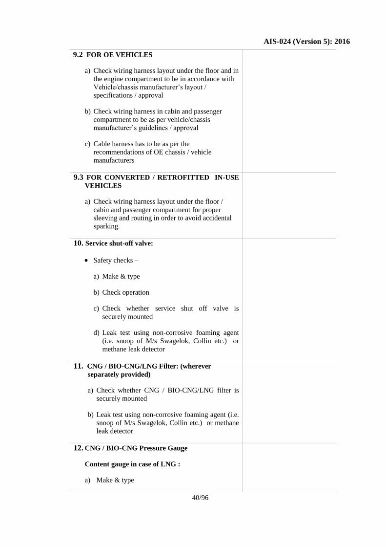
13. Compliance Plate:
Installation Check
Check for following
Details for no. of Cylinders
1 2 3 4 …
…
…
…
a) Cylinder identification No.
b) Date of last testing and the name of
certifying agency
c) Water capacity (ltr)
d) Next due date of testing
e) Water capacity (ltr) of total
installation
f) Vehicle registration/ identification No.
(to be furnished after registration)
g) Seal /Identification of the checking
/inspection agency(who carries out the
3rd
party inspection)
h) Check whether compliance plate is
installed near filling connection & be
clearly visible to the filling agency
14. Identification label in front and rear:
a) Located on left side of the front and rear
safety glass and shall ensure visibility from
front and rear sides
15. Compartment/Sub-compartment/Gas tight
housing(for internally mounted cylinder/s)
a) Check whether Compartment/Sub-
compartment/Gas tight housing is in
Page 46
AIS-024 (Version 5): 2016
42/96
good condition i.e. shall not show any
crack/damage.
b) Check whether it is firmly clamped to the
conduit/vent hose/ducting
16. Conduits/ducting/vent hose(for internally
mounted cylinder/s)
a) Check whether Conduits/ducting is in
good condition i.e. shall not show any
crack/damage
17. Petrol Shut Off Valve (Solenoid) (if
applicable i.e. Gasoline injection vehicle
PESOs not require such solenoid valve)
a) Check operation
b) Check whether Petrol shut off valve is
securely mounted
c) Leak test (visual inspection)
d) Verify the make & type as per the Type
Approval specification.
18. Fuel selection switch(for bi-fuel mode)
Check operation
19. Catalytic Converter(wherever it is part of kit)
a) Verify make and type of the catalytic
converter as per the vehicle
manufacturer’s specification and / as
given in the type approval certificate as
the case may be.
20. Low pressure hose
a) Verify make and type of the low pressure
hose as per the Type Approval
specification.
b) Check for kinks, damage or abrasion to
the cover
(Note: In case of doubt, Inspecting Agencies
will request the OE vehicle manufacturer/
retrofitter to supply the sample of material
Page 47
AIS-024 (Version 5): 2016
43/96
for low pressure hose which has been type
approved by the testing agencies.)
21. Following additional points are to be complied at the time of registration/
before endorsement by the competent authority (after conversion) of CNG /
BIO-CNG/LNG vehicle for enhancement of safety of vehicle.
a) Fire retardant material conforming to FMVSS 302 for seat/upholstery/roof
& side lining & IS:2465 for wiring cables shall be used. The OE / Vehicle
manufacturer/retrofitter shall submit declaration with respect to design,
manufacturing processes and material conforming the use of fire retardant
materials.
(Notes:
For OE fully built vehicles, type approval is subjected to meeting the
requirements as mentioned above. In case of type approval of drive-away
chassis, declaration from chassis manufacturer for above tests shall be
verified by inspection agency.
In case of doubt, Inspecting Agencies will request the OE vehicle
manufacturer/retrofitter to supply the sample of material for cables/ Seat/
upholstery/ roof & side lining which has been type approved by the testing
agencies.
b) (i) One number each of dry chemical powder type / CO2 type fire
extinguisher (1kg), for 4 wheeler (LCV etc.) only, shall be provided
in driver’s and passenger’s compartment.
(ii) One number of dry chemical powder type / CO2 type fire
extinguisher of 1 kg. shall be provided in L7, 3 wheeled and M1
category of vehicles such that it shall be easily accessible to all the
occupants.
c) For servicing of CNG / BIO-CNG/LNG vehicle proper instructions,
detailed operational & service manual with Dos & DON'Ts shall be
provided by kit/vehicle manufacturers. Vehicle / kit manufacturer/ kit
supplier should devise training module and impart training to drivers
and technicians for safe operation of CNG / BIO-CNG/LNG system.
d) Check for First-Aid kit as per CMVR.
e) Safety plates / shield below the pipe joints shall be welded and proper
inspection windows shall be provided near the cylinder joints.
f) Minimum one copy of safety instructions shall be displayed in
passenger’s compartment.
g) Check the following for the vehicles other than M1 category; fitted
with multi CNG / BIO-CNG/LNG cylinders not incorporating the
Page 48
AIS-024 (Version 5): 2016
44/96
independent venting system.
Check for proper venting provided by louvers / holes / mesh on the
side skirt so that in case of any leakage the entrapped gas under the
floor escapes to the atmosphere
The Vehicle/kit manufacturer/kit supplier to provide at least two
(total minimum area of 450 sq. mm) vent pipes connecting the
under floor of the vehicle to the rooftop for CNG / BIO-CNG/LNG
gas to vent out in case of leakage. The vent pipes to be located close
to the cylinder valves cluster as per recommendations of chassis
manufacturer. Construction should be such that leakage into
passenger compartment is avoided
h) Any other safety recommendations provided or advised by the
Vehicle/kit manufacturer/kit supplier to be complied with.
Note: The instructions issued by OE manufacturer/retrofitter for third party
evaluation, in their instruction manual, shall contain all the necessary
details on the methodology & the procedure for carrying out these checks.
Signature & Seal with date
Page 49
AIS-024 (Version 5): 2016
45/96
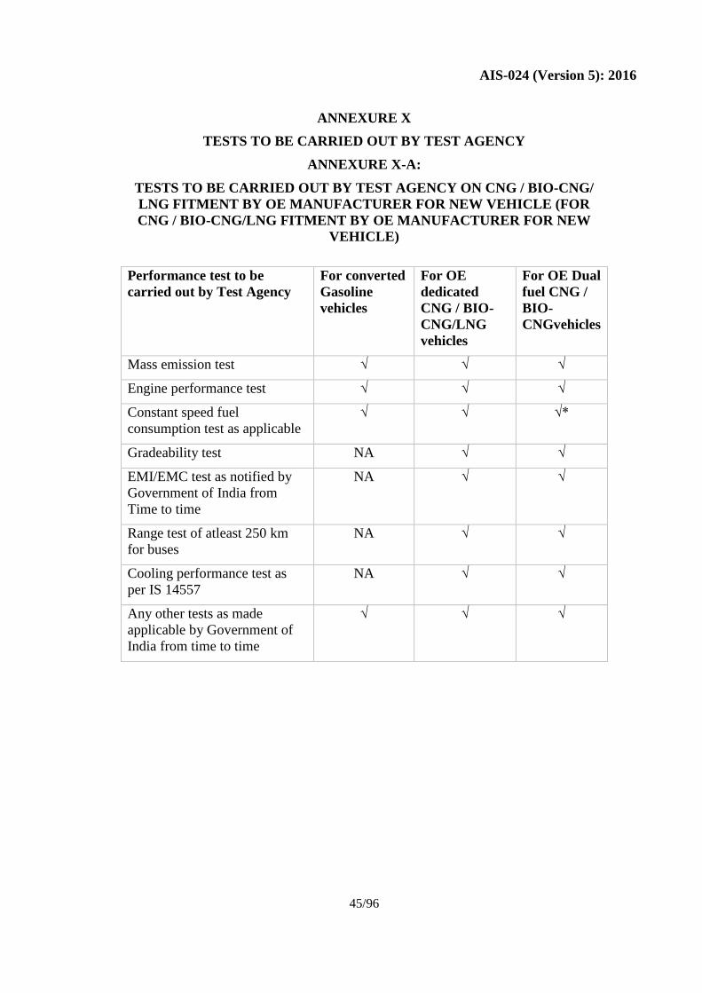
ANNEXURE X
TESTS TO BE CARRIED OUT BY TEST AGENCY
ANNEXURE X-A:
TESTS TO BE CARRIED OUT BY TEST AGENCY ON CNG / BIO-CNG/
LNG FITMENT BY OE MANUFACTURER FOR NEW VEHICLE (FOR
CNG / BIO-CNG/LNG FITMENT BY OE MANUFACTURER FOR NEW
VEHICLE)
Performance test to be
carried out by Test Agency
For converted
Gasoline
vehicles
For OE
dedicated
CNG / BIO-
CNG/LNG
vehicles
For OE Dual
fuel CNG /
BIO-
CNGvehicles
Mass emission test √ √ √
Engine performance test √ √ √
Constant speed fuel
consumption test as applicable
√ √ √*
Gradeability test NA √ √
EMI/EMC test as notified by
Government of India from
Time to time
NA √ √
Range test of atleast 250 km
for buses
NA √ √
Cooling performance test as
per IS 14557
NA √ √
Any other tests as made
applicable by Government of
India from time to time
√ √ √
Page 50
AIS-024 (Version 5): 2016
46/96
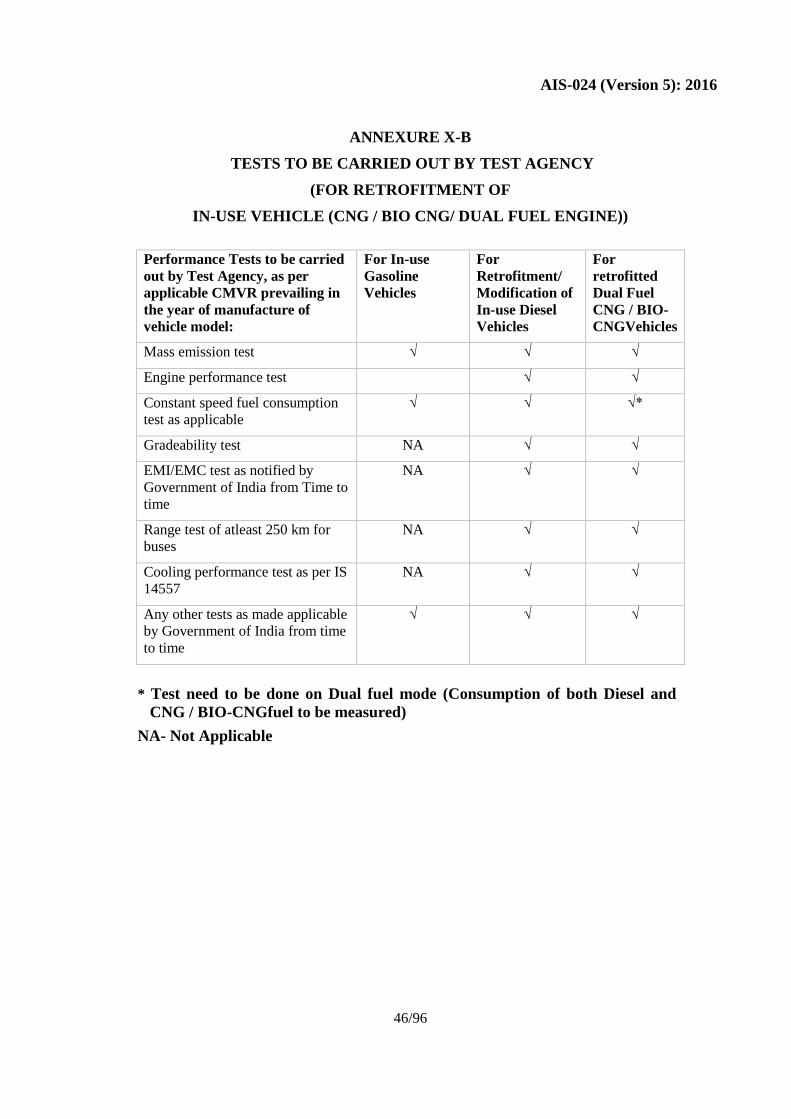
ANNEXURE X-B
TESTS TO BE CARRIED OUT BY TEST AGENCY
(FOR RETROFITMENT OF
IN-USE VEHICLE (CNG / BIO CNG/ DUAL FUEL ENGINE))
Performance Tests to be carried
out by Test Agency, as per
applicable CMVR prevailing in
the year of manufacture of
vehicle model:
For In-use
Gasoline
Vehicles
For
Retrofitment/
Modification of
In-use Diesel
Vehicles
For
retrofitted
Dual Fuel
CNG / BIO-
CNGVehicles
Mass emission test √ √ √
Engine performance test √ √
Constant speed fuel consumption
test as applicable
√ √ √*
Gradeability test NA √ √
EMI/EMC test as notified by
Government of India from Time to
time
NA √ √
Range test of atleast 250 km for
buses
NA √ √
Cooling performance test as per IS
14557
NA √ √
Any other tests as made applicable
by Government of India from time
to time
√ √ √
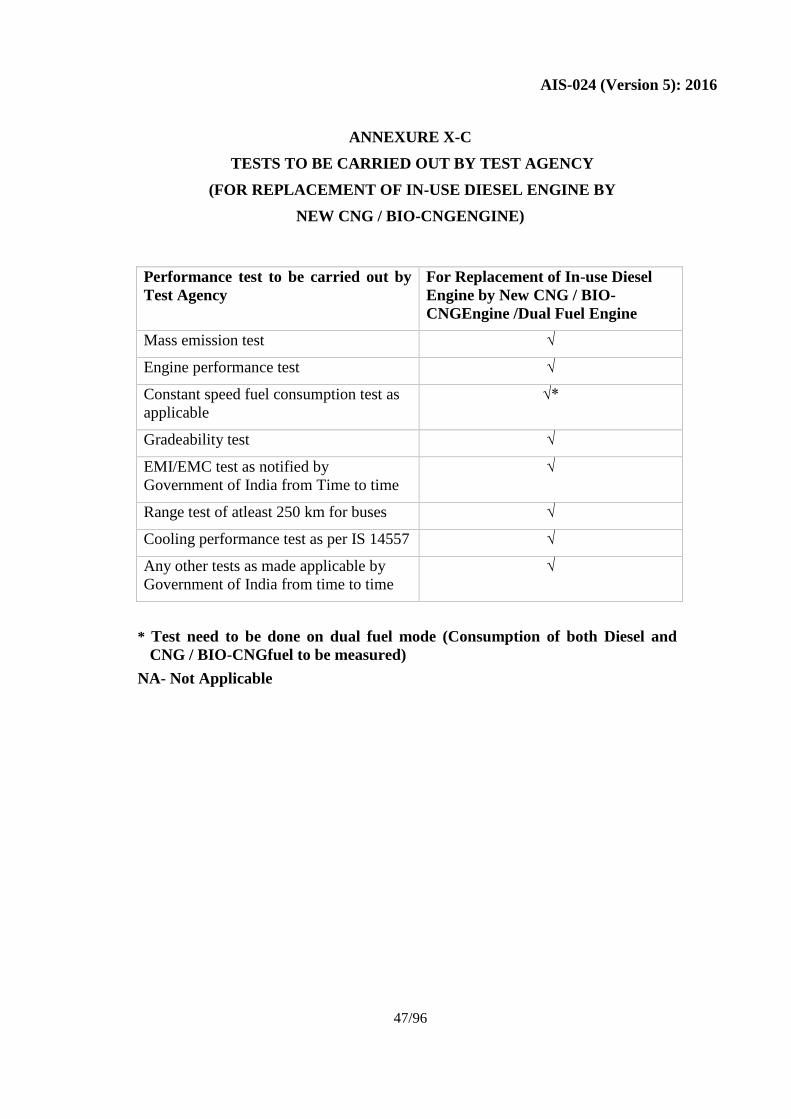
* Test need to be done on Dual fuel mode (Consumption of both Diesel and
CNG / BIO-CNGfuel to be measured)
NA- Not Applicable
Page 51
AIS-024 (Version 5): 2016
47/96
ANNEXURE X-C
TESTS TO BE CARRIED OUT BY TEST AGENCY
(FOR REPLACEMENT OF IN-USE DIESEL ENGINE BY
NEW CNG / BIO-CNGENGINE)
Performance test to be carried out by
Test Agency
For Replacement of In-use Diesel
Engine by New CNG / BIO-
CNGEngine /Dual Fuel Engine
Mass emission test √
Engine performance test √
Constant speed fuel consumption test as
applicable
√*
Gradeability test √
EMI/EMC test as notified by
Government of India from Time to time
√
Range test of atleast 250 km for buses √
Cooling performance test as per IS 14557 √
Any other tests as made applicable by
Government of India from time to time
√
* Test need to be done on dual fuel mode (Consumption of both Diesel and
CNG / BIO-CNGfuel to be measured)
NA- Not Applicable
Page 52
AIS-028 (Version 5): 2016
48/96
CODE OF PRACTICE FOR USE OF CNG / BIO-CNG/LNG FUEL
(DEDICATED/ BI-FUEL/DUAL FUEL) IN INTERNAL COMBUSTION
ENGINED VEHICLES
1.0 GENERAL
This code of practice may be called as "Code of Practice for Use of CNG /
BIO-CNG/LNG fuel in Internal Combustion Engined Vehicles ". It may be
noted that Liquefied Natural Gas (LNG) shall be permitted for OE
manufactured dedicated LNG Vehicles having GVW ≥ 3.5 T .
This code of practice is applicable to vehicle categories as per AIS- 053.
1.1 SCOPE
1.1.1 This code of practice shall apply to the design, construction, installation,
operation, maintenance, inspection, testing and fueling of compressed
natural gas (CNG / BIO CNG) systems where CNG / BIO-CNG/LNG* is
used either Dedicated/Dual fuel/bi-fuel for internal combustion engines.
In general the Standard is directed towards vehicle installations. *It may
be noted that Liquefied Natural Gas (LNG) shall be permitted for OE
manufactured dedicated LNG Vehicles having GVW ≥ 3.5 T .
1.1.2
It is not intended to cover the areas where major structural modifications are
to be carried out to the vehicle (major structural modifications are those not
defined in 1.1.4). Prior to commencement of such work guidance should be
sought from the vehicle manufacturer.
1.1.3
Special circumstances exist for construction equipment vehicles with internal
combustion engines. Accordingly a separate section is included to cover the
special requirements of the construction equipment vehicles.
1.1.4
Any alterations or modification to any vehicle to install equipment shall be
carried out in accordance with sound engineering practices and in compliance
with Central Motor Vehicles Act 1988 and Central Motor Vehicles Rule, 1989
and their superseding amendment and notification issued thereafter. The
following aspects shall be taken into consideration during alteration or
modification:
Where modifications are made to:
(a) Suspension: mounting locations, geometry, ground clearance adjustment,
axles and sub-axles, or steering mechanism
(b) Original fuel storage: the fuel tank assembly, fuel tank mounting, venting
or filler assemblies.
NOTE – In some instances the fuel tank constitutes a structural member of
the vehicle.
(c) Vehicle structure: Holes greater than 13 mm shall not be located within 40
mm of the edge of a panel, welded joint or direct load bearing point (such
as a belt anchor). The only holes permitted greater than 13 mm diameter
Page 53
AIS-028 (Version 5): 2016
49/96
are of the installation of the filling valve or for venting purposes.
(d) Braking system including the hand brake and components.
In this aspect, design guidelines supplied by vehicle manufacturers, vehicle
safety standards of Indian or relevant standard, wherever applicable shall be
referred.
NOTE- In case of the retrofitment, where modification types (a) (b) (c) and
(d) are carried out to heavy motor vehicles these will require prior
design approval from vehicle manufacturer.
1.2 Approved equipment
Only equipment and systems approved by the relevant Statutory Authority /
Test Agency shall be used.
1.2.1 This Standard is not intended to cover CNG / BIO-CNG/LNG fuel systems
for the propulsion of marine craft.
1.3
Definitions
For the purpose of this Standard, the following definitions shall apply:
Approved or approval. Approved by or approval of the Statutory Authority.
Authorized person. A person, normally an automotive workshop person,
authorised by the vehicle manufacturer or the conversion kit manufacturer/kit
supplier specially trained for installation, maintenance and periodic inspection
of motor vehicle converted for Dual fuel or bi-fuel or dedicated operation of
internal combustion engined vehicles.
Automatic fuel shut-off valve. A device such as solenoid valve for shutting
off the fuel supply unless certain essential conditions exist.
Compressed natural gas (CNG / BIO CNG). A compressed gaseous fuel
composed predominantly of Methane (CH4), shall be used as specified by the
Government of India from time to time.
Bio-CNG (biomethane) shall meet the requirements of IS 16087 -2016 and
shall be stored and transported through cylinders conforming to IS 7285(Part
2) and f or automotive use, it shall be filled in cylinders conforming to IS
15490.
Liquefied Natural Gas (LNG): Natural gas that has been cooled to -259
degrees Fahrenheit (-161 degrees Celsius) and at which point it is condensed
into a liquid which is colorless, odorless, non-corrosive and non-toxic.
Characterized as a cryogenic liquid. Fuel quality for Automotive use shall
meet the requirements of BIS specification as notified from time to time by
MoPNG , Govt of India.
Construction equipment vehicles. Means rubber tyred, including pneumatic
tyre rubber padded or steel drum wheel mounted, self propelled, excavator,
loader, back compactor roller, dumper, motor grader, mobile crane, dozer,
fork lift truck, self loading concrete mixer or any other construction
equipment vehicle or combination then designed for off-highway operations
in mining, industrial undertaking, irrigation and general construction but
Page 54
AIS-028 (Version 5): 2016
50/96
modified and manufactured with “on or off” or “on and off” highway
capabilities.
Cylinder. A pressure vessel for storage of CNG / BIO-CNG/LNG for use as
fuel for an internal combustion engine, approved / endorsed by Department of
Explosives under Gas Cylinder Rules, 1981 as amended from time to time.
LNG cylinder shall meet the requirements of Gas Cylinder Rules 2016 or
equivalent standard or as approved / endorsed by PESO under Gas Cylinder
Rules, 2016 as amended from time to time.
Cylinder valve. A manually controlled shut-off valve fitted on the cylinder
which can open or shut off the CNG / BIO-CNG / LNG supply and which
incorporates a burst disc (NA for LNG) backed with a fusible material,
approved / endorsed by Department of Explosives under Gas Cylinder Rules,
as amended from time to time.
LNG cylinder valve(s) shall meet the requirements of Gas Cylinder Rules
2016 or as approved / endorsed by Department of Explosives under Gas
Cylinder Rules 2016 as amended from time to time.
Dedicated engine (for diesel engine conversion only). An engine operating
on gaseous fuel only.
Downstream. Is the direction in which the stream flows.
Excess-flow valve. A valve normally in the open position which closes
automatically in the direction of flow for which it is designed, when a
predetermined flow limit is exceeded.
Excess pressure device/ Pressure relief valve. An automatic pressure
relieving device.
Gas-air mixer. A device for introducing gaseous fuel to the induction air of
the engine.
Heavy motor vehicle. A vehicle for either goods or passenger services as
defined under the Central Motor Vehicle Rules (CMVR) as applicable.
Non-return valve/ Check valve. A valve, which permits fuel flow in one
direction only.
Pressure. Pressure refers to gauge pressure.
Pressure indicator. A device to indicate the pressure of gas in the cylinder.
Regulator. A device which reduces fuel pressure to a level appropriate for
the delivery to the gas-air mixer.
Service fuel line. The fuel line running from the storage cylinder and
terminating at the regulator.
Service shut-off valve. A manually operated shut-off valve fitted on the
cylinder, which can open or shut off the CNG / BIO-CNG / LNG supply for
maintenance, servicing or emergency requirements.
Page 55
AIS-028 (Version 5): 2016
51/96
Shall. The word “shall” is used to indicate a requirement that must be
adopted to comply with this Standard.
Should. The word “should” is used to indicate a recommended practice.
Shut-off valve A valve for stopping gas flow.
Statutory authority. The Government Department or agency responsible for
the particular aspect (See Appendix B).
Upstream. Is the direction against the flow of the stream.
1.4 Special requirements
The fitment of a CNG / BIO-CNG/LNG fuel system shall be prohibited in any
vehicle with a passenger compartment heating system, which draws air from
the engine compartment unless the heating system is made inoperable and
gas-tight to the passenger compartment.
2.0 CYLINDER
2.1 Design approval
2.1.1 Cylinders shall be approved / endorsed by the PESO as per Gas Cylinder
Rules, 2016 as amended from time to time.
2.1.2
The weight of the CNG / BIO-CNG/LNG cylinder(s) will affect the unladen
weight of the vehicle and therefore consideration of the effect on the legal and
manufacturer’s rating and axle loadings should be considered.
2.1.3 In no circumstances shall the vehicle’s critical load distribution affecting
safety considerations be compromised.
2.1.4 Cylinders shall be re-tested as per Gas Cylinder Rules, 2016, as amended
from time to time.
2.2 Fittings on cylinders and filling connection
2.2.1 Cylinder valve
Each cylinder shall have a manual cylinder shut off valve mounted directly on
it capable of shutting off all gas flow from that cylinder. Cylinders and shut-
off valve assemblies shall be approved / endorsed by the PESO, as per Gas
Cylinder Rules, 2016, as amended from time to time.
2.2.1.1 following Accessories fitted to the LNG tanks as approved / endorsed
by PESO
2.2.1.1.1 Automatic valve
An automatic valve shall be installed in the fuel supply line, either directly on
every LNG tank (in a protected position) or as close as practicable after the
vaporizer in the LNG system.
The automatic valve shall be operated such that the fuel supply is cut off
when the engine is switched off, irrespective of the position of the ignition
switch, and shall remain closed while the engine is not running.
Page 56
AIS-028 (Version 5): 2016
52/96
A delay of 2 seconds is permitted for diagnostic.
2.2.1.1.2. Excess flow valve
The excess flow valve can be fitted inside or directly on the LNG tank (in a
protected position).
2.2.1.1.3. Pressure relief valve (primary)
The primary pressure relief valve outlet shall be connected to an open ended
pipe-away system to move vented gas away to a high level. Consideration
shall be given to preventing any blockage or freezing of the pipe-away. The
LNG primary relief valve shall not vent into the gas tight housing (if fitted).
2.2.1.1.4. Pressure relief valve (secondary)
The secondary relief valve may relieve gas immediately from its outlet.
Protection from water ingress and damage shall be considered. The secondary
relief valve outlet shall not be connected to the same pipe-away as the primary
relief valve. The LNG secondary relief valve shall not vent into the gas tight
housing (if fitted).
2.2.1.1.5. Manual fuel shut off valve
The manual fuel shut off valve shall be mounted directly on the LNG tank (in
a protected position). It should be readily accessible. The manual fuel shut off
valve can be integrated into the automatic valve.
2.2.1.1.6. Manual vapour shut off valve
The manual vapour shut off valve shall be mounted directly on the LNG tank
(in a protected position). It should be readily accessible.
2.2.1.1.7. Vent line or connector
The vent line or connector may be mounted inside or on the LNG tank (in a
protected position). It should be readily accessible. The vent connector shall
be suitable for the purpose at temperatures indicated in Annex 5O of ECE
R110 for the working pressure of the LNG tank.
2.2.1.1.8. Venting management system
The primary pressure relief valve shall be piped to a vent stack which extends
to a high level. The primary and secondary relief valve outlets shall be
protected from fouling by dirt, debris, snow, ice and/or water. The vent stack
shall be sized to prevent flow restriction due to pressure drop. Gas exiting the
vent stack or secondary relieve valve shall not impinge on enclosed areas,
other vehicles, exterior-mounted systems with air intake (i.e. air-conditioning
systems), engine intakes, or engine exhaust. In the case of dual tanks, the
primary relief valve outlets piping for each tank may be manifold to a
common stack.
2.2.2 Filling Connection
The filling connection shall be of the NZS/NGV-1 or any other type as
specified by the Government of India from time to time for CNG /Bio CNG
vehicles. For heavy duty vehicles it is mandatory to use Automatic CNG/Bio
CNG Cylinder Valve with Pressure Relief Device (PRD) as approved /
Page 57
AIS-028 (Version 5): 2016
53/96
endorsed by PESO under Gas Cylinder Rules, 2016 as amended from time to
time.
The basic dimensions for NZS type are as given in Appendix D and
recommended sizes of NGV – 1 type of filling connection are SAE 9/16” and
7/8”. However, the vehicle manufacturer / kit installer may seek the guidance
from The Gas Authority of India Ltd. / Ministry of Petroleum and Natural Gas
about the use of specific type of NGV – 1 nozzle.
In case of LNG, the refilling receptacle shall be as per ECE R 110 or
equivalent standerd, The LNG filling receptacle shall be made out of non-
sparking material and should comply with the no igniting evaluation tests
described in ISO 14469 1:2004 or equivalent standerd. However, the vehicle
manufacturer / kit installer may seek the guidance from PESO / Ministry of
Petroleum and Natural Gas about the use of specific type of LNG receptacle.
When the CNG/LNG container or tank is installed in the passenger
compartment or an enclosed (luggage) compartment the filling unit shall be
located at the outside of the vehicle.
2.2.3 The NZS type filling connection shall be provided with a captive dust plug
and NGV-1 type filling connection shall be provided with dust protection cap.
2.2.4 Position of filling connection
The filling connection shall be located in suitably protected and ventilated
location, usually the engine compartment Incase of LNG both tank mounted
and remote mounted options of LNG receptacles will be allowed. Remote
mounted receptacle will be permitted in case of multi tank vehicle
configuration and buses where tanks are mounted inside the body structure. It
shall comply with the following:
(a) The filling connection is made and filling is supervised from outside the
vehicle. The filling connection may be made only if the method of access
to it from outside PESOs not results in the opening of a vapour path to the
interior of the vehicle, thereby negating the effectiveness of a
compartment or sub-compartment.
(b) The filling connection is protected by being located in a recess below the
surface of a body panel, or by being located so that equivalent protection
is provided by the construction of the vehicle.
(c) The filling connection shall be attached to motor vehicle in such a
manner as to resist, without permanent deformation of the mounting
attachment, a proof load of 50 kgf applied in the forward and reverse
directions of travel of the vehicle.
The proof load shall be applied by full engagement of the filling
connection and shall be representative of attempted movement of the
vehicle while refueling.
(e) The filling operation can be carried out without requiring the operator to
lie or crawl under the vehicle or be otherwise subjected to inconvenience,
discomfort or hazard.
Page 58
AIS-028 (Version 5): 2016
54/96
2.2.5 Refueling Interlock Device (Not applicable to LNG vehicle)
Filling connections in motor vehicles shall be fitted with a system that
prevents the engine starting when the dust plug or dust protection cap is
removed. This system shall isolate the starting device of the vehicle. Any
other system that isolates the engine starting shall be considered.
2.2.6 Non-return valve/ Check valve
There shall be a non-return valve fitted on the refueling line to prevent the
return flow of gas from the cylinder to the filling connection. The non-return
valve shall be located as close to the filling connection as it is practicable.
In case LNG, the check valve shall meet the requirements of ECE R110 or
equivalent standard.
2.2.7 Excess flow valve
A device may be fitted in the fuel line preferably at the outlet of the cylinder
valve which prevents the total contents of the cylinder from discharging to
atmosphere in the event of rupture to any part of the fuel line or components.
In case LNG, the excess flow valve valve shall meet the requirements of ECE
R110 or equivalent standard.
2.2.8 Diesel Fuel cut off
A device/mechanism to be provided in the Dual fuel system for cutting of the
diesel supply while filling CNG / BIO-CNG fuel in the vehicle.
2.3
Location, Ventilation and Mounting of Cylinders
2.3.1 Cylinders, Fittings and Pipe work.
2.3.1.1
Cylinder shall be mounted in a protected location inside the perimeter of the
vehicle. Cylinders shall not be located so that the vehicle driving
characteristics are adversely affected.
Provisions on components fitted to the LNG tank approved by PESO
The LNG tank shall be equipped at least with the following components,
which may be either separate or combined (special care shall be taken to
prevent LNG trapping):
Pressure relief valve;
Manual valve;
Automatic valve;
Excess flow device.
The tank may be equipped with a gas-tight housing, if necessary.
Leakage and venting from LNG tanks
In the case of LNG tanks are located in enclosed spaces for extended
periods of time (e.g. for service), leakage and venting of natural gas (or
other flammable substances) from the tank shall be dealt with properly to
avoid the dangers due to releasing flammable substances in enclosed
spaces.
Page 59
AIS-028 (Version 5): 2016
55/96
Vehicle LNG tank(s) shall have a design hold time (build without
relieving) minimum of 5 days after being filled net full and at the highest
point in the design filling temperature/pressure range. Manufacturer to
provide self declaration.
LNG Tank supports
The manufacturer shall specify the means by which the tank(s) shall be
supported for installation on vehicles. The manufacturer shall also supply
installation instructions, including maximum clamping force and torque to
not cause unacceptable stress in the tank or damage to the tank surface.
2.3.1.2
For externally mounted cylinders:
In no case shall cylinder valves be positioned less than 200 mm from the
extremities of the vehicle unless they are protected to minimize the possibility
of damage due to collision, overturning or other accident.
Where the operation of the vehicle is such, that the cylinder will be subjected
to impact damage from loose metal or other objects being thrown up from the
road, effective shielding against these shall be provided.
2.3.1.3
The cylinder shall be situated and vented so that any gas escaping due to
leakage from the cylinder valve shall not enter the vehicle passenger
compartment or driver space.
2.3.1.4 The clearance between the cylinder the exhaust shall not be less than 75 mm.
2.3.1.5 For Heavy Motor Vehicles Only
2.3.1.5.1
In the case of heavy motor vehicles, the number of cylinders likely to be
required will be of sufficient weight to affect the legal maximum vehicle
weight constraints. The effects of the chosen position of the cylinders on the
following criteria must be assessed, and if necessary, a reduction in the
allowable payload of the vehicle under study be considered.
(a) The original manufacturer’s maximum design axle loadings.
(b) The maximum allowable axle loadings.
(c) The maximum gross vehicle weight and/or gross combination weight
allowed by the original manufacturer.
A number of alternative cylinder mounting positions may have to be
considered in order to minimize the effects mentioned above. The effects of
removing or replacing existing diesel fuel tanks on weight distribution of the
vehicle should also be taken into account in the above calculations.
NOTE- Vulnerability of cylinders and fittings to damage during loading and
unloading of the vehicle or load shift or spillage shall be taken into
account.
2.3.2
(a) Cylinder shall not be fitted in any position behind the driver seat (seat
adjusted to rear most position), which will hinder the driver seat
adjustment unless specifically approved by the testing agency.
Page 60
AIS-028 (Version 5): 2016
56/96
(b) Cylinder shall not be fitted in a position beneath the vehicle that
decreases the effective ground clearance.
(c) In case of heavy vehicles (bus having more than 3.5 GVW), for fitment
of cylinders on roof, the strength of roof shall be validated by testing
agency based on design calculation provided by vehicle manufacturer /
kit manufacturer / kit supplier.
(Refer to Fig. 1 for 4-wheeler below 3.5 tonnes GVW)
2.3.3 Vehicle mounted cylinders
2.3.3.1 A cylinder installed in a vehicle shall be permanently mounted and filled in
that position.
2.3.3.2
Cylinder location ground clearance
Cylinders shall be located in accordance with all the following requirements:
(a) The vehicle mass for determining ground clearance shall be the laden
mass, including permanent non-standard attachments to the vehicle with
all fuel, water and oil containers full.
(b) Cylinders installed between and behind axles shall not be lower than the
lowest of the following points and surfaces forward of the cylinder (refer
figure 1 for 4-wheeler below 3.5 tonnes and figure 2 for 4-wheeler and
above exceeding 3.5 tonnes GVW):
(i) The lowest structural component of the body
(ii) The lowest structural component of the frame or sub-frame, if any
(iii) The lowest point of the engine
(iv) The lowest point on the transmission (including the clutch housing
or torque converter housing as applicable) but excluding differential
housings.
(v) The original fuel tank or tanks and or brackets
(vi) Approach and departure clearances shall be below planes defined in
figure 2 (for 4-wheeler and above exceeding 3.5 tonnes GVW).
NOTE- Suspension spring U bolts are not classified as structural
components.
(vii) In any case the lowest point of the cylinders shall not be lower than a
horizontal line taken at the lowest point of the front and rear wheel
rims (line AB in Figure 2) (for 4-wheeler and above exceeding
3.5 tonnes GVW).
(c) Ramp angle (for 4-wheeler below 3.5 tonnes GVW): The cylinder(s) shall
not be lower than a point defined by a ramp angle of 17 deg. (Refer
Appendix F for calculation).
To calculate ramp angle the following measurements shall be taken (refer
Fig. 1):
(i) A plane through the centre line point of road contact of the front
Page 61
AIS-028 (Version 5): 2016
57/96
wheel (B), sloping upward to contact the lowest structural point of the
vehicle midway between the axles (A) (line AB in Fig 1); and
(ii) A plane sloping from point (A) defined in (i) downward to the centre
line point of road contact of the foremost rear axle wheel (C) (line AC
in Fig. 1).
(d) Departure angle (for 4-wheeler below 3.5 tonnes GVW)
(i) The cylinders shall lie within an area C-D in fig. 1.
(ii) When calculating departure angle the measurement shall be taken
along angular plane tangential to the centre line point of road contact
of the rear most axle wheel sloping upward and outward to the
extremity of the permanent body work or original equipment bumper
bar whichever is the lower.
(e) All clearances shall be measured to the bottom of the cylinder or to the
lowest fitting, support or attachment on the cylinder or cylinder housing,
whichever is lowest.
2.3.4 Internal cylinders
Where a cylinder is located within the body shell of a vehicle, either:
(a) The whole body of the cylinder together with its attached components and
fittings shall be enclosed in a compartment; or
(b) The valves and pipe connections associated with or attached to the
cylinder shall be enclosed in a localized sub-compartment, which is
attached to the cylinder and vented to the atmosphere.
Provision shall be made for ready access to the cylinder valve in all
installation arrangements.
NOTE - The luggage boot of a car is not considered to be acceptable as a
cylinder compartment under (a) above, because of difficulties
concerning effectiveness of sealing, the maintenance of ventilation
openings, and the presence of electrical equipment in most boots.
2.4 Construction of compartments and sub-compartments
2.4.1
A cylinder compartment or sub-compartment shall comply with the following
requirements:
(a) Construction shall be such that any gas which might leak from any
fittings, component or piping, can not pass to any other enclosed
compartment, passenger space or luggage space of the vehicle
(b) When a sub-compartment has been subjected to hydrostatic internal
pressure of 30 kPa applied for 5 min, sealing materials or gaskets shall
not be displaced or otherwise lose integrity during the test.
(c) Hatches, covers, or construction joints, which may need to be opened or
dismantled during maintenance or inspection, shall be capable of being
opened at least 10 times without adverse effects on durability. Hinges and
Page 62
AIS-028 (Version 5): 2016
58/96
locking devices of hatches and covers shall be designed to prevent the
dislodgment of the hatch or cover when in the closed and locked position.
(d) The construction shall be such that when subjected to a pushing force of
60 kgf, applied at any point on any external face of the sub-compartment,
any resultant damage shall not be of a nature to permit gas leakage in the
event of pressure testing as in (b) above. The pushing force shall be
applied by a measuring instrument having a flat circular face of 20 mm
diameter.
(e) It shall be possible to operate the cylinder service shut-off valve in the
installed position. The valve may be arranged so that it can be operated
from some internal area of the vehicle provided that the sealing of the
compartment or sub-compartment shell is maintained by one of the
following means, as appropriate:
(i) If a valve actuating device passes through the shell a gas-tight seal
shall be provided.
(ii) If the actuating handle is wholly within the shell, access shall be a
gas-tight captive hatch. The design shall not need tools to open the
hatch.
(f) A compartment or sub-compartment shall not contain ignition sources or
electrical equipment or wiring unless it is intrinsically safe.
NOTE – Items (b), (c) and (d) are intended to be the basis of approval
for proof of design.
2.4.2
Ventilation
One or more vents to the outside of the vehicle shall be provided, the
aggregate area of which is not less than 550 mm2 for vehicles other than 2-
and 3-wheeler and 250 mm2
for 2- & 3-wheelers. The vents shall be so
located as to exhaust any gas, which may accumulate in the compartment or
sub-compartment to atmosphere and shall exit not less than 75 mm from an
exhaust pipe or other heat source. (Refer also to 2.4.3 (c)). Holes for venting
shall be positioned not less than 40 mm from the edge of a panel or a welded
joint or direct load bearing point (refer also to 1.1.4(c)).
2.4.3
Ducting
2.4.3.1
All piping or hoses that pass through an enclosed area of the vehicle shall be
within a conduit gas-tight from the vehicle interior, vented unobstructed to
outside atmosphere and protected from external damage and shall comply
with the following requirements:
(a) The ducting shall be as short as practicable.
(b) The connections shall be mechanically clamped and shall not depend on
adhesives or sealing compounds to retain them in place. Protection in the
form of a gasket shall be provided to prevent damage to the ducting
material by the clamping device.
(c) The material of the conduit used for ducting shall be sufficiently strong to
resist mechanical damage, preserve venting integrity, protect the piping or
hose within it, shall not support combustion and shall meet the following
minimum criteria:
Page 63
AIS-028 (Version 5): 2016
59/96
(i) The conduit shall withstand an internal pressure of 30 kPa.
(ii) The conduit shall not suffer sufficient damage to permit leakage when
tested by applying a 60 kgf static force applied through 20 mm
diameter, in the following manner.
(1) Applied to a free length of conduit (minimum length of 500 mm).
(2) With the conduit connection clamped up in position the force
then applied 5 mm from the end of this coupling so as to place
the connection in tension.
(iii) Flammability. The material shall conform to SAE J 369a class
SE/NBR.
(iv) Presence of resistance to ultraviolet degradation agent shall be
confirmed.
NOTE – Item (c) shall be the basis of approval for proof of design of the
conduit.
2.4.3.2
Pliable material
A sub-compartment may be constructed of pliable material attached to the
cylinder so that the cylinder valve, piping and connections are contained
within the sub-compartment. The pliable material shall meet the requirements
of this clause and shall be clearly marked accordingly.
2.4.3.3
Where the sub-compartment is removed to initiate repairs or at the periodic
inspection special attention shall be given to the inspection of the material to
ensure that no degradation of material has taken place. Any sub-compartment
showing signs of degradation shall be replaced.
2.4.3.4
The cylinder valve actuating device position shall be clearly identified and
shall have provided adequate material to allow closing of the valve without
damage to the sub-compartment sealing.
2.4.3.5
The pliable sub-compartment shall be shielded or installed in a protected
location to prevent damage, from unsecured objects and abrasion and:
(a) The material shall be sufficiently strong to resist mechanical damage,
preserve venting integrity, shall not support combustion and shall meet
the following minimum criteria:
(i) Resistance to cold cracking. The material shall withstand a bend of
180º applied within 0.5 seconds around a 6 mm diameter former at
temperature of –35ºC without cracking.
(ii) Flammability. The material shall conform to SAE J369a class
SE/NBR.
(iii) Presence of resistance to ultraviolet degradation agent shall be
confirmed.
NOTE – Item (a) shall be the basis of approval for proof of design.
Page 64
AIS-028 (Version 5): 2016
60/96
2.5
Cylinder(s) installation
For CNG Cylinders
(For Construction Equipment Vehicles refer clause (9))
2.5.1 Attachment to vehicle (refer also to 2.5.1(e))
Cylinders shall be securely attached to the vehicle to prevent slipping,
rotating and jarring loose, in accordance with the following requirements:
(a) The method of attachment shall not cause undue stresses or wear in the
cylinder shell;
(b) The mounting method shall not significantly weaken the vehicle
structure, and reinforcement shall be added where necessary to ensure
compliance with (c) below. An air gap of not less than 5 mm shall be
provided between the cylinder and vehicle structure;
(c) The force necessary to separate the cylinder from the vehicle shall not
be less than 20 times the mass of the full cylinder in any direction.
The strength of the anchorages may be established by static test (forces
directed through the centre of mass of the cylinder).
(d) In the absence of testing or where calculations are impracticable, the
following design requirements shall apply:
(i) There shall be at least 4 points of attachment to the vehicle
structure. The spacing between these shall be sufficient to ensure
the stability of the cylinder.
(ii) Where a cylinder is anchored to steel sheet metal the sheet metal
shall be reinforced by a plate of not less than 3600 mm2 and a
thickness of not less than 2.5 mm or appropriate thickness
supported by the calculation or test report. It is preferred that a
round washer be used but where a square plate is fitted the corners
shall be radiused. Any such reinforcement plate/washer shall be
contoured to the shape of the sheet metal or chassis rail.
Table 1
Cylinder size
(water capacity in ltrs.)
Over, up to and
including
L
Band dimensions –
Minimum nominal
size
(mm)
Bolt or stud diameter
for strap or flange
mountings minimum
nominal size
(mm)
0 -30 30 x 2 10
30-100 30x3 10
100 150 50 x 6 12
Above 150 Specific design
required
--
(iii) Where anchorage bolts pass through a hollow section, provision shall
be made to prevent collapse of that section under load.
(iv) Anchorage bolts or studs shall have a diameter not less than that shown
in Table 1 and shall conform to strength grade 8.8, IS: 1364 or
Page 65
AIS-028 (Version 5): 2016
61/96
equivalent ISO:4014 with nuts to IS:1364 or ISO:4032.
(v) Where clamping bands are used, at least two steel bands per cylinder
shall be provided, the dimensions, of which shall not be less than those
in Table 1.
To prevent possibility of external corrosion where clamping bands are
used a non-moisture retaining hard rubber or equivalent material shall
be provided on the inner side of the bands. Similar adequate
protection to the cylinder shall also be provided wherever the cylinder
rests against other metal objects such as the mounting frame.
(vi) Where the attachment is by means of clamping bands there shall be a
positive means of resisting end loads on the cylinder by means of
providing suitable end stoppers (Except for transverse mounted
cylinders).
(vii) Screwed fasteners or clamping devices shall either be inherently
resistant to loosening or be locked or pinned after tightening.
(e) The chassis of heavy motor vehicles can be subjected to considerable
torsional and bending deflections even under normal operating
conditions. Mounting of cylinders to chassis rails must take these
deflections into account and the cylinder mounting method chosen must
not unduly prevent these deflections occurring.
For LNG Cylinders
LNG Cylinder installation guidelines (ref Fig 5)
Mounting of LNG Tank :
The manufacturer shall specify the means by which the tank(s) shall be
supported for installation on vehicles. The manufacturer shall also supply
installation instructions, including maximum clamping force and torque to
not cause unacceptable stress in the tank or damage to the tank surface.
Installation instructions shall be provided to ensure that the cylinders will not
suffer unacceptable damage during installation and during normal operation
over the intended service life.
Where the mounting is specified by the manufacturer, the instructions shall
contain where relevant, details such as mounting design, the use of resilient
gasket materials, the correct tightening torques and avoidance of direct
exposure of the cylinder to an environment of chemical and mechanical
contacts.
a. Where the mounting is not specified by the manufacturer, the
manufacturer shall draw the Installer's attention to possible long term
impacts of the vehicle mounting system, for example: vehicle body
movements and cylinder expansion/contraction in the pressure and
temperature conditions of service.
b. The container and/or tank shall be permanently installed in the vehicle
and shall not be installed in the engine compartment
c. The container and/or tank shall be installed such that there is no metal to
Page 66
AIS-028 (Version 5): 2016
62/96
metal contact, with the exception of the fixing points of the container(s)
and/or tank(s).
d. When the vehicle is ready for use the fuel container and/or tank shall not
be less than 200 mm above the road surface. This shall not apply if the
container and/or tank is adequately protected, at the front and the sides
and no part of the container is located lower than this protective
structure.
e. The LNG fuel container(s) and/or tank(s) shall be mounted and fixed so
that the following accelerations can be absorbed (without damage
occurring) when the container(s) and/or tank(s) are full:
I. Vehicles of categories M2 and N2:
10 g in the direction of travel;
5 g horizontally perpendicular to the direction of travel.
II. Vehicles of categories M3 and N3:
6.6 g in the direction of travel;
5 g horizontally perpendicular to the direction of travel.
A calculation method can be used instead of practical testing if its
equivalence can be demonstrated by the applicant for approval to the
satisfaction of the Testing Agency.
In addition, many chassis manufacturers specifically prohibit the
welding of attachment points to their chassis members and in some
cases also prohibit the drilling of additional mounting holes in the
chassis members. For any proposed chassis modification due
consideration must be given to the particular chassis manufacturer’s
restrictions with respect to welding, drilling and sealing of existing
holes. Advice on these matters can be obtained from the chassis
manufacturer.
2.5.2 Cylinder manifolding
Where more than one cylinders is fitted to a vehicle it is preferable the
cylinders be manifolded together in such a way that all can be
simultaneously filled from any fill point on the vehicle. Each cylinder shall
retain its required individual cylinder valve.
2.5.3 More than one cylinder
Specific design may be required for the mounting attachment. Refer also
1.1.4.
2.5.4
Cylinder identification markings should be capable of being read when in the
installed position.
2.6 Shielding
2.6.1
Cylinders shall be installed to ensure that valves and connections on
cylinders shall be protected to minimize the possibility of damage due to
accidental contact with stationary objects or from loose objects thrown up
from the road. Valves shall be protected to minimize the possibility of
Page 67
AIS-028 (Version 5): 2016
63/96
damage due to collision, overturning, or other accident. Parts of the vehicle
may be used to provide such protection to valves and fittings.
3.0 CNG / BIO-CNG /LNG FUEL LINE
3.1 CNG / BIO-CNG/LNG fuel line - High & Low pressure fuel line
3.1.1 Rigid piping and connections for use with pressures exceeding 2.15 MPa
shall be steel piping for use with CNG / BIO CNG, have a minimum burst
test pressure of 70 MPa and effectively protected against corrosion for 24
hours in accordance with ASTM B 117 or equivalent.
In case of LNG Rigid piping which coming in contact with cryogenic gas
(subjected to Tank pressure) shall meet requirements ECE R 110 or
equivalent standard.
Any LNG fuel lines downstream of the heat exchanger/vaporizer is suitable
of being treated as CNG fuel lines.
LNG rigid pipeline after heat exchanger/ vaporizer shall meet requirements
of IS: 15716 or equivalent standards.
LNG rigid fuel lines shall be made of austenitic stainless steel or copper,
either seamless or welded.
LNG fuel line shall be insulated or protected in those areas where low
temperature can damage other components and/or harm people. Bite-type
compression joints are not permitted for LNG.
3.1.2 CNG / BIO-CNG fuel line and connections for use with pressures exceeding
100 kPa but less than 2.15 MPa shall be tested as per IS 15722. The material
of the flexible hose made up of synthetic rubber or composite materials like
fiberglass, PTFE (Teflon) and steel braiding shall meet the requirements of
ISO 15500 or IS :15722 or equivalent standard, except testing on slab.
In case of LNG flexible piping which coming in contact with cryogenic gas
shall meet requirements of ECE R110 or equivalent standard.
Any LNG fuel lines downstream of the heat exchanger/vaporizer is suitable
of being treated as CNG fuel lines.
LNG flexible pipeline after heat exchanger/vaporizer shall meet
requirements of IS: 15722 or equivalent standards.
3.1.3 Flexible hose exceeding 2.15 MPa Flexible hose shall meet the following
requirements
3.1.3.1
Flexible hose shall meet SAE 100R1 (except impulse loading test and testing
on slab) or equivalent. Each flexible hose assembly shall be permanently
and clearly marked with the manufacturer’s name and trademark, type, size
and design working pressure. It shall be identifiable as being suitable for
CNG / BIO-CNG use either by marking it with “CNG / BIO CNG” or with a
specification mark.
In case of LNG flexible piping hoses which coming in contact with
cryogenic gas shall meet requirements of ECE R110 or equivalent standard.
Page 68
AIS-028 (Version 5): 2016
64/96
It shall be identifiable as being suitable for LNG.
Any LNG fuel lines downstream of the heat exchanger/vaporizer are suitable
of being treated as CNG fuel lines.
LNG flexible hoses after heat exchanger/ vaporizer shall meet requirements
of IS: 15722 or equivalent standards.
3.1.3.2 Ageing Test
When hose is aged for 72 hrs at 125 2 deg C and then tested in accordance
with IS: 3400 for the tensile strength and elongation at break of the lining
and cover shall not vary from the corresponding pre-determined unaged
values by more than 40%.
3.1.3.3 Installation
3.1.3.3.1 The hose shall be supplied and fitted as a fully made up assembly and proof
tested to not less than 27.5 MPa with fittings attached prior to installation.
3.1.3.3.2
In addition to the requirements of 3.1.5 of this Standard, flexible hose shall
be installed in accordance with the following requirements:
(The exception being the flexible hose used between the towed and towing
vehicle)
(a) The bend radius of the hose shall not be less than 35 mm or the
manufacturer’s recommended specifications.
(b) Flexible hose shall be secured to the chassis frame or vehicle body by
clips, secured at not more than 300 mm apart and shall be fitted prior to
and after each bend.
(c) Such clips shall be of sufficient resilience and secured to the vehicle in
such a manner so as to prevent lateral movement and damage to the hose
and not work loose.
(d) The hose shall be located as far away as practicable from the exhaust
system. In no case shall it be closer than 100 mm. Where the hose is
situated between 100 mm and 200 mm from the exhaust, shielding shall
be provided which shall take the form of one piece of sheet metal
located midway between the exhaust and fuel line.
3.1.3.4 Inspection
3.1.3.4.1
At the time of periodic inspection, the hose shall be inspected for twists,
kinks and damage or abrasions to the cover, which expose the wire. The hose
shall be condemned on detection of any one of these defects.
3.1.3.4.2
At no time shall flexible hose be placed back into service after removal from
the vehicle, the exception being flexible hose designed for and used between
the towed and towing vehicle.
3.1.4 Joints and connections
3.1.4.1 Every joint or connective filling in rigid high pressure fuel line shall be
tested for minimum test pressure of 70 MPa without leakage or failure.
Page 69
AIS-028 (Version 5): 2016
65/96
3.1.4.2 The number of joints and connections shall be the minimum for the inclusion
of all components.
3.1.4.3 Joints or connections in a CNG / BIO-CNG/LNG fuel line shall be in
accessible positions for easy inspection.
3.1.4.4
Connection means shall provide positive retention of the fuel line in the
fitting (e.g. by double inverted flaring of the tube end).
3.1.5 Securing and location
3.1.5.1
High pressure piping and hoses in vehicles shall comply with the following:
(a) No CNG / BIO-CNG/LNG fuel line inside the part of any vehicle
occupied by the driver or passenger shall be outside the sealed and
vented enclosure (except as provided for in 2.4.3)
(b) All CNG / BIO-CNG/ LNG fuel lines shall be positioned for protection
from the possibility of damage by impact, accident or loose objects
thrown by the vehicle wheels/tyres. Parts of the vehicle may be used to
provide such protection.
(c) CNG / BIO-CNG/LNG fuel lines shall not be located inside box sections
or in other inaccessible locations nor shall they be installed in any
location, which is not adequately protected from sources of heat,
abrasion, or from impact.
(d) Use of the drive shaft tunnel for fuel line location is not desirable or
recommended. If such routing is the only possible practicable method of
installation, the fuel line must be positioned along the lower corner of
the tunnel with the underside of the fuel line not more than 15 mm above
the intersection with the floor pan. The fuel line should follow this route
for the shortest distance possible. The fuel line shall have a minimum
clearance of 40 mm with the drive shaft under all operating conditions.
This method is not applicable to vehicles where the open axle shaft
passes through a tunnel.
(e) Use of the wheel arch for fuel line location is not desirable or
recommended.
(f) Fuel lines shall follow the shortest practical route taking into account the
requirements of 3.3.2.
(g) Rigid fuel lines shall be effectively secured to the chassis frame or
vehicle body by clips spaced not more than 300 mm apart for 2 and 3
wheeler and 600 mm apart for other vehicles. In order to prevent the
possibility of fretting corrosion or erosion of the fuel line cushioning
must be provided to protect the fuel line from both the chassis/body and
the clips themselves. Suitable grommets must be provided where the
fuel line passes through any body panel.
(h) Manifolds used in multi-cylinder applications shall be installed in a
protected location. Manifold branch pipelines shall be sufficiently
flexible to prevent damage to the lines, valves and fittings due to
vibration, expansion or contraction.
(i) In no case shall the clearance between the exhaust system and the fuel
line be less than 75 mm.
Page 70
AIS-028 (Version 5): 2016
66/96
(j) Fuel lines shall not be installed where any part will be permanently
hidden from sight or cannot be inspected or easily replaced (except as
provided for in 2.4.3).
High pressure piping and hoses in vehicles shall comply with the
following:
(k) No CNG / BIO-CNG/LNG fuel line inside the part of any vehicle
occupied by the driver or passenger shall be outside the sealed and
vented enclosure (except as provided for in 2.4.3)
(l) All CNG / BIO-CNG/LNG fuel lines shall be positioned for protection
from the possibility of damage by impact, accident or loose objects
thrown by the vehicle wheels/tyres. Parts of the vehicle may be used to
provide such protection.
(m) CNG / BIO-CNG/LNG fuel lines shall not be located inside box sections
or in other inaccessible locations nor shall they be installed in any
location, which is not adequately protected from sources of heat,
abrasion, or from impact.
(n) Use of the drive shaft tunnel for fuel line location is not desirable or
recommended. If such routing is the only possible practicable method of
installation, the fuel line must be positioned along the lower corner of
the tunnel with the underside of the fuel line not more than 15 mm above
the intersection with the floor pan. The fuel line should follow this route
for the shortest distance possible. The fuel line shall have a minimum
clearance of 40 mm with the drive shaft under all operating conditions.
This method is not applicable to vehicles where the open axle shaft
passes through a tunnel.
(o) Use of the wheel arch for fuel line location is not desirable or
recommended.
(p) Fuel lines shall follow the shortest practical route taking into account the
requirements of 3.3.2.
(q) Rigid fuel lines shall be effectively secured to the chassis frame or
vehicle body by clips spaced not more than 300 mm apart for 2 and 3
wheeler and 600 mm apart for other vehicles. In order to prevent the
possibility of fretting corrosion or erosion of the fuel line cushioning
must be provided to protect the fuel line from both the chassis/body and
the clips themselves. Suitable grommets must be provided where the
fuel line passes through anybody panel.
(r) Manifolds used in multi-cylinder applications shall be installed in a
protected location. Manifold branch pipelines shall be sufficiently
flexible to prevent damage to the lines, valves and fittings due to
vibration, expansion or contraction.
(s) In no case shall the clearance between the exhaust system and the fuel
line be less than 75 mm.
(t) Fuel lines shall not be installed where any part will be permanently
hidden from sight or cannot be inspected or easily replaced (except as
provided for in 2.4.3).
Page 71
AIS-028 (Version 5): 2016
67/96
3.2 CNG / BIO-CNG/LNG fuel line - pressure not exceeding 100 kPa (low
pressure fuel line)
3.2.1
All CNG / BIO-CNG fuel lines for use for service pressure not exceeding
100 kPa (low pressure hose) shall comply with the following:
(a) Such low pressure fuel line shall be of flexible material complying with
IS: 15722 or ISO 15500 or equivalent. Low pressure fuel line shall
withstand test pressure as per IS 15722 the maximum pressure likely to
be encountered in service and shall comply with 3.1.5.1(a) to (f)
inclusive and (j). In case of LNG flexible piping which coming in
contact with cryogenic gas shall meet requirements of ECE R110 or
equivalent standard. It shall be identifiable as being suitable for LNG.
LNG flexible hoses after heat exchanger/vaporizer shall meet
requirements of IS: 15722 or equivalent standards.
Any LNG fuel lines downstream of the heat exchanger/vaporizer is
suitable of being treated as CNG fuel lines
(b) Joints and connections for low pressure fuel lines shall be suitable for
use with CNG / BIO-CNG /LNG and capable of sustaining 5 times the
maximum pressure likely to be encountered in service, and shall comply
with 3.1.4.2 and 3.1.4.3.
3.3 Flexibility
3.3.1 Low pressure hose shall be of sufficient length to accommodate engine
movement.
3.3.2
High pressure fuel line shall be installed so as to accommodate any relative
movement between chassis/body and fuel system components or temperature
variations in the fuel line.
3.3.3 All runs of rigid fuel line piping between any two components shall be
installed with a ‘pigtail’ or U bend to provide this essential flexibility (Refer
3.3.2).
3.4 Trailers and semi-trailers
The fuel supply line between cylinders and an engine shall not pass between
a towed and a towing vehicle unless the following conditions are satisfied:
3.4.1 Low pressure transfer of CNG / BIO CNG/LNG
(a) The cylinder pressure shall be reduced to value not greater than 2.15
MPa by use of a primary regulator placed upstream of the towing
connection. All such equipment should be recommended for this
application by the equipment manufacturer.
(b) All components downstream of the primary regulator must be protected
against pressure rise due to failure of any other component by the use of
a relief valve which will prevent the pressure experienced downstream
of the primary regulator from rising above 3.3 MPa.
(c) CNG / BIO-CNG/LNG fuel line connecting the towed and towing
vehicle shall be flexible hose and shall meet the requirements of SAE
100R1 or ECE R110 or equivalent standard.
(d) The flexible fuel line shall be arranged and installed so that the free
movement of the hose between towed vehicle and the breakaway
Page 72
AIS-028 (Version 5): 2016
68/96
coupling shall be minimum required to accommodate all possible
movement with the towing coupling engaged.
(e) A breakaway coupling shall be provided within the connection of the
flexible hose between towed and towing vehicle and the rigid fuel line
installed on the towing vehicle.
The coupling shall be attached to the towing vehicle in such a manner
so as not to impede its operation and shall resist, without permanent
deformation of the attachment, a proof load of 50 kgf in the forward and
reverse direction of travel of the vehicle.
(f) Hose couplings shall be of the failsafe or dry type having internal
valves which prevent the loss of fuel when breakaway occurs or when
the coupling is undone.
(g) The fuel line upstream of the breakaway coupling must be protected by
an accessible manually operated isolating valve. If cylinders are present
on a towing vehicle an accessible manually operated isolating valve
shall also be fitted on the towing vehicle.
NOTE – The allowable amount of free movement of hose between the
towing and towed vehicle shall be such as to minimize
whipping of the hose should the hose be severed.
3.4.2 High pressure transfer of CNG / BIO-CNG (Refer Fig.3):
Where high pressure CNG / BIO-CNG is transferred between the towing
and towed vehicle 3.4.1 (c), (d), and (g) shall apply along with the following
clauses:
(a) A quick-connect coupling shall be provided within the connection of
the flexible hose between towed and towing vehicle and the rigid fuel
line installed on the towing vehicle.
(b) For any tractor unit provided with CNG / BIO-CNG storage cylinders,
the system shall have installed on the tractor as close as practicable to
the coupling a check valve to prevent flow of gas from the cylinders on
the tractor through the coupling.
(c) The system shall have installed on the trailer downstream and as close
as possible to the quick connect coupling, a manual venting valve,
having 3 ports. The valve shall be fitted in such a way that in one
position the flow of gas from the cylinders through the excess flow
valve will be permitted while in the other position the fuel line from
the cylinders is isolated and the line through the coupling, is vented to
atmosphere.
A permanent label shall be provided “MANUAL VENTING VALVE”
in such a way as to clearly indicate the position and function of the
valve.
(d) The manual venting valve is to be operated before the disconnection of
the coupling thus releasing pressure from the coupling and fuel line
between the check valve in the line of the towing vehicle and the
manual venting valve. This venting operation is to be conducted in an
open, well ventilated space at least 15 meters from any naked flames
or other source of ignition.
Page 73
AIS-028 (Version 5): 2016
69/96
(e) A plate shall be permanently attached to the fuel line next to the
coupling and shall be marked as follows: “DANGER: NO SMOKING.
PRIOR TO UNCOUPLING, RELEASE LINE PRESSURE AT
MANUAL VENTING VALVE.”
NOTE – The allowable amount of free movement of hose between the
towing and towed vehicle shall be such as to minimize
whipping of the hose should the hose be severed.
4
CNG / BIO-CNG/LNG CONTROL EQUIPMENT
4.1 Definition
4.1.1
The CNG / BIO-CNG/LNG fuel control equipment includes all the equipment
necessary to convert CNG / BIO-CNG/LNG at high pressure at the cylinder
to CNG / BIO-CNG/LNG air mixer/injector for supply to the engine.
In case of heavy motor vehicle, engine control equipment includes all the
equipment used to convert a compression ignition engine to run on a gaseous
fuel. This includes devices such as fuel provision and control device, the
ignition system (if one is used), the speed and/or load governing device (if
any), and any engine protection devices such as temperature and pressure
alarms, and knock detection systems.
4.2 Control Equipment
4.2.1 Filter
At the termination of every CNG / BIO-CNG / LNG service fuel line
immediately prior to any regulator component there shall be fitted a properly
designed filter capable of removing all particulate matter from the fuel that
could cause malfunction of such regulator components.
4.2.2 CNG / BIO-CNG/LNG shut-off valve
4.2.2.1
This valve shall shut-off fuel supply to the engine when activated by the fuel
change over control on dual fuel/ bi-fuel fuel operation and by the ignition
switch on single fuel operation. Normally this is a regulator component but in
any case it shall be located downstream of the filter.
In case of LNG it shall meet the requirements of ECR R110 or equivalent
standard. An automatic valve shall be installed either directly on the tank or
as close as practicable after the vaporizer in the LNG system.
This valve shall automatically shut-off the fuel supply to the engine unless the
following conditions are satisfied:
(a) The ignition is on;
(b) The engine is turning;
4.2.2.2 Service shut-off valve
A service shut-off valve shall be installed in the high pressure line between
the cylinder valve and any other valve or component within the engine
compartment and as close as practicable to the Regulator, however it is
acceptable to install the valve at the refueling point. It shall be possible to
readily operate the valve in the installed position at all times in particular
during the refueling operation. A permanent label shall be provided ‘CNG /
Page 74
AIS-028 (Version 5): 2016
70/96
BIO-CNG /LNG service shut-off valve’ or similar wording to positively
indicate its purpose and a positive indication of “Closed” and “Open”
positions of the valve shall be clearly marked.
4.2.3 Regulator system and LNG vaporizer/Heat Exchanger
4.2.3.1
The regulator system shall not permit gas to pass after the engine has stopped
turning, irrespective of whether the ignition is on or off. The regulator shall
be installed so that:
(a) It is securely mounted as far as practical from the extremities of the
vehicle
(b) It is mounted securely and as close to the engine carburettor position as
convenient.
(c) It is easily accessible for routine maintenance, adjustment and inspection.
(d) It is situated as far from the exhaust system as practical. Where this
distance is less than 150 mm it shall be shielded from radiant heat and
any impingement from exhaust gases due to exhaust system failure.
(e) It is reasonably protected from impact in a collision.
(f) It allows sufficient free movement of all hoses.
(g) The water circulating system (where required) is connected in accordance
with the manufacturer’s instructions, and no flow control valve in the
system can shut-off original equipment water flow.
(h) Where possible, the regulator should be at lower level than top of the
radiator, as insufficient water may cause freezing. (Refer also Appendix
E for precautions against freezing).
(i) LNG Heat exchanger – vaporizer
The LNG heat exchanger – vaporizer is the device used for vaporizing the
cryogenic liquid fuel and to deliver gas to the engine with gas
temperature in between -40 °C and +105 °C.
The material constituting the LNG heat exchanger - vaporizer which is in
contact with the CNG/LNG when operating shall be compatible with the
test CNG/LNG. In order to verify this compatibility, the procedure in
Annex 5D of ECE R110 shall be used.
The LNG heat exchanger – vaporizer has to comply with the water jacket
freezing test. Fill the part of the heat exchanger-vaporizer which normally
contains an antifreeze solution, with water to normal capacity and expose
it at -40 °C for 24 hours. Attach 1 m sections of coolant hose to the
coolant inlet and outlet of the heat exchanger – vaporizer. Following the
freezing conditioning, conduct an external leakage test according to
Annex 5B of ECE R 110 at room temperature. A separate sample may be
used for this test.
4.2.3.2
The regulator assembly shall not be attached to the engine assembly unless
otherwise specified by the manufacturer and then shall be fitted only in
accordance with the manufacturer’s recommended instructions.
4.2.4 The gas air mixer
4.2.4.1 There shall be installed in the air intake immediately prior to the mixer, a
backfire deflector to arrest flash back, which shall meet the requirements of
Page 75
AIS-028 (Version 5): 2016
71/96
Appendix G of this standard.
In case of heavy motor vehicle, there shall be installed in the air intake prior
to the mixer a backfire deflector (original air filter acceptable). In turbo
charged applications where rigid piping is fitted from the turbo charger to the
intake manifold a pressure relief valve shall be fitted as close as practicable to
the intake manifold. Where a volume of gas/air mixer, due to turbo charging
or inter/after coolers is contained downstream of the mixer, special
precautions will need to be applied to avoid damage to components
downstream of the mixer due to backfire.
Vehicle manufacturer / kit manufacturer / kit supplier shall submit test report
or certificate complying with the above requirement. It is not necessary to
carry out the test if declaration is submitted.
4.2.4.2 The mixer shall be securely mounted and when remotely fitted shall be
suitably bracketed to support its own weight and applied working forces.
4.2.4.3 There shall be no air filter element fitted downstream of the gas air mixer.
4.2.5 Dual fuel/ Bi- fuel /Dedicated fuel system
4.2.5.1
(a) Dual fuel type. A Dual fuel engine operation means a two fuel system
having diesel as a primary combustion fuel and CNG / BIO-CNG as
supplementary fuel, both in a certain proportion throughout the engine
operation zone. Such dual fuel engine may be operated on diesel stand-
alone mode.
(b) Bi- fuel type. A bi-fuel system is defined as a system equipped to operate
with either on CNG / BIO-CNG or some other fuel e.g. petrol.
(c) Dedicated fuel type. A dedicated system is defined as a system equipped
to operate wholly on CNG / BIO CNG/LNG.
4.2.5.2 For Bi-fuel type
4.2.5.2.1 A shut-off device shall be installed in the bi-fuel fuel system. This device
shall shut-off the optional fuel supply to the engine when this fuel is not
required.
4.2.5.2.2 If the shut-off device is in the form of a solenoid operated shut-off valve it
must be fitted between the fuel pump and the carburettor. The valve shall be
mounted securely so that its weight is not taken on any part of the carburetor
or fuel lines.
4.2.5.2.3
Where the shut-off device is mounted remotely after the regulator, flexible
hose shall be used of sufficient length to accommodate engine movement. In
all cases the device shall be mounted in a position reasonably protected from
damage in a collision and shall be as far as practicable from high tension
electrical equipment.
4.2.5.2.4 Bypass relief device
A bypass relief device shall be installed in the fuel pump or between the fuel
pump and the automatic shut-off valve in the liquid fuel line to the carburettor
on vehicles equipped with bi- fuel systems for the use of petrol and gaseous
fuel. The relief device need not be installed on fuel pumps containing a
bypass relief device as original equipment.
Page 76
AIS-028 (Version 5): 2016
72/96
4.2.5.2.5
Fuel selection control
A fuel selection control shall be provided which shall have at least three
positions, clearly marked for the selection of each of the two fuels. The
selection control shall be placed within easy reach of the driver or operator.
For vehicles fitted with electronic fuel injection, a two- position switch is
acceptable.
4.2.5.3 For Dual fuel type
4.2.5.3.1 A shut-off device shall be installed in the Dual fuel system. This device shall
shut-off the CNG / BIO-CNG fuel supply to the engine when this is not
required.
4.2.5.3.2
If the shut-off device is in the form of a solenoid operated shut-off valve it
must be fitted between the tank valve and the carburetor/Injector. The valve
shall be mounted securely so that its weight is not taken on any part of the
carburetor/Injector or fuel lines.
4.2.5.3.3
Where the shut-off device is mounted remotely after the regulator, flexible
hose shall be used of sufficient length to accommodate engine movement. In
all cases the device shall be mounted in a position reasonably protected from
damage in a collision and shall be as far as practicable from high tension
electrical equipment.
4.2.5.3.4
Fuel selection control
A fuel selection control shall be provided which shall have at least two modes
(Diesel and Dual fuel CNG / BIO-CNG mode), clearly marked for the
selection of each of the two fuels. The selection control shall be placed
within easy reach of the driver or operator.
4.2.5.3.5
Fuel Level Indicator
A fuel level indicator shall be provided which indicates the level of CNG /
BIO-CNG/LNG fuel in the tank. The level indicator shall be placed within
visible range of the driver or operator.
4.2.6 Installation
4.2.6.1 The CNG / BIO-CNG control equipment shall be:
(a) Installed in positions that are accessible for routine inspection,
maintenance and adjustment.
(b) Mounted securely and reasonably protected from damage in a collision.
(c) Remote from the vehicle engine exhaust system or protected therefrom by
a metal shield.
(d) No closer than is avoidable and practicable to any electrical equipment
capable of sparking.
4.3 Electrical wiring
4.3.1 All wiring shall be properly installed, taped, clipped or contained in a loom
along its length.
4.3.2 Wiring cables shall comply with the requirements of JIS C 3406 or equivalent
standard, for only conductor resistance test; spark and immersion test to
withstand voltage. The kit supplier / kit manufacturer or vehicle manufacturer
Page 77
AIS-028 (Version 5): 2016
73/96
shall submit test certificate / test report complying with above requirements.
4.3.3 The electrical circuit shall be provided with a current limiting device. This
equipment or fuse shall be dedicated to the CNG / BIO-CNG / LNG fuel
system.
NOTE – Where fuses are used they should be sized to conform such that
110% of rated current of the circuit – shall not fuse within 60
minutes and at 135% of the rated current of the circuit, it shall fuse
within 60 seconds.
A circuit breaker meeting this criteria is acceptable.
4.3.4 Connectors and terminals
4.3.4.1 Connectors and terminals shall be insulated to prevent accidental earthing
during operations or routine servicing.
4.4 Pressure indicator/ Contents gauge (LNG)
4.4.1
A pressure indicator to indicate pressure in the CNG / BIO-CNGgas cylinder
shall be fitted in an easily visible position to service personnel at the regulator
or fill point preferably within the engine compartment.
In case of LNG, (differential) pressure gauge shall meet the requirements of
ECE R110 or equivalent standard.
4.4.2
A supplementary gauge or electronic gauge may be placed in the driver’s
compartment provided any gauge shall be gas isolated from the cylinder or
piping to prevent gas leaking into the compartment.
5.0 COMPLIANCE PLATE
5.1 Compliance plate
There shall be installed near the filling connection and be clearly visible to
the re-fueler a compliance plate displaying the following information:
6.0 LABELS
6.1 Identification labels
6.1.1
Vehicles using a CNG / BIO-CNG/ LNG (Dedicated vehicles above 3.5 Ton
GVW) system shall be labeled as follows (Dedicated/Bi-fuel):
Labels conforming with the specification given in 6.1.1.1 of this Standard
COMPLIANCE PLATE
CNG/Bio CNG /LNG Cylinder Identification Number(s)
Date of Installation
Water Capacity (litre) of the Total Installation
Date of the Last Retest
Vehicle Registration/Identification No. The CNG/Bio CNG /LNG installation complies with the safety requirements of
AIS 028 Installed by
Page 78
AIS-028 (Version 5): 2016
74/96
shall be affixed in a vertical position as close to the vehicle number plate as
practical or on the left side of the front and rear safety glass and shall ensure
visibility from the front and rear sides.
6.1.1.1 The label shall be in position at all times, shall be in good condition, and the
shape, colouring and lettering shall be easily identifiable.
6.1.1.2
Label shall be coloured white and sized 80 mm x 80 mm square. Label shall
have on them the text “CNG / BIO CNG” in a central position not less than
20 mm high, coloured black. The label shall have a black border 1 mm wide,
5 mm inside the outer edge and running parallel to it. The 80 mm dimension
is measured from the outer edge. (Refer Appendix C-1 for drawing).
6.1.2
Vehicles using a Dual Fuel CNG / BIO-CNG system shall be labeled as
follows:
Labels conforming with the specification given in 6.1.2.1 of this Standard
shall be affixed in a vertical position as close to the vehicle number plate as
practical or on the left side of the front and rear safety glass and shall ensure
visibility from the front and rear sides.
6.1.2.1 The label shall be in position at all times, shall be in good condition, and the
shape, colouring and lettering shall be easily identifiable.
6.1.2.2
Label shall be coloured orange and sized 80 mm x 80 mm square. Label shall
have on them the text “Diesel + CNG / BIO CNG” in a central position not
less than 15 mm high, coloured black. The label shall have a black border 1
mm wide, 5 mm inside the outer edge and running parallel to it. The 80 mm
dimension is measured from the outer edge. (Refer Appendix C-2 for
drawing).
7.0 INSPECTION, TESTING AND COMMISSIONING (FOR
INSTALLER)
7.1
Commissioning
Prior to initial use, an inspection of the CNG / BIO-CNG system and
components shall be carried out by, or under the supervision of an Authorized
Person/Installer, who shall also carry out a complete examination to ensure
the system complies with all relevant sections of this Standard and any other
statutory requirements as specified by the Central Government.
7.1.1
Initial inspection and installation certificate
The system shall be leak tested as detailed in 7.2 of this Part of this Standard.
The installation shall be inspected for compliance with this Standard and all
components shall be checked for operational performance. In the case of dual
fuel/bi-fuel fuel installations, the ability for the vehicle to operate on the
optional fuel shall also be tested.
When the system conforms to this standard, an installation certificate, as per
Annexure VI of AIS-024, signed by authorized person / installer shall be
issued to the owner of the vehicle.
For CNG / BIO-CNG buses, checklist as per Annexure VII of AIS-024 shall
be duly filled and complied for carrying out third party inspection. This
checklist is for third party inspection of fully built CNG / BIO-CNG buses
before registration.
7.1.2 Periodic Inspection /preventive maintenance
Page 79
AIS-028 (Version 5): 2016
75/96
7.1.2.1
The cylinder, piping and all components of the system shall be examined by
an installer for corrosion, deterioration and for any modification affecting
compliance with this Standard, at least once in a year or incase of malfunction
or accident. The inspection shall include leak testing under 7.2 of this Part of
this Standard.
Every CNG / BIO-CNG bus manufacturer / installer shall incorporate
periodic inspection schedules in the operation and owner’s manuals.
7.1.2.2
When the system has been inspected and any defects remedied and the system
conforms to this Standard to the satisfaction of the installer, a checklist as per
Appendix A (in case of buses it shall be as per Annexure VII of AIS-024) of
this Standard shall be issued to the owner of the vehicle.
7.2 Leak testing
7.2.1
Initial test
At the time of commissioning, the complete pressure system shall be
subjected to a pressure test of 20 1 MPa by using CNG / BIO-CNG or a gas
inert to CNG / BIO-CNGsuch as nitrogen.
Procedure
7.2.2 Gas tightness of compartments and sub-compartments
7.2.2.1
The compartment and sub-compartment shall be tested at the time of
commissioning and subsequently at each periodic inspection to ensure that it
is gas tight to the vehicle interior by blowing tracer gas into the compartment
or sub-compartment and testing the surrounding atmosphere for gas leakage
with a gas detector. Passages between the compartment and outside air, e.g.
ventilation provisions, or an access hatch or door in the case of a permanently
in-built compartment, should be sealed during testing. Any leakage should be
rectified, and testing repeated.
7.2.2.2
Should the compartment or sub-compartment fail the above tests, corrective
action shall be taken and the tests repeated until they comply with the test
requirements.
NOTE – It may be permissible to check such a compartment or sub-
compartment before installation of the fuel system, provided that nothing in
the subsequent installation procedure will negate the validity of the test.
7.2.3 Where CNG / BIO-CNGis used for testing the following precautions shall be
observed:
(a) Testing shall be carried out under adequately vented conditions.
(b) Testing shall be carried out at least 5 m from any open flame or other
source of ignition.
7.2.4
The operation of the equipment and controls shall also be tested with CNG /
BIO-CNG under normal working conditions to prove satisfactory
performance of the entire system and a further leak test shall be carried out
using a non-corrosive foaming agent.
7.2.5
A BCF fire extinguisher and dry powder fire extinguisher to meet IS: 2171
and each of 2 kg shall be kept ready within a safe distance. If ignition occurs
the service valve should be closed and the extinguisher(s) used to quell any
fire, which may continue.
Page 80
AIS-028 (Version 5): 2016
76/96
8.0 GARAGING AND REPAIR (FOR INSTALLER)
8.1 Garaging and repairing of CNG / BIO-CNG/LNG fueled vehicles
8.1.1
Vehicles fueled with CNG / BIO-CNG/LNG may be stored or serviced and
repaired inside garages provided that the following conditions are observed:
(a) There shall be no leaks in the fuel system.
(b) Such vehicles shall not be parked within 3 m of any sources of ignition.
(c) CNG / BIO-CNG/LNG fueled vehicles being repaired in garages, unless
the fuel is required for engine operation, shall have the cylinder shut-off
valve closed and the CNG / BIO-CNG/LNG fuel in the service line
exhausted by running the engine or depressurizing the line in a well-
ventilated area.
(d) Vehicles undergoing repairs involving welding or the application of heat,
to any part within 1 m of the cylinder, shall have the cylinder removed or
shielded from the source of heat.
8.2 Repair Operation
8.2.1 Repair operation involving heat shall be carried out with due regard to fire
safety.
8.2.2 Damaged fuel lines shall not be repaired; in all cases they shall be replaced.
8.2.3 Welding, brazing and the application of heat shall not be carried out on any
part of the cylinder subsequent to manufacture.
8.2.4
When a vehicle is involved in an accident causing damage to part of all of the
CNG / BIO-CNG/LNG fuel system or where any part of the system
necessitates removal to allow for the repair of the vehicle the system shall,
after re-assembly or repair, be tested in accordance with 7.2 and a checklist as
per Appendix A of this standard be issued. If applicable the requirements of
8.3.2 shall also be met.
8.3 Scrapping
8.3.1 A vehicle, which is about to be scrapped, shall have its cylinder removed
prior to disposal.
8.3.2 Where the cylinder has been subjected to impact or fire damage the cylinder
shall be inspected and re-tested by the owner of the vehicle as per Gas
Cylinder Rules, 1981, as amended from time to time.
NOTE – There will always be combustible gas in the cylinder until it has
been cleared of all traces of flammable vapour or gas.
9.0 CONSTRUCTION EQUIPMENT VEHICLES (SPECIAL
REQUIREMENTS)
9.1 General
9.1.1 This section covers the special requirements of Construction Equipment
Vehicles.
Page 81
AIS-028 (Version 5): 2016
77/96
9.1.2
CNG / BIO-CNG fuel system installation on Construction Equipment
Vehicles shall comply with the requirements of this Standard subject to the
allowable variation detailed in this section.
9.1.3
Clauses of this Standard which are not applicable to Construction Equipment
Vehicles and which are not clearly identifiable as such are as follows:
Clause 2.3 Location and ventilation of cylinders.
Clause 2.4 Construction of compartments and sub-compartments
(for internally mounted cylinders refer clauses 2.4.1 and
2.4.2).
Clause 2.5 Cylinder installation
Clause 3.1.5 Securing and location – (except paragraphs (a) to (f)
inclusive and (j)).
9.2 Cylinders and fittings, location and mounting
9.2.1 Location
9.2.1.1 A fuel cylinder shall be so located as to minimize the possibility of damage to
the cylinder or its fittings and it shall not be located so that it adversely affects
driving characteristics of the Construction Equipment Vehicles.
9.2.1.2 A cylinder shall not be fitted in any internal location when a suitable external
location is available.
9.2.1.3 A cylinder and its fittings shall not extend beyond the plan form of the
vehicle.
9.2.2 Clearance
A fuel cylinder shall be installed with as much ground clearance as is
practicable, but never less than the minimum ground clearance of the vehicle
in the vicinity of the cylinder. This minimum clearance shall be measured to
the bottom of the cylinder or the lowest cylinder fitting.
9.2.3 Protection
Valves and connections on cylinders shall be protected to minimize the
possibility of damage due to accidental contact with stationary objects or
from loose objects thrown up from the road. Valves shall be protected to
minimize the possibility of damage due to collision, overturning or other
accident. Parts of the vehicle may be used to provide such protection to
valves and fittings.
9.2.4 Shielding
A fuel cylinder shall be shielded if necessary, against direct heat radiation
from the engine and exhaust systems.
9.2.5 Mounting
A fuel cylinder shall be secured in place on the Construction Equipment
Page 82
AIS-028 (Version 5): 2016
78/96
Vehicles so as to meet the requirements of a loading test.
9.2.6 Load test
9.2.6.1 A CNG / BIO-CNG cylinder shall be secured in place on the Construction
Equipment Vehicles in a manner capable of withstanding, without visible
permanent deformation, loadings in any direction equal to 10 times the filled
weight of the cylinder.
9.2.6.2
For this test, the cylinder is to be empty of fuel and is to be secured in the
manner covered by the manufacturer’s instruction. Loadings are to be applied
in any convenient manner capable of being measured by gauges or weights.
9.3 Fuel system
9.3.1 Components
All fuel system components shall be fastened to the Construction Equipment
Vehicle to minimize the possibility of loosening due to vibration.
9.3.2 Securing and shielding
Fuel lines shall be supported to prevent chafing and to maintain at least 50
mm clearance from exhaust and electrical system parts. Refer 3.1.5
paragraphs (a) to (f) inclusive and (j).
9.4 Shielding – Temperature/pressure tests
9.4.1 The materials employed in the construction of Construction Equipment
Vehicles shall not be damaged by the temperatures attained during normal
operation under the conditions of maximum rated load and under conditions
of maximum overload maintained for a short period of time. The maximum
temperature rise on the surface of any combustible material of electrical
insulation shall not exceed 150 C.
9.4.2
The test period shall be that required to establish equilibrium conditions for
temperature rise and pressure determinations, but shall be continued for not
less than 2 hours; except that a tractor shall be operated an additional 1
minute period against a bumping post or other obstruction, thereby causing
the wheels to slip and the tractor to exert maximum draw bar pull in effect.
During this additional 1minute period, the rise in surface temperatures shall
not exceed the limits specified.
Page 83
AIS-028 (Version 5): 2016
79/96
APPENDIX A
CHECKLIST FOR INSTALLATION (DEDICATED/BIFUEL/DUAL FUEL)
A1
This checklist is a guide for the installer when carrying out the inspection prior
to issuing installation Certificate. Reference to relevant clauses in this Standard
and guidelines issued by Central Government from time to time should be made
where appropriate.
(a) Cylinder:
Approved by PESO
Validity of Certificate
Free from corrosion
Mounted securely and inside vehicle parameter
Mounting points free from corrosion and fractures
Shielded and valves protected where necessary
5 mm clearance between cylinder to vehicle components provided
Ground clearance correct
(b) Valves:
Cylinder valve operating correctly
Burst disc fitted` (NA for LNG valves)
(c) Filling connection:
Refueling connection made external to vehicle interior
Captive dust plug fitted
Meets proof loading of 50 kgf
(d) Refueling interlock (NA for LNG):
Operation correct
(e) Non-return valve:
Operation correct free from bypass leakage
(f) Leak test:
All valves and fittings leak free
(g) Vapour sealing:
Gas tight
(h) Ducting:
Free from damage and secure to outlets
(i) Pliable sub-compartment:
Ease of operation of cylinder valve satisfactory
Position identified
(j) Fuel line:
Free from damage and corrosion
Secured to vehicle
Protected and shielded where necessary
Page 84
AIS-028 (Version 5): 2016
80/96
(k) Joints and connections:
Leak free
(l) CNG / BIO-CNG/LNG shut off valve/solenoid valve:
Mounting secure
Operation correct
Leak free
(m) Service shut off valve:
Operation satisfactory
Mounted securely
Leak free
Identified and operation clearly marked
(n) Regulator(CNG/Bio CNG):
Mounting secure
No gas bypass after engine has stopped turning
Shielded where necessary
Leak free
Vaporizer / Heat Exchanger (LNG):
Mounting secure
No gas bypass after engine has stopped turning
Shielded where necessary
Leak free
(o) Control equipment:
Approved type
(p) Gas air mixer:
Securely mounted
Backfire deflector where applicable
(q) Bi-fuel shut-off device:
Operation correct
Petrol lock off where fitted is mounted securely
Petrol hose secure joints leak free and free from cracks
Sufficient flexibility for engine movement
Bypass device fitted where applicable
(r) Electrical wiring:
Current limiting device fitted
Connections secure
Terminals insulated to prevent shorting
Wiring taped and clipped securely
(s) Compliance Plate:
Installed and carries correct markings
(t) Identification labels:
Located front and rear of vehicle
Page 85
AIS-028 (Version 5): 2016
81/96
APPENDIX B
STATUTORY AUTHORITY APPROVAL
B1
The type of component in question and its use determine the Statutory
Authority Approval in respect of CNG / BIO-CNG(Dedicated/Bi-
fuel/Dual fuel)/LNG(Dedicated vehicles above 3.5 Ton GVW) fuel
system components. The Statutory areas of responsibility are:
Government
Agency
Statutory powers Scope of application
B 1.1
Ministry of
Road
Transport and
Highways,
Government
of India.
Central Motor Vehicle Act,
1988 (CMVA)
Central Motor Vehicle
Rules, 1989 (CMVR) as
amended by government of
India from time to time
All CNG / BIO-
CNG/LNG kit
components (excluding
CNG / BIO-CNG
/LNG cylinder & its
valve(s)) and systems
used for the purpose of
propelling a motor
vehicle on road.
B 1.2
PESO,
Nagpur,
Government
of India
Gas Cylinder Rules, 2016
as amended by government
of India from time to time
CNG / BIO-CNG /
LNG cylinder with
valves and their
accessories.
Page 86
AIS-028 (Version 5): 2016
82/96
APPENDIX C-1
LABEL
CNG
Page 87
AIS-028 (Version 5): 2016
83/96
APPENDIX C-2
LABEL
Page 88
AIS-028 (Version 5): 2016
84/96
APPENDIX C-3
LABEL
BIO
CNG
Page 89
AIS-028 (Version 5): 2016
85/96
APPENDIX C-4
Provisions on LNG identification mark for LNG vehicles
The sign consists of a sticker which shall be weather resistant.
The colour and dimensions of the sticker shall fulfil the following requirements:
A label shall be placed adjacent to the LNG fill receptacle stating the fuelling requirements. The
fuelling requirements shall be as recommended in this standard.
Colours:
Background: Blue
Border: white or white reflecting
Letters: white or white reflecting
Dimensions:
Border width: 4 - 6 mm
Character height: 25 mm
Character thickness: 4 mm
Sticker width: 110 - 150 mm
Sticker height: 80 - 110 mm
The word "LNG" shall be centred in the middle of the sticker.
Page 90
AIS-028 (Version 5): 2016
86/96
APPENDIX D1
Page 91
AIS-028 (Version 5): 2016
87/96
APPENDIX D2
Filling receptacle for LNG
Page 92
AIS-028 (Version 5): 2016
88/96
APPENDIX E
FREEZING CONDITIONS AND CORROSIVE CONDITIONS
E1
Where Regulator heat is drawn from the engine cooling water, care should be taken
to ensure that the water PESOs not freeze in the Regulator during cold weather.
Expansion of the water on freezing can cause serious damage to the pressure
regulator assembly.
E2
Most CNG / BIO-CNGRegulators are made from non-ferrous alloys, which can
suffer pinhole corrosion under certain conditions. If this is allowed to take place
CNG / BIO-CNGcan be admitted to the cooling water system where it will
pressurize the radiator and cause a potential hazard. It is important, therefore, to
have an effective anticorrosion additive present in the cooling water.
E3
It is important to ensure that the coolant additive and the dilutant ratio comply fully
with the engine manufacturer’s requirements.
Page 93
AIS-028 (Version 5): 2016
89/96
APPENDIX F
TABLE FOR USE WITH CLAUSE 2.3.3.2 AND FIG. 1. ZONES OF
CLEARANCE
Wheel base mm Clearance height at 17 ramp angle
(point A of Fig. 1) mm
1800 134
1900 142
2000 149
2100 157
2200 164
2300 172
2400 179
2500 187
2600 194
2700 202
2800 209
2900 216
3000 224
3100 231
3200 239
3300 246
3400 254
3500 261
3600 270
3700 276
3800 284
3900 291
4000 298
4100 306
4200 313
4300 321
4400 328
4500 336
4600 343
4700 351
4800 358
4900 366
5000 373
NOTE – If wheel base measurement falls between any of the figures shown above
then the next highest figure is to apply.
Page 94
AIS-028 (Version 5): 2016
90/96
APPENDIX G
BACKFIRE – DEFLECTOR TESTS
1) A backfire deflector under backfire conditions shall contain a visible flame front
within its confines and shall not be displaced, physically damaged or distorted, or
show evidence of burning or smoldering of internal parts. If the deflector is of the
oil-bath type, it shall be free of any overflow or discharge permitting accumulation
of oil on electrical, hot-engine or exhaust system parts.
2) A complete industrial truck / vehicle is to be used for this test. Tests are not
required on backfire deflectors employed diesel engines.
3) The backfire deflector (air cleaner, oil-bath or dry element type) and connecting
hose are to be removed from the engine. The spark timing is to be advanced
(approximately 8 degrees) and the spark plug leads are to be interchanged to obtain
sharp backfires under the following conditions. The engine is to be alternately
raced and idled and the ignition switch is to be operated to alternately energize and
de-energize the ignition system. During the test, the intensity of the backfire and
the issuance and extent of the accompanying flame are to be noted.
4) The backfire deflector (air cleaner) is then to be installed on the truck in the
intended location. An oil-bath type deflector (air cleaner) is to be filled to the
marked “full level-line” of the bowl. Paper is to be placed beneath the intake
orifices of an oil-bath type and over adjacent surfaces of parts likely to be affected
by accumulations of oil.
5) The engine is then to be operated in the several manners determined in the
preliminary test to provide for the most severe backfire conditions. At least ten and
not more than twenty backfires are to be produced.
6) Observations for containment of flame are to be made under semi-darkened
conditions by at least two observers. No visible flame is to be in evidence at any
time during the tests. In the tests of an oil-bath type, paper is not to show evidence
of oil deposits in the form of droplets.
7) A dry-type filter element is to be tested in the above manner, then removed and
then subjected to five consecutive washing and drying cycles. Washing is to consist
of immersion in plain water together with sufficient agitation to remove bulk
material adhering to the outside surface. The test element is then to be remounted
as intended in operation, and the backfire test is to be repeated.
8) The side of the filter media normally exposed to backfire is then to be subjected to
a flame source of sufficient intensity to cause the media to burn or glow. The flame
source is then to be removed and an acceptable filter media is not to continue to
burn or smolder.
Page 95
AIS-028 (Version 5): 2016
91/96
Figure 1
Page 96
AIS-028 (Version 5): 2016
92/96
Page 97
AIS-028 (Version 5): 2016
93/96
Page 98
AIS-028 (Version 5): 2016
94/96
Fig 5
Page 99
AIS-028 (Version 5): 2016
95/96
ANNEX XI
(See Introduction)
COMPOSITION OF AISC PANEL ON SAFETY AND PROCEDURAL
REQUIREMENTS FOR TYPE APPROVAL OF CNG / BIO-CNG /Dedicated
OE LNG above 3.5T OPERATED VEHICLES (Dedicated, Bi-Fuel and Duel
Fuel)*
* At the time of approval of this Automotive Industry Standard (AIS)
Convener
Dr. S.S.Thipse The Automotive Research Association of India (ARAI)
Members Representing
Mr. S. D. Rairikar The Automotive Research Association of India (ARAI)
Mr. A D Dekate
Mr. K.P Kavathekar
Mr. K.B.Patil
Representative of Central Institute of Road Transport (CIRT)
Mrs. Vijayanta Ahuja International Centre for Automotive Technology (ICAT)
Representative Vehicle Research & Dev. Estt. (VRDE)
Dr. N. Karuppaiah National Automotive Testing and R&D Infrastructure Project (NATRIP)
Mr. K. K. Gandhi Society of Indian Automobile Manufacturers (SIAM)
Mr. P. Gowrishankar /
Mr. S. Dewangan
Tata Motors Ltd. (SIAM)
Mr. Jeevan Das / Dr. N.
Saravanan
Mahindra and Mahindra Ltd. (SIAM)
Mr. Jitendra Malhotra /
Mr. Sumit Sharma
Maruti Suzuki India Ltd.(SIAM)
Mr. Rajendra Khile General Motors India Ltd. (SIAM)
Mr. Yoshihisa Hara Honda Cars India Ltd.(SIAM)
Mr. Santosh Jagtap VE Commercial Vehicles Ltd. (SIAM)
Mr. Makarand Bramhe Volkswagen India Pvt. Ltd.(SIAM)
Mr. M. Ravi Ashok Leyland Ltd (SIAM)
Mr Venu Suresh Bajaj Auto Limited(SIAM)
Mr. Shishir Agrawal CLH Gaseous Fuel Applications Pvt. Ltd.(IAC)
Mr. Yash Arora Society of Alternative Fuel Equipment(SAFE)
Mr. Sanjay Shymanur SAGAS Auto Tec Pvt. Ltd. (Federation of CNG Kit Manufacturers of India)
Mr. Uday Harite Automotive Component Manufacturers Association (ACMA)
Mr. S.J. Vispute/ Mr.
A.V. Kulkarni
Vanaz Eng. Limited(ACMA)
Mr. P.P.Kulkarni Ecofuel Systems India Private Limited
Mr. Kiran Dakle KPIT Technologies Ltd.
Mr. Abhilash Mistry Rohan BRC Gas Equipment Pvt Ltd.
Mr. Vikram Pandit. Sandvik Asia Pvt Ltd
Mr. Sachin Koulgi Swagelok
Page 100
AIS-028 (Version 5): 2016
96/96
ANNEX-XII
(See Introduction)
COMMITTEE COMPOSITION *
Automotive Industry Standards Committee
Chairperson
Mrs. Rashmi Urdhwareshe Director
The Automotive Research Association of India, Pune
Members Representing
Shri Priyank Bharti Ministry of Road Transport and Highways
(Dept. of Road Transport and Highways), New Delhi
Representative from Ministry of Heavy Industries and Public
Enterprises (Department of Heavy Industry), New
Delhi
Shri S. M. Ahuja Office of the Development Commissioner, MSME,
Ministry of Micro, Small and Medium
Enterprises, New Delhi
Shri Shrikant R. Marathe Former Chairman, AISC
Shri R.R. Singh Bureau of Indian Standards, New Delhi
Director Central Institute of Road Transport, Pune
Director Indian Institute of Petroleum, Dehra Dun
Director International Center for Automotive Technology
Director Vehicles Research and Development
Establishment, Ahmednagar
Representatives from Society of Indian Automobile Manufacturers
Shri T. R. Kesavan Tractor Manufacturers Association, New Delhi
Shri Uday Harite Automotive Components Manufacturers Association
of India, New Delhi
Member Secretary
Vikram Tandon
General Manager
The Automotive Research Association of India, Pune
* At the time of approval of this Automotive Industry Standard (AIS)