42
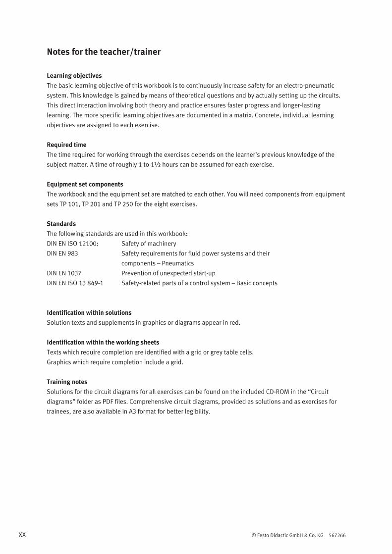
Workbook TP 250 CD-ROM included Festo Didactic 567266 en Safety in pneumatic systems 4 2 3 1 5 2 1 21 2 1 21 2 1 3 1V1 1M1 1M2 m 1A1 1V2 1M3 1V3 1V4

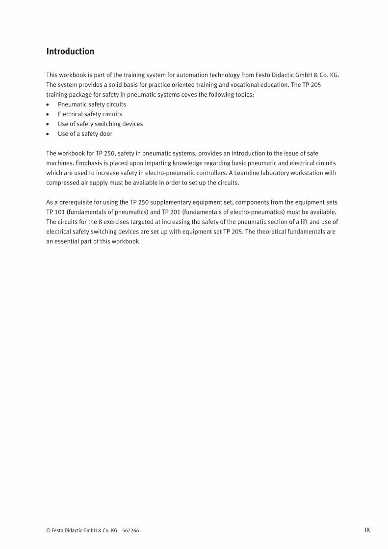
WorkbookTP 250
CD-ROM included
Festo Didactic
567266 en
Safety in pneumatic systems
4 2
315
2
1 21
2
1 21
2
1 3
1V1
1M1 1M2
m
1A1
1V2
1M3
1V3 1V4

Order number: 567266
Revision level: 06/2012
Authors: Ralph-Christoph Weber, Erwin Orendi
Graphics: Ralph-Christoph Weber
Layout: 06/2012, Ralph-Christoph Weber
© Festo Didactic GmbH & Co. KG, 73770 Denkendorf, Germany, 2013
Internet: www.festo-didactic.com
E-mail: [email protected]
The purchaser shall receive a single right of use which is non-exclusive, non-time-limited and limited
geographically to use at the purchaser's site/location as follows.
The purchaser shall be entitled to use the work to train his/her staff at the purchaser's site/location and
shall also be entitled to use parts of the copyright material as the basis for the production of his/her own
training documentation for the training of his/her staff at the purchaser's site/location with
acknowledgement of source and to make copies for this purpose. In the case of schools/technical colleges
and training centres, the right of use shall also include use by school and college students and trainees at
the purchaser's site/location for teaching purposes.
The right of use shall in all cases exclude the right to publish the copyright material or to make this available
for use on intranet, Internet and LMS platforms and databases such as Moodle, which allow access by a
wide variety of users, including those outside of the purchaser's site/location.
Entitlement to other rights relating to reproductions, copies, adaptations, translations, microfilming and
transfer to and storage and processing in electronic systems, no matter whether in whole or in part, shall
require the prior consent of Festo Didactic GmbH & Co. KG.

© Festo Didactic GmbH & Co. KG 567266 III
Table of contents
Use for intended purpose __________________________________________________________________ V
Preface ________________________________________________________________________________ VII
Introduction _____________________________________________________________________________ IX
Work and safety instructions ________________________________________________________________X
Training package for safety in pneumatic systems (TP 250) _____________________________________ XII
Learning objectives ______________________________________________________________________ XIII
Allocation of learning objectives to exercises __________________________________________________ XIV
Equipment set __________________________________________________________________________ XVI
Allocation of components to exercises – safety in pneumatic systems ______________________________ XIX
Notes for the teacher/trainer _______________________________________________________________ XX
Exercises and solutions
Exercise 1: Commissioning and risk assessment for a lift __________________________________________ 1
Exercise 2: Reducing force ___________________________________________________________________ 9
Exercise 3: Reducing speed ________________________________________________________________ 15
Exercise 4: Setting up an emergency stop function _____________________________________________ 19
Exercise 5: Failure of, and restoring, compressed air supply______________________________________ 25
Exercise 6: Failure of, and restoring, electrical power supply _____________________________________ 31
Exercise 7: Overload and diagnosis _________________________________________________________ 37
Exercise 8: Installing a cover and using the safety switching device as a door monitor ________________ 43
Optional exercise: Control with Siemens LOGO! _______________________________________________ 51
Exercises and worksheets
Exercise 1: Commissioning and risk assessment for a lift __________________________________________ 1
Exercise 2: Reducing force ___________________________________________________________________ 9
Exercise 3: Reducing speed ________________________________________________________________ 15
Exercise 4: Setting up an emergency stop function _____________________________________________ 19
Exercise 5: Failure of, and restoring, compressed air supply______________________________________ 25
Exercise 6: Failure of, and restoring, electrical power supply _____________________________________ 31
Exercise 7: Overload and diagnosis _________________________________________________________ 37
Exercise 8: Installing a cover and using the safety switching device as a door monitor ________________ 43

IV © Festo Didactic GmbH & Co. KG 567266
Basics: safety in pneumatic systems
Safety _________________________________________________________________________________ I-3
Dimensioning system components __________________________________________________________ I-7
Operating modes _______________________________________________________________________ I-11
Safe layout of a package lifting unit ________________________________________________________ I-13
Technical safety functions ________________________________________________________________ I-17
Emergency stop ________________________________________________________________________ I-49
Safety relays ___________________________________________________________________________ I-53
Protective devices ______________________________________________________________________ I-55
Basic safety tips for pneumatics ___________________________________________________________ I-59

© Festo Didactic GmbH & Co. KG 567266 V
Use for intended purpose
The training package for safety in pneumatic systems may only be used:
For its intended purpose in teaching and training applications
When its safety functions are in flawless condition
The components included in the training package are laid out in accordance with the latest technology, as
well as recognised safety rules. However, life and limb of the user and third parties may be endangered, and
the components may be impaired, if they are used improperly.
The training system from Festo Didactic has been developed and manufactured exclusively for training and
vocational education in the fields of automation and technology. The respective training companies and/or
trainers must ensure that all trainees observe the safety precautions which are described in this workbook.
Festo Didactic hereby excludes any and all liability for damages suffered by trainees, the training company
and/or any third parties, which occur during use of the equipment set in situations which serve any purpose
other than training and/or vocational education, unless such damages have been caused by Festo Didactic
due to malicious intent or gross negligence.

VI © Festo Didactic GmbH & Co. KG 567266

© Festo Didactic GmbH & Co. KG 567266 VII
Preface
Festo Didactic’s learning system for automation and technology is geared towards various educational
backgrounds and vocational requirements. Correspondingly, the training system is broken down as follows:
Technology oriented training packages
Mechatronics and factory automation
Process automation and control technology
Mobile robotics
Hybrid learning factories
The training system for automation and technology is continuously updated and expanded in accordance
with developments in the field of education, as well as actual professional practice.
The technology packages deal with various technologies including pneumatics, electro-pneumatics,
hydraulics, electro-hydraulics, proportional hydraulics, programmable logic controllers, sensor technology,
electrical engineering, electronics and electric drives.
The modular design of the training system allows for applications which go above and beyond the
limitations of the individual training packages. For example, PLC actuation of pneumatic, hydraulic and
electric drives is possible.

VIII © Festo Didactic GmbH & Co. KG 567266
All training packages are comprised of the following elements:
Hardware
Media
Seminars
Hardware
Hardware included in the training packages consists of industrial components and systems that are
specially designed for training purposes. The selection and design of the components encompassed by the
training packages are especially well matched to the projects included in the accompanying media.
Media
The media provided for the individual groups of topics are allocated to the teachware and software
categories. The practically oriented teachware includes:
Technical books and textbooks (standard works for imparting basic knowledge)
Workbooks (practical exercises with supplementary instructions and sample solutions)
Lexicons, manuals, technical books (which provide technical information on groups of topics for further
exploration)
Transparency sets and videos (for easy-to-follow, dynamic instruction)
Posters (for clear-cut representation of facts)
From the software category, programmes are made available for the following applications:
Digital training programmes (didactically and medially prepared learning content)
Simulation software
Visualisation software
Software for measurement data acquisition
Project engineering and design engineering software
Programming software for programmable logic controllers
The teaching and learning media are available in several languages. They are intended for use in classroom
instruction, but are also suitable for self-study.
Seminars
Comprehensive seminar offerings covering the contents of the training packages round out the programme
for training and vocational education.
Do you have suggestions or criticism regarding this manual?
If so, send us an e-mail at [email protected].
The authors and Festo Didactic look forward to your feedback.
© Festo Didactic GmbH & Co. KG 567266 IX
Introduction
This workbook is part of the training system for automation technology from Festo Didactic GmbH & Co. KG.
The system provides a solid basis for practice oriented training and vocational education. The TP 205
training package for safety in pneumatic systems coves the following topics:
Pneumatic safety circuits
Electrical safety circuits
Use of safety switching devices
Use of a safety door
The workbook for TP 250, safety in pneumatic systems, provides an introduction to the issue of safe
machines. Emphasis is placed upon imparting knowledge regarding basic pneumatic and electrical circuits
which are used to increase safety in electro-pneumatic controllers. A Learnline laboratory workstation with
compressed air supply must be available in order to set up the circuits.
As a prerequisite for using the TP 250 supplementary equipment set, components from the equipment sets
TP 101 (fundamentals of pneumatics) and TP 201 (fundamentals of electro-pneumatics) must be available.
The circuits for the 8 exercises targeted at increasing the safety of the pneumatic section of a lift and use of
electrical safety switching devices are set up with equipment set TP 205. The theoretical fundamentals are
an essential part of this workbook.

X © Festo Didactic GmbH & Co. KG 567266
Work and safety instructions
General
Trainees may only work with the controllers under the supervision of a trainer.
Observe specifications included in the data sheets for the individual components, and in particular all
safety instructions!
Mechanical system
Mount all of the components securely onto the slotted profile plate.
Limit switches may not be actuated frontally.
Danger of injury during troubleshooting!
Use a tool to actuate the limit switches, for example a screwdriver.
Only reach into the setup when it’s at a complete standstill.
Electrical specifications
Electrical connections may only be established and interrupted in the absence of voltage!
Use connector cables with safety plugs only for electrical connections.
Use low voltage only (max. 24 V DC).
Pneumatics
Do not exceed the maximum permissible pressure of 600 kPa (6 bar).
Do not activate compressed air until all of the tubing connections have been completed and secured.
Do not disconnect tubing while under pressure.
Danger of injury when switching compressed air on!
Cylinders may advance and retract automatically.
Danger of accident due to tubing slipping off!
– Use shortest possible tubing connections.
– Wear safety glasses.
– In the event that tubing slips off:
Switch compressed air supply off immediately.
Pneumatic circuit setup:
Connect the devices with plastic tubing with an outside diameter of 4 or 6 mm. Push the tubing into the
push-in connector as far as it will go.
Switch compressed air supply off before dismantling the circuit.
Pneumatic circuit dismantling:
Press the blue release ring down, after which the tubing can be pulled out.
© Festo Didactic GmbH & Co. KG 567266 XI
The mounting boards for the components are equipped with mounting variant A, B or C:
Variant A, snap-in system
Lightweight components that are not load-bearing (e.g. directional control valves). Simply clip the components
into the slot on the profile plate. Release the components from the slots by turning the blue lever.
Variant B, bolt system
Components with medium load capacity (e.g. actuators). These components are clamped onto the profile
plate using T-head bolts. The blue, knurled nut is used for clamping and loosening.
Variant C, screw system
For components with high load capacity and components which are seldom removed from the profile plate
(for example on-off valve with filter regulator). The components are secured with socket head screws and
T-head bolts.
Observe specifications in the data sheets regarding the individual devices.
A stopwatch is required in order to evaluate the controllers after setting them up. The stopwatch is used to:
Adjust the one-way flow control valves such that cylinder stroke times comply with the specified values
Adjust time delay valves

XII © Festo Didactic GmbH & Co. KG 567266
Training package for safety in pneumatic systems (TP 250)
The TP 250 training package consists of a multitude of individual training materials. The subject of this part
of the TP 250 training package is safety technology.
Important components of TP 250
Permanent workstation with Festo Didactic slotted profile plate
Compressor (230 V, 0.55 kW, max. 800 kPa = 8 bar)
Equipment sets or individual components (e.g. cylinders, directional control valves, preset counters,
stepper modules, logic components, pneumatic proximity switches)
Optional learning materials (e.g. optical displays, 5/3-way valve, pulling/pushing load)
Practical training models
Complete laboratory setups
Media
The teachware for the TP 250 training package consists of a workbook and a book of exercises. The
workbook includes exercise sheets for each exercise, the solutions to each individual worksheet and a CD-
ROM. A set of ready-to-use exercise sheets and worksheets is included in each workbook for all of the
exercises.
Data sheets for the hardware components are made available along with the equipment set.
Training documentation
Textbooks Pneumatics
Electropneumatics
Fundamentals
Workbooks Safety in pneumatic systems
Optional teachware FluidSIM® pneumatic simulation software
Web-based training for safety technology
Seminars
SEP-PILZ Safe pneumatic and electrical design of machines and equipment
P141 Safe circuit technology for maintenance personnel
SAFETY-AL Safety relevant circuits in pneumatics and electro-pneumatics for vocational training
SAFETY2 Safety in pneumatics and electro-pneumatics for design engineers
SAFETY3 Laying out safety circuits in accordance with DIN EN ISO 13 849-1 with the help of SISTEMA software
Please refer to the current seminar schedule for event locations, dates and prices.
You’ll find further training materials in our catalogue and on the Internet. The training system for automation
technology is continuously updated and expanded. Transparency sets, videos, CD-ROMs and DVDs, as well
as textbooks, are offered in several languages.
© Festo Didactic GmbH & Co. KG 567266 XIII
Learning objectives
Learning objectives
Be able to select the most important standards for the safety of a machine.
Be able to conduct a risk assessment for a simple machine.
Gain experience in setting up and commissioning a lift.
Gain experience in recognising points of danger at the lift and sketching them into the layout drawing.
Gain experience in reducing hazards associated with the lift.
Gain experience in assuring safe, optimised operation of the no-load and working strokes.
Know how to safeguard implemented safety measures from manipulation.
Be able to reduce risk by regulating speed.
Be able to name possible disadvantages associated with the use of the lift.
Gain experience in recognising, executing and ideally adjusting the required changes to the lift.
Gain experience in selecting an emergency stop function which is appropriate for the lift.
Be familiar with various ways of implementing this function.
Be able to set up a 2-channel pneumatic emergency stop function.
Be able to integrate a safety mushroom actuator into the electrical controls.
Be able to properly restart operation.
Be able to indicate the emergency stop status of a system.
Be able to determine how a system should perform in the event that compressed air supply should fail.
Be able to make use of sensors for detecting compressed air supply failure.
Be able to assure safe reactivation of compressed air supply.
Be familiar with required system performance in the event of electrical power failure.
Be able to make use of suitable valves in order to assure a safe emergency stop status for a system.
Be able to make use of a safety switching device and be familiar with its mode of operation.
Be able to indicate the operating state of the lift.
Be able to detect overloads by means of condition monitoring.
Be able to implement suitable measures for eliminating the cause.
Be familiar with additional ways of triggering an emergency stop.
Be able to increase the performance level of the lift by increasing its diagnostic coverage.
Be able to integrate an additional component into the system in order to increase safety.
Be familiar with additional ways of triggering an emergency stop.

XIV © Festo Didactic GmbH & Co. KG 567266
Allocation of learning objectives to exercises
Exercise 1 2 3 4 5 6 7 8
Learning objectives
Be able to select the most important standards for the safety of
a machine. •
Be able to conduct a risk assessment for a simple machine. •
Gain experience in setting up and commissioning a lift. •
Gain experience in recognising points of danger at the lift and
sketching them into the layout drawing. •
Gain experience in reducing hazards associated with the lift. •
Gain experience in assuring safe, optimised operation of the
no-load and working strokes. •
Know how to safeguard implemented safety measures from
manipulation. •
Be able to reduce risk by regulating speed. •
Be able to name possible disadvantages associated with the
use of the lift. •
Gain experience in recognising, executing and ideally adjusting
the required changes to the lift. •
Gain experience in selecting an emergency stop function which
is appropriate for the lift. •
Be familiar with various ways of implementing this function. •
Be able to set up a 2-channel pneumatic emergency stop
function. •
Be able to integrate a safety mushroom actuator into the
electrical controls. •

© Festo Didactic GmbH & Co. KG 567266 XV
Exercise 1 2 3 4 5 6 7 8
Learning objectives
Be able to properly restart operation. •
Be able to indicate the emergency stop status of a system. •
Be able to determine how a system should perform in the event
that compressed air supply should fail. •
Be able to make use of sensors for detecting compressed air
supply failure. •
Be able to assure safe reactivation of compressed air supply. •
Be familiar with required system performance in the event of
electrical power failure. •
Be able to make use of suitable valves in order to assure a safe
emergency stop status for a system. •
Be able to make use of a safety switching device and be familiar
with its mode of operation. •
Be able to indicate the operating state of the lift. •
Be able to detect overloads by means of condition monitoring. •
Be able to implement suitable measures for eliminating the
cause. •
Be able to integrate an additional component into the system in
order to increase safety. •
Be familiar with additional ways of triggering an emergency
stop. •
XVI © Festo Didactic GmbH & Co. KG 567266
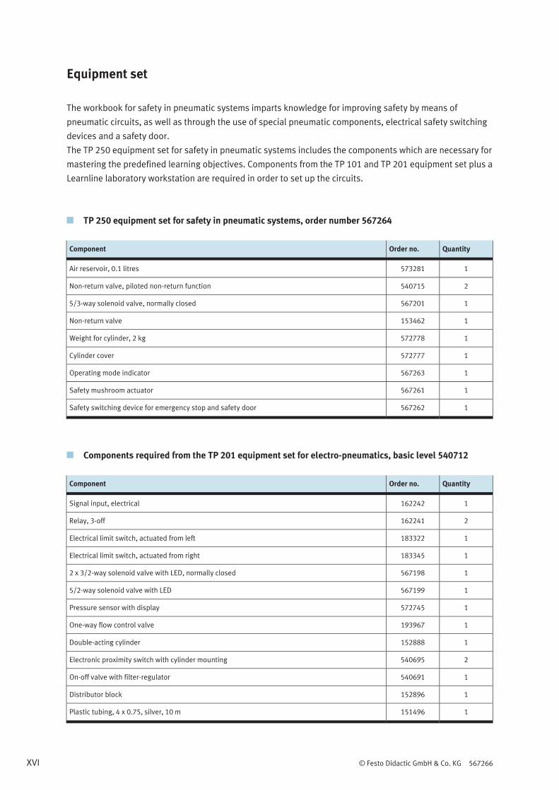
Equipment set
The workbook for safety in pneumatic systems imparts knowledge for improving safety by means of
pneumatic circuits, as well as through the use of special pneumatic components, electrical safety switching
devices and a safety door.
The TP 250 equipment set for safety in pneumatic systems includes the components which are necessary for
mastering the predefined learning objectives. Components from the TP 101 and TP 201 equipment set plus a
Learnline laboratory workstation are required in order to set up the circuits.
TP 250 equipment set for safety in pneumatic systems, order number 567264
Component Order no. Quantity
Air reservoir, 0.1 litres 573281 1
Non-return valve, piloted non-return function 540715 2
5/3-way solenoid valve, normally closed 567201 1
Non-return valve 153462 1
Weight for cylinder, 2 kg 572778 1
Cylinder cover 572777 1
Operating mode indicator 567263 1
Safety mushroom actuator 567261 1
Safety switching device for emergency stop and safety door 567262 1
Components required from the TP 201 equipment set for electro-pneumatics, basic level 540712
Component Order no. Quantity
Signal input, electrical 162242 1
Relay, 3-off 162241 2
Electrical limit switch, actuated from left 183322 1
Electrical limit switch, actuated from right 183345 1
2 x 3/2-way solenoid valve with LED, normally closed 567198 1
5/2-way solenoid valve with LED 567199 1
Pressure sensor with display 572745 1
One-way flow control valve 193967 1
Double-acting cylinder 152888 1
Electronic proximity switch with cylinder mounting 540695 2
On-off valve with filter-regulator 540691 1
Distributor block 152896 1
Plastic tubing, 4 x 0.75, silver, 10 m 151496 1

© Festo Didactic GmbH & Co. KG 567266 XVII
Components required from the TP 101 equipment set for pneumatics, basic level 540710
Component Order no. Quantity
Pressure regulator with pressure gauge 539756 1

XVIII © Festo Didactic GmbH & Co. KG 567266
Graphic symbols, equipment set
Component Graphic symbol
Non-return valve, piloted non-return function 2
1 21
5/3-way solenoid valve, normally closed
Non-return valve
Weight for cylinder, 2 kg
m
Operating mode indicator
+ + ++ + +
PRD PYE PGN
Safety mushroom actuator
Safety switching device for emergency stop and safety door
S11 S12 S21 S22 13 23 33 41
S34 Y32 14 24 34 42
Input Input K1
Reset/Start K2
Air reservoir, 0.1 litres

© Festo Didactic GmbH & Co. KG 567266 XIX
Allocation of components to exercises
Exercise 1 2 3 4 5 6 7 8
Double-acting cylinder 1 1 1 1 1 1 1 1
Weight for cylinder, 2 kg 1 1 1 1 1 1 1 1
On-off valve with filter-regulator 1 1 1 1 1 1 1 1
Distributor block 1 1 1 1 1 1 1 1
Electronic proximity switch with cylinder mounting 2 2 2 2 2 2 2 2
Signal input, electrical 1 1 1 1 1 1 1 1
Relay, 3-off 1 1 1 2 2 2 2 2
5/2-way solenoid valve with LED 1 1 1
Pressure regulator with pressure gauge 1 1 1 1 1 1 1
One-way flow control valve 2 2 2 2 2 2
Non-return valve, piloted non-return function 2 2 2 2 2
2 x 3/2-way solenoid valve with LED, normally closed 1 1 1 1 1
5/3-way solenoid valve, normally closed 1 1 1 1 1
Safety mushroom actuator 1 1 1 1
Pressure sensor with display 1 1 1 1
Air reservoir, 0.1 litres 1 1 1 1
Non-return valve 1 1 1 1
Safety switching device 1 1 1
Cylinder cover 1
Electrical limit switch, actuated from left 1
Electrical limit switch, actuated from right 1
Operating mode indicator 1 1 1
XX © Festo Didactic GmbH & Co. KG 567266
Notes for the teacher/trainer
Learning objectives
The basic learning objective of this workbook is to continuously increase safety for an electro-pneumatic
system. This knowledge is gained by means of theoretical questions and by actually setting up the circuits.
This direct interaction involving both theory and practice ensures faster progress and longer-lasting
learning. The more specific learning objectives are documented in a matrix. Concrete, individual learning
objectives are assigned to each exercise.
Required time
The time required for working through the exercises depends on the learner’s previous knowledge of the
subject matter. A time of roughly 1 to 1½ hours can be assumed for each exercise.
Equipment set components
The workbook and the equipment set are matched to each other. You will need components from equipment
sets TP 101, TP 201 and TP 250 for the eight exercises.
Standards
The following standards are used in this workbook:
DIN EN ISO 12100: Safety of machinery
DIN EN 983 Safety requirements for fluid power systems and their
components – Pneumatics
DIN EN 1037 Prevention of unexpected start-up
DIN EN ISO 13 849-1 Safety-related parts of a control system – Basic concepts
Identification within solutions
Solution texts and supplements in graphics or diagrams appear in red.
Identification within the working sheets
Texts which require completion are identified with a grid or grey table cells.
Graphics which require completion include a grid.
Training notes
Solutions for the circuit diagrams for all exercises can be found on the included CD-ROM in the “Circuit
diagrams” folder as PDF files. Comprehensive circuit diagrams, provided as solutions and as exercises for
trainees, are also available in A3 format for better legibility.

© Festo Didactic GmbH & Co. KG 567266 1
Exercise 1
Commissioning and risk assessment for a lift
Learning objectives
After completing this exercise:
You will be able to select the most important standards for the safety of a machine.
You will be able to conduct a risk assessment for a simple machine.
You will be experienced in setting up and commissioning a lift.
You will be experienced in recognising points of danger at the lift and sketching them into the layout
drawing.
Problem description
You need to set up, commission and assess a lift, and assure its safe design. Due to the fact that the lift will
be used in production, you are obligated to examine it in light of applicable safety directives, and to
minimise hazards during its use.
Layout
Lift

Exercise 1 – Commissioning and risk assessment for a lift
2 © Festo Didactic GmbH & Co. KG 567266
Prerequisites
• Equipment sets TP 250, TP 201 and a laboratory trolley with slotted profile plate must be available.
Assignments
1 Select standards which deal with safety technology and safety concepts.
2 Set up the lift and place it into service.
3 Complete a risk analysis for the system.
4 Determine possible technical means in order to reduce danger resulting from the machine.
Exercise 1 – Commissioning and risk assessment for a lift
© Festo Didactic GmbH & Co. KG 567266 3
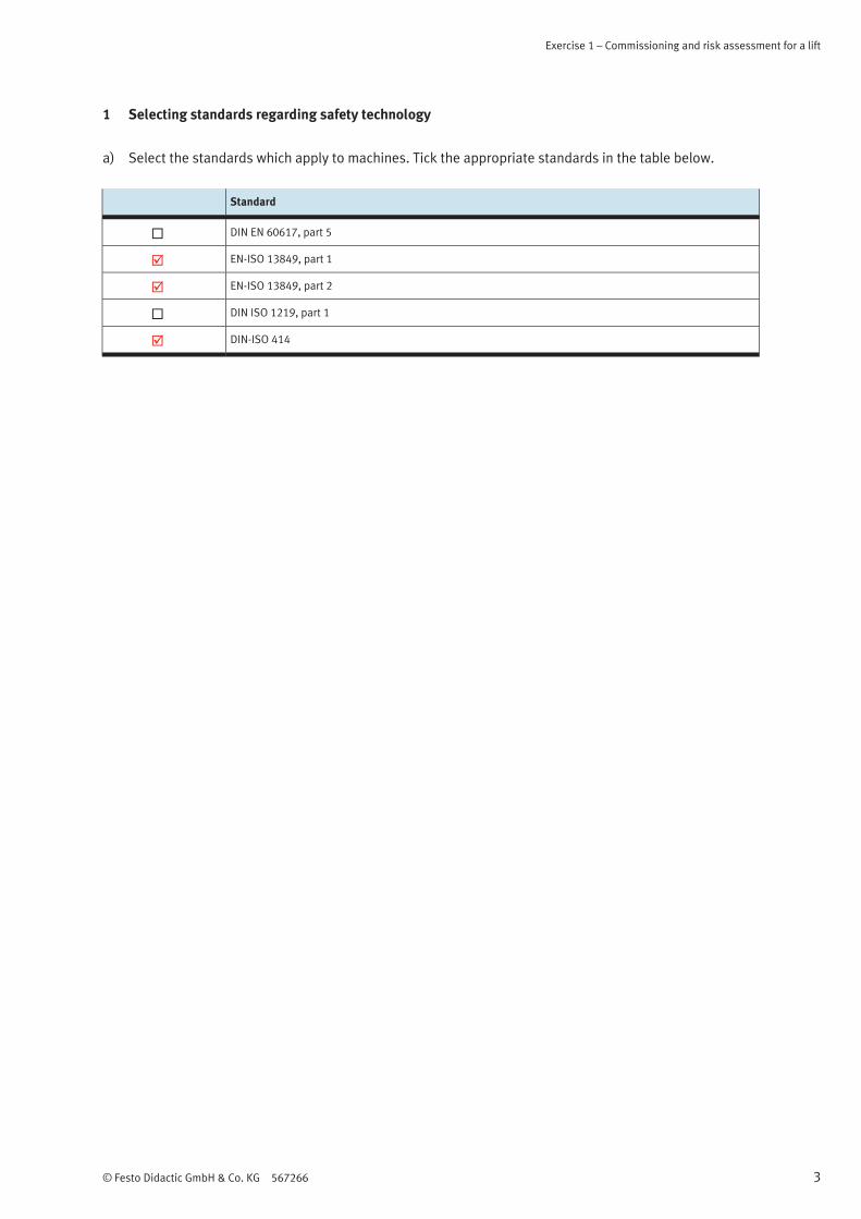
1 Selecting standards regarding safety technology
a) Select the standards which apply to machines. Tick the appropriate standards in the table below.
Standard
DIN EN 60617, part 5
EN-ISO 13849, part 1
EN-ISO 13849, part 2
DIN ISO 1219, part 1
DIN-ISO 414

Exercise 1 – Commissioning and risk assessment for a lift
4 © Festo Didactic GmbH & Co. KG 567266
2 Setting up and commissioning the lift
a) Set up the required system in accordance with the following circuit diagrams.
4 2
315
m
1A1
1V1
1M1 1M2
1B1
1B2
Pneumatic circuit diagram
Electrical circuit diagram

Exercise 1 – Commissioning and risk assessment for a lift
© Festo Didactic GmbH & Co. KG 567266 5
Note
Mount the cylinder and weight to one of the vertical columns on the laboratory trolley.
Make sure that there is an additional mounting slot to the right of the cylinder for mounting other
required components.
b) Commission the lift and describe the operating sequence.
When switch S1 is activated, solenoid valve 1V1 enables flow from 1 to 4. The piston side of the
double-acting cylinder is pressurised with compressed air and the piston rod advances.
When switch S2 is activated, solenoid valve 1V1 enables flow from 1 to 2. The piston rod side of the
double-acting cylinder is pressurised with compressed air and the piston rod retracts.
Exercise 1 – Commissioning and risk assessment for a lift
6 © Festo Didactic GmbH & Co. KG 567266
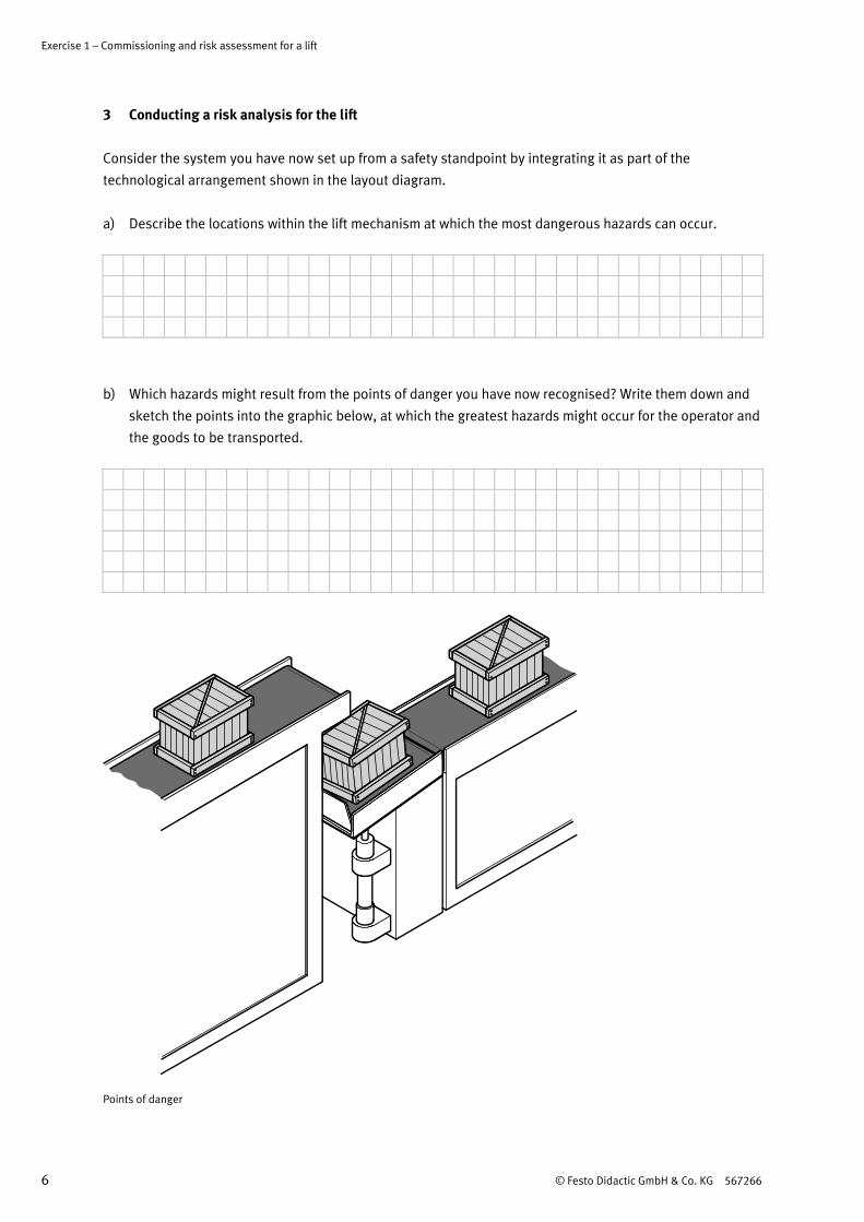
3 Conducting a risk analysis for the lift
Consider the system you have now set up from a safety standpoint by integrating it as part of the
technological arrangement shown in the layout diagram.
a) Describe the locations within the lift mechanism at which the most dangerous hazards can occur.
The cylinder advances and retracts at high speed, and with full force. Furthermore, it stops and starts
abruptly. Very high forces occur as a result which may cause injury if a person reaches into the travel
path. This is particularly true at the edges of the belt conveyors.
The goods to be transported are thrown from the lifting platform due to abrupt starts and stops.
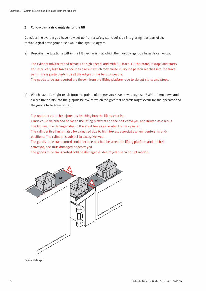
b) Which hazards might result from the points of danger you have now recognised? Write them down and
sketch the points into the graphic below, at which the greatest hazards might occur for the operator and
the goods to be transported.
The operator could be injured by reaching into the lift mechanism.
Limbs could be pinched between the lifting platform and the belt conveyor, and injured as a result.
The lift could be damaged due to the great forces generated by the cylinder.
The cylinder itself might also be damaged due to high forces, especially when it enters its end-
positions. The cylinder is subject to excessive wear.
The goods to be transported could become pinched between the lifting platform and the belt
conveyor, and thus damaged or destroyed.
The goods to be transported cold be damaged or destroyed due to abrupt motion.
Points of danger
Exercise 1 – Commissioning and risk assessment for a lift
© Festo Didactic GmbH & Co. KG 567266 7
4 Measures in order to reduce danger
a) Write down possible measures for reducing danger at the lift.
Possible technical measures include:
Reduce the force of the cylinder piston.
Reduce piston speed.
Eliminate abrupt starting and stopping.
Implement measures which assure a safe system status in the event that electrical or pneumatic
supply power should fail.
Design engineering measures targeted at enhancing system safety.

Exercise 1 – Commissioning and risk assessment for a lift
8 © Festo Didactic GmbH & Co. KG 567266

© Festo Didactic GmbH & Co. KG 567266 1
Table of contents
Exercises and worksheets
Exercise 1: Commissioning and risk assessment for a lift __________________________________________ 3
Exercise 2: Reducing force _________________________________________________________________ 11
Exercise 3: Reducing speed ________________________________________________________________ 17
Exercise 4: Setting up an emergency stop function _____________________________________________ 21
Exercise 5: Failure of, and restoring, compressed air supply______________________________________ 27
Exercise 6: Failure of, and restoring, electrical power supply _____________________________________ 33
Exercise 7: Overload and diagnosis _________________________________________________________ 39
Exercise 8: Installing a cover and using the safety switching device as a door monitor ________________ 45

2 © Festo Didactic GmbH & Co. KG 567266

© Festo Didactic GmbH & Co. KG 567266 1
Exercise 1
Commissioning and risk assessment for a lift
Learning objectives
After completing this exercise:
You will be able to select the most important standards for the safety of a machine.
You will be able to conduct a risk assessment for a simple machine.
You will be experienced in setting up and commissioning a lift.
You will be experienced in recognising points of danger at the lift and sketching them into the layout
drawing.
Problem description
You need to set up, commission and assess a lift, and assure its safe design. Due to the fact that the lift will
be used in production, you are obligated to examine it in light of applicable safety directives, and to
minimise hazards during its use.
Layout
Lift
Exercise 1 – Commissioning and risk assessment for a lift
2 © Festo Didactic GmbH & Co. KG 567266
Prerequisites
• Equipment sets TP 250, TP 201 and a laboratory trolley with slotted profile plate must be available.
Assignments
1 Select standards which deal with safety technology and safety concepts.
2 Set up the lift and place it into service.
3 Complete a risk analysis for the system.
4 Determine possible technical means in order to reduce danger resulting from the machine.

Exercise 1 – Commissioning and risk assessment for a lift
© Festo Didactic GmbH & Co. KG 567266 3
1 Selecting standards regarding safety technology
a) Select the standards which apply to machines. Tick the appropriate standards in the table below.
Norm
DIN EN 60617 part 5
EN-ISO 13849 part 1
EN-ISO 13849 part 2
DIN ISO 1219 part 1
DIN-ISO 414

Exercise 1 – Commissioning and risk assessment for a lift
4 © Festo Didactic GmbH & Co. KG 567266
2 Setting up and commissioning the lift
a) Set up the required system in accordance with the following circuit diagrams.
4 2
315
m
1A1
1V1
1M1 1M2
1B1
1B2
Pneumatic circuit diagram
Electrical circuit diagram

Exercise 1 – Commissioning and risk assessment for a lift
© Festo Didactic GmbH & Co. KG 567266 5
Note
Mount the cylinder and weight to one of the vertical columns on the laboratory trolley.
Make sure that there is an additional mounting slot to the right of the cylinder for mounting other
required components.
b) Commission the lift and describe the operating sequence.
Exercise 1 – Commissioning and risk assessment for a lift
6 © Festo Didactic GmbH & Co. KG 567266
3 Conducting a risk analysis for the lift
Consider the system you have now set up from a safety standpoint by integrating it as part of the
technological arrangement shown in the layout diagram.
a) Describe the locations within the lift mechanism at which the most dangerous hazards can occur.
b) Which hazards might result from the points of danger you have now recognised? Write them down and
sketch the points into the graphic below, at which the greatest hazards might occur for the operator and
the goods to be transported.
Points of danger
Exercise 1 – Commissioning and risk assessment for a lift
© Festo Didactic GmbH & Co. KG 567266 7
4 Measures in order to reduce danger
a) Write down possible measures for reducing danger at the lift.

Exercise 1 – Commissioning and risk assessment for a lift
8 © Festo Didactic GmbH & Co. KG 567266

© Festo Didactic GmbH & Co. KG 567266 I-1
Table of contents
Safety in pneumatic systems
1 Safety ____________________________________________________________________________ 3
1.1 Safety in pneumatic systems ________________________________________________________ I-3
1.2 Safety related directives ____________________________________________________________ I-4
2 Dimensioning system components ___________________________________________________ I-6
2.1 Dimensioning the cylinder __________________________________________________________ I-7
2.2 Selection of a appropriate valve _____________________________________________________ I-9
3 Operating modes ________________________________________________________________ I-10
3.1 Initial position / standstill _________________________________________________________ I-10
3.2 Normal operation ________________________________________________________________ I-10
3.3 Setup and service operating mode __________________________________________________ I-10
3.4 Emergency operation _____________________________________________________________ I-10
4 Safe layout of a package lifting unit _________________________________________________ I-11
4.1 Danger zones ___________________________________________________________________ I-11
4.2 Risk analyses ___________________________________________________________________ I-12
4.3 Accident prevention measures ______________________________________________________ I-12
5 Technical safety functions _________________________________________________________ I-14
5.1 Reduced speed __________________________________________________________________ I-14
5.2 Supply air flow control ____________________________________________________________ I-16
5.3 Exhaust air flow control ___________________________________________________________ I-16
5.4 Exhaust and supply air flow control __________________________________________________ I-17
5.5 Reduce pressure _________________________________________________________________ I-19
5.6 Stop, suspend or disable motion ____________________________________________________ I-22
5.7 Directional control valve, mid-position closed _________________________________________ I-22
5.8 Piloted non-return valve ___________________________________________________________ I-23
5.9 Clamping unit ___________________________________________________________________ I-27
5.10 Brake units _____________________________________________________________________ I-29
5.11 End position lock ________________________________________________________________ I-31
5.12 Shut-off valves __________________________________________________________________ I-32
5.13 Two-hand operation ______________________________________________________________ I-32
5.14 Exhaust ________________________________________________________________________ I-33
5.15 Pressurisation ___________________________________________________________________ I-34
5.16 Force-free ______________________________________________________________________ I-35
5.17 Reverse motion __________________________________________________________________ I-38
5.18 Maintain pressure ________________________________________________________________ I-38
5.19 Tamper-proofing, prevention of unexpected start-up ___________________________________ I-40
5.20 Lockout/tagout devices ___________________________________________________________ I-41
Content
I-2 © Festo Didactic GmbH & Co. KG 567266
6 Emergency stop _________________________________________________________________ I-43
6.1 Definition of emergency stop _______________________________________________________ I-43
6.2 What must happen after the emergency stop function has been activated? _________________ I-44
7 Safety relay ____________________________________________________________________ I-46
8 Protective devices _______________________________________________________________ I-48
8.1 Types of protective devices ________________________________________________________ I-48
8.2 Active optoelectronic protective devices (light barriers and laser scanners) _________________ I-49
8.3 Safety camera systems ____________________________________________________________ I-50
8.4 Pressure sensitive safety mats _____________________________________________________ I-50
9 Basic safety tips for pneumatics ____________________________________________________ I-51

© Festo Didactic GmbH & Co. KG 567266 I-3
1 Safety
1.1 Safety in pneumatic systems
Knowledge regarding the safe layout of pneumatic circuits in machines is imparted to employees by means
of this training package.
Compressed air is capable of storing large amounts of energy which can be released again very quickly. In
the field of pneumatics, compressed air is the medium which makes it possible to run the system. Due to the
tremendous forces which occur at high speeds, pneumatic equipment can be very dangerous.
For this reason, machines must be designed to assure the safety of human beings and animals, to avoid
property damage and to protect the environment. The utmost goal is to prevent any and all types of
personal injury and property damage. Safety goals can be listed as follows:
Personal safety
Environmental protection
Explosion protection and fire prevention
Noise reduction
Machine safety
All persons involved with mechanical engineering have to deal with safety issues, and thus with standards
as well. It must be assured that effective safety solutions do not represent obstacles to efficient production
but rather, on the contrary, contribute to making production more economic and stable. The EU issues
general safety goals in the form of directives. The EU machinery directive describes measures to be
implemented for the assurance of safety. This directive stipulates a risk analysis and a risk assessment for
machines. Clearly, there can be no standard concept for achieving this objective. The risk analysis and the
risk assessment must be conducted for each machine for a great variety of applications.

Safety
I-4 © Festo Didactic GmbH & Co. KG 567266
If we want to familiarise ourselves with term safety, we have to thoroughly examine the meaning of this
word. The following questions frequently arise when a machine is being developed.
Is the machine still safe?
Is the machine already unsafe?
Is it dangerous?
The problem is that there is no conclusive definition of the word safety. Anyone who examines a given
machine can interpret the word safety in accordance with his or her own criteria.
Example:
Most people die in bed. Does this mean that we should consider beds deadly or dangerous? Would it be
wise to avoid lying in bed? Although this is an extreme example, the same type of approach can frequently
be detected when people discuss the dangers which result from machines.
1.2 Safety related directives
Although the above described conflict is based on the fact that there is no definition for the word safety,
standards have been issued in order to maintain certain levels of safety.
These standards can be broken down as follows:
Type A: basic safety standards
DIN EN ISO 12100 (General principles for design)
ISO 14121 (Risk assessment)
DIN EN 4414 (General rules for drafting any laying out safety requirements for pneumatic systems and
their components)
Type B1: standards related to specific safety aspects
DIN EN 294 (Safety of machinery - safety distances to prevent danger zones from being reached by the
upper limbs)
DIN EN 349 (Safety of machinery - Minimum gaps to avoid crushing of parts of the human body)
DIN EN ISO 13849-1 (Safety-related parts of control systems - Part 1: General principles for design)
DIN EN ISO 13849-2 (Safety-related parts of control systems - Part 2: Validation)
DIN EN 999 (The positioning of protective equipment in respect of approach speeds of parts of the
human body)
DIN EN 1037 (Prevention of unexpected start-up)
DIN EN 60204 (Electrical equipment of machines)


