12

2 EATON Weatherhead ET4001 Crimp Machine Operator´s Manual W-EQCR-TM022-E2 December 2013
Table of Contents
1. PrEvEnT unauThOrizEd OPEraTiOn. do not permit anyone to operate this equipment unless they have read and thoroughly understood this manual.
2. WEar safETy glassEs.
3. avOid PinCh POinTs. do not rest your hand on the crimp ring. Keep your hands clear of all moving parts. do not allow anyone, other than the operator, close to the equipment while it is in operation.
4. MainTain diEs WiTh CarE. dies used in the ET4001 crimp machine are hardened
steel, offering the best combination of strength and wear resistance for long life. hardened dies are generally brittle and care should be taken to avoid any sharp impact. never strike a die with a hardened instrument.
5. usE Only sPECifiEd EaTOn PrOduCTs. Make hose assemblies using only Eaton's Weatherhead hose and Eaton fittings specified for this assembly equipment.
6. vErify COrrECT CriMP diaMETErs. Check and verify correct crimp diameters of all fittings after crimping.
do not put any hose assemblies into service if the crimp diameters do not meet Eaton crimp specifications.
7. MaKE surE all diEs arE COMPlETEly in PlaCE, the spacer ring rests against the locator bracket, and the pusher halves are closed before crimping.
8. dO nOT OvEr PrEssurizE. do not exceed the 5,000 psi hydraulic pressure supplied to the machine
9. diE ChangE. dO nOT insErT/rEMOvE diEs WhilE ThE POWEr is On Or MaChinE is in OPEraTiOn.
10. sECurE ThE EquiPMEnT TO a sTablE WOrK surfaCE. Prior to operation, secure the crimp machine to a stable work surface to prevent the equipment from tipping. see pages 4-5 for mounting instructions.
11. unPlug ThE POWEr suPPly WhEn nOT in usE.
12. KEEP WOrK arEa ClEan. Cluttered areas and benches invite accidents.
13. dO nOT OPEraTE WiThOuT ThE basE adaPTEr ring in PlaCE.
Safety InstructionsET4001 Crimp Machine
WARNING
Eaton's Weatherhead hose and Eaton hose fittings should only be assembled using Eaton approved assembly equipment. do not use any combinations of Eaton's Weatherhead hose, Eaton hose fittings, or Eaton assembly equipment with hose, hose fittings, or assembly equipment supplied by another manufacturer.
Eaton hereby disclaims any obligation or liability (including incidental and consequential damages) arising from breach of contract, warranty, or tort (under negligence or strict liability theories) should Eaton hose, Eaton hose fittings, or Eaton assembly equipment be used with any hose, hose fittings, or assembly equipment supplied by another manufacturer, or in the event that product instructions for each specified hose assembly are not followed. (reference saE J1273 – recommended Practice for hydraulic hose assemblies).
WARNING
failure to follow Eaton processes and product instructions and limitations could lead to premature hose assembly failures, resulting in property damage, serious injury, or death.
Eaton fitting tolerances are engineering to match Eaton's Weatherhead hose tolerances. The combination or use of Eaton's Weatherhead hose and hose fittings supplier by another manufacturer may result in the production of unreliable and/or unsafe hose assemblies and is neither recommended nor authorized by Eaton.
read and understand the operator’s manual before attempting to operate any equipment.
Section Page
Safety Instructions 2Specifications and Equipment 3
ET4001 Crimp Machine 3ET4001P-002 Electric Pump 3
Shop/Work Table Mounting Instructions 4 - 5Check-out Procedure 5Operating Instructions 6 - 9
ET4000ar-001: using ET4000ar-001 base adapter rings 6ET4000ar-002: using ET4000ar-002 base adapter rings for heavy 4-Wire 7
and 6-Wire fittings (-20 thru -32 Collets)T-410-25 adapter ring 8Coll-O-Crimp spacer ring and nominal Crimp diameter Measurement 9
Troubleshooting Procedures 11Repair and Replacement Items 11

3EATON Weatherhead ET4001 Crimp Machine Operator´s Manual W-EQCR-TM022-E2 December 2013
Specifications and EquipmentET4001 Crimp Machine and Accessories
ET4001 Crimp Machine
ET4001 is ideal for factory high performance machine operations, construction and mine locations. The ET4001 press offers crimping capabilities through 2” i.d. six spiral hose.
Weight 500 lbs.
Size 30”high, 22”deep, 12”wide
ET4001P-002 Electric Pump
The Eaton ET4001P-002 power unit is ideally suited for use with the ET4001 press. it features a two-stage pump providing high flow at low pressure for fast ram approach and low flow at high pressure for actual crimping.
Dimensions 7½” high, 10” wide, 22” long
Weight 75 lbs.
Pressure 5000 psi
Reservoir Capacity 6 Quarts
Outlet Port Size ¾-16 Straight Thread O-ring
Motor 1HP, 3450 RPM, 220 volts, 60 cycle, Single Phase
Hydraulic Oil ISO 32 (SAE 10W)
Flow 2.6 GPM to 900 psi. 0.6 GPM above 900 psi
CAUTION
The ET4001P-002 Electric Pump has the relief valve set at 5,000 psi. damage to the press will result and the warranty may be voided if higher pressures are used. requires individual 20 amp service breaker (220 v).
Components Needed: T-410-22 hose assembly (1) included in ET4001-004 COC Package
4 EATON Weatherhead ET4001 Crimp Machine Operator´s Manual W-EQCR-TM022-E2 December 2013
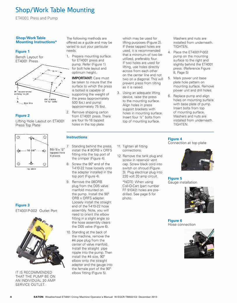
Figure 3
ET4001P-002 Outlet Port
Shop/Work Table MountingET4001 Press and Pump
The following methods are offered as a guide and may be varied to suit your particular needs.
1. Prepare mounting surface for ET4001 press and pump. refer (figure 1) for bolt hole layout and optimum height.
IMPORTANT: Care must be taken to insure that the surface to which the press is bolted is capable of supporting the weight of the press (approximately 500 lbs.) and pump (approximately 75 lbs).
2. remove shipping carton from ET4001 press. There are four 5/8-18 tapped holes in the top plate
which may be used for lifting purposes (figure 2). if these tapped holes are used, it is recommended that a minimum of two be utilized, preferably four. if two holes are used for lifting, use holes directly across from each other on the center line and not two on a diagonal. This will prevent press from tilting as it is raised.
3. using an adequate lifting device, raise the press to the mounting surface. align holes in press support brackets with holes in mounting surface. insert four ½” bolts from top of mounting surface.
Washers and nuts are installed from underneath. TighTEn.
4. Place the ET4001P-002 pump on the mounting surface to the right and slightly behind the ET4001 press. (reference figure 8, Page 5)
5. Mark power unit base plate hole pattern on mounting surface. remove power unit and drill holes.
6. replace pump and align holes on mounting surface with base plate of pump. insert bolts from top of mounting surface. Washers and nuts are installed from underneath. TighTEn.
Figure 1
bench layout for ET4001 Press
Figure 4Connection at top plate
Figure 5gauge installation
Figure 6hose connection
Figure 2
lifting hole layout on ET4001 Press Top Plate
Shop/Work Table Mounting Instructions*
iT is rECOMMEndEd ThaT ThE PuMP bE On an individual 20 aMP sErviCE OuTlET.
7. standing behind the press, install the # 8Orb x Orfs fitting into the top port of the crimper (figure 4).
8. screw the 90º end of the T-410-22 hose loosely onto the adapter installed in the top port (figure 4).
9. remove the 08Orb plug from the d05 valve manfold mounted on the pump. install the 90º Orb x Orfs adapter. loosely install the straight end of the T-410-22 hose assembly. note, you will need to orient the elbow fitting in a slight angle so the hose assembly clears the d05 valve (figure 6).
10. standing at the back of the machine, remove the #4 pipe plug from the center of valve manfold. install the straight pipe nipple into the pump. Then install the #4 size, 90º elbow onto the straight adapter and the gauge into the female port of the 90º elbow fitting (figure 5).
11. Tighten all fitting connections.
12. remove the tank plug and screw in reservoir vent cap. screw black cord into switch on shroud (figure 3). Plug electrical plug into 220 volt 20 amp circuit.
*nOTE: When using Coll-O-Cart (part number ff 91042) holes are pre-drilled. see page 5 for photo.
Instructions
5EATON Weatherhead ET4001 Crimp Machine Operator´s Manual W-EQCR-TM022-E2 December 2013
Shop/Work Table Mounting and Check-Out Procedure ET4001P-002 Electric Pump
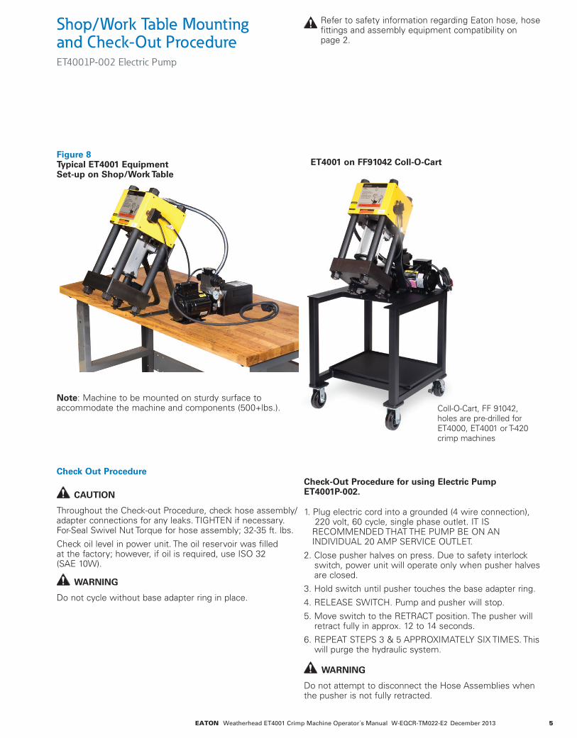
Figure 8 Typical ET4001 Equipment Set-up on Shop/Work Table
ET4001 on FF91042 Coll-O-Cart
refer to safety information regarding Eaton hose, hose fittings and assembly equipment compatibility on page 2.
CAUTION
Throughout the Check-out Procedure, check hose assembly/adapter connections for any leaks. TighTEn if necessary. for-seal swivel nut Torque for hose assembly; 32-35 ft. lbs.
Check oil level in power unit. The oil reservoir was filled at the factory; however, if oil is required, use isO 32 (saE 10W).
WARNING
do not cycle without base adapter ring in place.
WARNING
do not attempt to disconnect the hose assemblies when the pusher is not fully retracted.
Check Out ProcedureCheck-Out Procedure for using Electric Pump ET4001P-002.
1. Plug electric cord into a grounded (4 wire connection), 220 volt, 60 cycle, single phase outlet. iT is rECOMMEndEd ThaT ThE PuMP bE On an individual 20 aMP sErviCE OuTlET.
2. Close pusher halves on press. due to safety interlock switch, power unit will operate only when pusher halves are closed.
3. hold switch until pusher touches the base adapter ring.
4. rElEasE sWiTCh. Pump and pusher will stop.
5. Move switch to the rETraCT position. The pusher will retract fully in approx. 12 to 14 seconds.
6. rEPEaT sTEPs 3 & 5 aPPrOXiMaTEly siX TiMEs. This will purge the hydraulic system.
Coll-O-Cart, ff 91042, holes are pre-drilled for ET4000, ET4001 or T-420 crimp machines
Note: Machine to be mounted on sturdy surface to accommodate the machine and components (500+lbs.).
6 EATON Weatherhead ET4001 Crimp Machine Operator´s Manual W-EQCR-TM022-E2 December 2013
Operating Instructions Using ET4000AR-001
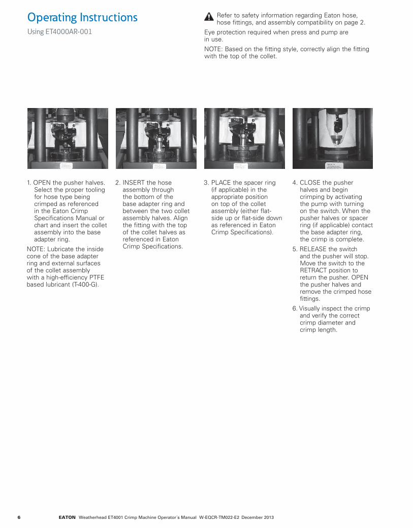
1. OPEn the pusher halves. select the proper tooling for hose type being crimped as referenced in the Eaton Crimp specifications Manual or chart and insert the collet assembly into the base adapter ring.
nOTE: lubricate the inside cone of the base adapter ring and external surfaces of the collet assembly with a high-efficiency PTfE based lubricant (T-400-g).
2. insErT the hose assembly through the bottom of the base adapter ring and between the two collet assembly halves. align the fitting with the top of the collet halves as referenced in Eaton Crimp specifications.
3. PlaCE the spacer ring (if applicable) in the appropriate position on top of the collet assembly (either flat-side up or flat-side down as referenced in Eaton Crimp specifications).
4. ClOsE the pusher halves and begin crimping by activating the pump with turning on the switch. When the pusher halves or spacer ring (if applicable) contact the base adapter ring, the crimp is complete.
5. rElEasE the switch and the pusher will stop. Move the switch to the rETraCT position to return the pusher. OPEn the pusher halves and remove the crimped hose fittings.
6. visually inspect the crimp and verify the correct crimp diameter and crimp length.
refer to safety information regarding Eaton hose, hose fittings, and assembly compatibility on page 2.
Eye protection required when press and pump are in use.
nOTE: based on the fitting style, correctly align the fitting with the top of the collet.

7EATON Weatherhead ET4001 Crimp Machine Operator´s Manual W-EQCR-TM022-E2 December 2013
Operating Instructions Using ET4000AR-002 for Heavy 4-Wire and 6-Wire Fittings (-20 thru -32 Collets)
1. OPEn the pusher halves.
nOTE: lubricate the inside cone of the base adapter ring and external surfaces of the collet assembly with a high-efficiency PTfE based lubricant (T-400-g).
2. Pull the pusher tab upward. The pusher tab is located behind the top of the pushers at the back of the machine.
3. slidE pushers to side while holding the pusher tab up.
4. Pull spacer ring locator bracket upward. Turn the locator bracket 90˚.
5. rEMOvE the base adapter ring from base plate and PlaCE the ET4000ar-002 base adapter ring inside the base plate.
nOTE: lubricate the outside diameter of base adapter ring before placing into the base plate.
6. Turn locator bracket 90˚ until aligned properly.
7. sElECT the proper collet assembly for hose type being crimped as referenced in the Crimp specifications Manual or chart and insert the collet assembly into the base adapter ring.
nOTE: lubricate the inside cone of the base adapter ring and external surfaces of the collet assembly with a high-efficiency PTfE-based lubricant (T-400-g).
8. insErT the hose assembly through the bottom of the base adapter ring and between the two collet assembly halves. To achieve a full flat crimp for 4sP/6sP fittings, locate the bottom of the socket approximately 1/8" (3mm) from the bottom edge of the collet halves as referenced in Eaton Crimp specifications.
9. ClOsE the pusher halves and begin crimping by activating the pump with turning on the switch. When the pusher halves or spacer ring (if applicable) contacts the base adapter ring, the crimp is complete.
10. rElEasE the switch and the pusher will stop. Move the switch to the rETraCT position to return the pusher. OPEn the pusher halves and remove the crimped hose assembly.
11. visually inspect the crimp and verify the correct crimp diameter and crimp length.
refer to safety information regarding Eaton hose, hose fittings, and assembly compatibility on page 2.
Eye protection required when press and pump are in use.
nOTE: based on the fitting style, correctly align the fitting with the top of the collet.
8 EATON Weatherhead ET4001 Crimp Machine Operator´s Manual W-EQCR-TM022-E2 December 2013
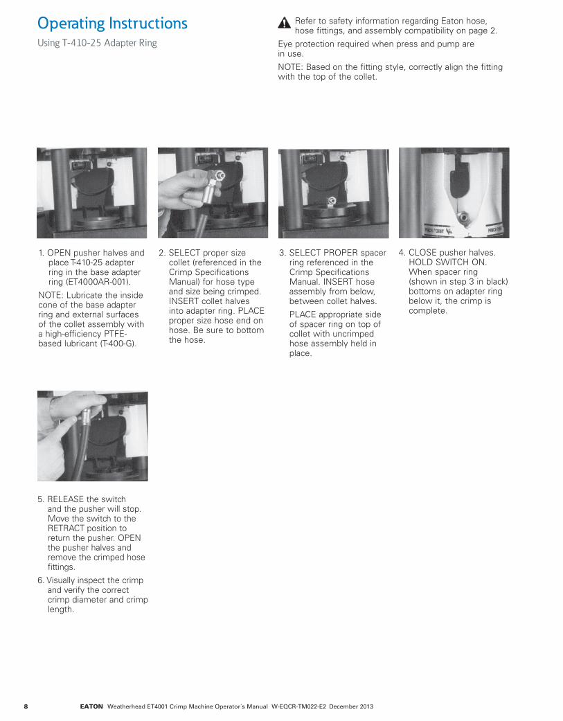
Operating Instructions Using T-410-25 Adapter Ring
1. OPEn pusher halves and place T-410-25 adapter ring in the base adapter ring (ET4000ar-001).
nOTE: lubricate the inside cone of the base adapter ring and external surfaces of the collet assembly with a high-efficiency PTfE-based lubricant (T-400-g).
2. sElECT proper size collet (referenced in the Crimp specifications Manual) for hose type and size being crimped. insErT collet halves into adapter ring. PlaCE proper size hose end on hose. be sure to bottom the hose.
3. sElECT PrOPEr spacer ring referenced in the Crimp specifications Manual. insErT hose assembly from below, between collet halves.
PlaCE appropriate side of spacer ring on top of collet with uncrimped hose assembly held in place.
5. rElEasE the switch and the pusher will stop. Move the switch to the rETraCT position to return the pusher. OPEn the pusher halves and remove the crimped hose fittings.
6. visually inspect the crimp and verify the correct crimp diameter and crimp length.
4. ClOsE pusher halves. hOld sWiTCh On. When spacer ring (shown in step 3 in black) bottoms on adapter ring below it, the crimp is complete.
refer to safety information regarding Eaton hose, hose fittings, and assembly compatibility on page 2.
Eye protection required when press and pump are in use.
nOTE: based on the fitting style, correctly align the fitting with the top of the collet.
9EATON Weatherhead ET4001 Crimp Machine Operator´s Manual W-EQCR-TM022-E2 December 2013
Operating Instructions Coll-O-Crimp Spacer Ring and Nominal Crimp Diameter Measurement
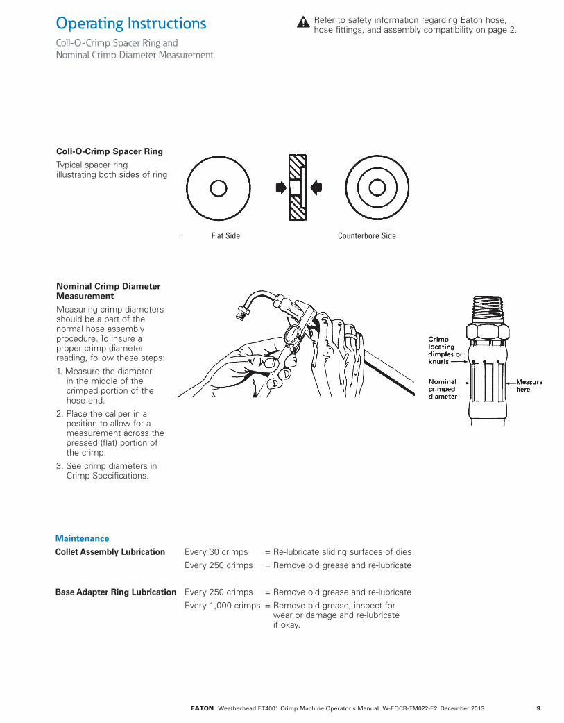
Coll-O-Crimp Spacer Ring
Typical spacer ring illustrating both sides of ring
Nominal Crimp Diameter Measurement
Measuring crimp diameters should be a part of the normal hose assembly procedure. To insure a proper crimp diameter reading, follow these steps:
1. Measure the diameter in the middle of the crimped portion of the hose end.
2. Place the caliper in a position to allow for a measurement across the pressed (flat) portion of the crimp.
3. see crimp diameters in Crimp specifications.
Maintenance
Collet Assembly Lubrication Every 30 crimps = re-lubricate sliding surfaces of dies
Every 250 crimps = remove old grease and re-lubricate
Base Adapter Ring Lubrication Every 250 crimps = remove old grease and re-lubricate
Every 1,000 crimps = remove old grease, inspect for wear or damage and re-lubricate if okay.
Flat Side Counterbore Side
refer to safety information regarding Eaton hose, hose fittings, and assembly compatibility on page 2.
10 EATON Weatherhead ET4001 Crimp Machine Operator´s Manual W-EQCR-TM022-E2 December 2013
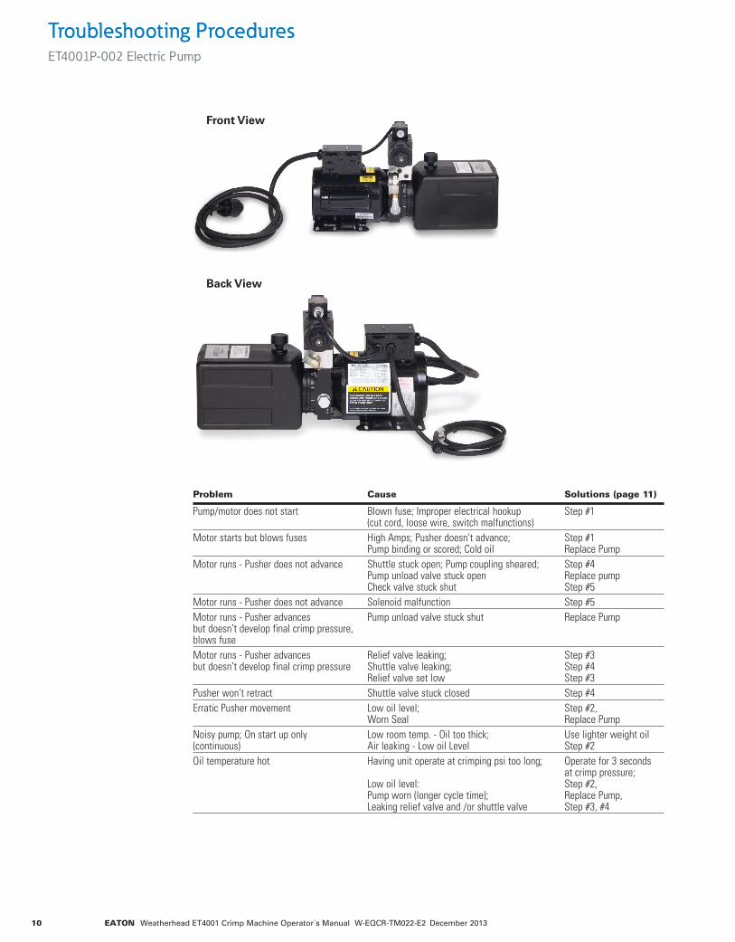
Troubleshooting ProceduresET4001P-002 Electric Pump
Problem Cause Solutions (page 11)
Pump/motor does not start Blown fuse; Improper electrical hookup Step #1 (cut cord, loose wire, switch malfunctions)Motor starts but blows fuses High Amps; Pusher doesn’t advance; Step #1 Pump binding or scored; Cold oil Replace PumpMotor runs - Pusher does not advance Shuttle stuck open; Pump coupling sheared; Step #4 Pump unload valve stuck open Replace pump Check valve stuck shut Step #5Motor runs - Pusher does not advance Solenoid malfunction Step #5Motor runs - Pusher advances Pump unload valve stuck shut Replace Pump but doesn’t develop final crimp pressure, blows fuseMotor runs - Pusher advances Relief valve leaking; Step #3 but doesn’t develop final crimp pressure Shuttle valve leaking; Step #4 Relief valve set low Step #3Pusher won’t retract Shuttle valve stuck closed Step #4Erratic Pusher movement Low oil level; Step #2, Worn Seal Replace PumpNoisy pump; On start up only Low room temp. - Oil too thick; Use lighter weight oil (continuous) Air leaking - Low oil Level Step #2Oil temperature hot Having unit operate at crimping psi too long; Operate for 3 seconds at crimp pressure; Low oil level: Step #2, Pump worn (longer cycle time); Replace Pump, Leaking relief valve and /or shuttle valve Step #3, #4
Back View
Front View

11EATON Weatherhead ET4001 Crimp Machine Operator´s Manual W-EQCR-TM022-E2 December 2013
Step 1: Check – look for fuse, loose wire connections, switch malfunctions or damaged cord. Check for proper installation of a 220 volt circuit.
Step 2: Check oil level – after assembly and system has been purged of air, the fluid level should be½” from top of reservoir. Clean, anti-wear type, having a 300 ssu/100˚ hydraulic oil is recommended (isO 32 or saE 10W). Oil is needed to:
1. Transmit power easily through system
2. lubricate moving parts
3. Provide seal clearances between parts
4. Cool or dissipate heat
Step 3: Clean or reset relief valve – a 6,000 psi pressure gauge, a 5/16” allen wrench, a 1” socket and a screwdriver are required. remove cap from relief valve. remove
adjustment screw, spring and ball. ball should be attached to spring. Check ball and seat for possible scoring. replace spring and ball in cavity. insert a small punch through spring against ball. give punch a moderate tap to seat ball. return adjustment screw to original position making sure adjustment screw is at least one turn from bottoming. remove 1/4” nPTf plug from port above check valve and install a 6,000 psi pressure gage. With 6,000 psi pressure gauge in place, operate unit to full crimping position. gauge should read approximately 5,000 psi. To raise setting, turn screw inward (clockwise); to lower, turn screw outward (counterclockwise) in ¼ turn increments. after each adjustment, recycle and read gauge for proper setting. run a cycle of the crimping system for
final gauge reading before removing gauge and reinstalling pipe plug.
Step 4: shuttle valve – if the shuttle valve is in a closed position and the ET4001 pusher will not retract, it may be helpful to tap the shuttle valve cap several times to dislodge any silt that may be causing the stem to bind. if this does not free the valve and allow the pusher to retract, use extreme caution prior to proceeding with shuttle valve removal as the system is still under pressure. it may be advisable to relieve pressure at a hose connection to avoid an oil bath. after pressure is removed from system, remove cap and valve cartridge. soak cartridge in a PETrOlEuM basEd sOlvEnT Only (clean stoddard solvent). do not use Triethene, gasoline or Paint Thinner as they will
damage the O-ring seals. if cartridge disassembly is required use care in removing stem as it has a .0005 metal seal fit. rotate stem in solvent and push from seat end to remove from cartridge. do not lose the loose ball. Wash parts in clean solvent and examine for any surface markings. if necessary, polish with a fine crocus cloth. after final cleaning, reassembly cartridge. shake cartridge and check for free movement of ball and stem. replace cartridge if not functional at this point. reassemble shuttle valve into its cavity and check crimping cycle prior to using system.
IMPORTANT: Pressure must be relieved from system before disconnecting hose, installing gauge or removing valves from pump.
Troubleshooting ProceduresET4001P-002 Electric Pump
5
6
1
9
8
7
2
3
4
* must be ordered as a pair
Repair and Replacement ItemsET4001 Crimp Machine
Item Number Qty. Part number Description
1 1 T-410-1M Micro Switch2 1 ET4000AR-001 Base Adapter Ring3 1 ET4000AR-002 Base Adapter Ring4 1 ET4000TP-0001 Locator Bracket Kit5 1 ET4000TP-0002 Wear Plate Kit6 1 ET4001C-0015 Yellow Shroud 7 8 120-00429 Screw, Hex Head8 ET40014-006* Left9 ET40015-006* Right

Eatonhydraulics group usa14615 lone Oak roadEden Prairie, Mn 55344usaTel: 952-937-9800fax: 952-294-7722www.eaton.com/hydraulics
Eatonhydraulics group Europeroute de la longeraie 71110 MorgesswitzerlandTel: +41 (0) 21 811 4600fax: +41 (0) 21 811 4601
Eaton hydraulics group asia PacificEaton buildingno.7 lane 280 linhong road Changning district, shanghai 200335 ChinaTel: (+86 21) 5200 0099fax: (+86 21) 2230 7240
© 2013 Eatonall rights reserved Printed in usadocument no. W-EqCr-TM022-E2december 2013


