1 Safety Light Curtain/Safety Multi-Light Beam F3SG-SR/PG The most advanced light curtain • Conforms to major international standards • Environmental resistance and rugged structure for use in any environment (IP67, IP67G *1 ) • Industry’s broadest line-up *2 , from finger protection to body protection • Flexible height model for easy integration into machines and lines • For diverse applications, from simple protection to data utilization *1. IEC 60529/JIS C 0920 Annex 1 *2. Based on Omron investigation in June 2018. Table of Contents Model Number Legend ............................................................................................................................................................................... page 2 Ordering Information .................................................................................................................................................................................. page 3 Ratings and Specifications ...................................................................................................................................................................... page 18 List of Models/Response Time/Current Consumption/Weight ............................................................................................................. page 24 Legislation and Standards ....................................................................................................................................................................... page 31 Indicator ..................................................................................................................................................................................................... page 32 Connections (Basic Wiring Diagram) ...................................................................................................................................................... page 35 Connectable Safety Control Units ........................................................................................................................................................... page 44 Input/Output Circuit .................................................................................................................................................................................. page 45 Dimensions................................................................................................................................................................................................ page 47 Troubleshooting........................................................................................................................................................................................ page 64 Related Manuals........................................................................................................................................................................................ page 73 For the most recent information on models that have been certified for safety standards, refer to your local OMRON website. All items on this datasheet that states "Available soon" will be available in early 2020
Transcript
1
Safety Light Curtain/Safety Multi-Light Beam
F3SG-SR/PGThe most advanced light curtain• Conforms to major international standards• Environmental resistance and rugged structure for use in
any environment (IP67, IP67G *1)• Industry’s broadest line-up *2,
from finger protection to body protection • Flexible height model for easy integration into machines and lines• For diverse applications, from simple protection to data utilization*1. IEC 60529/JIS C 0920 Annex 1*2. Based on Omron investigation in June 2018.
Table of ContentsModel Number Legend ............................................................................................................................................................................... page 2Ordering Information .................................................................................................................................................................................. page 3Ratings and Specifications ...................................................................................................................................................................... page 18List of Models/Response Time/Current Consumption/Weight ............................................................................................................. page 24Legislation and Standards ....................................................................................................................................................................... page 31Indicator ..................................................................................................................................................................................................... page 32Connections (Basic Wiring Diagram)...................................................................................................................................................... page 35Connectable Safety Control Units ........................................................................................................................................................... page 44Input/Output Circuit .................................................................................................................................................................................. page 45Dimensions................................................................................................................................................................................................ page 47Troubleshooting........................................................................................................................................................................................ page 64Related Manuals........................................................................................................................................................................................ page 73
For the most recent information on models that have been certified for safety standards, refer to your local OMRON website.
All items on this datasheet that states "Available soon" will be available in early 2020
F3SG-SR/PG
2
Mod
el N
umbe
r Le
gendModel Number Legend
Safety Light Curtain F3SG-SR
Note: 1. The purpose of this model number legend is to provide understanding of the meaning of specifications from the model number.Models are not available for all combinations of code numbers.See Ordering Information on page 3 for details.
2. The side-mount brackets (intermediate brackets) are included with the safety light curtain. 3. Connection cables are not included with the safety light curtain. Order cables sold separately.
Safety Multi-Light Beam F3SG-PG
Note: 1. The purpose of this model number legend is to provide understanding of the meaning of specifications from the model number.Models are not available for all combinations of code numbers.See Ordering Information on page 5 for details.
2. The side-mount brackets (intermediate brackets) are included with the safety multi-light beam.3. Connection cables are not included with the safety multi-light beam. Order cables sold separately.
No. Classification Code Meaning Remarks(1) Type of ESPE 4 Type 4
(2) FunctionA AdvancedB Standard
(3) Protective height
0160 - 2000 Protective height for finger protection (mm)0160 - 2480 Protective height for hand protection (mm)0240 - 1520 Protective height for arm/leg protection (mm)0280 - 0920 Protective height for body protection (mm)
Safety Multi-Light Beam* Emitters and receivers (or emitter/receivers and passive mirrors) are available separately. For detail, contact your Omron representative.
Accessories (Sold separately)Safety Light Curtain/Safety Multi-Light Beam Mounting BracketThe side-mount brackets (intermediate brackets) are included with the light curtain. Order the brackets listed below when angle adjustment is required.For F3SG-SR/PG (except for perimeter guarding deflect mirror)The bracket allows beam adjustment after the F3SG-SR/PG (except for perimeter guarding deflect mirror) is mounted on it.Side mounting and backside mounting are possible.
*1. Protective height of 160 to 1440: 2 sets (4 brackets), protective height of 1520 to 2480: 3 sets (6 brackets)*2. Using Adjustable Top/Bottom Brackets with Side-Mount Brackets (Intermediate Brackets) or Adjustable Side-Mount Brackets (Intermediate
Brackets)Protective height of 0840 or less: The Side-Mount Bracket (Intermediate Bracket) or Adjustable Side-Mount Bracket (Intermediate Bracket) is not required. Use 2 sets of Adjustable Top/Bottom Brackets.Protective height of 0880 to 1680: Use 2 sets of Adjustable Top/Bottom Brackets and 1 set of Side-Mount Brackets (Intermediate Brackets) or Adjustable Side-Mount Brackets (Intermediate Brackets).Protective height of 1760 to 2480: Use 2 sets of Adjustable Top/Bottom Brackets and 2 sets of Side-Mount Brackets (Intermediate Brackets) or Adjustable Side-Mount Brackets (Intermediate Brackets).Refer to Dimensions on page 47 and following.
For F3SG-PG perimeter guarding deflect mirrorThe bracket allows beam adjustment after the F3SG-PG (perimeter guarding deflect mirror) is mounted on it.
The angle adjustment range is ±15°.Two brackets per set (See *1 below for the number of sets required for each model.)
F39-LSGA
Adjustable Top/Bottom BracketF3SJ, F3SN Adapter
Use this bracket at the top and bottom positions of the F3SG-SR/PG.The angle adjustment range is ±22.5°. Use this bracket when replacing an existing F3SJ or F3SN Safety Light Curtain.Two brackets per set (See *2 below for the number of sets required for each model.)
F39-LSGTB-SJ
Adjustable Top/Bottom BracketF3SG-RA/RE Adapter
Use this bracket at the top and bottom positions of the F3SG-SR/PG.The angle adjustment range is ±22.5°.Use this bracket when replacing an existing F3SG-RA/RE Safety Light Curtain.Two brackets per set (See *2 below for the number of sets required for each model.)
F39-LSGTB-RE
Adjustable Top/Bottom BracketMS4800, F3SR Adapter
Use this bracket at the top and bottom positions of the F3SG-SR/PG.The angle adjustment range is ±22.5°.Use this bracket when replacing an existing MS4800 or F3SR Safety Light Curtain.Two brackets per set (See *2 below for the number of sets required for each model.)
F39-LSGTB-MS
Appearance Type Application Model
---Adjustable Side-Mount Bracket (Intermediate Bracket) For Deflect Mirror
The angle adjustment range is ±15°. F39-LSGA-C
--- Adjustable Top/Bottom Bracket For Deflect Mirror The angle adjustment range is ±22.5°. F39-LSGTB-C
Note: Cables are not included with the safety light curtain/safety multi-light beam.Order the F39-JGC Root-Straight Cable or F39-JGR3K Root-Plug Cable for Extended.
Root-Plug Cable for Extended
Note: 1. Cables are not included with the safety light curtain/safety multi-light beam.Order the F39-JGC Root-Straight Cable or F39-JGR3K Root-Plug Cable for Extended.
2. Use with the F39-JGA Extended Socket-Straight Cable or F39-JGB Extended Plug-Socket Cable.
Appearance Type Cable length Specifications Model
For emitterTo sensors: dedicated connector, To external: open-ended type 5 wiresColor: Gray
3 m F39-JG3C-L
7 m F39-JG7C-L
10 m F39-JG10C-L
For receiver or emitter/receiverTo sensors: dedicated connector, To external: open-ended type 8 wiresColor: Black
3 m F39-JG3C-D
7 m F39-JG7C-D
10 m F39-JG10C-D
Appearance Type Cable length Specifications Model
For emitterTo sensors: dedicated connector, To external: M12 connector type (8-pin)Color: Gray
0.3 m F39-JGR3K-L
For receiver or emitter/receiverTo sensors: dedicated connector, To external: M12 connector type (8-pin)Color: Black
0.3 m F39-JGR3K-D
Brown
Black
Blue
White
Yellow
IP67 and IP67G (JIS C 0920 Annex 1) rated when mated.
24V/0V
TEST
0V/24V
COM(+)
OPERATING RANGE SELECT INPUT/COM(-)
Brown 24V/0V
Blue 0V/24V
Black OSSD 1
White OSSD 2
Yellow RESET/EDM
Red AUX
Gray MUTE A/PRE-RESET/PSDI/COM(+)
Pink MUTE B/COM(-)
IP67 and IP67G (JIS C 0920 Annex 1) rated when mated.
Brown
Black
Blue
White
Yellow
24V/0V
TEST
0V/24V
COM(+)
OPERATING RANGE SELECT INPUT/COM(-)
12
3
4
5
54
12
3
MaleIP67 and IP67G (JIS C 0920 Annex 1) rated when mated.
5
86
7
12
3
4
Male
Brown 24V/0V2
Blue 0V/24V7
Black OSSD 15
White OSSD 26
Yellow RESET/EDM1
Red AUX8
IP67 and IP67G (JIS C 0920 Annex 1) rated when mated.
Gray MUTE A/PRE-RESET/PSDI/COM(+)3
Pink MUTE B/COM(-)4
F3SG-SR/PG
8
Orde
ring
Info
rmat
ion
Extended Socket-Straight Cable
* When the accessory is used, protect it from cutting oil.Note: 1. Use with the F39-JGR3K-L/-D Root-Plug Cable for Extended.
2. To extend the cable length to more than 10 m, connect the F39-JGB Extended Plug-Socket Cable to the F39-JGA Extended Socket-Straight Cable.
Extended Plug-Socket Cable
* When the accessory is used, protect it from cutting oil.Note: 1. Use with the F39-JGR3K-L/-D Root-Plug Cable for Extended.
2. To extend the cable length to more than 30 m, connect two or more F39-JGB Extended Plug-Socket Cable to the F39-JGA Extended Socket-Straight Cable.Example: To extend the cable length to 50 m, connect two F39-JG20B (20 m) Extended Plug-Socket Cables and one F39-JG10A (10 m) Extended Socket-Straight Cable.
Appearance Type Cable length Specifications Model
For emitterM12 connector (5-pin), 5 wiresColor: Gray
3 m F39-JG3A-L
10 m F39-JG10A-L
For receiver or emitter/receiverM12 connector (8-pin), 8 wiresColor: Black
3 m F39-JG3A-D
10 m F39-JG10A-D
Appearance Type Cable length Specifications Model
For emitterM12 connector (5-pin) on both endsColor: Gray
3 m F39-JG3B-L
10 m F39-JG10B-L
20 m F39-JG20B-L
For receiver or emitter/receiverM12 connector (8-pin) on both endsColor: Black
3 m F39-JG3B-D
10 m F39-JG10B-D
20 m F39-JG20B-D
53
21
4
Connected to root cable or Extended Plug-Socket Cable
Brown
Black
Blue
White
Yellow
24V/0V
TEST
0V/24V
COM(+)
OPERATING RANGE SELECT INPUT/COM(-)
1
2
3
4
5Female
IP67* rated when mated.
5
84
321
7
6
Female
Connected to root cable or Extended Plug-Socket Cable
IP67* rated when mated.
Brown 24V/0V2
Blue 0V/24V7
Black OSSD 15
White OSSD 26
Yellow RESET/EDM1
Red AUX8
Gray MUTE A/PRE-RESET/PSDI/COM(+)3
Pink MUTE B/COM(-)4
Brown
Blue
Black
White
Yellow
1
3
2
4
5
53
21
4
Connected to Root-Plug Cable for Extended or Extended Plug-Socket Cable
Twisted pair wires are brown and blue, and white and yellow.IP67* rated when mated.
Connected to Extended Socket-Straight Cable or Extended Plug-Socket Cable
Brown
Blue
Black
White
Yellow
1
3
2
4
5Female
5
4
12
3
Male
Brown
Blue
Black
White
Yellow
RedGray
Pink
Blue
Black
White
Yellow
RedGray
Pink
2
7
5
6
1
83
4
Brown
5
84
3
21
7
65
86
7
12
3
4
2
7
5
6
1
83
4
Connected to Root-Plug Cable for Extended or Extended Plug-Socket Cable
Twisted pair wires are brown and blue, black and white, yellow and red, and gray and pink.IP67* rated when mated.
Connected to Extended Socket-Straight Cable or Extended Plug-Socket Cable
Root-Plug Cable for ExtendedExtended Socket-Straight Cable
F39-JG@A-D (Black)
F3SG-SR/PG
9
Side-by-side Cascading Cable (Two cables per set, for emitter and receiver)
Note: To extend the cable length between the series-connected sensors to more than 12 cm, add the F39-JGR3W Cascading Cable for Extended.
Cascading Cable for Extended (Two cables per set, for emitter and receiver)
Note: To extend the cable length between the series-connected sensors to more than 60 cm, connect the F39-JGB Extended Plug-Socket Cable (up to 10 m: F39-JG10B) to the F39-JGR3W Cascading Cable for Extended. Extension cable between sensors: 10 m max. (not including Cascading Cable for Extended (F39-JGR3W) and Root Cable (F39-JGR3K).)
Appearance Type Cable length Specifications ModelFor emitter
To sensors: dedicated connector 1, To cascading sensors: dedicated connector 2Color: Gray
For receiverTo sensors: dedicated connector 1, To cascading sensors: dedicated connector 2Color: Black
12 cmUsed to series-connect sensors with the minimum cable length of 12 cm.IP67 and IP67G (JIS C 0920 Annex 1) rated when mated.
F39-JGR12L
Appearance Type Cable length Specifications ModelFor emitter
To sensors: dedicated connector, To cascading sensors: M12 connector type (5 pin)Color: Gray
For receiverTo sensors: dedicated connector, To cascading sensors: M12 connector type (8 pin)Color: Black
0.3 m
Used together with the F39-JGR3K Root-Plug Cable for Extended to extend the cable length between the series-connected sensors to more than 12 cm.IP67 and IP67G (JIS C 0920 Annex 1) rated when mated.
Root-Plug Cable for Extended Extended Plug-Socket Cable Cascading Cable for Extended
F39-JGR3K-L (Gray)
F39-JGR3K-D (Black)
Emitter
Receiver
Root-Plug Cable for Extended
F3SG-SR/PG
10
Orde
ring
Info
rmat
ion
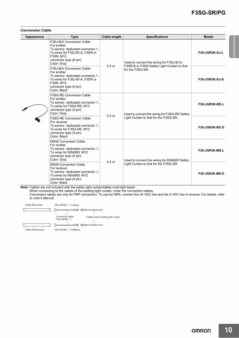
Conversion Cable
Note: Cables are not included with the safety light curtain/safety multi-light beam.When connecting to the cables of the existing light curtain, order the conversion cables.Conversion cables are only for PNP connection. To use for NPN, connect the 24 VDC line and the 0 VDC line in reverse. For details, refer to User's Manual.
Appearance Type Cable length Specifications ModelF3SJ-B/A Conversion CableFor emitterTo sensor: dedicated connector 1,To wires for F3SJ-B/-A, F3SR or F3SN: M12connector type (8 pin)Color: Gray
0.3 mUsed to convert the wiring for F3SJ-B/-A, F3SR-B or F3SN Safety Light Curtain to that for the F3SG-SR.
F39-JGR3K-SJ-L
F3SJ-B/A Conversion CableFor emitterTo sensor: dedicated connector 1,To wires for F3SJ-B/-A, F3SR or F3SN: M12connector type (8 pin)Color: Black
F39-JGR3K-SJ-D
F3SG-RE Conversion CableFor emitterTo sensor: dedicated connector 1,To wires for F3SG-RE: M12connector type (4 pin)Color: Gray
0.3 m Used to convert the wiring for F3SG-RE Safety Light Curtain to that for the F3SG-SR.
F39-JGR3K-RE-L
F3SG-RE Conversion CableFor receiverTo sensor: dedicated connector 1,To wires for F3SG-RE: M12connector type (4 pin)Color: Black
F39-JGR3K-RE-D
MS48 Conversion CableFor emitterTo sensor: dedicated connector 1,To wires for MS4800: M12connector type (5 pin)Color: Gray
0.3 m Used to convert the wiring for MS4800 Safety Light Curtain to that for the F3SG-SR.
F39-JGR3K-MS-L
MS48 Conversion CableFor receiverTo sensor: dedicated connector 1,To wires for MS4800: M12connector type (8 pin)Color: Black
F39-JGR3K-MS-D
F3SG-SR Emitter F39-JGR3K-@@-L(Gray)
F3SG-SR Receiver F39-JGR3K-@@-D(Black)
Conversion cableF39-JGR3K-@@
Cables of the existing light curtain
F3SG-SR/PG
11
Intelligent Tap and Configuration Tool SD Manager 3Intelligent Tap *
Note: Please contact your OMRON sales representative regarding the IO-Link setup file (IODD file).* Use the F39-SGBT Bluetooth® Communication Unit or a commercially available USB Type-CTM cable to connect to a PC.
Configuration tool SD Manager 3
Intelligent Tap-to-IO-Link Master Cable
* When the accessory is used, protect it from cutting oil.Note: Use the F39-JGA-D Extended Socket-Straight Cable or F39-JGB-D Extended Plug-Socket Cable for safety output (OSSD).
Appearance Type Specifications Model
Intelligent Tap
Used to configure the F3SG-SR/PG and connect external devices via IO-Link. The F3SG-SR/PG can be configured on a PC or with the DIP switch on the Intelligent Tap.IP67 and IP67G (JIS C 0920 Annex 1) rated when mated.
F39-SGIT-IL3
Bluetooth® Communication UnitMounted to the Intelligent Tap to connect with the SD Manager 3 via Bluetooth®.IP67 and IP67G (JIS C 0920 Annex 1) rated when mated.
F39-SGBT
Intelligent Tap Bracket For DIN in Panel Bracket to mount the Intelligent Tap on a DIN track. F39-LITF1
Type Specifications
SD Manager 3Configuration tool running on a PC.Use with the Intelligent Tap. (The Bluetooth® communication unit is required to connect using Bluetooth®.)For details, refer to your local Omron website.
SD Manager 3 Mobile APPMonitoring tool running on a smartphone and tablet.Use with the Intelligent Tap and Bluetooth® communication unit.For details, refer to your local Omron website.
Omron IO-Link master unit Type Cable length Specifications Model
*1. When the accessory is used, protect it from cutting oil.*2. Order the cable (root-plug cable for extended and extended cable) for emitter (end of model: -L) and the cable for receiver (end of model: -D).
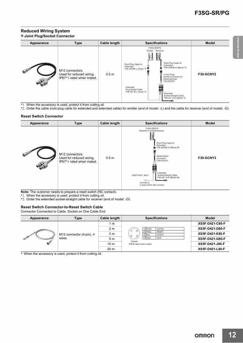
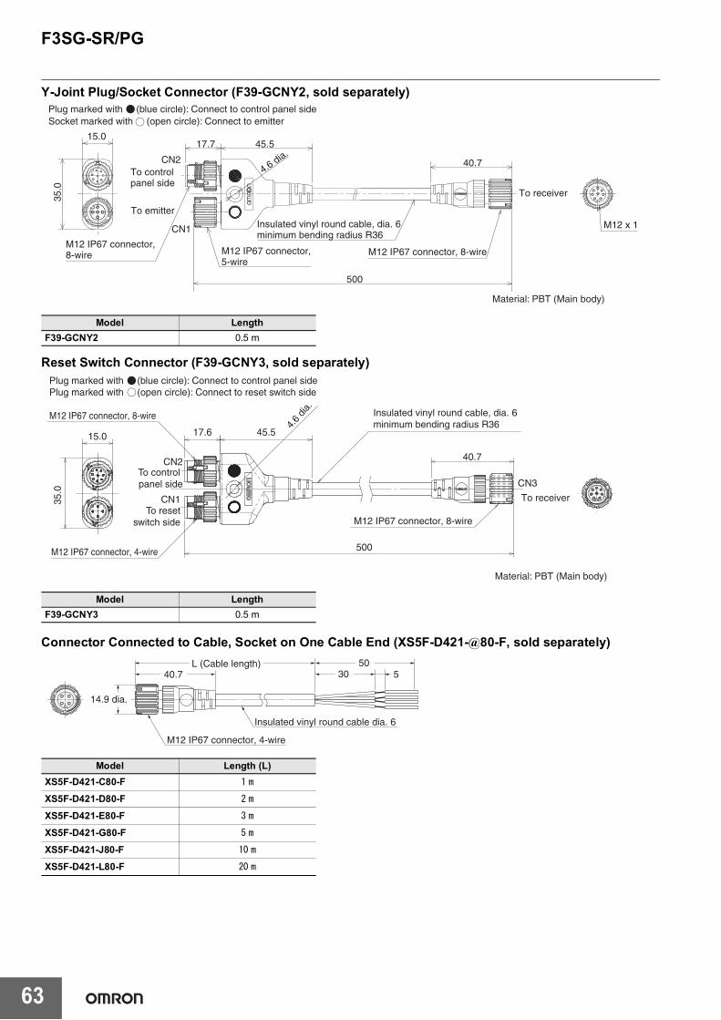
Reset Switch Connector
Note: The customer needs to prepare a reset switch (NC contact).*1. When the accessory is used, protect it from cutting oil.*2. Order the extended socket-straight cable for receiver (end of model: -D).
Reset Switch Connector-to-Reset Switch CableConnector Connected to Cable, Socket on One Cable End
* When the accessory is used, protect it from cutting oil.
Appearance Type Cable length Specifications Model
M12 connectors.Used for reduced wiring.IP67*1 rated when mated.
0.5 m F39-GCNY2
Appearance Type Cable length Specifications Model
M12 connectors.Used for reduced wiring.IP67*1 rated when mated.
0.5 m F39-GCNY3
Appearance Type Cable length Specifications Model
M12 connector (4-pin), 4 wires
1 m XS5F-D421-C80-F2 m XS5F-D421-D80-F3 m XS5F-D421-E80-F5 m XS5F-D421-G80-F
Root-Plug Cable for ExtendedF39-JGR3K-D (Black) *2
F3SG-SR/PGReceiver or emitter/receiver
Connect to a reset switch (NC contact)
Brown
White
Blue
Black
24V/0V
RESET
0V/24V
AUX
1
2
3
4
FemaleIP67* rated when mated.
3
21
4
F3SG-SR/PG
13
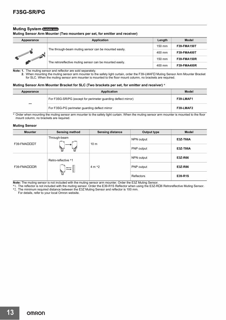
Muting SystemMuting Sensor Arm Mounter (Two mounters per set, for emitter and receiver)
Note: 1. The muting sensor and reflector are sold separately.2. When mounting the muting sensor arm mounter to the safety light curtain, order the F39-LMAF Muting Sensor Arm Mounter Bracket
for SLC. When the muting sensor arm mounter is mounted to the floor mount column, no brackets are required.
Muting Sensor Arm Mounter Bracket for SLC (Two brackets per set, for emitter and receiver) *
* Order when mounting the muting sensor arm mounter to the safety light curtain. When the muting sensor arm mounter is mounted to the floor mount column, no brackets are required.
Muting Sensor
Note: The muting sensor is not included with the muting sensor arm mounter. Order the E3Z Muting Sensor.*1. The reflector is not included with the muting sensor. Order the E39-R1S Reflector when using the E3Z-R6 Retroreflective Muting Sensor.*2. The minimum required distance between the E3Z Muting Sensor and reflector is 100 mm.
For details, refer to your local Omron website.
Appearance Application Length Model
The through-beam muting sensor can be mounted easily.150 mm F39-FMA150T
400 mm F39-FMA400T
The retroreflective muting sensor can be mounted easily.150 mm F39-FMA150R
400 mm F39-FMA400R
Appearance Application Model
---For F3SG-SR/PG (except for perimeter guarding deflect mirror) F39-LMAF1
For F3SG-PG perimeter guarding deflect mirror F39-LMAF2
Mounter Sensing method Sensing distance Output type Model
F39-FMAT
Through-beam
10 mNPN output E3Z-T66A
PNP output E3Z-T86A
F39-FMAR
Retro-reflective *1
4 m *2
NPN output E3Z-R66
PNP output E3Z-R86
Reflectors E39-R1S
Available soon
F3SG-SR/PG
14
Orde
ring
Info
rmat
ion
Muting Sensor Connection Box
* When the accessory is used, protect it from cutting oil.Note: 1. Select the same output type for both the safety light curtain/safety multi-light beam (PNP/NPN selection by wiring) and muting sensor
(PNP or NPN model).2. For details of the XS3W and XS5W, refer to your local OMRON website.3. Use the F39-JGB-D Extended Plug-Socket Cable to connect the muting sensor connection box with the Intelligent Tap.
The connection example for optical synchronization is shown below.
Appearance Application Specifications Cable Length Model
Up to 0880 0580 990 mm F39-ST0990Up to 1280 0880, 0980 1,310 mm F39-ST1310Up to 1520 1280 1,630 mm F39-ST1630Up to 1840 --- 1,950 mm F39-ST1950Up to 2080 --- 2,270 mm F39-ST2270
Appearance Protective height of safety light curtain Column height ModelUp to 0800 990 mm F39-SML0990Up to 1120 1,310 mm F39-SML1310Up to 1440 1,630 mm F39-SML1630Up to 1760 1,950 mm F39-SML1950Up to 2080 2,270 mm F39-SML2270
Appearance Safety Multi-Light Beam Column height ModelF3SG-4PG0580-2 990 mm F39-PML0990-2F3SG-4PG0880-3A/3L
1,310 mmF39-PML1310-3
F3SG-4PG0980-4 F39-PML1310-4
F3SG-4PG1280-4 1,630 mm F39-PML1630-4
Appearance Application Model
Mounted to the floor mount column or mirror column.The angle and height of the column can be adjusted. F39-STB
Available soon
F3SG-SR/PG
16
Orde
ring
Info
rmat
ion
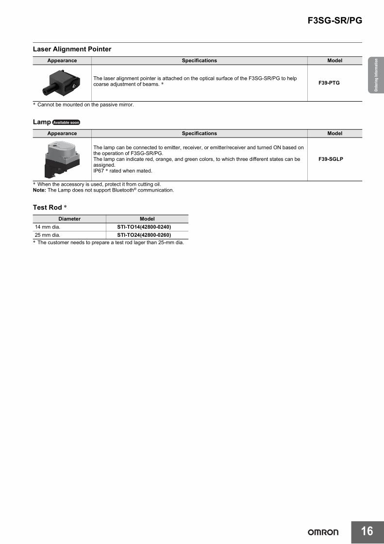
Laser Alignment Pointer
* Cannot be mounted on the passive mirror.
Lamp
* When the accessory is used, protect it from cutting oil.Note: The Lamp does not support Bluetooth® communication.
Test Rod *
* The customer needs to prepare a test rod lager than 25-mm dia.
Appearance Specifications Model
The laser alignment pointer is attached on the optical surface of the F3SG-SR/PG to help coarse adjustment of beams. * F39-PTG
Appearance Specifications Model
The lamp can be connected to emitter, receiver, or emitter/receiver and turned ON based on the operation of F3SG-SR/PG.The lamp can indicate red, orange, and green colors, to which three different states can be assigned.IP67 * rated when mated.
F39-SGLP
Diameter Model14 mm dia. STI-TO14(42800-0240)25 mm dia. STI-TO24(42800-0260)
Available soon
F3SG-SR/PG
17
Spatter Protection Cover (2 covers per set, one for emitter and one for receiver)
Note: 1. The operating range of the safety light curtain attached with the spatter protection cover is 10% shorter than the rating.2. Two or more spatter protection covers can be attached to the safety light curtain with a protective height not listed above.
The F39-HSG0360 is also available for use together with other spatter protection covers.
AppearanceSafety light curtain
ModelFinger protection Hand protection Arm/leg protection
Beam gap 10 mm 20 mm 40 mm 80 mmNumber of beams 15 to 199 8 to 124 6 to 38 4 to 12Lens size 4.4 3.4 mm (W H) 6.7 4.5 mm (W H)Protective height 160 to 2,000 mm 160 to 2,480 mm 240 to 1,520 mm 280 to 920 mm
Operating range
Long 0.3 to 10.0 m * 0.3 to 20.0 mShort 0.3 to 3.0 m * 0.3 to 7.0 m* When operating at an ambient temperature of -10 to -30°C, use the F3SG-SR with the operating range of 0.3 to 5.0 m in Long
Mode and 0.3 to 1.5 m in Short Mode.
Response time*1
Normal mode
ON to OFF
Optical synchronization: 8 to 18 msWired synchronization: 10 to 21 ms
Optical synchronization: 8 to 13 msWired synchronization: 10 to 17 ms
Optical synchronization: 8 msWired synchronization: 10 ms
OFF to ON
Optical synchronization: 40 to 90 msWired synchronization: 50 to 105 ms
Optical synchronization: 40 to 65 msWired synchronization: 50 to 85 ms
Optical synchronization: 40 msWired synchronization: 50 ms
×2 Slow mode *2
ON to OFF
Optical synchronization: 16 to 36 msWired synchronization: 20 to 42 ms
Optical synchronization: 16 to 26 msWired synchronization: 20 to 34 ms
Optical synchronization: 16 msWired synchronization: 20 ms
OFF to ON
Optical synchronization: 80 to 180 msWired synchronization: 100 to 210 ms
Optical synchronization: 80 to 130 msWired synchronization: 100 to 170 ms
Optical synchronization: 80 msWired synchronization: 100 ms
×4 Slow mode *2
ON to OFF
Optical synchronization: 32 to 72 msWired synchronization: 40 to 84 ms
Optical synchronization: 32 to 52 msWired synchronization: 40 to 68 ms
Optical synchronization: 32 msWired synchronization: 40 ms
OFF to ON
Optical synchronization: 160 to 360 msWired synchronization: 200 to 420 ms
Optical synchronization: 160 to 260 msWired synchronization: 200 to 340 ms
Optical synchronization: 160 msWired synchronization: 200 ms
×8 Slow mode *2
ON to OFF
Optical synchronization: 64 to 144 msWired synchronization: 80 to 168 ms
Optical synchronization: 64 to 104 msWired synchronization: 80 to 136 ms
Optical synchronization: 64 msWired synchronization: 80 ms
OFF to ON
Optical synchronization: 320 to 720 msWired synchronization: 400 to 840 ms
Optical synchronization: 320 to 520 msWired synchronization: 400 to 680 ms
Optical synchronization: 320 msWired synchronization: 400 ms
*1. Response time when used in one segment system. Refer to page 24. Refer to the User's Manual for cascaded connection.
Type 4 ±2.5° max. ** Emitter and receiver at operating range of 3 m or greater.
Light source Infrared LEDs, Wavelength: 870 nmStartup waiting time 3 s max.
Electrical
Power supply voltage (Vs) SELV/PELV 24 VDC±20% (ripple p-p 10% max.)Current consumption Refer to page 24
Safety outputs (OSSD)
Two PNP or NPN transistor outputs (PNP or NPN is selectable by wiring of power supply.)Load current: 300 mA max., Residual voltage: 2 V max. (except for voltage drop due to cable extension), Capacitive load: 1 F max., Inductive load: 2.2 H max. *1*2*3Leakage current: 1 mA max.(PNP), 2 mA max.(NPN) *4
*1. For the F3SG-SRA, the load current is 150 mA max. in 2-segment cascade and 80 mA max. in 3-segment cascade.
*2. The residual voltage is 3 V max. when the Intelligent Tap is connected to the sensor.*3. The load inductance is the maximum value when the safety output frequently repeats ON and OFF.
When you use the safety output at 4 Hz or less, the usable load inductance becomes larger.*4. These values must be taken into consideration when connecting elements including a capacitive load
such as a capacitor.
Auxiliary outputOne PNP or NPN transistor output (PNP or NPN is selectable by wiring of power supply.)Load current: 100 mA max., Residual voltage: 2 V max. ** The residual voltage is 3 V max. when the Intelligent Tap is connected to the sensor.
Output operation mode
Safety output Light-ON (Safety outputs are turned to the ON state when the receiver receives an emitting signal.)Auxiliary output Safety output (Inverted signal output: Enable) (default) (Configurable by SD Manager 3)
F3SG-SR/PG
19
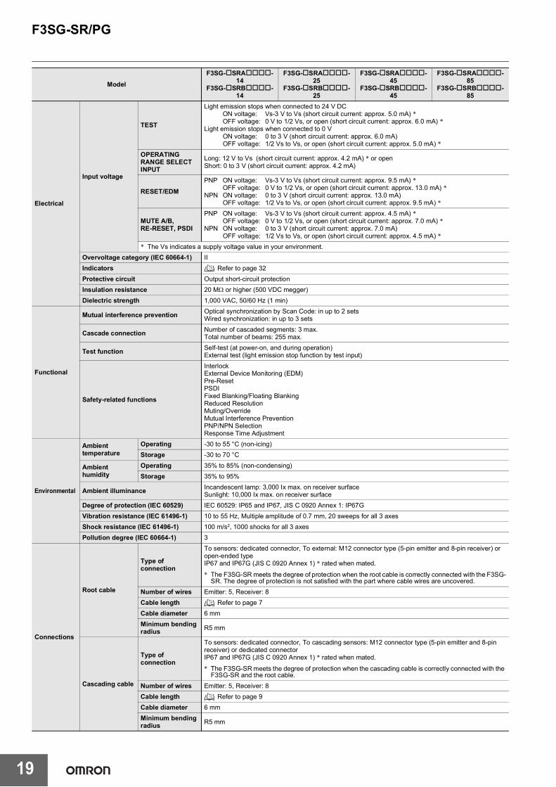
Electrical
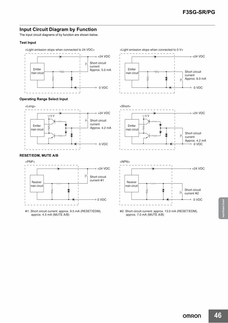
Input voltage
TEST
Light emission stops when connected to 24 V DCON voltage: Vs-3 V to Vs (short circuit current: approx. 5.0 mA) *OFF voltage: 0 V to 1/2 Vs, or open (short circuit current: approx. 6.0 mA) *
Light emission stops when connected to 0 VON voltage: 0 to 3 V (short circuit current: approx. 6.0 mA)OFF voltage: 1/2 Vs to Vs, or open (short circuit current: approx. 5.0 mA) *
OPERATING RANGE SELECT INPUT
Long: 12 V to Vs (short circuit current: approx. 4.2 mA) * or openShort: 0 to 3 V (short circuit current: approx. 4.2 mA)
RESET/EDMPNP ON voltage: Vs-3 V to Vs (short circuit current: approx. 9.5 mA) *
OFF voltage: 0 V to 1/2 Vs, or open (short circuit current: approx. 13.0 mA) *NPN ON voltage: 0 to 3 V (short circuit current: approx. 13.0 mA)
OFF voltage: 1/2 Vs to Vs, or open (short circuit current: approx. 9.5 mA) *
MUTE A/B, RE-RESET, PSDI
PNP ON voltage: Vs-3 V to Vs (short circuit current: approx. 4.5 mA) *OFF voltage: 0 V to 1/2 Vs, or open (short circuit current: approx. 7.0 mA) *
NPN ON voltage: 0 to 3 V (short circuit current: approx. 7.0 mA)OFF voltage: 1/2 Vs to Vs, or open (short circuit current: approx. 4.5 mA) *
* The Vs indicates a supply voltage value in your environment.Overvoltage category (IEC 60664-1) IIIndicators Refer to page 32Protective circuit Output short-circuit protectionInsulation resistance 20 M or higher (500 VDC megger)Dielectric strength 1,000 VAC, 50/60 Hz (1 min)
Functional
Mutual interference prevention Optical synchronization by Scan Code: in up to 2 setsWired synchronization: in up to 3 sets
Cascade connection Number of cascaded segments: 3 max.Total number of beams: 255 max.
Test function Self-test (at power-on, and during operation)External test (light emission stop function by test input)
Operating -30 to 55 °C (non-icing)Storage -30 to 70 °C
Ambient humidity
Operating 35% to 85% (non-condensing)Storage 35% to 95%
Ambient illuminance Incandescent lamp: 3,000 Ix max. on receiver surfaceSunlight: 10,000 Ix max. on receiver surface
Degree of protection (IEC 60529) IEC 60529: IP65 and IP67, JIS C 0920 Annex 1: IP67GVibration resistance (IEC 61496-1) 10 to 55 Hz, Multiple amplitude of 0.7 mm, 20 sweeps for all 3 axesShock resistance (IEC 61496-1) 100 m/s2, 1000 shocks for all 3 axesPollution degree (IEC 60664-1) 3
Connections
Root cable
Type of connection
To sensors: dedicated connector, To external: M12 connector type (5-pin emitter and 8-pin receiver) or open-ended typeIP67 and IP67G (JIS C 0920 Annex 1) * rated when mated.
* The F3SG-SR meets the degree of protection when the root cable is correctly connected with the F3SG-SR. The degree of protection is not satisfied with the part where cable wires are uncovered.
Number of wires Emitter: 5, Receiver: 8Cable length Refer to page 7Cable diameter 6 mmMinimum bending radius R5 mm
Cascading cable
Type of connection
To sensors: dedicated connector, To cascading sensors: M12 connector type (5-pin emitter and 8-pin receiver) or dedicated connectorIP67 and IP67G (JIS C 0920 Annex 1) * rated when mated.
* The F3SG-SR meets the degree of protection when the cascading cable is correctly connected with the F3SG-SR and the root cable.
Number of wires Emitter: 5, Receiver: 8Cable length Refer to page 9Cable diameter 6 mmMinimum bending radius R5 mm
ModelF3SG-SRA-
14F3SG-SRB-
14
F3SG-SRA-25
F3SG-SRB-25
F3SG-SRA-45
F3SG-SRB-45
F3SG-SRA-85
F3SG-SRB-85
F3SG-SR/PG
20
Ratin
gs a
nd S
peci
ficat
ions
Connections
Extension cable- Extended
Socket-Straight Cable
- Extended Plug-Socket Cable
Type of connection
M12 connector type (5-pin emitter and 8-pin receiver), IP67 * rated when mated* The extension cable meets the degree of protection when the root cable is correctly connected with the
extension cable. The degree of protection is not satisfied with the part where cable wires are uncovered.Number of wires Emitter: 5, Receiver: 8Cable length Refer to page 8Cable diameter 6.6 mmMinimum bending radius R36 mm
Cable extension
Refer to page 21 for restrictions on cable extension.
Root cable
In optical synchronization: 100 m max. * between power supply and emitter and between power supply and receiverIn wired synchronization: 100 m max. * between power supply and emitter, between power supply and receiver, and between emitter and receiver
* When the Intelligent Tap (F39-SGIT-IL3) is connected to the sensor, this applies in the case of the rated power supply of 24 VDC to 24 VDC +20%.
Cascade connection
Extension cable between sensors: 10 m max. (not including Cascading Cable for Extended *1 and Root Cable *2.)
Instruction Sheet, Quick Installation Manual, Troubleshooting Guide Sticker, Warning Zone Label, End Cap (for switching Scan Code Selection function), Side-Mount Bracket (Intermediate Bracket) (F39-LSGF) *
* The quantity varies depending on the protective height.Protective height of 0160 to 1440: 2 sets (total 4 pcs), 1520 to 2480: 3 sets (total 6 pcs)
Conformity
Conforming standards Refer to page 31Type of ESPE (IEC 61496-1) F3SG-4SR-: Type 4Performance Level (PL)/Safety category F3SG-4SR-: PL e/Category 4 (EN ISO 13849-1:2015)
PFHD F3SG-SR-: 1.1×10⁻⁸ max. (IEC 61508)Proof test interval TM Every 20 years (IEC 61508)SFF 99% (IEC 61508)HFT 1 (IEC 61508)Classification Type B (IEC 61508-2)
ModelF3SG-SRA-
14F3SG-SRB-
14
F3SG-SRA-25
F3SG-SRB-25
F3SG-SRA-45
F3SG-SRB-45
F3SG-SRA-85
F3SG-SRB-85
F3SG-SR/PG
21
Restrictions on cable extensionFor the cable extension of the F3SG-SR, refer to the following diagrams. For the cable extension of the F3SG-SR with the Intelligent Tap, refer to User's Manual.
- Wired synchronization
* Not including Cascading Cable for Extended (F39-JGR3W) and Root Cable (F39-JGR3K).
- Optical synchronization
Emitter
Receiver
Maximum extension length
(1) to (4): 10 m each *(5) to (6): 100 m each
(1)
(2)
(3)
(4)
(5)
(6)
Emitter
Receiver
(1)
(2)
(3)
(4)
(5)
(6)
Maximum extension length
(1) to (4): 10 m each *(5) to (6): 100 m each
Powersupply
Powersupply
Powersupply
F3SG-SR/PG
22
Ratin
gs a
nd S
peci
ficat
ions
Intelligent Tap F39-SGIT-IL3Model F39-SGIT-IL3
Applicable sensor F3SG-SR Series
PerformanceResponse time
Output ON to OFF and OFF to ON: 44 ms max. each *
* The response time is the time interval between the changes of the states of the sensor OSSD's and the DO (pin 2).Startup waiting time 3 s max.
Electrical
Power supply voltage (Vs) Supplied from external power source: SELV/PELV 24 VDC±20% (ripple p-p 10% max.)USB bus powered: 5 VDC
Current consumption 85 mA max. (When connecting 24 VDC power supply and IO-Link Master)Safety outputs (OSSD)/Auxiliary output
Refer to the ratings and specifications of the F3SG-SR. The safety outputs and auxiliary output of the Intelligent Tap are directly connected to those of the F3SG-SR.
Digital output for pin 2 (IO-Link) *
One PNP transistor outputLoad current: 100 mA max., Residual voltage: 2 V max., Leakage current: 1 mA max.The DO is in the OFF state when the safety outputs are in the ON state. The DO is in the ON state when the safety outputs are in the OFF state. (Regardless of the PNP/NPN setting of the F3SG-SR)
* For the DO (pin 2) of CN3
Input voltage
RESET, EDM
PNPON voltage: Vs-3 V to Vs (short circuit current: approx. 9.5 mA) *2OFF voltage: 0 V to 1/2 Vs, or open (short circuit current: approx. 13.0 mA) *2
NPNON voltage: 0 to 3 V (short circuit current: approx. 13.0 mA)OFF voltage: 1/2 Vs to Vs, or open (short circuit current: approx. 9.5 mA) *2
MUTE A/B,PRE-RESET, PSDI *1
PNPON voltage: Vs-3 V to Vs (short circuit current: approx. 4.5 mA) *2OFF voltage: 0 V to 1/2 Vs, or open (short circuit current: approx. 7.0 mA) *2
NPNON voltage: 0 to 3 V (short circuit current: approx. 7.0 mA)OFF voltage: 1/2 Vs to Vs, or open (short circuit current: approx. 4.5 mA) *2
*1. PSDI is only available for F3SG-SR. *2. The Vs indicates a supply voltage value in your environment.
Functional Maintenance Information Error LogPower-ON Time
Environmental
Ambient temperature
Operating -30 to 55 °C (non-icing)Storage -30 to 70 °C
Ambient humidity
Operating 35% to 85% (non-condensing)Storage 35% to 85%
Degree of protection (IEC 60529) IP65, IP67 and IP67G (Covers and cables connected with the Intelligent Tap.)Vibration resistance (IEC 61496-1) 10 to 55 Hz, Multiple amplitude of 0.7 mm, 20 sweeps for all 3 axesShock resistance (IEC 61496-1) 100 m/s2, 1000 shocks for all 3 axesPollution degree (IEC 60664-1) 3
Connections
To sensors, control box and IO-Link
M12 connectors: 8-pin (CN1: receiver and CN2: control box) and 5-pin (CN3: IO-Link and CN4: emitter), IP67 and IP67G (JIS C 0920 Annex 1) * rated when mated.
* The F3SG-SR meets the degree of protection when the root cable of the F3SG-SR is correctly connected with the F3SG-SR.
Connection USB Type-C
Cable extension
20 m max. between IO-Link Master and Intelligent Tap, 4 m max.* between PC and Intelligent Tap via USB cable
* It is not guaranteed that the Intelligent Tap is connectable to any PC or USB cable. Verify the connection with the USB cable you use.
IO-Link communications
IO-Link version Version 1.1Baud rate COM3: 230.4 kbpsData length PD: 4 bytes, OD: 32 bytes (M-sequence type: TYPE_2_V)Minimum cycle time 12 ms
Material PBT resinWeight F39-SGIT-IL3: 180 g (when packaged), F39-LITF1: 50 g (when packaged)
Included accessories Instruction Sheet and M12 Connector Cover (2 pcs)
F3SG-SR/PG
23
Bluetooth® Communication Unit
* It depends on use environment conditions.
Model F39-SGBTApplicable sensor F3SG-SR SeriesPower supply voltage (Vs) 24 VDC±20%, ripple p-p 10% max. (shares power supply of Intelligent Tap)Current consumption 30 mA max. (shares power supply of Intelligent Tap)
Ambient temperature Operating: -30 to 55 °C (non-icing)Storage: -30 to 70 °C
Ambient humidity Operating: 35% to 85% (non-condensing)Storage: 35% to 85%
Degree of protection IP65, IP67 and IP67G (rated when connected to Intelligent Tap)Vibration resistance 10 to 55 Hz, Multiple amplitude of 0.7 mm, 20 sweeps for all 3 axesShock resistance 100m/s2, 1000 shocks for all 3 axesType of connection To be connected to Intelligent TapCommunication system Bluetooth® Version 3.0Communication profile SPP (Serial Port Profile)Transmission distance Approx. 10 m max. (Output power: Class 2) *Material PBT resinWeight 70 g (when packaged)
F3SG-SR/PG
24
Ratin
gs a
nd S
peci
ficat
ions
List o
f Mod
els/R
espo
nse T
ime/
Curre
nt C
onsu
mpt
ion/
Wei
ght
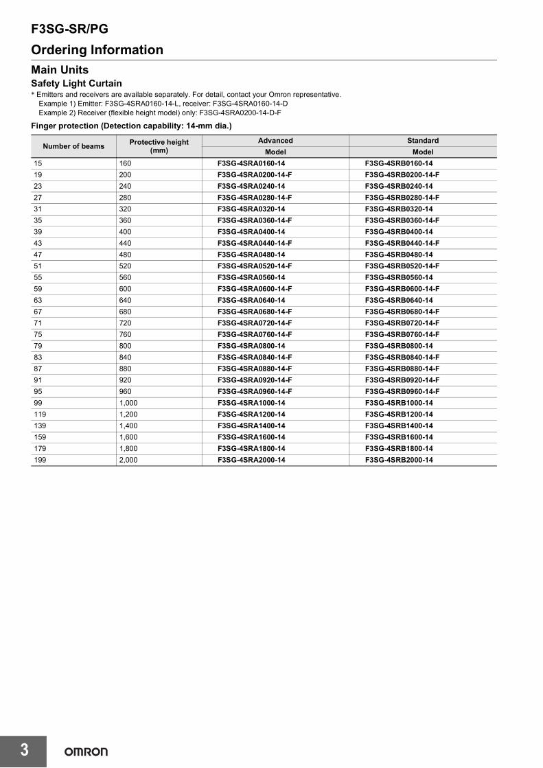
List of Models/Response Time/Current Consumption/WeightF3SG-SRFinger protection (Detection capability: 14-mm dia.)List of Models and Response Times
Note: 1. The maximum speed of movement of a test rod up to which the detection capability is maintained is 2.0 m/s.2. The response times of “Optical synchronization” are values when Scan Code is set at Code B. The response times for Code A are 1 ms
Note: 1. The net weight is the weight of an emitter and a receiver per set.2. The gross weight is the weight of an emitter, a receiver, included accessories and a package.
Model Number of beams Protective height [mm]
Current consumption [mA] Weight [kg]Emitter Receiver Net Gross
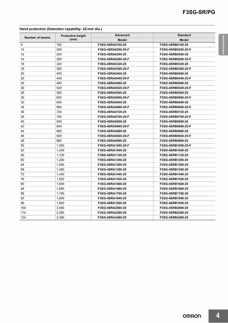
Hand protection (Detection capability: 25-mm dia.)List of Models and Response Times
Note: 1. The maximum speed of movement of a test rod up to which the detection capability is maintained is 2.0 m/s.2. The response times of "Optical synchronization" are values when Scan Code is set at Code B. The response times for Code A are 1 ms
Note: 1. The net weight is the weight of an emitter and a receiver per set.2. The gross weight is the weight of an emitter, a receiver, included accessories and a package.
Current consumption [mA] Weight [kg]Emitter Receiver Net Gross
F3SG-SR/PG
29
Arm/leg protection (Detection capability: 45-mm dia.)List of Models and Response Times
Note: 1. The maximum speed of movement of a test rod up to which the detection capability is maintained is 2.0 m/s.2. The response times of "Optical synchronization" are values when Scan Code is set at Code B. The response times for Code A are 1 ms
shorter than these values.
List of Models, Current Consumption and Weight
Note: 1. The net weight is the weight of an emitter and a receiver per set.2. The gross weight is the weight of an emitter, a receiver, included accessories and a package.
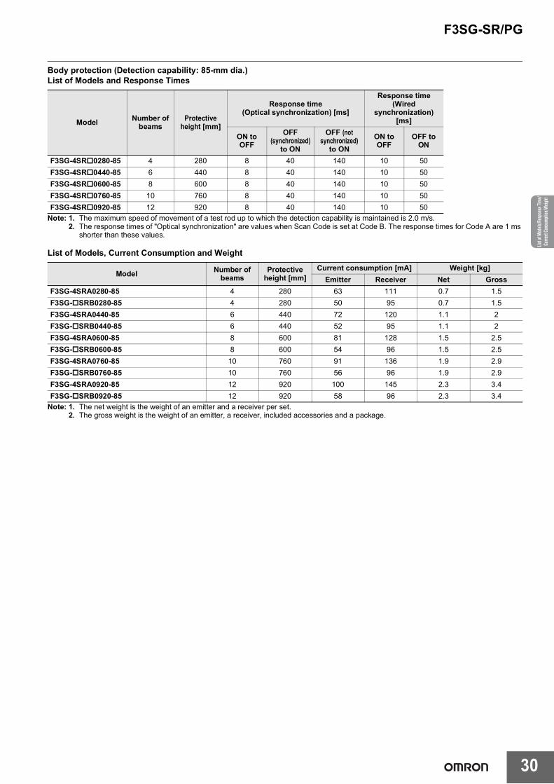
Body protection (Detection capability: 85-mm dia.)List of Models and Response Times
Note: 1. The maximum speed of movement of a test rod up to which the detection capability is maintained is 2.0 m/s.2. The response times of "Optical synchronization" are values when Scan Code is set at Code B. The response times for Code A are 1 ms
shorter than these values.
List of Models, Current Consumption and Weight
Note: 1. The net weight is the weight of an emitter and a receiver per set.2. The gross weight is the weight of an emitter, a receiver, included accessories and a package.
Legislation and Standards1. The F3SG-SR does not receive type approval provided by Article 44-2 of the Industrial Safety and Health Act of Japan. When using the F3SG-SR in Japan
as a "safety system for pressing or shearing machines" prescribed in Article 42 of that law, the machine control system must receive type approval. 2. The F3SG-SR is electro-sensitive protective equipment (ESPE) in accordance with European Union (EU) Machinery Directive Index Annex V, Item 2. 3. EU Declaration of Conformity
OMRON declares that the F3SG-SR is in conformity with the requirements of the following EU Directives: Machinery Directive 2006/42/EC EMC Directive 2014/30/EU
4. Conforming Standards(1) European standards
EN61496-1 (Type 4 and Type 2 ESPE), EN 61496-2 (Type 4 and Type 2 AOPD), EN61508-1 through -4 (SIL 3 for Type 4 and SIL 1 for Type 2), EN ISO 13849-1:2015 (PL e, Category 4 for Type 4 and PL c, Category 2 for Type 2)
(2) International standardsIEC61496-1 (Type 4 and Type 2 ESPE), IEC61496-2 (Type 4 and Type 2 AOPD), IEC61508-1 through -4 (SIL 3 for Type 4 and SIL 1 for Type 2), ISO 13849-1:2015 (PL e, Category 4 for Type 4 and PL c, Category 2 for Type 2)
(3) JIS standardsJIS B 9704-1 (Type 4 and Type 2 ESPE), JIS B 9704-2 (Type 4 and Type 2 AOPD)
(4) North American standardsUL61496-1 (Type 4 and Type 2 ESPE), UL61496-2 (Type 4 and Type 2 AOPD), UL508, UL1998, CAN/CSA C22.2 No.14, CAN/CSA C22.2 No.0.8
(5) Chinese standardsGB/T 4584 (Specification of active opto-electronic protective devices for presses)(Models: F3SG-4SR-14/-25 in the case of the ON to OFF response time not exceeding 20 ms max.)The following configurations of the F3SG-SR are compliant with GB/T 4584.Configurations using the F3SG-SR with detection capability of 14-mm or 25-mm dia. and 20 ms max. of the ON to OFF response time
* Refer to User's Manual for more information on the response time for the F3SG-SR in cascade connection.Note: The F3SG-SR's with detection capability of 45-mm and 85-mm dia. are not compliant with GB/T 4584. Refer to Ratings and
Specifications on page 18 for more information on the ratings and specifications by model.5. Third-Party Certifications
(1) TÜV SÜD• EC Type-Examination certificate:
EU Machinery Directive, Type 4 and Type 2 ESPE (EN61496-1), Type 4 and Type 2 AOPD (EN 61496-2)• Certificate:
Type 4 and Type 2 ESPE (EN61496-1), Type 4 and Type 2 AOPD (EN61496-2), EN 61508-1 through -4 (SIL 3 for Type 4 and SIL 1 for Type 2), EN ISO 13849-1:2015 (PL e, Category 4 for Type 4, and PL c, Category 2 for Type 2)
(2) UL• UL Listing:
Type 4 and Type 2 ESPE (UL61496-1), Type 4 and Type 2 AOPD (UL61496-2), UL508, UL1998, CAN/CSA C22.2 No.14, CAN/CSA C22.2 No.0.8(3) China National Casting and Forging Machines Quality Supervision and Inspection Center
• Certificate:GB/T 4584 (Specification of active opto-electronic protective devices for presses)(Models: F3SG-4SR-14/-25 in the case of the ON to OFF response time not exceeding 20 ms max.)
6. Other Standards The F3SG-SR/PG is designed according to the standards listed below. To make sure that the final system complies with the following standards and regulations, you are asked to design and use it in accordance with all other related standards, laws, and regulations. If you have any questions, consult with specialized organizations such as the body responsible for prescribing and/or enforcing machinery safety regulations in the location where the equipment is to be used. • European Standards: EN415-4, EN691-1, EN692, EN693, IEC 62046• U.S. Occupational Safety and Health Standards: OSHA 29 CFR 1910.212• U.S. Occupational Safety and Health Standards: OSHA 29 CFR 1910.217• American National Standards: ANSI B11.1 to B11.19• American National Standards: ANSI/RIA R15.06• Canadian Standards Association CSA Z142, Z432, Z434• SEMI Standards SEMI S2• Japan Ministry of Health, Labour and Welfare "Guidelines for Comprehensive Safety Standards of Machinery", Standard Bureau's
Notification No. 0731001 dated July 31, 2007.rms and Conditions Agreement• Chinese National Standards: GB17120, GB27607
7. Meaning of mark according to EU WEEE DirectiveDispose in accordance with applicable regulations.
8. Regions where F39-SGBT can be used For the regions where the F39-SGBT can be used, refer to the following instruction manuals of the F39-SGBT.
Detection capability Protective height Number of beams Configuration Synchronization
methodResponse Time
AdjustmentON to OFF
response time14-mm dia. 160 to 2000 mm - Single Optical Normal 18 ms max.14-mm dia. 160 to 1400 mm - Single Wired Normal 17 ms max.25-mm dia. 160 to 2480 mm - Single Optical/Wired Normal 17 ms max.Combination of 14-mm 25-mm dia. In cascade connection - 255 max. Cascaded Optical Normal 18 ms max. *
Combination of 14-mm 25-mm dia. In cascade connection - 140 max. Cascaded Wired Normal 15 ms max. *
Document Title No.F39-SGBT Instruction Sheet 4615743-0F39-SGBT Regulations and Standards 4615744-8
F3SG-SR/PG
32
Legi
slat
ion
and
Sta
ndar
dsIn
dica
tor
IndicatorLED Indicators on F3SG-SRShown below are indication statuses of the LED indicators on the F3SG-SR when you purchased.
Emitter (F3SG-SR)
*1. The indicator of the emitter is illuminated only in the case the Wired Synchronization is enabled and is off in the case the Optical Synchronization is enabled.
*2. Configurable by SD Manager 3.*3. This is the case for the Standard Muting mode. For other muting modes, refer to User's Manual.*4. The Area Beam Indicator closer to the "TOP" mark on the F3SG-SR blinks.*5. The Area Beam Indicator closer to the "BTM" mark on the F3SG-SR blinks.*6. DIP switches is on the Intelligent Tap.
Location Indicator Name Color Illuminated Blinking F3SG-SRA F3SG-SRB
1 Scan code
Green Code A is selected
--- X XOrange Code B is selected
OFFAutomatic interference prevention by wired synchronization being performed
2 Lockout Red
LOCKOUT state. The indicator is illuminated in the emitter of another sensor segment than that having a lockout error (when in cascade connection or between the emitter and receiver in the Wired Synchronization)
LOCKOUT state. The indicator is illuminated in the emitter of a sensor segment having a lockout error
X X
3 Operating range
Green Long Mode is selectedLOCKOUT state due to Operating range selection setting error X X
OFF Short Mode is selected
4 Test Yellow --- External Test is being performed X X
5 ---Area Beam Indicator (ABI) (*1)
GreenThe target beams of the ABI are unblocked and the safety outputs are turned ON
MUTING or OVERRIDE state. In the MUTING state, only the ABI indicators in the muting zone are blinking. Or the target beams of the ABI are blocked instantaneously
X ---
Orange
Incident light level of the target beams of the ABI is 170% (factory default setting (*2)) or less of ON-threshold (for 5 to 10 s)
Incident light level of the target beams of the ABI is 170% (factory default setting (*2)) or less of ON threshold5 to 10 s after illuminated when incident light level of the target beams of the ABI is 170% (factory default setting (*2)) or less of ON threshold. Or one muting input becomes the ON state and the MUTING state has not been started yet, or one muting input becomes the OFF state and the other is not in the OFF state yet. (*3)
Red The target beams of the ABI are blocked
LOCKOUT state due to Cap error or Other sensor error (*4), or Lockout state due to DIP Switch setting error (*5 *6)
OFF
The target beams of the ABI are unblocked (The ABI then will be illuminated in green when the safety outputs are turned ON.)
---
6 TOP Top-beam-state (*1) Blue The top beam is unblocked
MUTING/OVERRIDE state, or LOCKOUT state due to Cap error or Other sensor error
--- X
7 BTM Bottom-beam-state (*1) Blue The bottom beam is unblocked
MUTING/OVERRIDE, or LOCKOUT state due to DIP Switch setting error (*6)
--- X
CODE
C
or
ERR
E
or
LONG
L
or
TEST
T
or
F3SG-SR/PG
33
Receiver (F3SG-SR)
*1. Refer to Troubleshooting on page 64 for more information on blinking patterns.*2. Configurable by SD Manager 3.*3. This is the case for the Standard Muting mode. For other muting modes, refer to User's Manual.*4. The Area Beam Indicator closer to the "TOP" mark on the F3SG-SR blinks.*5. The Area Beam Indicator closer to the "BTM" mark on the F3SG-SR blinks.*6. DIP switches is on the Intelligent Tap.Note: In the SETTING state to make settings with the SD Manager 3, the TEST, LONG and CODE indicators on the emitter and the CFG, PNP
and CODE indicators on the receiver blink. (TEST: Yellow, LONG/CODE: Green, CFG/PNP/CODE: Green)For more information on the statuses of the LED indicators in the SETTING state, refer to User's Manual.
Location Indicator Name Color Illuminated Blinking F3SG-SRA F3SG-SRB
1 Scan code
Green Code A is selected
--- X XOrange Code B is selected
OFFAutomatic interference prevention by wired synchronization being performed
2 Lockout Red
LOCKOUT state. The indicator is illuminated in the receiver of another sensor segment than that having a lockout error (when in cascade connection or between the emitter and receiver in the Wired Synchronization)
LOCKOUT state. The indicator is illuminated in the receiver of a sensor segment having a lockout error
X X
3 ON/OFF
Green Safety outputs are in ON state --- X X
Red Safety outputs are in OFF stateLOCKOUT state due to Safety output error, or error due to abnormal power supply or noise
X X
4 Maintenance
Red
LOCKOUT state due to a recoverable error (When in cascade connection, the indicator of only the sensor segment having the error is illuminated)
LOCKOUT state due to a replacement-recommended error (When in cascade connection, the indicator of only the sensor segment having the error blinks)
X X
Orange
Safety outputs are instantaneously turned OFF due to ambient light, vibration or noise. Or sequence error in Muting, Pre-Reset or PSDI
Intelligent Tap is in the LOCKOUT state X X
5 PNP/NPN mode
Green PNP is configuredPolarity of PNP is changed to NPN, or vice versa, during operation, and internal circuit is defective
X X
OFF NPN is configured
6 Configuration Green
Fixed or Floating Blanking, Reduced Resolution, Warning Zone or Slow mode of Response Time Adjustment is enabled. Or after the Muting zone is determined by the Dynamic Muting function.
TEACH-IN mode, zone measurement being performed by Dynamic Muting, or LOCKOUT state due to Blanking monitoring error, Configuration error or Parameter error
X X
7 Sequence Yellow INTERLOCK state Sequence or sequence error in Muting, Pre-Reset or PSDI (*1) or Teach-in error X X
8 --- Area Beam Indicator (ABI)
GreenThe target beams of the ABI are unblocked and the safety outputs are turned ON
MUTING or OVERRIDE state. In the MUTING state, only the ABI indicators in the muting zone are blinking. Or the target beams of the ABI are blocked instantaneously
X ---Orange
Incident light level of the target beams of the ABI is 170% (factory default setting (*2)) or less of ON-threshold (for 5 to 10 s)
Incident light level of the target beams of the ABI is 170% (factory default setting (*2)) or less of ON threshold 5 to 10 s after illuminated when incident light level of the target beams of the ABI is 170% (factory default setting (*2)) or less of ON threshold. Or one muting input becomes the ON state and the MUTING state has not been started yet, or one muting input becomes the OFF state and the other is not in the OFF state yet. (*3)
Red The target beams of the ABI are blocked
LOCKOUT state due to Cap error or Other sensor error (*4), or LOCKOUT state due to DIP Switch setting error (*5*6)
OFF
The target beams of the ABI are unblocked (The ABI then will be illuminated in green when the safety outputs are turned ON.)
---
9 TOP Top-beam-state Blue The top beam is unblocked MUTING/OVERRIDE state, or LOCKOUT
state due to Cap error or Other sensor error --- X
10 BTM Bottom-beam-state Blue The bottom beam is unblocked MUTING/OVERRIDE state, or LOCKOUT
state due to DIP Switch setting error (*6) --- X
CODE
C
or
ERR
E
or
OSSD
O
or
MAINT
M
or
PNP
P
or
CFG
F
or
SEQ
S
or
F3SG-SR/PG
34
Indi
cato
r
LED Indicators on Intelligent TapShown below are indication statuses of LED indicators on the Intelligent Tap when you purchased.
*1. When the safety outputs of the F3SG-SR are in the ON state, the outputs of the Intelligent Tap are in the ON state.*2. When the safety outputs of the F3SG-SR are in the OFF state, the outputs of the Intelligent Tap are in the OFF state.Note: In the SETTING state to make settings with the SD Manager 3, the IN, OUT indicators blink. (IN: Yellow, OUT: Green)
For more information on the statuses of the LED indicators in the SETTING state, refer to User's Manual.
Location Indicator Name Color Illuminated Blinking
1 IN Sensor status Yellow Safety outputs of the F3SG-SR are in the ON state
The F3SG-SR is in the LOCKOUT state. Or the Intelligent Tap is waiting for Push Switch operation (in the Backup) or the Intelligent Tap and F3SG-SR are waiting for restart (in the Backup). Or communication error in the Backup or between the F3SG-SR and the Intelligent Tap. Or the Restoration failed
2 OUT Output statusGreen Outputs of the Intelligent Tap are in the ON
state(*1)
The Restoration failed. Or in the Restoration, the Intelligent Tap has communication error, is waiting for Push Switch operation or transferring data, or the Intelligent Tap and F3SG-SR are waiting for restart.
Red Outputs of the Intelligent Tap are in the OFF state (*2)
Communication error between the F3SG-SR and the Intelligent Tap
3 IO-Link IO-Link Green --- Intelligent Tap communicates with IO-Link Master. Or IO-Link circuit error
4 ERR Lockout Red
The Intelligent Tap is in the LOCKOUT state, or has communication error, DIP Switch circuit error at startup, communication error in the Backup or Restoration, restoration failure, IO-Link circuit error, power supply voltage error or other errors
---
F3SG-SR/PG
35
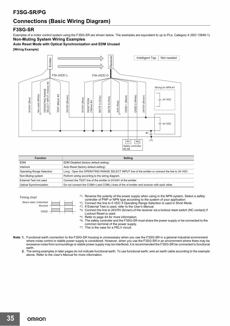
Connections (Basic Wiring Diagram)F3SG-SRExamples of a motor control system using the F3SG-SR are shown below. The examples are equivalent to up to PLe, Category 4 (ISO 13849-1).Non-Muting System Wiring ExamplesAuto Reset Mode with Optical Synchronization and EDM Unused [Wiring Example]
Note: 1. Functional earth connection to the F3SG-SR housing is unnecessary when you use the F3SG-SR in a general industrial environment where noise control or stable power supply is considered. However, when you use the F3SG-SR in an environment where there may be excessive noise from surroundings or stable power supply may be interfered, it is recommended the F3SG-SR be connected to functional earth.
2. The wiring examples in later pages do not indicate functional earth. To use functional earth, wire an earth cable according to the example above. Refer to the User's Manual for more information.
Beam state: UnblockedBlocked
OSSD
OS
SD
1 (
Bla
ck)
OS
SD
2 (
Whi
te)
24V
/0V
(B
row
n)
OP
ER
AT
ING
RA
NG
E
SE
LEC
T IN
PU
T (
Yel
low
) *
2
TE
ST
(B
lack
) *
3
Not
use
d (W
hite
)
24V
/0V
(B
row
n)
0V/2
4V (
Blu
e)
0V/2
4V (
Blu
e)
AU
X (
Red
)
MU
TE
B (
Pin
k)
MU
TE
A (
Gra
y)
F39-JG�C-L F39-JG�C-D
Timing chart
24 VDC
Wiring for NPN *1
*7
24 VDC
IN1
Safety controller*5 *6
IN2
RE
SE
T/E
DM
(Y
ello
w) *
4
Rec
eive
r
Em
itter Intelligent Tap Not needed
*1. Reverse the polarity of the power supply when using in the NPN system. Select a safety controller of PNP or NPN type according to the system of your application.
*2. Connect the line to 0 VDC if Operating Range Selection is used in Short Mode.*3. If External Test is used, refer to the User's Manual.*4. Connect the line to 24V/0V (brown) of the receiver via a lockout reset switch (NC contact) if
Lockout Reset is used.*5. Refer to page 44 for more information.*6. The safety controller and the F3SG-SR must share the power supply or be connected to the
common terminal of the power supply.*7. This is the case for a PELV circuit.
Function SettingEDM EDM Disabled (factory default setting)Interlock Auto Reset (factory default setting)Operating Range Selection Long : Open the OPERATING RANGE SELECT INPUT line of the emitter or connect the line to 24 VDC.Non-Muting system Perform wiring according to the wiring diagram.External Test not used Connect the TEST line of the emitter to 0V/24V of the emitter.Optical Synchronization Do not connect the COM(+) and COM(-) lines of the of emitter and receiver with each other.
F3SG-SR/PG
36
Conn
ectio
ns (B
asic
Wiri
ng D
iagr
am)
Auto Reset Mode with Wired Synchronization and EDM Unused[Wiring Example]
Note: For the functional earth connection, refer to page 35.
Beam state: UnblockedBlocked
OSSD
OS
SD
(B
lack
)
OS
SD
(W
hite
)
24V
/0V
(B
row
n)
CO
M(-
) (Y
ello
w)
TE
ST
(B
lack
) *
2
CO
M(+
) (W
hite
)
24V
/0V
(B
row
n)
0V/2
4V (
Blu
e)
0V/2
4V (
Blu
e)
AU
X (
Red
)
CO
M(-
) (P
ink)
CO
M(+
) (G
ray)
F39-JG�C-L F39-JG�C-D
Timing chart
24 VDC
Wiring for NPN *1
24 VDC
IN1 IN2
RE
SE
T/E
DM
(Y
ello
w) *
3
*6R
ecei
ver
Em
itter
Safety controller*4 *5
Not neededIntelligent Tap
Function SettingEDM EDM Disabled (factory default setting)Interlock Auto Reset (factory default setting)Operating Range Selection Long (factory default setting) *7Non-Muting system Perform wiring according to the wiring diagram.External Test not used Connect the TEST line of the emitter to 0V/24V of the emitter.Optical Synchronization Connect the COM(+) and COM(-) line of the emitter and receiver with each other.
*1. Reverse the polarity of the power supply when using in the NPN system. Select a safety controller of PNP or NPN type according to the system of your application.
*2. If External Test is used, refer to the User's Manual.*3. Connect the line to 24V/0V (brown) of the receiver via a lockout reset switch (NC contact) if
Lockout Reset is used.*4. Refer to page 44 for more information.*5. The safety controller and the F3SG-SR must share the power supply or be connected to the
common terminal of the power supply.*6. This is the case for a PELV circuit.*7. The Intelligent Tap is needed to set the Short mode. Set the function with the DIP Switches on
the Intelligent Tap or the SD Manager 3, restore the settings to the F3SG-SR, and perform wiring according to the wiring diagram.
F3SG-SR/PG
37
Manual Reset Mode with EDM[Wiring Example]
Note: For the functional earth connection, refer to page 35.
KM1
KM2
M
F39-JG�C-L F39-JG�C-D
Timing chart
24 VDC
Wiring for NPN *1
*3
24 VDC
KM1
KM2
S2
S1
KM1 KM2
S1: Test switchS2: Lockout/interlock reset switch KM1, KM2: Safety relay with forcibly guided contacts (G7SA) or magnetic contactorM: Motor
Beam state: UnblockedBlocked
Test switch (S1)
Reset switch (S2)
OSSD
Rec
eive
r
Em
itter
OS
SD
1 (
Bla
ck)
OS
SD
2 (
Whi
te)
24V
/0V
(B
row
n)
OP
ER
AT
ING
RA
NG
E
SE
LEC
T IN
PU
T (
Yel
low
) *
2
TE
ST
(B
lack
)
Not
use
d (W
hite
)
24V
/0V
(B
row
n)
0V/2
4V (
Blu
e)
0V/2
4V (
Blu
e)
AU
X (
Red
)
MU
TE
B (
Pin
k)
MU
TE
A (
Gra
y)
RE
SE
T/E
DM
(Y
ello
w)
NeededIntelligent Tap
*1. Reverse the polarity of the power supply when using in the NPN system.*2. Connect the line to 0 VDC if Operating Range Selection is used in Short
Mode.*3. This is the case for a PELV circuit.*4. Set the function with the DIP Switches on the Intelligent Tap or the SD
Manager 3, restore the settings to the F3SG-SR, and perform wiring according to the wiring diagram.
*5. This wiring example shows light emission stop when connected to 24 VDC with PNP setting, and light emission stop when connected to 0 VDC with NPN setting. If TEST switch is not needed, refer to the User's Manual.
Operating Range SelectionLong : Open the OPERATING RANGE SELECT INPUT line of the emitter or connect the line to 24 VDC.
Long *4 [Operating Range Selection] : Long mode *4
Non-Muting systemPerform wiring according to the wiring diagram.N/A [Muting] : Disable *4
External Test usedConnect the TEST line of the emitter to 24V/0V of the emitter via a test switch (NO contact).*5N/A [External test signal inversion] : Disable
Optical Synchronization Do not connect the COM(+) and COM(-) lines of the of emitter and receiver with each other.
4 ON
5 ON
8 ON
F3SG-SR/PG
38
Conn
ectio
ns (B
asic
Wiri
ng D
iagr
am)
Manual Reset Mode with EDM and Y-Joint Plug/Socket Connector[Wiring Example]
Note: 1. When using the Y-Joint Plug/Socket Connector (F39-GCNY2), the following functions are not available.• External Test• Operating Range Selection by wiring• Wired Synchronization
2. For the functional earth connection, refer to page 35.
F39-JGR3K-L and F39-JG□B-L
F39-GCNY2
F39-JG�A-D
24 VDC
Wiring for NPN *1
*3
24 VDC
Timing chart
F39-JGR3K-D and F39-JG□B-D
IN
PLC *2
KM1
KM2
M
KM1
KM2
S1
KM1 KM2
Beam state: UnblockedBlocked
Reset switch (S)
OSSD
S1: Lockout/interlock reset switch KM1, KM2: Safety relay with forcibly guided contacts (G7SA) or magnetic contactorM: MotorPLC: Programmable logic controller (Used for monitoring only. NOT related to
safety system.)
OS
SD
1 (
Bla
ck)
OS
SD
2 (
Whi
te)
24V
/0V
(B
row
n)
0V/2
4V (
Blu
e)
AU
X (
Red
)
MU
TE
B (
Pin
k)
MU
TE
A (
Gra
y)
RE
SE
T/E
DM
(Y
ello
w)
Rec
eive
r
Em
itter NeededIntelligent Tap
*1. Reverse the polarity of the power supply when using in the NPN system. Select a PLC of PNP or NPN type according to the system of your application.
*2. When connecting to the PLC, the output mode must be changed with the SD Manager 3 according to your application. For the setting this function, refer to the User's Manual.
*3. This is the case for a PELV circuit.*4. Set the function with the DIP Switches on the Intelligent Tap or the SD
Manager 3, restore the settings to the F3SG-SR, and perform wiring according to the wiring diagram.
*5. To set the Short mode, set the function with the DIP Switches on the Intelligent Tap or the SD Manager 3, restore the settings to the F3SG-SR, and perform wiring according to the wiring diagram.
Operating Range Selection *5Long (factory default setting)
Long [Operating Range Selection] : Long mode
Non-Muting systemPerform wiring according to the wiring diagram.N/A [Muting] : Disable *4
External Test not used N/AOptical Synchronization Connect the wires according to the diagram above.
4 ON5 ON
8 ON
F3SG-SR/PG
39
Manual Reset Mode with Intelligent Tap[Wiring Example]
Note: 1. When using the Intelligent Tap (F39-SGIT-IL3) with the emitter and receiver connected, the following functions are not available.• External Test• Operating Range Selection by wiring• Optical Synchronization
2. For the functional earth connection, refer to page 35.
*1. Reverse the polarity of the power supply when using in the NPN system. Select a PLC and a safety controller of PNP or NPN type according to the system of your application.
*2. When connecting to the PLC, the output mode must be changed with the SD Manager 3 according to your application. For the setting this function, refer to the User's Manual (Man.No.Z405).
*3. Refer to page 75 for more information.*4. The safety controller and the F3SG-SR must share the power supply
or be connected to the common terminal of the power supply.*5. For connecting with the IO-Link Master unit, refer to an instruction
manual of the IO-Link Master unit you use.*6. This is the case for a PELV circuit.
Operating Range Selection Long [Operating Range Selection] : Long mode
Non-Muting systemPerform wiring according to the wiring diagram.N/A [Muting] : Disable
Test Input N/AWired Synchronization Connect the emitter and receiver with the Intelligent Tap.
3 ON
4 ON5 ON
8 ON
F3SG-SR/PG
40
Conn
ectio
ns (B
asic
Wiri
ng D
iagr
am)
Manual Reset Mode with Reset Switch Connector[Wiring Example]
Note: 1. When using the Reset Switch Connector (F39-GCNY3), the following functions are not available.• External Device Monitoring (EDM)
2. For the functional earth connection, refer to page 35.
S2S1
24 VDC
24 VDC
F39-JG�C-L F39-GCNY3
F39-JGR3K-D
XS5F-D421�80-FF39-JG�A-D
IN1 IN2
L1
Wiring for NPN *1
OS
SD
1 (
Bla
ck)
OS
SD
2 (
Whi
te)
24V
/0V
(B
row
n)
TE
ST
(B
lack
)
Not
use
d (W
hite
)
24V
/0V
(B
row
n)
0V/2
4V (
Blu
e)
0V/2
4V (
Blu
e)
AU
X (
Red
)
MU
TE
B (
Pin
k)
MU
TE
A (
Gra
y)
RE
SE
T (
Yello
w)
0V/2
4V (
Blu
e)
RE
SE
T (
Whi
te)
24V
/0V
(B
row
n)
AU
X (
Bla
ck)
OP
ER
ATIN
G
RA
NG
E S
ELE
CT
IN
PU
T (
Yello
w) *
2E
mitt
er
Rec
eive
rSafety controller *3 *4
Timing chart
Beam state: UnblockedBlocked
Reset switch (S2)
Test switch (S1)
OSSD
S1: Test switchS2: Lockout/interlock reset switchL1: Lamp
*5
Innteligent Tap Needed
*1. Reverse the polarity of the power supply when using in the NPN system. Select a PLC and a safety controller of PNP or NPN type according to the system of your application.
*2. Connect the line to 0 VDC if Operating Range Selection is used in Short Mode.
*3. Refer to page 75 for more information.*4. The safety controller and the F3SG-SR must share the power
supply or be connected to the common terminal of the power supply.
*5. This is the case for a PELV circuit.*6. Set the function with the DIP Switches on the Intelligent Tap or the
SD Manager 3, restore the settings to the F3SG-SR, and perform wiring according to the wiring diagram.
*7. This wiring example shows light emission stop when connected to 24 VDC with PNP setting, and light emission stop when connected to 0 VDC with NPN setting. If TEST switch is not needed, refer to the User's Manual (Man. No. Z405).
Operating Range SelectionLong : Open the OPERATING RANGE SELECT INPUT line of the emitter or connect the line to 24 VDC.
Long *6 [Operating Range Selection] : Long mode *6
Non-Muting systemPerform wiring according to the wiring diagram.N/A [Muting] : Disable *6
External Test usedConnect the TEST line of the emitter to 24V/0V of the emitter via a test switch (NO contact). *7N/A [External test signal inversion] : Disable
Optical Synchronization Open the COM(+) and COM(-) lines of the emitter.
4 ON5 ON
8 ON
F3SG-SR/PG
41
Double Break with EDM[Wiring Example]
Note: For the functional earth connection, refer to page 35.
24V
/0V
(B
row
n)
0V/2
4V (
Blu
e)
Not
use
d (P
ink)
PS
DI (
Gra
y)
0V/2
4V (
Blu
e)
Not
use
d (W
hite
)
OPE
RATI
NG R
ANG
E SE
LECT
INPU
T (Y
ello
w)*
2
TE
ST
(B
lack
)
24V
/0V
(B
row
n)
RE
SE
T/E
DM
(Y
ello
w)
AU
X (
Red
)
OS
SD
1 (
Bla
ck)
OS
SD
2 (
Whi
te)
F39-JG�C-L F39-JG�C-D
24 VDC
Wiring for NPN *1
24 VDC
KM1
KM2
S2
S3
S1
0 VDC
KM1 KM2
*4IN
PLC *3
KM1
KM2
MCam
S3Rec
eive
r
Em
itter
S1: Test switchS2: Reset switchS3: Press position switchKM1, KM2: Safety relay with forcibly guided contacts (G7SA)
or magnetic contactorPLC: Programmable logic controller (Used for monitoring only.
NOT related to safety system.)M: Motor
Timing chart
Reset switch (S2)
Press position switch (S3)
OSSD
T1min.
T2min.
T4min.
T5min.
T5min.
T2min.
T3min.
T4min.
T3min.
Dummybreak
T1min.
T2min.
T3min.
T4min.
T6 Machine stops Machine restarts
Feedingparts
Feedingparts
Removingparts
Unintendedblock
Dummybreak *
Dummybreak *
UnblockedBlocked
T1: Minimum pressing time of reset switch. Configurable from 100 to 500 ms in 100-ms increments by SD Manager 3.T2: Minimum break time (300 ms)T3: Minimum unblocked time during the time from removing to feeding parts. T3 = T1T4: Minimum break time (300 ms)T5: Minimum pressing time of press position switch. T5 = T1T6: Wait time until double break is complete (30 s or less)
* When the machine is stopped by unintended block in the middle of pressing of parts, operation of the reset switch (S1) and then double dummy break are needed for reinitiation of the machine cycle.
Intelligent Tap Needed *5
: Indicates a switch position.
FunctionSetting
DIP switch SD Manager 3EDM - [External device monitoring] : Enable *5Operating Range Selection Short : Connect the OPERATING RANGE SELECT INPUT line of the emitter to 0 VDC.PSDI N/A [PSDI] : Double break *5
Non-Muting systemPerform wiring according to the wiring diagram.N/A [Muting] : Disable *5
External Test usedConnect the TEST line of the emitter to 24V/0V of the emitter via a test switch (NO contact). *6N/A [External test signal inversion] : Disable
Optical Synchronization Do not connect the COM(+) and COM(-) lines of the of emitter and receiver with each other.
*1. Reverse the polarity of the power supply when using in the NPN system. Select a PLC of PNP or NPN type according to the system of your application.
*2. Open or connect the line to 24 VDC if Operating Range Selection is used in Long Mode.
*3. When connecting to the PLC, the output mode must be changed with the SD Manager 3 according to your application. For the setting this function, refer to the User's Manual (Man.No.Z405).
*4. This is the case for a PELV circuit.*5. Set the function with the SD Manager 3, restore the settings to the
F3SG-SR, and perform wiring according to the wiring diagram.*6. This wiring example shows light emission stop when connected to
24 VDC with PNP setting, and light emission stop when connected to 0 VDC with NPN setting. If TEST switch is not needed, refer to the User's Manual (Man. No. Z405).
F3SG-SR/PG
42
Conn
ectio
ns (B
asic
Wiri
ng D
iagr
am)
Muting System Wiring ExamplesStandard Muting Mode/Exit-Only Muting mode[Wiring Example]
Note: For the functional earth connection, refer to page 35.
F39-JG�C-L F39-JG�C-D
24 VDC
Wiring for NPN *1
24 VDC
S3 S4*4
IN
PLC *5
*8
IN1
Safety controller *6 *7
IN2
S1
S2
Rec
eive
r
Em
itter
OS
SD
1 (
Bla
ck)
OS
SD
2 (
Whi
te)
24V
/0V
(B
row
n)
OPE
RATI
NG R
ANG
E SE
LECT
INPU
T (Y
ello
w) *
2
TE
ST
(B
lack
)
Not
use
d (W
hite
)
24V
/0V
(B
row
n)
0V/2
4V (
Blu
e)
0V/2
4V (
Blu
e)
AU
X (
Red
)
MU
TE
B (
Pin
k)
MU
TE
A (
Gra
y)
RE
SE
T/E
DM
(Y
ello
w) *
3
S1: Test switchS2: Lockout reset switch, override switch or override cancel switchS3, S4: Muting sensorPLC: Programmable logic controller (Used for monitoring only.
NOT related to safety system.)
MUTE A
MUTE B
Timing chart
Beam state: UnblockedBlocked
Test switch (S1)
OSSD
Intelligent Tap Needed *9
*1. Reverse the polarity of the power supply when using in the NPN system.
*2. Connect the line to 0 VDC if Operating Range Selection is used in Short Mode.
*3. Also used as OVERRIDE INPUT line.*4. Make sure to connect an override cancel switch to the RESET
line when using the override function. Otherwise the override state may not be released by the override cancel switch, resulting in serious injury.
*5. When connecting to the PLC, the output mode must be changed with the SD Manager 3 according to your application. For the setting this function, refer to the User's Manual (Man.No.Z405).
*6. Refer to page 75 for more information.*7. The safety controller and the F3SG-SR must share the power
supply or be connected to the common terminal of the power supply.
*8. This is the case for a PELV circuit.*9. Set the function with the SD Manager 3, restore the settings to
the F3SG-SR, and perform wiring according to the wiring diagram.
*10. This wiring example shows light emission stop when connected to 24 VDC with PNP setting, and light emission stop when connected to 0 VDC with NPN setting. If TEST switch is not needed, refer to the User's Manual (Man. No. Z405).
External Test usedConnect the TEST line of the emitter to 24V/0V of the emitter via a test switch (NO contact). *10N/A [External test signal inversion] : Disable
Optical Synchronization Open the COM(+) and COM(-) lines of the emitter.
F3SG-SR/PG
43
Standard Muting Mode/Exit-Only Muting mode with Intelligent Tap[Wiring Example]
Note: 1. When using the Intelligent Tap (F39-SGIT-IL3), the following functions are not available.• External Test• Operating Range Selection by wiring• Optical Synchronization
2. For the functional earth connection, refer to page 35.
S1 S2 S3*3
*8
F39-SGIT-IL3
24 VDC
Wiring for NPN *1
24 VDC
IO-LinkMaster *7
F39-JG�B-L/XS5F-D521-DJ0-IL
F39-JG�A-D
F39-JGR3K-L and F39-JG□B-L F39-JGR3K-D and F39-JG□B-D
IN
PLC *4
IN1
Safety controller *5 *6
IN2
Rec
eive
r
Em
itter
OS
SD
1 (
Bla
ck)
OS
SD
2 (
Whi
te)
24V
/0V
(B
row
n)
0V/2
4V (
Blu
e)
AU
X (
Red
)
MU
TE
B (
Pin
k)
MU
TE
A (
Gra
y)
RE
SE
T/E
DM
(Y
ello
w) *
2
MUTE A
MUTE B
OSSD
Timing chart
Beam state: UnblockedBlocked
S1: Lockout reset switch, override switch or override cancel switchS2, S3: Muting sensorPLC: Programmable logic controller (Used for monitoring only. NOT related to safety system.)
Test Input N/AWired Synchronization Connect the emitter and receiver with the Intelligent Tap.
3 ON
4 ON
5 ON
8 ON
*1. Reverse the polarity of the power supply when using in the NPN system. Select a PLC and a safety controller of PNP or NPN type according to the system of your application.
*2. Also used as OVERRIDE INPUT line.*3. Make sure to connect an override cancel switch to the
RESET line when using the override function. Otherwise the override state may not be released by the override cancel switch, resulting in serious injury.
*4. When connecting to the PLC, the output mode must be changed with the SD Manager 3 according to your application. For the setting this function, refer to the User's Manual (Man.No.Z405).
*5. Refer to page 75 for more information.*6. The safety controller and the F3SG-SR must share the
power supply or be connected to the common terminal of the power supply.
*7. For connecting with the IO-Link Master unit, refer to an instruction manual of the IO-Link Master unit you use.
*8. This is the case for a PELV circuit.
F3SG-SR/PG
44
Conn
ectio
ns (B
asic
Wiri
ng D
iagr
am)
Conn
ecta
ble
Safe
ty C
ontro
l Uni
ts
Connectable Safety Control UnitsThe F3SG-SR in the PNP system can be connected to the safety control units listed in the table below.
The F3SG-SR in the NPN system can be connected to the safety control unit listed in the table below.
For the connection to IO-Link with the Intelligent Tap, the F3SG-SR can be connected to the IO-Link Master unit listed in the table below.
* Connectable to units supporting IO-Link Version 1.1.
Connectable safety control units (PNP output)G9SA-301G9SA-321-TG9SA-501G9SB-200-BG9SB-200-DG9SB-301-BG9SB-301-DG9SE-201G9SE-401G9SE-221-TF3SP-T01
Connectable safety control units (NPN output)G9SA-301-P
Connectable IO-Link Master units *NX-ILM400GX-ILM08C
F3SG-SR/PG
45
Input/Output CircuitEntire Circuit DiagramThe entire circuit diagrams of the F3SG-SR are shown below.The numbers in the circles indicate the connector's pin numbers.
F3SG-SR
2
1
5
8
7
6
24V/0V1
2
4
Brown
Black TEST
White COM(+)
Blue
Brown
Yellow
White OSSD 2
Pink MUTE B/COM(-)
Gray MUTE A/PRE-RESET/PSDI/COM(+)
Black OSSD 1
Red AUX
Blue
3
4
3Muting input
circuit A
Reset input circuit
Muting input circuit B
RESET/EDM
0V/24V
5Yellow
Operating Range Select Input/COM(-)
Load
IndicatorABI
Emitter main circuit
Test input circuit
PNP/NPN select input circuit
PNP/NPN select input circuit
Operating range select input circuit
Receiver main circuit 2
ABI
Indi
cato
r
Load
Load
Receiver main circuit 1
Communication circuit
Communicationcircuit
F3SG-SR/PG
46
Inpu
t/Out
put C
ircui
t
Input Circuit Diagram by FunctionThe input circuit diagrams of by function are shown below.
Test Input
Operating Range Select Input
RESET/EDM, MUTE A/B
<Light emission stops when connected to 0 V>
0 VDC
<Light emission stops when connected to 24 VDC>
0 VDC
Short circuit current Approx. 5.0 mA
+24 VDC +24 VDC
Short circuit current Approx. 6.0 mA
Emitter main circuit
Emitter main circuit
<Short>
Emitter main circuit
+24 VDC
0 VDC
5 V
Short circuit current Approx. 4.2 mA
<Long>
+24 VDC
0 VDC
5 V
Emitter main circuit
Short circuit current Approx. 4.2 mA
Receivermain circuit
+24 VDC
0 VDC
Short circuit current *2
<NPN><PNP>
Receiver main circuit
+24 VDC
0 VDC
Short circuit current *1
*1. Short circuit current: approx. 9.5 mA (RESET/EDM), approx. 4.5 mA (MUTE A/B)
*2. Short circuit current: approx. 13.0 mA (RESET/EDM), approx. 7.0 mA (MUTE A/B)
F3SG-SR/PG
47
Dimensions (Unit: mm)
F3SG-SR SeriesMounted with Side-Mount Brackets (Intermediate Brackets) (F39-LSGF)Backside Mounting
250
max
. 2
50 m
ax.
F
10
P
D
250
max
. F
2
50 m
ax.
C
5.7
5
.7
<Screw: M5 or M6>
50
38
5.7
34.
4
6.3 dia.
C(P
rote
ctiv
e he
ight
)
32 46.7
Side-Mont Bracket(F39-LSGF)
Side-Mont Bracket(F39-LSGF)
2-M5 or M6
2-M5 or M6
* The number of brackets required to mount either one of emitter and receiver. The side-mount brackets (intermediate brackets) are included with the light curtain.
Dimension C 4-digit number of the type name (Protective height: )
0160 to 1440 2 1000 mm max.1520 to 2480 3 1000 mm max.
F3SG-SR/PG
48
Dim
ensi
ons
Side Mounting
Protective height (Dimension C)
Number of Side-Mount Bracket * Dimension F
0160 to 1440 2 1000 mm max.1520 to 2480 3 1000 mm max.
6.3 dia.
Side-MontBracket(F39-LSGF)
Side-MontBracket(F39-LSGF)
250
max
. 2
50 m
ax.
F
10
P
D
250
max
. F
2
50 m
ax.
C
8.2
8
.2
<Screw: M5 or M6>
38 50
8.2
19.4
46.7
C(P
rote
ctiv
e he
ight
)
32
2-M5 or M6
2-M5 or M6
* The number of brackets required to mount either one of emitter and receiver. The side-mount brackets (intermediate brackets) are included with the light curtain.
Dimension C 4-digit number of the type name (Protective height: )
Number of Adjustable Side-Mount Bracket * Dimension F
0160 to 0280 1 1000 mm max.0320 to 1440 2 1000 mm max.1520 to 2480 3 1000 mm max.
F3SG-SR/PG
51
Mounted with Adjustable Top/Bottom Brackets (F3SJ, F3SN Adapter) (F39-LSGTB-SJ) and Side-Mount Brackets (Intermediate Brackets) (F39-LSGF)Backside Mounting
34.
4
5.7
6.3 dia.
50
38 3.2
Adjustable Top/Bottom Bracket(F39-LSGTB-SJ)
12
Side-MontBracket(F39-LSGF)
Adjustable Top/Bottom Bracket(F39-LSGTB-SJ)
P
10
N2
D
C(P
rote
ctiv
e he
ight
)
G
H
I
F
9 dia. 19 32
46.7
5.8
1.7
N1
19
4-M5
C
F
G
5.7
2-M5 or M6
19
<Screw for AdjustableTop/Bottom Bracket: M5 *1>
C
F
H
5.7
2-M8
2-M5 or M6
<Screw for AdjustableTop/Bottom Bracket: M8 *1>
*1. Side-Mount Bracket: M5 or M6*2. For the model of protective height of 0160, the numbers corresponding to dimensions N1 and N2 are 20 to 30.*3. The number of brackets required to mount either one of emitter and receiver.*4. The side-mount brackets (intermediate brackets) are included with the light curtain.
Dimension C 4-digit number of the type name (Protective height: )
Dimension D
F3SG-SR-14C-20
F3SG-SR25F3SG-SR-45
C-40F3SG-SR-85
Dimension G C+27.2+N1+N2Dimension H C+38+N1+N2Dimension I C+58+N1+N2Dimension N1 0 to 30 *2Dimension N2 0 to 30 *2
0160 to 0840 2 0 ---0880 to1680 2 1 1000 mm max.1760 to 2480 2 2 1000 mm max.
F3SG-SR/PG
52
Dim
ensi
ons
Side Mounting
46.7
C
F
H
8.2
2-M8
2-M5 or M6
<Screw for AdjustableTop/Bottom Bracket: M8 *1>
19
4-M5
C
F
G
2-M5 or M6
8.2
19
<Screw for AdjustableTop/Bottom Bracket: M5 *1>
3.2
D
C(P
rote
ctiv
e he
ight
)
10
32
P
N2
F
N1
19
5.8
1.7
38
50
Adjustable Top/Bottom Bracket (F39-LSGTB-SJ)
Side-Mont Bracket(F39-LSGF)
I H
G
34.
4 8
.2
Adjustable Top/Bottom Bracket (F39-LSGTB-SJ)
9 dia.
6.3
dia.
*1. Side-Mount Bracket: M5 or M6*2. For the model of protective height of 0160, the numbers corresponding to dimensions N1 and N2 are 20 to 30.*3. The number of brackets required to mount either one of emitter and receiver.*4. The side-mount brackets (intermediate brackets) are included with the light curtain.
Dimension C 4-digit number of the type name (Protective height: )
Dimension D
F3SG-SR-14C-20
F3SG-SR25F3SG-SR-45
C-40F3SG-SR-85
Dimension G C+27.2+N1+N2Dimension H C+38+N1+N2Dimension I C+58+N1+N2Dimension N1 0 to 30 *2Dimension N2 0 to 30 *2
0160 to 0840 2 0 ---0880 to1680 2 1 1000 mm max.1760 to 2480 2 2 1000 mm max.
F3SG-SR/PG
53
Mounted with Adjustable Top/Bottom Brackets (F3SJ, F3SN Adapter) (F39-LSGTB-SJ) and Adjustable Side-Mount Brackets (Intermediate Brackets) (F39-LSGA)Backside Mounting
73
20
56.
5 6.3
4
50
<Screw for Adjustable Top/Bottom Bracket: M8 *1>
C 5
6.5
F
4
H
2-M8
2-M5 or M6
19
56.
5
19
2-M5 or M6
C
F
4
G
4-M5
<Screw for Adjustable Top/Bottom Bracket: M5 *1>
19
46.7 32
5.8
C(P
rote
ctiv
e he
ight
)
I
N2
N1
10
P
F
G
H
1.7
D
9 dia. 3.2
38 Adjustable Top/Bottom Bracket(F39-LSGTB-SJ)
12
Adjustable Top/Bottom Bracket(F39-LSGTB-SJ)
Adjustable Side-Mount Bracket (F39-LSGA)
*1. Adjustable Side-Mount Bracket: M5 or M6*2. For the model of protective height of 0160, the numbers corresponding to dimensions N1 and N2 are 20 to 30.*3. The number of brackets required to mount either one of emitter and receiver.
Dimension C 4-digit number of the type name (Protective height: )
Dimension D
F3SG-SR-14C-20
F3SG-SR25F3SG-SR-45
C-40F3SG-SR-85
Dimension G C+27.2+N1+N2Dimension H C+38+N1+N2Dimension I C+58+N1+N2Dimension N1 0 to 30 *2Dimension N2 0 to 30 *2
0160 to 0840 2 0 ---0880 to1680 2 1 1000 mm max.1760 to 2480 2 2 1000 mm max.
F3SG-SR/PG
54
Dim
ensi
ons
Side Mounting
46.7
2-M5 or M6
C
F
56.
5
4.2
H
2-M8
<Screw for AdjustableTop/Bottom Bracket: M8 *1>
19
19
56.
5
4.2
F
C
G
4-M5
2-M5 or M6
<Screw for AdjustableTop/Bottom Bracket: M5 *1>
3.2 32
F
C(P
rote
ctiv
e he
ight
)
N1
N2
10
P
D
5.8
6.3
1.7
9 dia.
4.2
56.
5
G
H
19 38
73
10
50
I 4.2
H
Adjustable Side-MountBracket (F39-LSGA)
Adjustable Top/Bottom Bracket (F39-LSGTB-SJ)
Adjustable Top/Bottom Bracket (F39-LSGTB-SJ)
*1. Adjustable Side-Mount Bracket: M5 or M6*2. For the model of protective height of 0160, the numbers corresponding to dimensions N1 and N2 are 20 to 30.*3. The number of brackets required to mount either one of emitter and receiver.
Dimension C 4-digit number of the type name (Protective height: )
Dimension D
F3SG-SR-14C-20
F3SG-SR25F3SG-SR-45
C-40F3SG-SR-85
Dimension G C+27.2+N1+N2Dimension H C+38+N1+N2Dimension I C+58+N1+N2Dimension N1 0 to 30 *2Dimension N2 0 to 30 *2
Cascading Cable for Extended (F39-JGR3W, sold separately) (two cables per set, one for emitter and one for receiver)Emitter Cascading Cable for Extended
Receiver Cascading Cable for Extended
Side-by-side Cascading Cable (F39-JGR12L, sold separately) (two cables per set, one for emitter and one for receiver)Side-by-side Cascading Cable for Emitter
Side-by-side Cascading Cable for Receiver
Conversion CableF3SJ-B/A Conversion Cable for Emitter (F39-JGR3K-SJ-L, sold separately)
Set model name Emitter cable (Gray) Receiver cable (Black) LengthF39-JGR3W F39-JGR3W-L F39-JGR3W-D 0.3 m
Set model name Emitter cable (Gray) Receiver cable (Black) LengthF39-JGR12L F39-JGR12L-L F39-JGR12L-D 12 cm
TroubleshootingF3SG-SRLOCKOUT StateIdentify an error according to the combination of the indicators when the error occurs. See the following troubleshooting tables to take measures.For detail, Refer to User’s Manual.
Illuminated Blink
Combination of indicators and error description<Indicator status at lockout: Receiver>
DIP Switch setting error
Operating range selection setting error
TOP Cap errorOther sensor error
Communication errorError other than those above
*1 *3
*2 *3BTM
Lor
LONG
Eor
ERR
Blinking once
ERR indicator
Blinking once
Eor
ERR
Blinking once
--- ---
---
Eor
ERR
[Error description]
Mor
MAINT
Mor
MAINT
Recoverable error
Red blinking : Replacement-recommended error
Orange blinking
Oor
OSSD
Por
PNP
For
CFG
TOP *1
BTM*2
Oor
OSSD
Error due to change of PNP/NPN polarity during operation
Safety output error due to power supply voltage or noise
Communication errorExternal device monitoring errorError other than those above
Intelligent Tap error
---
Safety Output error
Eor
ERR
Blinking twice
MAINT indicator
*1. For F3SG-SRA, the Area Beam Indicator closer to the "TOP" mark on the F3SG-SR blinks.*2. For F3SG-SRA, the Area Beam Indicator closer to the "BTM" mark on the F3SG-SR blinks.
Combination of indicators and error description<Indicator status at lockout: Emitter>
ERR indicator Other indicators Error description
*1. For F3SG-SRA, the Area Beam Indicator closer to the "TOP" mark on the F3SG-SR blinks.*2. For F3SG-SRA, the Area Beam Indicator closer to the "BTM" mark on the F3SG-SR blinks.*3. The indicator blinks only in the case the Wired Synchronization is enabled and is off in the case the Optical Synchronization is enabled.
Other indicators Error description
F3SG-SR/PG
65
Description
Checking byError code
(HEX)*1
Cause and measuresIndicator
SD Manager 3/SD Manager 3 Mobile APP
Safety output error X X
60, 6B, 6CThe OSSD lines may be short-circuited to each other or another signal line may be short-circuited to the OSSD line.Wire the OSSD lines properly.
56
The polarity does not match between the power supply and the OSSD lines.Check if a correct polarity is selected for the PNP/NPN setting according to your application. Also check:• if the power supply (0 VDC or 24 VDC) of the Intelligent
Tap and F3SG-SR is wired as intended.• if the OSSD lines are properly wired.
Recoverable error
X --- ---
The error may occur due to a temporary cause. Identify the cause by the status of the other LED indicator and take measures.
Replacement-recommended errorThe error may occur due to a product failure. If the measure according to the status of the other LED indicator does not work, it is recommended to replace the F3SG-SR.
Intelligent Tap error X --- ---
An error due to noise may have occurred in the internal circuit of the Intelligent Tap.Check the noise level in the environment.The internal circuit of the Intelligent Tap may be defective.Replace the Intelligent Tap.
Error due to change of PNP/NPN polarity during operation X X E7
An error due to noise may have occurred in the internal circuit.Check the noise level in the environment.The internal circuit may be defective.Replace the F3SG-SR.
Blanking monitoring error X X EC An error is detected by the Fixed Blanking Monitoringfunction or the Floating Blanking Monitoring function.
Configuration error X X
39, 3A, 3B
The cascading cable may be short-circuited, broken, or disconnected. Check that the cascading cable should be tightly connected. If the cascading cable is broken, replace it.The number of connected sensors or beams may have exceeded the maximum value due to cascading.Check the configuration.
3C, 3E, 3FA model name does not match between emitter and receiver. Check that the emitter and receiver are the same model.
34
An error may have occurred to the internal information of the model name of the F3SG-SR due to effect of noise.If other devices using the same power supply generate noise, do not share the same power supply with other devices, and use a separate power supply exclusively for the safety components.The inductive noise tends to be induced especially if the power supply line of the machine guarded and the power supply line of the Intelligent Tap are arranged in parallel.Arrange the exclusive power supply near the Intelligent Tap or lay the power supply line of the Intelligent Tap away from the power supply line of the machine guarded.If the power supply for the Intelligent Tap is located near the power supply of the machine guarded and it shares the same grounding wire, it is subject to the influence of common mode noise.Separate the grounding point or use it as the exclusive ground.An error may have occurred in the internal circuit.Replace the F3SG-SR.
Parameter error X XF1 The settings do not match between the Intelligent Tap and
F3SG-SR. Perform the Backup.
40 The settings of the F3SG-SR may be faulty. Check if the settings are correct.
*1. You can check the error codes by SD Manager 3 or SD Manager 3 Mobile APP.
F3SG-SR/PG
66
Trou
bles
hoot
ing
Cap error X X 4F A cap may be detached. Attach the cap properly.
Other sensor error X X 38 Other sensor being cascaded caused an error. Check the indicator of the sensor.
DIP Switch setting error X X E7, E8A DIP Switch on the Intelligent Tap setting may have been changed during operation.Check if a DIP Switch setting was changed or not.
Communication error --- X
30, 32The communication lines or other lines may be short-circuited or broken.Check if the cascading or extension cables. If the cascading cable or extension cables is broken, replace it.
31
An error may have occurred to the communication due to effect of noise.If other devices using the same power supply generate noise, do not share the same power supply with other devices, and use a separate power supply exclusively for the safety components.The inductive noise tends to be induced especially if the power supply line of the machine guarded and the power supply line of the Intelligent Tap are arranged in parallel.Arrange the exclusive power supply near the Intelligent Tap or lay the power supply line of the Intelligent Tap away from the power supply line of the machine guarded.If the power supply for the Intelligent Tap is located near the power supply of the machine guarded and it shares the same grounding wire, it is subject to the influence of common mode noise.Separate the grounding point or use it as the exclusive ground.An error may have occurred in the internal circuit.Replace the F3SG-SR.
Safety output error due to power supply voltage or noise X X
19
The power supply voltage may have dropped temporarily when the F3SG-SR is in operation. Check for temporary power supply voltage drop (by about 12 VDC) by the influence of the inductive load, etc.If the exclusive power supply is not used, check the power consumption of other connected devices for enough capacity.Power supply voltage may be outside the rated range.Connect the F3SG-SR to a 24 VDC±20% power supply voltage.Voltage fluctuation may have occurred due to insufficient power supply capacity.Replace the power supply with one that has a larger capacity.Instantaneous break or instantaneous stop may have occurred due to power sharing with other devices. Do not share the power supply with other devices. Connect the F3SG-SR to a power supply that is dedicated to electro-sensitive protective devices for electro-sensitive protective equipment such as the F3SG-SR, safety controller, etc.
1A
Effect of noise may be excessive.If other devices using the same power supply generate noise, do not share the same power supply with other devices, and use a separate power supply exclusively for the safety components.The inductive noise tends to be induced especially if the power supply line of the machine guarded and the power supply line of the F3SG-SR are arranged in parallel.Arrange the exclusive power supply near the F3SG-SR or lay the power supply line of the F3SG-SR away from the power supply line of the machine guarded.If the power supply for the F3SG-SR is located near the power supply of the machine guarded and it shares the same grounding wire, it is subject to the influence of common mode noise.Separate the grounding point or use it as the exclusive ground.
Description
Checking byError code
(HEX)*1
Cause and measuresIndicator
SD Manager 3/SD Manager 3 Mobile APP
*1. You can check the error codes by SD Manager 3 or SD Manager 3 Mobile APP.
F3SG-SR/PG
67
*1. You can check the error codes by SD Manager 3 or SD Manager 3 Mobile APP.*2. Other indicators than the ERR and MAINT indicators are not illuminated. For details of the error, refer to [Code] and [Error description] displayed
in [Error Log] in the SD Manager 3.
Operating range selection setting error X X EB
The setting of the operating range selection may be incorrect.• When the Intelligent Tap is connected, check if the
Operating Range Selection of the DIP Switch is properly set.
• When the Intelligent Tap is not connected, check if the Operating Range Select Input line is properly wired.
External device monitoring error ---*2 X 52
Relay may be welded. Replace the relay.The relay and the RESET line may not be properly wired. Check the wiring with the relay.The relay response time may be exceeding the allowable delay time. Change the allowable delay time or replace the relay with one that has an appropriate response time.
Error other than those above ---*2 X
Error code other than those above
An error may have occurred in the internal circuit.Replace the F3SG-SR.
Description
Checking byError code
(HEX)*1
Cause and measuresIndicator
SD Manager 3/SD Manager 3 Mobile APP
F3SG-SR/PG
68
Trou
bles
hoot
ing
WarningIdentify an error according to the combination of the indicators when the error occurs. See the following troubleshooting tables to take measures.For detail, Refer to User’s Manual.
*1. You can check the warning codes by SD Manager 3 or SD Manager 3 Mobile APP.*2. You can check by instantaneous block detection logs in [Instantaneous Block Detection Information].*3. The indicators are not illuminated. For details of the warning, refer to [Code] and [Warning description] displayed in [Warning Log] in the SD
Manager 3.
DescriptionChecking by Warning
code (HEX) *1
Cause and measuresIndicator SD Manager 3/
SD Manager 3 Mobile APPTeach-in error X X ED Teach-in failed. Perform the Teach-in again.
Muting sequence error X X 2C, 2D, 2FMuting input may have been applied in the incorrect order.Check the pattern of illumination of the LED indicator to identify the cause.
Interlock sequence error X --- ---When using the Pre-Reset function, the reset signals for interlock may be input in the wrong order. Check the pattern of illumination of the LED indicator to identify the cause.
PSDI sequence error X X 2A, 2BPSDI input may have been applied in the correct order. Check if the pattern of illumination of the LED indicator to identify the cause.
Malfunction due to ambient light or vibration X
X(SD Manager 3 Mobile APP is not applicable)
*2---
Malfunction may have occurred due to ambient light or instantaneous beam misalignment from vibration. Check the installation condition.
Low incident light level X X 12The incident light level may be low due to dirty front window or misaligned beams caused by vibration. Clean the front window and check the alignment of the beams.
Low communications quality
---*3 X F0
Retries of communications may have been generated due to noise. Check the noise level in the proximity of the communication lines.Retries of communications may have been generated due to short-circuit of the communication lines. Check the cables connected.
OFFBlinkingIlluminated
Combination of indicators and error description
<Indicator status at warning: Receiver *1>
ERR indicator Other indicatorsMAINT indicator Error description
Eor
ERR
Orange
*2
Sor
SEQ
Sor
SEQ
For
CFG
Mor
MAINT
Mor
MAINT
Area BeamIndicatorOrange
Area BeamIndicatorGreen
Low incident light level
Teach-in error
Muting sequence error, Interlock sequence error or PSDI sequence error
Malfunction due to ambient light or vibration
After 5 to 10 s
*1. In the warning state, no indicators on the emitter are illuminated or blink.*2. There are several illumination patterns to identify a faulty sequence.
F3SG-SR/PG
69
Muting Sequence Error IndicationThe following table is applied only when the muting function is being enabled.
* Factory default setting
Interlock Sequence Error IndicationThe following table is applied only when the pre-reset function is being enabled.
SEQ indicator Cause and measures
Blinking: Once
Power supply may have been turned ON with muting input A or B being ON.Check the condition of the muting sensors and the F3SG-SR.Muting input B may have been turned ON before muting input A was turned ON.Check the condition of the muting sensors.Muting input A and B may have been turned ON at the same time.• Check the arrangement of the muting sensors.• Check if the wiring of muting input A and B is short-circuited.
Either muting input A or B may have been turned ON with the F3SG-SR being blocked or INTERLOCK State.Check the condition of the F3SG-SR.
Blinking: Twice
Muting input B may have been turned ON within T1min (= 0.1 s *) after muting input A was turned ON.• Check that if the muting sensors are installed too close each other.• Check that if the speed of the workpiece is too fast.
It may have taken T1max (= 4 s *) or longer for muting input B to be turned ON after muting input A was turned ON.• Check that if the muting sensors are installed too far each other.• Check that if the speed of the workpiece is too slow.
The F3SG-SR may have been blocked after muting input A was turned ON but before muting input B was turned ON.Check the condition of the F3SG-SR.
Blinking: Four times
The F3SG-SR may have been blocked within 0.08 s after muting input A and B were normally turned ON.• Check that if the muting sensor and the F3SG-SR are installed too close each other.• Check that if the speed of the workpiece is too fast.
Muting may have been released after the F3SG-SR entered the MUTING state but before a workpiece blocked the F3SG-SR.• Check that the workpiece still remains.• Check that the speed of the workpiece is too slow.
Blinking: Five times
The F3SG-SR entered the MUTING state, but muting may have then been released while a workpiece passes through the F3SG-SR.• Check that the workpiece still remains.• Check that if the speed of the workpiece is too slow.• Check that the muting sensors have been installed upstream and downstream of the F3SG-SR with the size
of workpieces taken into account. (Using four muting sensors)
Blinking: Six timesMuting may have been released with muting input A and B remained ON after a workpiece passed through the F3SG-SR.• Check that the workpiece still remains.• Check that the speed of the workpiece is too slow.
Blinking: Seven timesThe next muting sequence may have started after muting was released but before the initial muting condition was established.• Check that if a next workpiece has not entered before the current workpiece passes through the F3SG-SR.• Check that if the interval between workpieces are too narrow.
SEQ indicator Cause and measures
Blinking: Once
The reset or pre-reset switch may have been pressed before the F3SG-SR receives light.Check the wiring of the reset and pre-reset signals.The F3SG-SR may have been blocked or the pre-reset switch may have been pressed before the pre-reset switch is pressed.Check the status of the F3SG-SR and the wiring of the pre-reset signal.
Blinking: TwiceAfter the pre-reset switch was pressed, the pre-reset or reset switch may have been pressed before the F3SG-SR is blocked.Check the installation environment of the F3SG-SR.
Blinking: Three times
After the pre-reset switch was pressed and the F3SG-SR was blocked, the pre-reset switch may have been pressed before the reset switch is pressed.Check the wiring of the pre-reset signal.After the pre-reset switch was pressed, a time period from the block of the F3SG-SR to the press of the reset switch may have exceeded the allowable time.Check the installation environment of the F3SG-SR as well as pre-reset and reset switches.The number of blocks of the F3SG-SR may have exceeded the allowable value after the pre-reset switch was pressed and before the reset switch is pressed.Check the installation environment of the F3SG-SR.
F3SG-SR/PG
70
Trou
bles
hoot
ing
PSDI Sequence Error IndicationThe following table is applied only when the PSDI function is being enabled.
Notations...Single Break...Double Break...Common
SEQ indicator Error condition Cause and measures
Blinking: Once
Power supply may have been turned ON with PSDI input being OFF.Check the condition of the light curtains and PSDI input wiring.Power supply may have been turned ON with the light curtain blocked.Check the condition of the light curtains and PSDI input wiring.Power supply may have been turned ON with RESET input being OFF.Check the condition of the light curtains and RESET input wiring.PSDI input may have been turned OFF before RESET input was turned OFF. Check the PSDI input wiring.The light curtain may have been blocked before RESET input was turned ON.Check the condition of the light curtains and RESET input wiring.The PSDI input may have turned OFF while the RESET input is OFF.Check the condition of the light curtains and PSDI input wiring. The light curtain may have been blocked before RESET input was turned ON. Check the condition of the light curtains and RESET input wiring.
Blinking: Twice
After RESET input , the light curtain may not be blocked longer than T2 and the PSDI input may have turned OFF.Check the condition of the light curtains and RESET input wiring.The PSDI input may have turned OFF with the light curtain blocked. Check the condition of the light curtains and PSDI input wiring.PSDI input may have turned OFF before the light curtain blocked twice.Check the condition of the light curtains and PSDI input wiring.
Blinking: Three times
The light curtain was blocked before the PSDI input turned OFF.Check the condition of the light curtains and PSDI input wiring.The light curtain was blocked while the PSDI input turned OFF.Check the condition of the light curtains and PSDI input wiring.
Blinking: Four times
PSDI input may have turned OFF during the period from when the PSDI state is canceled until the light curtain blocked. Check the condition of the light curtains and PSDI input wiring.The PSDI input may have turned OFF with the light curtain blocked. Check the condition of the light curtains and PSDI input wiring.It may have taken T4 (= 30 s) or longer for PSDI input to be turned OFF after the light curtain blocked.Check the condition of the light curtains and PSDI input wiring.It may have taken T6 (= 30 s) or longer for PSDI input to be turned OFF after the light curtain blocked.Check the condition of the light curtains and PSDI input wiring.The PSDI input may have turned OFF again before the light curtain blocked.Check the condition of the light curtains and PSDI input wiring.It may have taken T6 (= 30 s) or longer for PSDI input to be turned OFF after the light curtain blocked twice. Check the condition of the light curtains and PSDI input wiring.PSDI input may have turned OFF before the light curtain blocked again. Check the light curtain status and PSDI input wiring.
F3SG-SR/PG
71
Intelligent TapIf the Intelligent Tap detects any failure, it transitions to the LOCKOUT state. Under the LOCKOUT state, the ERR indicator is turned ON. Identify an error according to the combination of the indicators when the error occurs. See the following troubleshooting tables to take measures.For detail, Refer to User’s Manual.
Note: 1. The signals output to IO-Link or IN and OUT indicators show the statuses of the F3SG-SR or Intelligent Tap except their LOCKOUT state.2. The muting inputs A and B are kept in the OFF state when the LOCKOUT state occurs due to the power supply voltage error.
Description
Checking byError code
(HEX) *Cause and measures
IndicatorSD Manager 3/SD Manager 3 Mobile APP
Communication error X X 1D
The communication lines or other lines may be short-circuited or broken.Check the cables for cascading or extension cables.If the wiring is extended with cables other than specified, the cables used for extension may not have performance equivalent or greater than the specified cables. Use cables with the same performance or more than the specified cables.
Communication error in Backup X X 1E
The communication lines or other lines may be short-circuited or broken.Check the cables for cascading or extension cables.If the wiring is extended with cables other than specified, the cables used for extension may not have performance equivalent or greater than the specified cables. Use cables with the same performance or more than the specified cables.Effect of noise may be excessive.If other devices using the same power supply generate noise, do not share the same power supply with other devices, and use a separate power supply exclusively for the safety components.The inductive noise tends to be induced especially if the power supply line of the machine guarded and the power supply line of the Intelligent Tap are arranged in parallel.Arrange the exclusive power supply near the Intelligent Tap or lay the power supply line of the Intelligent Tap away from the power supply line of the machine guarded.If the power supply for the Intelligent Tap is located near the power supply of the machine guarded and it shares the same grounding wire, it is subject to the influence of common mode noise.Separate the grounding point or use it as the exclusive ground.The internal circuit of the Intelligent Tap may be defective.Replace the Intelligent Tap.
Communication error in Backup
Communication error in Restoration
Communication error between theF3SG-SR and the Intelligent Tap
Restoration failed
LOCKOUT state of the F3SG-SR
IO-Link circuit error
Power supply voltage error, orother errors
Green
Red
Green
Illuminated OFF Fast blinking Slow blinking
ERR(Red)
IN(Yellow)
OUT(Green/Red)
IO-Link(Green) Error description
Red
Combination of indicators and error description
Communication errorDIP Switch circuit error at startup
---
---
---
---
---------
--- ---
--- --- ---
---
F3SG-SR/PG
72
Trou
bles
hoot
ing
* You can check the error codes by SD Manager 3 or SD Manager 3 Mobile APP.
Communication error in Restoration
X X 1F
The communication lines or other lines may be short-circuited or broken.Check the cables for cascading or extension cables.If the wiring is extended with cables other than specified, the cables used for extension may not have performance equivalent or greater than the specified cables. Use cables with the same performance or more than the specified cables.Effect of noise may be excessive.If other devices using the same power supply generate noise, do not share the same power supply with other devices, and use a separate power supply exclusively for the safety components.The inductive noise tends to be induced especially if the power supply line of the machine guarded and the power supply line of the Intelligent Tap are arranged in parallel.Arrange the exclusive power supply near the Intelligent Tap or lay the power supply line of the Intelligent Tap away from the power supply line of the machine guarded.If the power supply for the Intelligent Tap is located near the power supply of the machine guarded and it shares the same grounding wire, it is subject to the influence of common mode noise.Separate the grounding point or use it as the exclusive ground.The internal circuit of the Intelligent Tap may be defective.Replace the Intelligent Tap.
Communication error between the F3SG-SR and the Intelligent Tap
X --- ---
The F3SG-SR may be disconnected from the Intelligent Tap, the communication line of the F3SG-SR may be broken, or the internal circuit of the Intelligent Tap may be defective. Check the connection and cable wiring between the Intelligent Tap and the F3SG-SR. In the case of defective internal circuit, replace the Intelligent Tap.
F3SG-SR LOCKOUT state X --- --- The F3SG-SR is in the LOCKOUT state. For details of the error of the F3SG-SR,
check the indicator status or error code of the F3SG-SR.
Restoration failed X --- ---
The sensor configuration (sensor model, connection configuration, etc.) that the Intelligent Tap stored by Backup does not match the sensor configuration of the connected the F3SG-SR. Connect the F3SG-SR with the same sensor configuration as the Backup sensor configuration. Error codes are not recorded.
Power supply voltage error, or other errors
X X A3
The muting inputs A and B are kept in the OFF state when the LOCKOUT state occurs due to the power supply voltage error.The power supply voltage may have dropped temporarily when the F3SG-SR is in operation. Check for temporary power supply voltage drop (by about 12 VDC) by the influence of the inductive load, etc.If the exclusive power supply is not used, check the power consumption of other connected devices for enough capacity.Power supply voltage may be outside the rated range.Connect the F3SG-SR to a 24 VDC±20% power supply voltage.Voltage fluctuation may have occurred due to insufficient power supply capacity.Replace the power supply with one that has a larger capacity.Instantaneous break or instantaneous stop may have occurred due to power sharing with other devices. Do not share the power supply with other devices. Connect the F3SG-SR to a power supply that is dedicated to electro-sensitive protective devices for electro-sensitive protective equipment such as the F3SG-SR, safety controller, etc.
DIP Switch circuit error at startup
X X BC The internal circuit may be defective.Replace the Intelligent Tap.
IO-Link circuit error X X BD The internal circuit may be defective.
Replace the Intelligent Tap.
Internal error X X Others The internal circuit may be defective.Replace the Intelligent Tap.
Description
Checking byError code
(HEX) *Cause and measures
IndicatorSD Manager 3/SD Manager 3 Mobile APP
F3SG-SR/PG
73
Bluetooth® Communication UnitSee the following troubleshooting table to take measures if any of the phenomena in the table occurs when in the connection with the BluetoothR Communication Unit.
* The procedure depends on the device you use for SD Manager 3. Refer to instruction manuals of the device.
Related Manuals
Status Measures
Communications cannot be established
Check if Bluetooth® Communication Unit is properly mounted.Check if Bluetooth® function is enabled on the device you use for SD Manager 3.Check if Bluetooth® Communication Unit is not being paired with another device.Check if Bluetooth® Communication Unit and the device you use for SD Manager 3 are properly paired (or the connection is verified). *Check if Bluetooth® function of the device you use for SD Manager 3 supports SPP (Serial Port Profile).Check if a COM port is properly configured.Check the noise level in the environment.Check if there is any device that uses 2.4 GHz band.Check if there is any obstruction between Bluetooth® Communication Unit and the device you use for SD Manager 3. The maximum permissible line-of-sight distance is approximately 10 m.The F3SG-SR is under the SETTING state. Turn OFF and ON the power of the F3SG-SR.
Files cannot be read from the outside while the sensor is connected
The sensor model in the saved file does not match the sensor model in the file that you are about to read in. Check the sensor model.If a file is saved by SD Manager 3 of a newer version than your SD Manager 3, the file is not usable on your SD Manager 3. Check the SD Manager 3 version.
F3SG-SR does not go back to normal state after terminating SD Manager 3
Restart F3SG-SR. If SD Manager 3 does not operate normally even after restarted, use the setup recovery function to restore to the factory default settings again.
Man.No. Model Manual NameZ405 F3SG-SR-- Safety Light Curtain F3SG-SR Series User's Manuals
• The Bluetooth® word mark and logo are registered trademarks and are owned by the Bluetooth SIG, Inc. and any use of such mark by OMRON Corporation is under license.
• USB Type-C™ is a trademark of USB Implementers Forum.• The product photographs and figures that are used in this catalog may vary somewhat from the actual products.• Other company names and product names in this document are the trademarks or registered trademarks of their respective companies.
OMRON CANADA, INC. • HEAD OFFICEToronto, ON, Canada • 416.286.6465 • 866.986.6766 • automation.omron.com
OMRON ELECTRONICS DE MEXICO • HEAD OFFICECiudad de México • 52.55.5901.4300 • 01.800.386.6766 • [email protected]
OMRON ELECTRONICS DE MEXICO • SALES OFFICESan Pedro Garza García, N.L. • 81.12.53.7392 • 01.800.386.6766 • [email protected]