Experience In Motion FLOWSERVE LIMITORQUE PROPRIETARY INFORMATION Flowserve’s proprietary rights are included in the information disclosed herein. Recipient, by accepting this document, agrees that neither this document nor the information disclosed herein nor any part thereof shall be reproduced or transferred to other documents or used or disclosed to others for manufacturing or for any other purpose except as specifically authorized in writing by Flowserve. Installation Operation Maintenance SAFETY MANUAL Limitorque MX Electronic Actuator FCD LMENIM2350-02 AQ – 05/16
Transcript
Experience In MotionFLOWSERVE LIMITORQUE PROPRIETARY INFORMATIONFlowserve’s proprietary rights are included in the information disclosed herein. Recipient, by accepting this document, agrees that neither this document nor the information disclosed herein nor any part thereof shall be reproduced or transferred to other documents or used or disclosed to others for manufacturing or for any other purpose except as specifically authorized in writing by Flowserve.
InstallationOperation
Maintenance
SAFETY MANUALLimitorque MX Electronic Actuator
FCD LMENIM2350-02 AQ – 05/16
Limitorque MX Electronic Actuator FCD LMENIM2350-02 AQ – 05/16
2
FLOWSERVE PROPRIETARY INFORMATIONUse or disclosure of this information is subject to the restrictions on the title page of this document
2.1.4 Dangerous, but Undetected (λDU) 7 2.2 Mission Time (Tmission) 7 2.3 Partial Stroke Test Period 7 2.4 Proof Test Period (Tpt) 8 2.5 FIT 8 2.6 Mean Time to Restoration (MTTR) 8 2.7 SFF 8 2.8 PFDavg 8 2.9 RRF 8 2.10 SIL vs. PFDavg vs. RFF 83 Safety Requirements 9 3.1 Monitor Relay Annunciation 9 3.2 Local Control Knobs Sensors 9 3.3 ESD Override for Knobs 9 3.4 The LCD Display May Also Indicate Warnings and Alarms 9 3.5 Partial Stroke Test Interval 9 3.6 Proof Test Interval 10 3.7 Basic Safety Configuration Requirements 10 3.8 Optional Emergency Overrides 10 3.9 Labeling 104 Design for Safety 11 4.1 LimiGard™ 12 4.2 Optional Safety Add-ons 12 4.2.1 Fire Protection 12 4.2.2 Safety Critical User Wiring 135 Limitorque MXa Safety Functions 14 5.1 Emergency Shutdown Open (ESD-Open) 14 5.2 Emergency Shutdown Close (ESD-Close) 14 5.3 Emergency Shutdown ‘Move To’ (ESD-Position) 14 5.4 Emergency Shutdown Stop (ESD-Stop) 14 5.5 Emergency Shutdown Ignore (ESD-Ignore) 14 5.6 Fail No-Action (Stay Put) Operation 15 5.7 Multiple ESD Functions for Basic PST 156 MXa Safety 16 6.1 PFDavg for MXa Actuator without PST 16 6.2 PFDavg for MXa Acutator with Monthly PST 177 Partial Stroke Testing [PST] 18 7.1 Basic PST Description 18 7.2 Enhanced PST Description 18 7.2.1 Monitor Relay Behavior When Configured as Enhanced PST 19
3
Limitorque MX Electronic Actuator FCD LMENIM2350-02 AQ – 05/16
flowserve.comFLOWSERVE PROPRIETARY INFORMATIONUse or disclosure of this information is subject to the restrictions on the title page of this document
7.3 Basic PST Configuration Options and Operation 19 7.3.1 Remote Input Option for Digital Input 1 (Terminal 34, or D2) 19 7.3.2 Monitor Relay Actions During PST 19 7.3.3 Digital Output (Relay Contact) Configuration Options for PST 20 7.3.4 PST Status Indicators 20 7.3.5 Recognition of Valid PST Signals 20 7.3.6 Rejection of PST signal 20 7.3.7 Actions on Recognition of Valid PST Signal 20 7.3.8 Actions upon Successful Completion of the PST Stroke 21 7.3.9 PST Timer 21 7.3.10 PST Timer Start 21 7.3.11 PST Failure Events and Actions 21 7.3.12 Actions During Power-Down Cycle During PST Event 228 Safety Instrumental System (SIS) Assessment 239 Commissioning 24 9.1 Internal Access Only via Terminal Compartment 24 9.2 Conduits and Unused Conduit Entries to be Sealed 24 9.3 Cable and Wire Routing 24 9.4 PST and PST/ESD Configuration 25 9.4.1 Basic Configuration 25 9.4.2 Enhanced Configuration 25 9.4.3 Access LCD Menu / Dialogue 25 9.4.4 Set Up Basic ESD and PST 27 9.4.5 Set Up Enhanced ESD and PST 2810 Emergency Shutdown (ESD) 29 10.1 Configurable ESD Actions 29 10.2 Configurable ESD Signal Logic 29 10.3 Configurable ESD Overrides 30 10.4 Remote External Interlocks/Inhibits 30 10.5 Custom Input Mode – Momentary ESD/PSESD (Optional) 3011 ESD (Emergency Shutdown) Overrides 31 11.1 ESD Override Setup Procedure 31 11.1.1 Inhibit Override 31 11.1.2 Local Command Override 32 11.1.3 Stop Override 32 11.1.4 Jammed Valve Override 32 11.1.5 Lost Phase Override 32 11.1.6 Over-Torque Override 32 11.1.7 Motor Thermostat Override 3212 Failure Analysis 3413 Instructions, Operation and Maintenance [IOM] 35 13.1 Normal Operation 35 13.2 Safety Operation and Maintenance 35 13.3 Estimated Repair Times 3514 Revision History 3615 Regulatory Information 37
Limitorque MX Electronic Actuator FCD LMENIM2350-02 AQ – 05/16
4
FLOWSERVE PROPRIETARY INFORMATIONUse or disclosure of this information is subject to the restrictions on the title page of this document
TablesTable 1.1 – Available Functional Options 5Table 2.1 – SIL vs PFDavg 8Table 6.1 – PFDavg for MXa Actuator without PST 16Table 6.2 – PFDavg for MXa Actuator with Monthly PST 16Table 7.1 – PST Status Indicators 20Table 12.1 – Expected Operation for Various Input Signal Combinations 34
Limitorque MX Electronic Actuator FCD LMENIM2350-02 AQ – 05/16
flowserve.comFLOWSERVE PROPRIETARY INFORMATIONUse or disclosure of this information is subject to the restrictions on the title page of this document
1 ScopeThis document is a Safety Manual for the Basic Limitorque™ MXa electronic actuator system with Standard Controls Package as developed for the Limitorque branded actuators that are manufactured by Flowserve Corporation.
Optional printed circuit boards may be included with the basic actuator as shown in the following table. However, while the inclusion of those options will not result in a change to the Safety Integrity Level [SIL], their use will result in a slight reduction in values for some of the safety metrics as shown in sections 6 and 8.
Table 1.1 – Available Functional Options
Function Part #
Digital Output (relays) 64-825-0043
Analog Output 64-825-0155
Network, Modbus (DDC) 64-825-0047
Network, Fieldbus H1Profibus PA 64-825-0173
Network, Profibus DP 64-825-0046
Network, DeviceNet 64-825-0097
UPS (24Vdc remote supply interface) 64-825-0132
QuikPower (backup Power) 64-825-0067
Arctic temperature components to (-60°C) 64-825-0157, 64-825-0101-4
Network, HART Part# 64-825-0176-02
Network Profibus PA Part# 64-825-0173-02
Network, HART Part# 64-825-0176-02
This document is intended to provide the necessary information to properly configure and use the Safety Instrumented Function [SIF] of the device within a Safety Instrument System [SIS] as defined by Standard IEC 61508. It contains detailed information on installation, commissioning, proof testing and diagnostics.
Approval Certificate without option boards: Exida #FLO 081012 C001, revision 1.1, dated January 13, 2012.
a CAUTION: Failure to apply the procedures that are described in this document may invalidate the safety function certification.
a CAUTION: This document must be used in conjunction with the latest version of the Limitorque Actuator Instruction and Operating Manual [IOM] Limitorque MXa - Instruction Manual - LMENIM2306.
The latest version can be found on the Flowserve website at www.flowserve.com.
NOTE: Documents may be obtained on the Internet at www.flowserve.com.
Limitorque MX Electronic Actuator FCD LMENIM2350-02 AQ – 05/16
6
FLOWSERVE PROPRIETARY INFORMATIONUse or disclosure of this information is subject to the restrictions on the title page of this document
1.1 System Overview
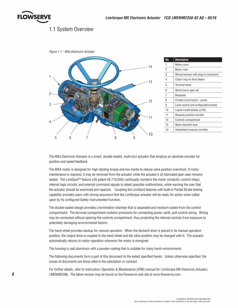
The MXa Electronic Actuator is a smart, double-sealed, multi-turn actuator that employs an absolute encoder for position and speed feedback.
The MXA motor is designed for high starting torque and low inertia to reduce valve position overshoot. If motor maintenance is required, it may be removed from the actuator while the actuator’s oil lubricated gear case remains sealed. The LimiGard™ feature (US patent #5,719,559) continually monitors the motor contactor, control relays, internal logic circuits, and external command signals to detect possible malfunctions, while warning the user that the actuator should be examined and repaired. Coupling the LimiGard features with built-in Partial Stroke testing capability provides users with strong assurance that the Limitorque actuator will be ready for action when called upon by its configured Safety Instrumented Function.
The double-sealed design provides a termination chamber that is separated and moisture sealed from the control compartment. The terminal compartment contains provisions for connecting power, earth, and control wiring. Wiring may be connected without opening the controls compartment, thus protecting the internal controls from exposure to potentially damaging environmental factors.
The hand wheel provides backup for manual operation. When the declutch lever is placed in its manual operation position, the output drive is coupled to the hand wheel and the valve position may be changed with it. The actuator automatically returns to motor operation whenever the motor is energized.
The housing is cast aluminum with a powder-coating that is suitable for many harsh environments.
The following documents form a part of this document to the extent specified herein. Unless otherwise specified, the issues of documents are those cited in the solicitation or contract.
For further details, refer to Instruction, Operation & Maintenance [IOM] manual for Limitorque MX Electronic Actuator, LMENIM2306. The latest version may be found on the Flowserve web site at www.flowserve.com.
No. Description
1 Motor cover
2 Motor rotor
3 Wiring harness with plug-in connectors
4 Clutch ring on drive sleeve
5 Terminal block
6 Worm/worm gear set
7 Baseplate
8 Printed circuit board – power
9 Local control and configuration knobs
10 Liquid crystal display [LCD]
11 Absolute position encoder
12 Controls compartment
13 Motor declutch lever
14 Handwheel (manual override)
1
2
3
4
5 6 7 8 910
11
12
13
14
Figure 1.1 – MXa Electronic Actuator
7
Limitorque MX Electronic Actuator FCD LMENIM2350-02 AQ – 05/16
flowserve.comFLOWSERVE PROPRIETARY INFORMATIONUse or disclosure of this information is subject to the restrictions on the title page of this document
2 Safety Integrity Level (SIL)
The international standard IEC 61508 defines four Safety Integrity Levels (SIL) from SIL 1 to SIL 4. Each level provides an expectation for the probability of a failure on demand for a given safety function. Higher SIL values indicate higher integrity against random failure probability that a safety function will perform when required (see Table 1 for relative comparisons) and higher integrity against systemic failures. The achievable SIL based upon random failure protection has been determined by using the following safety parameters:
2.1 Failure Rates/Failure Modes
2.1.1 Safe, but Detected (λSD)Rate per hour of failures that will result in a transition to the fail-safe state, but that will be detected and annunciated.
2.1.2 Safe, but Undetected (λSU)Rate per hour of failures that will result in a transition to the fail-safe state, but that cannot be detected.
2.1.3 Dangerous, but Detected (λDD)Rate per hour of failures that will prevent a transition to the fail-safe state when a demand occurs, but that will be detected and annunciated.
2.1.4 Dangerous, but Undetected (λDU)Rate per hour of failures that will prevent a transition to the fail-safe state when a demand occurs and that is not detected during normal operation. These failures may be detected by PST.
2.2 Mission Time (Tmission)Expected operating lifetime expressed in hours for device to provide safety function (10, 15 or 20 years).
2.3 Partial Stroke Test (PST) Period Minimum one PST per month ==> 730 hr
Failures can be uncovered during PST.
Limitorque MX Electronic Actuator FCD LMENIM2350-02 AQ – 05/16
8
FLOWSERVE PROPRIETARY INFORMATIONUse or disclosure of this information is subject to the restrictions on the title page of this document
2.4 Proof Test Period (Tpt)Full stroke test at least once per year ==> 8760 hr
Based upon the extent of the proof test, failures undetected during normal operation or during PST may be uncovered during full proof test.
2.5 Failures in Time (FIT)Number of failures in time.
2.6 Mean Time to Restoration (MTTR)Average failure detection time plus average repair time.
2.7 SFFSafe failure fraction.
2.8 PFDavg
The average probability of failure on demand for a safety function (approximate).
2.9 RRF Risk reduction factor.
2.10 SIL vs PFDavg vs RFFTable 1 is based upon “low-demand Mode,” i.e., the safety function is required to be operated no more frequently than twice the proof test period (see 2.4 ).
Table 2.1 - SIL vs PFDavg
SIL PFDavg RFF
4 10-5 … < 10-4 10,000 to 100,000
3 10-4 … < 10-3 1,000 to 10,000
2 10-3 … < 10-2 100 to 1000
1 10-2 … < 10-1 10 to 100
9
Limitorque MX Electronic Actuator FCD LMENIM2350-02 AQ – 05/16
flowserve.comFLOWSERVE PROPRIETARY INFORMATIONUse or disclosure of this information is subject to the restrictions on the title page of this document
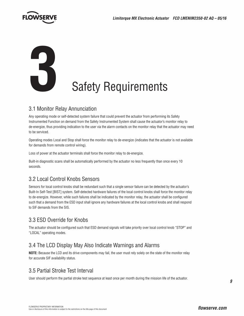
3 Safety Requirements
3.1 Monitor Relay AnnunciationAny operating mode or self-detected system failure that could prevent the actuator from performing its Safety Instrumented Function on demand from the Safety Instrumented System shall cause the actuator’s monitor relay to de-energize, thus providing indication to the user via the alarm contacts on the monitor relay that the actuator may need to be serviced.
Operating modes Local and Stop shall force the monitor relay to de-energize (indicates that the actuator is not available for demands from remote control wiring).
Loss of power at the actuator terminals shall force the monitor relay to de-energize.
Built-in diagnostic scans shall be automatically performed by the actuator no less frequently than once every 10 seconds.
3.2 Local Control Knobs SensorsSensors for local control knobs shall be redundant such that a single sensor failure can be detected by the actuator’s Built-In Self-Test [BIST] system. Self-detected hardware failures of the local control knobs shall force the monitor relay to de-energize. However, while such failures shall be indicated by the monitor relay, the actuator shall be configured such that a demand from the ESD input shall ignore any hardware failures at the local control knobs and shall respond to SIF demands from the SIS.
3.3 ESD Override for KnobsThe actuator should be configured such that ESD demand signals will take priority over local control knob “STOP” and “LOCAL” operating modes.
3.4 The LCD Display May Also Indicate Warnings and AlarmsNOTE: Because the LCD and its drive components may fail, the user must rely solely on the state of the monitor relay for accurate SIF availability status.
3.5 Partial Stroke Test IntervalUser should perform the partial stroke test sequence at least once per month during the mission life of the actuator.
Limitorque MX Electronic Actuator FCD LMENIM2350-02 AQ – 05/16
10
FLOWSERVE PROPRIETARY INFORMATIONUse or disclosure of this information is subject to the restrictions on the title page of this document
3.6 Proof Test IntervalUser should perform a full stroke proof test sequence at least once per year during the mission life of the actuator.
3.7 Basic Safety Configuration RequirementsActuator should be configured and wired for emergency operation and partial stroke testing as shown in section 9.4 of this document.
3.8 Optional Emergency OverridesThe user may choose to disable certain actuator protection features such that the actuator may sacrifice itself in order to attempt to achieve the demanded safe state during an emergency.
See “ESD (Emergency Shutdown) Overrides” in the IOM.
NOTE: The actuator warranty shall be voided if any of these protection features are disabled.
3.9 LabelingActuators that have been approved for operation in Safety Instrumented Systems shall have a label affixed that indicates its SIL rating.
11
Limitorque MX Electronic Actuator FCD LMENIM2350-02 AQ – 05/16
flowserve.comFLOWSERVE PROPRIETARY INFORMATIONUse or disclosure of this information is subject to the restrictions on the title page of this document
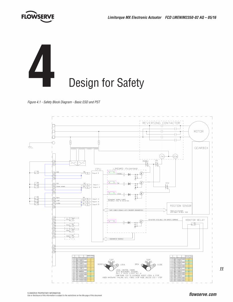
4 Design for SafetyFigure 4.1 - Safety Block Diagram - Basic ESD and PST
Case A‐B‐C‐D Meaning ActionMonitor RelayDe‐energises?
Limitorque MX Electronic Actuator FCD LMENIM2350-02 AQ – 05/16
12
FLOWSERVE PROPRIETARY INFORMATIONUse or disclosure of this information is subject to the restrictions on the title page of this document
4.1 LimiGard™LimiGard™ is at the heart of the design for safety that is integral to every Limitorque MXa and QX commercial and/or SIL-rated electric actuator.
LimiGard is a patented digital command and monitoring system that employs coded signals throughout and automati-cally monitors the health of each signal to ensure that no component failure in the signal path can cause the actuator to move unexpectedly.
Motor control signals are redundant in that two healthy signals must be present before the motor will be able to move. Both the enable signal and the direction signals (CW or CCW) must be present and healthy so that the motor will respond to the command. All command signals must also meet the waveform shape specifications to be considered healthy. If the command signal waveform does not meet the frequency and duty cycle specification, or fails to high or low DC voltage values, then no charge can be pumped through the charge pump and the command signal will not be passed to its target contactor coil.
The LimiGard feature also employs a function that can detect when a single output switch is “on.” Normally, zero switches are on when the motor is idle, and two switches are on when the motor is active. Whenever a single switch is on, the LimiGard feature detects that as a fault and alerts the user.
Operating mode signals from the knobs on the local control compartment are also redundant in the sense that there are four sensors to detect three valid knob positions. Each valid knob position requires signals from two of the four sensors. There are only five valid combinations out of the 16 possible sensor signal combinations that will be accepted as valid signals. All other combinations will be detected and reported as “Hardware Fault / Knobs.”
The absolute encoder position sensor also rests within the scope of LimiGard protection. The encoder includes several BIST features for which patents are pending. In particular, each data bit that comprises the resulting position value has been validated by the encoder to ensure that each bit signal transmitter and receiver is healthy. Whenever any data bit is determined to be unreliable or failed, the LimiGard feature alerts the user.
While most LimiGard alerts will be displayed on the digital screen in the window on the control compartment, some failures, such as power loss, CPU failure or LCD failure will make it impossible to show details of the failure on the digital display screen. The user should always rely on the state of the monitor relay, which will always de-energize whenever the actuator is not available to respond to remote demand signals.
Note: Although “Local” and “Stop” operating modes are not failures, the actuator will not normally respond to remote demand signals when it is in one of those modes. Therefore, the monitor relay will de-energize when the actuator is in one of those modes.
Note: For emergency operation, many users will want the actuator to respond to emergency shutdown demand signals, even if the operating mode is Local or Stop, or if some protective feature has been asserted by the actuator (e.g., motor over temperature, hardware fault/knob, hardware fault/encoder). Many such protection features can be overridden by the ESD function. However, by choosing to override the protection features to achieve a safety function at the expense of sacrificing the actuator will void factory warranty.
4.2 Optional Safety Add-ons
4.2.1 Fire ProtectionA self-sacrificing, fire-resistant coating may be applied to the actuator that will allow the actuator to continue func-tioning for 30 minutes while immersed in flame.
Fire protection has not been included in the calculations for SIL rating of the basic actuator.
13
Limitorque MX Electronic Actuator FCD LMENIM2350-02 AQ – 05/16
flowserve.comFLOWSERVE PROPRIETARY INFORMATIONUse or disclosure of this information is subject to the restrictions on the title page of this document
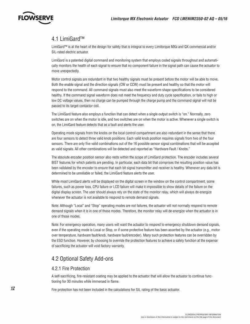
4.2.2 Safety Critical User WiringThe LimiGard concept can be extended to user wiring as shown in Safety Block Diagram - Enhanced User Wiring (Figure 4.2 below) and configuring the actuator in accordance with subsection 10.5, Custom Input Mode - Momentary ESD/PSESD (Optional).
NOTE: With enhanced PST/ESD configuration, a momentary ESD demand signal will be honored by the actuator, even if user wiring is subsequently destroyed during the emergency event.
Figure 4.2 - Safety Block Diagram - Enhanced User Wiring
Case A‐B‐C‐D Meaning ActionMonitor RelayDe‐energises?
Limitorque MX Electronic Actuator FCD LMENIM2350-02 AQ – 05/16
14
FLOWSERVE PROPRIETARY INFORMATIONUse or disclosure of this information is subject to the restrictions on the title page of this document
5 Limitorque MXa Safety Functions
5.1 Emergency Shutdown Open (ESD-Open)A remote, external ESD signal may be applied to the actuator to move the valve to the OPEN position through predeter-mined, user-configured shutdown position, overriding existing control signals.
5.2 Emergency Shutdown Close (ESD-Close)A remote, external ESD signal may be applied to the actuator to move the valve to the CLOSE position through predeter-mined, user-configured shutdown position, overriding existing control signals.
5.3 Emergency Shutdown ‘Move To’ (ESD-Position)A remote, external ESD signal may be applied to the actuator to move the valve to a target position through predeter-mined, user-configured target position, overriding existing control signals.
5.4 Emergency Shutdown Stop (ESD-Stop)A remote, external ESD signal may be applied to the actuator to stop in place, overriding existing control signals.
5.5 Emergency Shutdown Ignore (ESD-Ignore)A remote, external ESD signal may be applied to the actuator to ignore, thus remaining responsive to any other existing control signals.
15
Limitorque MX Electronic Actuator FCD LMENIM2350-02 AQ – 05/16
flowserve.comFLOWSERVE PROPRIETARY INFORMATIONUse or disclosure of this information is subject to the restrictions on the title page of this document
5.6 Fail No-Action (Stay Put) OperationThe system is designed so that any single-point failure in the microprocessor-controlled signal lines will automatically halt or prevent motor motion. We refer to this philosophy as “Fail No-Action.”
While not explicitly considered SIF, this implicit feature would reduce the risk in any SIS that would require the actuator to stay in place during an emergency.
5.7 Multiple ESD Functions for Basic PSTUp to two independent ESD signals may be applied, prioritized and configured for different actions for the ESD event associated with each.
ESD Priority 1: Digital Input 0 (Terminal 30)
ESD Priority 2: Digital Input 2 (Terminal 35) Signal is ignored if ESD Priority 1 is asserted.
Limitorque MX Electronic Actuator FCD LMENIM2350-02 AQ – 05/16
16
FLOWSERVE PROPRIETARY INFORMATIONUse or disclosure of this information is subject to the restrictions on the title page of this document
6 MXa Safety
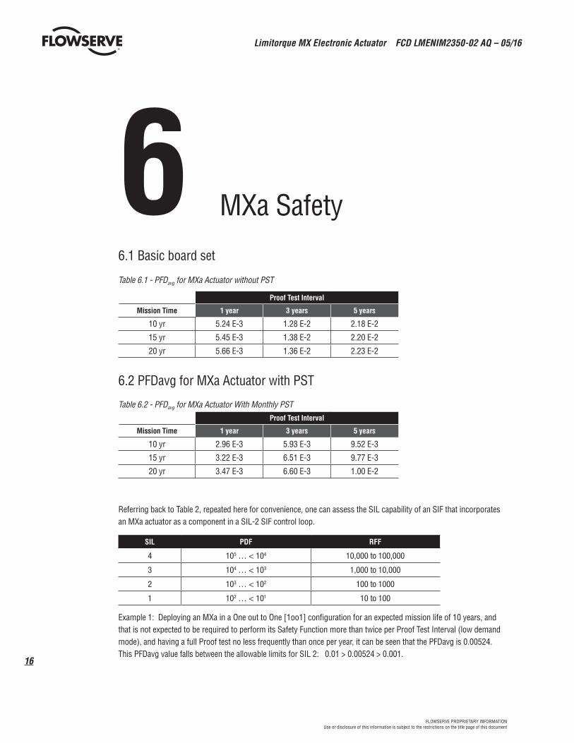
6.1 Basic board set
Table 6.1 - PFDavg for MXa Actuator without PST
Proof Test Interval
Mission Time 1 year 3 years 5 years
10 yr 5.24 E-3 1.28 E-2 2.18 E-2
15 yr 5.45 E-3 1.38 E-2 2.20 E-2
20 yr 5.66 E-3 1.36 E-2 2.23 E-2
6.2 PFDavg for MXa Actuator with PST
Table 6.2 - PFDavg for MXa Actuator With Monthly PSTProof Test Interval
Mission Time 1 year 3 years 5 years
10 yr 2.96 E-3 5.93 E-3 9.52 E-3
15 yr 3.22 E-3 6.51 E-3 9.77 E-3
20 yr 3.47 E-3 6.60 E-3 1.00 E-2
Referring back to Table 2, repeated here for convenience, one can assess the SIL capability of an SIF that incorporates an MXa actuator as a component in a SIL-2 SIF control loop.
SIL PDF RFF
4 105 … < 104 10,000 to 100,000
3 104 … < 103 1,000 to 10,000
2 103 … < 102 100 to 1000
1 102 … < 101 10 to 100
Example 1: Deploying an MXa in a One out to One [1oo1] configuration for an expected mission life of 10 years, and that is not expected to be required to perform its Safety Function more than twice per Proof Test Interval (low demand mode), and having a full Proof test no less frequently than once per year, it can be seen that the PFDavg is 0.00524. This PFDavg value falls between the allowable limits for SIL 2: 0.01 > 0.00524 > 0.001.
17
Limitorque MX Electronic Actuator FCD LMENIM2350-02 AQ – 05/16
flowserve.comFLOWSERVE PROPRIETARY INFORMATIONUse or disclosure of this information is subject to the restrictions on the title page of this document
In other words, using an MXa in an SIL-2 SIF will absorb 52.4% of the available bandwidth for SIL-2. In order to maintain a SIL-2 capability for the entire SIF, the total of the PFDavg values for all of the components that comprise the SIF must sum to no more than 0.01. Therefore the total of the PFDavg values for all of the other components that comprise the SIF control loop must be less than 0.01-0.00524 = 0.00476, or 47.6% of the SIL-2 bandwidth.
Note that available bandwidth for other components can be easily increased for the identical actuator simply by performing a monthly Partial Stroke Test [PST].
Continuing with the previous example, by performing a monthly Partial Stroke Test [PST] in addition to a yearly Full Proof Test, the PFDavg for the MXa is reduced to only 0.00347, which is only 34.7% of the SIL-2 bandwidth, The available bandwidth for all of the other components is now 0.01 - 0.00347 = 0.00704. That is, 70.4% of the SIL-2 bandwidth is available for all of the other components that comprise the SIL control loop.
The MXa is able to perform PST because SIF and PST functions do not bypass the normal controls and position feedback mechanisms.
6.2 Basic plus any optional board add-on
Optional functions may be added to the basic functionality of the basic actuator by the addition of various printed circuit boards. (See Table 1 – Available Functional Add-ons on page 5)
None of these add-ons will contribute to operation of the Safety Function [SIF], but may be used for additional control and/or monitoring of the actuator for non SIF operation.
Inclusion of these add-ons will minimally affect the Probability of Failures on Demand [PFDavg) values shown in Table 3 and Table 4, above. To determine the actual PFDavg for the optional add-ons to be deployed, the user should refer to the failure rate data as shown in FMEDA assessment reports and noted in section 8 Safety Instrumented System [SIS] Assessment on page 23.
Limitorque MX Electronic Actuator FCD LMENIM2350-02 AQ – 05/16
18
FLOWSERVE PROPRIETARY INFORMATIONUse or disclosure of this information is subject to the restrictions on the title page of this document
7 Partial Stroke Testing (PST)
To ensure that the actuator remains ready to perform its safety function and to detect those faults that the actuator cannot discover by its automated Built-In Self-Test [BIST], it is strongly recommend that the user should perform periodic Partial Stroke Testing [PST]. By moving the actuator through a small portion of its stroke, the user can gain assurance that the unit remains healthy enough to perform its safety function.
The Limitorque MXa actuator supports two operating configurations for PST:
7.1 Basic PST DescriptionAvailable as a configuration option in all MXa actuators, basic PST tests and exercises all of the control circuitry needed to move the actuator and its driven equipment.
Reference Figure 4.1 Safety Block Diagram - Basic ESD and PST on page 11.
7.2 Enhanced PST DescriptionAvailable as a purchased add-on, enhanced PST performs all of the tests that are performed by basic PST, but also extends coverage to the user’s wiring and Safety Instrument System control equipment. Note especially that in this configuration, the PST signal uses the same user control and actuator inputs as the ESD signals. Therefore, by performing a PST in this configuration, the user is also explicitly testing his own ESD signaling for this actuator.
Reference Figure 4.2 Safety Block Diagram - Enhanced User Wiring on page 13.
The ESD release signals are set up as redundant signals for safety. There are two signal inputs, and BOTH must be in the active state. If there is an active ESD and both ESD release inputs are in the active state, the ESD will be unlatched and the unit will return to normal operation. If the ESD release inputs are in a fault state, an active ESD will NOT be released. The ESD release inputs will have no effect on a partial stroke ESD test.
The momentary ESD/PSESD input will be ignored if the signal is present for less than 100msec, and is guaranteed to latch the ESD/PSESD if the signal is present for greater than 800msec. Once the ESD is latched, the unit will perform the ESD action.
The partial stroke enable signals are set up as redundant signals for safety. There are two signal inputs, and BOTH must be in the active state. If the partial stroke enable inputs are in the active state, and an input is detected (>800msec) on the momentary ESD/PSESD input, then a partial stroke ESD test will be run. If the partial stroke enable inputs are not active or in a fault state, and an input is detected on the momentary ESD/PSESD input, then the ESD will be latched in and the actuator will do the ESD until the ESD release is given.
19
Limitorque MX Electronic Actuator FCD LMENIM2350-02 AQ – 05/16
flowserve.comFLOWSERVE PROPRIETARY INFORMATIONUse or disclosure of this information is subject to the restrictions on the title page of this document
While PST signals are in their normal state, the user may command an ESD action by momentarily asserting the ESD signal. The actuator will move the valve to its configured ESD position and keep it there until it receives an ESD release command. Once released, the actuator may be returned to its normal position via the switches on its control cover (local mode) or with the handwheel.
MXa may be easily configured such that ESD may override protection features such as over-torque, over temperature, valve jammed, local stop, local open, local close, remote stop, remote open, remote close, close inhibit, open inhibit. Reference section 10, ESD (Emergency Shutdown) Overrides, on page 31.
To fully test actuator health and availability for emergency service, the user may choose to run a partial stroke test. To ensure that the complete ESD function is operational, PST testing should be initiated by the ESD signal.
In this scenario, asserting BOTH PST enable signals will cause the actuator to run a partial stroke test when the ESD signal is asserted.
Asserting an ESD command with an NC contact allows an ESD action to occur when a failure occurs in the 24Vdc supply or if the wiring for the remote input opens.
7.2.1 Monitor Relay Behavior when Configured as Enhanced PSTRelay de-energizes when PST is active (two PST ENABLE signals are asserted).
Relay de-energizes when PST enable signals are invalid (either both or zero PST enable signals are valid; a single signal is invalid).
Relay de-energizes when momentary ESD release signals are invalid (either both or zero ESD release signals are valid; a single signal is invalid).
7.3 Basic PST Configuration Options and Operation
7.3.1 Remote Input Option for Digital Input 1 (Terminal 34 or D2)7.3.1.1 Target Position
Target position may be configured from 0 to 100%.
Default PST target position is 50%.
On acceptance of PST command, actuator will:
• Move toward the target position
• Stop within 2% of the target position
• Wait 5 to 10 seconds while Built-In Self-Tests are conducted
• Return to within 2% of start position and return to normal operation
7.3.1.2 Signal Logic
May be configured to initiate PST sequence when signal is present or removed.
7.3.2 Monitor Relay Actions During PSTMonitor relay is intended to indicate that an actuator is not available for operation from remote signals. As such, the monitor relay will not provide any special indication of PST activity.
Limitorque MX Electronic Actuator FCD LMENIM2350-02 AQ – 05/16
20
FLOWSERVE PROPRIETARY INFORMATIONUse or disclosure of this information is subject to the restrictions on the title page of this document
7.3.3 Digital Output (Relay Contact) Configuration Options for PSTStatus (S) alarm contacts configuration options include the following.
7.3.3.1 PST Active
This function shall be set when PST STATUS is active. This function shall be reset when PST STATUS is configured, passed or failed.
7.3.3.2 PST Passed
This function shall be set when PST STATUS is passed. This function shall be reset with next PST move command.
7.3.3.3 PST Failed Target
This function shall be set when actuator failed to reach the PST target position. This function shall be reset with the next PST move command.
7.3.3.4 PST Failed Return
This function shall be set when actuator reached PST target position but failed to return to the initial start position. This function shall be reset with next PST move command.
7.3.4 PST Status Indicators
Table 7.1 - PST Status Indicators PST Status LCD Message
Not configured for PST
Input 1 configured as PST STATUS OK
Active (test underway, result undefined) PS ACTIVE
Failed to reach target after PST timer timeout FAULT INDICATION (if any)
Failed to return to starting position after PST timer timeout FAULT INDICATION (if any)
Passed STATUS OK
7.3.5 Recognition of Valid PST SignalsA PST signal on INPUT 1 (Terminal 34) shall be interpreted as a valid PST command signal only when Input 1 is config-ured as PST and PST is not currently active, and the current position is more than 2% away from the target position.
7.3.6 Rejection of PST SignalA PST signal on INPUT 1 (Terminal 34, or D2) shall be interpreted as an invalid PST command signal, and actuator shall not respond to such PST command signal when PST is active or if a fault exists that would prevent actuator movement (see Section 3.1).
7.3.7 Actions on Recognition of Valid PST SignalWhen valid PST command signal received on INPUT 1 (Terminal 34)
• PST status shall be set to Active.
• LCD indicates “PST ACTIVE.”
• Actuator shall move toward PST target position.
• When the actuator reaches target position ± 2%, actuator shall stop, wait for 5 to 10 seconds, and then return to its starting position ±2%.
• Any status relay configured to change state on active PST shall assume its configured state.
21
Limitorque MX Electronic Actuator FCD LMENIM2350-02 AQ – 05/16
flowserve.comFLOWSERVE PROPRIETARY INFORMATIONUse or disclosure of this information is subject to the restrictions on the title page of this document
7.3.8 Actions Upon Successful Completion of the PST Stroke • PST status shall be set to Passed.
• LCD indicates “STATUS OK.”
• Any status relay that is configured as PST Completed Successfully shall assume its configured state.
• Actuator resumes normal operation.
7.3.9 PST TimerPST timer shall be calculated based on the operating stroke time and implemented as part of PST algorithm.
7.3.10 PST Timer StartMaximum time limiting timer shall be triggered upon start of the forward and reverse directions of the PST. If the PST timer times out before actuator reaches the desired position, then PST status shall be set to “Failed.”
7.3.11 PST Failure Events and ActionsPST status shall be set as failed if any one or more of the following happens when actuator is performing PST.
• Event: Actuator fails to reach target position before PST timer expires.
• Actions:
a. PST status shall be set to PST failed to reach target position in allotted time.
b. LCD indicates “STATUS OK” if no other fault is detected.
c. Any status relay that is configured as PST failed to reach target position in allotted time shall assume its configured state.
• Event: Actuator fails to return to start position before PST timer expires.
• Actions:
a. PST status shall be set to PST failed to return to starting position in allotted time.
b. LCD indicates “STATUS OK” if no other fault is detected.
c. Any status relay that is configured as PST failed to return to starting position in allotted time shall assume its configured state.
• Event: One or more system faults, valve jam, over temperature, over torque, etc.
• Actions:
a. Actuator stops motion.
b. LCD reports fault.
c. Monitor relay de-energizes.
d. PST status indicators set to either PST failed to reach target position in allotted time or PST failed to return to starting position in allotted time as appropriate.
Limitorque MX Electronic Actuator FCD LMENIM2350-02 AQ – 05/16
22
FLOWSERVE PROPRIETARY INFORMATIONUse or disclosure of this information is subject to the restrictions on the title page of this document
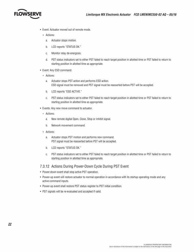
• Event: Actuator moved out of remote mode.
• Actions:
a. Actuator stops motion.
b. LCD reports “STATUS OK.”
c. Monitor relay de-energizes.
d. PST status indicators set to either PST failed to reach target position in allotted time or PST failed to return to starting position in allotted time as appropriate.
• Event: Any ESD command.
• Actions:
a. Actuator stops PST action and performs ESD action. ESD signal must be removed and PST signal must be reasserted before PST will be accepted.
b. LCD reports “ESD ACTIVE.”
c. PST status indicators set to either PST failed to reach target position in allotted time or PST failed to return to starting position in allotted time as appropriate.
• Events: Any new move command to actuator.
• Actions:
a. New remote digital Open, Close, Stop or Inhibit signal.
b. Network movement command.
• Actions:
a. Actuator stops PST motion and performs new command. PST signal must be reasserted before PST will be accepted.
b. LCD reports “STATUS OK.”
c. PST status indicators set to either PST failed to reach target position in allotted time or PST failed to return to starting position in allotted time as appropriate.
7.3.12 Actions During Power-Down Cycle During PST Event• Power-down event shall stop active PST operation.
• Power-up event will restore actuator to normal operation in accordance with its startup operating mode and any active command inputs.
• Power-up event shall restore PST status register to PST initial condition.
• PST signals will be re-evaluated and accepted if valid.
23
Limitorque MX Electronic Actuator FCD LMENIM2350-02 AQ – 05/16
flowserve.comFLOWSERVE PROPRIETARY INFORMATIONUse or disclosure of this information is subject to the restrictions on the title page of this document
8 Safety Instrumented System (SIS) Assessment
The actuator is a type B product that is fit for function in SIS that may require Safety Integrity Levels 2 or 3.
All Safety Instrumented Functions may be employed for SIL2 and SIL3 SIS (see section 5 Limitorque MXa Safety Instrumented Functions [SIF]).
a CAUTION: It is the responsibility of the SIL design engineer to carry out an overall SIL calculation for any Safety Instrumented System for which a Limitorque SIL rated actuator may be incorporated.
When SIL2 is required, then a single actuator may be employed in a single, one out of one configuration with a Hardware Fault Tolerance = 0. ( See section 6 MXa Safety for an example of how deployment of an MXa actuator could affect the SIL capability of a SIF)
When SIL3 is required, then two actuators may be employed with a Hardware Fault Tolerance = 1.
The SIL certificate and assessment report are public domain documents and should be reviewed by the SIL design engineer. These documents may be found on the internet at http://www.exida.com/index.php/resources/sael/.
Limitorque MX Electronic Actuator FCD LMENIM2350-02 AQ – 05/16
24
FLOWSERVE PROPRIETARY INFORMATIONUse or disclosure of this information is subject to the restrictions on the title page of this document
9 CommissioningPlease read this manual in its entirety before attempting to install or operate your MXA actuator. A full understanding of the installation and operation options will assist you in installing the actuator in the most effective manner. Limitorque has designed the MXA actuator for long life even in the harshest environments. Flexible control and protection options are provided to ensure the actuator meets your requirements.
a CAUTION: Refer to the Instruction, Operation and Maintenance [IOM] manual for Limitorque MX Electronic Actuator, LMENIM2306.
The latest version of the IOM can be found on the Flowserve website at www.flowserve.com.
9.1 Internal Access Only via Terminal CompartmentTo install and commission the actuator, only the terminal compartment cover needs to be removed. Operating configu-ration can be performed without direct access to the internal electronic circuit boards.
a CAUTION: Disconnect all incoming power before opening any cover on the actuator. The user/operator must ensure that safe working practices are employed at all times and are in accordance with local or national standards that are enforced at the particular site.
a CAUTION: Removal of any cover, other than the terminal compartment cover, will invalidate the unit warranty. Exposure of actuator components to an environment that results in deterioration of internal components will also invalidate the unit’s warranty.
9.2 Conduits and Unused Conduit Entries to be SealedDuring final field installation, ensure that all cable entries are correctly sealed in accordance with national standards or regulatory authorities. All temporary transit plugs must be removed and any unused cable entries closed in an approved manner.
9.3 Cable and Wire RoutingPower and signal wiring need to be routed through separate conduit or raceways.
Flowserve strongly recommends remote communication wiring be routed separately from line power wiring. Specifically, instrumentation wiring, including communication, analog and discrete signal signals, should be routed in conduits or raceways that are separate from power wiring. Flowserve cannot guarantee the reliability of instrumentation signaling if this recommendation is not implemented.
25
Limitorque MX Electronic Actuator FCD LMENIM2350-02 AQ – 05/16
flowserve.comFLOWSERVE PROPRIETARY INFORMATIONUse or disclosure of this information is subject to the restrictions on the title page of this document
9.4 PST and PST/ESD Configuration
9.4.1 Basic ConfigurationThe basic PST/ESD configuration may be configured such that separate signals may be dedicated individually to PST and ESD functions. However, the enhanced PST and PST/ESD configuration employs redundant but logically opposite signals to enable PST and to release an ESD action. It also dedicates a single input that is to be used for both ESD and PST commands.
Note that by configuring ESD and PST actions to commence when a normally persistent signal is removed (action when signal not present), then the ESD or SIF action will automatically commence if the signal wires are destroyed during an emergency.
9.4.2 Enhanced ConfigurationEnhanced ESD/PST configuration and signal wiring (see 4.2.2), the user will be extending some of the built-in protection and redundancy features of the Limitorque actuator into the user’s signaling environment. Note that when requesting a PST on an actuator that has been so configured, the PST signal actually passes through the same signal wires as would the ESD signal. Thus, in addition to confirming the availability of the actuator to perform its safety function, the PST signal also confirms the functionality of the user’s ESD signaling equipment.
Note also that the enhanced configuration operates with a momentary ESD or PST signal (>800ms), thus enabling actuator to continue its preconfigured ESD action even if the signal wires are subsequently destroyed during the emergency.
9.4.3 Access LCD Menu / DialogueEnter the “SETUP” mode.
Move the red REMOTE-STOP-LOCAL knob to STOP.
Within 10 seconds, toggle the black OPEN-CLOSE knob:
→ OPEN (YES) → CLOSE (NO) → OPEN (Yes) → Release
Display:SETUP?
Within 10 seconds, toggle the black OPEN-CLOSE knob: → OPEN (Yes) → Release
Display:SETUP?
ENGLISH?
Select the dialogue language.
Toggle “NO” to cycle through the language options.
Select “YES” when the desired language appears on the LCD.
NOTE: Available languages are English (default), Mandarin, Spanish, German, Russian, French, Italian, Portuguese, Malay and Katakana.
Display:CHANGE
SETTINGS?
Within 15 minutes, Toggle the black OPEN-CLOSE knob: → OPEN (YES) → Release
Limitorque MX Electronic Actuator FCD LMENIM2350-02 AQ – 05/16
26
FLOWSERVE PROPRIETARY INFORMATIONUse or disclosure of this information is subject to the restrictions on the title page of this document
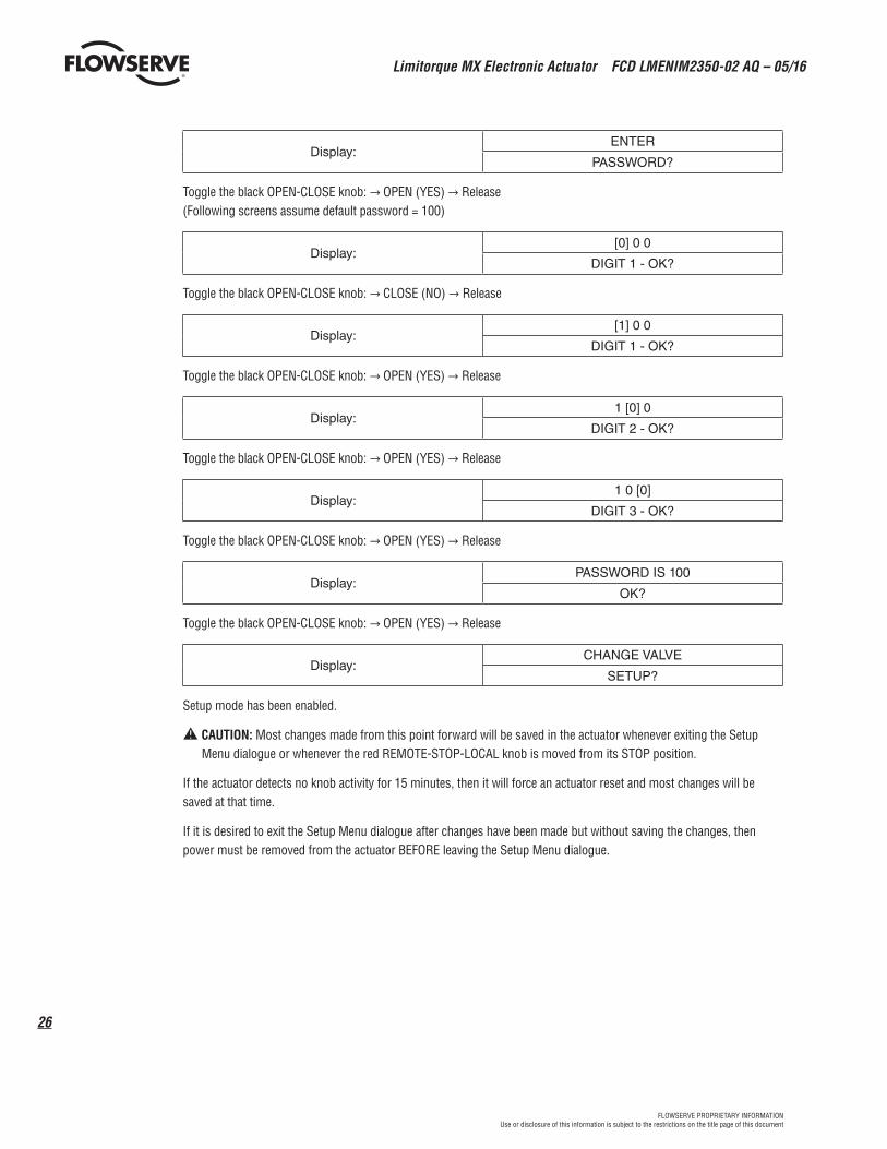
Display:ENTER
PASSWORD?
Toggle the black OPEN-CLOSE knob: → OPEN (YES) → Release (Following screens assume default password = 100)
Display:[0] 0 0
DIGIT 1 - OK?
Toggle the black OPEN-CLOSE knob: → CLOSE (NO) → Release
Display:[1] 0 0
DIGIT 1 - OK?
Toggle the black OPEN-CLOSE knob: → OPEN (YES) → Release
Display:1 [0] 0
DIGIT 2 - OK?
Toggle the black OPEN-CLOSE knob: → OPEN (YES) → Release
Display:1 0 [0]
DIGIT 3 - OK?
Toggle the black OPEN-CLOSE knob: → OPEN (YES) → Release
Display:PASSWORD IS 100
OK?
Toggle the black OPEN-CLOSE knob: → OPEN (YES) → Release
Display:CHANGE VALVE
SETUP?
Setup mode has been enabled.
a CAUTION: Most changes made from this point forward will be saved in the actuator whenever exiting the Setup Menu dialogue or whenever the red REMOTE-STOP-LOCAL knob is moved from its STOP position.
If the actuator detects no knob activity for 15 minutes, then it will force an actuator reset and most changes will be saved at that time.
If it is desired to exit the Setup Menu dialogue after changes have been made but without saving the changes, then power must be removed from the actuator BEFORE leaving the Setup Menu dialogue.
27
Limitorque MX Electronic Actuator FCD LMENIM2350-02 AQ – 05/16
flowserve.comFLOWSERVE PROPRIETARY INFORMATIONUse or disclosure of this information is subject to the restrictions on the title page of this document
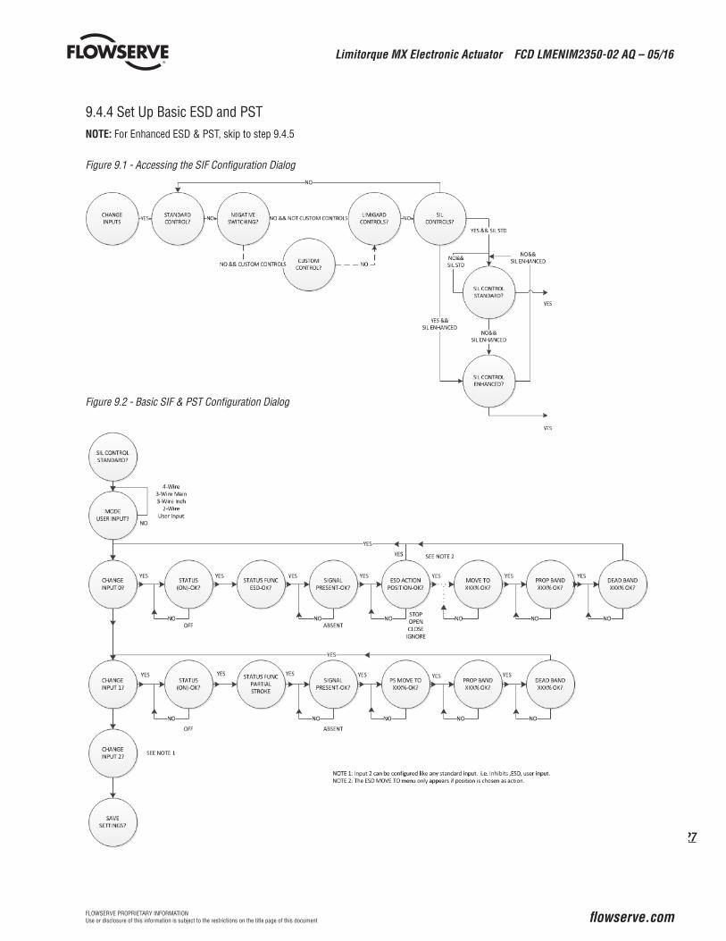
9.4.4 Set Up Basic ESD and PST NOTE: For Enhanced ESD & PST, skip to step 9.4.5
Figure 9.1 - Accessing the SIF Configuration Dialog
Figure 9.2 - Basic SIF & PST Configuration Dialog
Limitorque MX Electronic Actuator FCD LMENIM2350-02 AQ – 05/16
28
FLOWSERVE PROPRIETARY INFORMATIONUse or disclosure of this information is subject to the restrictions on the title page of this document
9.4.5 Set Up Enhanced ESD and PST
NOTE: Enhanced ESD and PST is a factory-enabled option that should be purchased with the actuator. It may be added to in-service actuators but service and acquisition fees will be applied.
NOTE: For other configuration options, refer to the Instruction, Operation and Maintenance [IOM] manual for Limitorque MX Electronic Actuator, LMENIM2306.
Limitorque MX Electronic Actuator FCD LMENIM2350-02 AQ – 05/16
flowserve.comFLOWSERVE PROPRIETARY INFORMATIONUse or disclosure of this information is subject to the restrictions on the title page of this document
10 Emergency Shutdown (ESD)
ESD signals may be applied to the actuator to override any existing command signal and send the valve to its pre-selected shutdown position, providing the actuator is in the remote mode.
Any non-ESD command signal will be ignored while the ESD signal is asserted.
10.1 Configurable ESD Actions• Open
• Close
• Stop
• Ignore (continue normal operation)
• Move to fail-safe position.
10.2 Configurable ESD Signal LogicSignal present (electrical signal assumed to be available during emergency).
Signal absent (electrical signal normally present but is removed during emergency by operations personnel or by failure in the remote wiring or equipment).
Limitorque MX Electronic Actuator FCD LMENIM2350-02 AQ – 05/16
30
FLOWSERVE PROPRIETARY INFORMATIONUse or disclosure of this information is subject to the restrictions on the title page of this document
10.3 Configurable ESD OverridesThe ESD action may also be configured to override the following:
• Inhibit signals.
• Local and Stop position of the Local-Stop-Remote selector switch.
• Over-torque or valve jammed protection.
• Lost phase protection.
• Motor thermal protection.
c WARNING: Disabling the motor over-temperature, valve jammed or over-torque protection features are permitted, but by doing so, the user chooses to void the Flowserve warranty and all third-party certifications, including Factory Mutual, CSA, IECex and ATEX.
10.4 Remote External Interlocks/InhibitsThree user-defined inputs are provided for the connection of remote contacts that may be used to prevent motorized operation of the actuator.
These are effective in both remote and local modes and may be overridden by an ESD signal, if so configured.
10.5 Custom Input Mode – Momentary ESD/PSESD (Optional)The following menus will appear if the customer has the custom mode input option and has enabled custom mode 1 (in remote control menu).
For custom mode input option and has enabled custom mode 1:
Figure 10.1 - Change Inputs
Following are the preconfigured settings for each input.
Input 0: off, user input, signal present
Input 1: off, PS/ESD enable, signal present
Input 3: on, momentary ESD release, signal present
Input 4, on, momentary ESD release, signal present
Input 5: on, momentary ESD/PSESD, signal present, ESD action close, PS move to target 0%
see Note 4 see Note 5 see Note 6
Note 4: The “ESD ACTION” menu will only appear if the status function for the input is “MOMENTARY ESD/PSESD”. Otherwise the “SIGNAL PRESENT” menu will return to the “CHANGE INPUTS” menu.
Note 5: The “ESD MOVE TO” menu only appears if position is chosen as action .
Note 6: “PS MOVE TO” menu only appears if the status function of the input is “MOMENTARY ESD/PSESD”.
The user will only be able to change the ESD ACTION (and ESD MOVE TO target if ESD action is position, and the PS MOVE TO settings when in this special custom mode 1.Following are the preconfigured settings for each input.
INPUT 0: ON, ESD Time Delay Relay, signal present, ESD action closed.INPUT 1: ON, User Input, signal presentINPUT 2: ON, User Input, signal presentINPUT 3: ON, StopINPUT 4: ON, OpenINPUT 5: ON, Close
The following menus will appear if the customer has the custom mode input option, and has enabled custom mode 1 (in remote control menu). Custom mode 2 is same as mode 1 except there is no PS sequence available. See Table 4.1.
CHANGEINPUTS?
CHANGE INPUT 0?
STATUS(ON) - OK?
INPUT (1)INPUT (2)
(CLOSE INHIBIT)(OPEN INHIBIT)(BOTH INHIBIT)(USER INHIBIT) - See Note 1
(OFF)
STATUS FUNCTION ESD - OK?
Note 1: ESD is hard oded for INPUT 0. You can only configure INPUTS 1 and 2 for the other options.Note 2: TDR DELAY will only show for INPUT 0. All other inputs this is skipped.Note 3: ESD ACTION menu will only appear if the STATUS FUNCTION for inputs is ESD otherwise the SIGNAL PRESET menu will return to the CHANGE INPUTS menu.Note 4: The ESD MOVE TO menu only appears if position is chosen as action.
YES
NONO
YES
NO
YES
NO
YES
INPUT 0: ON, ESD Time Delay Relay, signal present, ESD action closed.INPUT 1: ON, User Input, signal presentINPUT 2: ON, User Input, signal presentINPUT 3: ON, StopINPUT 4: ON, OpenINPUT 5: ON, Close
0-1800 SECS30 SEC INCREMENTS
TDR DELAY 0 SECS - OK?
YES
NO
See Note 2
See Note 3 See Note 4
ABSENT (IGNORE)(POSITION)(STOP)(OPEN)
SIGNAL(PRESENT)-OK?
ESD ACTION(CLOSE)-OK?
ESD MOVE TOXXX% OPEN
YES
NO
YES
NO
YES
NO
The following menus will appear if the customer has the custom mode input option, and has enabled custom mode 3 (in remote control menu).
31
Limitorque MX Electronic Actuator FCD LMENIM2350-02 AQ – 05/16
flowserve.comFLOWSERVE PROPRIETARY INFORMATIONUse or disclosure of this information is subject to the restrictions on the title page of this document
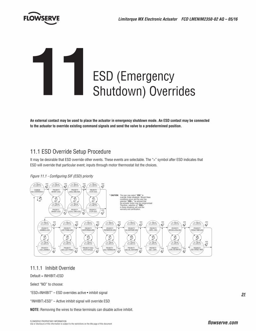
11 An external contact may be used to place the actuator in emergency shutdown mode. An ESD contact may be connected to the actuator to override existing command signals and send the valve to a predetermined position.
11.1 ESD Override Setup ProcedureIt may be desirable that ESD override other events. These events are selectable. The “>” symbol after ESD indicates that ESD will override that particular event; inputs through motor thermostat list the choices.
Figure 11.1 - Configuring SIF (ESD) priority
11.1.1 Inhibit OverrideDefault = INHIBIT>ESD
Select “NO” to choose:
“ESD>INHIBIT” – ESD overrides active • inhibit signal
“INHIBIT>ESD” – Active inhibit signal will override ESD
NOTE: Removing the wires to these terminals can disable active inhibit.
YES YES YES
NO
YES YES YES
YES
YES
YES
YES YES
YES YES YES
NO NO NO
NO NO NO NO
* * *
* CAUTION: The user may select “ESD” tooverride these situations. Should theseconditions occur and the user has selected “ESD> ,” be advised that the actuator motor may be compromisedTherefore, selection of “ESD>”in these situations will void thewarranty and certification.
*
CHANGEESD OVERRIDES?
PRIORITYINHIBIT>ESD
PRIORITYLOCAL CMD>ESD
PRIORITYSTOP>ESD
PRIORITYJAMMED>ESD
PRIORITYLOST PHASE>ESD
PRIORITYOVERTORQUE>ESD
PRIORITYINHIBIT<ESD
PRIORITYLOCAL CMD<ESD
PRIORITYSTOP<ESD
PRIORITYESD>JAMMED
PRIORITYESD>LOST PHASE
PRIORITY ESD>OVERTORQUE
PRIORITYNW ESD>LOCAL ESD
PRIORITY*
YES
YES
NO
PRIORITYTHERMOSTAT>ESD
PRIORITYESD>THERMOSTAT
*
YES
YES YES
NO
PRIORITY2SPD > ESD
PRIORITYESD > 2SPD
*LOCAL ESD>NW ESD
YES
YES
NO
PRIORITYOIL OVERTEMP>ESD
PRIORITYESD>OIL OVERTEMP
*
YES
YESNO
PRIORITYTORQUE TIMER>ESD
PRIORITYESD>TORQUE TIMER
ESD (Emergency Shutdown) Overrides
Limitorque MX Electronic Actuator FCD LMENIM2350-02 AQ – 05/16
32
FLOWSERVE PROPRIETARY INFORMATIONUse or disclosure of this information is subject to the restrictions on the title page of this document
11.1.2 Local Command OverrideDefault = LOCAL>ESD
Select “NO” to choose:
“ESD>LOCAL” – ESD overrides local command to operate actuator
“LOCAL>ESD” – Local command to operate actuator overrides ESD
“ESD>THERMOSTAT” – ESD overrides Motor Thermostat tripped
“THERMOSTAT>ESD” – Motor Thermostat tripped overrides ESD
NOTE: Disabling the motor thermostat voids all third-party certifications including Factory Mutual, CSA, IECex and ATEX. Disabling the motor thermostat removes protection from overheating the motor and may cause unsafe conditions.
33
Limitorque MX Electronic Actuator FCD LMENIM2350-02 AQ – 05/16
flowserve.comFLOWSERVE PROPRIETARY INFORMATIONUse or disclosure of this information is subject to the restrictions on the title page of this document
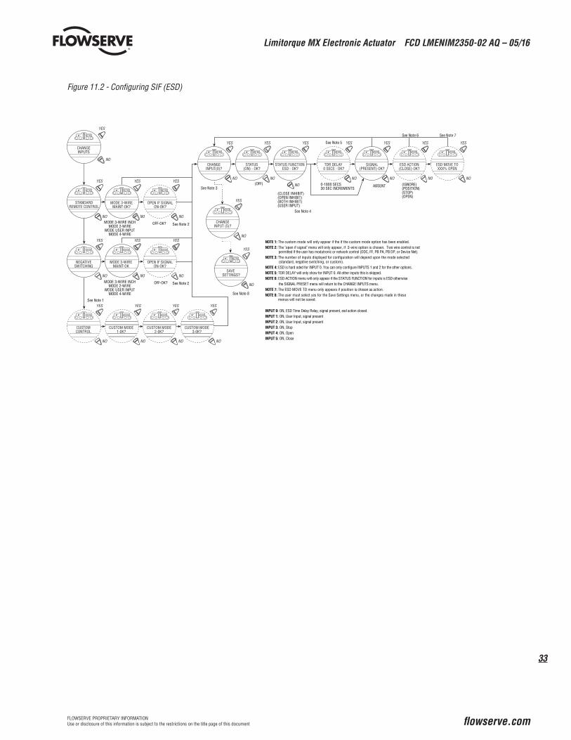
NOTE 1: The custom mode will only appear if the if the custom mode option has been enabled.NOTE 2: The "open if signal" menu will only appear, if 2-wire option is chosen. Two wire control is not permitted if the user has modutronic or network control (DDC, FF, PB PA, PB DP, or Device Net).NOTE 3: The number of inputs displayed for configuration will depend upon the mode selected (standard, negative switching, or custom).NOTE 4: ESD is hard oded for INPUT 0. You can only configure INPUTS 1 and 2 for the other options.NOTE 5: TDR DELAY will only show for INPUT 0. All other inputs this is skipped.NOTE 6: ESD ACTION menu will only appear if the STATUS FUNCTION for inputs is ESD otherwise the SIGNAL PRESET menu will return to the CHANGE INPUTS menu.NOTE 7: The ESD MOVE TO menu only appears if position is chosen as action.NOTE 8: The user must select yes for the Save Settings menu, or the changes made in these menus will not be saved.
INPUT 0: ON, ESD Time Delay Relay, signal present, esd action closed.INPUT 1: ON, User Input, signal presentINPUT 2: ON, User Input, signal presentINPUT 3: ON, StopINPUT 4: ON, OpenINPUT 5: ON, Close
See Note 1
MODE 3-WIRE INCHMODE 2-WIRE
MODE USER INPUTMODE 4-WIRE
See Note 2
See Note 2
See Note 8
MODE 3-WIRE INCHMODE 2-WIRE
MODE USER INPUTMODE 4-WIRE
CHANGEINPUTS
STANDARDREMOTE CONTROL
NEGATIVESWITCHING
MODE 3-WIREMAINT-OK
MODE 3-WIREMAINT-OK?
CHANGEINPUT(0)?
STATUS(ON) - OK?
STATUS FUNCTION ESD - OK?
TDR DELAY 0 SECS - OK?
SIGNAL(PRESENT)-OK?
SAVE SETTINGS?
ESD ACTION(CLOSE)-OK?
ESD MOVE TOXXX% OPEN
OPEN IF SIGNALON-OK?
CUSTOMCONTROL
CUSTOM MODE1-0K?
CUSTOM MODE2-0K?
CUSTOM MODE3-0K?
OPEN IF SIGNALON-OK?
CHANGEINPUT (5)?
YES
NO
YES
NO
YES
NO
YES
NO
YES
NO
YES
NO
YES
NO
YES
NO
YES
NO
YES
NO
YES
NO
YES
NO
YES
NO
YES
NO
YES
NO
YES
NO
YES
NO
YES
NO
YES
NO
YES
NO
Limitorque MX Electronic Actuator FCD LMENIM2350-02 AQ – 05/16
34
FLOWSERVE PROPRIETARY INFORMATIONUse or disclosure of this information is subject to the restrictions on the title page of this document
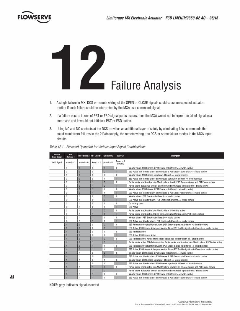
12 Failure Analysis
1. A single failure in MX, DCS or remote wiring of the OPEN or CLOSE signals could cause unexpected actuator motion if such failure could be interpreted by the MXA as a command signal.
2. If a failure occurs in one of PST or ESD signal paths occurs, then the MXA would not interpret the failed signal as a command and it would not initiate a PST or ESD action.
3. Using NC and NO contacts at the DCS provides an additional layer of safety by eliminating false commands that could result from failures in the 24Vdc supply, the remote wiring, the DCS or some failure modes in the MXA input circuits.
Table 12.1 - Expected Operation for Various Input Signal Combinations
1 0 1 1 0 ESD Release Active plus Monitor Alarm (PST Enable signals not different => invalid combo)
1 0 1 1 1 ESD Active, ESD Release Active plus Monitor Alarm (PST Enable signals not different => invalid combo)
1 1 0 0 0 Monitor alarm (ESD Release & PST Enable not different => invalid combo)
1 1 0 0 1 ESD Active plus Monitor alarm (ESD Release & PST Enable not different => invalid combo)
1 1 0 1 0 Monitor alarm (ESD Release signals not different => invalid combo)
1 1 0 1 1 ESD Active plus Monitor alarm (ESD Release signals not different => invalid combo)
1 1 1 0 0 Partial stroke enable active plus Monitor alarm (invalid ESD Release signals and PST Enable active)
1 1 1 0 1 Partial stroke active plus Monitor alarm (invalid ESD Release signals and PST Enable active)
1 1 1 1 0 Monitor alarm (ESD Release & PST Enable not different => invalid combo)
1 1 1 1 1 ESD Active plus Monitor alarm (ESD Release & PST Enable not different => invalid combo)
NOTE: gray indicates signal asserted
Failure Analysis
35
Limitorque MX Electronic Actuator FCD LMENIM2350-02 AQ – 05/16
flowserve.comFLOWSERVE PROPRIETARY INFORMATIONUse or disclosure of this information is subject to the restrictions on the title page of this document
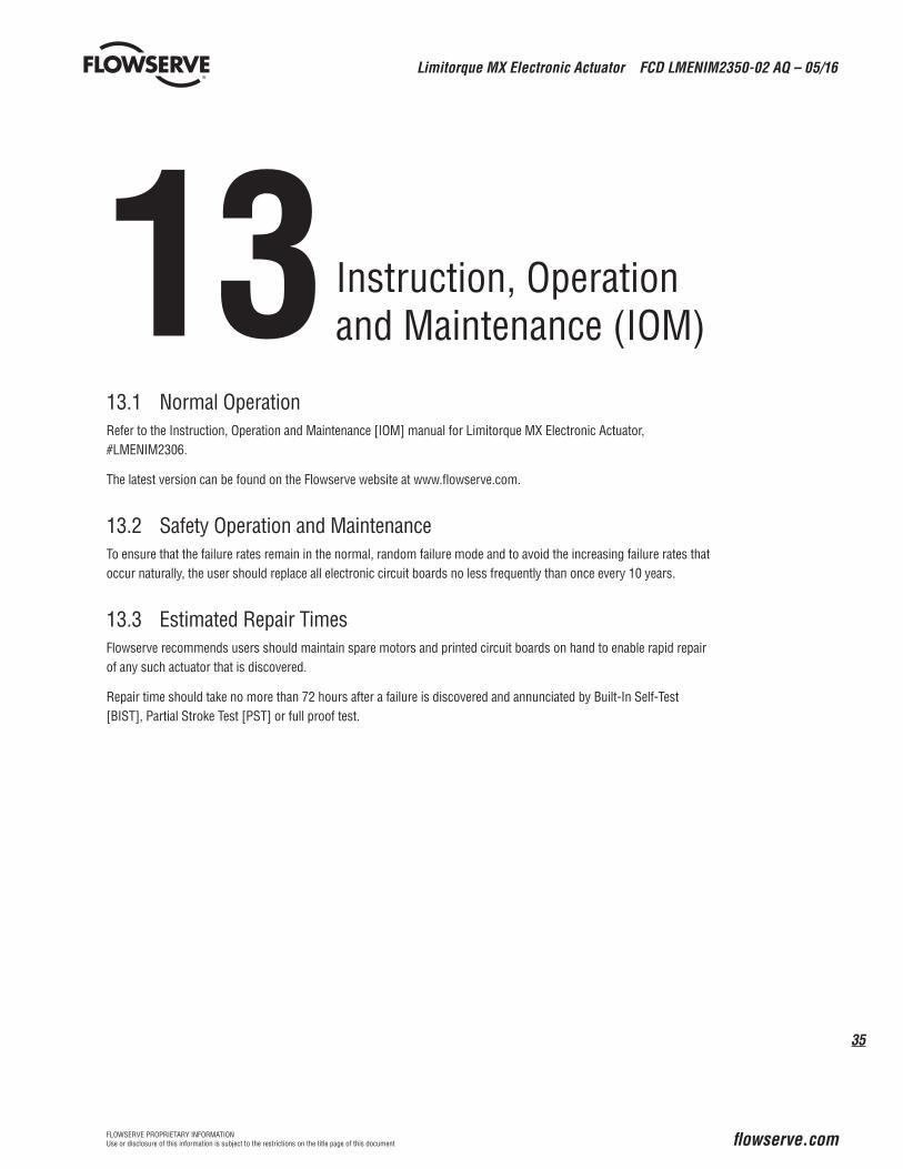
13 13.1 Normal OperationRefer to the Instruction, Operation and Maintenance [IOM] manual for Limitorque MX Electronic Actuator, #LMENIM2306.
The latest version can be found on the Flowserve website at www.flowserve.com.
13.2 Safety Operation and MaintenanceTo ensure that the failure rates remain in the normal, random failure mode and to avoid the increasing failure rates that occur naturally, the user should replace all electronic circuit boards no less frequently than once every 10 years.
13.3 Estimated Repair TimesFlowserve recommends users should maintain spare motors and printed circuit boards on hand to enable rapid repair of any such actuator that is discovered.
Repair time should take no more than 72 hours after a failure is discovered and annunciated by Built-In Self-Test [BIST], Partial Stroke Test [PST] or full proof test.
Instruction, Operationand Maintenance (IOM)
Limitorque MX Electronic Actuator FCD LMENIM2350-02 AQ – 05/16
36
FLOWSERVE PROPRIETARY INFORMATIONUse or disclosure of this information is subject to the restrictions on the title page of this document
14Revision Date Description
1.2 12 Jan 2012 Initial Release
1.3 13 Apr 2012 Added SIS assessment section
1.4 7 May 2012 Revised section 8
2.2 24 April 2013 General revision for submittal to cover inclusion of option boards
2.3/2.4 1 June 2013 Modified sections 6, 8 to include example for assessment
2.5 7 June 2013 Modified to match actual operation:
Deleted Figure 8 (superfluous; info held in Figures 5 & 7)
Deleted section 6.5 (Custom Input mode)
2.6 8 April 2016 Added network boards, HART and Profibus PA
Revision History
37
Limitorque MX Electronic Actuator FCD LMENIM2350-02 AQ – 05/16
flowserve.comFLOWSERVE PROPRIETARY INFORMATIONUse or disclosure of this information is subject to the restrictions on the title page of this document
15 Regulatory Information
15.1 Certification that adds HART network option board with up to SIL3 capable rating
Limitorque MX Electronic Actuator FCD LMENIM2350-02 AQ – 05/16
38
FLOWSERVE PROPRIETARY INFORMATIONUse or disclosure of this information is subject to the restrictions on the title page of this document
39
Limitorque MX Electronic Actuator FCD LMENIM2350-02 AQ – 05/16
flowserve.comFLOWSERVE PROPRIETARY INFORMATIONUse or disclosure of this information is subject to the restrictions on the title page of this document
15.2 Original certification that added option boards with up to SIL3 capable rating
Limitorque MX Electronic Actuator FCD LMENIM2350-02 AQ – 05/16
40
FLOWSERVE PROPRIETARY INFORMATIONUse or disclosure of this information is subject to the restrictions on the title page of this document
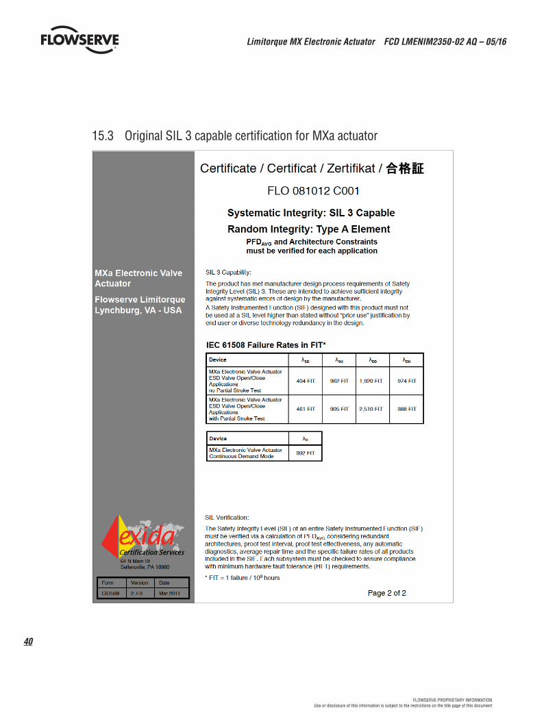
15.3 Original SIL 3 capable certification for MXa actuator
41
Limitorque MX Electronic Actuator FCD LMENIM2350-02 AQ – 05/16
flowserve.comFLOWSERVE PROPRIETARY INFORMATIONUse or disclosure of this information is subject to the restrictions on the title page of this document
This page left blank intentionally.
Limitorque MX Electronic Actuator FCD LMENIM2350-02 AQ – 05/16
42
FLOWSERVE PROPRIETARY INFORMATIONUse or disclosure of this information is subject to the restrictions on the title page of this document
This page left blank intentionally.
43
Limitorque MX Electronic Actuator FCD LMENIM2350-02 AQ – 05/16
flowserve.comFLOWSERVE PROPRIETARY INFORMATIONUse or disclosure of this information is subject to the restrictions on the title page of this document
This page left blank intentionally.
flowserve.com
To find your local Flowserve Limitorque representative: Visit www.flowserve.com/limitorque or call 1-434-528-4400
Flowserve Corporation has established industry leadership in the design and manufacture of its products. When properly selected, this Flowserve product is designed to perform its intended function safely during its useful life. However, the purchaser or user of Flowserve products should be aware that Flowserve products might be used in numerous applications under a wide variety of industrial service conditions. Although Flowserve can (and often does) provide general guidelines, it cannot provide specific data and warnings for all possible applications. The purchaser/user must therefore assume the ultimate responsibility for the proper sizing and selection, installation, operation, and maintenance of Flowserve products. The purchaser/user should read and understand the Installation Operation Maintenance (IOM) instructions included with the product, and train its employees and contractors in the safe use of Flowserve products in connection with the specific application.
While the information and specifications contained in this literature are believed to be accurate, they are supplied for informative purposes only and should not be considered certified or as a guarantee of satisfactory results by reliance thereon. Nothing contained herein is to be construed as a warranty or guarantee, express or implied, regarding any matter with respect to this product. Because Flowserve is continually improving and upgrading its product design, the specifications, dimensions and information contained herein are subject to change without notice. Should any question arise concerning these provisions, the purchaser/user should contact Flowserve Corporation at any one of its worldwide operations or offices.