52

// D
RIL
LIN
G A
ND
CO
RIN
G T
OO
LS
, A
CC
ES
SO
RIE
S
71
INSTRUCTIONS FOR USING THE AUGERS
CONCERNED TO IMPROVE OUR PRODUCTS AND THE SAFETY OF PEOPLE, WE GIVE YOU SOME ADVICE AND RECOMMENDATIONS ON HOW TO USE THE AUGER.
Using the auger, continuous screw auger, hollow stem auger, or injection auger under unsuitable conditions may cause serious or even fatal accidents.All our augers are manufactured in France in our factories according to current manufacturing standards and best practices. They guarantee you the highest productivity for your work-sites in perfect safety. Consult us if you have a question on this tool’s use.
YOU MUST
• Make sure every auger is in perfect condition before use
• Use an auger guide on your drilling rig
• Use suitable boring parameters: rotation torques, rotation speed, and pressure on bit depending on the auger diameter
• Your auger drive shafts have to have bellows
YOU MUST NOT IN ANY CASE
• Approach this tool while boring (danger of entanglement)
• Clean the tools by hand (danger of entanglement)
• Use the tool in case of excessive or irregular wear, twisted bore, or damaged or interrupted thread etc...
72
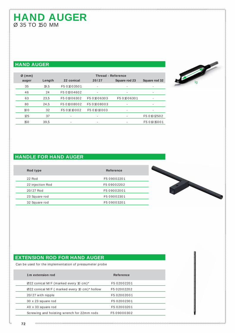
HAND AUGER
Ø (mm) Thread - Reference
auger Length 22 conical 20/27 Square rod 23 Square rod 32
35 19,5 F5 01003501 - - -
46 24 F5 01004602 - - -
63 23,5 F5 01006302 F5 01006303 F5 01006301 -
80 24,5 F5 01008002 F5 01008003 - -
100 32 F5 01010002 F5 01010003 - -
125 37 - - - F5 01012502
150 39,5 - - - F5 01015001
EXTENSION ROD FOR HAND AUGERCan be used for the implementation of pressumeter probe
1 m extension rod
Reference
Ø22 conical M/F (marked every 10 cm)* F5 02002201
Ø22 conical M/F ( marked every 10 cm)* hollow F5 02002202
20/27 with nipple F5 02002001
30 x 23 square rod F5 02002301
40 x 33 square rod F5 02003201
Screwing and hoisting wrench for 22mm rods F5 09000302
HAND AUGERØ 35 TO 150 MM
HANDLE FOR HAND AUGER
Rod type Reference
22 Rod F5 09002201
22 injection Rod F5 09002202
20/27 Rod F5 09002001
23 Square rod F5 09002301
32 Square rod F5 09003201
lg

73
// D
RIL
LIN
G A
ND
CO
RIN
G T
OO
LS
, A
CC
ES
SO
RIE
S
CONTINUOUS FLIGHT AUGERS
AUGER FOR PRESSUREMETER DRILLINGSRight rotation
Ø 63 mm Hex Core
Auger (mm) (mm) Reference
1,00 m length 21 25 F1 01006304
1,50 m length 21 25 F1 01006303
Left rotation
Ø 63 mm Hex Core
Auger (mm) (mm) Reference
1,00 m length 21 25 F1 01006305
1,50 m length 21 25 F1 01006306
CONTINUOUS FLIGHT AUGER Ø 63 MM TO Ø 254 MM
Ø auger Ø bit Core Hex Reference Reference
(mm) and hole (mm) (mm) 1,00 m length 1,50 m length
63 63 25 21 F1 01006307 F1 01006303
75 76 32 21 F1 01007500 F1 01007501
80 89 43 29 F1 01008001 F1 01008003
100 114 43 29 F1 01010003 F1 01010004
114 127 43 29 F1 01011401 F1 01011402
114 127 60 41 F1 01011404 F1 01011403
140 152 43 29 F1 01014001 F1 01014002
140 152 60 41 F1 01014006 F1 01014007
152 178 60 41 F1 01015202 F1 01015203
178 203 60 41 F1 01017811 F1 01017808
178 203 76 51 F1 01017812 F1 01017809
225 254 76 41 F1 01022504 F1 01022501
225 254 76 51 F1 01022505 F1 01022502
254 305 76 41 F1 01025400 F1 01025401
254 305 76 51 F1 01025404 F1 01025402
Other lengths available, please consult us.
Our augers are steel hardened
U-PIN
Hex Reference
Hex 21 F1 04002101
Hex 29 F1 04002901
Hex 41 F1 04004101
Hex 51 F1 04005101
LEN
GTH
CORE
D
See instructions for
using the augers, p 71

74
BITSAND ACCESSORIES
2 PRONG BITS (WITH BRAZER TUNGSTENE CARBIDE PLATES)
Ø Hex Right rotation Left rotation
(mm) (mm) references references
63 21 F1 02006301 F1 02006302
63 21 F1 02006310 (with pilot bit) > (Ref. Pilot bit = IB 0100015)
76 21 F1 02007601
89 29 F1 02008901
FINGER HEAD BIT
Ø 29 41 51
(mm) Hex Hex Hex
114 F1 02012700 * *
127 F1 02012701 F1 02012702 *
152 F1 02015203 F1 02015204 *
178 * F1 02017801 *
203 * F1 02020301 F1 02020302
254 * F1 02025401 F1 02025402
305 * F1 02030501 F1 02030502
Tungstene carbide insert F1 02090002
Single wedge Small size F1 02090005
Double wedge Small size F1 02090006
Double wedge Large size F1 02090011
*Please, consult us
DP ROCK HEAD BIT
Ø Hex
(mm) (mm) Reference
114 29 F1 02090018
152 29 F1 02090014
152 41 F1 02090016
203 41 F1 02090021
203 51 F1 02090022
Small size inserts F1 02090019
Large size inserts F1 02090017

// D
RIL
LIN
G A
ND
CO
RIN
G T
OO
LS
, A
CC
ES
SO
RIE
S
BULLET HEAD BIT
Ø Hex
(mm) (mm) Reference
152 41 F1 02090207
203 41 F1 02090208
254 41 F1 02090209
254 51 F1 02090210
305 41 F1 02090211
305 51 F1 02090212
BULLDOG HEAD BIT
Ø Hex
(mm) (mm) Reference
114 29 F1 02111401
114 41 F1 02111402
152 29 F1 02115200
152 41 F1 02115201
TC inserts F1 02190001
75
76
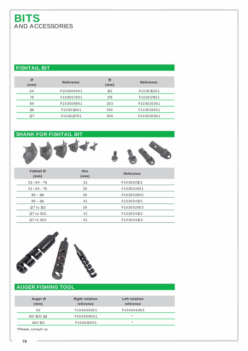
FISHTAIL BIT
Ø Ø
(mm) Reference
(mm) Reference
64 F1 03006401 152 F1 03015201
76 F1 03007601 178 F1 03017801
89 F1 03008901 203 F1 03020301
114 F1 03011401 254 F1 03025401
127 F1 03012701 305 F1 03030501
SHANK FOR FISHTAIL BIT
Fishtail Ø Hex
(mm) (mm) Reference
51 – 64 - 76 21 F1 03002101
51 – 64 - 76 29 F1 03002901
89 – 114 29 F1 03002902
89 – 114 41 F1 03004101
127 to 152 29 F1 03002903
127 to 305 41 F1 03004102
127 to 305 51 F1 03004103
AUGER FISHING TOOL
Auger Ø Right rotation Left rotation
(mm) reference reference
63 F1 04006301 F1 04006303
80/100/114 F1 04008001 *
140/152 F1 04014001 *
*Please, consult us
BITSAND ACCESSORIES
77
// D
RIL
LIN
G A
ND
CO
RIN
G T
OO
LS
, A
CC
ES
SO
RIE
S
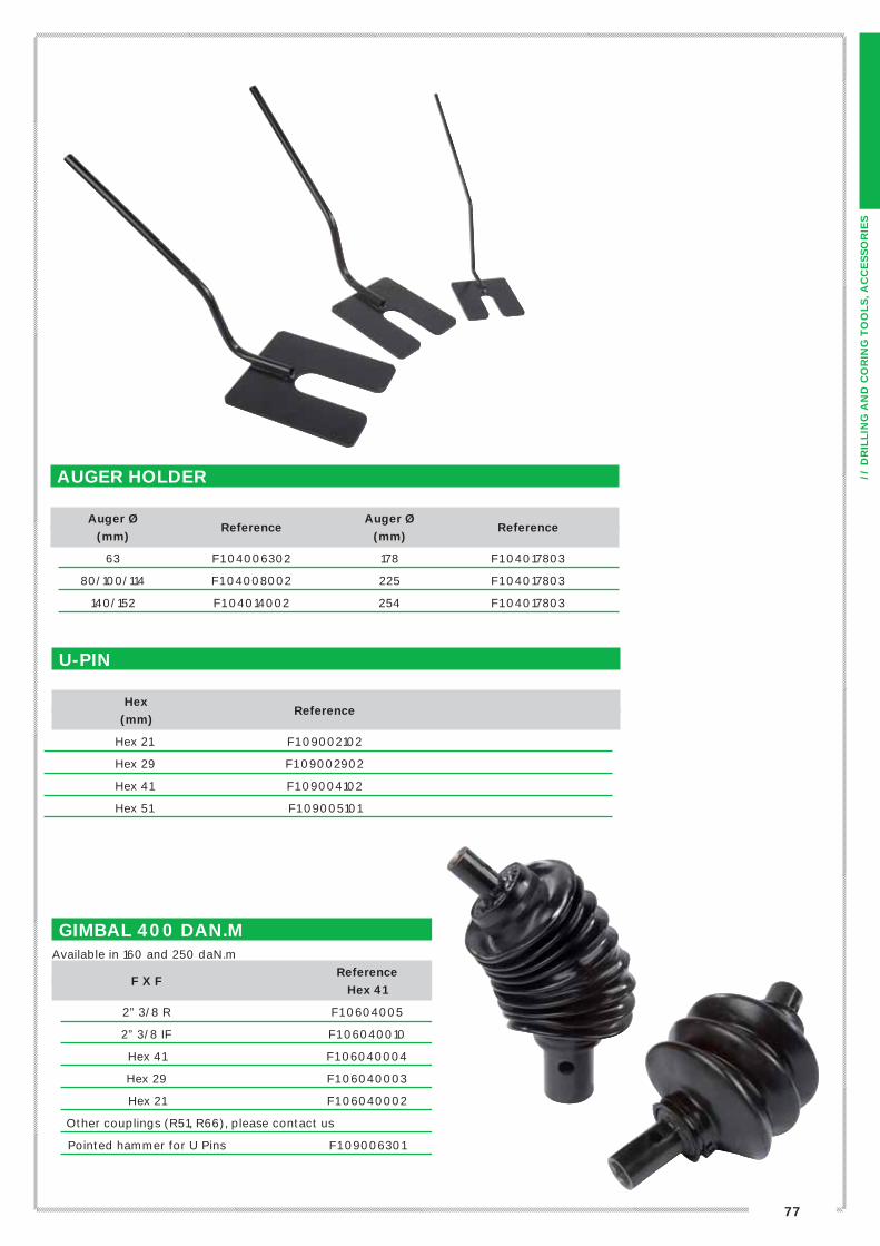
AUGER HOLDER
Auger Ø Auger Ø
(mm) Reference
(mm) Reference
63 F1 04006302 178 F1 04017803
80/100/114 F1 04008002 225 F1 04017803
140/152 F1 04014002 254 F1 04017803
U-PIN
Hex
(mm) Reference
Hex 21 F1 09002102
Hex 29 F1 09002902
Hex 41 F1 09004102
Hex 51 F1 09005101
GIMBAL 400 DAN.MAvailable in 160 and 250 daN.m
Reference
F X F
Hex 41
2” 3/8 R F1 0604005
2” 3/8 IF F1 06040010
Hex 41 F1 06040004
Hex 29 F1 06040003
Hex 21 F1 06040002
Other couplings (R51, R66), please contact us
Pointed hammer for U Pins F1 09006301

78
HOLLOW STEM AUGERS
PRINCIPLE
The hollow-stem auger (HSA) system is used to drill and case a borehole simultaneously in gravelly or heterogeneous soil such as sand or gravel.
The principle of this method is to use a string of rods with a pilot bit inside the auger string. The hollow-stem auger can also be positioned using lost tools instead of internal rods. Soil should not enter the auger regardless of the method used. This is an ideal method for piezometer installation, well monitoring, geotechnics, micro-piles, tubing for SPT tests and pressuremeter tests.
In a standard configuration (auger+rod), when the desired depth is reached, the inner rods are removed to free the inside of the auger. Coring or sampling is subsequently possible beyond this depth.
We offer a range of four standard dimensions identified by their inside and outside diameters:(ø inside x ø outside)• 66 x 140 mm (ø int x ø ext)• 82 x 175 mm (ø int x ø ext)• 111 x 194 mm (ø int x ø ext)• 159 x 254 mm (ø int x ø ext)
DESCRIPTION
The top of the equipment consists of a dual head leading both the auger string and the inner rod string. The augers are fixed to the driving head with nuts andbolts, whilst the top rod is fixed to the head using an adapter secured with a locking pin.
The augers and inner rods are added in 1.5 m lengths (or others lengths on request) until the target drilling depth is reached. The rods are threaded and screwed, whilst the augers are secured using nuts and bolts.
The first (bottom) rod is equipped with a plug adapter connecting the rod to the pilot bit. The bottom auger is fitted with a tungsten carbide cutter head bit including both self-sharpening bullets for chipping action and blades for cleaning.
When the inner rods are removed, the stem of the auger is completely emptied to its full inner diameter.

79
// D
RIL
LIN
G A
ND
CO
RIN
G T
OO
LS
, A
CC
ES
SO
RIE
SO
uti
ls e
t access
oir
es
de f
ora
ge
COMPOSITION OF THE SYSTEM
Dimensions in mm (Ø inside x Ø outside)
Description
Ø 66 x 140 Ø 82 x 175 Ø 111 x 194 Ø 159 x 254
1 Driving head F6 06614001 F6 08217501 F6 11119401 F6 15925401
2 Rod bolt * * * *
3 Rod x head adapter F6 06614004 F6 08217504 F6 11119404 F6 15925404
4 Auger locking bolt F6 06614010 F6 08217510 F6 11119410 F6 15925410
5 Hollow auger 1,5 m long F6 06614002 F6 08217502 F6 11119402 F6 15925402
6 Rod Ø60 x 1.5m K2 010006005 K2 010006005 K2 010006005
6 Rod Ø76 x 2’’3/8 Reg x 1.5m K2 010237505
7 Plug adapter for pilot bit F6 06614005 F6 08217505 F6 11119405 F6 15925405
8 Heavy duty cutter head bit F6 06614003 F6 08217503 F6 11119403 F6 15925403
9 Pilot bit Drag bit ø63,5 mm Drag bit ø76 mm Drag bit ø108 mm Drag bit ø156 mm ID 01025001 I5 010030001 I5 010042501 I5 010061251
10 Plug adapter for pilot bit * * * *
11 Finger bit * * * *
Left in hole bit (Option) F6 06614007 F6 08217507 F6 11119407 F6 15925407
ACCESSORIES Hoisting plug F6 06614009 F6 08217509 F6 11119409 F6 15925409
Auger holder F6 06614008 F6 08217508 F6 11119408 F6 15925408
Auger retriever F6 06614011 F6 08217511 F6 11119411 F6 15925412
*Please, consult us.
See instructions for
using the augers, p 71
OCTAGONAL CONNECTIONBEST REPARTITION OF DRILLING TORQUE AND
REDUCTION OF THE RISKS OF DAMAGE

80
INJECTION AUGERS « JET AUGER » TYPE
2 PRONG BIT FOR INJECTION AUGER
Ø auger Ø bit
(mm) (mm) Thread Reference
63 63 E F2 02006302
Other diameters: please, consult us
DP ROCK HEAD BIT
Ø auger Ø bit
(mm) (mm) Thread Reference
102 114 AWJ F1 02090100
114 127 60 F1 02090103
140 152 2”3/8 Reg F1 02090105
178 203 2”3/8 Reg F1 02090110
Small size inserts F1 02090019
Large size inserts F1 02090017
Other bits for injection augers: please, consult us
For cement grout injection, please consult our piston pumps.
INJECTION AUGER
Length 1.5 m
Ø (mm) Thread type Reference
63 E F2 01006302
102 AWJ F2 01010003
114 60 F2 01011401
140 2’’3/8 Reg F2 01014001
178 2’’3/8 Reg F2 01017802
225 2’’3/8 Reg F2 01022504
Other diameters and lengths: please, consult us
See instructions for
using the augers, p 71
LEN
GTH
DØ

81
// D
RIL
LIN
G A
ND
CO
RIN
G T
OO
LS
, A
CC
ES
SO
RIE
S
APAGEO offers a full range of rods, bits, shanks, adaptors and couplings for top hammer rotary percussion. We have a largestorage of material to meet your needs.Other threads can be manufactured: ask us for rods and bits in R22, R25, T38, T45 and T51.
RODS AND NIPPLESFOR TOP HAMMER ROTARY-PERCUSSION
RODS
Rod Thread Reference Reference
length R 32 rod R 38 rod
0.60 m MxM H1 02003204 H1 02003810
0.91 m MxM H1 02003205 H1 02003803
1,00 m MxF H1 02003215 -
1.22 m MxM H1 02003206 H1 02003804
1.52 m MxM H1 02003207 H1 02003801
1,52 m MxF H1 02003213 -
1.83 m MxM H1 02003208 H1 02003805
1,83 m MxF H1 02003214 -
2,00 m MxF H1 02003216 -
2.43 m MxM H1 02003209 H1 02003806
3.05 m MxM H1 02003210 H1 02003807
Nipple MxM H1 02003211 H1 02003808
Wrench MxM H1 09003201 H1 09003803
Fishing tool bell type MxM M7 0100020 M7 01000032
ADAPTOR AND COUPLING
R38 Fem R38 Male
R32 Fem H1 05003203 H1 05003803
R32 Male H1 05003207 H1 05003807
SPECIAL RODS AND SHANK
Description Reference
R38 M x M Rod guide– ø60 mm – lg 910 mm
(Stabilisor for pressuremeter tests) H1 02004001
R38 F x F wing guide sleeve ø60 mm - lg 190 mm H4 01000770
Shank for APAFOR 48 / 51 - R38 U4 7400503
Shank BBC 100 – R32 – side inj. H1 03003213
Shank BBC 120 – R32 – central inj. H1 03003810
Shank for Sed 350 U0 1900502
Shank GEO 205 H1 03003215
Shank GEO 305 H1 03003217

82
Ø Cross Retrac cross Button Retrac Rotary
Filetage
(mm) bits bits bits button bits 2 wings bits
R 32 43 - - H1 01204401 - -
oR 45 H1 01104501 H1 01204501 - -
1’’1/4 48 H1 01104801 - H1 01204801 - -
51 H1 01105100 H1 01105101 H1 01205101 H1 01205102 -
57 H1 01105701 - H1 01205701 H1 01205704 -
60 H1 01106002 H1 01106001 H1 01206001 H1 01206002 -
64 H1 01106404 H1 01106402 H1 01206401 H1 01206404 H1 01006301
66 H1 01106601 H1 01106602 H1 01206601 H1 01206604 H1 01006601
68 H1 01106801 H1 0116805 H1 01206803 H1 01206802 -
70 H1 01107101 H1 0117104 H1 01207001 H1 01207005 -
76 H1 01107601 H1 01107602 H1 01207601 H1 01207602 -
89 H1 01108901 H1 01108902 H1 01208901 H1 01208902 -
102 H1 01110203 H1 01110200 H1 01210201 H1 01210204 -
115 H1 01111500 - - - -
127 - - H1 01212703 H1 01212704 -
R 38 57 H1 01105702 - H1 01205703 - -
oR 64 H1 01106403 H1 01106405 H1 01206402 H1 01206403 H1 01006303
1’’1/2 66 H1 01106603 H1 01106604 H1 01206602 H1 01206603 H1 01006602
68 H1 01106802 H1 01106804 H1 01206800 H1 01206801 -
70 H1 01107102 H1 01107103 H1 01207002 H1 01207003 -
76 H1 01107603 H1 01107604 H1 01207603 H1 01207604 H1 01007601
89 H1 01108903 H1 01108904 H1 01208903 H1 01208904 -
102 H1 01110201 H1 01110202 H1 01210202 H1 01210203 -
115 H1 01111501 H1 01111502 H1 01211501 H1 01211502 -
127 H1 01112701 - H1 01212701 H1 01212702 -
152 - - H1 01215201 - -
Please contact us for bits in R25, BT 38 (1’’1/2), BT 45 (1’’3/4), BT 51 (2’’).
ROTARY-PERCUSSIONBITS

83
// D
RIL
LIN
G A
ND
CO
RIN
G T
OO
LS
, A
CC
ES
SO
RIE
S
APAGEO offers a full range of DTH hammers, as well as bits. Technical specifications below will help you tochoose the right equipment for boring. For each hammer, we recommend specific bit diameter, but we can also provide larger ones.
Hammer 1" 2" 3" 4" 5" 6" 8"
Reference H3 01001305 H3 01001306 H3 01120005 H3 01120010 H3 01120020 H3 0113006 H3 0113008
Shank type BR1 BR2 DHD 3.5 COP44/ DHD340 COP54/ DHD350 SD6 SD8
Thread RD 40 Fem RD 50 Fem 2’’3/8 Reg 2’’3/8 Reg 3’’1/2 Reg 3’’1/2 Reg 4’’1/2 Reg
Length (mm) 724 828 930 1030 1170 1264 1458
Outer Ø (mm) 50 62 81 99 125 142 180
Weight (kg) 8 13 24.50 39.2 71.5 97.5 194
Bit Ø (mm) 60-66 70-76-80 90-105 105-135 135-155 155-205 195-330
Air pressure (bar) 7 to 20 7 to 17 5 to 25 5 to 25 5 to 25 5 to 25 5 to 25
Air consumption (m3/min) 1,1 to 5,6 2 to 6,8 5 to 12,5 6 to 15 8,7 to 23,40 10,6 to 28,5 11,4 to 29,7
Rotary speed (rpm) 20 to 30 20 to 30 20 to 30 25 to 40 20 to 30 15 to 25 15 to 20
Shank
bit Ø (mm) 1" 2" 3" 4" 5" 6" 8"
64 H3 02206401
66 H3 02206601
70 H3 02207001
76 H3 02007601
80 H3 02009501
90 H3 012200090
95 H3 02219501
105 H3 01210501 H3 01220105
115 H3 01220100
127 H3 02012701
140 H3 01220140 H3 01220200
152 H3 02015201 H3 012215201 H3 01230504
165 H3 012216500 H3 01230502
178 H3 01230509
190 H3 01230505
203 H3 01230508
216 H3 012 30506
240 H3 01224001
254 H3 01230507
Other bits (other diameters and shank) are also available, please contact us.
DOWN THE HOLE HAMMERS AND BITS
Oil feeder for pneumaticequipment

84
STAREX®
OVERBURDEN DRILLING
200
mm
Ha
mm
er l
en
gth
Tub
e a
nd
sh
oe
len
gth
SG
Wing guide sleeve
Hammer
Welded casing shoe
Shoe
Guide
The STAREX® is an overburden drilling system enabling simultaneous drilling and casing in different types of formations.
This system is made up of a guide, a reamer and a pilot bit. It is used to drill a hole slightly larger than the external diameter of the casing. This enables the casing tube to follow the pilot bit down the hole without rotation.
The STAREX® series 76 and 90 casings are designed for simultaneous drilling and casing operated with top hammer. In the case of a DTH hammer-operated drilling, series 90 to 240 are to be used. On reaching the target depth, reverse rotation is applied which allowsthe eccentric reamer to turn in, thus reduced to its smallest diameter. It is then possible to pull up the drill string and leave the casing in place in the soil. Drilling can also continue in the available diameter at the foot of the casing.
STAREX® CASINGS DIMENSIONS
Starex® D Wall Thickness ID
casing types (mm) (mm) (mm) Thread g
TH 76 88,9 5,5 77,8 Right 60 / 70
TH/TDH 90 114,3 6,35 101,5 TH Right / DTH Left 60 / 70
DTH 115 139,7 6,35 127,0 Left 60 / 70
DTH 140 173,0 8,0 157,0 Left 60 / 70
DTH 165 193,7 6,6 180,5 Left 60 / 70
DTH 190 219,0 7,0 205,0 Left 70
DTH 240 285,0 12,0 261,0 Left 120
STAREX® TECHNICAL SPECIFICATIONS
Starex® Ø pilot Ø reamer Connection DTH Suitable
types (mm) (mm) thread hammer* drill rods
TH 76 70 96 R 38 female - Rod R38
TH 90 90 123 R 38 female - Rod R38
DTH 90 90 123 DHD 3.5 3’’ – DHD 3.5 76 / 89
DTH 115 115 152 COP 44/ DHD 340 4’’ – COP 44 / DHD 340 89
DTH 140 140 181 DHD 350 5’’ – DHD 350 114
DTH 165 165 209 SD6 6’’ – SD6 114
DTH 190 190 237 SD6 6’’ – SD6 114
DTH 240 240 306,5 SD8 8’’ – SD8 114
*Adaptable on all our STAREX® tools
STAREX®
SHOE WELDED CASING LENGTH DEFINITION:LENGTH (LTS) = S + G + LM – 200 MM
S = Shoe total length (depen-ding on model used)
G = Guide skirt length (manu-facturer specifications)
LM = Hammer length (manu-facturer specifications)
85
// D
RIL
LIN
G A
ND
CO
RIN
G T
OO
LS
, A
CC
ES
SO
RIE
S
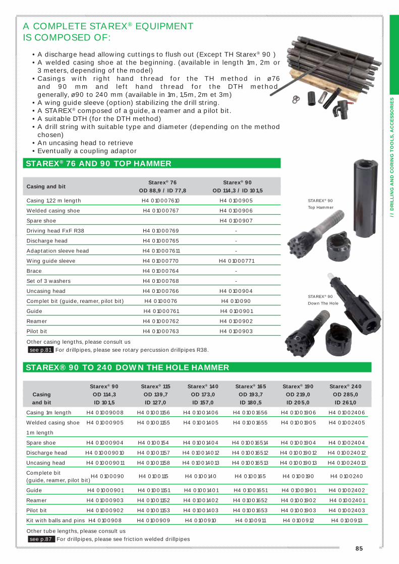
A COMPLETE STAREX® EQUIPMENT IS COMPOSED OF:
• A discharge head allowing cuttings to flush out (Except TH Starex® 90 )• A welded casing shoe at the beginning. (available in length 1m, 2m or
3 meters, depending of the model)• Casings with right hand thread for the TH method in ø76
and 90 mm and left hand thread for the DTH method, generally, ø90 to 240 mm (available in 1m, 1,5m, 2m et 3m)
• A wing guide sleeve (option) stabilizing the drill string.• A STAREX® composed of a guide, a reamer and a pilot bit.• A suitable DTH (for the DTH method)• A drill string with suitable type and diameter (depending on the method
chosen)• An uncasing head to retrieve• Eventually a coupling adaptor
STAREX® 76 AND 90 TOP HAMMER
Starex® 76 Starex® 90 Casing and bit
OD 88,9 / ID 77,8 OD 114,3 / ID 101,5
Casing 1,22 m length H4 010007610 H4 0100905
Welded casing shoe H4 01000767 H4 0100906
Spare shoe H4 0100907
Driving head FxF R38 H4 01000769 -
Discharge head H4 01000765 -
Adaptation sleeve head H4 010007611 -
Wing guide sleeve H4 01000770 H4 01000771
Brace H4 01000764 -
Set of 3 washers H4 01000768 -
Uncasing head H4 01000766 H4 0100904
Complet bit (guide, reamer, pilot bit) H4 0100076 H4 010090
Guide H4 01000761 H4 0100901
Reamer H4 01000762 H4 0100902
Pilot bit H4 01000763 H4 0100903
Other casing lengths, please consult us
see p.81 For drillpipes, please see rotary percussion drillpipes R38.
STAREX® 90 TO 240 DOWN THE HOLE HAMMER
Starex® 90 Starex® 115 Starex® 140 Starex® 165 Starex® 190 Starex® 240
Casing OD 114,3 OD 139,7 OD 173,0 OD 193,7 OD 219,0 OD 285,0
and bit ID 101,5 ID 127,0 ID 157,0 ID 180,5 ID 205,0 ID 261,0
Casing 1m length H4 01009008 H4 01001156 H4 01001406 H4 01001656 H4 01001906 H4 01002406
Welded casing shoe H4 01000905 H4 01001155 H4 01001405 H4 01001655 H4 01001905 H4 01002405
1 m length
Spare shoe H4 01000904 H4 0100154 H4 01001404 H4 010016514 H4 01001904 H4 01002404
Discharge head H4 010009010 H4 01001157 H4 010014012 H4 010016512 H4 010019012 H4 010024012
Uncasing head H4 010009011 H4 01001158 H4 010014013 H4 010016513 H4 010019013 H4 010024013
Complete bit
(guide, reamer, pilot bit) H4 0100090 H4 0100115 H4 0100140 H4 0100165 H4 0100190 H4 0100240
Guide H4 01000901 H4 01001151 H4 01001401 H4 01001651 H4 01001901 H4 01002402
Reamer H4 01000903 H4 01001152 H4 01001402 H4 01001652 H4 01001902 H4 01002401
Pilot bit H4 01000902 H4 01001153 H4 01001403 H4 01001653 H4 01001903 H4 01002403
Kit with balls and pins H4 0100908 H4 0100909 H4 0100910 H4 0100911 H4 0100912 H4 0100913
Other tube lengths, please consult us
see p.87 For drillpipes, please see friction welded drillpipes
STAREX® 90
Top Hammer
STAREX® 90
Down The Hole

86
Casing diameter: Ø in x Ø out (boring Ø) in mm
Description
Ø 67 x 74 (86) Ø 76.2 x 88.9 (101) Ø 104 x 113 (125)
1 Driving nipple H5 0067109 H5 0076109 H5 0100109
2 Driving ring H5 0067101 H5 0076101 H5 0100101
3 Casing driving head H5 0067102 H5 0076102 H5 0100102
4 Casing lg 1.22m H5 0067105 H5 0076105 H5 0100105
5 R32 rod lg 1.22m H1 02003206 - -
5 R38 rod lg 1.22m - H1 02003804 H1 02003804
6 R32 nipple H1 02003211 - -
6 R38 nipple - H1 02003808 H1 02003808
7 Starting casing H5 0067104 H5 0076104 H5 0100104
8 Bit adaptor H5 0067106 H5 0076106 H5 0100106
9 STAR eccentric cross bit H5 0067107 H5 0076107 H5 0100107
9 STAR eccentric button bit H5 0068107 H5 0077107 H5 0101107
Driving head H5 0067103 H5 0076103 H5 0100103
Lifting head H5 0067108 H5 0076108 H5 0100108
R32 rod spanner H1 09003201 - -
R38 rod spanner - H1 09003803 H1 09003803
1
2
3
4
6
5
7
8
9
S.T.A.R.OVERBURDEN DRILLINGIN ROTARY-PERCUSSION
87
// D
RIL
LIN
G A
ND
CO
RIN
G T
OO
LS
, A
CC
ES
SO
RIE
S
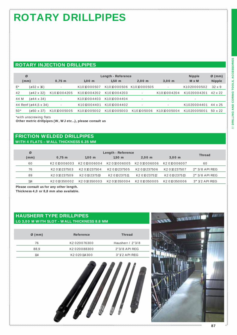
ROTARY DRILLPIPES
Ou
tils
et
access
oir
es
de f
ora
ge
ROTARY INJECTION DRILLPIPES
Ø Length - Reference Nipple Ø (mm)
(mm)
0,75 m 1,00 m 1,50 m 2,00 m 3,00 m M x M Nipple
E* (ø32 x 16) - K1 010000507 K1 010000506 K1 010000505 - K1 020000502 32 x 9
42 (ø42 x 32) K1 010004205 K1 010004202 K1 010004203 - K1 010004204 K1 020004201 42 x 22
44 M (ø44 x 34) - K1 010004403 K1 010004404 - - -
44 Renf (ø44,5 x 34) - K1 010004401 K1 010004402 - - K1 020004401 44 x 25
50* (ø50 x 37) K1 010005005 K1 010005002 K1 010005003 K1 01005006 K1 010005004 K1 020005001 50 x 22
*with unscrewing flatsOther metric drillpipes (W, WJ etc…), please consult us
HAUSHERR TYPE DRILLPIPESLG 3,00 M WITH SLOT - WALL THICKNESS 8.8 MM
Ø (mm)
Reference Thread
76 K2 020076300 Hausherr / 2”3/8
88,9 K2 020088300 2”3/8 API REG
114 K2 020114300 3”1/2 API REG
FRICTION WELDED DRILLPIPES WITH 4 FLATS – WALL THICKNESS 6.35 MM
Ø Length - Reference
(mm)
0,75 m 1,00 m 1,50 m 2,00 m 3,00 m Thread
60 K2 010006003 K2 010006004 K2 010006005 K2 010006006 K2 010006007 60
76 K2 010237503 K2 010237504 K2 010237505 K2 010237506 K2 010237507 2" 3/8 API REG
89 K2 010237509 K2 010237510 K2 010237511 K2 010237512 K2 010237513 2" 3/8 API REG
114 K2 010350002 K2 010350003 K2 010350004 K2 010350005 K2 010350006 3" 1/2 API REG
Please consult us for any other length. Thickness 4,0 or 8,8 mm also available.

88
ACCESSORIESFOR DRILLPIPES
HOISTING PLUG – FISHING BELL AND TAP
Lifting Fishing Fishing
Rods
swivel tap bell
E M5 0100001 M6 0100001 M7 0100001
42 M5 0100011 M6 0100019 M7 0100002
44 Ménard M5 0100011 M6 0100003 M7 0100002
44 Reinforced 44,5 M5 0100011 M6 0100003 M7 0100002
50 M5 0100012 M6 0100004 M7 0100003
60 M5 0100013 M6 0100205 M7 0100004
76 – 2"3/8 Reg M5 0100045 M6 0100198 M7 0100021
89 – 2"3/8 Reg M5 0100045 M6 0100200 M7 0100023
WATER SWIVEL
Bottom thread
Top adaptor 42 50 60 2"3/8 Reg
Hex 29 U0 7702002 U0 7702008 - -
Hex 41 U0 7702007 U0 7702003 U0 7702004 U0 7702001
2”3/8 Reg U0 7702010 U0 7702011 U0 7702012 U0 7702013
RODS AND CONES FOR DYNAMIC PENETROMETERAPAGEO offers a wide range of rods and cones (fixed or lost cones) for dynamic penetrometer tests, as well as hammering of windowless sampler.
Rod Driving
Ø (mm) Lg 0,5 m Lg 1,0 m Nipple
head
22 – full and treated rod - F5 02002201 - D4 1902002
32 – DPSH (without nipple) - D3 1902002 D3 1900701 D3 1902001
32 – DPSH (with nipple) - D3 1902010 - D3 1902001
42 – PDA D2 1902000 D2 1902001 - A9 0900027
Our rods are marked every 10 or 20 cm. Driving rods are also available in BW, BSW, SPT, CPT type ø36, as well as in other
lengths. Please consult us.
Lost cone
Cones Threads Fixed cone Lost cone
holder
5 cm2 Rod Ø 22 D4 19016040 - -
10 cm2 Rod Ø 22 D4 1901602 D4 1901604* D4 1901801
20 cm2 DPSH rod – Ø 32 D3 1901605 D4 1901606 D3 1902000
30 cm2 PDA rod – Ø 42 D2 1901601 D2 1901602 D2 1901604
*Also available with a tail ref D4 1901603
see p.65 Light dynamic penetrometer
see p.12-13 Heavy dynamic penetrometer (Apafor® 50 and 100)
see p.117 Semi- automatic hammering system for SPT/PDB
see p.116 Soil sampler
89
// D
RIL
LIN
G A
ND
CO
RIN
G T
OO
LS
, A
CC
ES
SO
RIE
S
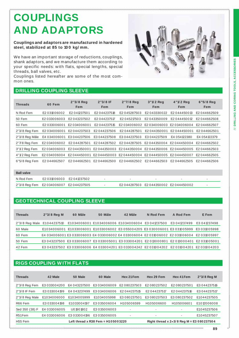
COUPLINGSAND ADAPTORS
DRILLING COUPLING SLEEVE
2’’3/8 Reg 2’’3/8 IF 2’’7/8 Reg 3”1/2 Reg 4”1/2 Reg 6”5/8 Reg
Threads
60 Fem
Fem Fem Fem Fem Fem Fem
N Rod Fem E2 031006002 E2 041237501 E2 044237518 E2 045287503 E2 043330022 E2 044450013 E2 044662509
50 Fem E2 033006003 E2 043237502 E2 044237517 E2 045217503 E2 043350009 E2 044450012 E2 044662508
60 Fem E2 033006001 E2 034006001 E2 044237515 E2 034006002 E2 034006003 E2 034006004 E2 044662507
2’’3/8 Reg Fem E2 034006001 E2 044237503 E2 044237506 E2 044287501 E2 044350001 E2 044450001 E2 044662501
2’’3/8 Reg Mâle E4 034006001 E3 044237506 E3 044237508 E3 044237503 E3 044237509 E4 054122380 E4 054122379
2’’7/8 Reg Fem E2 034006002 E2 044287501 E2 044287502 E2 044287505 E2 044350004 E2 044450004 E2 044662502
3”1/2 Reg Fem E2 034006003 E2 044350001 E2 044350003 E2 044350004 E2 044350006 E2 044450005 E2 044662503
4”1/2 Reg Fem E2 034006004 E2 044450001 E2 044450003 E2 044450004 E2 044450005 E2 044450007 E2 044662505
6’’5/8 Reg Fem E2 044662507 E2 044662501 E2 044662500 E2 044662502 E2 044662503 E2 044662505 E2 044662506
Ball valve
N Rod Fem E2 031006003 E2 041237502 - - - - -
2’’3/8 Reg Fem E2 034006007 E2 044237505 - E2 044287503 E2 044350002 E2 044450002 -
GEOTECHNICAL COUPLING SLEEVE
Threads
2"3/8 Reg M 60 Mâle 50 Mâle 42 Mâle N Rod Fem A Rod Fem E Fem
2’’3/8 Reg Male E1 044237510 E1 034006001 E1 034006006 E1 034006004 E3 041237500 E3 041237499 E3 041237498
60 Male E1 034006001 E1 033006001 E1 033006002 E3 055004205 E3 030006001 E3 031005999 E3 031005998
60 Fem E4 034006001 E3 033006003 E4 033006002 E4 033006004 E2 031006002 E2 031006004 E2 031005997
50 Fem E3 043237500 E3 033006007 E3 033005001 E3 033004201 E2 013000801 E2 013000401 E2 031005001
42 Fem E3 043237502 E3 033006006 E4 033004201 E3 033004242 E2 031004202 E2 031004201 E2 031004203
RIGS COUPLING WITH FLATS
Threads
42 Male 50 Male 60 Male Hex 21 Fem Hex 29 Fem Hex 41 Fem 2"3/8 Reg M
2’’3/8 Reg Fem E3 033004200 E4 043237500 E3 034006009 E2 080237503 E2 080237502 E2 080237501 E3 044237516
2’’3/8 IF Fem E3 033004199 E4 043237499 E3 034006006 E2 044237515 E2 044237517 E2 044237516 E3 044237517
2’’3/8 Reg Male E1 034006000 E1 034005999 E1 034005998 E3 080237501 E3 080237503 E3 080237502 E1 044237505
R66 Fem E3 033004198 E1 033004197 E3 035006004 H1 05006599 H1 05006600 H1 05006601 E1 012006008
Sed 350 (38) F E4 033006005 U01901802 E3 035006003 - - - E1 045237506
R51 Fem E4 033006006 E3 033004196 E3 035006005 - - - E1 045237507
H55 Fem Left thread x R38 Fem = H1 05003220 Right thread x 2»3/8 Reg M = E3 080237504
Couplings and adaptors are manufactured in hardened steel, stabilized at 85 to 100 kg/mm.
We have an important storage of reductions, couplings, shank adaptors, and we manufacture them according to your specific needs: with flats, special lengths, special threads, ball valves, etc.Couplings listed hereafter are some of the most com-mon ones.

90
STEEL TOOTH TRICONE BITS
TUNGSTENE CARBIDE INSERT TRICONE BITS
Diameter and thread Ground hardness / IADC code Ground hardness / IADC
Ø inch Ø mm Thread Hard / IADC 321 Medium / IADC 211 Medium / IADC 631
2’’1/2 63.50
N Rod
I1 040025001 (IADC 311)
I1 040025002I2 050025004
(IADC 633)
2’’5/8 66.67I1 040026255
(IADC 311)I1 040026251
I2 050021252 (IADC 633)
2’’7/8 73.03 - I1 040028751I2 050028751(IADC 633)
2’’15/16 74.61 I1 040029375 I1 040029371I2 050029371(IADC 633)
3’’ 76.20 I1 040030005 I1 040030001 I2 050030001
3’’1/8 79.38 I1 04003405 I1 04003401 I2 050031251
3’’1/4 82.55 I1 04003406 I1 04003402 I2 050032001
3’’3/8 85.72 I1 04003407 I1 04003403 I2 050034001
3’’1/2 88.90 I1 040035005 I1 040035001 I2 050033001
3’’3/8 85.72
2”3/8 R
I1 04003408 I1 04003405 I2 050034002
3” 1/4 82.55 - - I2 050032002
3’’1/2 88.90 I1 040035006 I1 040035002 I2 050033002
3’’5/8 92.08 I1 040036255 I1 040036251 I2 050036251
3’’3/4 95.25 I1 040037505 I1 040037501 I2 050037501
3’’7/8 98.43 I1 040038755 I1 040038752 I2 050038751
4’’ 101.60 I1 040040005 I1 040040001 I2 050041100
4’’1/8 104.78 I1 040041255 I1 040041251 I2 050041202
4’’1/4 107.95 I1 040042505 I1 040042501 I2 050042501
4’’3/8 111.13 I1 040043755 I1 040043751 I2 050043751
4’’1/2 114.30 I1 040045005 I1 040045001 I2 050045001
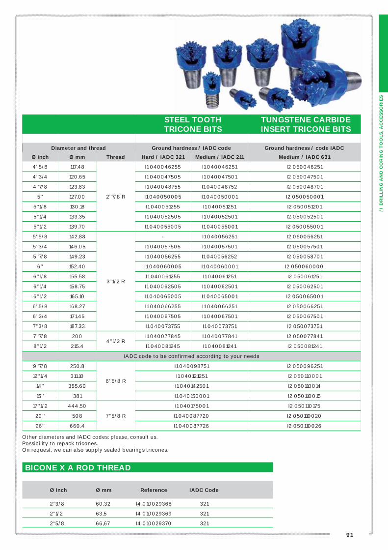
TRICONE BITSTHESE TRICONE BITS ARE MANUFACTURED BY GLINIK, EUROPEAN LEADING PRODUCER OF DRILLING TOOLS.
APAGEO’S PARTNER
Open bearingfor geotechnical drillings
Sealed bearingfor water wells drillings
Journal sealed bearingfor oil drillings
91
// D
RIL
LIN
G A
ND
CO
RIN
G T
OO
LS
, A
CC
ES
SO
RIE
S
STEEL TOOTHTRICONE BITS
TUNGSTENE CARBIDEINSERT TRICONE BITS
Diameter and thread Ground hardness / IADC code Ground hardness / code IADC
Ø inch Ø mm Thread Hard / IADC 321 Medium / IADC 211 Medium / IADC 631
4’’5/8 117.48
2’’7/8 R
I1 040046255 I1 040046251 I2 050046251
4’’3/4 120.65 I1 040047505 I1 040047501 I2 050047501
4’’7/8 123.83 I1 040048755 I1 040048752 I2 050048701
5’’ 127.00 I1 040050005 I1 040050001 I2 050050001
5’’1/8 130.18 I1 040051255 I1 040051251 I2 050051201
5’’1/4 133.35 I1 040052505 I1 040052501 I2 050052501
5’’1/2 139.70 I1 040055005 I1 040055001 I2 050055001
5’’5/8 142.88
3”1/2 R
- I1 040056251 I2 050056251
5’’3/4 146.05 I1 040057505 I1 040057501 I2 050057501
5’’7/8 149.23 I1 040056255 I1 040056252 I2 050058701
6’’ 152.40 I1 040060005 I1 040060001 I2 050060000
6’’1/8 155.58 I1 040061255 I1 040061251 I2 050061251
6’’1/4 158.75 I1 040062505 I1 040062501 I2 050062501
6’’1/2 165.10 I1 040065005 I1 040065001 I2 050065001
6’’5/8 168.27 I1 040066255 I1 040066251 I2 050066251
6’’3/4 171.45 I1 040067505 I1 040067501 I2 050067501
7’’3/8 187.33 I1 040073755 I1 040073751 I2 050073751
7’’7/8 2004’’1/2 R
I1 040077845 I1 040077841 I2 050077841
8’’1/2 215.4 I1 040081245 I1 040081241 I2 050081241
IADC code to be confirmed according to your needs
9’’7/8 250.8
6’’5/8 R
I1 040098751 I2 050096251
12’’1/4 311.10 I1 040121251 I2 050110001
14’’ 355.60 I1 040142501 I2 050110014
15’’ 381 I1 040150001 I2 050110015
17’’1/2 444.50
7’’5/8 R
I1 040175001 I2 050110175
20’’ 508 I1 040087720 I2 050110020
26’’ 660.4 I1 040087726 I2 050110026
Other diameters and IADC codes: please, consult us.Possibility to repack tricones.On request, we can also supply sealed bearings tricones.
BICONE X A ROD THREAD
Ø inch Ø mm Reference IADC Code
2“3/8 60,32 I4 010029368 321
2“1/2 63,5 I4 010029369 321
2“5/8 66,67 I4 010029370 321
92
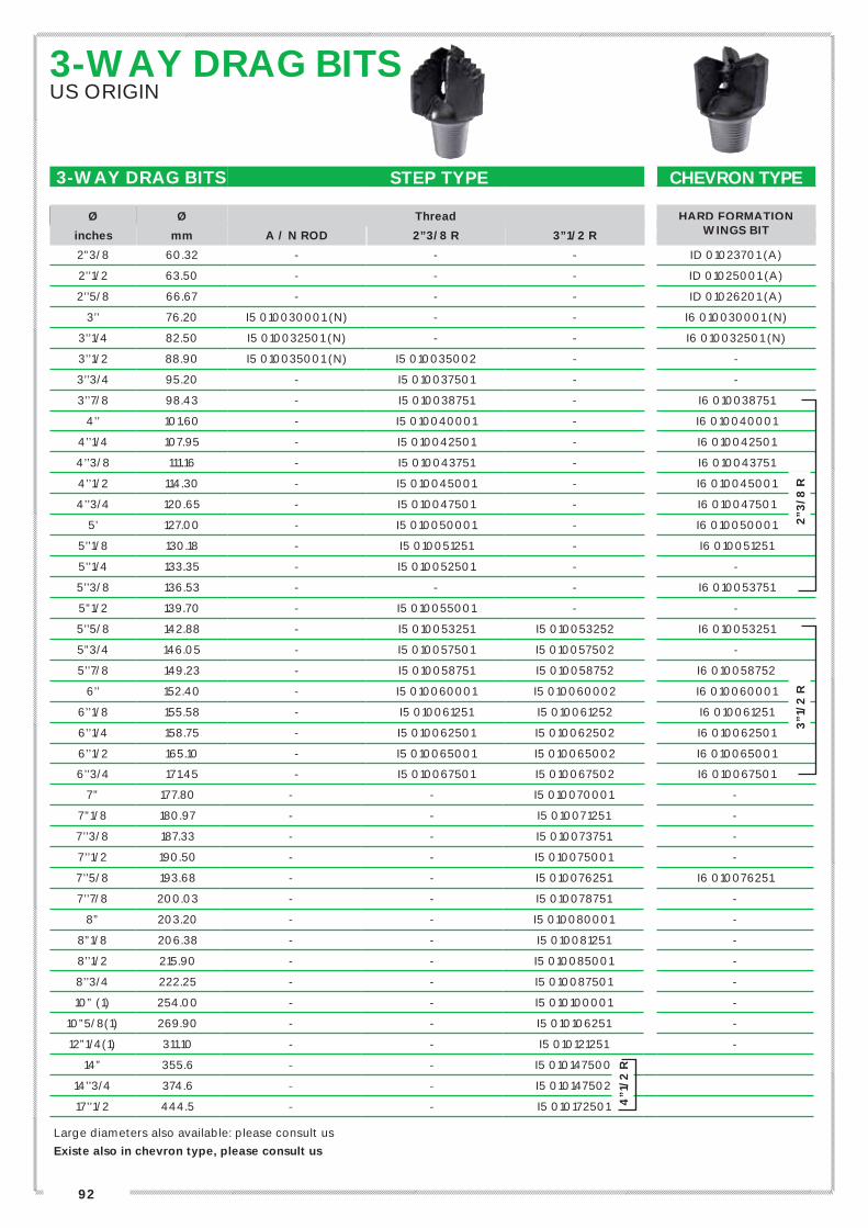
3-WAY DRAG BITSUS ORIGIN
3-WAY DRAG BITS STEP TYPE CHEVRON TYPE
Ø Ø Thread HARD FORMATION
inches mm A / N ROD 2”3/8 R 3”1/2 R WINGS BIT
2”3/8 60.32 - - - ID 01023701 (A)
2’’1/2 63.50 - - - ID 01025001 (A)
2’’5/8 66.67 - - - ID 01026201 (A)
3’’ 76.20 I5 010030001 (N) - - I6 010030001 (N)
3’’1/4 82.50 I5 010032501 (N) - - I6 010032501 (N)
3’’1/2 88.90 I5 010035001 (N) I5 010035002 - -
3’’3/4 95.20 - I5 010037501 - -
3’’7/8 98.43 - I5 010038751 - I6 010038751
4’’ 101.60 - I5 010040001 - I6 010040001
4’’1/4 107.95 - I5 010042501 - I6 010042501
4’’3/8 111.16 - I5 010043751 - I6 010043751
4’’1/2 114.30 - I5 010045001 - I6 010045001
4’’3/4 120.65 - I5 010047501 - I6 010047501
5’ 127.00 - I5 010050001 - I6 010050001
5’’1/8 130.18 - I5 010051251 - I6 010051251
5’’1/4 133.35 - I5 010052501 - -
5’’3/8 136.53 - - - I6 010053751
5”1/2 139.70 - I5 010055001 - -
5’’5/8 142.88 - I5 010053251 I5 010053252 I6 010053251
5”3/4 146.05 - I5 010057501 I5 010057502 -
5’’7/8 149.23 - I5 010058751 I5 010058752 I6 010058752
6’’ 152.40 - I5 010060001 I5 010060002 I6 010060001
6’’1/8 155.58 - I5 010061251 I5 010061252 I6 010061251
6’’1/4 158.75 - I5 010062501 I5 010062502 I6 010062501
6’’1/2 165.10 - I5 010065001 I5 010065002 I6 010065001
6’’3/4 171.45 - I5 010067501 I5 010067502 I6 010067501
7” 177.80 - - I5 010070001 -
7”1/8 180.97 - - I5 010071251 -
7’’3/8 187.33 - - I5 010073751 -
7’’1/2 190.50 - - I5 010075001 -
7’’5/8 193.68 - - I5 010076251 I6 010076251
7’’7/8 200.03 - - I5 010078751 -
8” 203.20 - - I5 010080001 -
8”1/8 206.38 - - I5 010081251 -
8’’1/2 215.90 - - I5 010085001 -
8’’3/4 222.25 - - I5 010087501 -
10” (1) 254.00 - - I5 010100001 -
10”5/8(1) 269.90 - - I5 010106251 -
12”1/4(1) 311.10 - - I5 010121251 -
14” 355.6 - - I5 010147500
14’’3/4 374.6 - - I5 010147502
17’’1/2 444.5 - - I5 010172501
Large diameters also available: please consult us
Existe also in chevron type, please consult us
2”3
/8 R
3”1
/2 R
4”1
/2 R

93
// D
RIL
LIN
G A
ND
CO
RIN
G T
OO
LS
, A
CC
ES
SO
RIE
S
TUNGSTENEAND MINING BITS
TUNGSTENE BITS, PCD BITS AND MINING TOOLSAvailable on request
PCD bit2’’1/2 ARod I7 0021200
Special tools and other diameters available on request
94
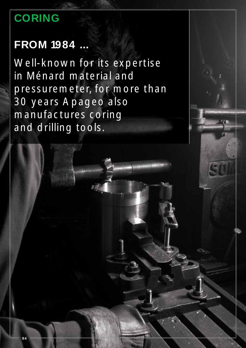
CORING
FROM 1984 ...
Well-known for its expertise in Ménard material and pressuremeter, for more than 30 years Apageo also manufactures coring and drilling tools.
95
// O
UT
ILS
ET
AC
CE
SS
OIR
ES
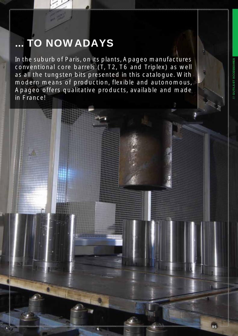
... TO NOWADAYS
In the suburb of Paris, on its plants, Apageo manufactures conventional core barrels (T, T2, T6 and Triplex) as well as all the tungsten bits presented in this catalogue. With modern means of production, flexible and autonomous, Apageo offers qualitative products, available and made in France!
96
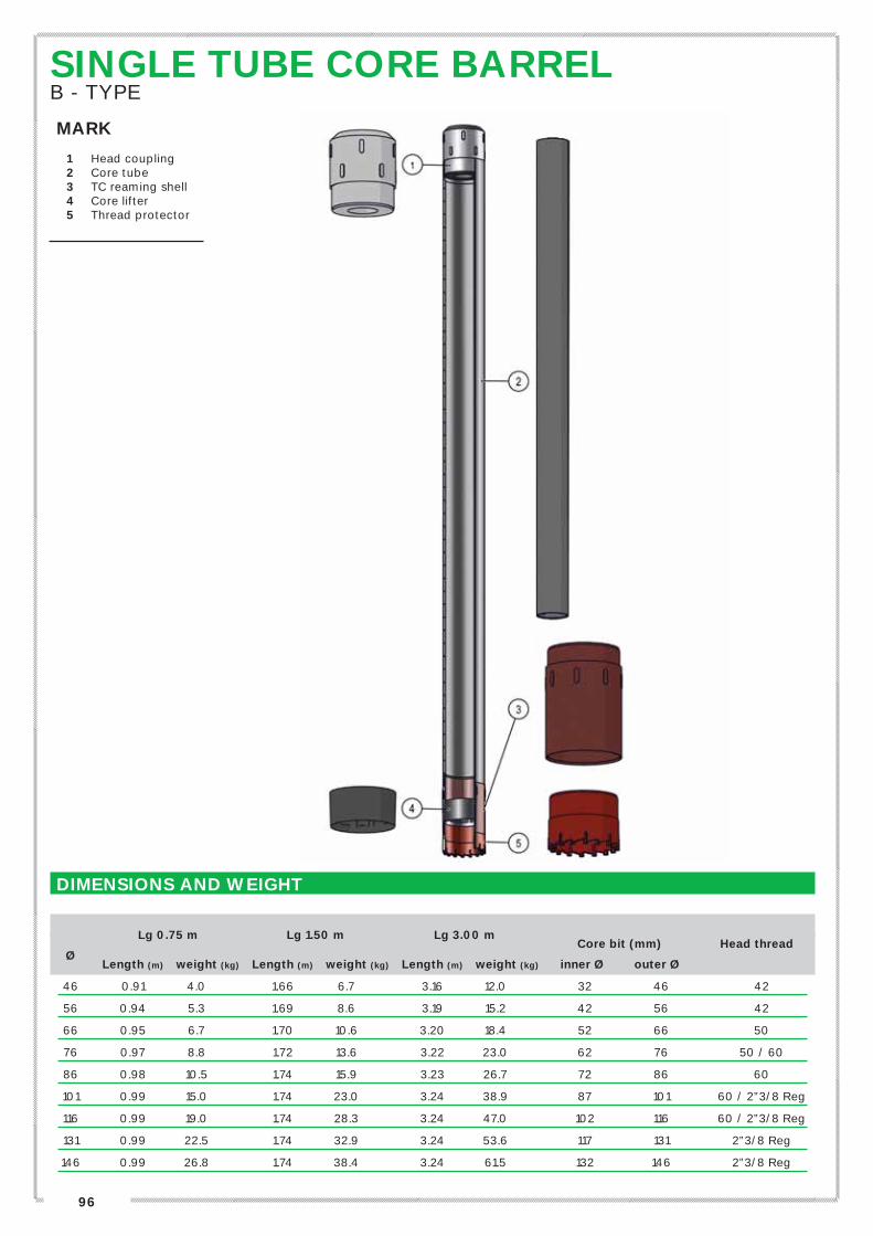
DIMENSIONS AND WEIGHT
Lg 0.75 m Lg 1.50 m Lg 3.00 m
Core bit (mm) Head thread
Ø
Length (m) weight (kg) Length (m) weight (kg) Length (m) weight (kg) inner Ø outer Ø
46 0.91 4.0 1.66 6.7 3.16 12.0 32 46 42
56 0.94 5.3 1.69 8.6 3.19 15.2 42 56 42
66 0.95 6.7 1.70 10.6 3.20 18.4 52 66 50
76 0.97 8.8 1.72 13.6 3.22 23.0 62 76 50 / 60
86 0.98 10.5 1.74 15.9 3.23 26.7 72 86 60
101 0.99 15.0 1.74 23.0 3.24 38.9 87 101 60 / 2”3/8 Reg
116 0.99 19.0 1.74 28.3 3.24 47.0 102 116 60 / 2”3/8 Reg
131 0.99 22.5 1.74 32.9 3.24 53.6 117 131 2”3/8 Reg
146 0.99 26.8 1.74 38.4 3.24 61.5 132 146 2”3/8 Reg
SINGLE TUBE CORE BARREL B - TYPE
MARK
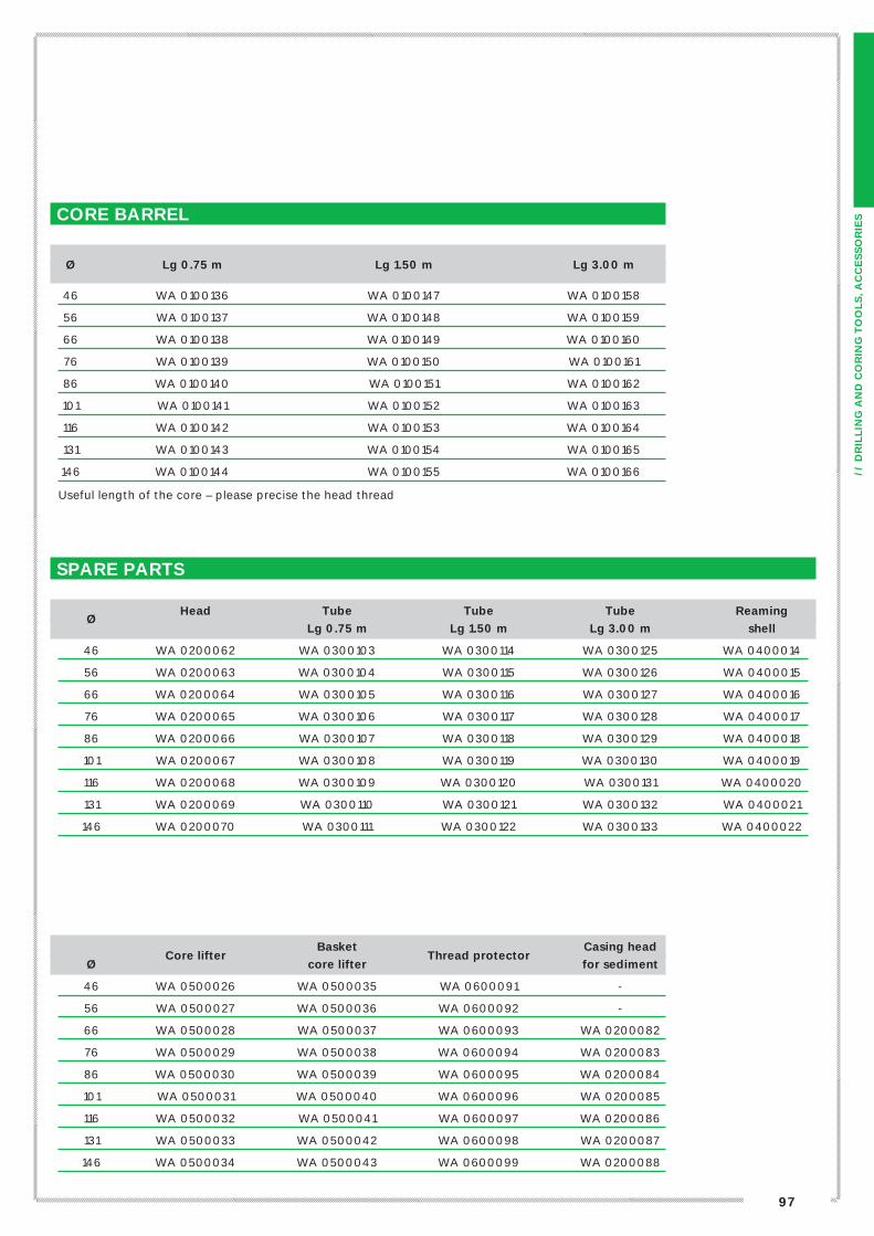
1 Head coupling2 Core tube3 TC reaming shell4 Core lifter5 Thread protector
97
// D
RIL
LIN
G A
ND
CO
RIN
G T
OO
LS
, A
CC
ES
SO
RIE
SO
uti
ls e
t access
oir
es
de f
ora
ge
Basket Casing head
Ø Core lifter
core lifter Thread protector
for sediment
46 WA 0500026 WA 0500035 WA 0600091 -
56 WA 0500027 WA 0500036 WA 0600092 -
66 WA 0500028 WA 0500037 WA 0600093 WA 0200082
76 WA 0500029 WA 0500038 WA 0600094 WA 0200083
86 WA 0500030 WA 0500039 WA 0600095 WA 0200084
101 WA 0500031 WA 0500040 WA 0600096 WA 0200085
116 WA 0500032 WA 0500041 WA 0600097 WA 0200086
131 WA 0500033 WA 0500042 WA 0600098 WA 0200087
146 WA 0500034 WA 0500043 WA 0600099 WA 0200088
SPARE PARTS
Head Tube Tube Tube Reaming
Ø
Lg 0.75 m Lg 1.50 m Lg 3.00 m shell
46 WA 0200062 WA 0300103 WA 0300114 WA 0300125 WA 0400014
56 WA 0200063 WA 0300104 WA 0300115 WA 0300126 WA 0400015
66 WA 0200064 WA 0300105 WA 0300116 WA 0300127 WA 0400016
76 WA 0200065 WA 0300106 WA 0300117 WA 0300128 WA 0400017
86 WA 0200066 WA 0300107 WA 0300118 WA 0300129 WA 0400018
101 WA 0200067 WA 0300108 WA 0300119 WA 0300130 WA 0400019
116 WA 0200068 WA 0300109 WA 0300120 WA 0300131 WA 0400020
131 WA 0200069 WA 0300110 WA 0300121 WA 0300132 WA 0400021
146 WA 0200070 WA 0300111 WA 0300122 WA 0300133 WA 0400022
CORE BARREL
Ø Lg 0.75 m Lg 1.50 m Lg 3.00 m
46 WA 0100136 WA 0100147 WA 0100158
56 WA 0100137 WA 0100148 WA 0100159
66 WA 0100138 WA 0100149 WA 0100160
76 WA 0100139 WA 0100150 WA 0100161
86 WA 0100140 WA 0100151 WA 0100162
101 WA 0100141 WA 0100152 WA 0100163
116 WA 0100142 WA 0100153 WA 0100164
131 WA 0100143 WA 0100154 WA 0100165
146 WA 0100144 WA 0100155 WA 0100166
Useful length of the core – please precise the head thread
98
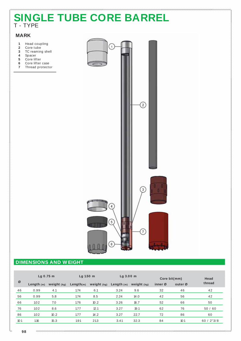
SINGLE TUBE CORE BARREL T - TYPE
MARK
1 Head coupling2 Core tube3 TC reaming shell4 Spacer5 Core lifter6 Core lifter case7 Thread protector
DIMENSIONS AND WEIGHT
Lg 0.75 m Lg 1.50 m Lg 3.00 m
Core bit(mm) Head
Ø
Length (m) weight (kg) Length(m) weight (kg) Length (m) weight (kg) inner Ø outer Ø thread
46 0.99 4.1 1.74 6.1 3.24 9.6 32 46 42
56 0.99 5.8 1.74 8.5 2.24 14.0 42 56 42
66 1.02 7.0 1.76 10.2 3.26 16.7 52 66 50
76 1.02 8.6 1.77 12.1 3.27 19.1 62 76 50 / 60
86 1.02 10.2 1.77 14.2 3.27 22.7 72 86 60
101 1.16 15.3 1.91 21.3 3.41 32.3 84 101 60 / 2”3/8
99
// D
RIL
LIN
G A
ND
CO
RIN
G T
OO
LS
, A
CC
ES
SO
RIE
S
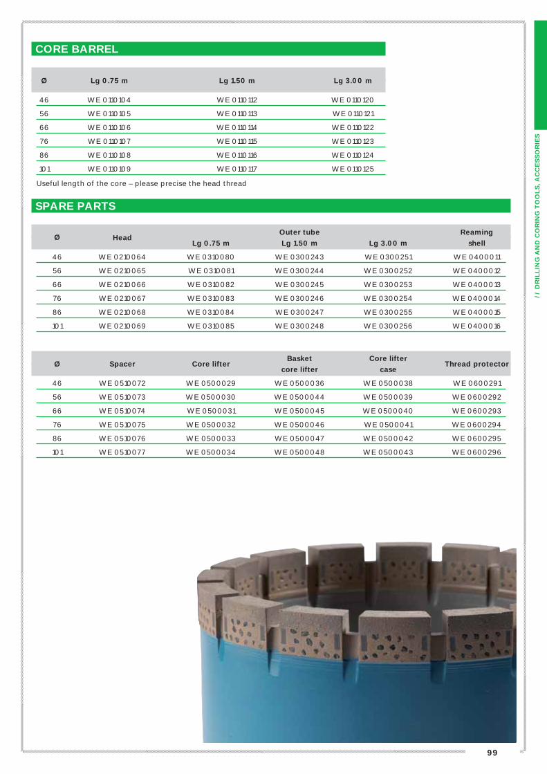
Basket Core lifter Ø Spacer Core lifter
core lifter case Thread protector
46 WE 0510072 WE 0500029 WE 0500036 WE 0500038 WE 0600291
56 WE 0510073 WE 0500030 WE 0500044 WE 0500039 WE 0600292
66 WE 0510074 WE 0500031 WE 0500045 WE 0500040 WE 0600293
76 WE 0510075 WE 0500032 WE 0500046 WE 0500041 WE 0600294
86 WE 0510076 WE 0500033 WE 0500047 WE 0500042 WE 0600295
101 WE 0510077 WE 0500034 WE 0500048 WE 0500043 WE 0600296
SPARE PARTS
Outer tube Reaming
Ø
Head
Lg 0.75 m Lg 1.50 m Lg 3.00 m shell
46 WE 0210064 WE 0310080 WE 0300243 WE 0300251 WE 0400011
56 WE 0210065 WE 0310081 WE 0300244 WE 0300252 WE 0400012
66 WE 0210066 WE 0310082 WE 0300245 WE 0300253 WE 0400013
76 WE 0210067 WE 0310083 WE 0300246 WE 0300254 WE 0400014
86 WE 0210068 WE 0310084 WE 0300247 WE 0300255 WE 0400015
101 WE 0210069 WE 0310085 WE 0300248 WE 0300256 WE 0400016
CORE BARREL
Ø Lg 0.75 m Lg 1.50 m Lg 3.00 m
46 WE 0110104 WE 0110112 WE 0110120
56 WE 0110105 WE 0110113 WE 0110121
66 WE 0110106 WE 0110114 WE 0110122
76 WE 0110107 WE 0110115 WE 0110123
86 WE 0110108 WE 0110116 WE 0110124
101 WE 0110109 WE 0110117 WE 0110125
Useful length of the core – please precise the head thread
100
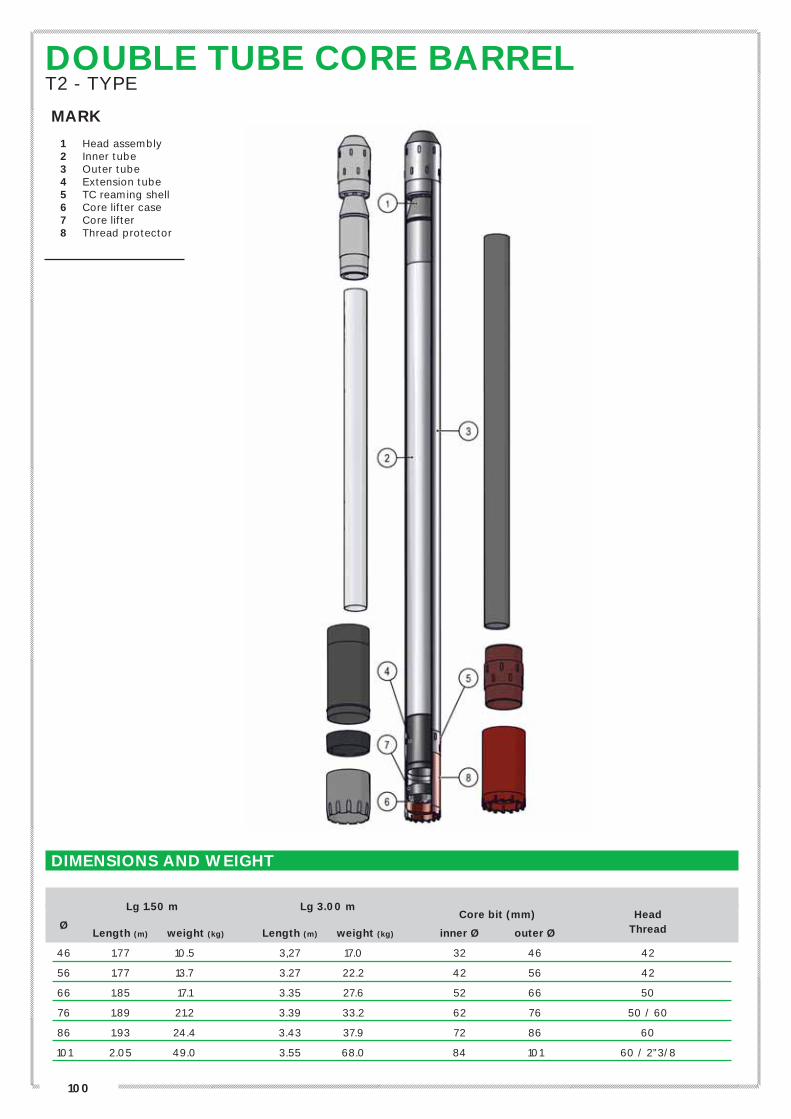
DOUBLE TUBE CORE BARREL T2 - TYPE
MARK
1 Head assembly2 Inner tube3 Outer tube4 Extension tube5 TC reaming shell6 Core lifter case7 Core lifter8 Thread protector
DIMENSIONS AND WEIGHT
Lg 1.50 m Lg 3.00 m
Core bit (mm) Head
Ø
Length (m) weight (kg) Length (m) weight (kg) inner Ø outer Ø Thread
46 1.77 10.5 3,27 17.0 32 46 42
56 1.77 13.7 3.27 22.2 42 56 42
66 1.85 17.1 3.35 27.6 52 66 50
76 1.89 21.2 3.39 33.2 62 76 50 / 60
86 1.93 24.4 3.43 37.9 72 86 60
101 2.05 49.0 3.55 68.0 84 101 60 / 2”3/8
101
// D
RIL
LIN
G A
ND
CO
RIN
G T
OO
LS
, A
CC
ES
SO
RIE
SO
uti
ls e
t access
oir
es
de f
ora
ge
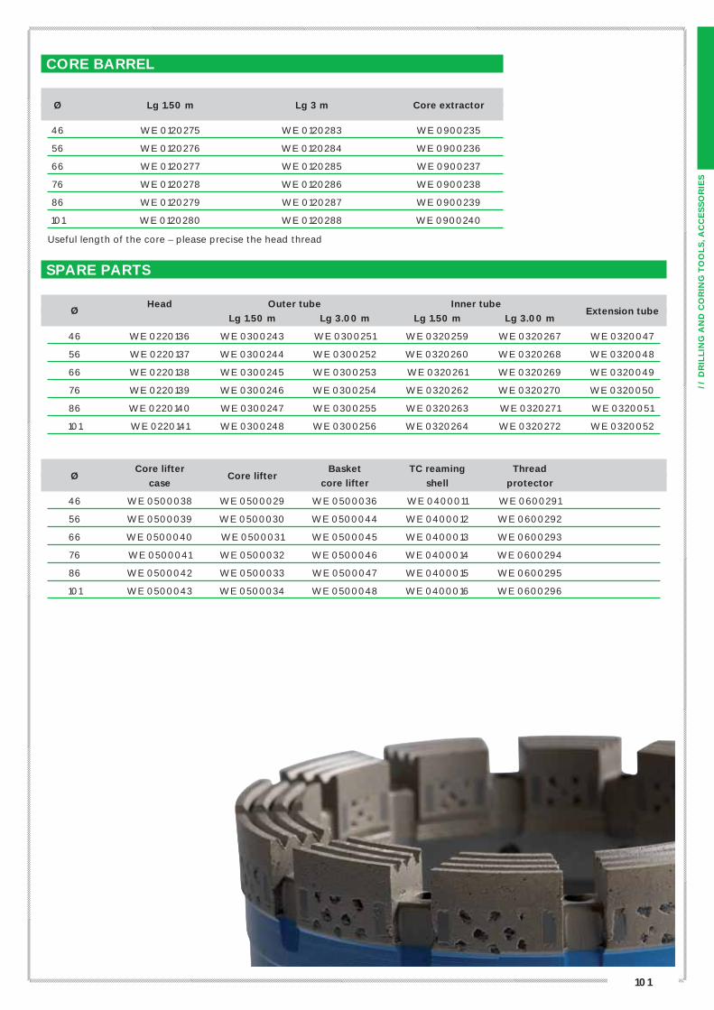
Core lifter Basket TC reaming Thread Ø
case Core lifter
core lifter shell protector
46 WE 0500038 WE 0500029 WE 0500036 WE 0400011 WE 0600291
56 WE 0500039 WE 0500030 WE 0500044 WE 0400012 WE 0600292
66 WE 0500040 WE 0500031 WE 0500045 WE 0400013 WE 0600293
76 WE 0500041 WE 0500032 WE 0500046 WE 0400014 WE 0600294
86 WE 0500042 WE 0500033 WE 0500047 WE 0400015 WE 0600295
101 WE 0500043 WE 0500034 WE 0500048 WE 0400016 WE 0600296
SPARE PARTS
Head Outer tube Inner tube
Ø
Lg 1.50 m Lg 3.00 m Lg 1.50 m Lg 3.00 m Extension tube
46 WE 0220136 WE 0300243 WE 0300251 WE 0320259 WE 0320267 WE 0320047
56 WE 0220137 WE 0300244 WE 0300252 WE 0320260 WE 0320268 WE 0320048
66 WE 0220138 WE 0300245 WE 0300253 WE 0320261 WE 0320269 WE 0320049
76 WE 0220139 WE 0300246 WE 0300254 WE 0320262 WE 0320270 WE 0320050
86 WE 0220140 WE 0300247 WE 0300255 WE 0320263 WE 0320271 WE 0320051
101 WE 0220141 WE 0300248 WE 0300256 WE 0320264 WE 0320272 WE 0320052
CORE BARREL
Ø Lg 1.50 m Lg 3 m Core extractor
46 WE 0120275 WE 0120283 WE 0900235
56 WE 0120276 WE 0120284 WE 0900236
66 WE 0120277 WE 0120285 WE 0900237
76 WE 0120278 WE 0120286 WE 0900238
86 WE 0120279 WE 0120287 WE 0900239
101 WE 0120280 WE 0120288 WE 0900240
Useful length of the core – please precise the head thread

102
DOUBLE TUBE CORE BARRELT6 - TYPE
MARK
1 Head assembly 2 Outer tube3 Inner tube4 Extension tube5 TC reaming shell6 Core lifter7 Core lifter case8 Thread protector
DIMENSIONS AND WEIGHT
Lg 1.50 m Lg 3.00 m
Core bit (mm) Head
Ø
Length (m) weight (kg) Length (m) weight (kg) inner Ø outer Ø thread
76 2,03 28.0 3,53 47.0 57 76 50 / 60
86 2,04 33.0 3,54 53.0 67 86 60
101 2,14 46.0 3,64 69.0 79 101 60 / 2”3/8
116 2,09 60.0 3,59 85.0 94 116 60 / 2”3/8
131 2,09 70.0 3,59 105.0 108 131 2”3/8 Reg
146 2,09 93.0 3,59 128.0 123 146 2”3/8 Reg

103
// D
RIL
LIN
G A
ND
CO
RIN
G T
OO
LS
, A
CC
ES
SO
RIE
SO
uti
ls e
t access
oir
es
de f
ora
ge
CORE BARREL
Ø Lg 1.50 m Lg 3.00 m
76 WF 0100125 WF 0100133
86 WF 0100126 WF 0100134
101 WF 0100127 WF 0100135
116 WF 0100128 WF 0100136
131 WF 0100129 WF 0100137
146 WF 0100130 WF 0100138
Useful length of the core – please precise the head thread
TC reaming Core lifter Basket Thread Ø
shell
case Core lifter
core lifter protector
76 WF 0400011 WF 0500036 WF 0500020 WF 0500042 WF 0600052
86 WF 0400012 WF 0500037 WF 0500021 WF 0500043 WF 0600053
101 WF 0400013 WF 0500038 WF 0500022 WF 0500044 WF 0600054
116 WF 0400014 WF 0500039 WF 0500023 WF 0500045 WF 0600055
131 WF 0400015 WF 0500040 WF 0500024 WF 0500046 WF 0600056
146 WF 0400016 WF 0500041 WF 0500025 WF 0500047 WF 0600057
SPARE PARTS
Head Outer tube Inner tube
Ø
Lg 1.50 m Lg 3.00 m Lg 1.50 m Lg 3.00 m Extension tube
76 WF 0200068 WF 0300093 WF 0300101 WF 0300109 WF 0300117 WITHOUT
86 WF 0200069 WF 0300094 WF 0300102 WF 0300110 WF 0300118 WITHOUT
101 WF 0200070 WF 0300095 WF 0300103 WF 0300111 WF 0300119 WITHOUT
116 WF 0200071 WF 0300096 WF 0300104 WF 0300112 WF 0300120 WF 0300088
131 WF 0200072 WF 0300097 WF 0300105 WF 0300113 WF 0300121 WF 0300089
146 WF 0200073 WF 0300098 WF 0300106 WF 0300114 WF 0300122 WF 0300090
104
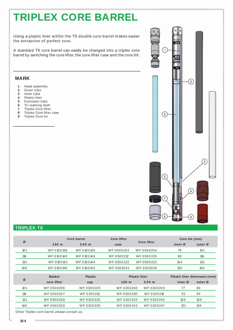
TRIPLEX CORE BARREL
Using a plastic liner within the T6 double core barrel makes easier the extraction of perfect core.
A standard T6 core barrel can easily be changed into a triplex core barrel by switching the core lifter, the core lifter case and the core bit.
MARK
1 Head assembly2 Outer tube3 Inner tube4 Plastic liner5 Extension tube6 TC reaming shell7 Triplex Core lifter8 Triplex Core lifter case9 Triplex Core bit
TRIPLEX T6
Core barrel Core lifter Core bit (mm)
Ø
1.50 m 3.00 m case Core lifter
inner Ø outer Ø
101 WF 0100139 WF 0100145 WF 0500202 WF 0500204 76 101
116 WF 0100140 WF 0100143 WF 0500212 WF 0500225 90 116
131 WF 0100141 WF 0100144 WF 0500222 WF 0500223 104 131
146 WF 0100146 WF 0100142 WF 0503041 WF 0503025 120 146
Basket Plastic Plastic liner Plastic liner dimension (mm) Ø
core lifter cap 1.50 m 3.00 m inner Ø outer Ø
101 WF 0500206 WF 0300205 WF 0300240 WF 0300203 77 80
116 WF 0500207 WF 0300215 WF 0300230 WF 0300216 91 94
131 WF 0500208 WF 0300225 WF 0300242 WF 0300246 106 109
146 WF 0500209 WF 0300235 WF 0300243 WF 0300247 121 124
Other Triplex core barrel, please consult us.

105
// D
RIL
LIN
G A
ND
CO
RIN
G T
OO
LS
, A
CC
ES
SO
RIE
S
OTHER CORE BARRELDOUBLE TUBE CORE BARREL - T6S TYPE
Ø Lg 1.50 m
Core bit (mm) Reference
Length(m) weight (kg) inner Ø outer Ø
76 2.11 28.0 48 76 WG 0100010
86 2.12 33.0 58 86 WG 0100011
101 2.22 46.0 72 101 WG 0100012
116 2.20 60.0 86 116 WG 0100013
131 2.20 70.0 101 131 WG 0100014
146 2.20 93.0 116 146 WG 0100015
Please, contact us for spare parts.
DOUBLE TUBE CORE BARREL – K2 TYPE
Ø Lg 1.50 m Lg 3.00 m
Core bit (mm) Reference
Length (m) weight (kg) Length (m) weight (kg) inner Ø outer Ø 1.50 m 3.00 m
76 2.16 32.0 3.66 49.0 48 76 WC 0100261 WC 0100270
86 2.16 40.0 3.66 60.0 58 86 WC 0100262 WC 0100271
96 2.14 50.0 3.64 75.0 67 96 WC 0100263 WC 0100272
101 2.15 55.0 3.65 82.0 72 101 WC 0100264 WC 0100273
116 2.18 69.0 3.68 104.0 86 116 WC 0100265 WC 0100274
131 2.13 87.0 3.63 126.0 98 131 WC 0100266 WC 0100275
146 2.21 104.0 3.71 148.0 115 146 WC 0100267 WC 0100276
Please, contact us for spare parts.
106
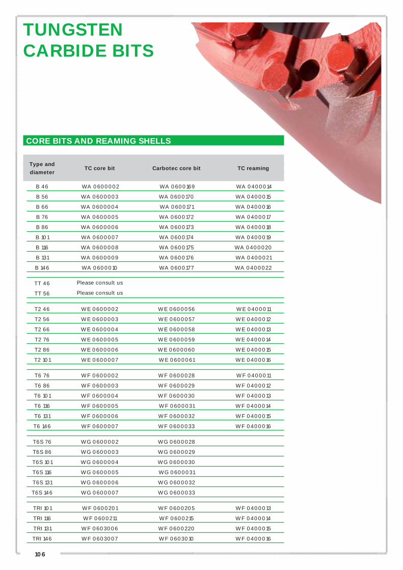
TUNGSTEN CARBIDE BITS
CORE BITS AND REAMING SHELLS
Type and
TC core bit Carbotec core bit TC reaming
diameter
B 46 WA 0600002 WA 0600169 WA 0400014
B 56 WA 0600003 WA 0600170 WA 0400015
B 66 WA 0600004 WA 0600171 WA 0400016
B 76 WA 0600005 WA 0600172 WA 0400017
B 86 WA 0600006 WA 0600173 WA 0400018
B 101 WA 0600007 WA 0600174 WA 0400019
B 116 WA 0600008 WA 0600175 WA 0400020
B 131 WA 0600009 WA 0600176 WA 0400021
B 146 WA 0600010 WA 0600177 WA 0400022
TT 46 Please consult us
TT 56 Please consult us
T2 46 WE 0600002 WE 0600056 WE 0400011
T2 56 WE 0600003 WE 0600057 WE 0400012
T2 66 WE 0600004 WE 0600058 WE 0400013
T2 76 WE 0600005 WE 0600059 WE 0400014
T2 86 WE 0600006 WE 0600060 WE 0400015
T2 101 WE 0600007 WE 0600061 WE 0400016
T6 76 WF 0600002 WF 0600028 WF 0400011
T6 86 WF 0600003 WF 0600029 WF 0400012
T6 101 WF 0600004 WF 0600030 WF 0400013
T6 116 WF 0600005 WF 0600031 WF 0400014
T6 131 WF 0600006 WF 0600032 WF 0400015
T6 146 WF 0600007 WF 0600033 WF 0400016
T6S 76 WG 0600002 WG 0600028
T6S 86 WG 0600003 WG 0600029
T6S 101 WG 0600004 WG 0600030
T6S 116 WG 0600005 WG 0600031
T6S 131 WG 0600006 WG 0600032
T6S 146 WG 0600007 WG 0600033
TRI 101 WF 0600201 WF 0600205 WF 0400013
TRI 116 WF 0600211 WF 0600215 WF 0400014
TRI 131 WF 0603006 WF 0600220 WF 0400015
TRI 146 WF 0603007 WF 0603010 WF 0400016

107
// D
RIL
LIN
G A
ND
CO
RIN
G T
OO
LS
, A
CC
ES
SO
RIE
S
CORE BITS AND REAMING SHELLS
Type and
TC core bit Carbotec core bit TC reaming
diameter
K2 76 WC 0600002 - WC 0400022
K2 86 WC 0600003 - WF 0400023
K2 96 WC 0600004 - WF 0400024
K2 101 WC 0600005 - WF 0400025
K2 116 WC 0600006 - WF 0400026
K2 131 WC 0600007 - WF 0400027
K2 146 WC 0600008 - WF 0400028
Reference without bottom discharge
AQ WK 0600015 WK 0600001 WK 0400067
BQ WK 0600016 WK 0600002 WK 0400068
NQ WK 0600017 WK 0600003 WK 0400069
HQ WK 0600018 WK 0600004 WK 0400070
PQ WK 0600019 WK 0600005 WK 0400071
SK6L 146 - WK 0600141 -
Other kinds of TC bits are available on demand, please consult us. (BS, DCDMA, BE, etc…)
See casing shoes and casings see p.120


110
DIAMOND CORE BITSEUROPEAN MANUFACTURER
APAGEO HAS PARTNERED WITH URDIAMANT TO OFFER A FULL RANGE OF DIAMOND TOOLS.Urdiamant’s products are the result of more than 80 years of expertise and manufactured from the highest-quality raw materials using leading-edge technology and equipment to make fast-penetration core bits with an exceptionally long lifespan.
Our diamond tools are appropriate for all operating conditions regardless of abrasion level or rock type. Maintaining ongoing stock in our warehouse, we are able to respond immediately to your requirements in most cases. Specialised core bits (special shape, specific diamond impregnation, customised, etc.) are also available on request. We are also equipped to manufacture diamond tools on special order according to your plans.
IMPREGNATED DIAMOND CORE BITS(IMPREGNATION DEPTH 8 MM)These core bits are designed for demanding drilling conditions and all formation types from soft to hard, abrasive to silicified (see matrix classification). The range currently on offer covers all core bit standards (B series, T2, T6, T6S, Triplex, K2, Q series) for all matrices indicated.
REAMING SHELLSAPAGEO offers highly robust diamond reaming shells manufactured using high-quality, natural diamonds embedded in highly resistant matrices. The diamond components are cast in the matrix thereby constituting an integral part of the shell. This maximises performance whilst also preserving diameter through any type of soil.
IMPREGNATED AND SURFACE-SET SHOESWe offer a full range of diamond shoes according to the metric, LS, DCDMA (‘W’ series), etc., standards. Highly robust and with reinforced inside and outside diameters, they offer outstanding value for their investment. Shoes are available either impregnated (flat or VV profile) or surface-set.
TECHNICAL SUPPORTWith their extensive knowledge, our core drilling experts can advise you on proper use of your core bits and even visit your site to assist with testing.
DIAMOND CORE BITS RANGE
APAGEO’S PARTNER

111
// D
RIL
LIN
G A
ND
CO
RIN
G T
OO
LS
, A
CC
ES
SO
RIE
S
DIAMOND CORE BITSDIAMOND CORE BITS SELECTIONACCORDING TO THE CHARACTERISTICSOF THE ROCKS
This chart has been created to help you to select the best tool for your worksite.The diamond tools range GeoDIAM will cover all your needs in every king of hard formations.Please consult us if you need more information
SOME DIFFERENT HEIGHTS OF IMPREGNATION ARE AVAILABLE ON REQUEST

112
DIAMOND CORE BITS
1. CHOICE OF ROTATION SPEEDS DEPENDING ON• penetration rate;• core bit diameter;• drilling depth;• vibration.
In estimating the appropriate rotation speed it is recommended to follow the concept of peri-pheral rotation speed: the smaller the core bit diameter, the weaker its circumference, requi-ring a higher rotation speed in order to main-tain adequate peripheral velocity.For reference, the required peripheral velocity is typically 2 to 5 m/s for impregnated core bits and 1 to 3 m/s for surface-set core bits.
Figure 1 illustrates target ranges for rotation speed based on tool diameter..
2. CHOICE OF WATER FLOW RATEFlow rate should generally be as high as possible but also depends on the core bit diameter and rock type.
For example, soft or fractured rock requires a higher flow rate. On the other hand, very hard, resistant rock associated with a low pe-netration rate calls for a lower flow rate to promote rock cutting and reduce polishing risk for the diamonds
Figure 2 depicts suggested water flow rates for various core bit diameters.
3. BIT PRESSUREDuring drilling, the force applied by the ma-chine and the weight of the rods must also be as weak as possible whilst maintaining a sufficient penetration rate to prevent poli-shing of the diamonds.
The consequences of excessive pressure in-clude: • wearing of mechanical components in the
machine, rods and corer; • premature wearing of the core bit; • increased likelihood of deflection.
Fig 1. Rotation speed / Core bit diameter
Bit diameter(mm)
Impregneted diamond
Surface setdiamond
Carbotec
Tungstencarbide insert
Ro
tati
on
sp
ee
d (
rpm
)
Fig 2. Flow rate / Core bit diameter
FLO
W (
L/m
in)
Recommandedflow
Core bitdiameter(mm)
Fig 3. Bit pressure / Core bit diameter
Core bit diameter(mm)
Pressure
Bit
pre
ssu
re (
kg
)
CORE BIT OPERATING PARAMETERS

113
// D
RIL
LIN
G A
ND
CO
RIN
G T
OO
LS
, A
CC
ES
SO
RIE
S
DIAMOND CORE BITSANALYSIS OF WEAR
LOSS OF INSIDE DIAMETERWear of inside diameter and ringing.Caused by: Drilling pressure toohigh, very broken ground, core left inthe hole, water flow too low, matrixtoo soft.
CRACKS IN THE WATER WAYSCaused by: Too much weight on thebit, Dropped the rods, bit crushed bythe foot clamp or rod holder.Solution: Take some weight off thebit.
OUTSIDE WEAR PATTERNCaused by: water flow too low, lossof water by the rods, hole “reamed”Solution: increase the water flow,check for leaks, check the diameterof shell.
INSIDE WEAR PATTERN Caused by: drilling pressure toohigh for rotation speed, Core left inthe hole had to be drilled, verybroken ground.Solution: decrease drilling pressure,increase rotation speed, check thecore barrel, add drilling fluids.
CONSUMED BITImpregnated bit consumed perfectly.
IDEAL WEAREven wear, complete up tp the carbidewith the diamonds evenly worn.
NEW IMPREGNATED BIT
LOSS OF OUTSIDE DIAMETERCause: vibration, rotation speed toohigh, water flow too low, fragmentedrock present in the borehole.Solution: increase water flow, reducerotation speed, check the diameter ofreaming shell, add drilling fluid (toreduce vibration)
BURNT CORE BITBit is completely melted and destroyed.Caused by: Lack of waterSolution: Increase the water flow,check the pump is working well, checkthe rods for leaks in the joints, checkthe inner tube is not too long.
CORE BIT POLISHED OR GLAZEDThe bit doesn’t cut anymore, diamondsare polished.Caused by: Drilling pressure too lowfor the speed of rotation, water flowtoo high, matrix too hard.Solution: Sharpen the bit, reduce therotation speed and increase drillingpressure, reduce water flow, select asofter matrix.
DIAMOND OVER EXPOSEDThe matrix wears too fast before thediamonds have worn out.The diamonds pop-out prematurelythus reducing the life of the bit.Caused by: Drilling pressure toohigh for speed of rotation, water flowtoo low, matrix too soft.

114
DIAMOND CORE BITS
DIAMOND CORE BIT AND REAMING SHELL
Impregnated Surface set
Type an
core bits core bits Impregnated
diameter
GeoDIAM 2 (GeoDIAM 25/40) reaming shells
B 46 RL 0046452 - RL 0046900
B 56 RL 0056452 - RL 0056900
B 66 RL 0066452 - RL 0066900
B 76 RL 0076452 - RL 0076900
B 86 RL 0086452 - RL 0086900
B 101 RL 0101452 RL 0101830 RL 0101900
B 116 RL 0116452 RL 0116800 RL 0116900
B 131 RL 0131452 - RL 0131900
B 146 RL 0146452 - RL 0146900
TT 46 WE 1600101 - RU 0046900
TT 56 RU 0056210 - RU 0056900
T2 46 RI 0046452 - RI 0 46900
T2 56 RI 0056452 RI 0056811 RI 0056900
T2 66 RI 0066452 RI 0066811 RI 0066900
T2 76 RI 0076452 RI 0076816 RI 0076900
T2 86 RI 0086452 RI 0086821 RI 0086900
T2 101 RI 0101452 RE 0101221 RI 0101900
T6 76 RJ 0076452 RJ 0076821 RJ 0076900
T6 86 RJ 0086452 RJ 0086821 RJ 0086900
T6 101 RJ 0101452 RJ 0101826 RJ 0101900
T6 116 RJ 0116452 RJ 0116831 RJ 0116900
T6 131 RJ 0131452 RJ 0131836 RJ 0131900
T6 146 RJ 0146452 RJ 0146836 RJ 0146900
T6S 86 RV 0086452 RV 0086836 -
T6S 101 RV 0101452 RV 0101830 -
T6S 116 RV 0116452 RV 0116836 -
T6S 131 RV 0131452 - -
T6S 146 RV 0146452 - -
TRI 101 RA 0101452 RA 0101830 RJ 0101900
TRI 116 RA 0116452 RA 0116830 RJ 0116900
TRI 131 RA 0131452 RA 0131830 RJ 0131900
TRI 146 RA 0146452 RA 0146830 RJ 0146900

115
// D
RIL
LIN
G A
ND
CO
RIN
G T
OO
LS
, A
CC
ES
SO
RIE
SDIAMOND CORE BIT AND REAMING SHELL
Impregnated
Type and
core bits Impregnated
diameter
GeoDIAM 2 reaming shells
K2 96 RW 0096452 RW 0096900
K2 101 RW 0101452 RW 0101900
K2 116 RW 0116452 RW 0116900
K2 131 RW 0131452 RW 0131900
K2 146 RW 0146452 RW 0146900
AQ RT 0005452 RT 0001900
BQ RT 0004452 RT 0002900
NQ RT 0001452 RT 0003900
HQ RT 0002452 RT 0004900
PQ RT 0003452 RT 0005900
Diamond casing shoes for each type of casing are available.
Please consult us for any other kind of diamond core bits (BS, DCDMA, BE, etc…)
It is also possible to order PDC core bit, please contact us.
DIAMOND CORE BITS

116
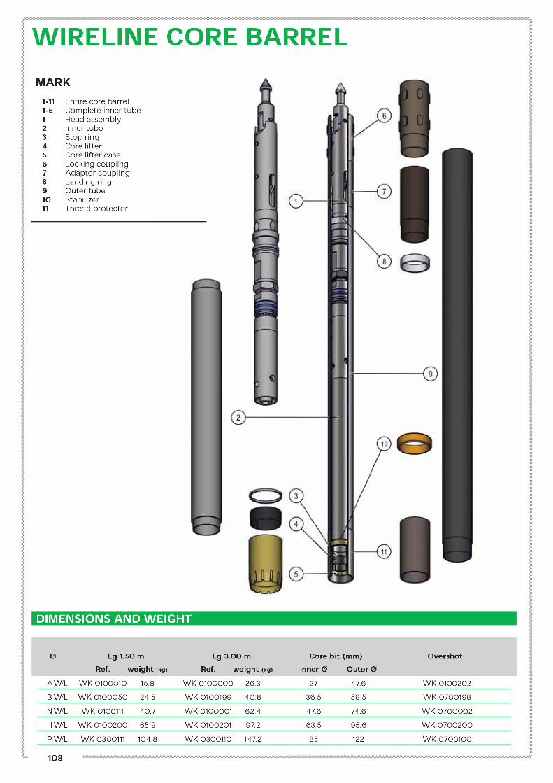
CORE BARREL REFERENCE – RIGHT THREAD
Core barrel Type
Lg 0.5 m Lg 0.75 m Lg 1 m Basket Casing Head
42 x 56 WN 0100013 - - - WN 0600006 WN 0200001 without basket
42 x 56 WN 0100017 - - WN 0600009 WN 0600007 WN 0200001 with basket
56 x 76 WN 0100115 WN 0100116 WN 0100117 WN 0600110 WN 0600109 WN 0200101
76 x 91 WN 0101014 WN 0101015 WN 0101016 WN 0601011 WN 0601009 WN 0201001
83 x 105 WN 0100215 WN 0100216 WN 0100217 WN 0600210 WN 0600209 WN 0200201
92 x 111 WN 0102115 WN 0102116 WN 0102117 WN 0602109 WN 0602108 WN 0202101
102 x 127 WN 0102011 WN 0102012 WN 0102013 WN 0600211 WN 0602008 WN 0202001
APM 86 WAPM 086050 WAPM 086075 WAPM 086100 WN 0601011 WAPM 086400 WAPM 086200
APM 101 WAPM 101050 WAPM 101075 WAPM 101100 WAPM 101600 WAPM 101400 WAPM 101200
For left thread core barrel and other lengths and diameters, please consult us.
Ø LINER - TUBE - CASING
Type Liner Tube Casing
and diameter
Dim. (mm) Dim. (mm) Dim. (mm)
42 x 56 45 x 42 55,6 x 46 56 x 42
56 x 76 63 x 57 74 x 67 74,5 x 55
76 x 91 80 x 77 86 x 81 88,8 x 75,3
Transparent
Long casing: 84,2 x 75,3
83 x 105 90 x 86,4 99 x 92,5 102 x 85
92 x 111 100 x 94 110 x 101,6 111 x 92
96 x 114 100 x 97,4 102 x 114 96 x 116
102 x 127 110 x 103,6 125 x 113 127 x 102
APM 86 80 x 77 86 x 81 86 x 75,3
APM 101 92 x 94 100 x 95 100 x 92
Transparent
Diameters in mm: Ø outer x Ø inner
2
3
4
6
7
5
1
HAMMERING SAMPLERHAMMERED TUBE, STANDARD OR THIN WALL THICKNESS
MARK
1 Head2 Ball3 Ball place4 Plastic liner5 Tube6 Basket7 Casing
Please, indicate the type of rods used

117
// D
RIL
LIN
G A
ND
CO
RIN
G T
OO
LS
, A
CC
ES
SO
RIE
S
PRINCIPLE
The hammering system of the SPT (Standard Penetration Test) consists of a weight of 64kg and a pick up and self tripping mechanism that ensure a falling height of 75 cm. The energy is given by the anvil to the rods, and then to the SPT core barrel.
IMPLEMENTATION
• The inner guide rod (5) enables the weight (4) to drop with minimal resistance and to strike the anvil (6) squarely. It is fixed to the anvil.
• The outer tube (2) is left by the capstan’s string thanks to the hook (1), until the lifting pawls (3) are opened (at the height of 75 cm), thus releasing the weight.
• The weight can be fixed to the guide rod thanks to the safety bolt (7), especially during transportation or while not testing.
• The total length of the hammer is 1.6 m unextended and 2.35 m extended. The total weight of the complete hammer is 105kg.
SPT HAMMERING SYSTEM
MARK1 Lifting hook2 Outer tube3 Lifting pawls with springs4 Drive weight5 Inner guide rod6 Anvil7 Safety bolt8 PDB rod9 SPT hammering system and accessories
SPECIAL RODS AND CONNECTION THREADS
Description Reference
Hammering system A9 09000028
SPT Rod ø54 mm x 1,5 m - M x F (English standard) A9 09000027
SPT Rod 1,0 m – with nipple A9 09000012
SPT Core barrel ø54mm (english standard) A9 09000029
SPT Core barrel NF (ø51mm) – Ball head – Right thread A9 0100014
SPT Core barrel ball head - Right thread A9 0200017
SPT Split tube - Right thread A9 0300020
SPT Basket A9 0900018
SPT Cone ø54mm on rod or core barrel A9 0900022
SPT Basket core lifter A9 0900020
1
2
7
9
6
3
48
5

118
WINDOW SAMPLERLENGTH 1 METER*
PERCUSSION CORING IS MAINLY USED WHEN A SOFT SOIL DRILLING IS NEEDED
The window samplers are needed to get undisturbed samples, without need of any lubricants, thereby allowing chemical analysis on sample.
Manufactured in our own plant, our window sampler are very robust ( tough ?). Extension rods can be connected to the sampler depending on the depth sampling.
OUR EQUIPMENT CAN BE ADAPTED TO ANY HAMMERING SYSTEM
Depending on type of soil, depth and size of core wanted, we offer different range of diameters
Filetage /
Ø extérieur 7/8 (E) 42 CR 50 CR 60 CR 2’’3 / 8R R32 R38
Ø 32mm
Ø 42mm
Ø 50mm
Ø 60mm
Ø 63mm
Ø 85mm
Other threads, Other length possible on request
119
// D
RIL
LIN
G A
ND
CO
RIN
G T
OO
LS
, A
CC
ES
SO
RIE
S
CASING TUBES D.C.D.M.A“W” SERIE - MALE X FEMALE
TUBES AND CASING SHOES REFERENCES
Length and weight (kg) TC casing Carbotec Impregnated Tube
0.5 m 1.5 m 3.0 m shoe casing shoe casing shoe
AW V2 0300320 V2 0300321 V2 0300322 V2 0800193 V2 0800228 V2 0800175
BW V2 0300325 V2 0300326 V2 0300327 V2 0800194 V2 0800229 V2 0800176
NW V2 0300330 V2 0300331 V2 0300332 V2 0800195 V2 0800230 V2 0800177
HW V2 0300335 V2 0300336 V2 0300337 V2 0800196 V2 0800231 V2 0800178
PW V2 0300340 V2 0300341 V2 0300342 V2 0800197 V2 0800232 V2 0800174
SW V2 0300345 V2 0300346 V2 0300347 V2 0800198 V2 0800233 V2 0800173
UW V2 0300350 V2 0300351 V2 0300352 V2 0800199 V2 0800234 V2 0800172
ZW V2 0300355 V2 0300356 V2 0300357 V2 0800200 V2 0800235 V2 0800171
ACCESSORIES REFERENCES
Driving Casing Fishing Hoisting Tube
(head right)* clamp tool plug
AW V2 0200260 V2 0300361 M6 0100004 M5 0100035
BW V2 0200261 V2 0300362 M6 0100006 M5 0100036
NW V2 0200262 V2 0300364 M6 0100007 M5 0100037
HW V2 0200263 V2 0300365 M6 0100009 M5 0100038
PW V2 0200264 V2 0300366 M6 0100010 M5 0100039
SW V2 0200265 V2 0300367 M6 0100042 M5 0100040
UW V2 0200266 V2 0300368 M6 0100043 M5 0100046
ZW V2 0200267 V2 0300369 M6 0100044 M5 0100047
*Please indicate the thread required
TubeDimensions (mm) Length and weight (kg)
inner Ø outer Ø 0.5 m 1.5 m 3.0 m
AW 48.4 57.1 3.40 8.60 17.20
BW 60.3 73.0 5.30 15.80 31.80
NW 76.2 88.9 6.50 19.50 39.00
HW 101.6 114.3 8.50 25.40 51.30
PW 127.0 139.7 11.00 30.00 58.00
SW 152.4 168.2 18.00 48.00 93.00
UW 177.8 193.6 25.00 67.00 130.00
ZW 203.2 219.0 30.00 80.00 154.00
WEIGHTS AND DIMENSIONS OF TUBES
Other length, please contact us.

120
CASING TUBESMETRIC SERIE – MALE X FEMALE
WEIGHTS AND DIMENSIONS OF TUBES
ACCESSORIES REFERENCES
Tube Ø Driving head* Casing clamp Fishing tool Hoisting plug
46 V5 0210045 V5 0300241 M6 0100003 M5 0100021
56 V5 0210046 V5 0300242 M6 0100004 M5 0100022
66 V5 0210047 V5 0300243 M6 0100005 M5 0100023
76 V5 0210048 V5 0300244 M6 0100006 M5 0100024
86 V5 0210049 V5 0300245 M6 0100007 M5 0100025
101 V5 0210050 V5 0300246 M6 0100008 M5 0100026
116 V5 0210051 V5 0300247 M6 0100009 M5 0100027
131 V5 0210052 V5 0300248 M6 0100010 M5 0100028
146 V5 0210053 V5 0300249 M6 0100011 M5 0100029
*Please indicate the threads required, left and right thread available
TUBES AND CASING SHOES REFERENCES
Length and weight (kg) TC casing Carbotec Impregnated Tube
0.5 m 1.0 m 1.5 m 3.0 m shoe casing shoe casing shoe
46 V5 0310067 V5 0310068 V5 0310069 V5 0310071 V5 0810012 V5 0810001 V5 0810265
56 V5 0310073 V5 0310074 V5 0310075 V5 0310077 V5 0810013 V5 0810002 V5 0810266
66 V5 0310079 V5 0310080 V5 0310081 V5 0310083 V5 0810014 V5 0810003 V5 0810267
76 V5 0310085 V5 0310086 V5 0310087 V5 0310089 V5 0810015 V5 0810004 V5 0810268
86 V5 0310091 V5 0310092 V5 0310093 V5 0310095 V5 0810016 V5 0810005 V5 0810269
101 V5 0310097 V5 0310098 V5 0310099 V5 0310101 V5 0810017 V5 0810006 V5 0810270
116 V5 0310103 V5 0310104 V5 0310105 V5 0310107 V5 0810018 V5 0810007 V5 0810271
131 V5 0310109 V5 0310110 V5 0310111 V5 0310113 V5 0810019 V5 0810008 V5 0810272
146 V5 0310115 V5 0310116 V5 0310117 V5 0310119 V5 0810020 V5 0810009 V5 0810273
Other lengths, please consult us
TubeDimensions
inner Ø outer Ø
Length and weight (kg)
0.5 m 1.0 m 1.5 m 3.0 m
46 37 44 1.94 3.70 5.46 10.74
56 47 54 2.40 4.60 6.79 13.36
66 57 64 2.88 5.53 8.12 15.98
76 67 74 3.36 6.41 9.47 18.63
86 77 84 3.83 7.32 10.80 21.25
101 89 98 5.70 10.88 16.00 31.62
116 104 113 6.95 13.28 19.60 38.53
131 119 128 7.92 15.12 22.32 43.92
146 134 143 8.88 16.95 25.00 49.25
121
// D
RIL
LIN
G A
ND
CO
RIN
G T
OO
LS
, A
CC
ES
SO
RIE
S
CASING TUBES LS SERIE – FEMALE X FEMALESLEEVE MALE X MALE
TUBES AND CASING SHOES REFERENCES
Length and weight (kg) Tube
0.5 m 1.0 m 1.5 m 3.0 m Sleeve
95 V6 0300025 V6 0300033 V6 0300041 V6 0300057 V6 0400001
114 V6 0300026 V6 0300034 V6 0300042 V6 0300058 V6 0400002
140 V6 0300027 V6 0300035 V6 0300043 V6 0300059 V6 0400003
168 V6 0300028 V6 0300036 V6 0300044 V6 0300060 V6 0400004
194 V6 0300029 V6 0300037 V6 0300045 V6 0300061 V6 0400005
220 V6 0300030 V6 0300038 V6 0300046 V6 0300062 V6 0400006
ACCESSORIES REFERENCES
T C casing Carbotec Impregnated Clasing Driving Tube
shoe casing shoe casing shoe clamp head*
95 V6 0800017 V6 0800065 V6 0800073 V2 0300370 V6 0200009
114 V6 0800018 V6 0800066 V6 0800074 V2 0300365 V6 0200010
140 V6 0800019 V6 0800067 V6 0800075 V2 0300366 V6 0200011
168 V6 0800020 V6 0800068 V6 0800076 V2 0300367 V6 0200012
194 V6 0800021 V6 0800069 V6 0800077 V2 0300368 V6 0200013
220 V6 0800022 V6 0800070 V6 0800078 V2 0300369 V6 0200014
*Please indicate the thread required
WEIGHTS AND DIMENSIONS OF CASINGS AND SLEEVES
Tube
Dimensions (kg) Length and weight (kg)
Inner Ø Outer Ø 0.5 m 1.0 m 1.5 m 3.0 mSleeve
Inner Ø
95 81.0 95.0 5.80 13.50 22.20 44.30 77.0
114 101.6 114.3 6.40 14.80 23.00 48.40 98.0
140 125.7 139.7 8.80 20.50 32.10 67.10 120.5
168 153.6 168.3 10.70 24.90 39.00 81.50 149.0
194 178.4 193.7 13.30 30.80 48.30 100.80 174.4
220 203.6 219.1 16.10 37.30 58.60 122.30 200.0
Other lengths, please contact us


