49
1 Safety Operating & Service Instructions Tracked Tree Stump Grinders Last updated Feb 2007 PW Serial no. ENGLISH

1
SafetyOperating & Service
Instructions
Tracked Tree Stump GrindersLast updated Feb 2007 PW
Serial no.
ENGLISH

2

3
INDEX PAGE
CE DECLARATION OF CONFORMITY 4
INTRODUCTION 5
PURPOSE OF MACHINE 5
SPECIFICATIONS 7
SERIAL NUMBERS 7
NOTICES 8
SAFETY INFORMATION 9
PERSONAL SAFETY 10
SAFE OPERATION 11
TRANSPORTATION 14
OPERATION 15
RADIO CONTROL (Option) 20
MAINTENANCE 22
SERVICE SCHEDULE 23
SERVICE AND MAINTENANCE 24
MAINTENANCE OF YOUR MULTI-TIP SYSTEM 28
MAINTENANCE OF TRACKED UNDERCARRIAGE 30
PARTS LISTS 34
DECALS 41
WIRING DIAGRAMS 42
HYDRAULIC CIRCUIT 44
WARRANTY VALIDATION FORM 47
WARRANTY STATEMENT. 49

4
CE DECLARATION OF CONFORMITY
This is to confirm that the machine entitled PREDATOR 26conforms with the essential health and safety requirements.
Description of machinery:Self powered intended to grind away tree stumps & surface roots.
Model: AP/26SG06 Serial No.
Relevant directives complied with by the machine:
The Machinery Directive 89/37/EC
Harmonised Standards:BS EN 292-1: Safety of Machinery.
Basic Concepts, General Principles for Design:Basic Terminology, Methodology.
BS EN 292-2: Safety of Machinery. Basic Concepts, General Principles for Design:Technical Principles & Specification.
Business name and address of ‘responsible persons’:Arborplant The Log House, Kiln Lane, Binfield Heath, Oxon RG9 4EN.
Authorised persons empowered to sign:P Watts (MD)
Positions in company:Director, Production Manager & Office Manager
Signature: Date:

5
INTRODUCTION.
Congratulations for purchasing your Predator tree stump grinder. If you have any questions regarding the operation or service of the machine, please contact your supplying dealer.
PURPOSE OF MACHINE.
The Predator tree stump grinder is designed to grind away tree stumps of any diameter from above ground level to below ground level.
By the nature of its function the cutter on this machine has been designed to tolerate a certain amount of contact with soil, vegetation and other natural material that may be found around the base of a tree. It is not however designed specifically to cut through soil or materials other than timber. To ensure the maximum life of the cutters and to keep the cutters sharp, contact with soil, rock, flint brick and other hard materials around the base of the tree stump should be kept to an absolute minimum.
Our tree stump grinders are designed to give safe and dependable service if operated according to the instructions.
This manual contains important health and safety information and explains the machine controls.Read and understand this manual before operating the tree stump grinder. Take the time to familiarise yourself with the machine controls before attempting to operate it and slowly build up to operating the machine at its full capability. Failure to do so could result in personal injury, death, equipment damage, damage to property, or injury to a member of the general public.
Ensure that all operators are adequately trained for operating this machine especially with safeworking practices.
This manual covers the operation and general maintenance of the machine. All information in this manual is based on the latest product information available at time of publication.
NOTE -Also supplied with this manual is an engine manual, registration card, COSHH for the battery.
All the information you need to operate the machine safely and effectively is contained within this manual and the engine manual.
Predator’s policy of constantly improving their products may involve major or minor changes to the machine and therefore reserve the right to make changes at any time without notice andwithout incurring any obligation. This policy may result in minor discrepancies between the actual tree stump grinder and the text in this manual.
NOTETHIS MANUAL SHOULD BE CONSIDERED A PERMANENT PART OF THE MACHINE AND SHOULD REMAIN WITH THE MACHINE IF RESOLD.

6
RUNNING IN and other important notes and recommendations for the machine.
To achieve long life from your new machine it is important to run it in properly.
During the first few hours of use there is a bedding in period of components. Check all fittings and hose hose connections regularly.
ClutchThe Predator 26 has an electro-magnetic clutch that should be ‘burnished’ and ideally ‘run-in’. If this isn’t undertaken properly it will incur excessive heat in the first few hours of use and con-sequently premature failure.
It is standard that electro magnetic clutches need burnishing in and this is achieved by causing it to slip momentarily several times for short periods without generating too much heat. With new machines this is undertaken in the factory. For details see replacement of clutch on page 27.
To ensure maximum clutch life a short running-in period is recommended when the Predator 26 is first used.
Grind as normal for approximately 5 minutes, then disengage the cutter wheel and leave for at least 5 minute to cool. Repeat up to 5 times.
BeltsThe belts from the engine to the clutch are the week link in the drive train. They are designed to slip momentarily if the cutter wheel suddenly jams. The engine should stall a second or two lat-er. New belts will stretch within the first few hours so they will require some tightening or they will slip too much. Excessive slipping will wear the belts and the pulleys out prematurely.
EngineThe engine can be run in at full RPM. The first service should be at 25 - 50 hours.
Duty CycleThe Predator 26 is designed for duty cycles of no more than two hours between breaks. Ex-tended periods could cause excessive heat to the hydraulic system and clutch. Breaks are re-quired to allow the machine to cool down. The length of the break depends on the ambient temperature. Do not allow hydraulic oil temperature to increase above 65ºC ( 150ºF )
The guards and decals are an essential part of the machine. They must always be in place and in good condition. Replacements are available from your local dealer or from Predator.
The use of genuine parts is very important. Copy parts might be of the same basic specification but lack certain important criteria.

7
A
B
D
SPECIFICATIONS.
ENGINE - Lombardini 9LD 28hp / 21Kw, air cooled, 2 cylinder, electric start, diesel.
ENGINE OIL - Refer to Engine Manual
ENGINE FUEL - Ordinary diesel fuel should be used with this engine. DO NOT mix any additives. Read the engine manual for full details.
FUEL TANK CAPACITY 20 Litres
HYDRAULIC TANK CAPACITY approx. 40 litres. Specification = type AF45
CUTTER WHEEL RPM 1900
LENGTH 2350mm
WIDTH (D) 670mm
WIDTH (B) 1000mm
HEIGHT (A) 1300mm
WEIGHT gross 1000 Kg
CUTTING DEPTH 380mm
CUTTING HEIGHT 800mm
SLEW 1140mm
CUTTERS on cutting wheel 6
TIPS per cutter 4
CUTTER WHEEL DIA. 480mm.
SERIAL NUMBERS.
Serial numbers relating to the Predator tree stump grinder can be found on the main chassis on top of the machine.
Serial numbers relating to the engine can be found on the side of the engine.Under no circumstances should any of these numbers be removed or defaced in any way.
These numbers should be quoted in any correspondence with your supplying dealer.

8
DANGER
WARNING
CAUTION
IMPORTANT
NOTE
NOTICES.
Whenever you see the symbols shown below, heed their instructions! Always follow safe operating and maintenance practices.
DANGER.This danger symbol indicates potential danger situations that can quite probably cause severe injury or death if the danger is not avoided and can also cause serious damage to machinery.
WARNING.This warning symbol identifies special instructions or procedures which, if not correctly followed, could result in severe personnel injury.
CAUTION.This caution symbol identifies special instructions or procedures which, if not strictly observed, could result in damage to, or destruction of, equipment.
IMPORTANT.This message is used in situations where failure to take due measures can shorten the working life of the machine.
NOTE.This note symbol indicates points of particular interest for more efficient and convenient operation.
PUTTING INTO SERVICE.
All Predator machines have a full pre-delivery inspection before leaving the factory and are ready to use. The teeth might show signs of use. This is part of pre delivery tests. Read and understand the instruction manual and become familiar with the stump grinder controls before attempting to operate the machine. Ensure that all operators are adequately trained for operating this machine especially with safe working practices.

9
SAFETY INFORMATION.
FUEL.
Diesel fuel can be injurious to the skin - wash off as soon as possible. If taken internally seek immediate medical attention. Refer to your local fuel supplier for MSDS leaflet.
Store diesel only in approved containers, in well ventilated, unoccupied buildings away from naked flames. Do not fill the fuel tank while the engine is running.
EXHAUST FUMES.
Engine exhaust gases contain poisonous carbon monoxide. Carbon monoxide is odourless, colourless and can cause death if inhaled.Avoid inhaling exhaust fumes and never run the engine in a closed building or confined area.
HOT PARTS.
Engine components can get extremely hot from operation. To prevent severe burns, do not touch these areas while the engine is running - or immediately after it is turned off.Never operate the engine with heat shields or guards removed.
ELECTRICAL SHOCKS.
Never touch electrical wires or components while the engine is running - they can be sources of electrical shock.
ROTATING CUTTER.
When the engine is turned off the cutter wheel could continue to rotate for a short while.The teeth are sharp and could cause damage or injury even whilst not in motion.
BATTERIES.
Batteries contain Acid which is corrosive and poisonous. Handle battery with care - if splashed there is a risk of burns and / or serious damage to eyes. Wash affected area immediately with lots of clean water and seek medical advice. Read the battery MSDS sheets as supplied.
EXPLOSIVE GASES.
Explosive gases given off from battery, keep sparks and flames away.
DANGER
DANGER
DANGER
DANGER
DANGER
DANGER
DANGER

10
PERSONAL SAFETY.
The following personal protective equipment (P.P.E.) must be worn by the person operating this machine and also all personnel within a 20 metre radius of the machine.
Forestry safety helmet to EN 397 fitted with steel mesh visor to EN 166 and full ear protection to EN 352-3.
Heavy duty gloves to EN 388.
Close fitting heavy duty non snag clothing and steel toe protection boots to EN 345.
Dust mask if the ground is very dry.
NOISE.
Noise levels of 114 dB(A) have been recorded at the working position.
VIBRATION
As required by the supply of Machinery (Safety) Regulations 1992, this unit has been designed to reduce the risk from vibration (and noise) to the lowest level.
The nature /variation of working conditions makes definite rms acceleration values incalculable, but it is understood that the acceleration level over an 8 hour day (A(8)) is lless than 2.5m/sec ²
In order to reduce the effects of vibration, the following points ought to be adhered to:
Keep hands warm.Exercise hands and fingers regularly during work.Minimise the grip strength on the controlsBreak up the working periods, if possibleMaintain the equipment – as instructed
WARNING
WARNING

11
SAFE OPERATION.
MANOEUVRING ON SOFT GROUND.
Avoid driving on very soft or unstable ground. The machine could sink, slide, slew or turn over.
INCLINED SURFACES.
Manoeuvring on inclined surfaces is dangerous. Expand the track base and reduce the manoeuvring speed in order to avoid the risk of tipping the machine over and skidding.
As far as possible avoid turning on inclined surfaces. When you have to turn on slopes, try to do it on solid, non slippery sections.
Avoid traversing along steep slopes, since there's always the danger of overturning the machine.
This machine is rated to climb slopes of up to 20°. Operating on slopes is undertaken at users risk.
Before trying to go up a slope, make sure that the engine and the hydraulic system has reached normal operating temperature. This will help prevent stalling.
CLOTHING.
DO NOT wear rings, bracelets, watches, jewellery or any other items that could be caught in the machine controls. Always wear full protective clothing.
SMOKING.
DO NOT smoke when refueling.
CHILDREN.
DO NOT allow children or anyone who has not received instruction to operate the machine.
CLIMBING.
DO NOT climb on the machine at any time.
SAFETY OF THE GENERAL PUBLIC.
The Stump Grinder Cutter can eject debris at high speed - always maintain a 20 metre exclusion zone for the general public. USE SUFFICIENT SCREENING TO PROTECT AGAINST FLYING DEBRIS
WARNING
WARNING
WARNING
WARNING
WARNING
WARNING

12
SAFE AREA.
Maintain the 20 metre exclusion zone as a safe working area around yourself and the stump grinder. Keep this area clear from debris build up. Mark the area out with hazard tape. Keep the area clear of animals as well as people.
KEEP CLEAR.
All operatives must keep well away from the cutter when the engine is running.
STARTING.
Always start the engine in the open air and allow to warm before operating. Never operate the starter key for more than fifteen seconds at one time.
EMERGENCY STOPPING.
Push the RED STOP button and turn the ignition key to the off position.
SAFE USE.
Prior to starting cutter ensure the front control panel is rotated and securely located into its position for cutter control. Ensure cutter guards are fitted, secure and intact.
With the engine switched off visually inspect the cutter wheel and ensure that there is no obvious damage to the cutting teeth, that all teeth retaining bolts are tight and that there is no debris trapped in the cutting teeth. Under no circumstances must the engine be running or the ignition key be in the ignition switch whilst you carry out this inspection.
ALWAYS ENSURE THAT THE CUTTER ARM IS IN THE UP POSITION AND CLEAR OF ANY OBSTACLES BEFORE TRYING TO DRIVE THE MACHINE OR BEFORE SELECTING THE CUTTER.
HAZARDOUS BRASH.
Some species of trees and bushes are poisonous and can irritate the skin or give respiratory problems. DO NOT work in confined areas and if in doubt wear a respiratory mask in addition to the P.P.E already described. Seek professional advice if you are unsure what you are dealing with.
DUST
If the ground is very dry, a large amount of airborne dust might occur. In this situation a respiratory mask should be worn.
P.P.E.
There can be some reduction in vision and hearing and it gets hot when wearing personal protective equipment for long periods - take regular breaks.
WARNING
DANGER
WARNING
WARNING
WARNING
CAUTION
WARNING

13
STOPPING.
Always stop the engine and remove the ignition key before making any adjustments, refueling, or cleaning.
SAFE CUTTER.
Remove ignition key to avoid accidental starting. Ensure cutter wheel has stopped rotating before undertaking any maintenance or adjustments to the machine.
SPEED.
When being driven, the stump grinder can move and turn with surprising speed.
Be aware of the size, shape and weight of the stump grinder when operating the track control levers. This is particularly important to bear in mind if you are driving the unit in a public area.
Always operate the track controls carefully and gently.
Be aware that the stump grinder is a powerful machine and moves with considerable force.
LIGHTING
Operate only in daylight or with sufficient lighting
CAUTION
WARNING
WARNING
WARNING

14
TRANSPORTING THE MACHINE.
The stump grinder can be transported to site either on a trailer or on a low bed truck.
MOVING MOUNTED ON A TRAILER.
When manoeuvring by hand always use the jockey wheel. Do not attempt to support the weight of the draw bar yourself.
If moving the trailer and stump grinder off of the vehicle draw-bar, ensure the hand brake is on and (if fitted) the rear jack stand is in the down position and the trailer wheels are chocked prior to attempting to move the stump grinder from the trailer.If working on a gradient always ensure trailer wheels are adequately chocked. Failure to do so may result in the over centre brakes de-activating and allowing the trailer to roll. Turn the trailer to an appropriate position and chock both wheels.Do not move the trailer with the stump grinder engine running.
LOADING THE MACHINE.
Always perform the machine loading and unloading operation with the low bed truck parked on a solid and level surface.
Remember to use a purpose designed ramp or a loading platform for loading and unloading the stump grinder. The ramp must be strong enough to support the weight of the machine. Make sure the slope of the ramp is less than 20°.
Before loading the machine be sure to thoroughly clean the ramp and the bed. Ramps or beds that are dirty with oil, mud or ice are slippery and dangerous.
SLOPES - under 20º
Avoid steering when going up or down the ramps since this can be extremely dangerous. If it is absolutely necessary to steer, first drive the machine back down to the ground and off the ramps or back onto the vehicle / trailer bed and then change the direction of travel and start back up or down the ramp again.
Never operate any control levers except for the drive control levers when going up or down a ramp. Actuating other levers can cause the machine to become unbalanced and tip over.The machine will pivot on its tracks with a see-saw type action as it is driven over the point where the ramp meets the trailer / vehicle bed. Be careful when going over this point. Drive slowly on ramps.
Always ascend and desend steep slopes with cutter wheel up hill.
It is not reccomended to work on slopes more than 20º
STRAPS & CHAINS
Fasten retention chains, straps or cables to the machine chassis. Do not put chains, straps or cables over or against hydraulic hoses. Make sure that chains , straps or cables do not cause damage to rubber tracks.Fasten each corner of the machine and fasten the front arm to the trailer / vehicle bed with a chain / strap or a suitable anchor.
WARNING
WARNING
WARNING
WARNING

15
OPERATION INSTRUCTIONS.
BEFORE STARTING ENGINE.
Ensure that you have read and understood this manual.
Check engine oil level. Top up if necessary.
Check diesel.
Check hydraulic oil level.
Visually check around the machine for fuel, oil, & hydraulic oil leaks.
Ensure the engine cover, cutter guard chains and rear access cover are in place and tightened securely.
Inspect the cutter wheel to ensure no foreign objects or dangerous matter are trapped in the cutters and that the cutter retention bolts are tight and that the cutters are in generally good condition.
Ensure that the cutter wheel bolts are fitted and tight.
Ensure that cutter wheel is not touching or is obstructed by anything and that there are no operators, personnel, members of the public or animals in close proximity to the machine.
Observe the condition of the terrain / surface under the machine and on which you (the operator) are standing and make sure that you are confident that you are going to be able to maintain full control of the machine on this terrain / surface.
STARTING THE ENGINE.
Ensure red emergency stop button is out. Twist cutter mode button to start mode. Turn ignition key one position clockwise. Wait till lights stop flashing. This is the preheat mode and will vary depending on ambient temperatures.
Then turn further to engage starter motor. Once the engine starts, let go of the key to allow it to spring back into its normal running position. See Engine Manual for further information.
CAUTION

16
USE OF RUBBER TRACKS
Avoid manoeuvring on hard, stony and uneven surfaces such as rock, gravel, etc.Avoid keeping the rubber tracks in direct sunlight for more than 3 months.Avoid excessive steering manoeuvres on asphalt and concrete surfaces since these cause excess pad wear. Avoid driving on asphalt surfaces when their temperature exceeds 60°C since this causes both excess pad wear and damage to the asphalt surface.Manoeuvres with a loose track on an irregular surface can cause the pad to detach and /or damage to the rubber track.
Rubber tracks are designed only for use on soft terrain, not for hard and abrasive surfaces such as sand, stone, minerals, etc. Use of rubber tracks on these surfaces can cause premature wear and deformation hence reducing the useful life of the tracks.
Avoid contact between sharp concrete edges etc. and the rubber track.
Fuels or synthetic oils must never come in contact with the rubber track. If this does happen then they must immediately be cleaned.
Avoid using rubber tracks in marine and seaside environments since saline air or salt in general corrode adhesion between rubber and metal inner core.
OPERATING INSTRUCTIONS. (If radio control, refer to next section for controls operation)
Do not use or attempt to start the stump grinder without the cutter guards, engine covers and access covers securely in place. Failure to do so may result in personal injury or loss of life.
Start the stump grinder following the correct starting procedure. Check that the engine is running smoothly. If it is not stop and investigate. Once the engine is warm and you are ready to start driving. Pull the cutter lift lever backwards to ensure that the cutter arm is at its highest position.
Use the track control levers at the rear of the machine to drive the stump grinder in the desired direction. Pushing both track levers forwards at the same time drives the stump grinder forwards. Pulling both track levers backwards at the same time drives the stump grinder backwards.Pushing the right track lever only turns the machine to the left. Pulling the right track lever only turns the machine to the right.Pushing the left track lever only turns the machine to the right. Pulling the left track lever only turns the machine to the left.
With practice a combination of these lever movements can be used to gain accurate proportional driving and steering control.
Position the stump grinder directly in front of the stump with the cutter directly over the front edge of the stump.
Before starting the stump grinding operation check the area around the base of the tree stump is clear of any foreign objects such as cloth, string, plastic, glass, rubber, stones, bricks, metal, or any other materials that could be picked up and ejected by the cutter.
CAUTION
DANGER

17
Use the tracks expand lever to fully expand the width of the tracks to their outermost position. Pushing the lever forwards will expand the track base.
TRACK WIDENING
Take care when widening or narrowing the tracks. Obstacles e.g. stumps, walls etc, could cause unnecessary wear to the rubber tracks and its mechanism and could also cause a track to come off. Also take care that no people or obstacles may be caught between the tracks and the machine or between the tracks and other obstacles.
Make sure the control panel is fully open and locked in position so the control panel cannot move.
Use the cutter lift / lower lever to lower the cutter down until it is just below the level of the top edge of the tree stump ready for the first cut. ensure that the cutter wheel is to the side of, and clear of, the stump.
Pulling the lever backwards will raise the cutter.Pushing the lever forwards will lower the cutter.
The possible depth of cut will vary based on the type of tree stump and its condition. Iie. hardwood or softwood, wet or dry, fresh cut or old and decayed. It is recommended that the first cut is considered a test cut and as such the depth of this cut should be kept to a minimum, i.e less than 25mm (less than 1”). Based on the performance of the first cut the depth of the next cut can be increased or reduced. Maximum depth of cut is 65mm. (2.5”) See Figure 1 on page 16 for the start position.
CAUTION
1 2 3 4 5 6 7 8 9 10 11 12 13 14
1. Control panel latch2. Safety key holder3. Safety key strap4. Left track lever5. Right track lever6. Lift lower lever7. Variable width lever8. Slew lever9. Control panel10. Fuel filler cap11. Ignition key12. Cutter engage switch13. Emergency stop switch14. Throttle lever
Use the cutter slew lever to slew the cutter to the left or the right so that it is clear of, and to the side of, the stump. Pushing the lever forwards will slew the cutter to the left.Pulling the lever backwards will slew the cutter to the right.

18
Make sure the control panel is locked in place. All guards and screens fitted to the machine must be in place and intact. Further guards might be required to protect third party property.
Position yourself near the machine at the main control panel and atatch the safety strap as shown making sure the key is plugged into the holder. Safety helmet, visor and ear defenders must be worn along with steel toe cap boots, heavy full length trousers and gloves. When the cord is pulled out accidentally or deliberately the cutter wheel will stop.Use guards to protect property, vehicles and people from flying debris.Turn the cutter selection button clockwise one step. The cutter wheel will start rotating. Use the manual lever to increase the engine revsUse the cutter slew lever to carefully and slowly slew the cutter across the front of the tree stump taking the first cut. If the machine becomes excessively noisy or an excess of vibration or obvious resistance to cutting is experienced stop cutting immediately and back the cutter away from the tree stump. Turn off the engine and investigate the cause.The slew speed of the cutter can be adjusted by turning the slew speed control knob.Turning the knob clockwise will reduce slew speed. Turning the knob counter clockwise will increase slew speed.After completion of the first cut, i.e when the cutterhas passed completely across the tree stump and is clear of the opposite side of the stump, the arm can be lowered a little by pushing the lift/lower lever forward. The machine is now ready for the return cut in the opposite direction.
Repeat this until the desired depth is achieved. Then lift the arm to a height above the stump, inch forward using the track levers and start the whole process again.
Move machine away from stump with cutter wheel out of gear
1 2 3 4 5 6 7 8 9 10 11 12 13 14
1. Control panel latch2. Safety key holder3. Safety key strap4. Left track lever5. Right track lever6. Lift lower lever7. Variable width lever8. Slew lever9. Control panel10. Fuel filler cap11. Ignition key12. Cutter engage switch13. Emergency stop switch14. Throttle lever
WARNING
19
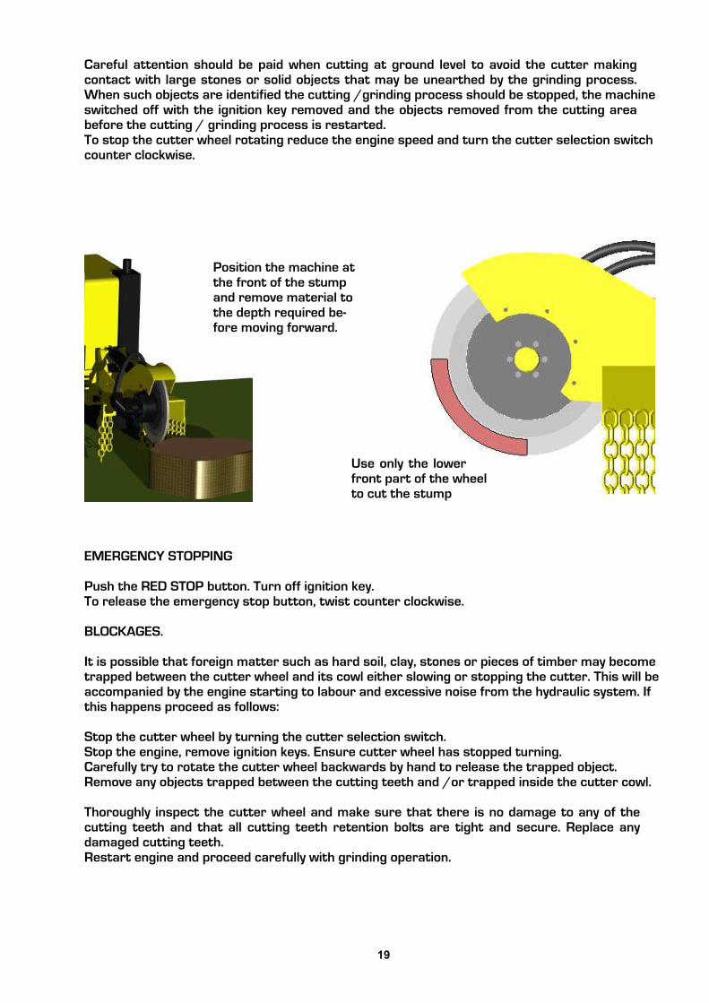
Careful attention should be paid when cutting at ground level to avoid the cutter making contact with large stones or solid objects that may be unearthed by the grinding process. When such objects are identified the cutting /grinding process should be stopped, the machine switched off with the ignition key removed and the objects removed from the cutting area before the cutting / grinding process is restarted.To stop the cutter wheel rotating reduce the engine speed and turn the cutter selection switch counter clockwise.
EMERGENCY STOPPING
Push the RED STOP button. Turn off ignition key.To release the emergency stop button, twist counter clockwise.
BLOCKAGES.
It is possible that foreign matter such as hard soil, clay, stones or pieces of timber may become trapped between the cutter wheel and its cowl either slowing or stopping the cutter. This will be accompanied by the engine starting to labour and excessive noise from the hydraulic system. If this happens proceed as follows:
Stop the cutter wheel by turning the cutter selection switch.Stop the engine, remove ignition keys. Ensure cutter wheel has stopped turning.Carefully try to rotate the cutter wheel backwards by hand to release the trapped object.Remove any objects trapped between the cutting teeth and /or trapped inside the cutter cowl.
Thoroughly inspect the cutter wheel and make sure that there is no damage to any of the cutting teeth and that all cutting teeth retention bolts are tight and secure. Replace any damaged cutting teeth.Restart engine and proceed carefully with grinding operation.
Use only the lower front part of the wheel to cut the stump
Position the machine at the front of the stump and remove material to the depth required be-fore moving forward.

20
11 12 13 14 15 16
1. Blank (future requirements)2. Engine stop switch3. Blank (future requirements)4. Cutter switch with safety cover5. Micro speed selection switch6. Green LED7. Emergency stop8. Red LED9. On/Signal/Freq shift10. DANGER11. Arm lift / lower lever12. Left track forward / back13. Blank (future requirements)14. Variable width 15. Right track forward / back16. Slew left right
1 4 2 3 5 6 7 8 9 10
Switch (2) will cut the engine on the machine when pushed either left or right. The control unit must be ON and synchronized in order for this or any other controls to work.Levers (11, 12, 13, 14, 15, 16) are all proportional and operate in the same way as described earlier in the manual. Switches 1,3 and lever 13 are used either for spares or future requirements.
Radio Control (option)
Unauthorized tampering with the radio control system automatically invalidates warranty
The radio control unit is highly sophisticated and offers fine control to the movements of the machine. Fine tuning of the controls can be made only by a qualified technician or under his instruction.
The manoeuvre levers give fully proportional operation and are sprung loaded to return to zero position, i.e. "dead-man's-handle". When the manoeuvre levers are moved from zero position the respective hy-draulic function starts to operate slowly and increases in speed as the lever is moved further from zero position and vice versa as the lever is moved back towards zero position.
For safety reasons all manoeuvre levers must be in their zero/neutral positions for a start-up to be made. If any lever is not in its zero/neutral position during start-up, the control unit will blink and beep the same number of times as the number of the lever to indicate which manoeuvre lever is faulty. The control unit can be used but the faulty lever will be locked and disengaged. (eg. if it beeps and blinks five times, it is the 5th lever from the LEFT which is faulty or giving the problem signal).
The micro speed button (5) slows down all the movements. This return sprung switch can be used to reduce the operating speed. With impulses from the sprung loaded toggle switch to the left, towards ON ( tortoise), reduces speed.Movement of the switch to the right, towards OFF (hare), will produce 100% movement once again. Green LED : Flashing - speed reduction. Not flashing - normal speed .
The large red emergency stop button (7) turns off the radio control unit when pushed in. It also stops the cutter wheel. IT DOES NOT STOP THE ENGINE ON THE MACHINE. The main emergency stop switch is located on the machine. Twist the switch (7) clockwise until it springs out, then push the On button (9) to turn the unit on. The red LED light (8)will show that the unit is on.
DANGER
Switch (4) is the cutter selection switch. This must be in the off position to start the machine.

21
OPERATING INSTRUCTIONS
Place a newly charged battery in the radio control unit. Start the grinder at the main ignition on the machine. Twist out the emergency stop switch on the radio control unit.
Switch (4) is the cutter selection switch. This must be in the off position.Press ON/SIGNAL/FREQ.-SHIFT (9), and the red LED will light continuously.The grinder is now ready for operation. The operator must be aware of all manoeuvre lever and switch functions before operation is started.The emergency stop on the control unit stops all operations from the unit. The emergency stop on the machine is the main emergency stop switch which also stops the engine.The switch (2) on the control unit stops the engine but the control unit must be on and in signal.The emergency stop on the control unit should always be in the depressed position whenever the unit is not in use. This applies even for short stoppages, for example, if the operator wishes to move.
Stand at least 3 metres from the machine if possible. If the cutter wheel of the machine is at position 12 on a clock in plan view, the best position to stand is either 10 or 2.Make sure nobody else is within 20 metres of the machine.Wear all PPE as described earlier in the manual.Only engage wheel when it is safe to do so.Follow operating instruction set out earlier in this manual for grinding.When finished switch off cutter wheel with button (4) and then switch off engine with button (2). Then push red stop button on the radio control unit. Then turn off the ignition on the machine.Store the radio control unit in a safe, dry place away from vibration, dust and high temperatures.
Control CabinetOpen the control cabinet/cowl door to access the lever control, radio receiver and battery charger.On the right hand side of the receiver is a switch, plug socket and some LED lights. The switch should remain in the radio control position at all time, which is towards the door.The plug (2) is for attachment of the cable for operation if the radio controls fail. It is also used for set-ting up the controls for fine adjustment.The battery charger charges the spare battery whilst the machine is running.
1 2 3 4 5 6 7 8 91. Spare battery and charger. 2. Radio control on switch. 3. Plug for cable use4. Manual lift lower lever5. Manual slew lever left/right6. Manual variable width lever7. Manual left track forward/back8. Manual right track forward/back9. Cutter engage/disengage switch for use during man-ual operation. Must be disengaged to start machine.
It is highly recommended that use of the manual controls is only as a last resort to finish a job if the remote controls packs up and the controls with the use of the cord also fails.
BATTERY CHARGER AND BATTERY CHARGING.
There are two chargers available with the machine. One is located inside the control cabinet. The other option is 240V. The battery pack is rechargeable and of Nickel Cadmium (NiCd) type.The normal charging time for an empty uncharged battery, is approximately 12-14 hours.The battery charger is constructed so that no damage will occur from long continuous charging.The batteries effective operation time is about 8 hours on one charge.When the battery is approaching time for charging, the control unit beeps three ( 3 ) times as a warning and at the same time the LED starts to blink on the control unit. The battery must be used until the LED goes out, after which it can be changed. If the battery capacity is too LOW the control unit cannot be activated.
In order to reduce battery loading and for safety reasons, the control unit is turned off automatically, after the unit has been idle for more than approximately five minutes.

22
MAINTENANCE.
Always immobilise engine, let engine cool down and remove ignition keys before undertaking any maintenance work on the machine.
VIBRATION
Stump grinders are machines that are subject to vibration. Be aware that vibration can work nuts and bolts loose. Check periodically all fixings for security.
PARTS
Only fit genuine MultiTip cutters and retaining bolts.Only fit genuine engine spares.Only fit genuine Predator stump grinder spares. Failure to do so will result in the invalidation of the warranty and may result in damage to the grinder, personal injury or even loss of life.
SAFETY
When maintaining your engine refer to the appropriate COSHH sheets from your suppliers.
GENERAL CLEANING.
Keep the stump grinder and engine clear from excessive dust, wood chippings and debris build up especially around the fuel filler cap, hydraulic oil tank fillers, engine bay and battery area. Cleaning should be done with a stiff brush or cloth. DO NOT USE steam cleaners, water jets, or highly flammable liquids to clean the machine.
CAUTION
CAUTION
DANGER
DANGER
WARNING
SERVICE SCHEDULE.
DAILY CHECKS BEFORE STARTING
Check engine oil - Top up if necessary. Refer to MSDS sheets from your oil supplier and engine manual.
Check hydraulic oil level. - When the stump grinder is on level ground the oil should show near the bottom of the gauge.
Check for engine oil / hydraulic oil leaks.
Check fuel level: To avoid condensation build up in fuel tank, keep tank full.
Check access covers and guards are securely fitted.
Check and adjust if necessary belt tightness from engine to clutch.
1. Hydraulic filler / filter2. Fuel filler3. Engine Oil filler4. Oil bath air filter5. Fuel filter6. Engine oil drain
1
2
3
4
5
6

23
Check tracks for correct tensioning and damage.
Check condition of cutters. Make sure that all cutter retaining bolts are tight and that there is nodebris that may break loose when the cutter is started.
Make sure wheel is tight, there is no wobble and it turns freely.Check and clean air filter and remove any debris from within the engine covers .
Apply two pumps of grease to the hub at the grease point at the centre of the wheel.
25 HOUR FIRST SERVICE (To be repeated every 25 hours)Perform all the daily checks.Check engine mounts making sure nuts are tight.Check round machine make sure nothing is working loose.Check tracks for correct tensioning and damage.Refer to engine manual for cleaning of air cooling system.Check and adjust if necessary belt tightness from layshaft to cutter head.
50 HOUR FIRST SERVICE.
Repeat 25 hour service.Change engine oil and filterChange fuel filtersChange hydraulic oil and filterCheck fuel pipes and clamp bands.
100 HOUR FIRST SERVICE.
Repeat standard 50 hour service. (inc 25 hour service)Check battery electrolyte level-Refer to COSHH safe batteries – supplied.Change oil in track drive gearbox.Grease undercarriage widening pins and slides.
EVERY 100 HOUR STANDARD SERVICE. (To be repeated every 100 hours of use.)
50 Hour standard service. (inc 25 hour service).Check battery electrolyte level-Refer to COSHH safe batteries – supplied.Grease undercarriage widening pins and slides.

24
SERVICE & MAINTENANCE INSTRUCTIONS.
SPARES SUPPLY.
All spares required for the stump grinder can be purchased direct from the dealer from whom the machine was purchased.
CHECKING FUEL LEVEL.
Do not smoke when refuelingKeep fuel away from naked heat sources. Wipe up any spillagesDiesel fuel can be injurious to the skin, wash thoroughly on completion of refueling.Refer to engine manufacturers instructions.
FILLING
The fuel tank should be kept as full as practicable to prevent water condensation and should not be allowed to run dry. Take care to ensure water does not contaminate the fuel. Scrupulous cleanliness should be observed at all times. The fuel injection equipment is made to very fine tolerances and even the smallest particle of dirt entering the system can cause damage.Add more fuel if required ensuring area around filler cap is clean.Refit fuel cap.
CHANGING FUEL FILTER.
Change inline fuel filter by loosening clips, removing and replacing new filter. Be sure to insert the new filter with the arrow in the direction of the flowMain filter – see engine manual.Bleed fuel system - refer to engine manual.Close engine cover and redo engine cover retention clips.Run and test.
CHECKING ENGINE OIL.
See engine manualIn order for the engine to function properly, maintain the oil at the proper level and change the oil and oil filter in accordance with the maintenance schedule. Not only do dirt and metal particles collect in the oil, but the oil itself loses its lubrication quality if used for too long.
REVVING ENGINE
Revving the engine straight from a cold start before the oil has had chance to circulate to every part of the engine can cause engine seizure. Allow the engine to run at no more than fast idle speed until warm.
Over filling the engine with oil can cause serious damage.
CAUTION
IMPORTANT
IMPORTANT
WARNING

25
CHANGING HYDRAULIC OIL FILTERS.There are two hydraulic filters on this machine. One suction (90 micron) located within the main tank and a 25 micron return filter located in a housing on top of the hydraulic tank.The hydraulic oil filters must be changed on a yearly basis regardless of use or 10 hours after any kind of servicing to the hydraulic system.
DANGER
OIL CHANGING - See engine manual
Undo oil drain plug located on the end of a hose at point (9)Drain oil into large container.Replace oil drain plug and tighten.Refill through point (6). Use the dipstick (7)to check level.Do not overfill.
CHANGING ENGINE OIL FILTER - See engine manual.
After draining oil, undo filter near battery Replace filter with new and tighten.Refill with oil to level on dip stick.
6. Oil fill up point7. Oil dipstick and filler8. Engine fuel filter9. Oil drain hose
CHANGING HYDRAULIC OIL
The hydraulic tank (14)
Place a clean dry container under the drain plug (11) and loosen until hydraulic fluid starts to drain into the container. The container should be capable of holding approximately 40 litres.Thoroughly clean area around the filter cap (15) before unscrewing to avoid oil contamination.
When fluid has stopped draining remove filter from housing (15) and replace with new. Replace cap.
Re-tighten plug and refill hydraulic system via filler cap (15) to the middle of the level gauge.
10. Fuel tank11. Drain plugs12. Battery13. Oil filter14. Hydraulic tank15. Return filter
6
7
8
9
10 11 12 13 14 15

26
GREASING CUTTER WHEEL BEARING.
There is a grease nipple provided on the outside of the cutter wheel hub next to the hydraulic motor. Apply two shots of grease from a standard grease gun.
BLUNT TEETH
Using the stump grinder with blunt cutters will over stress the cutter wheel and cause the cutter wheel bearings to fail prematurely.
The cutter wheel bearings are a serviceable part and should be replaced on a regular basis. It is recommend the bearings are changed yearly for optimum performance.
If the bearings start to make a rumbling noise or a high pitched whine expert advice should be sought as this could be the first signs of bearing failure.
ELECTRICAL.
There is a main fuse located in the control box near the emergency stop button. This controls the main 12 V dc supply to the complete electrical system.
Failure of the fuse is indicative of a fault in the electrical system and the machine should be returned to the dealer from whom the machine was purchased or to Predator so that the cause of the fault can be found and safely rectified. To simply replace the fuse without investigating the cause of failure and not carrying out the correct rectification work could be dangerous and detrimental to the safe operation of the stump grinder.
FURTHER INFORMATION
ANY FURTHER TECHNICAL INFORMATION CONCERNING REPAIRS, SERVICING OR MAINTENANCE CAN BE OBTAINED FROM YOUR SUPPLYING DEALER.
CAUTION
NOTE
NOTE

27
CLUTCH AND BRAKE
Burnishing in Running In
When a field replacement of the P26 clutch occurs, the new clutch should be burnished and ideally run-in. If this isn’t undertaken properly it will incur excessive heat in the first few hours of use and conse-quently premature failure.
It is standard that electro magnetic clutches need burnishing in and this is achieved by causing it to slip momentarily several times for short periods without generating too much heat.
Burnishing in is undertaken as below. Running In, although not essential, is recommended.
Ensure belts are at the correct tension before starting each procedure.
Burnishing1. Start the engine2. Set throttle to Low3. Engage cutter wheel for 2 seconds4. Disengage cutter wheel for 2 seconds5. Repeat steps 3 & 4 five times (no more).6. Turn off engine and leave for at least 5 minutes to cool.
When the clutch has cooled, repeat the whole process twice more. On each repeat, make sure no more than 5 “engage / disengage” cycles are made and that the clutch is left to cool in between. (There are therefore 15 cycles in 3 batches of 5.)
Running InTo ensure maximum clutch life a short running-in period is recommended when the Predator 26 is first used.
Grind as normal for approximately 5 minutes, then disengage the cutter wheel and leave for at least 5 minute to cool. Repeat up to 5 times.
MaintenanceThe gap between the clutch plates should be approximately 1mm. If this increase with wear it is possible that the clutch won’t engage. If this occurs, remove one of the spacer shims located on the shaft be-tween the plates.The brake can be adjusted by loosening the grub screws and relocating the disc on the lay shaft. Then re tightening the grub screws. An even gap of no more than 1mm is required. MAKE SURE THE BRAKE WORKS BEFORE USE.
Check and adjust if necessary belt tightness from layshaft to cutter head.Remove rubber guard, then arm guard. Loosen the remaining 2 head bolts. Loosen cam locking nut. Turn cam until belt is tight. Tighten locking nut. Reassemble.
Check and adjust if necessary belt tightness from engine to clutch.Loosen the 4 large locking nuts and tighten belts with the jacking screw at the rear of the machine. Then re tighten the 4 large locking nuts.
The cutter head and lay shaft assembly are modular and can be ordered complete as a reconditioned unit if required.
Clean fuel is essential for the operating and reliability of he machine. Always use the correct in-line fuel filter supplied from your local dealer or Predator.

28
Maintenance Of Your Multi-Tip System
1. Remove bolt and tap behind tooth
with a small hammer. Avoid hitting tips. Use safety goggles.
2. The keeper plate and tooth can be
separated once out of the slot.Check the groove in the top of thekeeper plate and the edges underneath that locate with the tooth. If these are damaged, replace.
Congratulations for purchasing your Multi-Tip stump grinding cutting system.
Please look after this system as setout below to insure a long and trouble free life span of the wheel and the components.
Safety is paramount. Please take note ofall the enclosed recommendations andsafety notes overleaf.
Tip - The leading teeth that are furthest
from the centre of the wheel do most of thecutting. By changing these as soon as they become blunt, you can re-use them in non-leading positions.

29
3. Check the condition of the slot.
If it is badly worn, change wheel.
4. Check threads in Insert and on Bolt.
If damaged, replace. If re-using, make sure they are clean and free from dirt.
The bolt can be re-used up to five times before it needs replacing, providing it isn’t damaged.Only use bolts supplied by Multi-Tip.
6. Make sure all surfaces are clean and
free from dirt. Re-fit the threaded insert, then the new tooth and keeper block together. Tap the front of the keeper block until it is located. Insert the bolt and wind up to a torque setting of 55Nm (40 ft-lb) After ten minutes of use stop and check bolt tightness.
If the assembly can not be tightened sufficiently into the wheel, do not use.
Never use this system without allcomponents in place and secure.
Keeper Block
5. Check condition of keeper plate.
If badly worn or damaged, replace. Replace tooth with new.
MultiTip Tooth
Nylok Bolt
Threaded Insert

30
MAINTENANCE OF TRACKED UNDERCARRIAGE
RUBBER TRACK TENSION
When the tracked undercarriage is lifted the rubber track must sag 10-15 mm. When tension decreases it must be re-tightened to prevent the track from coming off.Do not over tighten. If you continue to pump grease into the cylinder once the track is already tight, you will compress the cylinder spring and cause excessive damage.
CORRECT INSPECTION AND MAINTENANCE PROCEDURES.
Always perform maintenance on a solid and level surface.
Never grease or lubricate or perform maintenance on the machine while it is in motion.Solidly support the undercarriage if it needs to be lifted up for maintenance.Use great care when maintaining the hydraulic system since oil is very hot when the machine has just finished working.
Circuits are under high pressures even when the machine is not working. Keep all components properly installed and in good condition.Immediately repair all damage and replace worn or broken parts.Remove any build-ups of grease, oil or debris.Check for oil leaks and /or damaged hydraulic hoses.Use recommended lubricants. Do not mix different brands of lubricants.Use only original spare parts.
Keep undercarriage widening cylinder and track-stretcher grease nipples clean.Intervals for periodic maintenance are indicated for normal work conditions. If the tracked undercarriage is used in severe work conditions then maintenance must be performed at shorter intervals.
Dispose of lubricants in an ecologically safe way. Thoughtless disposal of lubricants can damage the environment. Become familiar with local anti-pollution laws and regulations before disposing of lubricants.Use suitable containers when draining lubricants. Do not use beverage or food containers that might tempt someone to drink from them. Never pour lubricants on the ground or in a canal, pond or watercourse. Comply with current environmental protection regulations when disposing of lubricants.
GEAR OIL
Avoid using oils with different characteristics and brands
CHOICE OF TYPE OF REDUCTION UNIT OILWe recommend, for reduction units, using gear oils with E.P. additives and viscosity class according to ISO VG 150 or SAE 80W/90.
When temperature variation ranges are very high we recommend using synthetic oils with E.P. properties and minimum 165 viscosity index and viscosity class VG
IMPORTANT

31
TRACK LOOSENING / TIGHTENING PROCEDURES.
The grease contained in the hydraulic track is pressurized. Never loosen grease valve (74) for more than one turn. If the valve is loosened too much you risk expelling grease under pressure and possible serious injury to the machine operator. Also never loosen grease nipple (73).
Remove gravel or mud from between the sprocket and the track.
Remove the screws and take off cover (68) to access the adjustment system.To loosen the track turn valve (74) counter-clockwise no more than one turn. One turn of valve (74) is sufficient for loosening the track.
If grease does not start to drain out then slowly rotate the track.
62. Gearbox drain plug63. Gearbox filler plug64. Gearbox65. Drive Sprocket66. Rubber track67. Roller
73 74 68Tighten the valve (74) by turning clockwise till tight. Clean all traces of extruded grease.To tighten the track connect a grease gun to grease nipple (73) and pump grease until the track tightens so that there is 10-15 mm of sag. Then stop
FRONT IDLER LOCKING
It is not normal for the track to remain tight after turning valve 1 counter-clockwise or for it to remain loose after introducing grease into grease nipple 2. Never try to remove the tracks or disassemble the track-stretching cylinder since pressure of the grease inside the track is extremely dangerous.
62 63 64 65 66 67 68 69 70 71 72
68. Adjuster cover plate69. Nylon guide block70. Side frame71. Roller bolt72. Front idler wheel73. Grease nipple74. Grease valve
DANGER

32
REMOVING THE RUBBER TRACK.
Stop your machine on a solid and level surface. Jack up side of machine under main frame and support it in safe condition.
Remove the cover plate (68) on side of track frame that gives access to the adjustment system.
To loosen a track slowly unscrew valve (74) counter-clockwise for no more than one turn. One turn of valve (74) is sufficient for loosening the track.If grease does not start to drain out then slowly rotate the track.
Insert 3 steel tubes in the space between the rollers and the tracks. Rotate the driving gear in reverse so that the steel tubes proceed with the track and contract the front idler wheel. Exercise force sideways to slide the track and lift it off the front idler wheel.
INSTALLING THE RUBBER TRACK.
Make sure that you are always in safe conditions with the machine lifted before performing the track installation operation.
Mesh the track links in the sprocket and place the other end of the track on the front idler wheel.Rotate the driving gear in reverse slowly and push the track soles into the frame Position the track using a steel tube and turn the driving gear again.Make sure the track links mesh correctly with the sprocket and with the front idler wheel.Adjust track tension as set out previously. Replace cover and lower back onto the ground.
UNDERCARRIAGE GREASE POINTS
Perform this maintenance procedure every 100 work hours, using lithium grease with EP2 consistency.
Clean grease nipples before connecting them to the grease gun.Clean all grease that exits out after greasing.
Lubrication should be at more frequent intervals if the tracked undercarriage is used in particularly severe operating conditions.
Grease points for the tracked undercarriage widening cylinder pins can be found when tracks are extended out. Grease more regularly if working in dusty or wet conditions.
WARNING
IMPORTANT
WARNING

33
The structure of the rubber track is shown above. The steel cables and metal core are embedded in the rubber. The carved profiles function gives stability on soft terrain. The wheel guides, located on the inside of the track, preventing the track from sliding off the guide rollers.
BREAKAGE OF STEEL CABLES.
Excess track tension can cause steel cables to break in the following conditions:When stones or foreign matter accumulate between the track and the undercarriage frame.When the track slips off its guide system.In case of great friction such as rapid changes in direction.
BREAKAGE OF METAL CORES.
Excess track tension can cause the metal cores to bend or break just like the steel cables as stated above.
Other causes include:Improper contact between track and sprocket.Rotation of internal rollers.Operation on sandy terrain.
MAINTENANCE OF DRIVE GEARED MOTORS.
CHECKING THE OIL LEVEL IN THE REDUCTION UNIT.
Stop the hydraulic geared motor with plugs (62 & 63) aligned horizontal. Remove the plugs and check that the oil level is up to their holes. Top up as necessary, filling through one of the holes and using the other to check the oil level.
REPLACEMENT OF OIL IN THE GEARBOX.
Replace the oil after the first 100 operating hours and then at subsequent 1000 hour Intervals. Proceed as follows to perform the replacement: - stop the reduction unit with the plugs (62 & 63) aligned vertically with (62) at the bottom - remove both plugs and drain out all the oil; -now position the plugs horizontally and fill the reduction unit through one hole, using the other to check the oil level.
METAL CORE SPROCKET HOLE CURVED PROFILE
CAUTION

34
General Assemblies, Sub Assemblies and Parts lists

35

36
P26 CUTTER HUB SUB-ASSY.
ITEM DESCRIPTION QTY PART-NUMBER.
1
STUB SHAFT 1 P-26-CA-002. STOCK ITEM.2
NUT 1 P-26-CA-004. STOCK ITEM.3
CLAMPING PLATE 1 P-26-CA-003. STOCK ITEM.4
5
1
2
3
11
8
SEAL. 125mm x 150mm x 12mm. 1 P-26-SL-001. STOCK ITEM.
6
9
GREASE NIPPLE. 1/8 BSP. 1
CUTTER HUB 1 P-26-CA-001. STOCK ITEM.
RECTANGULAR KEY STEEL. 1 P-26-CA-005. STOCK ITEM.
B-M8/22 8.8 STOCK ITEM.4SOC HD CAP SCREW-M8 x 22LG.
6
7
DOUBLE ROW ANG CON BALL BRG 1 P-26-BE-004. STOCK ITEM.
11
14M PULLEY. 142.6 PCD. 32 TEETH. 1 P-26-PU-001. STOCK ITEM.
P-26-BS-001. STOCK ITEM.1TAPER LOCK BUSH. Ø50.
12
13
M6 x 16 LG SOC SET(GRUB) SCREW 3 B-M6/16CP 8.8 STOCK ITEM.
4
(ITEM 5)USING KEY STEELCUT AND FIT KEY
NOTE.7
8
9
13
12
SEE DRAWING No. P-26-27.FOR TORQUE SPECIFICATION
THREADS PRIOR TO TIGHTENING.LOCTITE 2701 TO BE APPLIED TO ALLNOTE.
P-26-27. TORQUE SPECIFICATIONS.P-26-GA. GENERAL ARRANGEMENT.
CONJUNCTION WITH DRAWING No'STHIS DRAWING TO BE READ IN
TIGHTEN NUT USINGPIN SPANNER ANDTHEN FIT CONE POINTGRUB SCREWS TO FIX NUT IN POSITION.
10 P-26-SL-002. STOCK ITEM.1SEAL. 100mm x 125mm x 12mm.
10
P-26-GN-001. STOCK ITEM.

37

38

39

40

41
DECALSID101 ID102 ID103 ID104
ID105
ID106
ID108
ID110
ID111
ID114
ID117
ID119
ID120
ID121
ID125
ID126
ID128
ID129
ID130
ID131
ID132
ID123
42
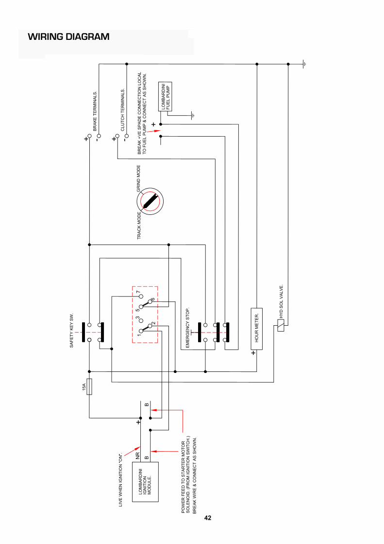
WIRING DIAGRAM

43
WIRING DIAGRAM Radio control

44
HYDRAULIC CIRCUIT

45
HYDRAULIC CIRCUIT Radio control

46

47
Warranty Validation Form - To be completed and sent back to Predator Manufacturing at the ad-
dress on the reverse of the manual within 14 days of putting machine into service.
Purchaser Information:
Company Name:.......................................................................................................................................................................
Contact:...................................................................................................................................................................................
Address:...................................................................................................................................................................................
Post Code:.................................................................................................................................................................................
Telephone numbers:.............................................................................................................................................................
Machine Information:
Model:............................................................................. Engine Type :..........................................................
Serial Number :........................................................... Serial Number :.....................................................
Dealer Information:
Dealer Name:................................................... Street Address:.........................................................................................
City: ...........................................................State:................................Post Code:..................................................................
I have been advised and instructed and will advise and instruct all users of this machine of the following:Operation and safety aspects of operating the equipment including:Not to reach into cutter wheel area.To stop machine and remove key before performing any type of maintenance.Not to operate the machine without the cutter wheel guard in place.Customer has been furnished with all parts and operators manuals.Customer has been instructed on equipment maintenance schedules and procedures.Customer has been advise that the engine or power unit that is used on this machine is warranted by the engine manufacturer and Predator. All engine warranty issues should be addressed to the local engine dealer.Customer understands the importance of air and oil filter maintenance, and the importance of staying within the an-gleof operation of the engine. If either of these is not adhered to, the engine warranty is VOID.All operation and warning decals are properly displayed on equipment.Customer understands it is his responsibility to train all operators on operator safety.
I have inspected this equipment and find it in good working condition. To the best of my knowledge, the customerand his personnel are aware of the above procedures.
Date: _______________ Signed: ____________________________________
Dealer RepresentativeThe equipment has been thoroughly checked by the above named dealer representative, and I amsatisfied with his instructions.
Date: ________________ Signed: ___________________________________Purchaser

48

49
WARRANTY STATEMENT.
The Predator Tree Stump Grinder is guaranteed free from defects caused by faulty materials or workmanship for a period of 12 months from the date of purchase.
Warranty does NOT apply if abuse or neglect causes damage to the machine or if it has been improperly maintained.
This warranty takes effect upon delivery to the original retail purchaser. The manufacturer, at its option, will replace or repair, at a point designated by the manufactur-er, any parts which appear to have been defective in material or workmanship. The manufac-turer is not responsible for consequential damages.
The owner is responsible for all regular maintenance as explained in the operators’ manual. Neglect in regular maintenance or failure to replace normal wear items such as teeth, keepers, bolts, lubrication oils, filters, belts, bearings, etc. may void warranty.
This warranty is expressly in lieu of any other warranties, expressed or implied, including any implied warranty or merchantability of fitness for a particular purpose and of any non-contractual liabilities including product liabilities based upon negligence or strict liability. The manufacturer will not be liable for consequential damages resulting from breach of war-ranty.
The manufacturer will not reimburse the customer or dealer labour cost incurred for installing “bolt-on” or “slip-on” items, such as pumps and motors, bearings, belts, pulleys, etc. The manufacturer will provide replacement parts at no cost to the customer for defective parts during the warranty period.
Defective parts must be returned to the manufacturer. It will be the customers’ responsibility to install the replacement parts unless arrangements are made with the selling dealer. The manufacturer will not reimburse travel cost to servicing dealer unless prior approval has been obtained from the manufacturer. It is the customers responsibility to deliver the machine to dealers facility, unless other arrangements have been agreed to between the selling dealer and the customer. The manufacturer may elect, at its discretion, to reimburse reasonable labour cost to cus-tomer or dealer for major defect repairs. Prior approval must be obtained from the manufacturer
IT IS NECESSARY TO RETURN THE WARRANTY VALIDATION FORM TO PREDATOR WITHIN FOURTEEN (14) DAYS FROM DELIVERY DATE TO VALIDATE THIS WARRANTY.
MACHINES USED FOR LEASE OR RENTAL - WARRANTY IS LIMITED TO 90 DAYS.
Engines are warranted by the engine manufacturer and their dealers and not by Predator or it’s dealers. See engine manuals for details.
NORMAL WEARWarranty will not cover repair when normal use has exhausted the life of a part.
For purposes of this warranty statement the warranty will apply to the original purchaser only and is not transferable.
This warranty statement does not affect your Statutory Rights.
PRODUCTION DIVISION, PREDATOR, HENLEY ON THAMES.


