129
Safety Reports Series No.32 Implementation of Accident Management Programmes in Nuclear Power Plants
S a f e t y R e p o r t s S e r i e sN o . 3 2
I m p l e m e n t a t i o n o fA c c i d e n t M a n a g e m e n t
P r o g r a m m e s i n N u c l e a rP o w e r P l a n t s
IAEA SAFETY RELATED PUBLICATIONS
IAEA SAFETY STANDARDS
Under the terms of Article III of its Statute, the IAEA is authorized to establish standardsof safety for protection against ionizing radiation and to provide for the application of thesestandards to peaceful nuclear activities.
The regulatory related publications by means of which the IAEA establishes safetystandards and measures are issued in the IAEA Safety Standards Series. This series coversnuclear safety, radiation safety, transport safety and waste safety, and also general safety (thatis, of relevance in two or more of the four areas), and the categories within it are SafetyFundamentals, Safety Requirements and Safety Guides.
Safety Fundamentals (blue lettering) present basic objectives, concepts and principles ofsafety and protection in the development and application of nuclear energy for peacefulpurposes.
Safety Requirements (red lettering) establish the requirements that must be met to ensuresafety. These requirements, which are expressed as ‘shall’ statements, are governed bythe objectives and principles presented in the Safety Fundamentals.
Safety Guides (green lettering) recommend actions, conditions or procedures for meetingsafety requirements. Recommendations in Safety Guides are expressed as ‘should’ state-ments, with the implication that it is necessary to take the measures recommended orequivalent alternative measures to comply with the requirements.
The IAEA’s safety standards are not legally binding on Member States but may beadopted by them, at their own discretion, for use in national regulations in respect of their ownactivities. The standards are binding on the IAEA in relation to its own operations and on Statesin relation to operations assisted by the IAEA.
Information on the IAEA’s safety standards programme (including editions in languagesother than English) is available at the IAEA Internet site
www-ns.iaea.org/standards/or on request to the Safety Co-ordination Section, IAEA, P.O. Box 100, A-1400 Vienna,Austria.
OTHER SAFETY RELATED PUBLICATIONS
Under the terms of Articles III and VIII.C of its Statute, the IAEA makes available andfosters the exchange of information relating to peaceful nuclear activities and serves as anintermediary among its Member States for this purpose.
Reports on safety and protection in nuclear activities are issued in other series, inparticular the IAEA Safety Reports Series, as informational publications. Safety Reports maydescribe good practices and give practical examples and detailed methods that can be used tomeet safety requirements. They do not establish requirements or make recommendations.
Other IAEA series that include safety related publications are the Technical ReportsSeries, the Radiological Assessment Reports Series, the INSAG Series, the TECDOCSeries, the Provisional Safety Standards Series, the Training Course Series, the IAEAServices Series and the Computer Manual Series, and Practical Radiation Safety Manualsand Practical Radiation Technical Manuals. The IAEA also issues reports on radiologicalaccidents and other special publications.

IMPLEMENTATION OF ACCIDENTMANAGEMENT PROGRAMMESIN NUCLEAR POWER PLANTS

The following States are Members of the International Atomic Energy Agency:
AFGHANISTANALBANIAALGERIAANGOLAARGENTINAARMENIAAUSTRALIAAUSTRIAAZERBAIJANBANGLADESHBELARUSBELGIUMBENINBOLIVIABOSNIA AND
HERZEGOVINABOTSWANABRAZILBULGARIABURKINA FASOCAMEROONCANADACENTRAL AFRICAN
REPUBLICCHILECHINACOLOMBIACOSTA RICACÔTE D’IVOIRECROATIACUBACYPRUSCZECH REPUBLICDEMOCRATIC REPUBLIC
OF THE CONGODENMARKDOMINICAN REPUBLICECUADOREGYPTEL SALVADORERITREAESTONIAETHIOPIAFINLANDFRANCEGABONGEORGIAGERMANYGHANA
GREECEGUATEMALAHAITIHOLY SEEHONDURASHUNGARYICELANDINDIAINDONESIAIRAN, ISLAMIC REPUBLIC OF IRAQIRELANDISRAELITALYJAMAICAJAPANJORDANKAZAKHSTANKENYAKOREA, REPUBLIC OFKUWAITKYRGYZSTANLATVIALEBANONLIBERIALIBYAN ARAB JAMAHIRIYALIECHTENSTEINLITHUANIALUXEMBOURGMADAGASCARMALAYSIAMALIMALTAMARSHALL ISLANDSMAURITIUSMEXICOMONACOMONGOLIAMOROCCOMYANMARNAMIBIANETHERLANDSNEW ZEALANDNICARAGUANIGERNIGERIANORWAYPAKISTANPANAMA
PARAGUAYPERUPHILIPPINESPOLANDPORTUGALQATARREPUBLIC OF MOLDOVAROMANIARUSSIAN FEDERATIONSAUDI ARABIASENEGALSERBIA AND MONTENEGROSEYCHELLESSIERRA LEONESINGAPORESLOVAKIASLOVENIASOUTH AFRICASPAINSRI LANKASUDANSWEDENSWITZERLANDSYRIAN ARAB REPUBLICTAJIKISTANTHAILANDTHE FORMER YUGOSLAV
REPUBLIC OF MACEDONIATUNISIATURKEYUGANDAUKRAINEUNITED ARAB EMIRATESUNITED KINGDOM OF
GREAT BRITAIN AND NORTHERN IRELAND
UNITED REPUBLICOF TANZANIA
UNITED STATES OF AMERICAURUGUAYUZBEKISTANVENEZUELAVIETNAMYEMENZAMBIAZIMBABWE
The Agency’s Statute was approved on 23 October 1956 by the Conference on the Statuteof the IAEA held at United Nations Headquarters, New York; it entered into force on 29 July 1957.The Headquarters of the Agency are situated in Vienna. Its principal objective is “to accelerate andenlarge the contribution of atomic energy to peace, health and prosperity throughout the world’’.
© IAEA, 2004
Permission to reproduce or translate the information contained in this publication may beobtained by writing to the International Atomic Energy Agency, Wagramer Strasse 5, P.O. Box 100,A-1400 Vienna, Austria.
Printed by the IAEA in AustriaMarch 2004
STI/PUB/1167

IMPEMENTATION OF ACCIDENTMANAGEMENT PROGRAMMESIN NUCLEAR POWER PLANTS
SAFETY REPORTS SERIES No. 32
INTERNATIONAL ATOMIC ENERGY AGENCYVIENNA, 2004

IAEA Library Cataloguing in Publication Data
Implementation of accident management programmes in nuclear powerplants. — Vienna : International Atomic Energy Agency, 2004.
p. ; 24 cm. — (Safety reports series, ISSN 1020–6450 ; no. 32)STI/PUB/1167ISBN 92–0–113803–2Includes bibliographical references.
1. Nuclear power plants—Accidents. 2. Emergency management.3. Nuclear reactor accidents. I. International Atomic Energy Agency.II. Series.
IAEAL 04–00351

FOREWORD
Many Member States operating nuclear power plants (NPPs) are at present developing accident management programmes (AMPs) aimed at theprevention and mitigation of severe accidents. Such developments are in com-pliance with a revised set of IAEA Safety Standards, in particular with SafetyRequirements on design, on operation, and on preparedness and response fora nuclear and radiological emergency. However, the level of implementationvaries significantly between NPPs. The exchange of experience and best prac-tices can contribute considerably to the quality and facilitate the implementa-tion of AMPs at the plants.
Various IAEA activities assist States in the area of accident management.Several publications have been developed which provide guidance and supportin the establishment of accident management at NPPs. Various technical meet-ings and workshops are also organized to provide a forum for presentationsand discussions and to share experience in the development and implementa-tion of AMPs at individual NPPs.
This report provides a description of the elements which should beaddressed by the team responsible for preparation, development and imple-mentation of a plant specific AMP at an NPP. The issues addressed include for-mation of the team, selection of accident management strategies, safety analy-ses required, evaluation of the performance of plant systems, development ofaccident management procedures and guidelines, staffing and qualification ofaccident management personnel, and training needs. The report is intended tofacilitate the work to be done by NPP operators, utilities and their technicalsupport organizations, but it can also be used for the preparation of relevantnational regulatory requirements.
This Safety Report serves as a basis for other, more specific publications.It also provides the basis for the safety service on Review of AccidentManagement Programmes, which is offered to Member States to perform anobjective assessment of the status of various phases of AMP implementation ascompared with international experience and practices.
The IAEA officer responsible for this publication was J. Mišák of theDivision of Nuclear Installation Safety.

EDITORIAL NOTE
Although great care has been taken to maintain the accuracy of information con-tained in this publication, neither the IAEA nor its Member States assume any responsi-bility for consequences which may arise from its use.
The use of particular designations of countries or territories does not imply anyjudgement by the publisher, the IAEA, as to the legal status of such countries or territo-ries, of their authorities and institutions or of the delimitation of their boundaries.
The mention of names of specific companies or products (whether or not indicatedas registered) does not imply any intention to infringe proprietary rights, nor should it beconstrued as an endorsement or recommendation on the part of the IAEA.

CONTENTS
1. INTRODUCTION . . . . . . . . . . . . . . . . . . . . . . . . . . . . . . . . . . . . . . . . . 1
1.1. Background . . . . . . . . . . . . . . . . . . . . . . . . . . . . . . . . . . . . . . . . . . . 11.2. Objective . . . . . . . . . . . . . . . . . . . . . . . . . . . . . . . . . . . . . . . . . . . . . 21.3. Scope . . . . . . . . . . . . . . . . . . . . . . . . . . . . . . . . . . . . . . . . . . . . . . . . 41.4. Structure . . . . . . . . . . . . . . . . . . . . . . . . . . . . . . . . . . . . . . . . . . . . . 4
2. BASIC FEATURES OF AMPs . . . . . . . . . . . . . . . . . . . . . . . . . . . . . . . 6
2.1. Objectives and background of accident management . . . . . . . . 62.2. Preventive and mitigatory features of accident management . 72.3. Accident progression and degrees of severity . . . . . . . . . . . . . . 92.4. Assessment of vulnerabilities and capabilities . . . . . . . . . . . . . . 102.5. Accident management strategies . . . . . . . . . . . . . . . . . . . . . . . . . 112.6. Information needs . . . . . . . . . . . . . . . . . . . . . . . . . . . . . . . . . . . . . 122.7. Plant equipment performance and material support needs . . . 142.8. Procedures and guidelines . . . . . . . . . . . . . . . . . . . . . . . . . . . . . . . 162.9. Phases of the AMP . . . . . . . . . . . . . . . . . . . . . . . . . . . . . . . . . . . . . 17
3. PREPARATION OF THE ACCIDENT MANAGEMENTPROGRAMME . . . . . . . . . . . . . . . . . . . . . . . . . . . . . . . . . . . . . . . . . . . . 18
3.1. Team formation . . . . . . . . . . . . . . . . . . . . . . . . . . . . . . . . . . . . . . . 183.2. Familiarization . . . . . . . . . . . . . . . . . . . . . . . . . . . . . . . . . . . . . . . . 203.3. Selection and definition of an AMP . . . . . . . . . . . . . . . . . . . . . . 20
3.3.1. Procedures versus guidelines and degree of proceduralization . . . . . . . . . . . . . . . . . . . . . . . . . . . . . . . . . 21
3.3.2. Symptom based procedures and guidelines . . . . . . . . . . . 223.3.3. Coverage . . . . . . . . . . . . . . . . . . . . . . . . . . . . . . . . . . . . . . . . 223.3.4. Entry and exit bases and interfaces . . . . . . . . . . . . . . . . . . 23
3.4. Review of available safety analyses and specification offurther information needs . . . . . . . . . . . . . . . . . . . . . . . . . . 23
3.4.1. General . . . . . . . . . . . . . . . . . . . . . . . . . . . . . . . . . . . . . . . . . 233.4.2. Analyses needed for AMP development . . . . . . . . . . . . . . 243.4.3. Preliminary analysis for EOPs . . . . . . . . . . . . . . . . . . . . . . 253.4.4. Preliminary analysis for mitigatory severe accident
management actions . . . . . . . . . . . . . . . . . . . . . . . . . . . . . . . 26
3.5. Evaluation of the plant equipment and instrumentation performance . . . . . . . . . . . . . . . . . . . . . . . . . . . . . . . . . . . . . . . . . . 27
4. DEVELOPMENT OF AN AMP . . . . . . . . . . . . . . . . . . . . . . . . . . . . . 29
4.1. Selection and development of severe accidentmanagement strategies . . . . . . . . . . . . . . . . . . . . . . . . . . . . . . . . . 294.1.1. Selection of severe accident management strategies . . . . 294.1.2. Development of severe accident management
strategies . . . . . . . . . . . . . . . . . . . . . . . . . . . . . . . . . . . . . . . . 324.2. Development of accident management procedures
and guidelines . . . . . . . . . . . . . . . . . . . . . . . . . . . . . . . . . . . . . . . . . 334.2.1. Development and writing . . . . . . . . . . . . . . . . . . . . . . . . . . 334.2.2. Preparation of background material and
documentation . . . . . . . . . . . . . . . . . . . . . . . . . . . . . . . . . . . 354.3. Supporting accident analysis for development
of procedures and guidelines . . . . . . . . . . . . . . . . . . . . . . . . . . . . 364.3.1. Development analysis of EOPs . . . . . . . . . . . . . . . . . . . . . 364.3.2. Analysis for the development of severe accident
management guidelines . . . . . . . . . . . . . . . . . . . . . . . . . . . . 374.4. Determination of the needs for plant instrumentation,
equipment and material, and necessary upgrades . . . . . . . . . . . 384.5. Integration of procedures, guidelines
and the plant’s emergency arrangements . . . . . . . . . . . . . . . . . . 394.6. Verification and validation of procedures and guidelines . . . . 42
4.6.1. Verification . . . . . . . . . . . . . . . . . . . . . . . . . . . . . . . . . . . . . . 424.6.2. Validation . . . . . . . . . . . . . . . . . . . . . . . . . . . . . . . . . . . . . . . . 424.6.3. Supporting analysis . . . . . . . . . . . . . . . . . . . . . . . . . . . . . . . . 43
4.7. Specification of training needs . . . . . . . . . . . . . . . . . . . . . . . . . . . 444.8. Review of the AMP . . . . . . . . . . . . . . . . . . . . . . . . . . . . . . . . . . . . 444.9. Involvement of the regulatory body . . . . . . . . . . . . . . . . . . . . . . 45
5. IMPLEMENTATION . . . . . . . . . . . . . . . . . . . . . . . . . . . . . . . . . . . . . . . 45
5.1. Overview of the plant’s emergency organization . . . . . . . . . . . . 455.1.1. General . . . . . . . . . . . . . . . . . . . . . . . . . . . . . . . . . . . . . . . . . 455.1.2. On-site emergency organization . . . . . . . . . . . . . . . . . . . . . 465.1.3. Organizational aspects of implementation . . . . . . . . . . . . 485.1.4. Involvement of the regulatory body . . . . . . . . . . . . . . . . . . 48
5.2. Training . . . . . . . . . . . . . . . . . . . . . . . . . . . . . . . . . . . . . . . . . . . . . . 485.2.1. General . . . . . . . . . . . . . . . . . . . . . . . . . . . . . . . . . . . . . . . . . 48
5.2.2. Scope and means . . . . . . . . . . . . . . . . . . . . . . . . . . . . . . . . . 495.2.3. Skills of staff members . . . . . . . . . . . . . . . . . . . . . . . . . . . . . 49
5.3. Staffing and qualification . . . . . . . . . . . . . . . . . . . . . . . . . . . . . . . 515.4. Revisions to the AMP . . . . . . . . . . . . . . . . . . . . . . . . . . . . . . . . . . 52
APPENDIX I: PLANT DAMAGE STATES . . . . . . . . . . . . . . . . . . . . . 53
APPENDIX II: CANDIDATE HIGH LEVEL ACTIONS . . . . . . . . . . 57
APPENDIX III: COMPUTATIONAL AIDS . . . . . . . . . . . . . . . . . . . . . . 61
APPENDIX IV: TYPICAL PARAMETERS AND MECHANISMS USED FOR INITIATION OF PREVENTIVE AND MITIGATORY ACTIONS . . . . . . . . . . . . . . . . . 64
APPENDIX V: PREVENTIVE ACCIDENT MANAGEMENTACTIONS . . . . . . . . . . . . . . . . . . . . . . . . . . . . . . . . . . . . . 67
APPENDIX VI: REVIEW OF AN AMP . . . . . . . . . . . . . . . . . . . . . . . . . 75
APPENDIX VII: TRANSITION FROM THE EOP DOMAINTO THE SEVERE ACCIDENT MANAGEMENTGUIDANCE DOMAIN . . . . . . . . . . . . . . . . . . . . . . . . . 94
APPENDIX VIII: USE OF PSA IN SAMG DEVELOPMENT . . . . . . . 97
REFERENCES . . . . . . . . . . . . . . . . . . . . . . . . . . . . . . . . . . . . . . . . . . . . . . . . . 101
ANNEX I: SUMMARY OF INTERNATIONAL ACTIVITIES INSEVERE ACCIDENT MANAGEMENT . . . . . . . . . . . . . . 103
ANNEX II: OVERVIEW OF THE SEVERE ACCIDENT MANAGEMENT GUIDANCE APPROACH ANDIMPLEMENTATION IN SOME MEMBER STATES . . . 105
ANNEX III: TYPICAL TSC ORGANIZATION AT A BWRIN THE USA . . . . . . . . . . . . . . . . . . . . . . . . . . . . . . . . . . . . . . . 115
DEFINITIONS . . . . . . . . . . . . . . . . . . . . . . . . . . . . . . . . . . . . . . . . . . . . . . . . . 117
CONTRIBUTORS TO DRAFTING AND REVIEW . . . . . . . . . . . . . . . . 121

1. INTRODUCTION
1.1. BACKGROUND
According to the generally established defence in depth concept innuclear safety [1, 2], consideration in plant operation is also given to highlyimprobable severe plant conditions that were not explicitly addressed in theoriginal design of currently operating nuclear power plants (NPPs). Defencein depth is achieved primarily by means of four successive barriers whichprevent the release of radioactive material (fuel matrix, cladding, primarycoolant boundary and containment), and these barriers are primarily pro-tected by three levels of design measures: prevention of abnormal operationand failures (level 1), control of abnormal operation and detection of fail-ures (level 2) and control of accidents within the design basis (level 3). Ifthese first three levels fail to ensure the structural integrity of the core, e.g.due to beyond the design basis multiple failures, or due to extremely unlike-ly initiating events, additional efforts are made at level 4 to further reducethe risks. The objective at the fourth level is to ensure that both the likeli-hood of an accident entailing significant core damage (severe accident) andthe magnitude of radioactive releases following a severe accident are kept aslow as reasonably achievable. Finally, level 5 includes off-site emergencyresponse measures, with the objective of mitigating the radiological conse-quences of significant releases of radioactive material. The implementationof the emergency response is usually dependent upon the type and magni-tude of the accident. Good co-ordination between the operator and theresponding organizations is needed to ensure the appropriate response.
Accident management is one of the key components of effectivedefence in depth. In accordance with defence in depth, each design levelshould be protected individually, independently of other levels. This means,in particular, that accident management provisions should take place in anycase, even if all provisions within the design basis are adequate.
This report focuses on the fourth level of defence in depth, includingthe transitions from the third level and into the fifth level. It describes goodpractices and developments in Member States and is intended as referencematerial for NPPs, as well as an information source for other organizationssuch as regulatory bodies. It is a follow-up to the IAEA report on AccidentManagement Programmes in Nuclear Power Plants, published in 1994 [3],and reflects the considerable progress made since that time.
An overview of earlier IAEA efforts in the area of accident manage-ment and an outline of work in this area by the Organisation for Economic
1
Co-operation and Development (OECD) and the European Commission (EC)is contained in Annex I.
Various aspects of the prevention and mitigation of severe accidentshave been partially reflected in ‘traditional’ documents used for the operationof NPPs such as safety analysis reports, probabilistic safety analysis (PSA)studies (especially level 2 PSAs), emergency operating procedures (EOPs)and emergency plans. However, the importance of the issue requires the inte-gration of all available relevant plant specific information into a comprehen-sive set of consistent documents, the accident management programme(AMP). The exchange of experience and best practices can considerably facil-itate and contribute to the quality of such a document to be developed forindividual plants.
1.2. OBJECTIVE
The objective of this report is to provide a description of the elements tobe addressed by the team responsible for developing and implementing a plantspecific AMP at an NPP.Although it is intended primarily for use by NPP oper-ators, utilities and their technical support organizations, it can also facilitatepreparation of the relevant national regulatory requirements.
Severe accidents are addressed in a revised set of standards in the IAEASafety Standards Series, including the Safety Requirements publication onSafety of Nuclear Power Plants: Design [4], which supersedes the former Codeon the Safety of Nuclear Power Plants: Design (Safety Series No. 50-C-D (Rev. 1), issued in 1988). In these requirements it is stated that:
“Consideration shall be given to these severe accident sequences, usinga combination of engineering judgment and probabilistic methods, todetermine those sequences for which reasonably practicable preventiveor mitigatory measures can be identified. Acceptable measures need notinvolve the application of conservative engineering practices used insetting and evaluating design basis accidents, but rather should be basedupon realistic or best estimate assumptions, methods and analytical cri-teria. On the basis of operational experience, relevant safety analysisand results from safety research, design activities for addressing severeaccidents shall take into account the following:
(1) Important event sequences that may lead to severe accidents shall be iden-tified using a combination of probabilistic methods, deterministic methodsand sound engineering judgement.
2
(2) These event sequences shall then be reviewed against a set of criteria aimedat determining which severe accidents should be addressed in the design.
(3) Potential design or procedural changes that could either reduce the likeli-hood of these selected events, or mitigate their consequences, should theseselected events occur, shall be evaluated, and shall be implemented if reasonably practicable.
(4) Consideration shall be given to the plant’s full design capabilities, includingthe possible use of some systems (i.e. safety and non-safety systems)beyond their originally intended function and anticipated operating condi-tions, and the use of additional temporary systems to return the plant to acontrolled state and/or to mitigate the consequences of a severe accident,provided that it can be shown that the systems are able to function in theenvironmental conditions to be expected.
(5) For multiunit plants, consideration shall be given to the use of availablemeans and/or support from other units, provided that the safe operation ofthe other units is not compromised.
(6) Accident management procedures shall be established, taking into accountrepresentative and dominant severe accident scenarios.”
With reference to the Safety Requirements [4], this Safety Reportdescribes the AMP and elaborates on its preparation, development and implementation in any NPP. The report is based on developments that have been made in the accident management field worldwide.
The status of implementation of accident management varies widelythroughout the world. The process is determined mostly by national regulatoryrequirements.The accident management approach chosen also depends to someextent on plant design. More experience is available with the implementation ofpreventive measures than with mitigatory actions, but in some countries NPPshave already implemented both. Upgraded preventive accident management inthe form of modern, symptom based EOPs has either been implemented or is in preparation in most countries operating LWRs. Implementation of severeaccident management guidelines (SAMGs) has also commenced in numerouscountries. These efforts include control room (CR) reviews, upgrades of equip-ment and instrument displays, improvements to safety related equipment,and emergency plan enhancements. In some cases, the approach involves thedevelopment of generic guidelines by vendors, engineering consultants andowners groups, followed by adaptation of these guidelines by the individualplant to reflect its own specific design features. In other cases, AMPs are devel-oped specifically for each plant. Although many features are common to theimplementation of all AMPs, it is recognized that a variety of means may beused to achieve the same goals.
3

1.3. SCOPE
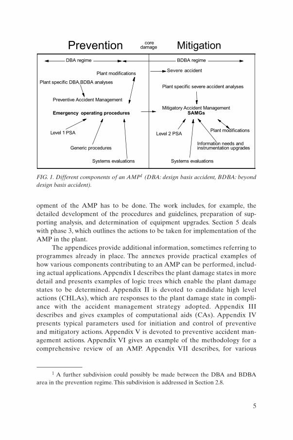
The relationship between different components of an AMP is illustratedin Fig. 1. Although many practical examples are taken from the applications forLWRs (PWR, BWR, WWER), the general guidance in this report can be usedfor any NPP.
This report focuses on SAMGs. Emergency operating procedures areaddressed on a more limited scale, with emphasis on those parts that are rele-vant for the later transition to SAMGs.
Both internal and external events are covered. A specific class of eventsis violent actions by third parties. Where the physical consequences of suchevents are comparable to those from other origins, they are also covered in this report. Preventive measures and/or the restoration of systems to serviceare in that case mostly dependent on physical protection measures which are,however, beyond the scope of this report.
The report concentrates on full power operational states: low power andshutdown states are not discussed. It is also limited to conditions under whicha certain amount of control over the main power plant functions still exists —no large scale disruption or destruction of the NPP is assumed.
The focus here is primarily on existing plants, i.e. plants which are eitherin operation or under construction. New plants, obviously, are not excludedfrom consideration; it is expected, however, that for new plants many severeaccident prevention and mitigation features will have already been included inthe design.
Accident analysis is typically also a significant component of the devel-opment of the AMP.The issue of accident analysis is covered by another IAEApublication [5] and is therefore only partially covered here.
1.4. STRUCTURE
This report consists of a main body, eight appendices and three annexes.The main body is subdivided into an introductory section and four additionalsections. Section 2 covers the basic principles of the AMP, including the speci-fication of its objectives, a short description of severe accident progression, pos-sible accident management strategies, and characterization of plant equipmentperformance under severe accident conditions.The detailed actions and projectsteps of the proposed AMP are divided into three phases: preparation, devel-opment and implementation. Section 3 discusses the actions to be taken duringthe first phase, mainly related to preparation and programme definition.Section 4 describes the second phase, in which most of the work on the devel-
4
opment of the AMP has to be done. The work includes, for example, thedetailed development of the procedures and guidelines, preparation of sup-porting analysis, and determination of equipment upgrades. Section 5 dealswith phase 3, which outlines the actions to be taken for implementation of theAMP in the plant.
The appendices provide additional information, sometimes referring toprogrammes already in place. The annexes provide practical examples ofhow various components contributing to an AMP can be performed, includ-ing actual applications. Appendix I describes the plant damage states in moredetail and presents examples of logic trees which enable the plant damagestates to be determined. Appendix II is devoted to candidate high levelactions (CHLAs), which are responses to the plant damage state in compli-ance with the accident management strategy adopted. Appendix IIIdescribes and gives examples of computational aids (CAs). Appendix IVpresents typical parameters used for initiation and control of preventive and mitigatory actions. Appendix V is devoted to preventive accident man-agement actions. Appendix VI gives an example of the methodology for acomprehensive review of an AMP. Appendix VII describes, for various
5
1 A further subdivision could possibly be made between the DBA and BDBAarea in the prevention regime. This subdivision is addressed in Section 2.8.
FIG. 1. Different components of an AMP1 (DBA: design basis accident, BDBA: beyonddesign basis accident).
regime
Prevention Mitigationcoredamage
DBA regime BDBA
Plant modifications accident
Plant specific DBA,BDBA analysesPlant specific severe accident analyses
Mitigatory Accident ManagementEmergency operating procedures
Preventive Accident Management
PSA Level 1
Generic procedures
Systems evaluations Systems evaluations
Information needs andinstrumentation upgrades
Level 2 PSAPlant modifications
Severe
SAMGs

approaches, how the transition from the EOP domain to the severe accidentmanagement domain can be achieved. Appendix VIII gives an overview ofthe use of PSA in the development of SAMGs.
Annex I gives an overview of earlier IAEA actions in this field, as well asthose of the OECD and the EC. Annex II gives a limited overview of severeaccident management applications in various Member States. Annex III pres-ents an example of the organization of a typical technical support centre (TSC)in an NPP in the USA.
2. BASIC FEATURES OF AMPs
2.1. OBJECTIVES AND BACKGROUND OF ACCIDENT MANAGEMENT
Depending on the level of defence in depth breached, the following arethe four main objectives of accident management:
(1) Prevention of the accident from leading to core damage,(2) Termination of core damage,(3) Maintaining the integrity of the containment for as long as possible,(4) Minimizing on-site and off-site releases and their adverse consequences.
The latter three items constitute the objectives of severe accident man-agement. It should be noted that objectives (2)–(4) may not be achieved solelyby plant personnel.
The first priority of nuclear safety is to prevent accidents in plants.However, it must be recognized that, although it is unlikely, those preventiveactions may fail. Hence it is appropriate to give attention to measures to con-trol the course of an accident in both the short and the long term, and to pre-vent or mitigate its consequences to the greatest extent possible.
It is important to develop plant specific EOPs and SAMGs to make bestuse of the systems available to halt the progression of an accident by protectionof the primary system boundary, the containment, and any additional systemsand structures that augment the functions of core cooling or containment of fis-sion products (FPs), such as filters, sprays, water pools and auxiliary buildings.The purpose is to reduce the fuel temperature and maximize the length and complexity of the pathway by which FPs would escape to the environment.
6

In order to optimize the management of an accident, the operating staffshould understand the mechanisms of reactor accidents and know how plantsystems can be used to control a developing situation. This should include allplant systems, both dedicated safety systems and non-safety related systems.Use of these systems and their components under accident conditions shouldbe anticipated, even outside their intended range of operation.
Although there are still questions which require further investigation, andthe fact that uncertainty associated with current research results remains large,the understanding of severe accident phenomena has reached a level at whichthe development of accident management measures is appropriate. Further,these research results permit improvements in new plant designs which canincrease the resistance of the plant to severe accidents, often at little cost. For anew plant design, for example, the geometry of the cavity beneath the reactorpressure vessel (RPV) can be configured at little, if any, additional cost so as tominimize expulsion of core debris to the containment atmosphere and to maxi-mize the chances of quenching core debris. Plants belonging to previous gene-rations could be modernized in the light of the wealth of information obtainedfrom severe accident research.
The translation of insights from severe accident research into actual safety benefits for operating plants requires a process which includes theassessment of vulnerabilities under different plant conditions (from DBAs tosevere accidents), the development of accident management strategies and theestablishment of a systematic process to ensure that strategies exist to deal withall identified vulnerabilities, and implementation and validation of these strate-gies in the form of procedures and guidelines.
To achieve this, it is necessary that people who understand the implications(and uncertainties) of results of current severe accident research co-operatewith the operators of plants. Operating organization staff, supported by suchexperts, eventually also involving the vendor, should develop the guidelines.Alternatively, a group of similar plants may set up a generic guideline, to betransformed into plant specific guidelines later.
2.2. PREVENTIVE AND MITIGATORY FEATURES OF ACCIDENT MANAGEMENT
Preventive accident management integrates actions and measures neededto prevent or delay severe damage to the reactor core. Mitigatory accident management refers to those actions or measures which become necessary if thepreventive measures fail and severe core damage occurs or is likely to occur.
7
Mitigatory accident management (or severe accident management) thereforemitigates the consequences of a severe accident which involves significant coredegradation.
Preventive accident management is usually covered by the plant’s EOPsand used by the plant operations staff in the main CR during an event.Mitigatory accident management (or severe accident management) guidelinesare primarily used by the on-site TSC or crisis centre in the form of guidelinesor handbooks.
Whenever plant protection systems are actuated, operators follow pre-defined procedures which are set out in documents designated, for example, asEOPs. These are used to verify the automatic operation of safety systems, todiagnose the situation by following a predefined logical process for selectingthe appropriate procedure, and to take actions as prescribed by this specificprocedure. It is important that these procedures provide systematic and ade-quate guidance from the beginning of an event. This enables operators to initi-ate the appropriate response without having to rely on memorized responseswhen facing a complicated event. Effective procedures have to be designed toassist operators in focusing their attention on the most important informationand developments. They must help prevent or overcome possible confusioncaused by numerous simultaneous alarms and prevent misdirection of atten-tion to less important matters.
In order to cover a broad range of accidents and to take into accounterrors in diagnosis or inadequacy of operator intervention, sufficiently generalEOPs should be developed. Many Member States have done this. These proce-dures are based on the idea that it is not generally necessary to know thechronology of the past events and actions that have determined an actual situ-ation in order to be able to take the required actions in a new situation. Suchan approach needs to be based on a set of generic symptom (or function, orstate) oriented procedures with only a few safety objectives to be fulfilled.
A procedure or guideline is symptom based if it contains actions to betaken that are based on the values of directly measurable plant parameters.In a symptom based procedure or guideline, the user (operator, TSC mem-ber, other person) is not required to know plant conditions which are notdirectly measurable in order to apply the procedure. For example, the fol-lowing cannot be used as symptoms: loss of coolant accident (LOCA) breaklocation and size, and location and degree of damage to the core. Proceduresmay also use a combination of such parameters, from which a degree ofunderstanding of the plant’s damage state is obtained, to decide on usefulactions. Suitable symptoms include such parameters as core exit tempera-ture, primary and secondary system pressures and containment hydrogenconcentration.
8

If the restorative actions in the EOP domain fail to achieve the desiredobjectives, core damage is expected to occur. Priority now shifts to severe accident management. The basic aim here is to terminate the progress of coredamage, to keep the containment intact as long as possible, and to minimize on-site and off-site releases. Halting the progress of core damage will also preventfailure of the RPV, which in itself is a major asset. To achieve these objectives,a limited set of guidelines, based on appropriate strategies, need to be available,as the situation can be very complex and not well suited for improvisation andad hoc decision making. The set of guidelines may be limited, as it will need to satisfy only the basic safety objectives as defined under severe accident management. The situation may be characterized by multiple equipment failures and/or procedural errors, and loss of instrumentation due to harsh environmental conditions, which may have resulted in confusing signals to theoperators. It is important that the operators, supported by the technical staff,assess the current situation and follow the appropriate guidance. Essential ele-ments to be assessed are the status of FP boundaries, actual or imminent coredamage, and challenges to RPV and containment integrity. If containmentintegrity cannot be maintained, substantial benefits can be gained by delayingits failure to minimize the consequences of the release. These benefits includethe extension of time available to the operating staff to restore or replace failedsafety systems.
The guidelines, which identify the most suitable actions to prevent or mit-igate the release of FPs, normally take plant specific details into account. Thesevary quite widely between different types of reactor (e.g. the type of fuel, thetype and pressure of the coolant, the size and strength of the containment) andalso between different reactors of the same type.
2.3. ACCIDENT PROGRESSION AND DEGREES OF SEVERITY
In the case of an accident sequence with sustained loss of core cooling,the accident progression can involve two phases, with fundamental differencesin the challenges to safety functions and the source term: the in-vessel phaseand the ex-vessel phase. For both phases the phenomena involved need to beidentified for the operator’s specific reactor type. An example of the sequenceof in-vessel phenomena for an LWR reactor type follows:
(a) Overheating of fuel and cladding;(b) Onset of exothermic oxidation of the cladding, accompanied by produc-
tion of hydrogen;(c) Damage to and melting of the fuel cladding;
9

(d) Rapid increase in hydrogen production, with a possible challenge to con-tainment integrity due to deflagration/detonation;
(e) Melting of the cladding, fuel and core materials and downward relocationof the corium;
(f) Interaction of the molten corium with the residual water in the RPV;(g) Potential steam explosions caused by a molten corium–water reaction;(h) Heating of the RPV by the molten corium.
At the last stage the possibility of RPV failure must be seriously consid-ered. Cooling of the lower head of the RPV may be restored by flooding thecore in-vessel or by using water to cool the lower head from the outside. Ifattempts to arrest the accident progression at this point are not successful,vessel melt-through will occur and the ex-vessel phase of the accident will commence. During this phase a variety of phenomena challenge the contain-ment integrity. They include:
(1) Damage to the containment due to high pressure expulsion of the corium(direct containment heating (DCH)).
(2) Hydrogen combustion (deflagration/detonation), with hydrogen pro-duced during the in-vessel phase and later during the ex-vessel phase bycore–concrete interaction (which may also produce carbon monoxide,which is also combustible) or a molten corium–water reaction; apart from the threat of global combustion there is a danger of local deflagra-tions/detonations which can generate missiles that may challenge thecontainment integrity.
(3) Core–concrete interactions which directly jeopardize the integrity of thecontainment through foundation melt-through.
(4) Long term pressurization and/or temperature increase, ultimately leadingto failure of the containment.
(5) Bypass of the containment, e.g. through a damaged steam generator (SG)due to tube creep rupture, or through some other pathway, e.g. an inter-facing system LOCA.
2.4. ASSESSMENT OF VULNERABILITIES AND CAPABILITIES
A necessary step in accident management planning is to identify thosevulnerabilities of the plant which are likely to cause challenges to the safetyfunctions, and the mechanisms by which the barriers preventing the release ofradioactive materials can be challenged.
10

Vulnerabilities should be assessed on the basis of an analysis of the plant’sresponse to beyond design basis accidents. This should be done in a realisticmanner using best estimate methods, taking note of the uncertainties associat-ed with such methods. The assessment should also include all possible plant situations and modes of operation. This analysis should be supplemented by asmany of the following inputs as are available:
(a) Probabilistic safety assessment,(b) Research on severe accident phenomena,(c) Study of operational experience and precursor events,(d) Generic studies and analyses done for similar or reference plants,(e) Review of existing procedures to assess their limitations,(f) Evaluation of instrumentation behaviour and limitations for accident
identification and control,(g) Evaluation of operating organization capability in emergency situations,(h) Plant specific operational experience,(i) Generic operational experience (e.g. IAEA database).
Although plants are designed to withstand a specified number of inci-dents and accidents, their actual capability to cope with accidents is usuallyconsiderably greater.A plant may be able to cope with more serious accidentsthan those considered in its design basis. This is mainly due to the fact thatonly dedicated systems have been considered in the design basis and aretherefore considered in the safety analysis. Use of other systems can greatlyenhance the plant’s capability, all the more so if systems are also allowed tooperate outside their intended range of operation for a short or possibly alonger period of time (non-conventional use of systems). It is therefore use-ful to investigate all of a plant’s capabilities to fulfil the safety functions,including hook-ups of non-dedicated systems and temporary connections(hoses, mobile equipment).
2.5. ACCIDENT MANAGEMENT STRATEGIES
On the basis of the vulnerability assessment and an understanding of acci-dent behaviour, as well as of the plant’s capabilities of coping with accidents,the next step is to develop accident management strategies. The objectives of the strategies are specified and related to the basic safety functions, e.g. toprotect the core integrity by maintaining subcriticality and restoring core cool-ing, to protect the integrity of the reactor coolant system (RCS), to protect the
11

containment2 integrity and to minimize radioactive releases if the containmentfails or is bypassed. One of the first steps in developing strategies is the estab-lishment of criteria which use identifiable physical states in the plant as eitheraction levels or thresholds for the various steps of operator response. Thesesteps are aimed at preventing or delaying each of the stages of progressingseverity described in Section 2.3.
Failure of a strategy at one stage must leave options open for achievingthe objectives at subsequent stages. It is important to systematically evaluatethe strategies which can be adopted at each stage. Suitable strategies need to beworkable under the physical plant conditions associated with the specific chal-lenge to the safety function which the strategies are intended to restore. Theimpact of these strategies on different plant conditions during the subsequentphases of a severe accident has to be investigated. Both positive and negativeconsequences will be considered in this report in order to provide the basis fora decision as to which strategies constitute a proper response under a givenplant damage condition. A detailed example of this is given in Ref. [6].
An overview of the strategies which can be applied to prevent RPV fail-ure, containment failure and mitigation of FP release is given in Appendix VI,using a methodology of safety objective trees which contain safety functions,challenges and mechanisms. When implementing a strategy in a given plantcondition, operators need to know:
— When to initiate a procedure for that strategy;— That the procedure has been initiated;— That the procedure is effective;— If the procedure is ineffective, when to abandon it and what to do next.
2.6. INFORMATION NEEDS
Sufficient information from plant measurement systems must be avail-able to NPP staff so that they can:
(a) Determine the status of plant safety functions during accidents, includingsevere accidents;
12
2 It should be recalled that ‘containment’ has a wider definition here, as describedin the Definitions.
(b) Identify trends in the progression of an accident to be able to developtiming projections;
(c) Select accident management strategies and assess their effectiveness.
The instruments and indicators that can relay information on the state ofthe plant and the level of severity of an accident, and which can be used toimplement the preventive strategies, will cover:
(1) Neutron flux,(2) Temperatures in the primary and secondary systems and containment,(3) Coolant inventory in the primary and secondary systems and contain-
ment,(4) Pressures in the primary and secondary systems and containment,(5) Radiation in the primary and secondary systems and containment,(6) Composition of the containment atmosphere (e.g. hydrogen concentra-
tion),(7) A post-accident sampling system,(8) Status of safety equipment,(9) Other areas as needed for plant specific countermeasures.
The instrumentation listed above is typical of PWRs or WWERs; it variesslightly for BWRs. The instruments and indicators are assessed for their capa-bility to function in certain anticipated accident environments and to coverthose ranges of the parameters which are beyond normal operating ranges.Where information is not available through direct measurement it should beobtained from indirect sources or derived using CAs. An example of such anindirect measurement is the pressure of a connected residual heat removal(RHR) loop where the main RCS pressure is not available. The functioning ofinstruments during a station blackout should also be considered, as well as thepotential for instrument destruction during a severe accident.
Taking into account the high demands that are likely to be placed on anoperator during accidents, information on the plant’s status should be pre-sented in a convenient form, concentrating on a few critical parameters. Itmay be helpful to have the displays of instruments qualified to operate underaccident conditions clearly identified on a separate panel to avoid confusionwith instrumentation designed for ‘normal’ conditions, which may well havefailed. It should, however, be recognized that qualification for operationunder accident conditions usually does not extend to the severe accidentenvironment. Ranges and qualification of relevant instrumentation may alsobe documented separately in tables which are easily accessible during acci-dent conditions.
13
2.7. PLANT EQUIPMENT PERFORMANCE AND MATERIAL SUPPORT NEEDS
Strategies depend on the availability of safety systems as well as the avail-ability of non-safety related systems to perform the required safety functions.Therefore, as part of the preparation for accident management, it is necessaryto identify all plant systems that could possibly be used, perhaps in a non-conventional manner (i.e. outside their intended range of operation), to controlan accident and mitigate its consequences. This should include the identifica-tion of backup systems which could be used to perform the same functions.
In an accident situation, consideration has to be given to obtaining addi-tional equipment and materials from another part of the site or elsewhere. Forexample, it may be possible to use a non-standard water source to provide longterm cooling to the reactor core, or special equipment may be needed to bringfire fighters close to the scene of a fire and to protect them from high radiationlevels or contamination.The availability of such materials and equipment needsto be considered at the planning stage, as well as the means of transport neededin the event of a rapidly developing accident.
In order to implement a strategy for such cases, it may be desirable to con-sider the introduction of additional equipment. This may in some instancesrequire a permanent modification to the plant.3
The likelihood of the CR becoming uninhabitable during a severe acci-dent should be assessed to evaluate whether accident management strategiesneed to be implemented from an emergency control centre. Dedicated infor-mation and communications systems should also be required. For multiple unitsites, particular attention should be paid to the potential effect of positive andnegative interactions with the unaffected units on the site.
The availability of advanced diagnostic aids, decision making aids (expertsystems) and computational tools may permit improved strategies to be devel-oped. Such CAs would also provide estimates of parameters which affect accident management decisions, such as RCS and containment leak rates, timeremaining to key events (e.g. core uncovering, RPV failure, containment fail-ure), and core and containment conditions. They should also provide a basis forassessing the effectiveness of strategies under consideration or in progress dur-ing an accident. The CAs might take the form of a series of nomographs, a set of formulas, a compilation of plant specific information, a handbook of severe
14
3 Examples are filtered containment vents and catalytic hydrogen recombiners.

accident analyses, small computer programs, or even fast running severeaccident analysis codes. These are described further in Section 4 and AppendixIII. The success of the accident management strategy will depend on the abilityof personnel at the plant to perform actions under potentially hazardous condi-tions.The anticipated hazardous conditions in which emergency workers may berequired to perform accident management functions are required to be identi-fied (see para. 4.61 of Ref. [7]). It is required to make arrangements for takingall practicable measures to provide protection for emergency workers for therange of anticipated hazardous conditions in which they may have to performresponse functions (see para. 4.62 of Ref. [7]).
To determine whether or not equipment will perform as required toensure a successful outcome of the strategy, the following steps should beperformed:
(a) Identification of equipment that will be operating outside its design rangeand/or environmentally qualified limits,
(b) Determination of whether equipment will perform its function if operat-ing outside its design range,
(c) Determination of whether the harsh environment which may result froma severe accident will prevent equipment from performing its intendedfunction,
(d) Evaluation of the potential influence of failures in support systems,(e) Determination of whether equipment failure would have adverse conse-
quences,(f) Identification of alternative equipment to implement strategies.
These actions will then provide information on:
(1) Equipment that will accomplish the proposed strategies;(2) Requirements for alternative/additional equipment, if necessary;(3) The potential negative impacts of strategy performance on equipment,
such as limitations or restrictions that must be placed on equipmentowing to its inability to perform its required function or its inability tooperate under certain environmental conditions;
(4) The failure modes of the equipment.
During an accident, it may be appropriate for such deliberations to takeplace in the TSC or through some other type of organized technical supportprovided by experts in the various disciplines involved in accidentmanagement. Organizational matters are further discussed in Sections 4.5and 5.1.2.
15

2.8. PROCEDURES AND GUIDELINES
This section presents approaches to developing procedures and guidelinesto be implemented to prevent severe accidents and mitigate their consequences.Consideration should be given to the formulation of procedures that go beyondthe plant’s design basis. The purpose of such procedures is to guide the CR staffand other emergency response personnel in halting the progress of potentialsevere accidents and in mitigating their consequences, making maximum use ofall existing plant equipment including equipment that is not part of the standardplant safety systems. These extended procedures may be called accident man-agement procedures to distinguish them from EOPs that cover only the designbasis.4 In other cases these procedures form an integral part of the (symptombased) EOPs.5 In addition, guidelines known as SAMGs for use by the TSC orequivalent support or crisis teams during severe accidents, should be consid-ered.The SAMGs would address actions which may not be appropriate for acci-dent management procedures because of potential negative effects, operationaland phenomenological uncertainties, and the predominantly long term (late)nature of these actions.
A procedure comprises a step-by-step list of required actions andresponses on the part of the procedure user, which must be followed word forword. These procedures must generally be followed in the specified order, andin accordance with other ‘rules of usage’ in which the procedure users (usuallythe reactor operators) are highly trained. A procedure is therefore a highlystructured means of specifying a well defined series of actions to be taken andis based on the values of individual parameters or combinations of parameters(i.e. the symptoms).
A guideline is usually used to describe a less strict and prescriptive set ofinstructions — more correctly, guidance. As with a procedure, a guideline canbe structured and consist of a sequence of steps and branch points.6 Generally,a guideline differs from a procedure in the following ways:
(a) Verbatim compliance with a guideline is not normally required.
16
4 For example, France uses I and A procedures inside the design basis and H pro-cedures for conditions beyond the design basis (but not yet severe accidents). The term‘AMP’ is not used in this context.
5 For example, Westinghouse uses EOPs to cover conditions beyond the designbasis.
6 In some approaches, guidelines are much less structured and more closely resem-ble handbooks, in which alternative strategies are described (e.g. Sweden).

(b) The order of the actions specified in a guideline may be altered based onthe judgement of the trained guideline user.
(c) The actions to be taken will depend upon evaluation of plant conditionsby the user as specified in the guideline. These actions will include theavailable alternatives (based on plant equipment availability at the time),and will also include the option of not implementing a particular action.The decision will be based on the user’s evaluation using the guidancecontained in the guideline.
It is also important to keep the long term perspective in mind when devel-oping and implementing an AMP. Otherwise, the short term measures andactions may cause unnecessary problems and irreparable obstacles for the longterm handling of the plant.
Accident management measures in the short term may also have a longterm impact on the conditions of the plant. It is important to distinguish betweenshort term and long term accident management, where actions are taken a longtime after the initiating event. Short term in this context means within a fewhours to a few days and long term implies a timescale from about one week upto several years. An example of a short term action with a potential long termimpact is the altering of the water chemistry in the containment after an RPVfailure. Addition of chemicals may reduce the release of iodine, but corrosionmay increase. Therefore a balance should be sought in the remedial actionsadopted.
2.9. PHASES OF THE AMP
An AMP should ensure that in-depth knowledge of the expected plantbehaviour and the capabilities of the plant personnel and equipment are combined in the identification and development of appropriate accident management strategies. These attributes are also required to ensure that these strategies will be implemented properly. Implementation of an AMP isseparated into three logical stages:
— Phase 1: Planning and familiarization,— Phase 2: Development and validation,— Phase 3: Implementation and improvement.
The attributes form an iterative process by which an AMP can be devel-oped during the above three stages and include the following:
17
Phase 1: Planning and familiarization
(a) Developing an understanding of the capabilities and vulnerabilities of theequipment and personnel of the NPP under possible accident conditions.
Phase 2: Development and validation
(a) Identifying and evaluating a set of accident management strategies toprevent core melting or mitigate the consequences of FP release for theidentified plant vulnerabilities.
(b) Ensuring that engineered methods, personnel, procedures and guidelinesare available at the appropriate levels for the implementation of strategies.
(c) Ensuring that adequate plant status information is available to allowselection of a strategy and assessment of the feasibility and effectivenessof possible strategies.
(d) Delineating the lines of decision making, responsibility and authoritywithin the plant and emergency response teams of the corporate TSC formanaging accidents.
(e) Ensuring that the performance of the AMP is validated using availableand appropriate means.
Phase 3: Implementation and improvement
(a) Ensuring that adequate training is provided for all personnel involved inaccident management and that it is a continuing process.
(b) Implementing a means to incorporate new information into the AMP.
The three phases are discussed in detail in Sections 3, 4 and 5.
3. PREPARATION OF THE ACCIDENTMANAGEMENT PROGRAMME
3.1. TEAM FORMATION
To ensure the success of the AMP development, it is crucial to assemblea team of a selected number of experts in various disciplines at the operatingorganization. This team will be the staff responsible for the development andimplementation of the AMP. The project leader defines the responsibilities for
18

the work within the different phases of the project. The team should be able tocall upon experts in other fields on an ‘as-needed’ basis. Several bases of know-ledge will be needed for an effective project: phenomenological knowledge,plant knowledge and knowledge of human factors. Preparation of an AMPinvolving accidents with severe core degradation will require specialized expert-ise in various areas including:
— Process engineering and plant automation,— Thermal-hydraulics,— Chemistry,— Health physics,— Off-site consequences of a radioactive release and the actions to be taken
by off-site officials to protect the public,— Other areas such as fission product transport behaviour and metallurgy
and material technology.
The core team should consist of staff familiar with the following disciplines:
— Operations, operations support, plant technical support;— Systems engineering;— DBA and BDBA analysis, severe accident analysis, PSA;— Emergency planning (with knowledge of the plant specific emergency
arrangements, off-site response and provisions off the site for assistanceat the site by emergency services such as fire fighters or police);
— Project management (with knowledge of scheduling and integrateddevelopment of work);
— Security.
If a generic accident management approach which has been developed byan organization outside the operating organization is adopted, and the outsideorganization has not provided conversion instructions, the team should consistof representatives of both the operating organization and the developer of theinitial approach. The involvement of engineering organizations providing regu-lar support to the operating organization or plant is necessary in cases where theoriginal generic design differs considerably from the design of the NPP in ques-tion (e.g. Western PWRs versus WWERs).
When setting up the core team, consideration should be given to the avail-ability of plant personnel to support the development activities in addition totheir normal roles. Early involvement of staff who will be concerned with con-trol room or TSC operations, e.g. the accident assessment team (AAT), in devel-opment of EOP and severe accident management guidance is practical, because
19
it provides an invaluable training for future tasks and brings feedback in earlystages of the project.There are advantages to holding regular meetings (workingsessions) at the plant itself, especially in the later phase of the programme. If theoperating organization decides to prepare and realize the AMP on its own, theprinciples of future co-operation with engineering support organizations provid-ing scientific support should be clarified, and the development team could alsoinclude representatives from those organizations with allocated responsibilities.
3.2. FAMILIARIZATION
At the beginning of the project work it is necessary that all members of thecore team familiarize themselves with the relevant background information, e.g.:
— Existing documents and results of research work related to the projectobjectives,
— Supporting accident analyses and PSA studies available and/or needed,— Plant design and systems capabilities,— Time and resources available for the project,— Personnel that will be using the final document,— Training that will be needed for end product use.
Methods for such familiarization are varied. An informal approach canwork well, but for certain aspects a more formal (classroom training) approachis suggested to improve efficiency. An extensive information exchange meetinginvolving all core team members is recommended at the beginning of the project. Basic training covering phenomenological aspects of the accident man-agement for team members with operational and system engineering back-ground has to be considered. This training could also include basic informationon the capabilities, limitations and uncertainties of the computational tools andmethods used throughout the project in order not to overestimate the currentknowledge or computational tools and to encourage engineering judgement.
If a generic AMP will be used as a basis, a comparison of the importantdesign features of the actual plant needs to be prepared and the developmentteam members require a good knowledge of the design specifics.
3.3. SELECTION AND DEFINITION OF AN AMP
At the project definition stage the operating organization takes a funda-mental decision on its scope and links to other projects, NPP upgrade policy,
20
safety policy, existing or expected regulatory requirements, etc. The selection ofrequirements or attributes for the AMP ultimately defines the overall structureand content. This section reviews some of these key attributes and providessome examples based on actual programmes. If a ‘generic’ approach is adopt-ed, some of these attributes will already be proposed in the generic programme.In this case this section can provide a form of ‘checklist’ when evaluating theapplicability of different generic approaches.
At this stage, it is also important that a list of specific issues or plant fea-tures known to be of potential importance for future aspects of the project beassembled (for instance, particular system capabilities beyond the normaldesign conditions, special instrumentation aspects, the ability to flood or draina normally dry cavity).
3.3.1. Procedures versus guidelines and degree of proceduralization
It is generally believed that a strict and detailed stepwise format is anappropriate form of presentation of EOPs. However, severe accident manage-ment guidance does not easily lend itself to proceduralization (although someapproaches do this) because of:
— Difficulties in evaluating the plant specific status, equipment availabilityand the use of this information to develop a recovery strategy;
— Phenomenological uncertainties and the multitude of sequences of severeaccidents.
These aspects have led most developers of severe accident managementinstructions to use a guideline approach.
Decisions regarding the degree of proceduralization of the SAMG andthe degree of evaluation and judgment needed by the responsible NPP staff(usually TSC members) to use the guidelines should be made at early stages ofthe development project. In making these decisions, it should always be remem-bered that:
— There are a very large number of unique severe accident progressions tobe managed and the guidelines should be capable of covering all relevantscenarios;
— In many cases there are also negative consequences associated withtaking a certain action;
— A well trained and responsible staff (TSC or equivalent organizedsupport) will be capable of making informed judgements, especially whenequipped with well structured guidance.
21
If guidelines are to be developed from an existing generic approach, thisstep simply becomes one of reviewing the degree of detail and content of thegeneric guidelines to ensure applicability at the plant. This step, however,requires more effort if the generic guidelines are to be applied to an NPP of acomparable type but built by a different supplier.
The guidelines present a method for the systematic, logical evaluation ofthe possible strategies that might be used to respond to a given challenge. Theguidelines will help the responsible staff (usually the TSC staff) to considerimportant aspects such as the possibility of implementing the strategy with thecurrent plant configuration, the balance between the potential positive andnegative impacts associated with implementing a strategy, determining whetherthe strategy was successfully implemented, and the long term concerns associ-ated with the implementation of a strategy.
3.3.2. Symptom based procedures and guidelines
The symptom based approach is considered to be a good practice for bothpreventive procedures (EOPs) and mitigatory guidelines (SAMGs). The firststep for the operating organization in developing the AMP could be to devel-op symptom based or state oriented EOPs.
In preventive accident management, in order to provide coverage ofbeyond design basis accidents (BDBAs) and unpredicted accident scenarios,EOPs need to be at least partly independent of the event. This involves themonitoring of plant ‘critical safety functions’ (CSFs) or ‘plant states’ which donot require that the event progression be diagnosed in order to decide on thenecessary recovery actions.
3.3.3. Coverage
Preventive accident management should provide all the guidance neces-sary to implement actions to prevent or delay damage to the reactor core. Mostapproaches do not distinguish, within the preventive accident managementpackage, between DBAs and BDBAs (the required actions, strategies and pri-orities remain the same up to core damage).
Mitigatory accident management must cover the full spectrum of potentialevents involving core damage, RPV failure, release of fission products tocontainment and containment challenge, and must also address issues notusually considered in analytical studies of plant safety, such as the use ofrecovered equipment and the interpretation of instrument readings duringsevere accidents.
22

3.3.4. Entry and exit bases and interfaces
Entry and exit conditions or symptoms for the different forms of guidanceare to be defined.
The boundary between ‘normal’ and ‘emergency’ operation and thesymptoms used to monitor it are to be defined as the entry condition forEOPs. Actuation of an automatic reactor trip or safeguards system actuationis often used, giving due attention to coverage of anticipated transients with-out scram (ATWS) as well. Exit from EOPs is allowed once the plant hasachieved a stable and safe shutdown condition and core damage has beenlargely prevented.
If preventive accident management is unsuccessful, the transition to mitigatory severe accident management measures should be defined. Suchtransition is based on symptoms indicating the onset of core damage or the factthat core damage is imminent. This is done by recognizing certain plant param-eters, e.g. the core exit temperature (some PWRs) or the failure to meet a min-imum level in the RPV (some BWRs), or by recognizing a predefined degrad-ed state following an analysis of a set of related parameters (for some otherPWRs). The transition may be fixed and irreversible, i.e. the EOP domain isleft. Alternatively, the EOP domain is not left and SAMGs are executed in par-allel. In that case, consistency with the upcoming SAMG is checked and theEOP in process is left where a conflict would appear. Further details and exam-ples of actual transition schemes for several types of PWR and BWR are pre-sented in Appendix VII. Termination and exit from SAMGs are based onmeasurable data indicating that safe and stable conditions have been success-fully achieved.
3.4. REVIEW OF AVAILABLE SAFETY ANALYSES AND SPECIFICATION OF FURTHER INFORMATION NEEDS
3.4.1. General
The supporting analysis requirements depend on the developmentapproach that may vary for the development of preventive measures resultingin EOPs and the development of mitigatory measures resulting in SAMGs.Also, developing a new EOP and severe accident management guidance pack-age from scratch is quite different from modifying an already existing one for asimilar design.
Development of a completely new EOP and severe accident managementguidance package from scratch is a lengthy and difficult undertaking and can
23
be a very demanding task on the operating organization level. The crucial taskin the initial stage is reviewing and preparing background analyses and otherinformation necessary to develop basic strategies and make fundamental deci-sions on project scope and timing.
The main objective of the initial review is to ensure that sufficient infor-mation is available allowing assessment of plant behaviour, finding of thebasic vulnerabilities, assessment of the adequacy of information from plantmeasurement systems for determining the status of plant safety functionsduring accidents, identification of trends in the accident progression anddevelopment of projections of the timing of expected behaviour. Theseaspects are fundamental to develop basic accident management strategiesand assess their effectiveness. Some of the analyses for those purposes need notbe available from the very beginning and may be provided while developingindividual procedures.
The review seeks to identify plant safety function challenges, to facilitateselection of the accident management strategies and monitor their effective-ness, either by measurements supplying the necessary information or by iden-tification of the means of obtaining the information through precalculatedcurves or nomographs that relate variables to plant conditions or the additionof new measurements, preferably qualified for the process parameters andenvironmental conditions that may arise.
3.4.2. Analyses needed for AMP development
In this section an example is presented to identify supporting analysisrequirements for a plant specific AMP development project which takes asbasis a set of generic guidelines. For development from ‘scratch’ a more basictype of analysis may be needed, for which the development path described inSection 4.2 will give guidance.
With the approach of developing plant specific EOPs from the genericones, it may not be necessary to perform thermal-hydraulic analysis of accidentsequences for all recovery strategies. In many cases, the analysis performed tosupport the generic guideline development may be applicable, even though theplant design is different. Careful evaluation of such applicability is, of course,necessary. If the generic analysis is found to be not applicable, new analysesshould be performed to meet the specific needs of the procedure (for exampleto develop new criteria to initiate a certain set of recovery actions). Often,changes to recovery strategies are found to be necessary due to system designdifferences (for example, reduced safety injection sequences for systems withdifferent numbers of pumps and pump characteristics). Thus, in several cases,
24
thermal-hydraulic transient analyses will be needed. The nature of these analy-ses is further described in Section 3.4.3.
Severe accident management guidelines contain the guidance forimplementing mitigatory accident management actions in the case of anevent which involves core damage. There are some important differenceswith regard to EOPs at this point of the project. The focus of SAMGs is onprotection and restoration of ultimate barriers to fission product release (i.e.containment or confinement, steam generator (SG) tubes, etc.) and not (asin the EOP case) on integrity of the fuel, which has already degraded whenSAMGs are needed. Therefore, severe accident analyses are required thatinvolve core melt, potential RPV failure and challenges to containment orconfinement boundaries. The tools used to perform this type of analysis mustbe capable of modelling severe accident phenomena and are in general quitedifferent from those used to perform analysis in support of EOPs. The natureof these analyses is further described in Section 3.4.4. Plant specific analysisrequirements are discussed in the following sections in terms of three categoriesof analysis:
— Preliminary analysis (see Sections 3.4.3 and 3.4.4) needed for evaluatingbasic strategies of EOPs and SAMGs,
— Procedure and guideline development analysis (see Section 4.3) neededfor confirmation of strategies and set point calculations,
— Verification and validation analysis for procedures and guidelines (seeSection 4.6.3).
3.4.3. Preliminary analysis for EOPs
The preliminary analysis provides an understanding of the response ofthe plant to various types of accident. It is used as an input to the process ofevaluating basic recovery strategies. Normally, such analysis will not model anyoperator actions. Since this type of analysis usually already exists, additionalnew analyses might not be needed. The existing analyses may come from various sources, including the safety analysis report, analyses performed in support of level 1 PSA, and operational experience feedback, focusing onsevere accident precursors. It is important that all such analyses be assembledduring the first phase of the project.The preliminary analyses, together with thegeneric guidelines themselves, represent the main inputs to the first phase ofthe project.
25
3.4.4. Preliminary analysis for mitigatory severe accident management actions
Preliminary analyses are informative in nature and provide an under-standing of the response of the plant to various types of severe accident. In par-ticular, the preliminary severe accident analyses are sufficiently detailed andplant specific to identify:
— The nature of the challenges to fission product boundaries from varioussevere accidents and the challenges that are most dominant,
— The timing of various potential challenges from the severe accident (inorder to assess the priority of various recovery actions),
— The plant parameters which can be used to monitor the different chal-lenges.
If a good plant specific level 2 PSA exists, it should normally containadequate severe accident analysis to meet these needs. However, for thoseplants that do not have an adequate level 2 PSA it may be necessary to performnew preliminary severe accident analyses. The following analyses are conside-red basic for the approach:
— Definition of a spectrum of severe accident sequences which providesbroad coverage of the potential severe accident classes which can occur.A plant specific level 1 PSA (available for most plants) is the best sourceof this information. A level 1 PSA for a plant of similar design may behelpful if a plant specific study is not available.
— A series of ‘base case’ severe accident analyses of the identifiedsequences, using a best estimate severe accident analysis tool, and ananalysis of the cases over a sufficiently extended timeframe to identify allchallenges to fission product boundaries and their associated timing.
— An extensive uncertainty evaluation (including a series of sensitivitycalculations) aimed at investigating the importance of severe accidentphenomena. Important phenomena would include:
• hydrogen generation, distribution and combustion,• high pressure melt ejection and associated phenomena,• molten core debris dispersal,• in-vessel and ex-vessel steam explosions,• molten core concrete interaction,• containment/confinement overpressurization,• containment/confinement bypass (e.g. steam generator tube failure).
26
To identify dominant challenges to fission product boundaries, informa-tion on the likelihood of a given severe accident sequence is desirable. In theabsence of a level 2 PSA, approximations may be possible using the results oflevel 1 PSA together with an evaluation of the results of the preliminary severeaccident analyses. A further description of the use of PSA is given in AppendixVIII.
3.5. EVALUATION OF THE PLANT EQUIPMENT AND INSTRUMENTATION PERFORMANCE
The degree to which implementation of the AMP leads to requirementsfor plant modifications is normally considered at an early stage. An AMP canbe implemented with the intention of making maximum use of existing plantcapabilities, or it can be used to help in defining upgrades. The approach isidentified at this stage and needs to account for the national requirements,where these exist. One example is given in the following, related to the useof essential instrumentation in AMPs. The two extreme possibilities are:
— Provision of new, dedicated and qualified instrumentation designed tosurvive the harsh severe accident environment;
— Use of existing instrumentation only, without modification.
In practice, a position in between the two extremes can be adopted, whichrecognizes the need for information concerning plant conditions withoutimposing an unbalanced resource burden on the plant owner. Such anapproach will consist of evaluating survivability of the existing plant instru-mentation in severe accident conditions, and developing a very limited list ofrecommended instrumentation upgrades to achieve the AMP’s aims. Anotheraspect of this approach is to list all available means of measuring a given plantcondition, in order of expected reliability, thereby giving the staff the best basison which to make judgements if faced with conflicting information displays.
It is important that the essential instrumentation be capable of function-ing in a station blackout at least as long as is required. The possibility of bring-ing portable generators to the site to recharge batteries could be considered asone way to extend their functioning.
Throughout the development of an AMP it is necessary to consider thereliability of instrumentation, as it may be exposed to unusual process and/orenvironmental conditions.A similar philosophy is normally adopted for the useor updates of equipment included in the AMP, especially in mitigating severeaccidents. In either case, whether upgrades are expected or not, which equip-
27

ment is able to perform as required for the success of individual strategiesneeds to be determined. This evaluation includes:
— Identification of equipment that is expected to operate beyond its origi-nal design range and margins,
— Determination whether the severe accident environment may preventequipment from performing its intended function and the failure modesof equipment,
— Identification of alternative equipment that can be used for the strategyselected.
In addition, information and measurement needs and information avail-ability should be assessed, including the following five steps:
(1) Identification of information needs:
— To determine the status of the plant’s safety functions,— To identify challenges to safety functions,— To identify the mechanisms causing the challenges,— To initiate actions to prevent or mitigate challenges in accordance with
the appropriate severe accident management guideline.
(2) Identification of the capability of existing instrumentation and measure-ments to supply needed information to:
— Determine design classification,— Assess the measurement range of the available instruments,— Determine the environmental qualification conditions.
(3) Determination of plant conditions (pressure, temperature, radiation level,humidity, hydrogen concentration) for relevant sequences and accidentscenarios.
(4) Determination of adequacy of existing measurements for accident condi-tions identified in the previous step through comparison of:
— Range,— Qualification conditions.
(5) Determination of means to meet information needs not provided for byexisting instruments, owing to failure during severe accident conditions:
28

— Extending the range of instruments,— Protecting instrumentation,— Developing CAs to supply missing or supplementary information,— Installing new instruments.
In accordance with Ref. [4], adequate consideration needs to be given tothe availability and capability of various plant systems and provisions, inparticular:
— Emergency core cooling,— Heat transfer to ultimate heat sink,— Containment integrity,— Containment leaktightness,— Containment penetrations,— Containment isolation devices,— Containment heat removal,— Control of fission products, hydrogen and other substances released
during the accident.
4. DEVELOPMENT OF AN AMP
4.1. SELECTION AND DEVELOPMENT OF SEVERE ACCIDENTMANAGEMENT STRATEGIES
4.1.1. Selection of severe accident management strategies
Severe accident management strategies are selected after a review of allsevere accident insights relevant to a particular plant or group of plants. Theseinsights are obtained from various sources, including the analyses described inSection 3:
(a) Severe accident research at a variety of institutes and laboratories;(b) Potential accident management strategies from other sources, e.g. Ref. [8];(c) Industry studies on severe accident management guidance, e.g. Ref. [6];(d) The PSA or individual plant examination (IPE) of that plant or group of
plants.
29
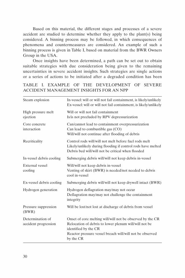
Based on this material, the different stages and processes of a severe accident are studied to determine whether they apply to the plant(s) being considered. A binning process may be followed, in which consequences of phenomena and countermeasures are considered. An example of such a binning process is given in Table I, based on material from the BWR OwnersGroup in the USA.
Once insights have been determined, a path can be set out to obtainsuitable strategies with due consideration being given to the remaininguncertainties in severe accident insights. Such strategies are single actions or a series of actions to be initiated after a degraded condition has been
30
TABLE I. EXAMPLE OF THE DEVELOPMENT OF SEVERE ACCIDENT MANAGEMENT INSIGHTS FOR AN NPP
Steam explosion In-vessel: will or will not fail containment, is likely/unlikelyEx-vessel: will or will not fail containment, is likely/unlikely
High pressure melt Will or will not fail containmentejection Is/is not precluded by RPV depressurization
Core concrete Can/cannot lead to containment overpressurizationinteraction Can lead to combustible gas (CO)
Will/will not continue after flooding of debris
Recriticality Control rods will/will not melt before fuel rods meltLikely/unlikely during flooding if control rods have meltedDebris bed will/will not be critical when flooded
In-vessel debris cooling Submerging debris will/will not keep debris in-vessel
External vessel Will/will not keep debris in-vesselcooling Venting of skirt (BWR) is needed/not needed to debris
cool in-vessel
Ex-vessel debris cooling Submerging debris will/will not keep drywell intact (BWR)
Hydrogen generation Hydrogen deflagration may/may not occurDeflagration may/may not challenge the containment integrity
Pressure suppression Will be lost/not lost at discharge of debris from vessel(BWR)
Determination of Onset of core melting will/will not be observed by the CRaccident progression Relocation of debris to lower plenum will/will not be
identified by the CRReactor pressure vessel breach will/will not be observedby the CR
identified. A degraded condition is often called a ‘plant damage state’, forwhich several approaches exist. Examples are given in Appendix I, where thedamage states refer to the core and the containment, or are directly linkedto certain parameters that exceed safety thresholds. Sometimes the initiatingevent and the degraded condition of the safety systems are also considered.A matrix of generic plant states has been developed by the OECD (seeSection 4 of Ref. [9]).
Some calculations may be needed to define a particular plant damagestate, as measured parameters may need interpretation. In order to avoid theneed for such calculations during an actual event, precalculated curves andgraphs may be used as CAs. Measuring the containment pressure and readingthe hydrogen concentration may, for example, give an immediate insight as towhether or not the containment is challenged. Appendix III contains furtherinformation and examples of such CAs.
Strategies are based on actions that are either still available to the operatoror are available only after certain systems have been restored to service.These arehigh level actions, as they are primarily meant to protect FP boundaries (contain-ment, SG tubes) and restore core/debris cooling to the extent possible. For thisreason, these actions are sometimes called CHLAs.A list of such CHLAs is givenin Appendix II. In general, they provide responses to the plant damage statesdefined above and are either initiated after recognition of such plant damagestates or after certain parameters exceed their safety thresholds, depending on theapproach chosen.7
As these actions may be executed under a variety of plant damage condi-tions, it is important to determine beforehand what their effect will be under theseconditions. Injecting non-borated water into a PWR vessel may, for example, haveprofoundly different effects when done on an intact core geometry than when thecontrol rods are already molten, or on a debris bed. Restart of a reactor coolantpump (RCP) may be very beneficial at the beginning of the accident while thereis still water in the RCS, but may greatly increase the risk of SG tube creep rup-ture if done later.
The Electric Power Research Institute (EPRI) has conducted a comprehen-sive study on the effect of CHLAs during plant damage states [6]. Note that thisinformation is usually not available from the plant PSA or IPE, as these normal-ly do not model the large variety of operator actions during and after the onset ofcore damage [9, 10].
31
7 The US Combustion Engineering Owners Group (CEOG) approach is anexample of the former and the Westinghouse Owners Group (WOG) approach anexample of the latter approach.

As pointed out in Section 2.5 and further explained and illustrated inAppendix II, actions should not be taken before their positive and negative con-sequences have been carefully considered. In this decision making process, theuncertainties inherent to severe accident phenomena also have to be taken intoaccount. The initiation and execution of actions, with all their side effects, is setforth in the SAMGs. Where quantitative information is needed or useful, use ismade of CAs, for example, if it is known beforehand how much water will be need-ed to remove the debris decay heat as a function of time after shutdown.Appendix III gives examples of such CAs.
As the independent development of suitable SAMGs is a major undertak-ing, it may be beneficial to use one of the generic approaches available.These havebeen developed by the industry, mainly by owners’ groups or larger utilities.8 Thegeneric material must then be adapted to meet the needs of individual plants.
4.1.2. Development of severe accident management strategies
The first step in the development of an AMP is to decide on and document the basic severe accident management strategies to be applied to thespecific plant. The strategies selected and their implementation may depend on the basic approach chosen based on national requirements. If plant modifi-cations are carried out to enhance the AMP, the degree of confidence in successful accident management actions will be increased.
If the AMP is developed from a generic programme based on the refer-ence plant concept, the development team should check that the differencesbetween the actual plant and the reference plant are not important enough to invalidate the strategies. It may be crucial to the preventive strategies thatthe reactors, as well as primary and relevant secondary system designs, are similar. The containment designs should also be similar. If this is not the case,the generic actions may still be valid, but they may need to be executed in a different order or initiated from other values of set points.9
When developing individual severe accident management strategies,interaction between various strategies may take place. Examples are interac-tion among primary circuit depressurization, hydrogen management, cavity
32
8 These include: in the USA,Westinghouse,ABB/Combustion Enginering, Babcock& Wilcox and General Electric; in France, Electricité de France; in Sweden, Vattenfall.
9 An example is the value of the core exit temperature for entering the WOGSAMG domain at WWER reactors, which is about 100°C lower than for Western PWRs.Another example is the sequence of primary and secondary feed and bleed actions atWWER reactors.
flooding, filtered venting and long term heat removal from the containment.These strategies should therefore not be developed independently. For someplant designs, even slight differences may have a major impact on the interac-tion of selected strategies.The resulting strategy basis document will be appliedfor the development of accident management procedures and guidelines.Thereare various ways to develop the accident management guidance based on theselected strategies (see Fig. 1):
(a) Incorporate preventive strategies into the EOPs and develop separateguidelines for mitigatory strategies,
(b) Include all accident management guidance (i.e. actions related to beyonddesign basis events) in separate procedures and/or guidelines,
(c) Incorporate accident management guidance as an enveloping symptombased or state oriented part of EOPs.
The following sections describe the process of developing the proceduresand guidelines.
4.2. DEVELOPMENT OF ACCIDENT MANAGEMENT PROCEDURES AND GUIDELINES
4.2.1. Development and writing
Development and writing of accident management guidance involves various closely related activities, each influencing the quality of the final prod-uct. There are quality assurance (QA) related requirements such as severalindependent reviews of each EOP by development team members as well as CR staff. There may be a need to assess modifications to strategies or devel-opment of new strategies which may influence already written procedures.Clarity of language, consistency of terminology and other style related require-ments should also be given proper consideration. Therefore, careful planning of the project with enough control points and effective interface between theindividual phases is important.
A critical part of development is feasibility assessment. This may be donewhile strategies are being developed and the guidelines are being written andincludes, but may not be limited to, evaluation of:
(a) The availability of information and instrumentation,(b) Equipment performance under severe accident conditions,(c) Accessibility of equipment,
33
(d) The necessity/possibility of overriding safety related instrumentation andcontrol (I&C).
For each severe accident management strategy, the existing instrumenta-tion should be analysed to check whether information necessary to monitorsafety functions, entry criteria to the relevant guideline, execution of the guideline and success criteria for the guideline are available. Anotherimportant aspect is the reliability and accuracy of the information in view ofenvironmental conditions of instrumentation and sensors. Procedures shouldinclude diversity and redundancy of measurement of some parameters andprovide alternative information sources for instruments that may have failed.
A prerequisite to execution of SAMGs is that equipment and instru-mentation used in any of these guidelines and strategies will perform asintended under the expected environmental conditions. It should be decidedwhether the proposed strategy should be implemented if this performancehas not been confirmed. If it is decided to implement the strategy even if suc-cess cannot be guaranteed, a minimum requirement would be that the infor-mation used to initiate and monitor execution and success of the strategy issufficiently reliable and the fact that equipment performance has not beenverified is known to the operator.
One of the major differences between procedures and SAMGs is theincreased need for on-site actions in different plant compartments, e.g. restora-tion of power to active components, repair of malfunctioning driving devices orcomponents, and operation of valves which are not power driven. When suchon-site actions are included in the guidelines, a careful examination should beconducted to determine whether the equipment concerned can be accessedwithout exposing personnel to excessive radiation, temperature and otherpotential dangers. Such an examination could also result in backfittingmeasures to reduce hazards and improve physical accessibility.
Since SAMGs are often based on the non-conventional use of existingoperating or safety systems, it is possible that the proposed staff interventionwill be prevented by the safety related I&C which has priority, or individualcomponent protection I&C. The operator must be able to deactivate thesefunctions without major delays when it is sufficiently clear that they wouldprevent him or her from executing the required accident management guideline.An important aspect of accident management planning is to ensure thatadequate administrative controls are in place to prevent premature or inappro-priate execution.
Depending upon the approach adopted, the following guidelines anddocuments need to be provided in parallel with the development and writing ofthe SAMGs:
34

(i) Guidance for the main CR operators during a severe accident.(ii) Guidance for the TSC (or equivalent support staff), including the chosen
methodology for recording implemented strategies and listing andaddressing long term concerns.
(iii) Computational aids to allow support staff to understand plant conditionsbased on the available instrumentation (not necessarily computerized) andto guide them in the selection and execution of suitable strategies; severalexamples of CAs and their application are given in Appendix III.
(iv) Calculation of the plant specific set points required by the SAMGs.
If the generic procedures and guidelines are written in another language,suitable provisions must be made to prevent confusion arising from language differences.
Based on the severe accident management strategies, procedures are tobe as user friendly as possible. Extensive use of flow charts, figures, tables anddiagrams should therefore be considered.
4.2.2. Preparation of background material and documentation
Background material is prepared in parallel with the development andwriting of the individual procedures as it has to document all the changes,improvements and modifications to generic strategies and procedural stepswhich were agreed to at the time of writing of the accident managementguidance. All grounds and justifications should be recorded to allow forfuture reviews and for the updating of procedures and guidelines in the lightof new knowledge of plant behaviour or modification of plant systems.
Because of the greater complexity of severe accidents compared withDBAs, as well as the continuously increasing knowledge base on plantbehaviour under severe accident conditions, consideration should be givento creating background documents in a way that allows easy upgrades andextensions and allows their use as reference and training materials.Background material should include:
(a) The technical basis for strategies,(b) Detailed description of instrumentation needs,(c) Results of supporting analyses,(d) The basis and detailed descriptions of procedure and guideline steps,(e) Set point calculations and their basis.
The preparation of good background documentation is very important.It has three primary functions:
35
(1) It is a self-contained source of reference,(2) It demonstrates compliance with the relevant QA requirements,(3) It provides support material to be used in training courses for technical
support staff and operators.
The reference and training course support functions of a background document may require it to be supplemented by additional analyses for illus-tration, even though generic preventive and mitigatory strategies have beenapplied and the assessment did not require a plant specific analysis.
Additionally, a ‘deviation document’ may be prepared which lists the differences between the plant specific procedures and guidelines developedand the generic ones, and explains the reasons for the differences.
4.3. SUPPORTING ACCIDENT ANALYSIS FOR DEVELOPMENT OFPROCEDURES AND GUIDELINES
Plant specific analysis requirements are discussed in terms of threecategories: preliminary analysis, development analysis, and analysis to supportverification and validation of procedures and guidelines. This section discussesdevelopment analysis and assumes that preventive actions are incorporatedinto the EOPs and guidance on mitigatory actions is given by the SAMGs.
4.3.1. Development analysis of EOPs
Development analyses are needed for detailed confirmation of thechoice of recovery strategies adopted, to provide necessary input to set pointcalculations (where appropriate), and to resolve other open items identifiedduring the writing of EOPs and the review of draft documents. Phase I of theAMP results in a preliminary list of such analyses. This list will include mostof the plant specific analyses needed for the development of EOPs because,provided the information inputs to phase 1 were sufficiently detailed and agood knowledge of design differences between the reference plant and theplant concerned is available, major changes to strategies or additional openitems should not arise during phase 2 (the actual developing and writing ofprocedures). In the case of more substantial design differences, such asthose between a PWR (reference plant) and a WWER, several behaviourdifferences related to plant design can be expected, which will have an effecton generic strategies.
Empirically, four types of open items are identified for this genericapproach:
36
(1) A need for evaluation, usually in terms of a specific system design orcapability to perform a certain function (for example, can the auxiliaryspray be used during a steam generator tube rupture (SGTR) to depres-surize the primary system without adverse thermal fatigue problems tocomponents);
(2) A need for an analysis to be performed (for example, what criterionshould be used to initiate primary side feed and bleed cooling);
(3) A possible need for a plant modification (for example, an increase in therange of core exit temperature measurements to allow monitoring of thecore cooling safety function);
(4) A need to change the staffing of the plant.
The list of open items defined in this way will therefore include the analysis required to resolve all issues before the detailed procedures are written. Such analysis should ideally be performed before phase 2 is begun, butcould in practice be performed in parallel with the writing of the phase 2procedures. The need for specific analyses will arise from attempts to refine thestrategies. Therefore easy availability of computing facilities, preferably withaccess to a full scope simulator, is very useful.
4.3.2. Analysis for the development of severe accident management guidelines
As in the EOP process, during phase 1 a list of issues or open items whichshould be resolved prior to or during the early stages in the preparation of plantspecific SAMGs will be identified. This list includes the analysis needed toconfirm the choice of recovery strategies adopted, to provide necessary input toset point calculations (where appropriate), and to resolve any other open itemsidentified during the development and review of SAMG strategies.These issuesor open items can be divided into the following four types:
(1) Evaluation of the capabilities and design of the systems. Based on theexperience gained in implementing SAMGs, the type of evaluationneeded most at this stage pertains to the performance of systems, and inparticular the capability of systems to perform functions other than thosefor which they were designed, together with assessment of the adequacyof the system to perform that function (for example, it may be possible toalign the containment spray system to inject directly into the reactorsystem; in this case it will be necessary to evaluate the flow rates achiev-able, system pressure ranges, ability to manually realign systems withinthe required time, and access to system components following a severe
37
accident, etc.). Additional evaluations for possible degradation of thedesigned systems need to be made before any changes to the physicalplant are considered. Increasing the failure probability for a systemdesign mode is not acceptable even if it offers an advantage during asevere accident condition because its use for design mode operation ismuch more likely than for a severe accident mode. Deviations from thisprinciple are acceptable only after careful consideration.
(2) Additional severe accident analyses to support individual severe accidentmanagement strategies and their interaction. For example, flooding thereactor cavity prior to vessel failure will enhance steam production andhence influence the time needed for venting the containment.
(3) Analysis needed to support development of CAs, diagnostic tools andguideline set points. For example, hydrogen combustion sensitivity calcu-lations and containment flooding analysis.
(4) Analysis needed to determine the ability of plant personnel to performthe tasks it may be required to perform as part of the accident manage-ment strategy under the conditions prevailing during an accident.
(5) Analysis needed to minimize the consequences of accident managementactions for the off-site population, including the consideration of provisionsto allow off-site officials to implement appropriate protective actions.
(6) A potential need for plant modification. The philosophy of SAMGs is toimplement guidance to make the best use of existing plant equipment inmitigating the consequences of a severe accident, and not to generateexaggerated requirements for system changes. However, in certain caseswhere changes would clearly bring great benefit, they may be recom-mended at this stage. For example, this approach may be applied mainlyto monitoring capability, such as hydrogen concentration measurementfor the containment and extension of the range of pressure instrumenta-tion for the containment.
4.4. DETERMINATION OF THE NEEDS FOR PLANT INSTRUMENTATION, EQUIPMENT AND MATERIAL,AND NECESSARY UPGRADES
Following the principles laid down in phase 1, detailed lists of the equip-ment and instrumentation needed and available and its capabilities must beprepared. Moreover, it needs to be demonstrated that the equipment foreseenin the strategies will meet the requirements.
With regard to the instrumentation, each requirement in the guidelines tomonitor a plant condition has to be taken into account. All possible means of
38

monitoring a particular parameter should be identified and prioritized. For pri-oritization, consideration should be given to:
(a) The information available regarding the expected environmental conditionsto be experienced by the instrument and its likely ability to withstand them,
(b) The qualification of the instrument,(c) The physical location of the instrument,(d) The ability of the instrument to perform the required function (its range,
accuracy and other capabilities).
Any limitations of the equipment and instrumentation identified need tobe specifically listed and included in the SAMGs. These limitations may giverise to requirements for upgrades or new dedicated instrumentation.
If analysis indicates that instruments are beyond their environmentalrange of accurate operation, it should be determined to what extent they canstill function. For instance, if a temperature indicator is not accurate in an envi-ronment of high humidity and radiation levels, it may not show the temperatureaccurately but may still have the ability to indicate whether the temperature isincreasing or decreasing.
Protection against radiation in the CR or the central location from whichaccident management will be co-ordinated and monitored (TSC, on-site emer-gency control centre), as well as important access routes to and from the plant,needs to be evaluated. Such protection would enable the long term presence ofoperating personnel in this location, but fulfilling the habitability requirementsmay necessitate plant upgrades.
4.5. INTEGRATION OF PROCEDURES, GUIDELINES AND THE PLANT’S EMERGENCY ARRANGEMENTS
As stated in Section 3.3.4, a transition from EOPs to SAMGs must bedefined. This can be either a fixed and irreversible transition or a parallelexecution of both, with a consistency check and priority given to the SAMGs.In the former case EOPs should be formally exited and need to be modified toinclude such exit conditions.
Paragraph 4.7 of Ref. [7] requires that the transition from normal operationto emergency operation be clearly defined and be effectively made withoutjeopardizing safety. It is required to designate the responsibilities of all thosepersons who would be present on the site in an emergency as part of the transi-tion. It is also required to ensure that the transition to emergency response andthe performance of initial response actions do not impair the ability of the
39

operational staff (such as the CR staff) to follow the procedures necessary forsafe operations and for taking mitigatory actions.
In addition, the process for the classification of emergencies and theactivation of the response, as established in Ref. [7] (paras 4.20, 4.70), should beintegrated into the process of activation of and transition to the accidentmanagement arrangements.
The actual transition is decided upon either by the CR staff when theyreach the exit conditions, or by higher levels in the emergency response organi-zation (ERO) hierarchy once they have taken note of the deteriorating situationof the plant. Appendix VII gives examples of the ‘exit criteria’ and transitionmechanisms for several actual applications.
As a consequence, the ERO should be reorganized to include the activitiesof the TSC (or equivalent support) with respect to SAMGs. This sometimesentails the establishment of a separate accident analysis team (AAT) whose primeresponsibility is to assess the plant state and give recommendations to the respon-sible management. Principles for dealing with these will have been defined inphase 1, and they must now be implemented. Important issues to be addressedinclude:
(a) Consistency with the emergency plan and any necessary upgrades to it,(b) Definition and approval of the responsibility matrix,(c) Definition of criteria for activation of the TSC and AAT,(d) TSC equipment for monitoring the current plant status.
The accident management guidance provides a function which has up tonow been missing at most plants — that of identifying, evaluating and imple-menting a set of well-defined recovery actions to terminate or mitigate releasesand restore a controlled stable condition in a plant which is experiencing a severeaccident. Since this function did not previously exist in any formal way, it has notbeen reflected in the organization defined by the plant’s emergency plan, whichin most cases deals primarily with the management of off-site occurrences. TheSAMGs must be integrated into the organizational structure defined in the emergency plan and interface with it to ensure a consistent and co-ordinatedresponse to severe accident conditions. Therefore, as part of the plant specificSAMG implementation, the emergency plan needs to be reviewed with respectto the actions that should be taken following the SAMG, to ensure that conflictsdo not exist. This review might recommend changes to the emergency plan toeliminate such conflicts.
It needs to be ensured that there are no conflicts with the arrangementsmade for security, fire fighting and support from off the site, such as the off-sitefire brigade or off-site security.
40
An important part of the integration of the SAMGs with the emergencyarrangements is the definition of the matrix of responsibilities for severe acci-dent mitigation actions. Use of the SAMGs will result in recommendations forCR operators to take specific actions in response to decisions made at theappropriate level. If the event has developed to the extent that SAMGs arerequired at all, which means that there has been a multitude of systems andequipment failures, the availability of equipment needed to perform mitiga-tory actions needs to be assessed ‘on the spot’, and continually reassessed duringthe use of the SAMGs. The guidelines therefore provide a structure for theevaluation of current plant conditions and equipment availability, and a meansto determine which of the available courses of action is the most appropriate.Following the evaluation and recommendation of a course of action, the decisionmust be made to either implement the proposed actions or choose alternativeactions, and then act upon that decision. Therefore, in a severe accident situa-tion, the on-site ERO must have three kinds of personnel:
(1) Evaluators: This is a team responsible for evaluating (using the SAMGs)and identifying a relevant accident management strategy. This requires adetailed knowledge of the SAMGs and a good understanding of theunderlying severe accident phenomena, as well as access to plant statusinformation. Sometimes this group of people is called the AAT or acci-dent management team (AMT).
(2) Decision makers: These persons have the authority to decide on theimplementation of an accident management strategy (as put forth by theevaluators) and have a broader understanding of the status of otheraspects of the emergency response, including effects off-site, which he orshe takes into consideration when making decisions.
(3) Implementers: This team implements the recommended strategy in theCR.
The above responsibilities are to be defined clearly in the AMP documentation. The emergency plan must reflect these responsibilities since itdefines the overall emergency organization.
The guidelines can be structured to separate the evaluators from theimplementers. Normally it is suggested that the evaluators be in the TSC andthe implementers the CR duty shift.10 However, during the plant specificimplementation phase the accommodation of these different SAMG functions
41
10 For example, the generic US SAMG has been written on this basis.

within the plant’s emergency organization (as defined in the emergency plan)has to be addressed on a plant specific level.
Apart from the three core functions mentioned above, other supportfunctions are useful or required. For instance, the flow of information betweenthe TSC (or equivalent group) and the CR, as well as from the TSC (or equiv-alent) to other parts of the ERO, must be well organized. These functions arebest assigned to dedicated ‘communicators’. However, as a severe accident willgenerate extensive communication needs, both on-site and off-site, it is desirable that the off-site needs do not interfere with accident management.Section 5 further describes the plant’s emergency organization, including theresponsibilities of the TSC and AAT.
Reference [7] establishes requirements for performing various emer-gency response functions, including: establishing emergency management oper-ations; identifying, notifying and activating; taking mandatory action; and pro-tecting emergency workers. These requirements form the foundation of theemergency response arrangements on the site.
4.6. VERIFICATION AND VALIDATION OF PROCEDURES ANDGUIDELINES
4.6.1. Verification
Verification is the evaluation which confirms the correctness of a writtenprocedure or guideline and ensures that technical and human factors have beenproperly incorporated. As such, the review of plant specific guidelines duringthe development phase, in accordance with QA regulations, forms part of theverification process. It is advisable to perform all implementation activities,including independent review, in accordance with internationally accepted QAguidelines as outlined in Refs [11, 12]. In addition, an independent review andverification by an independent organization which is completely familiar withthe AMP (for example, another similar plant) is recommended. Review by thenational regulatory body may also be required, though the extent of this reviewdepends on the individual organization’s or national requirements.
4.6.2. Validation
Validation is the evaluation which determines that the actions specified inthe procedures and guidelines can be followed by trained staff to manageemergency events. Emergency operating procedures can be validated in a num-ber of ways. The best is probably to use a full scope simulator facility. However,
42
engineering simulators, plant analyser tools, table top exercises, etc., might alsobe used. The amount of analysis needed beforehand depends on this choice.Validation also provides a ‘check’ on strategy selection and development andwill further confirm that strategies adopted directly from the generic guidelineswith no analysis at the phase 1 stage are appropriate.
Validation of SAMGs can be approached in various ways. Although thepurpose is the same as for EOP validation, different means will be adopted forvarious reasons. To date, SAMGs have been successfully validated using tabletop methods for the TSC staff and full scope simulators to exercise the opera-tor controlled transitions from the EOP [13–17]. Both individual exercises(involving the TSC, the operators or any other part of the plant emergencyresponse team separately) and integrated exercises (involving whole teams)have been performed. In setting up a validation programme for plant specificsevere accident management guidance a number of factors must be considered,including:
(a) The general approach: tabletop exercises, use of simulators or plant analy-sers, integrated versus limited/individual exercises.11
(b) The supporting analysis needs: the methods used to provide them, codesto be used, possible use of scenario templates, etc.
(c) The staffing of the validation team: speficially the exercise controllers andtechnical advisers who are not involved in the exercise but are responsi-ble for running and co-ordinating it. They must be able to define credibleplant conditions for the exercise on the spot.
4.6.3. Supporting analysis
The need for supporting analysis for verification and validation of EOPswill largely depend on the validation method. Therefore general guidancecannot be given. However, the following considerations apply:
(a) Verification of the plant specific EOP (i.e. evaluation to confirm thewritten correctness of the EOP and to ensure that technical and humanfactors have been properly incorporated) can normally be achievedwithout additional analysis.
(b) Validation (the real time evaluation performed to determine whether theactions specified in the EOP can be followed by trained operators tomanage emergency situations) is achievable in a number of ways.
43
11 In a limited exercise only the TSC staff are trained, not the integration of theentire emergency preparedness staff.

Probably the best method is use of a full scope simulator, but otherapproaches such as engineering simulators, plant analyser tools, tabletopexercises, etc., may also be used. The amount of analysis needed before-hand depends on which method is chosen.
(c) Validation provides a ‘check’ on strategy selection and further confirmsthat strategies that were adopted directly from generic guidelines with noanalysis during phase 1 are appropriate.
(d) Analysis to support verification and validation of guidelines may be donein order to demonstrate the capabilities and choice of appropriate strate-gies and optimize them. Such analysis should be done with a suitable andreasonably validated code, and should be carried out on a best estimatebasis [18]. The need for this type of analysis will also depend on the typeand methodology of the validation process.
(e) At present, most simulators are not capable of modelling system responsein a severe accident regime. A SAMG validation programme will insteadmost likely consist of a combination of simulator (for testing theEOP–SAMG transitions and the early phase of the accident) and table topexercises (to test TSC usage and long term recovery). Tabletop exerciseswill require some severe accident analysis prior to validation to serve as abasis for simulated plant response. The amount and scope of such analysismust be defined once the detailed approach to validation is finalized.
4.7. SPECIFICATION OF TRAINING NEEDS
During the AMP development phase training needs must be identified intime to allow preparation of the training programme which must be held duringthe implementation phase. The training plan identifies the staff members whoneed training, the level and scope of the training and its form for various groups.
Classroom courses can be used for basic familiarization with the accidentmanagement guidance. Drills and exercises, possibly using simulators withsevere accident modelling capabilities where these exist, are efficient trainingmethods. Implementation of training programmes will be discussed in moredetail in Section 5.
4.8. REVIEW OF THE AMP
Regular meetings are to be organized between the core team developingthe accident management guidance and the plant personnel who will berequired to use it. Information exchange between both groups can contribute
44

greatly to further development work at a later stage. Recommendations madeat these meetings can easily be included in the draft procedures and guidelinesbefore finalization.
Review meetings need to confirm that existing QA rules are beingobeyed, including that any requirements set forth by the regulatory body dur-ing the first phase of the project have been taken into account. This phase ofthe project is important because a careful review process can greatly enhancethe quality of the work. It can also minimize the time and work needed forcompletion of the project and implementation of procedures and guidelines.Appendix VI can be used as an example of such a review.
4.9. INVOLVEMENT OF THE REGULATORY BODY
The degree of involvement of the regulatory body varies from State toState. It will always be necessary to understand and check compliance with anyrequirements.
5. IMPLEMENTATION
5.1. OVERVIEW OF THE PLANT’S EMERGENCY ORGANIZATION
5.1.1. General
Reference [7] establishes specific requirements relating to the infrastruc-ture necessary for implementing and maintaining an emergency responsecapability. These infrastructural requirements cover: authority; organization;co-ordination of the response; plans and procedures; logistical support andfacilities; training, drills and exercises; and quality assurance programmes.These requirements form the basis for the implementation of the emergencyresponse arrangements necessary for accident management. The following textdeals with specific issues relating to on-site accident management.
An overview of a typical on-site organization for responding to an emer-gency is provided here, as the new SAMG functions interface with the existingemergency organization. The emphasis is on those people who are responsiblefor actually using the EOPs and SAMGs. There are variations between plantsand in the details, as each plant’s organization is different. The organizationdescribed here is typical of many US and Western European NPPs and can be
45
used as an example of the structure of a specific plant organization. It should benoted that TSCs may not currently be in place for all nuclear utilities. However,technical support should be accessible during an emergency. In the following theabbreviation TSC will be used to describe all such organized support.
5.1.2. On-site emergency organization
The plant’s on-site emergency organization and the duties and responsi-bilities of its members should be defined in the site specific emergency planand, where appropriate, supported by relevant procedures. The on-siteresponse to an emergency situation will depend on the following key staff:
(a) Paragraph 4.23 of Ref. [7] requires that there be a person on the site at alltimes with the authority and responsibility to classify a nuclear or radio-logical emergency and upon classification promptly, without consultation,initiate an appropriate on-site response.
(b) Operations staff: The operating shift is ultimately responsible for imple-menting recovery strategies. Organizations vary, but the operating shiftfor a single unit will normally consist of a shift supervisor and two or threeoperators in the CR, sometimes with an additional shift member out onthe plant. The shift staff are supervised by a shift manager. Normally, theshift manager may be responsible for more than one operating shift inmultiple unit plants. The shift manager reports to the head of the plant’soperations department, who himself reports to the plant manager.
(c) On-site technical support, usually located in a TSC: Before the advent ofaccident management, the on-site duties of the TSC were to provide, on anas-needed basis during an emergency, technical advice to the operation staff.The EOPs recognize that most plants have a TSC, and in the relatively fewcases in which EOPs require an evaluation of plant conditions before a possible action can be chosen, the EOP directs the operators to seek theTSC’s advice. However, in the past the role of the TSC has often been some-what unclear or ill defined. In spite of this, a TSC is part of the emergencyorganizations of most plants (it is a requirement in many countries), withfixed requirements as to the qualifications of its members, the provision ofa location equipped with data acquisition and display systems, plant statusboards and communications links with the main CR. The TSC’s role has,however, always been more oriented towards the support of operations andon-site plant recovery. Implementation of the SAMGs gives the TSCimportant new responsibilities. It would, in the event of a severe accident,now play a primary role. Technical support centre staffing varies, butnormally consists of a team of plant technical staff from different depart-
46
ments and with different areas of technical expertise. It is important thatthe activation of the TSC, including the members who are on call, and thetime allowed for the establishment of a functioning team once the CRrequests support, be considered for the successful integration of theSAMGs. The TSC normally consists of ten to twenty persons. This numbermay vary, depending on the evolution of the event and the technicalexpertise needed. In addition to the TSC, different technical departmentsare represented (e.g. operations, electrical engineering, systemsengieering). A secretary and a team member dedicated to updating plantstatus boards may be included. Actual repair and maintenance work iscarried out by a group of technicians assigned to those tasks which issometimes called the operations support centre (OSC).
(d) Accident assessment team (AAT)12: Most plants do not yet have an AAT.With implementation of SAMGs, a small team is required to actually usethe guidelines and develop the recommended recovery strategies. Thisteam is part of the TSC but retains a separate identity because it needsspecific training. The AAT would normally consist of three to four TSCmembers reporting to the TSC leader (not himself an AAT member). Itcomprises the evaluators described in Section 4.5 plus their support staffwho provide data on trends and communicate with the CR and the emergency response team.
(e) Emergency response team (ERT): The ERT is responsible for assessingthe off-site consequences of an event and recommending off-site actions.The functions of the ERT are defined in the emergency plan.They includecommunication with local authorities, declaration of the emergency statusof the plant, assessment of radioactive releases and prediction of likelyradiological consequences as the event evolves. The team leader, usuallycalled the emergency director or emergency controller, is specially trainedfor these duties, and will often be the plant manager or one of hisdeputies, or the manager of one of the other plant departments (such asoperations). The emergency director will perhaps have the best overallview of the event’s evolution. Usually, one of the tasks of the TSC is tosupply the ERT with FP source term projections for use in predictingpossible off-site exposure, or the ERT might do everything itself. A typical TSC organization is depicted in Annex III.13 Extensive guidelineshave been developed for some applications.14 These are intended tostructure and guide the work of the TSC.
47
12 This group is sometimes referred to as the AMT.13 This is an example from a typical BWR in the USA.14 Notably with the US BWR Owners Group (BWROG).
5.1.3. Organizational aspects of implementation
Organizational aspects of EOP implementation are quite limited sincethey primarily involve the operations department, with support from otherdepartments as needed. However, SAMG implementation has more organiza-tional implications which should be given initial consideration at this stage.These include:
(1) Definition of the lines of responsibility for the actions contained in theSAMGs, especially with regard to who is responsible for the evaluation,decision making and implementation of guidelines (see Section 4.5).
(2) Definition of the responsibility matrix must consider the organizationalaspects at the plant, the qualifications and expertise of the staff, and anylegal and licensing implications.
(3) The team charged with actually using the SAMGs, i.e. those responsiblefor evaluating plant conditions and recommending actions, should bedefined. Normally, this will be the AAT.
5.1.4. Involvement of the regulatory body
The development of an EOP/SAMG programme by the core team at theplant should involve a frequent dialogue with the regulatory body. The needfor this will vary from country to country, but in all cases it will be necessaryto understand the requirements (if any) and expectations of the regulator atan early stage and to develop an understanding of the likely approval process(if required) for the final EOP/SAMG package. It is therefore recommendedthat meetings be organized between the core team and representatives of theregulatory body at the end of each phase of the programme. It is also recom-mended that the severe accident sequences to be considered, the acceptancecriteria, and the analysis methodology be discussed with the regulatory bodyat an early stage in the preparation of the AMP.
5.2. TRAINING
5.2.1. General
All personnel and groups which are required to respond to an accidentshould be clearly identified and their training needs well defined.
48

5.2.2. Scope and means
Classroom training or exercises and drills can be used. In the latter, a severeaccident scenario is acted out by teams from the CR and the TSC.The focus is oncorrect execution of the EOPs in the pre-core damage state, the transition fromthe EOP domain to the SAMG domain, and the proper execution of the SAMGsapplying to the TSC (if any). Specific training is needed where responsibility ispassed on, e.g. from the CR to the TSC when an ‘exit’ condition is reached in theEOPs. Although the focus is on the correct execution of the severe accidentmanagement guidance by the CR personnel and the TSC, training on theoverall emergency plan should also be provided at regular intervals.
Training should be based on an appropriate ‘template’ consisting of a sce-nario plus all the ramifications needed to act out the scenario in a drill. Indeveloping this template it is important to include a wide spectrum of SAMGsso that the TSC and/or CR do not have only one or a small number of guide-lines to choose from. The template should be ‘dynamic’ in nature; as the vari-ous actions taken by the TSC and CR cannot be predicted in much detail, arange of possible responses should be considered. Time constraints will usuallyprevent the template from covering a complete core damage scenario, necessi-tating ‘jumps’ or ‘skips’ in the scenario. These interruptions should not receiveundue attention from the teams being trained since their working methodsshould reflect changes to parameters.
Drills have to include all team members. Too much emphasis on certainteam members (e.g. the decision maker(s)) should be avoided. Training will bemost realistic if the pre-core damage and transition phases are executed on aplant simulator.
The exercises and drills need to be observed by a team that assessesperformance. The teams involved should also give a self-assessment/critique oftheir performance. Assessments are documented and filed, and the lessonslearned are incorporated in the procedures and guidelines and in the trainingitself.
It should be emphasized that the success of the actions in terms ofcontrolling the simulated accident is, by itself, not the proper criterion tomeasure team performance. The drill/exercise is a success if the teams haveworked together, have followed their working procedures, and have estab-lished the proper level of communication, evaluation and decision making.
5.2.3. Skills of staff members
The following should be used as an aid to identify the individuals andgroups requiring training and the level of training needed:
49

(a) SAMG users: The members of the on-site emergency team who are given the task of actually using the SAMGs, evaluating plant status andrecommending the appropriate recovery strategy (see ‘Evaluators’ inSection 4.5) will require the most thorough training.
(b) Control room staff and supervisors: As discussed, most SAMG approach-es are organized in such a way that those responsible for evaluating theplant status and selecting the recommended recovery strategy will not bethe operators themselves, but a separate and perhaps remote (though stillon-site) team, most likely the TSC. Operators will still be responsible forimplementing the strategies recommended by this team (see‘Implementers’ in Section 4.5). It is therefore extremely important for theoperators to have confidence in the TSC and SAMGs and to understandthat actions may be required of them which appear to be in conflict withtheir established EOP training.The level of training provided must ensurethis without becoming an excessive burden on operating staff to the detri-ment of training in the use of EOPs.
(c) Emergency director/controller (see ‘Decision makers’ in Section 4.5): Theemergency director (or emergency controller) heads the on-site ERT. Heor she usually works at the plant management level and may be the plantmanager or the manager of operations. For SAMGs, this person is likelyto have the final say as to whether the TSC’s recommendations are to beimplemented by the CR. He or she must be completely familiar with theSAMGs and what they are based on. The personnel interfacing withSAMG users include:
— Emergency response staff: Those members of the ERT not directlyinvolved with SAMG implementation;
— Technical support staff not using SAMGs: Those members of the TSCnot directly involved with SAMG implementation;
— Off-site technical centre (if applicable): Members of off-site technicalsupport teams, often from the operating organization or the plant vendor;
— The regulatory body.
In practice, there is considerable overlap between the different functions.The training needs of the various members of the organization can beevaluated individually and personnel can, for example, be placed in one of thefollowing two groups:
(1) Staff needing detailed training in both the CR and TSC aspects of theSAMGs. This includes all operating shift staff and shift managers (includ-ing members of the TSC AAT), and all TSC leaders.
50

(2) Staff requiring an overview of the SAMG. This includes TSC memberswho are not part of the AATs, such as emergency controllers and othermembers of the emergency organization.
The level and content of classroom courses on severe accidents andaccident management needs, means and practices may differ for these groups.Plant specific training should also be tailored according to the chosenapproach to severe accident management and the function of the staff beingtrained, i.e. the training given to TSC members will differ from that given toemergency planners, etc. In some cases this training forms part of a formallicensing process (for example, EOP training of operators), in which caserecipients must comply with strict requirements for updating, refresher train-ing and testing. Plant specific training will normally be provided by operatingorganization or vendor staff.
Once the plant specific SAMGs are in place, the detailed training pro-gramme is implemented by the operating organization’s training department,the vendor, or both. Training must consider:
— The participants and their individual needs (TSC staff, emergencyplanners, engineering support staff, operators, etc.);
— The professional level of the participants;— Requalification/refresher needs;— Drills and exercises.
A technique known as the ‘systematic approach to training’ is being usedmore and more. This method adopts a structured approach which defines theobjectives, means and testing requirements of all aspects of the training inadvance [19].
Training must take place at regular intervals which are compatible withthe plant’s overall operator and technical staff training programme. It mustbe frequent enough to keep the responsible staff well informed andprepared.
5.3. STAFFING AND QUALIFICATION
The capabilities of the TSC (or that part of the emergency organizationresponsible for the SAMG) need to be reviewed to ensure appropriatestaffing and the qualifications of the staff to carry out their new SAMGduties [20].
51

5.4. REVISIONS TO THE AMP
It is important to upgrade the guidelines when new information which hasan impact on accident management becomes available from severe accidentresearch or from other sources. The operating organization is advised to active-ly follow such developments. The lessons learned from drills and exercises alsohave to be fed back into the programme.
52

Appendix I
PLANT DAMAGE STATES
The term ‘plant damage state’ is used to describe the degree of damage tothe reactor core, the RPV and the containment. Under the US severe accidentmanagement programme, EPRI developed a technical database for use by allUS owners groups (Babcox & Wilcox, Combustion Engineering ABB, GeneralElectric and Westinghouse) in the development of guidelines to combat theseconditions. At about the same time or a little later the PSA community used adescription of plant damage states for scenario development in level 2 PSAs orinterfaces between level 1 and level 2 PSAs.
Following are definitions of the EPRI technical database plant damagestates:
Damage states of the core and the RPV:
— OX:The core is overheated and significantly oxidized but retains its intactconfiguration;
— BD:The core is badly damaged and sufficient overheating has occurred init to melt and liquefy the reactor fuel and cladding;
— EX: The accident has progressed to failure of the RPV, and debris hasaccumulated in the containment.
Damage states of the containment:
— CC: Containment isolation is complete and containment heat removalsystems are available;
— CH: Containment isolation is complete but containment integrity is chal-lenged, either by loss of heat removal or hydrogen conditions which, if leftunchecked, could cause containment damage;
— I: The containment is impaired, i.e. the isolation function is not complete;— B: The containment is bypassed and may have no significant role in pre-
venting or mitigating a release to the environment.
When discussing SAMGs and their content, the plant damage states arereferred to as those plant damage conditions for which mitigatory strategiesshould be developed. Plant damage states can be presented as a matrix. In thefollowing sample matrix, used by the Combustion Engineering ABB reactors,the OX condition has been dropped since the EOPs can deal with this condi-tion if their configuration remains the same.
53
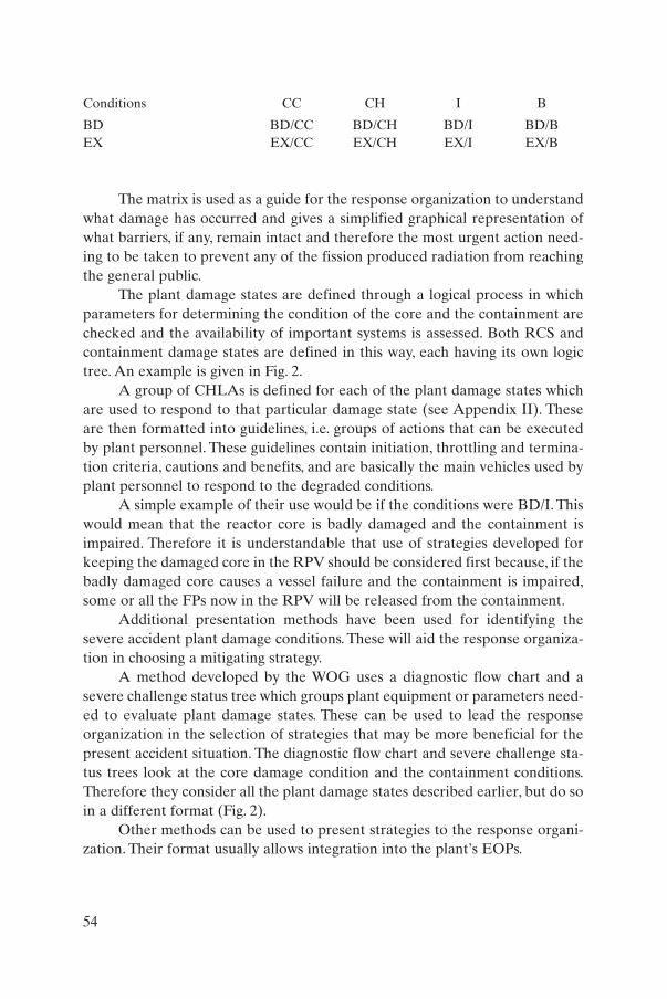
The matrix is used as a guide for the response organization to understandwhat damage has occurred and gives a simplified graphical representation ofwhat barriers, if any, remain intact and therefore the most urgent action need-ing to be taken to prevent any of the fission produced radiation from reachingthe general public.
The plant damage states are defined through a logical process in whichparameters for determining the condition of the core and the containment arechecked and the availability of important systems is assessed. Both RCS andcontainment damage states are defined in this way, each having its own logictree. An example is given in Fig. 2.
A group of CHLAs is defined for each of the plant damage states whichare used to respond to that particular damage state (see Appendix II). Theseare then formatted into guidelines, i.e. groups of actions that can be executedby plant personnel. These guidelines contain initiation, throttling and termina-tion criteria, cautions and benefits, and are basically the main vehicles used byplant personnel to respond to the degraded conditions.
A simple example of their use would be if the conditions were BD/I. Thiswould mean that the reactor core is badly damaged and the containment isimpaired. Therefore it is understandable that use of strategies developed forkeeping the damaged core in the RPV should be considered first because, if thebadly damaged core causes a vessel failure and the containment is impaired,some or all the FPs now in the RPV will be released from the containment.
Additional presentation methods have been used for identifying thesevere accident plant damage conditions. These will aid the response organiza-tion in choosing a mitigating strategy.
A method developed by the WOG uses a diagnostic flow chart and asevere challenge status tree which groups plant equipment or parameters need-ed to evaluate plant damage states. These can be used to lead the responseorganization in the selection of strategies that may be more beneficial for thepresent accident situation. The diagnostic flow chart and severe challenge sta-tus trees look at the core damage condition and the containment conditions.Therefore they consider all the plant damage states described earlier, but do soin a different format (Fig. 2).
Other methods can be used to present strategies to the response organi-zation. Their format usually allows integration into the plant’s EOPs.
54
Conditions CC CH I B
BD BD/CC BD/CH BD/I BD/BEX EX/CC EX/CH EX/I EX/B
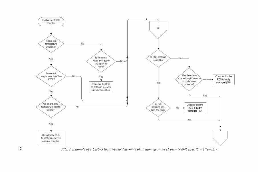
55
YesNo
No
No Yes
Yes
Yes
No
Consider the RCS to not be in a severe accident condition
Yes
No
No
A
No
Yes
Yes
Evaluation of RCScondition
Is core exittemperatureavailable?
Is core exittemperature less than
900°F?
Consider the RCS to not be in a severe accident condition
Are all anti-coremelt safety functions
fulfilled?
Is the vesselwater level above
the top of thecore?
Is RCS pressureavailable?
Is RCSpressure less
than 350 psig?
Consider that theRCS is badly
damaged (BD)
Has there beena recent, rapid increase
in containmentpressure?
Consider that theRCS is badly
damaged (BD).
FIG. 2. Example of a CEOG logic tree to determine plant damage states (1 psi = 6.8946 kPa, ˚C = 5–9 (˚F–32)).

The US BWROG has grouped its CHLAs into three guidelines whichrespond to deteriorating conditions in the vessel and the containment. The majorguideline is an integrated RPV and containment flooding guideline that definesresponses to the core degradation process in its increasing severity until vesselmelt-through, while keeping track of the degree of damage to the containmentwith emphasis on protection of the pressure suppression function. In Europeanapproaches the distinction between the different plant damage states is less explicit, but the countermeasures envisaged fulfil the same basic objectives.
56

Appendix II
CANDIDATE HIGH LEVEL ACTIONS
Appendix I provides a structure to define a limited number of plant dam-age states. The appropriate responses to these states are sometimes calledCHLAs (mainly in US approaches).
The following is a list of CHLAs, as used in various programmes:
(a) Inject into the RPV/RCS/RCP seal,(b) Depressurize the RPV,(c) Spray within the RPV (BWR),(d) Restart RCPs,(e) Depressurize the SGs (PWR),(f) Inject into (feed) the SGs,(g) Spray into the containment,(h) Inject into the containment,(i) Operate fan coolers,(j) Operate recombiners,(k) Operate igniters,(l) Inert the containment with non-condensables,15
(m) Vent the containment,(n) Spray the secondary containment,(o) Flood the secondary containment.
Additional considerations:
(p) External cooling of RPV,(q) Steam inerting of the containment.
The actual list depends on the plant’s characteristics and actual applica-tion will vary from plant to plant.
Normally both the positive and negative consequences of the CHLAsshould be considered.This should be done for each plant damage state to whichthe CHLAs are applied or for each of the guidelines that have been derivedfrom the CHLAs. Whether the CHLA/guideline is actually executed depends
57
15 This primarily applies to BWRs; it could also include dilution of PWR contain-ment with non-condensables with the aim of suppressing flame acceleration.

on the balance of these two. The following are examples of CHLAs and someof their positive and negative effects.
(1) Injection into the RCS
Positive effects:(a) A medium is provided to transfer heat away from the core.(b) It may help collapse the upper head steam void which enables better
RCS pressure control via the pressurizer.Negative effects:(a) A possible high pressure spike is generated when water is added to an
overheated core.(b) Hydrogen may be generated as a result of the zirconium–water reaction.(c) Injection of unborated water may lead to a return to criticality.(d) A steam explosion is possible if the injection rate is too fast.
(2) Injection into SGs
Positive effects:(a) Heat removal from the secondary side is provided, which could lower
the primary pressure and promote primary side water injection.(b) The tubes are protected from over temperature conditions and the
possibility of tube creep rupture is reduced.(c) Fission products are scrubbed if SG tube leakage has occurred.Negative effects:(a) Thermal shock from feeding a dry SG could cause the tubes to fracture.(b) Creep rupture of tubes could occur when a hot, dry SG is fed by lower-
ing the pressure on the secondary side of the tubes.
(3) Depressurization of the SGs
Positive effects:(a) Lower pressure water pumps can be used to feed the SG.(b) Heat is removed from the primary side of the SG.Negative effects:(a) Creep rupture of the SG is possible due to depressurization of the
secondary side of the SG and promotion of circulation on the primaryside of the tubes.
(b) If low pressure water pumps are sufficiently low in pressure, SG dryoutmay be necessary to reduce the pressure enough to allow feed.
58

(4) Restart of RCPs
Positive effects:(a) Any water volume in the crossunder pipe will be sent to the core, which
removes heat and offers some temporary retardation of core melt.(b) A recirculation path with the SG for reflux cooling could be established.Negative effects:(a) A recirculation pathway to the SG can be started and, if any SGs are dry,
tube creep potential is increased.
(5) Flooding of the reactor cavity
Positive effects:(a) Vessel failure can be prevented or delayed (to avoid creep rupture of the
vessel) if the water level inundates the vessel sufficiently.(b) A heat sink for the RPV is provided and reactor coolant boil-off is
reduced, provided the RPV insulation does not prevent the submergedvessel from steaming.
(c) The corium–concrete interaction is reduced if the RPV fails, even if thecavity is covered by only a small amount of water.
Negative effects:(a) If flooding is accomplished by containment spray, de-inerting the steam
atmosphere may cause a hydrogen burn.(b) Extended water injection into the containment could submerge safety
related equipment.(c) Extended injection of external water sources into the containment could
cause long term corrosion cracking concerns.(d) A steam explosion is possible.
(6) Depressurization of the RCS
Positive effects:(a) A low pressure water make-up system is allowed to supply water to the
RCS.(b) Stress in the primary system is reduced, thereby decreasing the
probability of creep rupture of SG tubes or reactor coolant systempiping.
(c) The effect of high pressure RPV failure is reduced, i.e. DCH concernsand corium relocation outside the RPV.
(d) A steam explosion or at least an energetic corium–water reaction ispossible.
59

Negative effects:(a) If pressure is reduced too soon the heat removal capability of the
coolant could be reduced.
(7) Spraying into the containment
Positive effects:
(a) The pressure and temperature in the containment is reduced, therebyreducing the challenge of containment failure and leakage.
(b) The airborne fission products are washed out, thereby reducing theirrelease through any containment leakage.
(c) Cavity flooding is promoted.Negative effects:(a) Containment of a steam atmosphere can be ‘de-inerted’, which can
increase the possibility of a hydrogen burn.
(8) Operation of containment fan coolers
Positive effects:(a) The pressure and temperature in the containment is reduced, thereby
reducing the challenge of containment failure and any leakage.Negative effects:(a) Containment of a steam atmosphere can be de-inerted, which can
increase the possibility of a hydrogen burn.
(9) Operation of hydrogen recombiners
Positive effects:(a) The hydrogen concentration in the containment atmosphere is reduced.Negative effects:(a) Some hydrogen recombiners may become ignition sources under high
hydrogen concentrations.
Reference [6] provides a complete description of both the positive and neg-ative effects of all CHLAs during all plant damage states. Some CHLAs werestudied further in the late 1990s and equipment was developed for some plantsto enhance their execution. For example, catalytic recombiners were developedthat are able to remove hydrogen without combustion. Also, filtered vents weredeveloped for a number of containments. Work is continuing to give furtherinsight into the mechanism of cooling the RPV from outside by flooding the cav-ity. Utilities may consider upgrading their existing programmes on the basis of thiswork and regulatory bodies may consider upgrading their national requirements.
60

Appendix III
COMPUTATIONAL AIDS
During BDBAs all the activities performed by the response organizationshould be evaluated for ease of application.The stress level of all personnel willbe high during such events. Therefore by reducing the potential for humanerror, ease of application will increase the overall success of the responseorganization. One of the possible ways of accomplishing this is to develop cal-culation methods that may be used by the implementers in combating plantdamage. Some of these could be developed before they are needed. ThereforeCAs could be developed for the response organization prior to an actual event.Such CAs are obtained using simplified assumptions and typically are present-ed graphically (with parameter graphs, diagrams, nomographs, tables, etc.).Several plants which have developed SAMPs have such CAs.These CAs are allplant specific but can be calculated by individual NPPs as part of the develop-ment process of their SAMPs. Some examples of CAs follow:
(a) The coolant injection rate needed for the removal of decay heat from thecore, plus heat from metal oxidation and accumulated heat of the RPVstructural material;
(b) Hydrogen production due to a steam metal oxidation reaction.
The following two examples are described in more detail:
(1) Containment water level and volume (Fig. 3): The purpose of this CA isto provide a correlation between the injected water volume and the con-tainment water level so that flooding levels in the containment can beevaluated. This allows the response organization to estimate when theRPV has been sufficiently flooded to be an effective external heat sinkwhich might possibly prevent an RPV failure. It also informs the responseorganization as to what equipment will be ineffective due to flooding.One NPP used multiple parameters to estimate the flood level of the con-tainment. Figure 3 shows this graphically for a Westinghouse plant. Thevertical axis is the containment water level and the horizontal axis is theinjected water volume. The line representing the increase in the contain-ment level also shows the level which represents a full volume of one ormore refuelling water storage tanks (RWSTs). This line also shows whichequipment would be submerged as the water level in the containmentincreases.
61
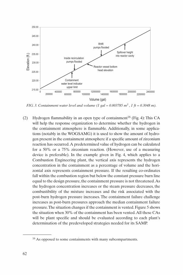
(2) Hydrogen flammability in an open type of containment16 (Fig. 4): This CAwill help the response organization to determine whether the hydrogen inthe containment atmosphere is flammable. Additionally, in some applica-tions (notably in the WOGSAMG) it is used to show the amount of hydro-gen present in the containment atmosphere if a specific amount of zirconiumreaction has occurred.A predetermined value of hydrogen can be calculatedfor a 50% or a 75% zirconium reaction. (However, use of a measuringdevice is preferable). In the example given in Fig. 4, which applies to aCombustion Engineering plant, the vertical axis represents the hydrogenconcentration in the containment as a percentage of volume and the hori-zontal axis represents containment pressure. If the resulting co-ordinatesfall within the combustion region but below the constant pressure burn lineequal to the design pressure, the containment pressure is not threatened.Asthe hydrogen concentration increases or the steam pressure decreases, thecombustibility of the mixture increases and the risk associated with thepost-burn hydrogen pressure increases. The containment failure challengeincreases as post-burn pressures approach the median containment failurepressure.The situation changes if the containment is vented. Figure 5 showsthe situation when 30% of the containment has been vented.All these CAswill be plant specific and should be evaluated according to each plant’sdetermination of the predeveloped strategies needed for its SAMP.
62
16 As opposed to some containments with many subcompartments.
250.00
245.00
240.00
235.00
230.00
225.00
220.00
215.002400000
22000002000000
180000012000000
600000400000
2000000 800000
1000000 14000001600000
Spillover height
into reactor cavity
➞
Containment
water level indicator
upper limit
➞
Inside recirculation
pumps flooded
➞
Reactor vessel bottom
head elevation
➞
➞
RHR
pumps flooded
Ele
vatio
n (f
t.)
Volume (gal)
FIG. 3. Containment water level and volume (1 gal = 0.003785 m3 , 1 ft = 0.3048 m).
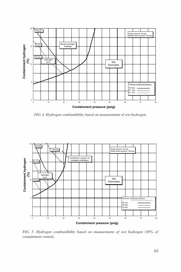
63
0
5
10
15
20
0 10 20 30 40 50 60 70 80
105 psig
85 psig
65 psig
Co
nta
inm
en
t h
yd
rog
en
(%)
Containment pressure (psig)
105 psig
85 psig
65 psig
Hydrogen
burn
Severe hydrogen
challenge
Not
flammable
Design pressure: 50 psig
Median failure pressure: 128 psig
Post-burn containment pressure
85 psig
65 psig
45 psig
>105 psig
85 psig
65 psig
45 psig
0
5
10
15
20
0 10 20 30 40 50 60 70 80
Co
nta
inm
en
t h
yd
rog
en
(%)
Containment pressure (psig)
Hydrogen
burnNot
Flammable
Design pressure: 50 psig
Median failure pressure: 128 psig
Post-burn containment pressure
Insufficient oxygen for
complete combustion
FIG. 4. Hydrogen combustibility based on measurement of wet hydrogen.
FIG. 5. Hydrogen combustibility based on measurement of wet hydrogen (30% of containment vented).

Appendix IV
TYPICAL PARAMETERS AND MECHANISMS USED FOR INITIATION OF PREVENTIVE AND MITIGATORY ACTIONS
The following general approach is proposed for the selection of instru-mentation and parameters needed to diagnose and monitor those conditionswhich cause the initiation of accident management strategies:
(a) The existing instrumentation of an NPP has to allow monitoring andcontrol of all the important parameters of any accident which does notexceed the NPP’s design basis envelope. Such control is necessary tokeep the event within the design basis envelope, possibly by means ofoperator intervention in accordance with existing EOPs.
(b) In the case of a BDBA, some parameters exceed design basis values.Some extension of existing instrumentation is necessary to enable theoperator to monitor the current status of the plant and evaluate itssafety margins. Because the operator is expected to take preventiveaccident management actions in compliance with symptom basedEOPs (both event oriented and the function oriented parts), instru-mentation showing all the parameters used as symptoms for startingpreventive actions or monitoring their efficiency in a BDBA environ-ment has to be provided or upgraded to survive adverse environmentalconditions.
(c) In severe accidents which may involve very harsh environmental con-ditions in the containment, reliable information on symptoms whichstart mitigatory measures is needed. This information is characterizedby various measurements of the containment and on-site parameters.
According to the above grouping, three classes of instrumentation can be introduced for the purpose of this report: the DBA group, the BDBA group (core damage prevention) and the severe accident group (mitigationof consequences). Examples of the instrumentation needed for diagnosis andmonitoring are given below:
Design basis accidents:
— Design instrumentation;
64
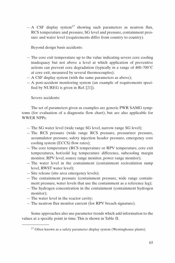
— A CSF display system17 showing such parameters as neutron flux,RCS temperature and pressure, SG level and pressure, containment pres-sure and water level (requirements differ from country to country).
Beyond design basis accidents:
— The core exit temperature up to the value indicating severe core coolinginadequacy but not above a level at which application of preventiveactions can prevent core degradation (typically in a range of 400–700°Cat core exit, measured by several thermocouples);
— A CSF display system (with the same parameters as above);— A post-accident monitoring system (an example of requirements speci-
fied by NUREG is given in Ref. [21]).
Severe accidents:
The set of parameters given as examples are generic PWR SAMG symp-toms (for evaluation of a diagnostic flow chart), but are also applicable forWWER NPPs:
— The SG water level (wide range SG level, narrow range SG level);— The RCS pressure (wide range RCS pressure, pressurizer pressure,
accumulator pressure, safety injection header pressure, emergency corecooling system (ECCS) flow rates);
— The core temperature (RCS temperature or RPV temperature, core exittemperatures, hot/cold leg temperature difference, subcooling marginmonitor, RPV level, source range monitor, power range monitor);
— The water level in the containment (containment recirculation sumplevel, RWST water level);
— Site release (site area emergency levels);— The containment pressure (containment pressure, wide range contain-
ment pressure, water levels that use the containment as a reference leg);— The hydrogen concentration in the containment (containment hydrogen
monitor);— The water level in the reactor cavity;— The neutron flux monitor current (for RPV breach signature).
Some approaches also use parameter trends which add information to thevalues at a specific point in time. This is shown in Table II.
65
17 Often known as a safety parameter display system (Westinghouse plants).
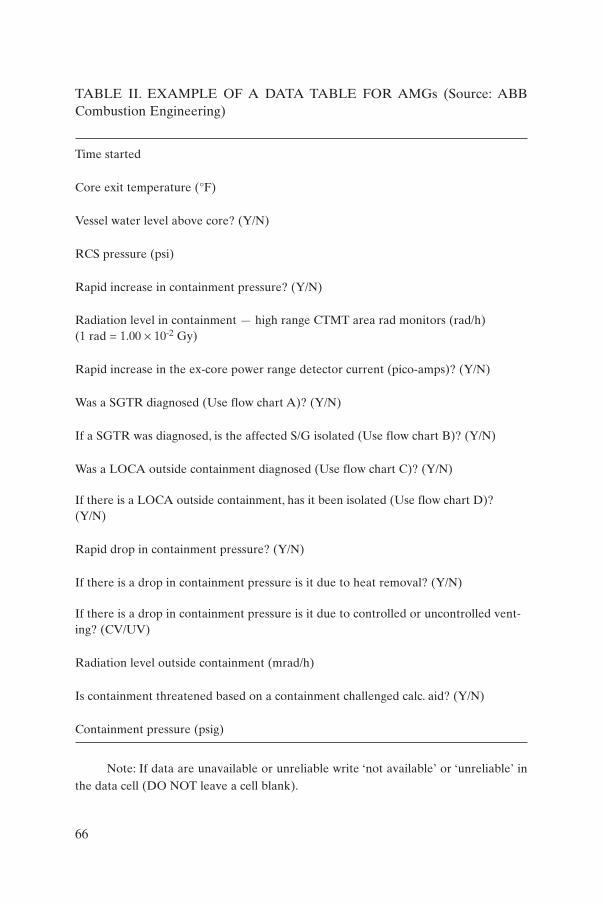
Note: If data are unavailable or unreliable write ‘not available’ or ‘unreliable’ inthe data cell (DO NOT leave a cell blank).
66
TABLE II. EXAMPLE OF A DATA TABLE FOR AMGs (Source: ABBCombustion Engineering)
Time started
Core exit temperature (°F)
Vessel water level above core? (Y/N)
RCS pressure (psi)
Rapid increase in containment pressure? (Y/N)
Radiation level in containment — high range CTMT area rad monitors (rad/h)(1 rad = 1.00 ¥ 10-2 Gy)
Rapid increase in the ex-core power range detector current (pico-amps)? (Y/N)
Was a SGTR diagnosed (Use flow chart A)? (Y/N)
If a SGTR was diagnosed, is the affected S/G isolated (Use flow chart B)? (Y/N)
Was a LOCA outside containment diagnosed (Use flow chart C)? (Y/N)
If there is a LOCA outside containment, has it been isolated (Use flow chart D)?(Y/N)
Rapid drop in containment pressure? (Y/N)
If there is a drop in containment pressure is it due to heat removal? (Y/N)
If there is a drop in containment pressure is it due to controlled or uncontrolled vent-ing? (CV/UV)
Radiation level outside containment (mrad/h)
Is containment threatened based on a containment challenged calc. aid? (Y/N)
Containment pressure (psig)
Appendix V
PREVENTIVE ACCIDENT MANAGEMENT ACTIONS
The objective of preventive accident management actions is to preventor terminate core degradation as early as possible. Prevention of reactorcore degradation should be the primary goal of any AMP. Preventive acci-dent management actions should be distinguished from mitigatory ones.
Generic strategies and approaches can be used as examples of preven-tive accident management strategies for WWER NPPs. An additional exam-ple of a possible preventive accident management action (secondary feedand bleed) used in Sweden has also been included.
The Westinghouse generic approach to preventive accident manage-ment uses six CSFs — subcriticality, core cooling, heat removal, RCS integri-ty, containment integrity and inventory — which are monitored on-line usingCSF status trees while the operators follow the event oriented (symptombased) part of the EOPs. When a CSF is severely challenged the operatorsswitch to function restoration guidelines, which are the function orientedpart of EOPs. Although all EOP actions or activities are meant in principleto prevent core damage, the term preventive accident management actionseems to be more appropriate for activities that are considered in the func-tion restoration guidelines, i.e. activities initiated by the operator to recoverfrom a severe challenge to core safety. These preventive accident manage-ment actions are sometimes referred to as recovery actions. In part, accidentmanagement preventive actions are based on a philosophy similar to that ofprevious activities (restoring cooling, restoring safety injection, restoringlevel, restoring concentration, decreasing cooling, attempting to utilize othersources of water, power, etc.); only the priority of the actions to be taken isadapted and less stringent safety limitations are applied.
Some preventive accident management actions from the start includeactions that are qualitatively different from previous activities. Good exam-ples are initiation of feed and bleed in loss of heat removal conditions, RCSand SG depressurization in loss of core cooling conditions. These specificpreventive accident management actions are discussed below with the aim ofproviding sufficient insight into their logic but not dealing with them indetail.
Plant specific EOPs were developed for several WWER-440/213 NPPsby adapting generic Westinghouse guidelines, as described in Sections 3 and4. Some of the generic preventive accident management measures and entrysymptoms were reassessed as part of PHARE project 4.2.7a/93, on BeyondDesign Basis Accident Analysis and Accident Management, sponsored by
67

the European Union from 1996 to 1998. As a main computational tool, theMAAP4/WWER code with a specific input file from the Bohunice NPP(Slovakia) was used. The results of the preventive accident managementmeasures are summarized below.
V.1. SUBCRITICALITY
Entry condition (symptom): The reactor is not shut down as a result ofneutron flux measurement.
Preventive accident management measures:
(a) Attempt to shut down the reactor by manually positioning the controlrods in all possible ways;
(b) If the actions taken in (a) are not successful, stop heat removal (includ-ing manual turbogenerator trip) and provide feedwater flow by meansof at least one auxiliary feedwater pump;
(c) Let the reactor stabilize power by means of moderator temperaturefeedback effects at the equilibrium with the feedwater RHR capabili-ty;
(d) Borate RCS using any available means.
A technical problem in the application of these preventive actions isthe shut-off head pressure of the pumps which are available for injectingboric acid into the RCS. Therefore depressurization of the RCS throughpressurizer relief valves (possibly an automatic action) may in some cases bea precondition for effective boric acid injection.
V.2. CORE COOLING
In the following only the highest priority challenge to CSF core coolingis considered. Less ‘drastic’ preventive actions (secondary depressurizationat a lower rate) will have been performed already before the onset of theinadequate core cooling condition.
Entry condition (symptom): 650°C at the core exit.The following preventive accident management measures are to be
applied sequentially:
(1) Attempt to restore safety injection;
68

(2) If (1) is not successful, depressurize the SGs as quickly as possible toallow injection of low pressure water sources into the RCS (hydroac-cumulators, low pressure ECCS pumps);
(3) If (2) is not successful, attempt to restart RCPs, even if damage to themis to be expected, to inject residual water trapped in lower parts of theRCS into the core and to restore cooling;
(4) If (3) is not successful, depressurize the RCS by any available means(through pressurizer relief and safety valves) to allow low pressuresources to be injected into the RCS.
V.3. HEAT REMOVAL
The basic preventive accident management action is primary feed andbleed.
Generic entry conditions (symptoms) for starting primary feed andbleed are:
– The minimum SG level allowing recovery of core cooling,– An RCS temperature allowing recovery of core cooling.
During the development of an EOP for WWER V-213 NPPs, the fol-lowing primary feed and bleed entry conditions were considered feasible:
– The minimum SG level effective for heat removal;– An RCS temperature of 320°C (corresponding to this minimum SG
level in conservative analysis of feedwater flow transients);– A feedwater flow less than the minimum necessary for a safe RHR
when the RCS temperature cannot be stabilized by the secondary side.
In the validation phase of the EOP the third entry condition was foundtoo difficult for the operators to evaluate and therefore the temperaturesymptom will probably be used in the future.
Preventive accident management measures:
– Attempt to restore feedwater flow to at least one SG by all availablemeans and minimize heat production in the RCS (tripping all RCPs);
– Establish primary feed and bleed by:(a)iStarting high pressure safety injection (HPSI) pump(s),(b)iManually opening pressurizer relief and/or safety valve(s),
69
(c)iCooling down RCS and transferring injection to low pressure safetyinjection (LPSI) pumps as soon as the RCS parameters allow(giving adequate consideration to maintaining RCS subcooling inall situations).
V.4. REMAINING CSFs
Three CSFs remain:
(1) Integrity of the RCS (safety of the RPV in relation to brittle fracture phenomena in subcooling transients);
(2) Integrity of the containment (challenge to the containment safety function from high pressure, low pressure, flooding and high radiationlevels);
(3) Inventory of the RCS water volume (abnormal pressurizer level).
In contrast to the first three CSFs, a violation of any of those listed aboveis not directly related to core damage (not taking into account catastrophicfailure of the RPV due to transients). Therefore they do not require drasticpreventive accident management measures. The actions taken in EOPs arebasically ‘parameter recovery’ or ‘parameter stabilization’ in nature.
V.5. STATION BLACKOUT
A station blackout is an event combining a loss of heat removal accident(loss of feedwater flow) with a potential LOCA (through pressurizersafety/relief valves and the RCP’s seals). Recovery from a blackout is compli-cated by the concurrent loss of non-vital instrumentation and controls andlater, when the batteries are depleted, even the loss of vital I&C. The only wayto prevent core damage is to restore the power supply to at least some of thesystems needed for decay heat removal which, in most situations, takes time.Therefore some of the preventive accident management measures concentrate on winning time to allow for restoration of power sources. SomePWRs have a secondary feed and bleed capability which is basically amitigatory system preventing vessel failure. Secondary feed and bleed, ifapplied early enough, can also be useful in the prevention of core damage.
Entry condition (symptom): Blackout of the station.
Preventive accident management measures:
70
(a) Actions aimed at delaying depletion of batteries.(b) Actions minimizing any loss of RCS coolant (such as seal leakage of
the RCP) or secondary side coolant (such as SG blowdown).(c) Secondary side depressurization aims at reducing the temperature and
pressure in the RCS to delay failure of the RCP seals and/or minimizeleakage when they fail due to overheating or overpressurization. Thedrawback of this preventive action is the loss of secondary water andthe jeopardizing of heat removal in a later phase. Therefore use of thispreventive measure requires the availability of a feedwater source(turbine driven feedwater pump). The presence of large volumes of sec-ondary water in horizontal SGs could also, in principle, justify use ofthis preventive action.
(d) Primary depressurization is not used in the generic Westinghouseguidelines because it accelerates uncovering of the core. After the corehas been partially uncovered, but before significant core damage canoccur, primary depressurization may be useful to allow the hydroaccu-mulators to inject and delay further damage. This action can also beconsidered to be a mitigatory accident management action because itprevents high pressure RPV failure.
In the EOPs for the WWER-440/213 NPP, secondary side depressur-ization alone was implemented after approximately two hours of powerrecovery activities, in view of limited knowledge of the specific behaviour ofthe plant under core damage conditions. Recent experiments devoted toassessment of the vulnerability of RCP seals have shown that long term survivalof the seal is possible if the temperature is maintained below ~250°C. Primaryside depressurization has not been implemented in V-213 plant specific EOPsdue to insufficient analytical knowledge at the time of their development.
Secondary feed and bleed consists of feeding one or two SGs with fireextinguishing water (other sources are also possible) and relieving steam bymeans of SG relief valves. A negative aspect of this strategy is the thermalstress on the SG tubes.
The PHARE 4.2.7a project analysed preventive accident managementactions applicable in conditions of inadequate core cooling, loss of heatremoval and station blackout in more detail. The main conclusions for inad-equate core cooling were:
(1) The condition for starting preventive actions (650°C) should bereassessed because the core is already considerably degraded at thistemperature and the rate of further degradation is too high. Based onanalytical data, a value of between 550 and 600°C is preferable.
71
(2) Restart of RCPs is effective for WWER reactors, similarly to PWRreactors, and core damage can be delayed for several hours (for exam-ple, more than 3 hours for a 10 mm LOCA).
(3) The effectiveness of secondary depressurization of V-213 plants has notbeen confirmed if the preventive action is started at a temperature of650°C. Secondary depressurization is better started at a temperaturebelow 600°C. However, this finding may be dependent on specificMAAP4/WWER modelling, and additional analyses with improvedmodelling of certain phenomena are suggested.
(4) Consideration should be given to reversing the priority of secondaryand primary depressurization if the MAAP4/WWER results are confirmed (see point (3)).
(5) Primary depressurization proved to be effective in all situationsanalysed.
(6) The availability of an LPSI system is necessary for long term preven-tion of core degradation.
The main conclusions for loss of heat removal were:
(a) If the entry condition for primary feed and bleed is the temperature, avalue considerably higher than 320°C is acceptable (up to the temper-ature used as a symptom of inadequate core cooling — currently650°C).
(b) The limitations on the time of initiation of primary feed and bleed,which are known for PWRs and which depend on parameters like reac-tor rated power, relief capacity and RCS volume, have not been provenfor WWER V-213 reactors.
(c) Use of secondary depressurization as a preventive accident manage-ment action to support primary feed and bleed under certain condi-tions was not found to be beneficial because:(i) If HPSI is not available, secondary depressurization does not bring
the RCS pressure below the shut-off head pressure of the LPSIpumps and therefore primary feed and bleed cannot be establishedwith LPSI pumps. This leads to earlier uncovering of the core.
(ii) If HPSI is available, secondary depressurization accelerates thedevelopment of the accident and the primary feed and bleed entryconditions are reached earlier. This leaves less time for attempts torestore the feedwater system.
The main conclusions for station blackout were:
72
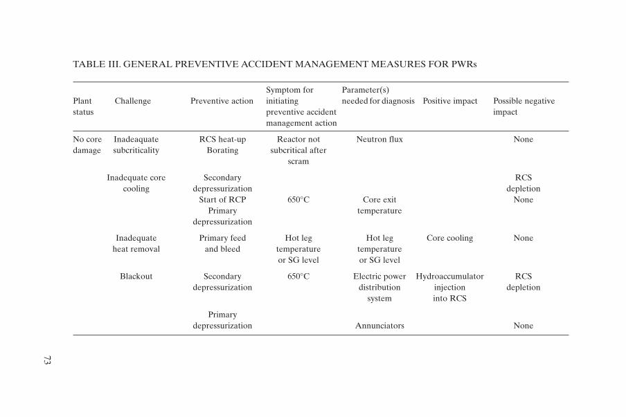
73
TABLE III. GENERAL PREVENTIVE ACCIDENT MANAGEMENT MEASURES FOR PWRs
Symptom for Parameter(s) Plant Challenge Preventive action initiating needed for diagnosis Positive impact Possible negativestatus preventive accident impact
management action
No core Inadeaquate RCS heat-up Reactor not Neutron flux Nonedamage subcriticality Borating subcritical after
scram
Inadequate core Secondary RCScooling depressurization depletion
Start of RCP 650°C Core exit NonePrimary temperature
depressurization
Inadequate Primary feed Hot leg Hot leg Core cooling Noneheat removal and bleed temperature temperature
or SG level or SG level
Blackout Secondary 650°C Electric power Hydroaccumulator RCSdepressurization distribution injection depletion
system into RCS
Primarydepressurization Annunciators None
(1) Secondary depressurization: If there is no leakage through RCP seals,depressurization accelerates uncovering of the core and core damage.
(2) Primary depressurization: Start of primary depressurization at 650°Chas a beneficial effect in all analysed cases because hydroaccumulatorsinject water into the RCS, delaying subsequent core degradation. Thepressure is also lower during core melt and vessel attack.
The analyses helped to find an optimum rate of relief flow at which thepositive effect of depressurization is optimally balanced with RCS inventoryloss. In the Bohunice NPP this flow corresponds to the combination of onepressurizer safety valve plus a relief valve. Table III summarizes general preventive accident management measures for PWRs.
74

Appendix VI
REVIEW OF AN AMP
VI.1. METHODOLOGY
At various stages in the development and implementation of an AMPand, in particular, prior to its implementation, the AMP should be reviewedfrom the point of view of its completeness and quality. Suggestions and goodpractices are given in this publication and in Refs [3, 9], which describe in detailthe basic components of and approaches used in the preparation, developmentand implementation of AMPs. The review can be carried out either by the NPPpersonnel or by an external review team, possibly an IAEA review team. Thisappendix describes one of the possible methodologies for reviewing whetheran AMP is sufficiently comprehensive and whether all relevant issues havebeen adequately addressed.
The methodology refers to an IAEA publication on Basic SafetyPrinciples for Nuclear Power Plants [1]. Safety principles are shared safety con-cepts indicating how to achieve safety objectives at different levels of defencein depth. As stated in Ref. [1], “The safety principles do not guarantee thatNPPs will be absolutely free of risk, but, when the principles are adequatelyimplemented, the plants should be very safe…”. The principles do not differ-entiate between new and existing plants, but do of course consider necessarydifferences in implementation.
The major part of level 4 of defence in depth, which covers the control ofsevere conditions, including prevention of accident progression and mitigationof the consequences of a severe accident, is included in the AMP. Reference [1]gives guidance on how to specify relevant safety principles for each level ofdefence in depth, including level 4. The principles for level 4 have been select-ed and grouped as follows:
Group 1: Strategies for accident management
(a) Strategy for accident management.
Group 2: Performance of equipment in accident management
(a) Equipment qualification,(b) Automatic shutdown systems,(c) Preservation of control capability,
75
(d) Station blackout,(e) Achievement of quality,(f) Verification of design and construction,(g) Pre-operational plant adjustment,(h) Engineered features for accident management,(i) Quality assurance in operation,(j) Maintenance, testing and inspections.
Group 3: Response of personnel in accident management
(a) Validation of operating and functional test procedures,(b) Training and procedures for accident management.
Group 4: Operational excellence and physical protection of the plant
(a) Operational excellence,(b) Physical protection of the plant.
Group 5: Interface with off-site emergency planning
(a) Emergency arrangements,(b) Assessment of accident consequences and radiological monitoring,(c) The radiological impact on the public and the local environment,(d) Off-site support.
Group 6: Emergency heat removal and ultimate heat sink provisions
(a) Emergency heat removal,(b) Ultimate heat sink provisions.
Group 7: Protection of the containment structure
(a) Protection of the containment structure.
Group 8: Confinement of radioactive material
(a) Confinement of radioactive material.
The safety principles show the complexity of the issue on the one handbut, on the other hand, allow for a comprehensive review of the AMP aimed atevaluating whether all aspects are being adequately considered.
76
Practical guidance for the review of an AMP can use an ‘objective tree’technique. This technique, as demonstrated in Fig. 6, is used to relate the objec-tives of each level of defence to the necessary provisions in design and opera-tion.The objectives of each level of defence clearly state what is to be achieved.The safety principles show how to achieve it and give an indication of whichrelevant safety functions should be maintained. Challenges causing the deteri-oration of each safety function can be specified, various mechanisms inducedby these challenges can be identified, and adequate provisions for preventionor control of these mechanisms can be made. The safety principles also indicatehow to select and evaluate the adequacy of individual provisions which need tobe implemented to prevent mechanisms which could prevent the safety functions from occurring. The provisions reflect measures applicable to allstructures, systems, components and procedures important to safety during allthe stages of design and operation of an NPP. Figure 7 shows the basic elementsof the technique for level 4 of defence in depth. This technique has been usedto construct full objective trees, including specification of provisions for each ofthe relevant safety principles. The entire set of objective trees for all safety principles can be used afterwards as a checklist (‘reminder’) for completeness(adequate consideration of all aspects) of the AMPs. References [1, 3, 9], as wellas the main part of this report, explain the contents of the provisions in objec-tive trees in more detail.
For practical reasons, in the development of objective trees, safety principles have been combined into several groups. The main basis for suchcombinations was similarity of provisions which are relevant to several safetyprinciples. One objective tree has been developed for each group of safety principles. More details of the provisions will be given in the following sections.
VI.2. SPECIFIC GUIDELINES FOR REVIEW AREAS
VI.2.1. Strategies for accident management (group 1)
Strategies are a key aspect of an AMP. Figure 8 illustrates the main stepsneeded to set up a complete, adequate and workable set of recovery strategiesfor a specific plant in terms of the various elements that must be addressed.
The first steps involve doing the necessary work to provide a completeand balanced understanding of the plant’s specific response to different severeaccidents which may occur, including identifying and ranking the various mech-anisms which can challenge the FP retention boundaries and the vulnerabilityof the plant to these different mechanisms.
77

78
Induced by
To be coped with
Which requirements (provisions) shall be met
in design, assessment and operation to prevent
mechanisms which challenge safety functions
and/or control mechanisms.
To be achieved
To be protected
Level of defence
Objectives
and
barriers
Safety functions
Challenges Challenges
Mechanisms Mechanisms
Provisions Provisions Provisions
Mechanisms
Need to be maintainedSafety functions
FIG. 6. Objective trees — logical structure and approach.
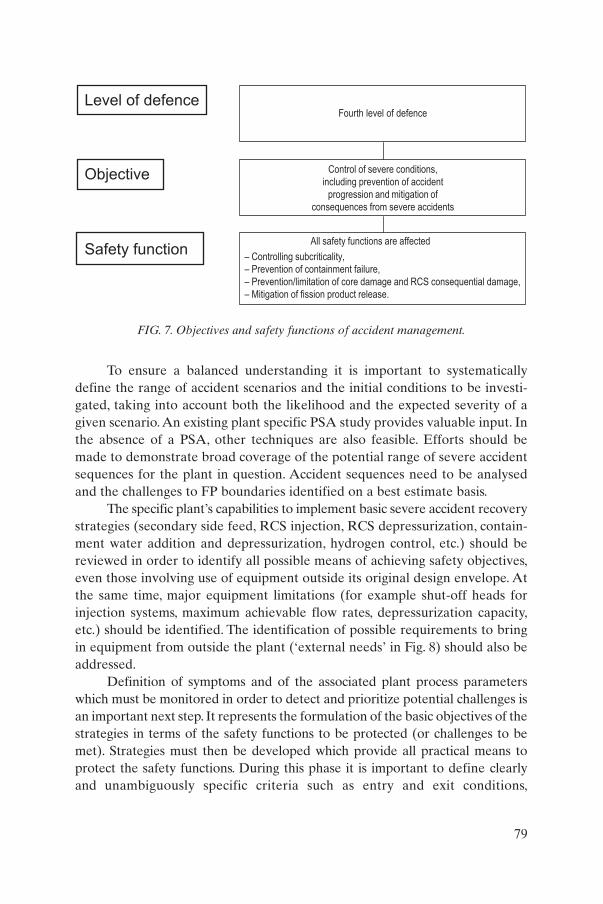
To ensure a balanced understanding it is important to systematicallydefine the range of accident scenarios and the initial conditions to be investi-gated, taking into account both the likelihood and the expected severity of agiven scenario. An existing plant specific PSA study provides valuable input. Inthe absence of a PSA, other techniques are also feasible. Efforts should bemade to demonstrate broad coverage of the potential range of severe accidentsequences for the plant in question. Accident sequences need to be analysedand the challenges to FP boundaries identified on a best estimate basis.
The specific plant’s capabilities to implement basic severe accident recoverystrategies (secondary side feed, RCS injection, RCS depressurization, contain-ment water addition and depressurization, hydrogen control, etc.) should bereviewed in order to identify all possible means of achieving safety objectives,even those involving use of equipment outside its original design envelope. Atthe same time, major equipment limitations (for example shut-off heads forinjection systems, maximum achievable flow rates, depressurization capacity,etc.) should be identified. The identification of possible requirements to bringin equipment from outside the plant (‘external needs’ in Fig. 8) should also beaddressed.
Definition of symptoms and of the associated plant process parameterswhich must be monitored in order to detect and prioritize potential challenges isan important next step. It represents the formulation of the basic objectives of thestrategies in terms of the safety functions to be protected (or challenges to bemet). Strategies must then be developed which provide all practical means toprotect the safety functions. During this phase it is important to define clearlyand unambiguously specific criteria such as entry and exit conditions,
79
Fourth level of defence
Control of severe conditions,
including prevention of accident
progression and mitigation of
consequences from severe accidents
All safety functions are affected
– Controlling subcriticality,
– Prevention of containment failure,
– Prevention/limitation of core damage and RCS consequential damage,
– Mitigation of fission product release.
Level of defence
Objective
Safety function
FIG. 7. Objectives and safety functions of accident management.

80
Challenges
Mechanisms
Provisions
Safety functions
Incompletereview of NPP
full designcapabilities
– Control of subcriticality,– Limitation of core damage,– Limitation of consequential damage,– Prevention of containment failure,– Mitigation of fission product release. RCS–
Inadequateaccident
managementstrategies
AM strategyinadequate
Objectives ofAM strategiesnot specifiedadequately
Unclearspecificationof external
needs
Identifyequipmentoutside its
design range
Determineneeds forexternalmaterial
Definecriteria
Decide uponprevention
and mitigation
Defineentry and exit
conditions
Develop alist of strategies
Set-upstrategy forsubcriticality
Ensureavailability of
external material
Determine theperformanceoutside range
Evaluate theinfluence of
support systemfailure
Determine theconsequences
of equipment failure
List equipmentable to accomplish
functions
Listpotentialdesign
modifications
Identifyalternativeequipment
Restorationof core cooling
Protectionof RCS integrity
Treatment ofcombustible
gases
Protectionof containment
integrity
Minimizingradioactivity
releases
Definediagnostic
meansand tools
Prove theeffectivenessof astrategy
Define mechanismsfor tracking
long term actions
Use userfriendly format
(flow chart)
Validatestrategies
Performindependent
review
FIG. 8. Objective trees for the accident management. Safety principle: strategy for accident management.

diagnostic symptoms, etc. Efforts should also be made to demonstrate that thelist of strategies developed is complete. The ‘correctness’ and the usability of the various strategies must be checked by an appropriate verification and validationprogramme. A severe accident will lead to the need to monitor and control various plant parameters in the very long term, even after the event has beencontrolled and the structured guidance terminated. A means should be definedfor identifying, tracking and monitoring these long term concerns.
VI.2.2. Performance of equipment in accident management (group 2)
A major part of accident management is associated with assessing theavailability of equipment and instrumentation, and recovering failed equip-ment. The ability of equipment and instrumentation to operate outside itsdesign basis depends on many factors but should be assessed during the devel-opment of the AMP (Fig. 9).
Environmental conditions which will be experienced by equipment willbe known from previous analyses and should be used to assist in evaluating thelikely response of the equipment and the survivability of instrumentation.Where possible, the operability margin of equipment beyond its design basiscan be estimated and factored into the evaluation. For instrumentation, thenumber of plant parameters which need to be monitored should be clearlydefined (and minimized, consistent with achieving the aims of the AMP),together with an assessment of all available means to measure those parame-ters and their likely survivability under severe accident conditions.
There is no single approach to addressing the need for new equipment foraccident management. In general, while the implementation of an AMP maygenerate requirements for limited upgrades (for example extending the rangesof certain instruments), the requirement for major equipment changes will notnormally be generated here. Level 1 PSA, for example, offers a means of decid-ing on the need for equipment upgrades. However, the assumed plant configu-ration basis, together with any resulting recommendations for upgrades, mustbe clearly stated in the AMP.
Figure 9 presents a framework to help in reviewing the equipment aspectsof an AMP. It is presented under the main categories of quality and mainte-nance of equipment, instrumentation availability, equipment availability, andactuation (‘initiation’) and control of systems and equipment.
VI.2.3. Response of personnel in accident management (group 3)
Figure 10 illustrates the key aspects of defining the roles and responsibil-ities of personnel, of developing and implementing procedures and guidelines
81

82 Safety functions
Challenges
Mechanisms
Provisions
Ensure effectiveimplementation of QApractices developed
by manufacturer
Implementoperational QAprogramme in
the NPP
Perform peer reviewof operational
QA programme
Optimize frequencyand extent
of preventivemaintenance
Establish provisionsto avoid human
errors duringmaintenance
Perform periodic func-tional testing in
accordance withrequired reliability
Developschedules forinspections
Ensureinspectability
of safetyequipment
Perform qualificationtests, preferably withprototypes,combina-
tion with analysis
Determine and docu-ment as built
characteristicsof systems
Include as-builtcharacteristics into
limits and intooperator training
Consider designmargin forequipment
performance
Consider feasibledesign changes
of equipment
Specify reserveor replaceable
equipment
Extend therange of
indicationsby instruments
Arrange protectionof instruments
against damagein severe conditions
Ensure availabilityof important informa-
in CR and EOP
Ensure functioningof instrumentationin station blackout
conditions
Separate normaland emergencyinstrumentationand monitoring
Develop userfriendly
format ofinformation
Develop andvalidate procedures
for initiation ofsystems
Ensure reliabilityof electrical, fluid,instrumentation
supporting systems
Provide, wherepossible, automatic
self testing
Determine timemargins for startup
of systems
Ensure reliablecommunicationamong remote
locations
Establish one or moresupplementary places
with monitoring andcontrol capability
Ensure diversepower and coolantsupply for station
blackout conditions
– Controlling subcriticality,– Limitation of core damage,– Limitation of RCS consequential damage,– Prevention of containment failure,– Mitigation of fission product release
Develop computational aidsto compensate for
insufficient instrumentation
Address need for special-equipment to mitigate severe
accidents (venting,H2 recombiners)
Install instrumentationprovided specifically foraccident management
Verify with manufactureroperability of equipment con-
sidering pressure, temperatureradiation, humidity, etc.
Equipment required in accident management
does not perform as intended
Quality of equipment inadequate
Maintenanceand
surveillanceinadequate
Equipment qualification/ performance inadequate
Insufficient monitoring of the plant
status
Unreliable initiation of equipment operation
Loss of control
capability
Install warningof the
habitability of the CR
Install automatic systems for limitation of core damage and radioactivity release
Evaluate performanceof instrumentation
beyond itsoperational range
Specify environmentalconditions for severeaccidents in different
locations
Develop programmeand proceduresfor maintenanceand surveillance
Select reliablemanufacturer with
independent verificationof its capabilities
Develop adequatecontrol and complementary
measures for disablingsafety systems
Establish independentverification of QA
programme in manufacturerorganization
Ensure power supplyto important instrumentation
for stationblackout conditions
Provide protectiveequipment for
operators
FIG. 9. Objective trees for accident management. Safety principles: automatic shutdown system, preservation of control capability, stationblackout, achievement of quality, quality assurance in operation, maintenance, testing and inspection, equipment qualification, verificationof design and construction, pre-operational plant adjustment, engineered features for accident management.

for accident management, and of training on-site emergency staff responsiblefor using the tools in case of an accident.
Organizational aspects of accident management are extremely important and very plant specific. It is important to define the roles of thedifferent parts of the emergency organization early in the programme devel-opment (primarily operations, technical support, emergency planning and response), and how these roles may be modified by changes or enhance-ments to the emergency response capability. Responsibility for evaluation,decision making and implementation must be assigned to the various accident management functions. It can be helpful to develop a matrix show-ing which member(s) of the organization are responsible for each of the different accident management functions. Defining decision making respon-sibility (i.e. responsibility for final authorization of a given course of action)is particularly important. It is generally recommended that, at least in severeaccident situations, those responsible for performing plant evaluations and recommending recovery strategies be a different group from those responsi-ble for implementing them.
The development of EOPs, SAMGs or similar systems entails the con-version of high level strategies into easily usable procedures or guidelines.Emergency operating procedures and SAMGs should be fully symptom based.They may or may not address specific accident scenarios in addition to pro-tecting the core by preserving safety functions or plant states. In general,SAMGs do not attempt to diagnose the specific sequence under way (a difficult task which is of little benefit), but rather provide a symptom based,structured way of determining which actions are needed to prevent challengesto the barriers to FP release and finally allow a controlled, stable plant state tobe achieved. The procedures and guidelines must be usable and workable (themain purpose of validation being to check these aspects), and they must be presented in a user friendly and consistent format which emergency staff canbecome fully familiar with and feel comfortable using.
The last column in Fig. 10 deals with various aspects of training which willbe required for the emergency staff. The development of an AMP must includea systematic identification of the training needs of personnel carrying out eachfunction of the emergency response team. The development of the requiredtraining material and the schedule for the training, re-training and testing ofstaff must also be defined. In the case of SAMGs, the phenomenology of the severe accident should be covered during the training of operating organization personnel, but the topics covered and the level of detail devotedto each should be chosen carefully, always keeping the overall objective of thetraining in mind.
83

84
Safety functions
Challenges
Mechanisms
Provisions
– Control of subcriticality,– Limitation of core damage,– Limitation of consequential RCS damage,– Prevention of containment failure,– Mitigation of fission product release.
Inadequateresponse of personnel
in BDBAs
Familiarize thestaff with the resultsof severe accident
analysis for the NPP
Personnelassignmentnot effective
enough
Symptom basedemergency operating
procedures notdeveloped adequately
Severe accidentmanagement
guidelinesinadequate
Trainingprogrammeinadequate
Review emergencyorganization and
qualificationof personnel
Specify scenarioscontributingsignificantly
to risk
Define proceduresfor all strategiesand check theireffectiveness
Define trainingneeds fordifferent
personnel
Involve emergencystaff in
functional testsof equipment
Develop a userfriendly format
of SAMG
Define plant statesto be covered byEOPs and their
symptoms
Developa list
of requiredqualifications
Provide sufficienthuman resources
for accidentmanagement
Propose andverify recovery
actions forDBAs and BDBAs
Check completenessof procedures
vs. strategies foraccident management
Cover detailsof phenomenology
of severeaccidents
Check the availabilityof information neededto detect level/trend
of severity
Check the availabilityof information
to detect the level andtrend of severity
Define linesof responsibilityand authority
for all personnel
Establish ateam of specialists
to adviseoperators
Verify the performanceof required
equipment undersevere conditions
Verify the performanceof equipmentrequired for
each strategy
Include relevantplant walk-through
in training
Make AMPdevelopment
material availablefor training
Verify theaccessibility of
equipment neededfor strategies
Define the conditionsfor operatorinvolvement
Develop acall-onsystem
for personnel
Define exitconditionsand further
steps
Define the expectedeffect and possiblenegative effects for
each strategy
Arrange forregular retraining
and testingof personnel
Ensure the availabilityof software tools
for validationand training
Define entry andexit conditions
for each strategyand further steps
Perform validationof EOPs for
DBAs and forselected BDBAs
Check EOPs forflexibility due to
uncertaintiesin BDBAs
Performvalidationof SAMG
Check the consistencyof proceduresand guidelineswith simulation
FIG. 10. Objective trees for accident management. Safety principles: validation of operat-ing and functional test procedures, training and procedures for accident management.
VI.2.4. Operational excellence and physical plant protection (group 4)
The objective tree for these two safety principles is shown in Fig. 11. Inthis particular case, the two principles have nearly no connection and have beencombined only to optimize the use of space.
As described in Ref. [1], operational excellence includes augmenting thesafety culture, defence in depth, improving human performance, using self-assessment and peer reviews, exchanging operational experience and otherinformation worldwide, increasing application of probabilistic safety assess-ment and augmenting the implementation of severe accident management.Many aspects of operational excellence have already been reflected in otherobjective trees. Several remaining aspects are presented here.
Effective feedback of operating experience is essential for all levels ofdefence in depth. This is also true for the majority of provisions shown in Fig. 11. Special attention should be given to lessons learned from analysis orconsideration of severe accidents or their precursors which have occurred insimilar plants. The results of emergency drills and exercises should also be utilized for updating the AMP.
Insufficient physical protection of the plant (plant security issues) canprovide possibilities of illegal acts against plant safety. On the other hand,physical protection should not jeopardize accessibility of the plant and/or itslocations to authorized personnel.
VI.2.5. Interface with off-site emergency planning (group 5)
All aspects of accident management related to off-site emergency plan-ning are reflected in Fig. 12. The organization, facilities, tools, staffing, responsi-bilities, qualification and training of the on-site emergency centre staff must allbe established and described in the emergency plan, and may be modified whenthe AMP is updated or enhanced.
It is wise to keep a clear distinction between the responsibilities andduties of personnel responsible for the off-site implications and personnel dealing with recovery of the plant, although the on-site emergency centre willnormally be the focal point of both activities.
The emergency plan itself should be reviewed to ensure that the requiredinstitutional arrangements are clearly laid out, including definition of theorganization, responsibilities, staffing, qualification, etc. of the ERT. The emergency plan must also clearly specify the interfaces between the on-siterecovery actions (for example, between the EOPs and the SAMGs), andbetween on-site and off-site activities.This should address the arrangements forpromptly informing and co-ordinating with off-site officials in the event that
85

86
Safety functions
Challenges
Mechanisms
Provisions
– Control of subcriticality,– Limitation of core damage,– Limitation of consequential RCS damage,– Prevention of containment failure,– Mitigation of fission product release.
Ensure consistencyof the modifications
to the plant hardware,procedures and training
Feedback of operatingexperience inadequate
for BDBAs
Provisionsof operational
excellenceinadequate
NPP vulnerableto externallegal acts
System for collectionand dissemination ofinformation on events
insufficient
System for analysisof events and
countermeasuresinadequate
Specific aspectsof BDBAs
not addressedadequately
Insufficient motivationfor safety orientedhuman behaviour
Physical protectioninsufficient against
illegal acts
Physical protectionaffecting the efficiencyof accident manage-ment programmes
Ensure accessibilityof equipment for emergency
team staff
Consider probableplant damage
from illegal acts
Establish safetyculture policy,
assess and implementmeasures
Establish a systemto develop
reliability datafor risk assessment
Establish a system foranalysis
of operationalevents
Establish internalreporting systemwithin the NPP
Develop poolingof informationwith operators
of similar plants
Include analysisof events in
regular trainingof personnel
Compareoperationalevents withPSA studies
Ensure early detectionof equipment
deterioration, includingageing effects
Establish sufficientredundancy of
equipment localizedin different locations
Ensure accessibilityof the NPP to
external experts
Verify that physicalprotection is not
jeopardizing EOPsand SAMGs
Establish securityhardware,
guards insidethe NPP
Arrange plantsafety assessments
and peer reviews
Performanalysis of
severe accidentprecursors
Perform a trendanalysis for earlyidentification ofdegradations
Establish proceduresfor external
reporting of operatingevents
Defineconditions for the
severity ofevents
Establish a systemfor implementingmeasures againstrecurring events
Consider lessonslearned from BDBAswhich have occurred
elsewhere
Provide for adequatemaintenance and
transfer of expertise
Establish physicalprotection of vital
facilities outside theNPP
Verify the efficiencyof physical protection
by drills
Establish a preferencefor safety
over operating cost
Establish mechanismsfor updates to AMPs
resulting fromdrills/exercises
Perform analysesof adverse effects
of proposedNPP modifications
Reinforce safetyoriented human
behaviourand teamwork
FIG. 11. Objective trees for accident management. Safety principles: operational excellence, physical plant protection.
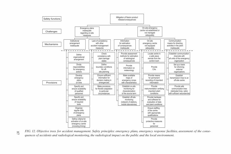
87
Safety functions
Challenges
Mechanisms
Provisions
Mitigation of fission productrelease/consequences
Emergency plansinadequate
regarding on-sitemeasures
On-site emergencycentre not established or
not managedadequately
Communicationmeans for directingactivities in the plant
inadequate
On-siteemergency centre
not equippedadequately
Informationfor estimation
of consequencesinadequate
Lack of consistencywith other
accident managementmeasures
Institutionalarrangementinadequate
Defineorganizationalarrangement
Checkconsistency with
plant damagestates
Provide assessmentmethods for estimation
of radiologicalconsequences
Locate centre ina safe place
remote from thecontrol room
Establish communicationchannels with
all units of the emergencyorganization
Set up a basisfor informing
externalorganizations
ProvideCAs
Provideinformation onmeteorology
Define boundary conditions
for off-site planning
Divideresponsibilitiesfor emergency
actions
Developemergency
planson time
Ensure sufficientinformation for
decision making inemergencies
Make availablemaps of
emergency zoneswith characteristics
Provide meansfor permanent
recording of importantinformation
Establishtransmission lines to an
off-site centre
Provide safecommunication lines
(dedicated lines, radio)with sufficient redundancies
Provideinstrumentation verifying
important plantconditions
Establish on-sitemonitoring for
characterizationof the source term
Make provisionsfor flexible adaptation
to particularcircumstances
Specify andensure availability
of qualifiedpersonnel
Specify andensure availability
of requiredtools
Establish off-sitemonitoring
(network of stations,mobile laboratories)
Provide hardwareand software for
evaluation of dataand plant conditions
Ensure staffingof the centrewith appropriatequalifications
Organizeregular drills
of emergencyplans
Define criteria foractivation of on-siteemergency centre(including timing)
Provideprotective measures
forpersonnel
FIG. 12. Objective trees for accident management. Safety principles: emergency plans, emergency response facilities, assessment of the conse-quences of accidents and radiological monitoring, the radiological impact on the public and the local environment.
any accident management action may result in either an increased off-site riskor an actual radioactive release.The interface with the off-site arrangements forproviding support on the site (e.g. for fire fighting) also needs to be addressed.In assessing the consistency of the emergency plan, systematic consideration ofall such interfaces is essential.
The adequacy of the on-site emergency centre can be assessed by meansof three key aspects: information needs, tools, and communications. The secondhalf of the figure suggests important elements to be considered when review-ing each of these.
VI.2.6. Emergency heat removal and ultimate heat sink provisions (group 6)
Technical and procedural means to ensure emergency heat removal andtransfer to the ultimate heat sink are reviewed by applying the objective treeshown in Fig. 13. These strategies play a crucial role, first in preventing the acci-dent from progressing to core degradation and later in preventing the RCS(lower head failure and induced SG tube ruptures) and containment failurewhich this would induce.
These strategies are challenged by recriticality, since emergency systemsare designed only for decay heat removal, and by inadequate operation ofemergency systems to remove the decay heat. The AMP should address allthese challenges and mechanisms.
The principal strategy for preventing core heat-up is to ensure secondaryside bleed and feed by any available means and, if this is not successful, to tryto ensure coolant injection into the reactor circuit. However, care should betaken not to cause recriticality by injection of non-borated water after meltingout of the control elements from the core region. Reactor circuit depressuriza-tion plays a crucial role, as it presents an interface between preventive accidentmanagement and the mitigation of the consequences if injection to the reactoris not successful.
VI.2.7. Protection of the containment structure (group 7)
The objective tree in Fig. 14 describes technical and procedural means ofpreventing containment failure during a severe accident. This safety functionplays a crucial role in mitigating the environmental consequences if core has not been successfully prevented.
The integrity of the containment integrity is challenged by pressure andtemperature loadings and missiles created by explosive severe accident phenomena. The AMP should address all the challenges and mechanisms.
88

89
Safety functions
Challenges
Mechanisms
Provisions
Inadequate heatremoval from
the containment tothe ultimate heat sink
– Control of subcriticality,– Limitation of core damage,– Limitation of consequential RCS damage,– Prevention of containment failure.
RecriticalityInadequatecore cooling
Inadequateheat removal
from thereactor circuit
Unavailabilityof the ultimate
heat sink
Slow overpressuredue to
steam generation
Inducedsteam generator
tube ruptureLower head failure
Hydrogengeneration
Core heat-upand relocation
Excessive heat intocontainment dueto neutron power
generation
Use boric waterfor core cooling
Secondaryside
bleed & feed
Preventcore
heat-up
In-vesselcooling of core
debris by injectioninto the vessel
Feed steamgenerators
Internalspray
Make provisionsto re-establish theultimate heat sink
Externalspray
Depressurizationof the RCS
In-vesselretention by
externalcooling
Depressurizationof the RCS
Inject waterinto the core
by anymeans
Depressurizationof the RCS
Filteredventing
Suppressionpool cooling
Sump cooling
Fans
FIG. 13. Objective trees for accident management. Safety principles: emergency heat removal, ultimate heat sink provisions.
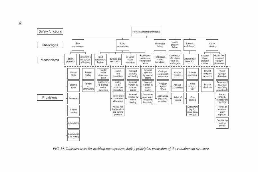
90
Safety functions
Challenges
Mechanisms
Provisions
Prevention of containment failure
Slowoverpressure
Rapidpressurization
Penetrationfailure
Under-pressure
failure
Basematmelt-through
Internalmissiles
Missiles fromex-vesselexplosive
phenomena
In-vesselsteam
explosionmissiles
Core concreteinteraction
Condensationafter releaseof non-con-
densible gases
Temperatureinduced
degradation
Rapid steamgeneration
during vesselfailure
Ex-vesselsteam
explosions
Burnable gascombustion
Directcontainment
heating
Generation ofnon-conden-sible gases
Steamgeneration
Internalspray
Filteredventing
Reactorcircuit
depressuri-zation
Ignitersand
recombiners
Timing ofcavity/dry
well flooding
In-vesselretention
by externalcooling
Cooling ofcontainmentatmosphere
Vacuumbreakers
Enhancespreading
Preventenergetic
explosions
Preventhydrogendetonation
Protection ofsteel shellfrom falling
concrete walls
Enforcestructures
Floodcavity/dry
well
Add non-condensibles
Protectionagainstflames
In-vesselretention by
internalflooding
In-vesselretention by
externalcooling
Inerting of the
containmentatmosphere
Add barriersto minimize
coriumdispersion
Ignitersand
recombiners
Externalspray
Fan coolersMixing of thecontainmentatmosphere
In-vesselretention by
internalflooding
Ensure ade-quate steamflow pathsfrom cavity
Add barriers(e.g. sumpprotection)
Switch offcooling
Corecatchers
PreventHPME by
depressurizingthe RCS
Prevent anex-vessel
steamexplosion
Add barriers(e.g. for
cavity doors,sumps)
Filtered ven-ting to reducepre-burning
pressure
Filteredventing
Sump cooling
Suppressionpool cooling
Consider theneed forbarriers
FIG. 14. Objective trees for accident management. Safety principles: protection of the containment structure.

The provisions to be applied should be defined consistently to eliminatethe challenges to the containment integrity. Figure 14 gives a structuredoverview of the possible strategies for protecting the containment. Which pro-visions will be applied by the AMP depends on national requirements, on thespecific plant and on the operating organization. The review should examinethe basis for the selected accident management provisions and assess theiroverall adequacy for protection of the containment.
VI.2.8. Confinement of radioactive material (group 8)
The safety function for mitigation of FP releases is reviewed by consider-ing the risks of FP dispersion (i.e. source term into the containment and sourceterm into the environment), FPs in the containment atmosphere and eventualrelease from the sump water.
Most FPs are released in aerosol form, with the exception of noble gasesand some forms of iodine. There are various aerosol retention mechanisms onthe release route from the reactor to the containment, in the containmentatmosphere and finally on the release route from the containment to the envi-ronment. The most effective retention mechanisms are scrubbing effects whenaerosols pass the water pool and the sprays. In some cases deposition in pipesmay be efficient, and in the case of hygroscopic aerosols gravitational settlingfrom the containment will quickly approach saturation conditions. Chemicaladditives to the spray also help in washing the iodine from the containmentatmosphere.The effect of noble gases is greatest if they are released to the envi-ronment early in the accident.
Two classes of provisions are listed in Fig. 15. Most of them aim at enhanc-ing the inherent aerosol retention and iodine scrubbing mechanisms and aretherefore helpful in mitigating releases. The main task of accident managementis to prevent containment failure due to physical phenomena which arereviewed by a separate objective tree, shown in Fig. 14. When a major contain-ment failure has been prevented, releases due to normal leakage, as well asfrom major leakages (resulting from an impaired containment function, i.e. iso-lation failure, or pre-existing opening) and containment bypass sequencesshould have been mitigated. Level 2 PSA studies should also give specialemphasis on minimizing the releases from such sequences.
VI.3. REVIEW PROCEDURE
The objective tree approach is intended to be used for self-assessment bythe plant operators or for an independent assessment by another reviewer. The
91

92
Safety functions
Challenges
Mechanisms
Provisions
Mitigation of fissionproduct release
Source term into the
environment
Fissionproduct
release fromwater
Fissionproducts in
containmentatmosphere
Source terminto the
containment
Releasethrough thequench tank
Failure of the RCSboundary
Lower headfailure
Aerosoldispersion
Gaseousdispersion
Low pH
Excessivesump watertemperature
Designleakage
fromcontainment
Impairedcontainment
function
Containmentfailure dueto physical
phenomena
Containmentbypass
sequences
InducedSG tubefailure
Feed steamgenerators
Depressurizethe RCS
Preventcontainment
failure
Provisionto monitorisolationstatus
Sumpcooling
Add baseOperatesprays
Operatesprays
Prevent MCCIaerosols
by floodingdebris
Quenchtank
scrubbing
Auxiliarypressurizer
spray
Filtersystem
Sprayadditives
Recovercontainment
isolation
Develop andapply PRISEmanagement
Depressurizethe RCS
Identify abypass routeand provideFP retention
Depressurizethe
containment
Flood thecontainment
leak
FIG. 15. Objective trees for accident management. Safety principles: confinement of radioactive material.

reviewer is expected to compare provisions identified in the objective trees tothe capabilities and provisions of the plant, to evaluate whether they exist andhow they are being implemented. The bottom-up method of screening individ-ual provisions is used. A judgment should be made of the level of implementa-tion of each particular provision in design, assessment and operation to preventmechanisms from challenging safety functions and/or control mechanisms. If asatisfactory answer to the implementation of each provision belonging to thespecific mechanism has been given, the relevant mechanism can be consideredto be prevented from occurring.
As mentioned previously, not all of the provisions shown in the objectivetrees should be considered absolutely necessary for the completeness of theAMP; in fact, some of the provisions are optional. It is up to the reviewer tojudge whether or not the absence of a provision actually leads to a weakness indefence in depth.
The approach described in this appendix cannot be used as a standalonedocument. More explanations can be found in Refs [1, 3, 9].
93

Appendix VII
TRANSITION FROM THE EOP DOMAIN TO THE SEVERE ACCIDENT MANAGEMENT GUIDANCE DOMAIN
Once conditions of existing or imminent core damage exist, a transitionfrom the EOP domain to the severe accident management guidance domaintakes place. Several approaches to this transition are possible. Some of the USand European approaches are described below.
VII.1. THE WOG SAMG
In this approach the EOP domain is left when certain conditions exist andan irreversible transition to the SAMG occurs. Conditions indicating actual orimminent core damage are included in the EOP and once they exist, the EOPdomain is left.
In the EOP domain the operator follows the functional restoration guide-lines (FRGs). One of the major FRGs is C1. It directs the operator to respondto a high core temperature. Several levels are identified, with increasing levelsof response. A temperature above 650°C plus notification that no ECCS isavailable is defined as the exit condition from FRG C1.A similar exit conditionexists for the subcriticality safety function. An exit condition from event ori-ented procedures also exists. If the operator notices the loss of all alternatingcurrent (AC) power, he or she must leave the EOP domain. Table IV gives anoverview of the different exit conditions from the EOP domain. The actual exitconditions are incorporated in the EOPs.
Whether or not the SAMGs are actually followed depends on the abilityof the TSC to function since it assumes all responsibility according to the WOGSAMG approach. The CR operators follow their instructions to execute theSAMGs. As long as the TSC is not available, operators have specific guidanceas to how to control the accident by the best possible means. These instructionsare contained in separate guidelines, called severe accident control room guide-lines (SACRGs). Guideline SACRG1 describes the actions to be taken as longas the TSC is not functional, SACRG2 directs operator actions once the TSC isfunctional. Once the shift supervisor determines that the TSC is functional (i.e.present and capable of making evaluations and decisions), responsibility istransferred.
94
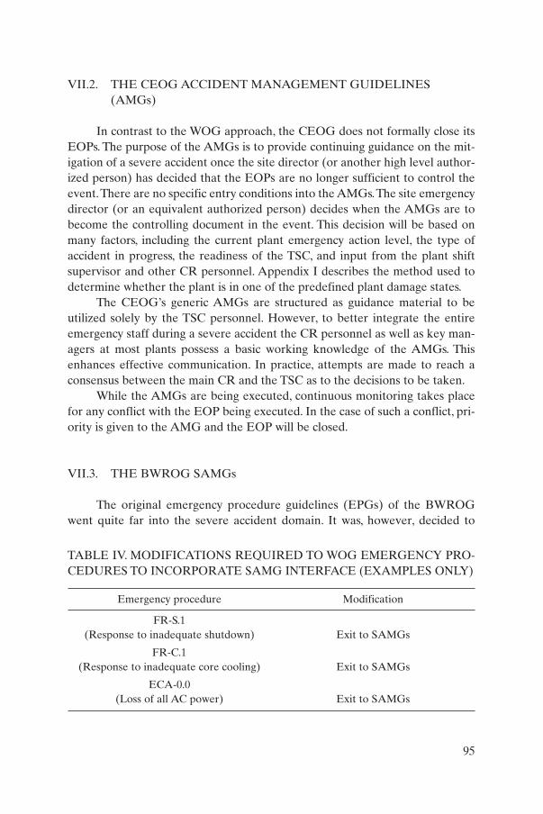
VII.2. THE CEOG ACCIDENT MANAGEMENT GUIDELINES(AMGs)
In contrast to the WOG approach, the CEOG does not formally close itsEOPs. The purpose of the AMGs is to provide continuing guidance on the mit-igation of a severe accident once the site director (or another high level author-ized person) has decided that the EOPs are no longer sufficient to control theevent.There are no specific entry conditions into the AMGs.The site emergencydirector (or an equivalent authorized person) decides when the AMGs are tobecome the controlling document in the event. This decision will be based onmany factors, including the current plant emergency action level, the type ofaccident in progress, the readiness of the TSC, and input from the plant shiftsupervisor and other CR personnel. Appendix I describes the method used todetermine whether the plant is in one of the predefined plant damage states.
The CEOG’s generic AMGs are structured as guidance material to be utilized solely by the TSC personnel. However, to better integrate the entireemergency staff during a severe accident the CR personnel as well as key man-agers at most plants possess a basic working knowledge of the AMGs. Thisenhances effective communication. In practice, attempts are made to reach aconsensus between the main CR and the TSC as to the decisions to be taken.
While the AMGs are being executed, continuous monitoring takes placefor any conflict with the EOP being executed. In the case of such a conflict, pri-ority is given to the AMG and the EOP will be closed.
VII.3. THE BWROG SAMGs
The original emergency procedure guidelines (EPGs) of the BWROGwent quite far into the severe accident domain. It was, however, decided to
95
TABLE IV. MODIFICATIONS REQUIRED TO WOG EMERGENCY PRO-CEDURES TO INCORPORATE SAMG INTERFACE (EXAMPLES ONLY)
Emergency procedure Modification
FR-S.1 (Response to inadequate shutdown) Exit to SAMGs
FR-C.1(Response to inadequate core cooling) Exit to SAMGs
ECA-0.0 (Loss of all AC power) Exit to SAMGs
decouple the severe accident phase and give the associated guidance in a set ofseparate SAMGs. The EPGs contain a set of procedures, including contingen-cies, for cases when normally available systems are not operable. If, for exam-ple, the water level in the RPV cannot be maintained using the normal EOPs,a contingency is entered called ‘alternate level control’, which makes use of avariety of sources, including unconventional ones. If, even using this contin-gency, the level cannot be kept above a certain minimum (called the minimumsteam cooling water level, i.e. the level at which the core, although already part-ly uncovered, is still cooled by upflowing steam), it becomes clear that coredamage is imminent. This is the moment when the EPGs are exited and theSAGs are entered. The transition, therefore, formally takes place when SAG-1,the integrated RPV and containment flooding guideline, is entered.At this timetotal responsibility shifts to the TSC. The EPGs will no longer be used.
VII.4. EMERGENCY GUIDELINES AT SIEMENS REACTORS,GERMANY
Siemens NPPs have two sets of manuals, the operations manual (OM)and the accident management manual (AMM).The AMM includes BDBAs notnecessarily associated with core damage, e.g. bleed and feed is a major proce-dure in the AMM. Use of the AMM commences when the safety functions canno longer be controlled using the OM procedures.
VII.5. ELECTRICITÉ DE FRANCE REACTORS, FRANCE
As stated in Appendix I, French reactors employ a family of procedures,called I, A, H and U, for increasing severity of an event (i.e. with an increasingnumber of failed safety functions).
When the core exit temperature exceeds 1100°C or the radiation level inthe containment goes beyond a predefined level, the transition to the SAMGsoccurs. The transition is decided upon by the safety engineer, a person whosededicated function is to oversee CR operations. A separate organizationbecomes active in the case of severe accidents. This consists of a number of crisis teams, both on-site and off-site. Responsibility is shifted to this crisis organization.
96

Appendix VIII
USE OF PSA IN SAMG DEVELOPMENT
VIII.1. USE OF PSA IN SEVERE ACCIDENT MANAGEMENT
Probabilistic safety assessment plays an important role in the develop-ment of severe accident management. It is used in the preparatory part, theselection of suitable strategies, the development of the actual severe accidentmanagement guidance, and in drills and training. In addition, it serves the needsof the on- and off-site emergency organizations by giving an indication of thepotential releases caused by severe accidents. The following sections deal withthese roles in greater detail.A detailed picture of the use of PSA in severe acci-dent management guidance is given in Ref. [22].
VIII.2. PREPARATION OF SEVERE ACCIDENT MANAGEMENT
As discussed in the main text, the development of a SAMG starts with aninvestigation of the plant’s vulnerabilities to identify those scenarios for whichsuch guidance should be developed. It may also be determined at this time forwhich very low probability scenarios no guidance needs to be developed asthey belong to the area of acceptable residual risk. Level 1 and level 2 PSAs willidentify the core damage and core melt phenomena that are relevant for theparticular plant or group of plants.
VIII.3. THE STRATEGY SELECTION PROCESS
VIII.3.1. Derivation of the severe accident insights needed for SAMGdevelopment
Depending on the analysis outlined in Section 1, those processes whichare relevant for the specific plant should be selected and those which are irrel-evant should be discarded, e.g. it may appear that steam explosions have a verylow probability or that hydrogen deflagration will not pose a challenge to thecontainment. Consequently, these phenomena need not be considered furtherin the selection of suitable strategies unless certain operator actions will makethem relevant again. For example, if the scenario predicts that an ex-vessel
97
steam explosion will not occur if the cavity is dry, the situation may change ifthe operator floods the cavity.
VIII.3.2. Technical basis for candidate strategies
Based on the insights gained from Sections 2 and 3, candidate strategiescan be defined which are in essence derived from the CHLAs discussed inSection 4 (and in Appendix II). Thus, if it is known from the preparatory analy-sis that a high pressure melt ejection may lead to failure of the containment,depressurization of the RPV becomes an important strategy. Similarly, if it isfound that flooding the cavity or the dry well may cool the debris in the vessel,such flooding becomes a candidate strategy.
This study should investigate the effects of the different CHLAs on thevarious plant damage descriptors (see Appendix I) to either predict the posi-tive outcome of the potential action or the negative consequence of it.Theoretically, the effect of all CHLAs during all plant damage descriptors canbe studied. In practice, the number of studies is limited as not all actions are rel-evant for all plant damage states. The phenomenological part of the PSA ismainly used for this. Dedicated mechanistic severe accidents codes (MAAP,MELCOR, etc.) can also be used.
VIII.3.3. Selection of strategies
Based on the insights gained from Sections 4.1 and 4.2, strategies can bedeveloped to mitigate the relevant accident scenarios. The strategies couldeventually be fed back into the PSA to estimate their benefit and, thus, verifythe usefulness of the proposed action. A severe limitation of this is that a realevent has many uncertainties, many decision points and many ramifications,making such feedback complicated and its result highly uncertain.
VIII.4. DEVELOPMENT OF SAMGs
VIII.4.1. Entry and exit set points
After the strategies have been defined, the actual guidelines need to bedeveloped. They have entry and exit conditions. Probabilistic safety assessmentmay serve to find the conditions both to enter the SAMG domain and to leavethe EOP domain as the only or the dominant accident management tool.Insights from PSA can be used to obtain such set points; for example the entryinto SAMGs may occur at a core exit temperature of 650°C. This value must be
98
such that the SAMG actions which follow make sense and attain their objec-tives. For example, an empty SG must be flooded at a rate at which SG tubecreep rupture will be prevented. Such insights are obtained from PSA typeanalyses.
VIII.4.2. Computational aids
Quantitative information to support the TSC (or related group) can alsobe obtained from PSA, such as the amount of water that will prevent vesselmeltthrough (for BWRs, the minimum debris retention injection rate), theamount of water needed to effectively spray the containment, or the effect ofcontainment venting on the flammability of hydrogen in the containment.
VIII.4.3. Priorities
A severe accident may easily lead to a situation calling for simultaneousexecution of all available guidelines. However, some guidelines are moreimportant in such situations and these can be identified with PSA.
VIII.5. DRILLS AND TRAINING
Drills are usually based on suitable templates. They should cover the rel-evant scenarios and call for many of the SAMGs to be executed. A PSA is anexcellent tool to develop those templates.
VIII.6. DETERMINATION OF SOURCE TERM/DOSE RATE TO THEENVIRONMENT
A level 3 PSA gives estimates of the source term and its external conse-quences. As the execution of the SAMG during the severe accident will have agreat influence on the outcome of the accident in terms of releases, a reliableprediction using PSA is not possible. However, it may appear that the initiatingevent with its initial complications is fairly well known. The associated PSAsource term may then serve as an upper estimate of the potential release.
99

REFERENCES
[1] INTERNATIONAL NUCLEAR SAFETY ADVISORY GROUP, Basic SafetyPrinciples for Nuclear Power Plants 75-INSAG-3 Rev. 1, INSAG-12, IAEA,Vienna (1999).
[2] INTERNATIONAL NUCLEAR SAFETY ADVISORY GROUP, Defence inDepth in Nuclear Safety, INSAG-10, IAEA, Vienna (1996).
[3] INTERNATIONAL ATOMIC ENERGY AGENCY, Accident ManagementProgrammes in Nuclear Power Plants: A Guidebook, Technical Reports SeriesNo. 368, IAEA, Vienna (1994).
[4] INTERNATIONAL ATOMIC ENERGY AGENCY, Safety of Nuclear PowerPlants: Design, Safety Standards Series No. NS-R-1, IAEA, Vienna (2000).
[5] INTERNATIONAL ATOMIC ENERGY AGENCY, Accident Analysis forNuclear Power Plants, Safety Reports Series No. 23, IAEA, Vienna (2002).
[6] ELECTRIC POWER RESEARCH INSTITUTE, Severe Accident ManagementGuidance, Technical Basis Report, Vols 1 & 2, Rep. EPRI TR-101869, EPRI, PaloAlto, CA (1992).
[7] FOOD AND AGRICULTURE ORGANIZATION OF THE UNITEDNATIONS, INTERNATIONAL ATOMIC ENERGY AGENCY, INTERNA-TIONAL LABOUR ORGANIZATION, OECD NUCLEAR ENERGYAGENCY, PAN AMERICAN HEALTH ORGANIZATION, UNITEDNATIONS OFFICE FOR THE CO-ORDINATION OF HUMANITARIANAFFAIRS, WORLD HEALTH ORGANIZATION, Preparedness and Responsefor a Nuclear or Radiological Emergency, Safety Requirements, Safety StandardsSeries No. GS-R-2, IAEA, Vienna (2002).
[8] NUCLEAR REGULATORY COMMISSION, Assessment of CandidateAccident Management Strategies, Rep. NUREG/CR 5474, US Govt PrintingOffice, Washington, DC (1992).
[9] COMMITTEE ON THE SAFETY OF NUCLEAR INSTALLATIONS,Implementing Severe Accident Management in Nuclear Power Plants, Rep.OECD/GD(97)198, OECD, Paris (1997).
[10] COMMITTEE ON THE SAFETY OF NUCLEAR INSTALLATIONS,Specialist Meeting on Severe Accident Management Implementation, Rep.OECD/NEA/CSNI/R(95)5, OECD, Paris (1995).
[11] INTERNATIONAL ORGANIZATION FOR STANDARDIZATION, QualityManagement and Quality Assurance, Rep. ISO 9000/1-4, ISO, London (1994).
[12] INTERNATIONAL ATOMIC ENERGY AGENCY, Quality Assurance forSafety in Nuclear Power Plants and Other Nuclear Installations: Code and SafetyGuides, Q1–Q14, Safety Series No. 50-C/SG-Q, IAEA, Vienna (1996).
[13] LUTZ, R.J., Westinghouse Owners Group — Severe Accident ManagementGuidance Validation, Rep. WCAP-14213, Westinghouse Electric Corporation,Pittsburgh (1994).
[14] HOLDERBAUM, D.F., Koeberg Nuclear Plant — Severe Accident ManagementGuidance Validation, Rep. WCAP-14603, Westinghouse Electric Corporation,Pittsburgh, PA (1996).
101
[15] NORTH ANNA POWER STATION, Severe Accident Management GuidelineDemonstration Programme, Virginia Power, Richmond, VA (1997).
[16] DUANE ARNOLD ENERGY CENTER,Technical Support Guidelines (TSGs),Training Material, IES Utilities Inc., Cedar Rapids, MI (1998).
[17] HENRY, S.A., Assessment of Severe Accident Management Training Drill,Calvert Cliffs Nuclear Power Station, Rep. NEU 98-130, Baltimore Gas & ElectricCorporation, Cusby, MD (1998).
[18] INTERNATIONAL ATOMIC ENERGY AGENCY, Guidelines for the Reviewof Accident Management Programmes in Nuclear Power Plants, Services SeriesNo. 9, IAEA, Vienna (2003).
[19] INSTITUTE OF NUCLEAR POWER OPERATIONS, A Systematic Approachto Training, Training Program Handbook DOE-HDBK-1078-94, INPO, Atlanta(1994).
[20] HODGSON, C.D., “The management of severe accidents — Eskom position”,Severe Accident Management (Proc. Expert Mtg Lyon, 1996), WANO, London(1996).
[21] NUCLEAR REGULATORY COMMISSION, Instrumentation for Light-Water-Cooled Nuclear Power Plants to Assess Plant and Environs Conditions Duringand Following an Accident, Rep. NUREG 1.97, Rev. 3, US Govt Printing Office,Washington, DC (1983).
[22] COMMITTEE ON THE SAFETY OF NUCLEAR INSTALLATIONS,Implementing Severe Accident Management in Nuclear Power Plants, Rep.OECD/GD(97)198, OECD, Paris (1997).
102
Annex I
SUMMARY OF INTERNATIONAL ACTIVITIES IN SEVERE ACCIDENT MANAGEMENT
The subject of accident management programmes (AMPs) has alreadybeen covered by a number of IAEA publications. The IAEA has sponsoredwork on the development of operating procedures for accident conditions andon the practical implications of source term reassessment. In 1985 and 1988,the IAEA convened advisory groups on accident management. The results ofthis work were published in Refs [I–1, I–2]. In 1985, the IAEA sponsored asymposium on Source Term Evaluation for Accident Conditions and in 1988,together with the OECD Nuclear Energy Agency (OECD/NEA), a symposiumon Severe Accidents in Nuclear Power Plants [I–3]. A number of Technical Co-operation meetings were held on the following topics:
(a) Use of PSA results for accident management (1989),(b) Symptom oriented emergency operating procedures (1990),(c) Containment performance (1990),(d) Containment filtering and venting (1991),(e) Severe accident management (1997, 1998).
Co-ordinated Research Projects on accident management and contain-ment integrity and effectiveness for accident conditions were also sponsored inthe period from 1994 to 1996. Additional information on the subject can befound in Refs [I–4 to I–6].
Information on the efforts being made, particularly in OECD MemberCountries, and on typical strategies implemented to prevent or mitigate the con-sequences of core melting, is available, for example, from a report entitledImplementing Severe Accident Management in Nuclear Power Plants [I–7].Thatreport summarizes the situation in representative OECD Member Countries andcan be used as a starting point for the development of further plant specific AMPs.
The European Commission (EC) has contracted a study1 on severe acci-dent management, entitled SAMIME, with the objective of determining thestatus and the extent of severe accident management development inEuropean Union (EU) countries and developing a consensus among the part-ners as to which elements are needed or useful, as well as defining what furtherresearch work is needed to support severe accident management development[I–8]. The project was completed in 2000 [I–9].
103
1 Formally called a ‘concerted action’ under the Fourth Framework Programme.
In 1994 the IAEA published a report on Accident ManagementProgrammes in Nuclear Power Plants [I–10], which was designed as a guidebookto provide a systematic, structured approach to the development and implemen-tation of an AMP.The main emphasis of this guidebook, which was developed bya consortium of consultants during the early 1990s, is on generic accident management guidance, including evaluation of vulnerabilities, accident manage-ment strategies, symptom oriented EOPs, training and organization. Since thatIAEA report was published, a great effort has been made to implement plantspecific AMPs in a large number of LWR plants. Accident management programmes have been implemented in all US NPPs and corresponding work isat an advanced stage in many European countries. The present report can beunderstood, to a certain extent, as an update of the previous report [I–10], reflect-ing knowledge gained from the implementation process of AMPs.
REFERENCES TO ANNEX I
[I–1] INTERNATIONAL ATOMIC ENERGY AGENCY, Developments in thePreparation of Operating Procedures for Emergency Conditions of NuclearPower Plants, IAEA-TECDOC-341, Vienna (1985).
[I–2] INTERNATIONAL ATOMIC ENERGY AGENCY, Some PracticalImplications of Source Term Reassessment, IAEA-TECDOC-451,Vienna (1988).
[I–3] INTERNATIONAL ATOMIC ENERGY AGENCY, Severe Accidents inNuclear Power Plants (Proc. Symp. Sorrento, 1988), IAEA, Vienna (1988).
[I–4] OECD NUCLEAR ENERGY AGENCY, Specialist Meeting on Severe AccidentManagement Programme Development, Rep. NEA/CSNI/R(91)16, ENEA,Rome (1992).
[I–5] OECD NUCLEAR ENERGY AGENCY, Instrumentation to Manage SevereAccidents (Proc. Specialist Mtg Cologne, 1992), Gesellschaft fürReaktorsicherheit, Cologne (1992).
[I–6] NUCLEAR REGULATORY COMMISSION, Summary of a Workshop onSevere Accident Management, Rep. NUREG/CR-5780/5781, US Govt PrintingOffice, Washington, DC (1991).
[I–7] COMMITTEE ON THE SAFETY OF NUCLEAR INSTALLATIONS,Implementing Severe Accident Management in Nuclear Power Plants,Rep. OECD/GD(97)198, OECD, Paris (1997).
[I–8] EUROPEAN UNION, Concerted Actions on Severe Accident ManagementImplementation and Expertise in the European Union, SAMIME, Contract F145-CT98-0652 (1998).
[I–9] EUROPEAN COMMISSION, FISA ’99 — EU Research in Reactor Safety(Proc. Symp. Luxembourg, 1999), EC, Luxembourg (1999).
[I–10]INTERNATIONAL ATOMIC ENERGY AGENCY, Accident ManagementProgrammes in Nuclear Power Plants: A Guidebook, Technical Reports SeriesNo. 368, IAEA, Vienna (1994).
104
Annex II
OVERVIEW OF THE SEVERE ACCIDENT MANAGEMENT GUIDANCE APPROACH AND
IMPLEMENTATION IN SOME MEMBER STATES
This annex gives an overview of approaches to SAMGs as they exist todate, with emphasis on developments in the USA and Europe. Greater atten-tion is given to the US approach as the USA has developed an extensive set ofSAMGs which has now been implemented in all operating US NPPs and isbeing implementated in many NPPs in other countries. The information on theEuropean countries has been collected in Ref. [II–1] and has been made avail-able to the IAEA by the European Commission. It has been updated whereadditional information has become available from Member States. Separateinformation was provided by Japan. A wider but less recent overview, withmore technical detail, is available in Ref. [II–2].
II.1. UNITED STATES OF AMERICA
II.1.1. Early developments
Following the completion of actions to ensure correction of safety andemergency response issues experienced during the Three Mile Island (TMI)accident, both the industry and the regulatory body took the initiative toanalyse and evaluate generic issues related to the accident. One of these issuesconcerned radiological source terms; the actual releases during the TMI acci-dent did not reflect what existing accident scenarios had predicted.
The process that followed led to the development of revised design basisscenarios, revised design basis source terms addressed by the Nuclear RegulatoryCommission (NRC) [II–3], the development of symptom based EOPs and, ulti-mately, to the recognition of the need for severe accident management.
In August 1985 the NRC published its policy statement regarding severereactor accidents [II–4]. This statement recognized the industry effort in severeaccident risk management and essentially supported this ongoing effort. Thiswas followed in 1988 by Report SECY-88-147 [II–5], which described the NRCplan for development and implementation (closure) of severe accident issues.This document also supported the approach of the NUMARC/(NEI) NuclearEnergy Institute programme. In 1989, Report SECY-89-012 [II–6] was issueddescribing the NRC approach to closure of the accident management guide-lines portion of the integration plan for severe accident management.
105

The industry process, which included international co-operation, wasmanaged by the NEI, with significant interaction among operating organiza-tions, the Institute of Nuclear Power Operations, the Electric Power ResearchInstitute (EPRI), owners groups, the NRC and recognized experts. Applicationwas seen mostly outside the formal regulatory environment and the focus wason developing severe accident management guidance for the existing stations,i.e. without consideration of other than minor hardware modifications. InDecember 1994, Report NEI 91-04, Rev.1 [II–7] was published, with an agree-ment among all US operating organizations to follow through with implemen-tation of these guidelines. The NRC concurred with this industry approach inJanuary 1995.
II.1.2. The US industry position
The goal of US severe accident management, as defined in Ref. [II–7], wasto enhance the capabilities of the emergency response organization (ERO) to mitigate severe accidents and prevent or minimize any off-site releases.The objective was to establish core cooling and ensure that any current orimmediate threats to the FP barriers were being managed. To accomplish this,the ERO was to make full use of existing plant capabilities, including standardand non-standard uses of plant systems and equipment.The position, which wasbinding for all NPPs in the country, reads as follows:
“Each licensee will:
• Assess current capabilities to respond to severe accident conditions usingSection 5 of NEI 91-04, Rev. 1, ‘Severe Accident Issue ClosureGuidelines’;
• Implement appropriate improvements identified in the assessment,within the constraint of existing personnel and hardware, on a schedule tobe determined by each licensee and communicated to the NRC, but inany event no later than December 31, 1998.”
II.1.3. The severe accident management closure process
Section 5 of Ref. [II–7] specifies the closure process for a given licensee inthe following four steps:
(1) Evaluate industry developed and owners group SAMGs along with theindividual plant examination (IPE) for external events and the plant’scurrent capabilities, to develop SAMGs for significant accidents and
106
screened with pre-specified criteria, and consider other generic and plantspecific information (e.g. NRC and industry studies, PSA results, etc.)where appropriate.
(2) Interface the SAMG with the plant’s emergency plan.(3) Incorporate severe accident material into appropriate training pro-
grammes.(4) Establish a means to consider and possibly adopt new severe accident
information from self-assessments by licensees, applicable NRC genericcommunications, PSA studies, etc.
Screening criteria were used which basically state that for sequences witha relatively large core damage frequency (CDF) or containment bypassfrequency, measures should be taken (i.e. administrative, procedural or hard-ware modification) which are mainly directed towards reducing the likelihoodof the source of the accident sequence initiator; for sequences with a relativelysmall CDF or containment bypass frequency, SAMGs should be in place.Below 1 × 10⁻⁶ per reactor-year for the CDF and below 1 × 10⁻⁷ per reactor-year for containment bypass frequency, no actions were required (i.e. noSAMGs would be required).
Since the development of these criteria, the US industry has gone beyondthis threshold and implemented severe accident management irrespective ofevent or sequence probability. Severe accident management is bounded solelyby the physical phenomena arising from severe accidents, i.e. all mechanistical-ly possible conditions are considered.
II.1.4. Development of SAMG strategies
The industry developed a technical basis for the selection and determina-tion of potential countermeasures. This was done by EPRI and documented inthe technical basis report (TBR). The purpose of the TBR was to provide anindustry-wide common technical basis, from which the owners’ groups and indi-vidual operating organization could develop their vendor and plant specificaccident management guidance. The TBR uses various plant damage condi-tions to describe a severe accident progression, along with their anticipatedsymptoms and related phenomena. The report is symptom, not event oriented.Hence, no event sequences were studied with their consequences and potentialramifications, but severe accident symptoms were sought and their sensitivityto a spectrum of potential countermeasures, the candidate high level actions(CHLAs), was investigated.
The different damage conditions of the core were summarized in threemajor core damage states. A similar concept was followed for the containment.
107
Fifteen CHLAs were defined and the TBR investigated the response of each ofthe core and containment damage states to each of the CHLAs. Later, threeadditional actions were considered: external cooling of the (RPV/RCS), steaminerting of the containment and in-vessel cooling. It was recommended thatthese should also be considered when developing plant specific guidance. Theprocess is described in further detail in Appendices I and II, where the individ-ual CHLAs and the plant damage states are identified.
The actual development of SAMGs was not attempted. This was left tothe owners groups and the individual operating organizations. These consid-ered the TBR results plus information from their probabilistic safety studies,i.e. IPEs or PSAs, and identified the areas which were of relevance for their sta-tions. From this material they developed generic strategies which were to be theessence of the plant’s methodology. Individual plants then transformed thisgeneric material into their plant specific procedures and guidelines.
II.1.5. Status of implementation
As already discussed, the US effort is based on the approaches of theowners groups. Hence, four groups of generic SAMGs have been developed,which have been transformed to plant specific guidance by the individual oper-ating organizations. Extensive verification and validation was done, partly withthe help of simulators, for the pre-severe accident management phase. Drillsand exercises were held which included peer review, i.e. personnel from otherstations was involved in review and assessment. The NRC oversaw the pro-gramme but did not formally approve the implementation of SAMGs. As of 31December 1998, all operating US stations had implemented SAMGs.
More detailed elements of the US Owners Groups guidance are con-tained in other parts of this report, such as the plant damage states, the transi-tion from the EOP-to the severe accident management domain, the list ofCHLAs, the logical diagrams used by the WOG and the CEOG among others,and computational aids where these elements appear as examples of industrialapplications of certain more general SAMG principles.
II.2. EUROPE
Developments in Europe have been more hardware oriented. Filteredcontainment vents were designed and installed in several countries; in somecountries, catalytic hydrogen recombiners were also installed. Equipment suchas power operated relief valves (PORVs) was requalified or replaced to makeit capable of withstanding loads from bleed and feed, etc. From a software pointof view, many plants performed PSAs or upgraded existing PSAs. However,
108
many countries have not yet established a formal severe accident managementprogramme, i.e. a full and comprehensive inclusion of core melt scenarios withall their associated phenomena in the procedures. This section highlights theapproaches in a number of European countries.
II.2.1. Belgium
Belgium has no uniform programme for development of SAMGs. Somestations follow US developments and have started development and imple-mentation of the WOG guidelines at the request of the regulatory body. Themethodology and lines of authority also follow the WOG approach. The WOGSAG is not used in those stations which have catalytic recombiners. Generally,strategies were selected based on level 1 and 2 PSA results, systems analysisand instrument analysis.
Some older stations have developed SAMGs independently, not inresponse to a request by their regulatory body. In these cases the EOPs are notclosed, but enhanced by additional SAGs. An example is the continuous moni-toring of water and power sources. Equipment that has failed is also broughtback into service. Core damage is not addressed as such in the procedures.
II.2.2. Netherlands
Since only one plant (Siemens design) is still in operation, its situation isthe only relevant one. Its management voluntarily elected to follow the WOGapproach since the regulatory body had requested severe accident proceduresbut had left the choice of method and vendor to the licensee. The plant decid-ed to not just follow the WOG, but to enhance this method with useful featuresof other US approaches, with the CEOG’s diagnostic tools and the BWROwners Group’s technical support guidelines as the candidates. This will bedone in an iterative process, i.e. after implementation of the WOG method assuch.
II.2.3. Sweden
Sweden completed its severe accident management programme in1988. It contained several hardware features (e.g. a filtered vent on the con-tainment), procedures and training. Westinghouse beyond emergencyresponse guidelines (BERGs) were developed and implemented in Sweden’sthree PWRs. In contrast to the modern WOG approach, they require therecognition of vessel failure. More recently, handbooks on severe accidentswere developed that are intended to be used in the TSC. These handbooks
109
contain severe accident insights plus some guidance. Exercises are limited;they are not focused on the use of SAGs, but more on communication pathsand effectiveness.
II.2.4. France
French reactors have a family of procedures, called I, A, H and U, forincreasing severity of an event (i.e. with an increasing number of failed safetyfunctions). I stands for ‘incidents’, A for ‘accidents’, H for ‘outside design’ andU for ‘ultimate procedures’. Examples of U procedures are U2, restoring thecontainment function and U5, containment venting. In recent years, state ori-ented procedures have been added, replacing event oriented EOPs in order tosupport the operators. There is no need for them to diagnose the initiatingevent.
For conditions indicating core damage, a set of SAGs is entered whichbasically centres around depressurization and feeding of the RPV,depressurization and feeding of the steam generator, and restoring contain-ment integrity using U2 and, ultimately, U5 procedures. French procedures donot explicitly address plant damage states (i.e. possible combinations of coreand containment damage states), but are oriented towards restoring criticalsafety functions (CSFs) on the basis of observed parameters and the availabil-ity of safety systems. Severe accidents are handled by on-site and off-site crisisteams which decide on the actions to be taken.
II.2.5. Spain
Spanish operating organizations follow the rules and regulations of thecountry of origin. Plants of US origin therefore follow the SAMG approach. Nodecision has yet been taken for the single Siemens plant, as Siemens inGermany have not yet taken such steps. It may follow the general philosophyof SAMG as it is applied by the other Spanish NPPs. The Spanish regulatorybody, Consejo de Seguridad Nuclear (CSN), has not explicitly requiredSAMGs.
In 1994 the Spanish PWR owners group presented a ‘common basisreport’ to the regulatory body, addressing SAMGs. Similarly, the BWR ownersgroup did the same in 1995. These documents are comparable to the US indus-try’s position. The association of Spanish operating organizations, AsociaciónEspañola de la Industria Eléctrica (UNESA), presented the case to the CSN in1996. A programme calling for SAMGs to be in place by the end of 2000 wasdeveloped and presented. For the Siemens plant, a later date may well bepossible.
110

II.2.6. United Kingdom
Severe accident prevention and mitigation strategies have been devel-oped and implemented at the single operating PWR, Sizewell B, and theadvanced gas cooled reactors (AGRs). The detailed design development ofSizewell B was undertaken in the period immediately following the TMI acci-dent, which highlighted the importance of dealing with beyond design basis sce-narios. The decision was therefore taken to produce a suite of operating proce-dures to cover all operating states from normal operation to severe accidents.In addition, the design benefited from insights derived from plant specific level3 PSAs.
Examples of design changes made include a ‘wet’ reactor cavity to miti-gate basemat failure and the incorporation of additional isolation valves in theRHR suction lines to reduce interfacing systems LOCA (so-called V sequence)frequency. Included in the Sizewell B station operating instructions (SOIs) area set of symptom based procedures (SOI 8) which are extended to severe acci-dent mitigation. The actions included in the severe accident mitigation proce-dures are associated with the use of existing plants in different modes and withrelaxed limits applied. Because severe accidents were considered in the plantdesign, it has not proved necessary to provide additional equipment for severeaccident management. Current international developments in severe accidentmanagement are closely monitored for any future upgrade of the SOIs.
In the case of the AGRs, the plants are equipped with an accident man-agement capability to deal with BDBAs. It includes a set of symptom basedemergency response guidelines (SBERGs) designed primarily to prevent coredamage. In the unlikely event that the SBERGs should fail, the emergency con-troller will refer to a set of advisory guidelines, the severe accident manage-ment guidelines, designed with the objective of mitigating activity release to theenvironment.
II.2.7. Germany
With respect to accident management, in Germany a distinct line is drawnbetween the design basis area and the beyond design basis area. Accidentswithin the design basis area are dealt with by so-called ‘event oriented proce-dures’ when the event is clearly identifiable by use of a decision tree. If this is not the case or if the selected procedure is not successful, a set of ‘symptomoriented procedures’ is employed. Both sets of procedures comprise the oper-ations manual (OM).
Accidents which have been identified as BDBAs are dealt with by usingthe so-called ‘beyond design basis operations manual’ (BDBOM). The
111

BDBOM is structured along the same lines as the symptom oriented part of theOM, i.e. it is based on the CSF concept.
The BDBOM includes preventive (core intact) as well as mitigatory pro-cedures (core damaged). The emphasis is, however, on the prevention side andlimited guidance is available for the core damage situation. Use is made notonly of existing hardware. Extensive new hardware has been installed to beable to carry out both preventive and mitigatory accident management. Bleedand feed of the secondary and/or primary side are examples of the former;filtered containment venting, catalytic recombiners and a sampling systemincluding H2 sampling are examples of the latter. Care has been taken that suchcomponents (e.g. PORVs) are fully qualified for their functions.
In order to implement accident management actions correctly, a clear setof criteria based on directly measurable physical quantities has to exist. Precisecriteria are available to the shift leader as to when to use event oriented procedures, when to switch to symptom oriented procedures, and when to beginusing the beyond design basis operating manual. Precise criteria for mitigatoryactions such as containment venting are also defined.
It should be noted that the efforts made by the German operating organ-izations in the beyond design basis area are voluntary. Operating organizationsand the Federal Government have, however, agreed that the recommendationsmade by the Reactor Safety Commission (RSK) in this area will be followed.
II.2.8. Slovakia
A major activity in Slovakia has been the transition from event based tosymptom based EOPs by means of emergency response guidelines (ERGs),which is being done with support from Westinghouse. It has included a criticalreview of the ERG strategies, which had to be adapted to the configuration andcharacteristics of WWERs (e.g. the generic EOP exit criterion of 650°C had tobe changed to 550°C). From there, SAMG development was initiated under aPHARE contract. A detailed investigation of WWERs under severe accidentconditions was carried out using MAAP4, which included characteristics of theWOG SAMG strategies for the WWERs.
The project has proceeded to the definition of logic trees, i.e. the decisionflow chart (DFC) and the severe challenge status tree (SCST) (see Appendix I)plus high level strategies and a proposal to upgrade instrumentation and con-trol (I&C) for severe accidents. This includes a requalification of selected I&Cequipment to severe accident conditions, i.e. it will be qualified for beyonddesign basis conditions, including some margin where appropriate (for example,core exit thermocouples up to 1000°C).
112
In addition to ERGs, which are in use at NPPs, a set of severe accidentmanagement documents has been prepared for the emergency response centreof the Nuclear Regulatory Authority of the Slovak Republic (UJD SR). At thepresent time, the emergency procedure for evaluation of severe accidents in theemergency response centre of UJD is being developed for the Mochovce NPPby the technical staff of the department for safety analysis and technical sup-port at the UJD SR.
A set of accident scenarios representing a spectrum of postulated severeaccidents for the Mochovce NPP has been analysed using the MELCOR severeaccident computer code. The analyses performed include thermal-hydrauliccore damage, FP release, FP transport and containment response during thepostulated accident conditions. The accident source term has been evaluated toestimate the radiological consequences. In the final phase, based on the analy-sis results, the emergency procedure for the emergency response centre of theUJD SR will be developed and used during emergency drills or real emergencysituations at units 1 and 2 of the Mochovce NPP.
The emergency procedures for the Jaslovske Bohunice NPP have beencompleted. Depending on the progress of reconstruction of the V-1 JaslovskeBohunice NPP, the emergency procedures for this plant will be updated.
II.2.9. Finland
In Finland two nuclear operating organizations independently operatetwo plants based on different concepts, a WWER-440 and an ABB BWR.Teollisuuden Voima Oy, the owner and operator of the Olkiluoto ABB BWRs,carried out a severe accident management project at the end of the 1980s, whichincluded several plant modifications and integration of SAMGs into the ulti-mate EOP. Fortum Engineering Ltd (formerly IVO) has developed a completesevere accident management approach applying the integrated risk orientedaccident analysis methodology for the Loviisa WWER-440 units. Following thisapproach, Fortum is in the process of developing SAMG documents in parallelwith plant modifications.
II.3. ASIA
II.3.1. Japan
Symptom based EOPs were developed in Japan in the 1980s after theTMI-2 accident. Conventional accident operating procedures (AOPs) wereinstalled, as well as hardware, e.g. wide range monitors. Level 1 and 2 PSAshave been extensively applied in Japan, both by the regulatory body and the
113
industry, and accident management measures have been developed whichaddress, for example, utilization of conventional systems, electric power supplyfrom an adjacent unit, alternate measures for reactivity control, water injection,heat removal and recovery of failed components. These measures were identi-fied on the basis of PSA results. The industry was to have implemented theseaccident management countermeasures around the year 2000.
For accident management at some plants in Japan AOPs, EOPs andsevere accident operating procedures (SOPs) have been prepared for use in theCR, and AMG and recovery procedures for RHR and D/G have been preparedfor use in the TSC, which is set up during an accident.The AMG is applied afterdetection of core damage. The AMG makes use of figures and graphs of ana-lytical results and shows the technical bases and criteria for identifying plantconditions, selecting proper accident management countermeasures and mak-ing evaluations. For the CR, SOPs which contain the most important aspects ofthe AMG used by the TSC are prepared using a flow chart format to allowquick responses. These accident management procedures are reviewed period-ically and improved to reflect the progress of knowledge in PSA and severeaccident research. Similar approaches are being considered for other plants.
REFERENCES TO ANNEX II
[II–1] EUROPEAN COMMISSION, FISA ’99 — EU Research in Reactor Safety(Proc. Symp. Luxembourg, 1999), EC, Luxembourg (1999).
[II–2] COMMITTEE ON THE SAFETY OF NUCLEAR INSTALLATIONS,Implementing Severe Accident Management in Nuclear Power Plants, Rep.OECD/GD(97)198, OECD, Paris (1997).
[II–3] NUCLEAR REGULATORY COMMISSION, Severe Accident Risk: AnAssessment of Five US Nuclear Power Plants, Rep. NUREG-1150, US GovtPrinting Office, Washington, DC (1990).
[II–4] NUCLEAR REGULATORY COMMISSION, Policy Statement on SevereAccidents Regarding Future Designs and Existing Plants, NRC Policy Statement50FR 32138, Federal Register, US Govt Printing Office, Washington, DC (1985).
[II–5] STELLO, V., Integration Plan for Closure of Severe Accident Issues, Rep. SECY-88-147, Nuclear Regulatory Commission, US Govt Printing Office, Washington,DC (1988).
[II–6] STELLO, V., Staff Plans for Accident Management Regulatory and ResearchPrograms, Rep. SECY-89-012, Nuclear Regulatory Commission, US Govt PrintingOffice, Washington, DC (1989).
[II–7] NUCLEAR ENERGY INSTITUTE, Severe Accident Issue Closure Guidelines,Rep. NEI 91-04, Rev. 1, NEI, Washington, DC (1994).
114

Annex III
TYPICAL TSC ORGANIZATION AT A BWR IN THE USA
At Alliant Energy’s Duane Arnold Energy Center NPP, the TSC has beenorganized as depicted in Fig. III–1. The accident management team (AMT) oraccident assessment team (AAT) has been added to the original TSC, as can beseen from Fig. III–1. In this scheme, the operations supervisor holds a reactoroperator licence and is the prime contact between the AMT and the CR inorder to facilitate communications between the TSC and the CR.
115
Operations liaison(EPG/SAG
assessment)
QualityAssurance
OSC/WCCsupervisor
EmergencyCo-ordinator
Operationssupervisor
Engineeringsupervisor
Site radiationprotection
co-ordinator
Supportservices
supervisor
Chemistrytechnicians
Electricalsupervisor
+electricians
Securitysupervisor
Radiationprotection
support staff
Engineeringsupport
Shiftmanager
Operating crew(system
assessment)
Accidentmanagement
team I&Cengineer
MIDASoperator
Informationservices
representative
Mechanicalsupervisor
+mechanics
WCC/TSC/CRcommunicator
Healthphysics
supervisor
I&Csupervisor
+I&C techniciansCommunicators
HPNcommunicator
Mechanicalengineer
Communicators Reactor engineer(core assessment)
Electricalengineer
Field teamradio operators
Materialco-ordinatormanagement
Administrativeco-ordinator
Health physicstechnicians
ORAL/ODEFsupervisor
Healthtechnicians
physics
Chemistrytechnicians
ORAAsupervisor
Healthphysics
technicians
Securityforce
Safety analysisengineer (plant
status assessment)
ENScommunicator
Electronic statusboard recorder
CR/TSC/WCC CRback panel
On-site/Off-site
Clerical staff SPDS operator(parameter
assessment)
FIG. III.1. Emergency response organization scheme of the Duane Arnold NPP (USA).ENS: emergency notification system (the primary means of communicating reactor safe-ty related information throughout an emergency from the licensee to the NRC); EPG:emergency procedure guidelines; HPN: health physics notification (the primary means ofcommunicating radiological data from the licensee to the NRC); MIDAS: meteorologicalequipment; SAG: severe accident guidelines; SPDS: safety parameter display system;ODEF: off-site decontamination facility; ORAA: off-site relocation and assembly area;ORAL: off-site radiological and analytical laboratory; OSC: operational support centre;WCC: work control centre (where the OSC is established during an emergency andresponsible for establishing and controlling in-plant assessment and repair teams).
DEFINITIONS
The definitions were compiled solely for the purpose of the present report.The list does not represent a consensus or an endorsement by the IAEA.
accident. Any unintended event, including operating errors, equipment failuresor other mishaps, the consequences or potential consequences of whichare not negligible from the point of view of protection or safety.
accident management. The taking of a set of actions during the evolution of abeyond design basis accident: to prevent the escalation of the event intoa severe accident; to mitigate the consequences of a severe accident; andto achieve a long term safe stable state.
accident management programme. Plans and actions undertaken to ensure thatthe plant and the personnel with responsibilities for accident manage-ment are adequately prepared to take effective on-site actions to preventor to mitigate the consequences of a severe accident.
arrangements (for emergency response). The integrated set of infrastructuralelements necessary to provide the capability for performing a specifiedfunction or task required in response to a nuclear or radiological emer-gency.These elements may include authorities and responsibilities, organ-ization, co-ordination, personnel, plans, procedures, facilities, equipmentor training.
beyond design basis accident (BDBA). Accident conditions more severe than adesign basis accident. (A BDBA may or may not involve core degradation.)
computational aid. Pre-calculated analyses, nomographs or easily used computersoftware available for use by plant staff during a severe accident:(1) to support plant staff guidance, (2) to predict accident phenomena andtiming, and (3) to evaluate the effectiveness of specific candidate strategies.
containment. Methods or physical structures designed to prevent the disper-sion of radioactive substances.
design basis accident (DBA). Accident conditions against which a nuclearpower plant is designed according to established design criteria, and forwhich the damage to the fuel and the release of radioactive material arekept within authorized limits.
emergency. A non-routine situation or event that necessitates prompt action,primarily to mitigate a hazard or adverse consequences for human healthand safety, quality of life, property or the environment. This includesnuclear and radiological emergencies and conventional emergencies suchas fires, release of hazardous chemicals, storms or earthquakes. It includessituations for which prompt action is warranted to mitigate the effects ofa perceived hazard.
117
emergency operating procedures. Plant specific procedures containing instruc-tions to operating staff for implementing measures to prevent core degra-dation in both DBAs and BDBAs.
emergency plan. A description of the objectives, policy and concept of opera-tions for the response to an emergency and of the structure, authoritiesand responsibilities for a systematic, co-ordinated and effective response.The emergency plan serves as the basis for the development of otherplans, procedures and checklists.
emergency procedure. A set of detailed written instructions describing theactions to be taken by response personnel in an emergency.
emergency response. The performance of actions to mitigate the consequencesof an emergency for human health and safety, quality of life, property andthe environment.
event specific procedure. A procedure containing actions which are appropri-ate only for a specific accident sequence (or set of sequences) which mustbe diagnosed before applying the procedure. An event specific proceduremay or may not be symptom based.
guideline. A text setting out actions to mitigate or stabilize accident conditions.mitigatory action. Immediate action by the operator or another party: (1) To
reduce the potential for conditions to develop that would result in expo-sure or a release of radioactive material requiring emergency actions onor off the site; or (2) To mitigate source conditions that may result inexposure or a release of radioactive material requiring emergency actionson or off the site.
probabilistic safety assessment (PSA). A comprehensive, structured approachto identifying failure scenarios, constituting a conceptual and mathemati-cal tool for deriving numerical estimates of risk. Three levels of PSA aregenerally recognized. Level 1 comprises the assessment of plant failuresleading to the determination of core damage frequency. Level 2 includesthe assessment of containment response leading, together with level 1results, to the determination of containment release frequencies. Level 3includes the assessment of off-site consequences leading, together withthe results of level 2 analysis, to estimates of public risks.
procedure. A set of detailed written instructions to direct actions. The actionsshould be carried out in the sequence laid down in the procedure unlessotherwise indicated in the procedure body or by the rules for use of a document.
response organization. An organization designated or otherwise recognized bya State as being responsible for managing or implementing any aspect ofan emergency response.
118
severe accident. Accident conditions more severe than a design basis accident,involving significant core degradation.
severe accident management guidelines. A set of guidelines for actions forsevere accident management.
strategy. A group of activities developed at a plant with the common objectiveof preventing and/or mitigating the effects of severe accidents.
symptom based procedure/guideline. A procedure or guideline for actions to betaken depending on the values of directly measurable plant parameters.
validation. The process of determining whether a product or service is adequateto perform its intended function satisfactorily. (The evaluation is per-formed to determine whether the actions specified in the instructions ofan accident management programme can be executed by trained staff tomanage emergency events.)
verification. The process of determining whether the quality or performance ofa product or service is as stated, as intended or as required. (The evalua-tion is performed to confirm the correctness of a written procedure orguideline to ensure that technical and human factors have been properlytaken into account.)
vulnerability. Any combination of plant design features and operations whichcould lead to a severe accident or could inhibit the ability to prevent ormitigate a severe accident.
119
CONTRIBUTORS TO DRAFTING AND REVIEW
Fagula, L. Bohunice NPP, Slovakia
Gustavsson, V. Vattenfall Energisystems AB, Sweden
Misak, J. International Atomic Energy Agency
Prior, R. Westinghouse Energy Systems Europe S.A.,Belgium
Sonnenkalb, M. Gesellschaft für Anlagen- undReaktorsicherheit, Germany
Tuomisto, H. Fortum Engineering Ltd, Finland
Vayssier, G. NSC–Nuclear Safety Consultancy,Netherlands
Walsh, L.A. Seabrook NPP, United States of America
Consultants Meetings
Vienna, Austria: 3–7 November 1997, 18–22 May 1998,19–23 October 1998,
26–30 July 1999, 15–19 November 1999
121


