Journal of Loss Prevention in the Process Industries 14 (2001) 139–151 www.elsevier.com/locate/jlp Safety strategy against potential hazards due to the handling of powders in a blending unit Norbert Jaeger * Safety Testing Laboratory, Ciba Specialty Chemicals, Additives Division, McIntosh, AL, USA Abstract To ensure and maintain process safety in the chemical industry a systematic hazard search and evaluation, i.e. “Risk Analysis” is indispensable. The knowledge of the ignition behavior of dust-air is important for such a risk assessment in a chemical production plant. This paper describes, based on a practical example, the strategy of performing a Risk Analysis and the use of the minimum ignition energy and minimum auto ignition temperature as very important safety indexes in practice. 2001 Elsevier Science Ltd. All rights reserved. Keywords: Minimum ignition energy; Dust explosion hazards; Hazard evaluations; Electrostatic discharges 1. Introduction The knowledge of the ignition behavior of dust–air mixtures is important for risk assessments in chemical production plants. This paper describes the systematic approach in searching for dust explosion hazards, the appropriate use of technical measures to eliminate the previous identified hazards or their reduction of the severity to an accept- able level. Preventive measures against the occurrence of electro- static discharges and mechanically generated sparks dur- ing powder handling operations will be also described by using practical examples from a blending unit for powders. The aim of this paper is to assist people dealing with powders. It reflects the present state of the art and current knowledge of the assessment and measures associated with powder handling. 2. Process description The blend unit is designed to produce two or three component blends for sale as powder and as a feed for * Current address: Home and Fabric Care, Ciba Specialty Chemi- cals, Consumer Care Division, Grenzach, Germany. Tel.: + 49-0-7624- 12-2235. E-mail address: [email protected](N. Jaeger). 0950-4230/01/$ - see front matter 2001 Elsevier Science Ltd. All rights reserved. PII:S0950-4230(00)00036-X a granulation unit. The blend components are manufac- tured in separate process units, adjacent to the granu- lation unit. All the components are conveyed with N 2 through pneumatic conveying systems into storage silos. Blend components are screw feed from surge bins into weigh hoppers. From there, the material can be trans- fened into a blender. Once the blend has been completed, the batch is discharged to a surge hopper and a new blend can be initiated. From the surge hopper the final blend can be transfered into the packaging facility for packaging in drums, FIBC’s and bulk containers. Fig. 1 shows a simplified schematic drawing of the unit. 3. Risk analysis Safety guidelines, regulations and technical instruc- tions facilitate control of the more commonly occurring safety problems. However, in practice, every chemical process constitutes a particular combination of chemi- cals, plant and process conditions, To ensure and main- tain process safety in the chemical industry, therefore, a systematic predictive hazard search and evaluation, i.e. ‘Risk Analysis’, is indispensable. Its objective is to obtain ‘synthetic experience’ before the technical implementation of processes or plant start-up so that from the outset planned, appropriate measures can be taken Ciba-Geigy, 1992. In evaluating Risk, consideration must be given to
Transcript
Journal of Loss Prevention in the Process Industries 14 (2001) 139–151www.elsevier.com/locate/jlp
Safety strategy against potential hazards due to the handling ofpowders in a blending unit
To ensure and maintain process safety in the chemical industry a systematic hazard search and evaluation, i.e. “Risk Analysis”is indispensable. The knowledge of the ignition behavior of dust-air is important for such a risk assessment in a chemical productionplant. This paper describes, based on a practical example, the strategy of performing a Risk Analysis and the use of the minimumignition energy and minimum auto ignition temperature as very important safety indexes in practice. 2001 Elsevier Science Ltd.All rights reserved.
The knowledge of the ignition behavior of dust–airmixtures is important for risk assessments in chemicalproduction plants.
This paper describes the systematic approach insearching for dust explosion hazards, the appropriate useof technical measures to eliminate the previous identifiedhazards or their reduction of the severity to an accept-able level.
Preventive measures against the occurrence of electro-static discharges and mechanically generated sparks dur-ing powder handling operations will be also describedby using practical examples from a blending unit forpowders.
The aim of this paper is to assist people dealing withpowders. It reflects the present state of the art and currentknowledge of the assessment and measures associatedwith powder handling.
2. Process description
The blend unit is designed to produce two or threecomponent blends for sale as powder and as a feed for
* Current address: Home and Fabric Care, Ciba Specialty Chemi-cals, Consumer Care Division, Grenzach, Germany. Tel.:+49-0-7624-12-2235.
0950-4230/01/$ - see front matter 2001 Elsevier Science Ltd. All rights reserved.PII: S0950-4230 (00)00036-X
a granulation unit. The blend components are manufac-tured in separate process units, adjacent to the granu-lation unit. All the components are conveyed with N2
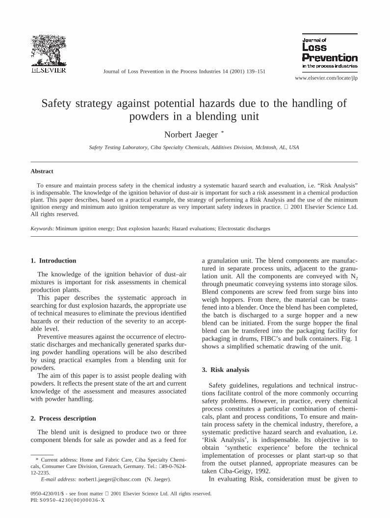
through pneumatic conveying systems into storage silos.Blend components are screw feed from surge bins intoweigh hoppers. From there, the material can be trans-fened into a blender. Once the blend has been completed,the batch is discharged to a surge hopper and a newblend can be initiated. From the surge hopper the finalblend can be transfered into the packaging facility forpackaging in drums, FIBC’s and bulk containers. Fig. 1shows a simplified schematic drawing of the unit.
3. Risk analysis
Safety guidelines, regulations and technical instruc-tions facilitate control of the more commonly occurringsafety problems. However, in practice, every chemicalprocess constitutes a particular combination of chemi-cals, plant and process conditions, To ensure and main-tain process safety in the chemical industry, therefore, asystematic predictive hazard search and evaluation, i.e.‘Risk Analysis’, is indispensable. Its objective is toobtain ‘synthetic experience’ before the technicalimplementation of processes or plant start-up so thatfrom the outset planned, appropriate measures can betaken Ciba-Geigy, 1992.
In evaluating Risk, consideration must be given to
140 N. Jaeger / Journal of Loss Prevention in the Process Industries 14 (2001) 139–151
Fig. 1. Blending unit.
both the Probability of occurrence of an incident and theSeverity of the consequences.
3.1. Systematic approach
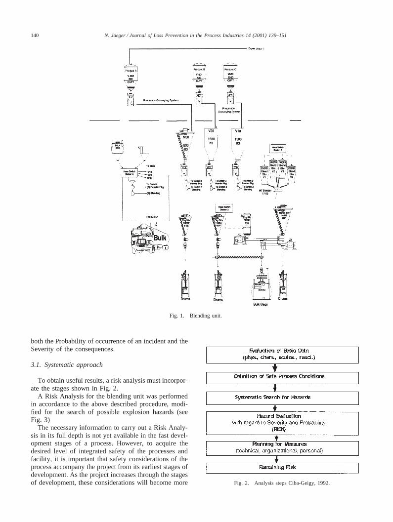
To obtain useful results, a risk analysis must incorpor-ate the stages shown in Fig. 2.
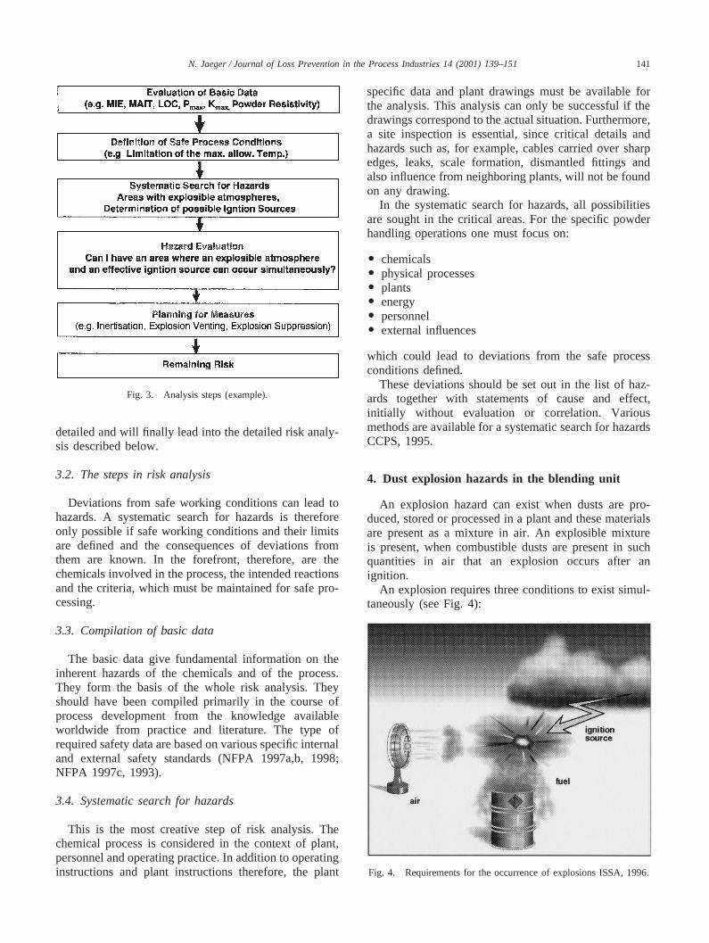
A Risk Analysis for the blending unit was performedin accordance to the above described procedure, modi-fied for the search of possible explosion hazards (seeFig. 3)
The necessary information to carry out a Risk Analy-sis in its full depth is not yet available in the fast devel-opment stages of a process. However, to acquire thedesired level of integrated safety of the processes andfacility, it is important that safety considerations of theprocess accompany the project from its earliest stages ofdevelopment. As the project increases through the stagesof development, these considerations will become more Fig. 2. Analysis steps Ciba-Geigy, 1992.
141N. Jaeger / Journal of Loss Prevention in the Process Industries 14 (2001) 139–151
Fig. 3. Analysis steps (example).
detailed and will finally lead into the detailed risk analy-sis described below.
3.2. The steps in risk analysis
Deviations from safe working conditions can lead tohazards. A systematic search for hazards is thereforeonly possible if safe working conditions and their limitsare defined and the consequences of deviations fromthem are known. In the forefront, therefore, are thechemicals involved in the process, the intended reactionsand the criteria, which must be maintained for safe pro-cessing.
3.3. Compilation of basic data
The basic data give fundamental information on theinherent hazards of the chemicals and of the process.They form the basis of the whole risk analysis. Theyshould have been compiled primarily in the course ofprocess development from the knowledge availableworldwide from practice and literature. The type ofrequired safety data are based on various specific internaland external safety standards (NFPA 1997a,b, 1998;NFPA 1997c, 1993).
3.4. Systematic search for hazards
This is the most creative step of risk analysis. Thechemical process is considered in the context of plant,personnel and operating practice. In addition to operatinginstructions and plant instructions therefore, the plant
specific data and plant drawings must be available forthe analysis. This analysis can only be successful if thedrawings correspond to the actual situation. Furthermore,a site inspection is essential, since critical details andhazards such as, for example, cables carried over sharpedges, leaks, scale formation, dismantled fittings andalso influence from neighboring plants, will not be foundon any drawing.
In the systematic search for hazards, all possibilitiesare sought in the critical areas. For the specific powderhandling operations one must focus on:
O chemicalsO physical processesO plantsO energyO personnelO external influences
which could lead to deviations from the safe processconditions defined.
These deviations should be set out in the list of haz-ards together with statements of cause and effect,initially without evaluation or correlation. Variousmethods are available for a systematic search for hazardsCCPS, 1995.
4. Dust explosion hazards in the blending unit
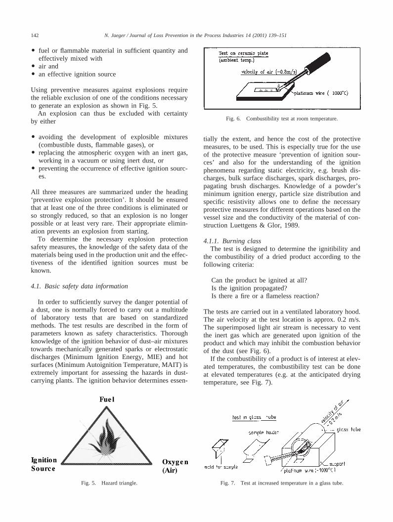
An explosion hazard can exist when dusts are pro-duced, stored or processed in a plant and these materialsare present as a mixture in air. An explosible mixtureis present, when combustible dusts are present in suchquantities in air that an explosion occurs after anignition.
An explosion requires three conditions to exist simul-taneously (see Fig. 4):
Fig. 4. Requirements for the occurrence of explosions ISSA, 1996.
142 N. Jaeger / Journal of Loss Prevention in the Process Industries 14 (2001) 139–151
O fuel or flammable material in sufficient quantity andeffectively mixed with
O air andO an effective ignition source
Using preventive measures against explosions requirethe reliable exclusion of one of the conditions necessaryto generate an explosion as shown in Fig. 5.
An explosion can thus be excluded with certaintyby either
O avoiding the development of explosible mixtures(combustible dusts, flammable gases), or
O replacing the atmospheric oxygen with an inert gas,working in a vacuum or using inert dust, or
O preventing the occurrence of effective ignition sourc-es.
All three measures are summarized under the heading‘preventive explosion protection’. It should be ensuredthat at least one of the three conditions is eliminated orso strongly reduced, so that an explosion is no longerpossible or at least very rare. Their appropriate elimin-ation prevents an explosion from starting.
To determine the necessary explosion protectionsafety measures, the knowledge of the safety data of thematerials being used in the production unit and the effec-tiveness of the identified ignition sources must beknown.
4.1. Basic safety data information
In order to sufficiently survey the danger potential ofa dust, one is normally forced to carry out a multitudeof laboratory tests that are based on standardizedmethods. The test results are described in the form ofparameters known as safety characteristics. Thoroughknowledge of the ignition behavior of dust–air mixturestowards mechanically generated sparks or electrostaticdischarges (Minimum Ignition Energy, MIE) and hotsurfaces (Minimum Autoignition Temperature, MAIT) isextremely important for assessing the hazards in dust-carrying plants. The ignition behavior determines essen-
Fig. 5. Hazard triangle.
Fig. 6. Combustibility test at room temperature.
tially the extent, and hence the cost of the protectivemeasures, to be used. This is especially true for the useof the protective measure ‘prevention of ignition sour-ces’ and also for the understanding of the ignitionphenomena regarding static electricity, e.g. brush dis-charges, bulk surface discharges, spark discharges, pro-pagating brush discharges. Knowledge of a powder’sminimum ignition energy, particle size distribution andspecific resistivity allows one to define the necessaryprotective measures for different operations based on thevessel size and the conductivity of the material of con-struction Luettgens & Glor, 1989.
4.1.1. Burning classThe test is designed to determine the ignitibility and
the combustibility of a dried product according to thefollowing criteria:
Can the product be ignited at all?Is the ignition propagated?Is there a fire or a flameless reaction?
The tests are carried out in a ventilated laboratory hood.The air velocity at the test location is approx. 0.2 m/s.The superimposed light air stream is necessary to ventthe inert gas which are generated upon ignition of theproduct and which may inhibit the combustion behaviorof the dust (see Fig. 6).
If the combustibility of a product is of interest at elev-ated temperatures, the combustibility test can be doneat elevated temperatures (e.g. at the anticipated dryingtemperature, see Fig. 7).
Fig. 7. Test at increased temperature in a glass tube.
143N. Jaeger / Journal of Loss Prevention in the Process Industries 14 (2001) 139–151
Table 1Definition burning classes
Test result Class Reference
No ignition No spreading of fire 1 Table saltBrief ignition, rapid extinction 2 Tartaric acidLocalized combustion or glowing with practically no spreading 3 D+LactoseGlowing without sparks (smoldering) or slow de-composition without flames Fire spreads 4 H-acidBurning fireworks or slow quiet burning with flames 5 SulfurVery rapid combustion with flame propagation or rapid decomposition without flame 6 Black powder
The combustibility of the product is rated in accord-ance with the course of reaction and characterized as aclass number (see Table 1).
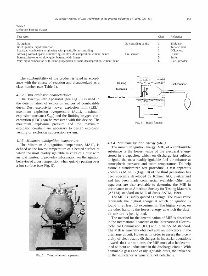
4.1.2. Dust explosion characteristicsThe Twenty-Liter Apparatus (see Fig. 8) is used in
the determination of explosion indices of combustibledusts. Dust explosivity, lower explosion limit (LEL),maximum explosion overpressure (Pmax), maximumexplosion constant (Kmax) and the limiting oxygen con-centration (LOC) can be measured with this device. Themaximum explosion pressure and the maximumexplosion constant are necessary to design explosionventing or explosion suppression system.
4.1.3. Minimum autoignition temperatureThe Minimum Autoignition temperature, MAIT, is
defined as the lowest temperature of a heated surface atwhich the most readily ignitable mixture of a dust withair just ignites. It provides information on the ignitionbehavior of a dust suspension when quickly passing overa hot surface (see Fig. 9).
Fig. 8. Twenty-liter-test apparatus.
Fig. 9. BAM furnace.
4.1.4. Minimum ignition energy (MIE)The minimum ignition energy, MIE, of a combustible
substance is the lowest value of the electrical energystored in a capacitor, which on discharge just sufficesto ignite the most readily ignitable fuel–air mixture atatmospheric pressure and room temperature. To helpassure a standardized test procedure, a test apparatusknown as MIKE 3 (Fig. 10) of the third generation hasbeen specially developed by Ku¨hner AG, Switzerlandand has been made commercial available. Other testapparatus are also available to determine the MIE inaccordance to an American Society for Testing Materials(ASTM) standard on MIE of dusts ASTM, 1999.
The MIE is usually quoted as a range: The lower valuerepresents the highest energy at which no ignition isfound in at least 10 experiments. The higher value, onthe other hand, is the lowest energy at which the dust–air mixture is just ignited.
The method for the determination of MIE is describedin the International Standard of the International Electro-technical Commission (IEC) and in an ASTM standard.The MIE is generally obtained with an inductance in thedischarge circuit. However, in order to assess the incen-divity of electrostatic discharges in industrial operationstowards dust–air mixtures, the MIE must also be determ-ined without an inductance in the discharge circuit. Withflammable gases and easily ignitable dusts, the influenceof the inductance is generally not detectable.
144 N. Jaeger / Journal of Loss Prevention in the Process Industries 14 (2001) 139–151
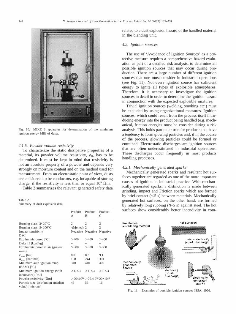
Fig. 10. MIKE 3 apparatus for determination of the minimumignition energy MIE of dusts.
4.1.5. Powder volume resistivityTo characterize the static dissipative properties of a
material, its powder volume resistivity,rR, has to bedetermined. It must be kept in mind that resistivity isnot an absolute property of a powder and depends verystrongly on moisture content and on the method used formeasurement. From an electrostatic point of view, dustsare considered to be conductors, e.g. incapable of storingcharge, if the resistivity is less than or equal 109 Vm.
Table 2 summarizes the relevant generated safety data
Table 2Summary of dust explosion data
Product Product ProductA B C
Burning class @ 20°C 2 2 2Burning class @ 100°C -(Melted) 2 2Impact sensitivity Negative Negative NegativeDSCExothermic onset [°C] .400 .400 .400Delta H [kcal/kg] – – –Exothermic onset in air (grewer .300 .300 .300oven)Pmax [bar] 8.0 8.3 9.1Kmax [bar×m/s] 158 244 301Minimum auto ignition temp. 340 440 400(BAM) [ °C]Minimum ignition energy (with .1,,3 .1,,3 .1,,3inductance) [mJ]Powder resistivity [Vm] .20×1012 .20×1012 20×1012
Particle size distribution (median 46 56 16value) [microns]
related to a dust explosion hazard of the handled materialin the blending unit.
4.2. Ignition sources
The use of ‘Avoidance of Ignition Sources’ as a pro-tective measure requires a comprehensive hazard evalu-ation as part of a detailed risk analysis, to determine allpossible ignition sources that may occur during pro-duction. There are a large number of different ignitionsources that one must consider in industrial operations(see Fig. 11). Not every ignition source has sufficientenergy to ignite all types of explosible atmospheres.Therefore, it is necessary to investigate the ignitionsources in detail in order to determine the ignition hazardin conjunction with the expected explosible mixtures.
Trivial ignition sources (welding, smoking etc.) mustbe excluded by using organizational measures. Ignitionsources, which could result from the process itself intro-ducing energy into the product being handled (e.g. mech-anical, friction energies must be consider during a riskanalysis. This holds particular true for products that havea tendency to form glowing particles and, if in the courseof the process, glowing particles could be formed orentrained. Electrostatic discharges are ignition sourcesthat are often underestimated in industrial operations.These discharges occur frequently in most productshandling processes.
4.2.1. Mechanically generated sparksMechanically generated sparks and resultant hot sur-
faces together are regarded as one of the more importantcauses of ignition in industrial practice. With mechan-ically generated sparks, a distinction is made betweengrinding, impact and Friction sparks which are formedby brief contact (,5 s) between materials. MechanicaIlygenerated hot surfaces, on the other hand, are formedby relatively long rubbing (À5 s) against steel. The hotsurfaces show considerably better incendivity in com-
Fig. 11. Examples of possible ignition sources ISSA, 1996.
145N. Jaeger / Journal of Loss Prevention in the Process Industries 14 (2001) 139–151
Table 3Influence of the relative circumferential speedsvc on the danger ofignition for combustible dusts
vc#1 m/s There is no danger for ignitionvc.1 10 m/s Every case has to be judged separately considering
the product and material-specific characteristicsvc.10 m/s In every case there is danger for ignition
parison with the short-lived mechanically generatedsparks. Neither ignition source appears in industrialpractice from the normal metallic materials of construc-tion rubbing against each other or against stone if therelative circumferential speedsvc are less than or equalto 1 m/s (see Table 3). This is not valid for cerium iron,titanium and zirconium Anon, 1991.
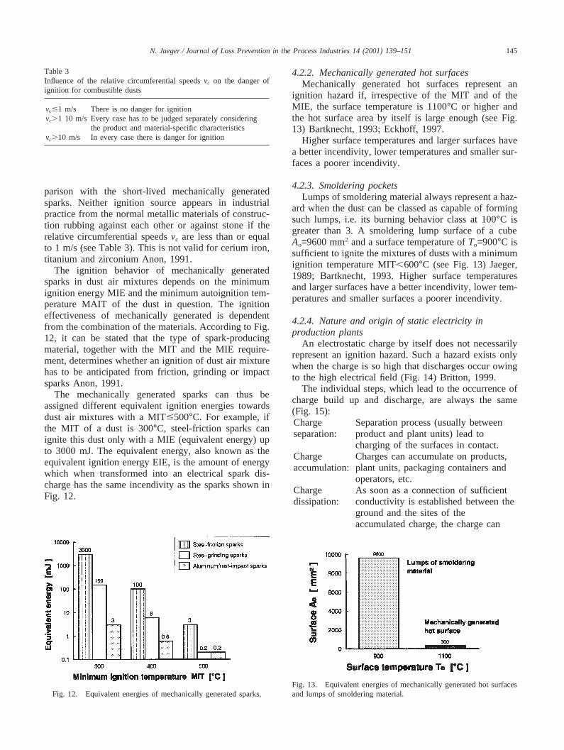
The ignition behavior of mechanically generatedsparks in dust air mixtures depends on the minimumignition energy MIE and the minimum autoignition tem-perature MAIT of the dust in question. The ignitioneffectiveness of mechanically generated is dependentfrom the combination of the materials. According to Fig.12, it can be stated that the type of spark-producingmaterial, together with the MIT and the MIE require-ment, determines whether an ignition of dust air mixturehas to be anticipated from friction, grinding or impactsparks Anon, 1991.
The mechanically generated sparks can thus beassigned different equivalent ignition energies towardsdust air mixtures with a MIT#500°C. For example, ifthe MIT of a dust is 300°C, steel-friction sparks canignite this dust only with a MIE (equivalent energy) upto 3000 mJ. The equivalent energy, also known as theequivalent ignition energy EIE, is the amount of energywhich when transformed into an electrical spark dis-charge has the same incendivity as the sparks shown inFig. 12.
Fig. 12. Equivalent energies of mechanically generated sparks.
4.2.2. Mechanically generated hot surfacesMechanically generated hot surfaces represent an
ignition hazard if, irrespective of the MIT and of theMIE, the surface temperature is 1100°C or higher andthe hot surface area by itself is large enough (see Fig.13) Bartknecht, 1993; Eckhoff, 1997.
Higher surface temperatures and larger surfaces havea better incendivity, lower temperatures and smaller sur-faces a poorer incendivity.
4.2.3. Smoldering pocketsLumps of smoldering material always represent a haz-
ard when the dust can be classed as capable of formingsuch lumps, i.e. its burning behavior class at 100°C isgreater than 3. A smoldering lump surface of a cubeAo=9600 mm2 and a surface temperature ofTo=900°C issufficient to ignite the mixtures of dusts with a minimumignition temperature MIT,600°C (see Fig. 13) Jaeger,1989; Bartknecht, 1993. Higher surface temperaturesand larger surfaces have a better incendivity, lower tem-peratures and smaller surfaces a poorer incendivity.
4.2.4. Nature and origin of static electricity inproduction plants
An electrostatic charge by itself does not necessarilyrepresent an ignition hazard. Such a hazard exists onlywhen the charge is so high that discharges occur owingto the high electrical field (Fig. 14) Britton, 1999.
The individual steps, which lead to the occurrence ofcharge build up and discharge, are always the same(Fig. 15):Charge Separation process (usually betweenseparation: product and plant units) lead to
charging of the surfaces in contact.Charge Charges can accumulate on products,accumulation: plant units, packaging containers and
operators, etc.Charge As soon as a connection of sufficientdissipation: conductivity is established between the
ground and the sites of theaccumulated charge, the charge can
Fig. 13. Equivalent energies of mechanically generated hot surfacesand lumps of smoldering material.
146 N. Jaeger / Journal of Loss Prevention in the Process Industries 14 (2001) 139–151
Fig. 14. Charge accumulation ISSA, 1996.
Fig. 15. Basic scheme of electrostatics ISSA, 1996.
dissipate to the ground.Discharge: If the charge continues to accumulate
because the charges formed processesan not flow to ground quickly enough,a discharge will occur when thebreakdown field strength is reached.
In a powder handling production plant, static chargescan occur at the surface of solids and powdery sub-stances. At this point, it is important to make a distinc-tion between conductors of electricity (e.g. metals) andnon-conductors or insulators (e.g. plastics). Electricallycharged particles (electrons) can move freely on a con-ductor, whereas on an insulator they arc fixed in oneplace. If a substance has excess or a deficiency ofcharged particles, it is said to be charged.
If two uncharged (neutral) objects, of which at leastone is an insulator, are brought into close contact witheach other and then rapidly separated, both of the objectsbecome charged. This occurs because charged particleswill first of all pass from one object to the other butthen, during separation, can not return fast enough.
An electrostatic discharge can be incentive when theenergy released is equal to or greater than the minimumignition energy (see Section 4.1.4 for definition) of amixture. The energy released depends, among otherthings, on the type of discharge. This in turn depends onthe geometry and material of the participating surfaces aswell as on certain other conditions. Table 4 summarizesthe ignition behavior of several types of electrostatic dis-charges.
5. Protective measures
When combustible dusts are handled,avoiding anexplosive atmosphereby keeping the dust concentration
a For brush discharge incendivity it is assumed that dusts are notignitable from a brush discharge. The initial assumption that a dustcannot be ignited from a brush discharge is justified by considerableindustrial experience with handling powders with low MIEs and exten-sive laboratory testing.
b Estimated vale of conical pile discharge incendivity from Glorand Maurer (1993).
147N. Jaeger / Journal of Loss Prevention in the Process Industries 14 (2001) 139–151
outside the explosive range is rarely possible due to sedi-mentation or whirling up of the material being handled.Thus, as a matter of principle, an explosive atmospherecan only be avoided with certainty by reducing the oxy-gen concentration, e.g. inerting. In practice, however, thepossibilities to apply inerting are also limited. For suchsituations, avoidance of effective ignition sources and/orexplosion-proof design are the only measures available.
In the following, protective measures are outlined fortypical powder handling operations in the blendingfacility. As previously stated, the following product andplant properties are important for an accurate hazardassessment:
O Minimum ignition energy, MIE, of the bulk material(measured without inductance in the dischargecircuit),
O Minimum Autoignition Temperature, MAIT, of thebulk material,
O Volume resistivityrR of the powder,O Particle size distribution of the bulk material and
mean value,M,O Volume and shape of the silo or container (volume
and shape of the product heap and of the dust cloud).
Unless otherwise stated, the following sections are basedon the assumption that the bulk materials are handledwithout flammable gases or vapors being present.
5.1. Pneumatic conveying system
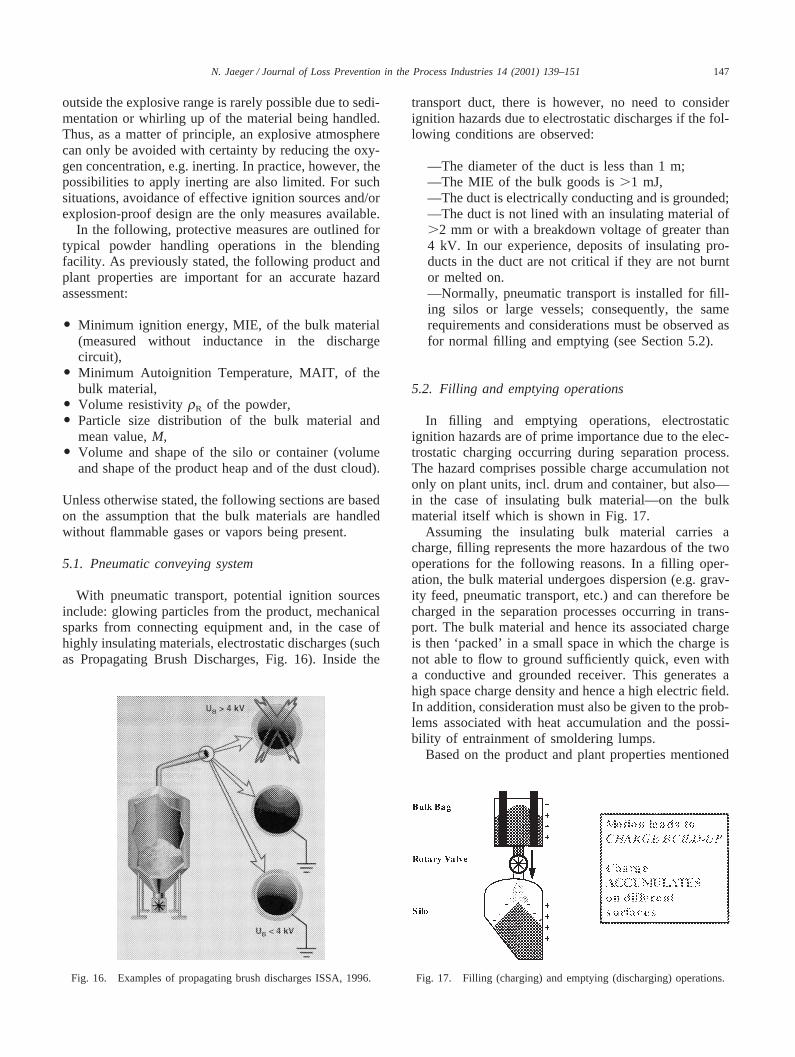
With pneumatic transport, potential ignition sourcesinclude: glowing particles from the product, mechanicalsparks from connecting equipment and, in the case ofhighly insulating materials, electrostatic discharges (suchas Propagating Brush Discharges, Fig. 16). Inside the
Fig. 16. Examples of propagating brush discharges ISSA, 1996.
transport duct, there is however, no need to considerignition hazards due to electrostatic discharges if the fol-lowing conditions are observed:
—The diameter of the duct is less than 1 m;—The MIE of the bulk goods is.1 mJ,—The duct is electrically conducting and is grounded;—The duct is not lined with an insulating material of.2 mm or with a breakdown voltage of greater than4 kV. In our experience, deposits of insulating pro-ducts in the duct are not critical if they are not burntor melted on.—Normally, pneumatic transport is installed for fill-ing silos or large vessels; consequently, the samerequirements and considerations must be observed asfor normal filling and emptying (see Section 5.2).
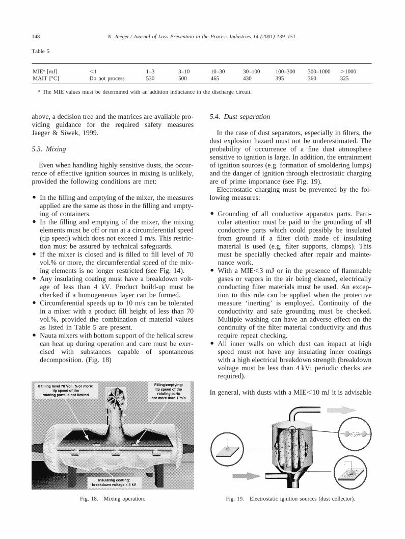
5.2. Filling and emptying operations
In filling and emptying operations, electrostaticignition hazards are of prime importance due to the elec-trostatic charging occurring during separation process.The hazard comprises possible charge accumulation notonly on plant units, incl. drum and container, but also—in the case of insulating bulk material—on the bulkmaterial itself which is shown in Fig. 17.
Assuming the insulating bulk material carries acharge, filling represents the more hazardous of the twooperations for the following reasons. In a filling oper-ation, the bulk material undergoes dispersion (e.g. grav-ity feed, pneumatic transport, etc.) and can therefore becharged in the separation processes occurring in trans-port. The bulk material and hence its associated chargeis then ‘packed’ in a small space in which the charge isnot able to flow to ground sufficiently quick, even witha conductive and grounded receiver. This generates ahigh space charge density and hence a high electric field.In addition, consideration must also be given to the prob-lems associated with heat accumulation and the possi-bility of entrainment of smoldering lumps.
Based on the product and plant properties mentioned
Fig. 17. Filling (charging) and emptying (discharging) operations.
148 N. Jaeger / Journal of Loss Prevention in the Process Industries 14 (2001) 139–151
Table 5
MIEa [mJ] ,1 1–3 3–10 10–30 30–100 100–300 300–1000.1000MAIT [ °C] Do not process 530 500 465 430 395 360 325
a The MIE values must be determined with an addition inductance in the discharge circuit.
above, a decision tree and the matrices are available pro-viding guidance for the required safety measuresJaeger & Siwek, 1999.
5.3. Mixing
Even when handling highly sensitive dusts, the occur-rence of effective ignition sources in mixing is unlikely,provided the following conditions are met:
O In the filling and emptying of the mixer, the measuresapplied are the same as those in the filling and empty-ing of containers.
O In the filling and emptying of the mixer, the mixingelements must be off or run at a circumferential speed(tip speed) which does not exceed 1 m/s. This restric-tion must be assured by technical safeguards.
O If the mixer is closed and is filled to fill level of 70vol.% or more, the circumferential speed of the mix-ing elements is no longer restricted (see Fig. 14).
O Any insulating coating must have a breakdown volt-age of less than 4 kV. Product build-up must bechecked if a homogeneous layer can be formed.
O Circumferential speeds up to 10 m/s can be toleratedin a mixer with a product fill height of less than 70vol.%, provided the combination of material valuesas listed in Table 5 are present.
O Nauta mixers with bottom support of the helical screwcan heat up during operation and care must be exer-cised with substances capable of spontaneousdecomposition. (Fig. 18)
Fig. 18. Mixing operation.
5.4. Dust separation
In the case of dust separators, especially in filters, thedust explosion hazard must not be underestimated. Theprobability of occurrence of a fine dust atmospheresensitive to ignition is large. In addition, the entrainmentof ignition sources (e.g. formation of smoldering lumps)and the danger of ignition through electrostatic chargingare of prime importance (see Fig. 19).
Electrostatic charging must be prevented by the fol-lowing measures:
O Grounding of all conductive apparatus parts. Parti-cular attention must be paid to the grounding of allconductive parts which could possibly be insulatedfrom ground if a filter cloth made of insulatingmaterial is used (e.g. filter supports, clamps). Thismust be specially checked after repair and mainte-nance work.
O With a MIE,3 mJ or in the presence of flammablegases or vapors in the air being cleaned, electricallyconducting filter materials must be used. An excep-tion to this rule can be applied when the protectivemeasure ‘inerting’ is employed. Continuity of theconductivity and safe grounding must be checked.Multiple washing can have an adverse effect on thecontinuity of the filter material conductivity and thusrequire repeat checking.
O All inner walls on which dust can impact at highspeed must not have any insulating inner coatingswith a high electrical breakdown strength (breakdownvoltage must be less than 4 kV; periodic checks arerequired).
In general, with dusts with a MIE,10 mJ it is advisable
149N. Jaeger / Journal of Loss Prevention in the Process Industries 14 (2001) 139–151
Table 6
Environment bulk No explosible Explosible dust Flammablematerial atmosphere atmosphere gases or vapors
MIEa.1 J A B C3 mJ,MIEa,1 J B B CMIEa,3 mJ C C C
a MIE measured without inductance in the electrical circuit.
to implement explosion protection measures which gobeyond the avoidance of effective ignition sources or toconsult the responsible specialist departments. It shouldfurther be noted that the fan must be installed on theclean airside of the filter and that dust deposits must beavoided in the pipe and fan housing (periodic check orinstall a dust control unit).
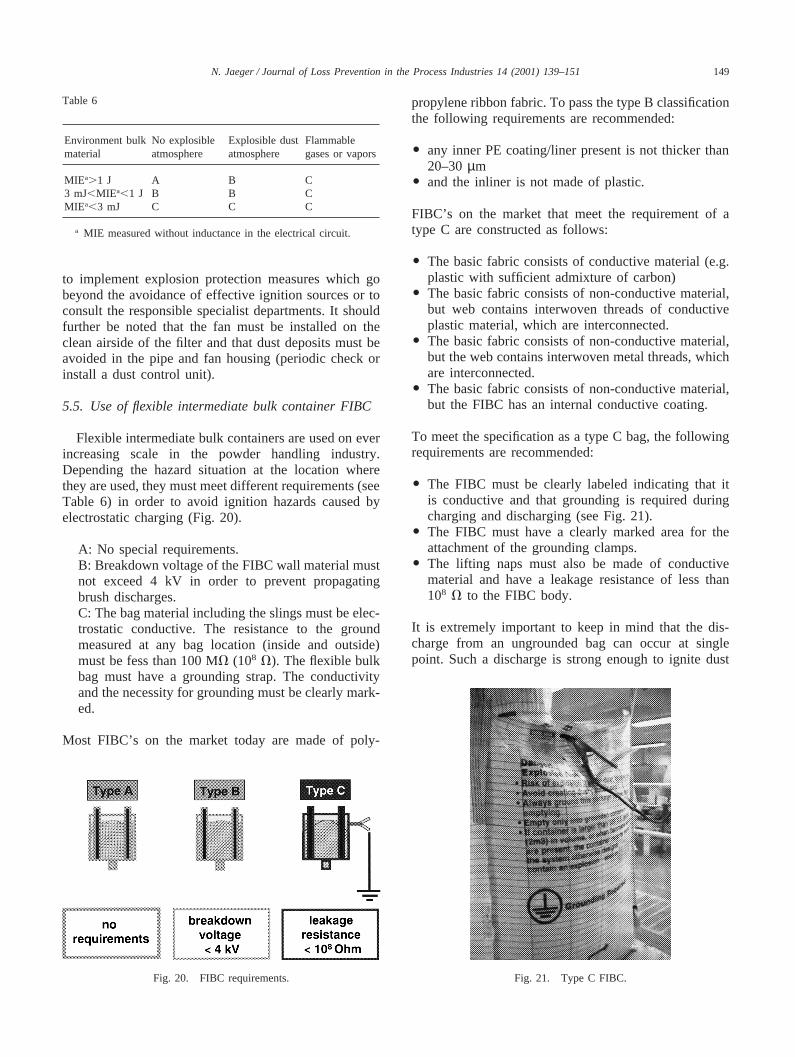
5.5. Use of flexible intermediate bulk container FIBC
Flexible intermediate bulk containers are used on everincreasing scale in the powder handling industry.Depending the hazard situation at the location wherethey are used, they must meet different requirements (seeTable 6) in order to avoid ignition hazards caused byelectrostatic charging (Fig. 20).
A: No special requirements.B: Breakdown voltage of the FIBC wall material mustnot exceed 4 kV in order to prevent propagatingbrush discharges.C: The bag material including the slings must be elec-trostatic conductive. The resistance to the groundmeasured at any bag location (inside and outside)must be fess than 100 MV (108 V). The flexible bulkbag must have a grounding strap. The conductivityand the necessity for grounding must be clearly mark-ed.
Most FIBC’s on the market today are made of poly-
Fig. 20. FIBC requirements.
propylene ribbon fabric. To pass the type B classificationthe following requirements are recommended:
O any inner PE coating/liner present is not thicker than20–30µm
O and the inliner is not made of plastic.
FIBC’s on the market that meet the requirement of atype C are constructed as follows:
O The basic fabric consists of conductive material (e.g.plastic with sufficient admixture of carbon)
O The basic fabric consists of non-conductive material,but web contains interwoven threads of conductiveplastic material, which are interconnected.
O The basic fabric consists of non-conductive material,but the web contains interwoven metal threads, whichare interconnected.
O The basic fabric consists of non-conductive material,but the FIBC has an internal conductive coating.
To meet the specification as a type C bag, the followingrequirements are recommended:
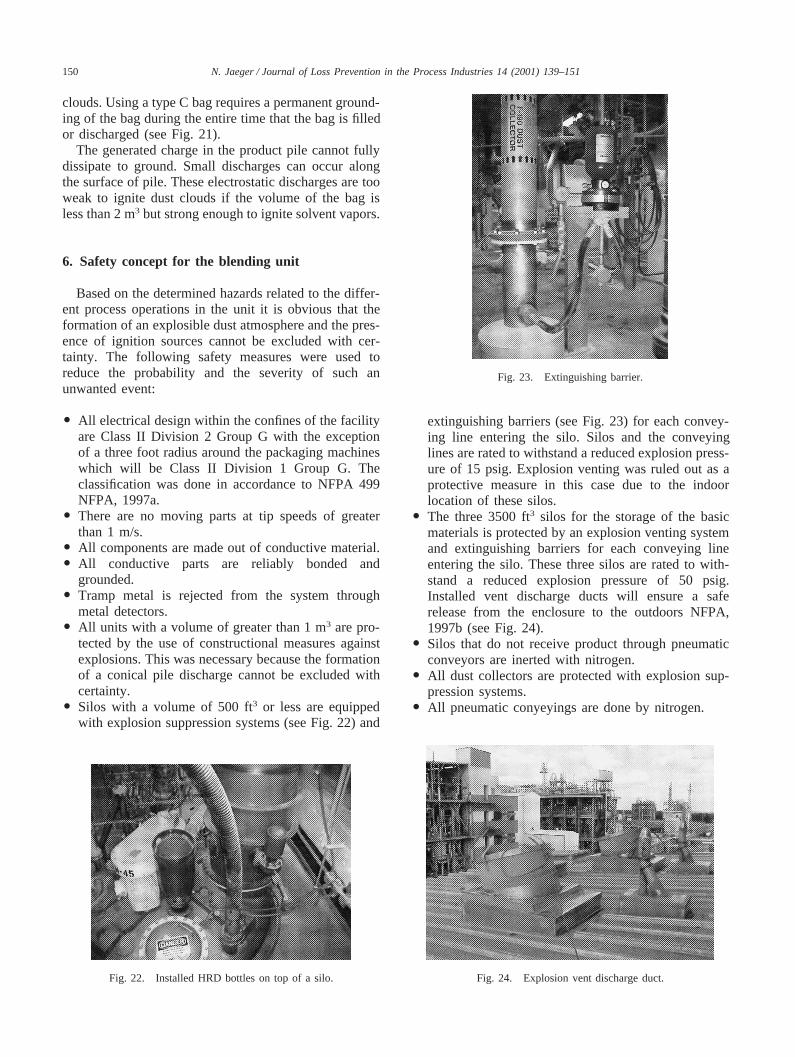
O The FIBC must be clearly labeled indicating that itis conductive and that grounding is required duringcharging and discharging (see Fig. 21).
O The FIBC must have a clearly marked area for theattachment of the grounding clamps.
O The lifting naps must also be made of conductivematerial and have a leakage resistance of less than108 V to the FIBC body.
It is extremely important to keep in mind that the dis-charge from an ungrounded bag can occur at singlepoint. Such a discharge is strong enough to ignite dust
Fig. 21. Type C FIBC.
150 N. Jaeger / Journal of Loss Prevention in the Process Industries 14 (2001) 139–151
clouds. Using a type C bag requires a permanent ground-ing of the bag during the entire time that the bag is filledor discharged (see Fig. 21).
The generated charge in the product pile cannot fullydissipate to ground. Small discharges can occur alongthe surface of pile. These electrostatic discharges are tooweak to ignite dust clouds if the volume of the bag isless than 2 m3 but strong enough to ignite solvent vapors.
6. Safety concept for the blending unit
Based on the determined hazards related to the differ-ent process operations in the unit it is obvious that theformation of an explosible dust atmosphere and the pres-ence of ignition sources cannot be excluded with cer-tainty. The following safety measures were used toreduce the probability and the severity of such anunwanted event:
O All electrical design within the confines of the facilityare Class II Division 2 Group G with the exceptionof a three foot radius around the packaging machineswhich will be Class II Division 1 Group G. Theclassification was done in accordance to NFPA 499NFPA, 1997a.
O There are no moving parts at tip speeds of greaterthan 1 m/s.
O All components are made out of conductive material.O All conductive parts are reliably bonded and
grounded.O Tramp metal is rejected from the system through
metal detectors.O All units with a volume of greater than 1 m3 are pro-
tected by the use of constructional measures againstexplosions. This was necessary because the formationof a conical pile discharge cannot be excluded withcertainty.
O Silos with a volume of 500 ft3 or less are equippedwith explosion suppression systems (see Fig. 22) and
Fig. 22. Installed HRD bottles on top of a silo.
Fig. 23. Extinguishing barrier.
extinguishing barriers (see Fig. 23) for each convey-ing line entering the silo. Silos and the conveyinglines are rated to withstand a reduced explosion press-ure of 15 psig. Explosion venting was ruled out as aprotective measure in this case due to the indoorlocation of these silos.
O The three 3500 ft3 silos for the storage of the basicmaterials is protected by an explosion venting systemand extinguishing barriers for each conveying lineentering the silo. These three silos are rated to with-stand a reduced explosion pressure of 50 psig.Installed vent discharge ducts will ensure a saferelease from the enclosure to the outdoors NFPA,1997b (see Fig. 24).
O Silos that do not receive product through pneumaticconveyors are inerted with nitrogen.
O All dust collectors are protected with explosion sup-pression systems.
O All pneumatic conyeyings are done by nitrogen.
Fig. 24. Explosion vent discharge duct.
151N. Jaeger / Journal of Loss Prevention in the Process Industries 14 (2001) 139–151
References
Anon (1991).Perry’s chemical engineers’ handbook.(7th ed). NewYork: McGraw-Hill.
ASTM 2019-99 (1999).Standard test method for minimum ignitionenergy of a dust cloud in air.
Bartknecht, W. (1993).Explosion protection, basics and application(in German).Berlin: Springer-Verlag.
Britton, L. G. (1999).Avoiding static ignition hazards in chemicaloperations.CCPS.
CCPS (1995).Guidelines for process safety documentation, ch. 6, Pro-cess hazard analysis.
Information C-2.Guide to risk analysis, Ciba-Geigy internal Infor-mation, September.
Eckhoff, R. K. (1997).Dust explosions in the process industries.(2nded). Oxford: Butterworth-Heinemann.
Glor, M., & Maurer, B. (1993). Ignition tests with discharges frombulked polymeric granules in silos.J. Electrostatic, 30, 123–134.
ISSA (1996). Static electricity-ignition hazards and protection meas-ures. Heidelberg, Germany.
Jaeger, N. (1989).Zuendwirksamkeit von Glimmnestern in Staub/LuftGemischen.Dusseldorf: VDI Bericht.
Jaeger, N., & Siwek, R. (1999). Prevent explosions of combustibledusts.Chemical Engineering Progress, AIChE, June.
Luettgens, G., & Glor, M. (1989).Understanding and controllingstatic electricity.Ehingen, Germany: Expert Verlag.
NFPA (1993). NFPA 77, Static electricity.NFPA (1997a). NFPA 499, Recommendation for the classification of
combustible dusts and of hazardous (classified) locations for elec-trical installations in chemical process areas.
NFPA (1997b). NFPA 69, Standard on explosion prevention systems.NFPA (1998). NFPA 650, Standard for pneumatic conveying systems
for handling combustible particulate solids.NFPA (1997c). NFPA 654, Standard for the prevention of fire and
dust explosions from the manufacturing, processing and handlingof combustible particulate solids.
Norbert Jaeger is production manager optical brighteners with Ciba Spe-cialty Chemicals, Grenzach, Germany. From 1994 until 2000 he wasworking for Ciba’s NAFTA Central Safety Testing Laboratory, where hewas responsible for explosion technology and static electricity prevention.He joined Ciba in 1987 as a member of its Corporate Safety and Environ-ment unit in Basle, Switzerland. From 1988 through 1994, he was thesafety and loss prevention manager for Ciba’s additives production site inLampertheim, Germany. Jaeger holds an MS in safety science from theUniversitiy of Wuppertal, Germany. He is a member of ASTM CommitteeE-27 on Hazard Potential of Chemicals, Subcommittee 05, Explosivityand Ignitibility of Dust Clouds, a member of AIChE‘s Center for ChemicalProcess Safety’s reactive chemicals subcommittee, and a member of theworking group on dust explosions of the International Social SecurityAssociation.

![Index [ftp.feq.ufu.br]ftp.feq.ufu.br/.../Double/fire_handbook/14298_indx.pdf · BLEVE (Boiling Liquid Expanding Vapor Explosion) 224 Block off Operations 197 Boiler Compound, Liquid](https://static.documents.pub/doc/80x56/5ea2589dad656856d47e9db5/index-ftpfequfubrftpfequfubrdoublefirehandbook14298indxpdf-bleve.jpg)


