13


2
SAFRAIL™ Industrial Fiberglass Handrail Systems
SAFRAIL™ industrial fiberglass handrails are commercial railing systems for stair rails, platform/walkway handrails and guardrails. SAFRAIL™ systems are fabricated from pultruded fiberglass components produced by Strongwell and molded thermoplastic connectors. The railing systems are particularly well-suited to corrosive environments like those found in industrial, chemical and wastewater treatment plants as well as commercial structures with urban and salt air corrosion.
SAFRAIL™ fiberglass handrail systems are:• Corrosion resistant • Easy to field fabricate• Structurally strong • Low in thermal conductivity• Impact resistant • Low electrical conductivity• Lightweight
SAFRAIL™ systems are the result of more than 40 years of experience in the manufacture, design and fabrication of fiberglass handrail systems. The systems offer the following advantages:• Ease of Assembly — SAFRAIL™ systems are produced in lightweight
standard sections that include both post and rail. Systems can be prefabricated in large sections and shipped to the site or they can also be fabricated and installed on site with simple carpenter tools.
• Internal Connection System — All connections fit flush, resulting in a pleasing, streamlined appearance. The internal connections allow the construction of continuous handrail systems around circular tanks without special fittings.
• Safety Features — SAFRAIL™ systems come in a “safety yellow color”, feature low electrical conductivity for worker safety and exhibit high strength. Systems meet federal OSHA standards with a 2:1 factor of safety with a 6-foot (1830mm) maximum post spacing. SAFRAIL™ systems also comply with international standard AFNOR NF E 85-101.
• Low Maintenance — Corrosion resistant fiberglass with molded-in color will outlast aluminum or steel systems with virtually no maintenance.
StrongwellrecommendsanoptionalpolyurethanecoatingtoensureprolongedyearsofcolorstabilityinUVintensiveenvironments.
• Cost Effective — Fiberglass components and easy-to-assemble design provide savings on labor and maintenance, resulting in long-term savings and elimination of the cost and inconvenience of “downtime for repairs” in plant operations.
GuardrailSAFRAIL™ industrial systems can be used in guardrail applications where railing is needed to protect the open side of an elevated walkway. SAFRAIL™ systems meet OSHA standards for a height of 42" (1067mm) from the top of walkway to the top of the guardrail with a 2:1 factor of safety. The OSHA loading requirement for both guardrail and handrail is a 200 pound (890 N) concentrated load at any point or direction on the top rail. Other building codes may require different loading conditions.
SAFRAIL™ system in a chemical plant.
Internal connections make circular handrail systems such as these possible around tanks.
SAFRAIL™ ladder and cage systems, also available from Strongwell, are an ideal accompaniment to Strongwell's handrail systems when additional access is needed.
SAFRAIL™ and DURAGRID® pultruded grating were fabricated to make access platforms over waste water recycling tanks. The previous steel structure corroded, and was unsafe.

3
Materials of Construction
SAFRAIL™ is an engineered composite consisting of:
• Continuous glass fibers • Two continuous strand glass mats • A synthetic surfacing veil • Fire-retardant polyester resin
This unique combination provides the ultimate in strength, stiffness and long-term corrosion and UV protection.
R .145"
WA
LL
2" S
QU
AR
E
0.15
6"(4
.0m
m)
(50.
8mm
)
(3.7mm)
A = 1.151 in.2 (742.5mm2)S = 0.657 in.3 (1.077 x 104 mm3)I = 0.657 in.4 (2.735 x 105 mm4)E = 3.7 x 10⁶ psi (2.55 x 10¹⁰ N/m2)WT = 0.95 lbs./lin.ft. (431 Grams)where E = Flexural modulus full section
Square Post or Rail Section Properties
Properties Test Method Square Rail Values
Tensile Stress ASTM D638 30,000 psi (207N/mm2)Tensile Modulus ASTM D638 2.5x10⁶ psi (17.2x10³ N/mm2)Compressive Stress ASTM D695 30,000 psi (207N/mm2)Compressive Modulus ASTM D695 2.5x10⁶ psi (17.2x10³ N/mm2)Flexural Stress ASTM D790 30,000 psi (207N/mm2)Flexural Modulus ASTM D790 1.6x10⁶ psi (11.0x10³ N/mm2)Shear Stress ASTM D2344 4,500 psi (31N/mm2)Density ASTM D792 0.060-0.070 lbs/in3 (1.72-1.94x10⁻³ g/mm3)24 Hr. Water Absorption ASTM D570 0.6% maxCoef. Thermal Expansion ASTM D696 4.4x10⁻⁶ in/in/°F (min.) (14.5x10⁻⁶mm/mm/Co)Flexural Stress Full Section 36,000 psi (typical) (248N/mm2)Flexural Modulus Full Section 3.7x10⁶ psi (typical) (25.5x103x103 N/mm2)
Minimum Mechanical Properties for Pultruded Rail and Post
30,000 psi (207N/mm2)2.5x106 psi (17.2x10³ N/mm2)30,000 psi (207N/mm2)2.5x106 psi (17.2x10³ N/mm2)30,000 psi (207 N/mm2)1.6x106 psi (11.0x10³ N/mm2)4,500 psi (31N/mm2)0.060-0.070 lbs/in3 (1.72-1.94x10⁻³ g/mm3)0.6% max 4.4x10⁻⁶ in/in/°F (min.) (14.5x10⁻⁶ mm/mm/CO)60,000 psi (typical) (414N/mm2)4.5x106 psi (typical) (31.0x10³ N/mm2)
Round Post or Rail Section Properties
A = 1.05 in.2 (677.4mm2)S = 0.405 in.3 (6.637 x 103 mm3)I = 0.385 in.4 (1.602 x 105 mm4)E = 4.5 x 10⁶ psi (3.10 x 10¹⁰ N/m2)WT = 0.86 lbs./lin. ft. (380 grams)where E = Flexural modulus full section
Ø 1.51”(38.3mm)
Ø 1.90”(48.3mm)
Round Rail Values
4
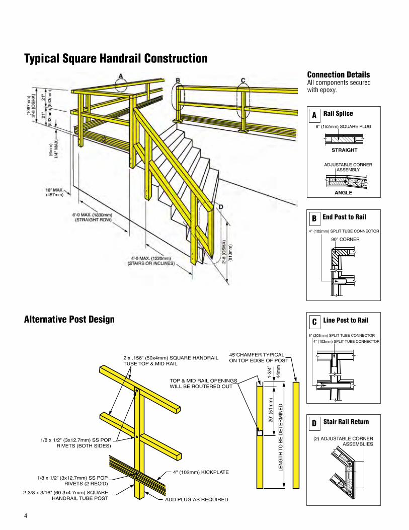
Typical Square Handrail ConstructionConnection DetailsAll components secured with epoxy.
Alternative Post Design
2 x .156" (50x4mm) SQUARE HANDRAIL TUBE TOP & MID RAIL
1/8 x 1/2" (3x12.7mm) SS POP RIVETS (BOTH SIDES)
2-3/8 x 3/16" (60.3x4.7mm) SQUARE HANDRAIL TUBE POST
1/8 x 1/2” (3x12.7mm) SS POP RIVETS (2 REQ'D)
ADD PLUG AS REQUIRED
4" (102mm) KICKPLATE
TOP & MID RAIL OPENINGS WILL BE ROUTERED OUT
20” (
51m
m)
LEN
GTH
TO
BE
DE
TER
MIN
ED
1-3/
4”
45 CHAMFER TYPICAL ON TOP EDGE OF POST
°
44m
m
Stair Rail Return
(2) ADJUSTABLE CORNERASSEMBLIES
D
Line Post to Rail
8" (203mm) SPLIT TUBE CONNECTOR
4" (102mm) SPLIT TUBE CONNECTOR
C
End Post to Rail
4" (102mm) SPLIT TUBE CONNECTOR
90° CORNER
B
6" (152mm) SQUARE PLUG
STRAIGHT
ANGLE
ADJUSTABLE CORNER ASSEMBLY
Rail SpliceA(106
7mm
)
(533
mm
)(6
mm
)
(457mm)
(813
mm
)
(533
mm
)

5
Suggested Square Post and Kick Plate Installation
WELD (STEEL)
(1) 6" (152mm) SQUARE PLUG (TYPICAL)
6" PLUG
4" M
IN
(152mm) (1
02m
m)
6" PLUG
4" M
IN
WELD
STOP
1/16" (1.6mm) MAX CLEARANCE BETWEEN POST & SLEEVE
(152mm)
(102
mm
)
1/8” x 1/2” (3x12.7mm) SS POP RIVETS
CUT 1-1/2" x 1-1/2" x 4" (38x38x102mm)ANGLE FROM 2 x 2 TUBE
CUT (2) 3/4"x 3" (20x76mm) STRIPS FROM 2 x 2 TUBE OR KICKPLATE
1/8” x 1/2” (3x12.7mm)SS POP RIVETS
Posts with FRPBase Plate
Fastening to Structural Steel or Fiberglass
I BEAM WITH SPACERS
PERPENDICULAR PLATE
PARALLELPLATE
CHANNEL
ANCHOREDTO CONCRETE
EMBEDDEDIN CONCRETE
SLEEVE ONSTRUCTURAL STEEL
SLEEVE INCONCRETE
Kickplateto Post
KickplateCorner
KickplateSplice
Fastening to Concrete Removable Posts
Square Handrail Components
R .145"
WA
LL
2" S
QU
AR
E
0.15
6"(4
.0m
m)
(50.
8mm
)
(3.7mm) 1.01" (25.7mm) THRU
1.68
" (4
3mm
)S
QU
AR
E
.14” WALL(3.6mm)
1.70
"(4
3mm
)
2"
CU
BE
2.
5"
LEG
S
1.68
" S
QU
AR
E
(63.
5mm
) (5
0mm
)
(43m
m)
1.68" (43mm)SQUARE
30°MIN.
1/4" (6mm) PIN
4.9" (124mm)
2" SQUARE
1/8"
3/
4"
(50mm)
(19m
m) (
3.18
mm
)
Post or Rail Kickplate
90o Corner Adjustable Corner Assembly
Post Base End Cap
(Mounted To Post)
Note: For CappingTubes (Special Construction)
9/16"
4"
6" (152mm)
.75"
2"
1"
4"
2" x 2" (50x50mm) MOUNTED IN CENTER OF BASE PLATE
(25mm)
(102mm)
(102
mm
)
(14mm) (2
0mm
)
(50m
m)
Square Plug Split Tube Connector
.50"
.125" WALL
4.0
0"
or
6.0
0"
(102m
m o
r 152m
m)
(3.18mm)
(12.7mm)
6" also available.
6
(106
7mm
)
(533
mm
) (53
3mm
)
(6m
m)
(457mm)
(1524mm)
(1220mm)
(813
mm
)
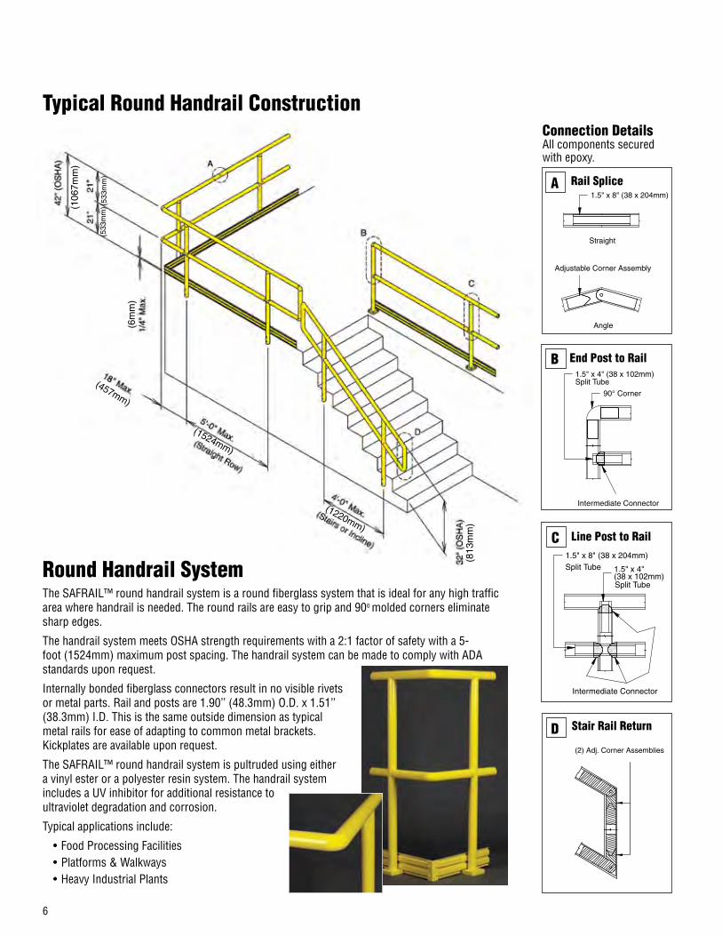
1.5" x 8" (38 x 204mm)
Straight
Angle
Adjustable Corner Assembly
Rail SpliceA
90° Corner
1.5" x 4" (38 x 102mm)Split Tube
Intermediate Connector
End Post to RailB
Intermediate Connector
1.5" x 4"(38 x 102mm)
1.5" x 8" (38 x 204mm)Split Tube
Split Tube
Line Post to RailC
(2) Adj. Corner Assemblies
Stair Rail ReturnD
Round Handrail SystemThe SAFRAIL™ round handrail system is a round fiberglass system that is ideal for any high traffic area where handrail is needed. The round rails are easy to grip and 90o molded corners eliminate sharp edges.
The handrail system meets OSHA strength requirements with a 2:1 factor of safety with a 5-foot (1524mm) maximum post spacing. The handrail system can be made to comply with ADA standards upon request.
Internally bonded fiberglass connectors result in no visible rivets or metal parts. Rail and posts are 1.90’’ (48.3mm) O.D. x 1.51’’ (38.3mm) I.D. This is the same outside dimension as typical metal rails for ease of adapting to common metal brackets. Kickplates are available upon request.
The SAFRAIL™ round handrail system is pultruded using either a vinyl ester or a polyester resin system. The handrail system includes a UV inhibitor for additional resistance to ultraviolet degradation and corrosion.
Typical applications include:
• Food Processing Facilities• Platforms & Walkways• Heavy Industrial Plants
Connection DetailsAll components secured with epoxy.
Typical Round Handrail Construction

7
Round Handrail Components
.50"
.125" WALL
4.0
0"
or
6.0
0"
(102m
m o
r 152m
m)
(3.18mm)
(12.7mm)
90o Corner Adjustable Corner Assembly
(Mounted To Post)
Note: For Capping Tubes (Special Construction)
Round Plug Split Tube Connector
1.90" (48.3mm) OD.
1.51" (38.3mm) ID.
1.5" (38mm) OD.
1" (25mm) ID.
1.5"
2.5" (64mm)
(38mm)
1.9" (48.3mm)
3/4"
(2
0mm
)
4" (102mm)
.75" (20mm)
5.7"
30° Min.
1.5"
(145mm)
(38m
m)
Suggested Round Post and Kick Plate Installation
I BEAM WITH SPACERS
PERPENDICULAR PLATE
PARALLELPLATE
CHANNEL
ANCHOREDTO CONCRETE
EMBEDDEDIN CONCRETE
SLEEVE ONSTRUCTURAL STEEL
SLEEVE INCONCRETE
Kickplateto Post
KickplateCorner
KickplateSplice
Fastening to Concrete Removable Posts
1.25" (32mm) ID.
1.5" (38mm) OD.
End CapPost Base
(Mounted To Post)
KickplateIntermediate Connector
6" also available.
Posts with FRPBase Plate
Fastening to Structural Steel or Fiberglass
S.S. KickplateBracket
O 1/4" (6mm) Bolts/
O 1.5 (38mm) TubeTypical/
2" M
in.
2" M
in.
2" M
in.
2" M
in.
Weld(Stl.)
4" M
in.
4" M
in.
4" M
in.
Weld
1/8" x 1/2" (3.2 x 12.7mm) SS Pop Rivets
Cut 1-1/2" x 1-1/2" x 4" (38 x 38 x 102mm) Angle From 2 x 2 (50 x 50mm) Tube
1/8" x 1/2" (3.2 x 12.7mm) SS Pop
Rivets
Cut 3/4" x 3" (20 x 76mm) Strips From 2 x 2 (50 x 50mm) Tube
(50m
m)
(50m
m)
(50m
m)
(50m
m)
(102
mm
)
(102
mm
)
(102
mm
)
2" M
in.
2" M
in.
2" M
in.
2" M
in.
(50m
m)
(50m
m)
(50m
m)
(50m
m)

8
SAFRAIL™ Channel Top Handrail System
SAFRAIL™ channel top industrial fiberglass handrail is an economical commercial railing system designed for long runs on platforms and walkways. The railing system is designed for fabrication efficiency and is not particularly well-suited for stair rails with twists and turns. SAFRAIL™ channel top can be used in combination with round and square SAFRAIL™ as needed.
SAFRAIL™ channel top systems are fabricated as handrails and guardrails using pultruded fiberglass components produced by Strongwell and molded thermoplastic connectors.
SAFRAIL™ channel top system consists of a 2.50" x 2.38" (63.50mm x 60.45mm) channel top rail, 2" x 2" x .156" (50.80mm x 50.80mm x 3.96mm) square tube posts and a 1" inch diameter round tube mid rail.
AdvantagesThe benefits to designing a SAFRAIL™ channel top fiberglass handrail system are:
• Easy installation and field fabrication
• Economical installation of long straight runs
• Fewer components, reducing freight cost
• No epoxy required
• All riveted connections
In addition, SAFRAIL™ channel top shares same benefits and advantages of the original SAFRAIL™ such as:
• Corrosion resistance
• Strength
• Impact resistance
• Light weight
• Low thermal conductivity
• Low electrical conductivity
Standard SAFRAIL™ channel top handrail systems are pultruded using a polyester, fire-retardant resin system. The handrail system includes a UV inhibitor for additional resistance to ultraviolet degradation and corrosion. Standard color is yellow, however, other colors are available upon request.
Safety
The channel top handrail system meets OSHA strength requirements. It has also been independently tested and meets the British Standard EN ISO 14122-3:2001 requirements. The handrail system sustained a falling weighted bag impact force of 216.5 ft-lb (293.6 N-m).

9
A
B
C
D
E
F
G
D
19.7
”19
.7”
(500
mm
)(5
00m
m)43.3
”(1
100m
m)
0.4”
Max
.(1
0mm
)
7.9” Max.(200mm)
59” Max.(1500mm)
(Straight Row)
47.2” Max.(1200mm)(Stairs or Incline)
3.5”
(90m
m)
2.50” x 2.38” Channel(63.50mm x 60.45mm)
Ø 1” Tube(25.4mm)
2” (50.8mm)Square Tube
2.50” x 2.38” Channel(63.50mm x 60.45mm)
Ø 1” Tube(25.4mm)
2” (50.8mm)Square Tube
2.50” x 2.38” Channel(63.50mm x 60.45mm)
Ø 1” Tube(25.4mm)
2” (50.8mm)Square Tube
2.50” x 2.38” Channel(63.50mm x 60.45mm)
Ø 1” Tube(25.4mm)
2” (50.8mm)Square Tube
2.50” x 2.38” Channel(63.50mm x 60.45mm)
Ø 1” Tube(25.4mm)
2” (50.8mm)Square Tube
2.50” x 2.38” Channel(63.50mm x 60.45mm)
Ø 1” Tube(25.4mm)
2” (50.8mm)Square Tube
Rail Splice
End Return
Corner Post
End Post to Rail
Corner End Return
Top & Mid Rail Splice
Typical Details
Typical Channel Top Handrail Construction
Alternative Post Design
Adjustable Top Rail SpliceG
2.50” x 2.38” Channels(63.50mm x 60.45mm)
2” (50.8mm) Square Tubes
Adjustable Corner Assm.
Note: Field epoxy adjustable corner inside 2” (50.8mm) tubes at angled intersections. Slip inside 2.50” (63.50mm) channels.
90o Corner Top Rail SpliceG
2.50” x 2.38” Channels(63.50mm x 60.45mm)
90o Corner Connector
2” (50.8mm) Square Tubes
Note: Field epoxy adjustable corner inside 2” (50.8mm) tubes at angled intersections. Slip inside 2.50” (63.50mm) channels.
A
B
C
D
E
F
10
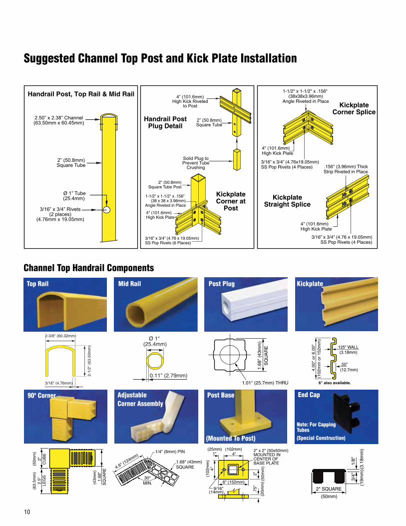
Suggested Channel Top Post and Kick Plate Installation
2.50” x 2.38” Channel(63.50mm x 60.45mm)
Ø 1” Tube(25.4mm)
2” (50.8mm)Square Tube
3/16” x 3/4” Rivets(2 places)
(4.76mm x 19.05mm)
4” (101.6mm)High Kick Riveted
to Post
Solid Plug toPrevent Tube
Crushing
2” (50.8mm)Square Tube
Handrail Post, Top Rail & Mid Rail
Handrail Post Plug Detail
Kickplate Corner Splice
KickplateCorner at
Post
KickplateStraight Splice
1-1/2" x 1-1/2" x .156" (38x38x3.96mm)
Angle Riveted in Place
4" (101.6mm)High Kick Plate
3/16” x 3/4” (4.76x19.05mm)SS Pop Rivets (4 Places)
1-1/2" x 1-1/2" x .156" (38 x 38 x 3.96mm)
Angle Riveted in Place
4" (101.6mm)High Kick Plate
3/16” x 3/4” (4.76 x 19.05mm)SS Pop Rivets (6 Places)
2" (50.8mm)Square Tube Post
.156" (3.96mm) ThickStrip Riveted in Place
4" (101.6mm)High Kick Plate
3/16” x 3/4” (4.76 x 19.05mm)SS Pop Rivets (4 Places)
2-3/8" (60.32mm)
2-1/
2" (
63.5
0mm
)
3/16" (4.76mm)
Ø 1" (25.4mm)
0.11" (2.79mm)
2-3/8" (60.32mm)
2-1/
2" (
63.5
0mm
)
3/16" (4.76mm)
Ø 1" (25.4mm)
0.11" (2.79mm)
2"
CU
BE
2.
5"
LEG
S
1.68
" S
QU
AR
E
(63.
5mm
) (5
0mm
)
(43m
m)
1.68" (43mm)SQUARE
30°MIN.
1/4" (6mm) PIN
4.9" (124mm)
2" SQUARE
1/8"
3/
4"
(50mm)
(19m
m) (
3.18
mm
)
90o Corner Adjustable Corner Assembly
Post Base End Cap
(Mounted To Post)
Note: For CappingTubes (Special Construction)
9/16"
4"
6" (152mm)
.75"
2"
1"
4"
2" x 2" (50x50mm) MOUNTED IN CENTER OF BASE PLATE
(25mm)
(102mm)
(102
mm
)
(14mm) (2
0mm
)
(50m
m)
Mid Rail
.50"
.125" WALL
4.0
0"
or
6.0
0"
(102m
m o
r 152m
m)
(3.18mm)
(12.7mm)
6" also available.
Top Rail
1.01" (25.7mm) THRU
1.68
" (4
3mm
)S
QU
AR
E
Post Plug Kickplate
Channel Top Handrail Components

11
Handrail System Options
Custom Handrail SystemsSAFRAIL™ systems are designed to fit a wide variety of applications and, because they are standard systems, to be cost effective. However, custom handrail systems are available from Strongwell to suit special needs. Some examples of custom handrail from Strongwell include vertical pickets, two-color handrail, architectural handrail and heavy duty handrail systems.
UV CoatingStrongwell recommends that an industrial grade polyurethane coating be applied to the finished handrail and/or ladder and cage for additional protection against fading in outdoor applications. Standard SAFRAIL™ handrail systems are unpainted; the polyurethane UV coating must be requested when ordered.
Resin SystemsA polyester resin system is standard for SAFRAIL™ handrail systems but other resin systems are available upon request.
ColorsSAFRAIL™ handrail and ladder systems are produced in a standard safety yellow color. Other colors are available upon request.
Strongwell designed this vertical rail system to use less material and, in turn, be more cost effective than conventional horizontal aluminum or fiberglass handrail systems.
More than 70,000 lineal feet of SAFRAIL™ handrail lines the walkways and emergency escape routes of the Chicago Transit Authority’s rail lines. The handrail, along with the DURADEK® grating also supplied by Strongwell, represents one of the largest fiberglass installations in America.
Fiberglass platforms at the Road Division of Franklin County, Ohio use SAFRAIL™ square handrail around tanks that contain de-icing fluids which are extremely corrosive to metal.
SAFRAIL™ handrail is used on walkways and platforms for safe, maintenance-free worker access.
In 2002, Fort Lauderdale, FL received the very first installation of Strongwell’s round SAFRAIL™ on the 17th Street Bridge’s fenders. Inspection in 2010 (shown here) revealed that 8 years of exposure to the Florida sun and the Atlantic Ocean have resulted in no corrosion related issues.


CUSTOM DESIGN AND FABRICATIONRedwood Plastics supplies a wide range of high quality, custom components to solve a variety of problems including; shock, abrasion, noise, wear, & friction. We work with you to develop valuable application solutions to reduce equipment wear, diminish maintenance costs and increase production.
We cannot anticipate all conditions under which this information and our products or the products of other manufacturers in combination with our products may be used. We accept no responsibility for results obtained by the application of this or the safety and suitability of our products, whether alone or in combination with other products. Users are advised to make their own test to determine the safety and suitability of each such product or product combination for their own purposes. Unless otherwise agreed in writing, we sell the products without warranty, and buyers and users assume all responsibility and liability for loss or damage arising from the handling and use of our products, whether used alone or in combination with other products. For most recent technical information, phone 360 225 1491 in USA or 604 607 6000 in Canada.
Call Your Local Representative Today
A Member of
CDN 1 800 667 0999USA 1 866 733 2684


