20 Salamandre ® distribution trunking standards and quality assessment Min. Max. 1. Storage and transport – 25°C – 2. Installation – 15°C – 3. Application – + 60°C ■ Distribution trunking classification Legrand’s steel distribution trunking was previously made to BS 4678 Part 1. This is now an obsolescent standard and has been replaced by the latest BS European standard BS EN 50085-2-1 Classification to BS EN 50085-1 2005 and BS EN 50085-2-1 2006 Clause 6.2 According to resistance to impact for installation and application : impact 2·0J Clause 6.3 According to temperatures given in tables 1, 2 and 3 : Clause 6.4 According to resistance to flame propagation : non-flame propagating (unpainted) Clause 6.5 According to electrical continuity characteristic : CTS with electrical continuity (maximum linear impedance 1·0 milliohms per metre) Clause 6.6 According to electrical insulating characteristic : CTS without electrical insulating characteristic Clause 6.7 According to degree of protection provided by enclosure according to BS EN 60529 : 1991 : IP30 – standard range IP4X – IP range with cover strap Clause 6.9 According to system access cover retention : CTS access cover which can only be opened with a tool Clause 6.10 According to electrically protective separation : CTS without internal protective partition Clause 6.101 According to position when surface mounted : CTS surface mounted on wall CTS surface mounted on ceiling (CTS mounted away from the wall or ceiling using fixing devices Declare cover mounted upwards 2·0 metre hanger centres) Clause 6.103 According to the functions provided : Type 2 CTS (distribution) ■ Quality assessment and trade association memberships Legrand offers a vast range of fully integrated cable management products to meet the demands of today’s commercial and industrial installations... designed and manufactured to the highest standards at our Scarborough and West Bromwich sites Quality and environmental assessment Legrand Electric Limited holds ISO 9001 : 2008 Quality Assessment Registrations from Intertek Systems Certification UK and Bureau Veritas The Salamandre range is manufactured at Legrand sites that are accredited to ISO 14001 : 2004 Environmental Management System Trade association memberships Legrand Electric Limited is a member of the following trade associations : • BEAMA • Galvanizers Association (GA) • Energy Industries Council (EIC) • First Point Assessment (FPAL) Registered Reg no. 10042065
Transcript
20
Salamandre® distribution trunkingstandards and quality assessment
Min. Max.
1. Storage and transport – 25°C –
2. Installation – 15°C –
3. Application – + 60°C
■ Distribution trunking classification
Legrand’s steel distribution trunking was previously made to BS 4678 Part 1. This is now an obsolescent standard and has been replaced by the latest BS European standard BS EN 50085-2-1
Classification to BS EN 50085-1 2005 and BS EN 50085-2-1 2006
Clause 6.2 According to resistance to impact for installation and application : impact 2·0J
Clause 6.3 According to temperatures given in tables 1, 2 and 3 :
Clause 6.4 According to resistance to flame propagation :non-flame propagating (unpainted)
Clause 6.5 According to electrical continuity characteristic : CTS with electrical continuity (maximum linear impedance 1·0 milliohms per metre)
Clause 6.6 According to electrical insulating characteristic :CTS without electrical insulating characteristic
Clause 6.7 According to degree of protection provided by enclosure according to BS EN 60529 : 1991 : IP30 – standard rangeIP4X – IP range with cover strap
Clause 6.9 According to system access cover retention :CTS access cover which can only be opened with a tool
Clause 6.10 According to electrically protective separation :CTS without internal protective partition
Clause 6.101 According to position when surface mounted :CTS surface mounted on wallCTS surface mounted on ceiling(CTS mounted away from the wall or ceiling using fixing devicesDeclare cover mounted upwards 2·0 metre hanger centres)
Clause 6.103 According to the functions provided :Type 2 CTS (distribution)
■ Quality assessment and trade association memberships
Legrand offers a vast range of fully integrated cable management products to meet the demands of today’s commercial and industrial installations... designed and manufactured to the highest standards at our Scarborough and West Bromwich sites
Quality and environmental assessment
Legrand Electric Limited holds ISO 9001 : 2008 Quality Assessment Registrations from Intertek Systems Certification UK and Bureau Veritas
The Salamandre range is manufactured at Legrand sites that are accredited to ISO 14001 : 2004 Environmental Management System
Trade association memberships
Legrand Electric Limited is a member of the following trade associations :• BEAMA• Galvanizers Association (GA)• Energy Industries Council (EIC)• First Point Assessment (FPAL)
Salamandre® distribution trunking trunking size, capacity and weights
■ Cable trunking capacity guide
For each size of cable, multiply the number to be installed by the common factor. Add together the results of these calculations for all cable sizes. The correct trunking size must have a capacity factor equal to or greater than this total
Minimum trunking size required in this example = 75 x 50 (trunking capacity factor 1 555)
Size (mm) Trunking capacity factor
50 x 50 1 037
75 x 50 1 555
75 x 75 2 371
100 x 50 2 091
100 x 75 3 189
100 x 100 4 252
150 x 50 3 091
150 x 75 4 742
150 x 100 6 394
150 x 150 9 697
225 x 75 7 114
225 x 100 9 298
225 x 150 14 652
225 x 225 21 766
300 x 75 9 486
300 x 100 12 788
300 x 150 19 447
300 x 300 38 000
Size (mm2) Common(nom.) cable factor
Solid
1·5 8·0
2·5 11·9
Stranded
1·5 8·6
2·5 12·6
4·0 16·6
6·0 21·2
10·0 35·3
16·0 47·8
25·0 73·9
35·0 93·3
50·0 128·7
70·0 167·4
95·0 229·7
120·0 277·6
150·0 343·1
240·0 552·0
Cable sizes and factors Trunking sizes and capacity factors
■ Standard distribution trunking weights
The approximate weights given are for pre-galvanised finish only, in kilograms (nominal) and subject to material thickness tolerance
■ Selecting the size of trunking required
The cable trunking capacity guide shown below can be used for the initial size calculationThis table is based on the maximum number of cables of a given size that can be physically accommodated within the trunking In an actual installation, however, consideration must be given to a number of other factors :
1. Where cables cross each other such as in a tee or fourway / cross, extra space will be required
2. Depending upon the type of installation, future wiring needs could well require spare trunking capacity
3. Larger cables, in particular, do not lie neatly and flatly. Consideration must be given to the practicality of laying cable within a trunking compartment
4. The cable trunking capacity guide can be used for each compartment within multi-compartment trunking
5. A 50% reduction in capacity will apply at tees and fourway / crosses unless offset fittings are used
■ Multi-compartment weights
Trunking lengths
To calculate the weight of multi-compartment trunking add the weight of the relevant number of loose separators to that of the trunking
Fittings
Multiply the weight of the fitting by the appropriate factor
All dimensions (mm) are nominal
50 x 75 x 75 x 100 x 100 x 100 x 150 x 150 x 150 x 150 x 225 x 225 x 225 x 225 x 300 x 300 x 300 x 300 x 50 50 75 50 75 100 50 75 100 150 75 100 150 225 75 100 150 300
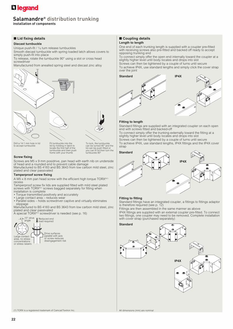
Smooth diecast turnbuckle with spring loaded latch allows covers to simply push-fit into place
To release, rotate the turnbuckle 90° using a slot or cross head screwdriver
Manufactured from anealled spring steel and diecast zinc alloy
Large contactarea, no stressconcentrationsor stress raisers
Drive surfacesparallel with axisof screw reducesdisengagement risk
Reduced endload required
15° driveangle
Screw fixing
Screws are M5 x 9 mm posidrive, pan head with earth nib on underside of head and a rounded end to prevent cable damageManufactured to BS 4183 and BS 3643 from low carbon mild steel, zinc plated and clear passivated
Tamperproof screw fixing
A M5 x 8 mm pan head screw with the efficient high torque TORX®(1) recessTamperproof screw fix lids are supplied fitted with mild steel plated screws with TORX®(1) screws bagged separately for fitting when installation is complete• Torque transmitted positively and accurately• Large contact area – reduces wear• Parallel sides – holds screwdriver captive and virtually eliminates
slippageManufactured to BS 4183 and BS 3643 from low carbon mild steel, zinc plated and clear passivatedA special TORX®(1) screwdriver is needed (see p. 16)
Drill a 14·1 mm hole in lid to accept turnbuckle
Fit turnbuckle into the lid by holding in latch to locate the first half of the turnbuckle and then push home with your thumb
To lock, the turnbuckle can be turned 90° and the lid can be push fitted or you can fit lid then turn the turnbuckle 90°
■ Coupling detailsLength to length
One end of each trunking length is supplied with a coupler pre-fitted with receiving screws also pre-fitted and backed off ready to accept opposing trunking end
To connect simply offer the open end internally toward the coupler at a slightly higher level until body locates and drops into slot
Screws can then be tightened by a couple of turns until secure
To achieve IP4X, use standard lengths and simply click the cover strap over the joint
(1) TORX is a registered trademark of Camcat/Textron Inc.
Fitting to length
Standard fittings are supplied with an integrated coupler on each open end with screws fitted and backed-off
To connect simply offer the trunking externally toward the fitting at a slightly higher level until body locates and drops into slot
Screws can then be tightened by a couple of turns until secure
To achieve IP4X, use standard lengths, IP4X fittings and the IP4X cover strap
Fitting to fitting
Standard fittings have an integrated coupler, a fittings to fittings adaptor is therefore required (see p. 12)
Fittings are then assembled in the same manner as above
IP4X fittings are supplied with an external coupler pre-fitted. To connect two fittings, one coupler may need to be removed. Complete installation with cover strap (purchased separately)
Salamandre® distribution trunking installation of components
Salamandre® distribution trunking drilling information with dimensions and technical information
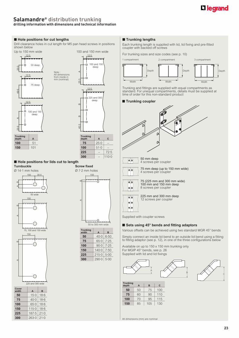
■ Hole positions for cut lengths
Drill clearance holes in cut length for M5 pan head screws in positions shown below
50 deep
12·5
25·0
75 deep
12·5
49·5
100 and 150deep
12·5
25·5
A
100 and 150deep
12·5
25·3
A
225 and 300deep
12·5
40·3
BB
■ Hole positions for lids cut to length
Coverwidth A B
50 15·0 18·6
75 40·0 18·6
100 65·0 18·6
150 115·0 18·6
225 187·5 21·0
300 263·0 21·0
50 wide
150 35·0
BA
75, 100 and 150 wide
150
BA
225 and 300 wide
150
BA
Trunkingwidth A B
50 40·0 6·50
75 65·0 7·25
100 90·0 7·25
150 140·0 7·50
225 215·0 5·00
300 290·0 5·00
150
BA
Note :All dimensions from inside in mm (nominal)
Up to 150 mm wide 100 and 150 mm wide
Screw fixed
Ø 7·2 mm holes
Turnbuckle
Ø 14·1 mm holes
50 to 300 mm wide
■ Trunking lengths
Each trunking length is supplied with lid, lid fixing and pre-fitted coupler with backed off screws
For trunking sizes and size codes (see p. 10)
Trunking and fittings are supplied with equal compartments as standard. For unequal compartments, details must be supplied at time of order for this non-standard product
Width
Depth
Width
Depth
Width
Depth
1 compartment 2 compartment 3 compartment
■ Sets using 45° bends and fitting adaptors
■ Trunking coupler
Trunking depth A B C
50 50 75 100
75 60 90 110
100 70 95 115
150 85 105 130
Various offsets can be achieved using two standard MGR 45° bends
Simply connect an inside lid bend to an outside lid bend using a fitting to fitting adaptor (see p. 12), in one of the three configurations below
Available on up to 150 x 150 mm trunking only
For MGIP 45° bends, see p. 26
Supplied with lid and lid fixings
AB
C
50 mm deep4 screws per coupler
75 mm deep (up to 150 mm wide)4 screws per coupler
75 (225 mm and 300 mm wide)100 mm and 150 mm deep8 screws per coupler
Salamandre® distribution trunkingstandard fittings – dimensions and technical information
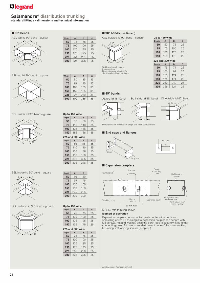
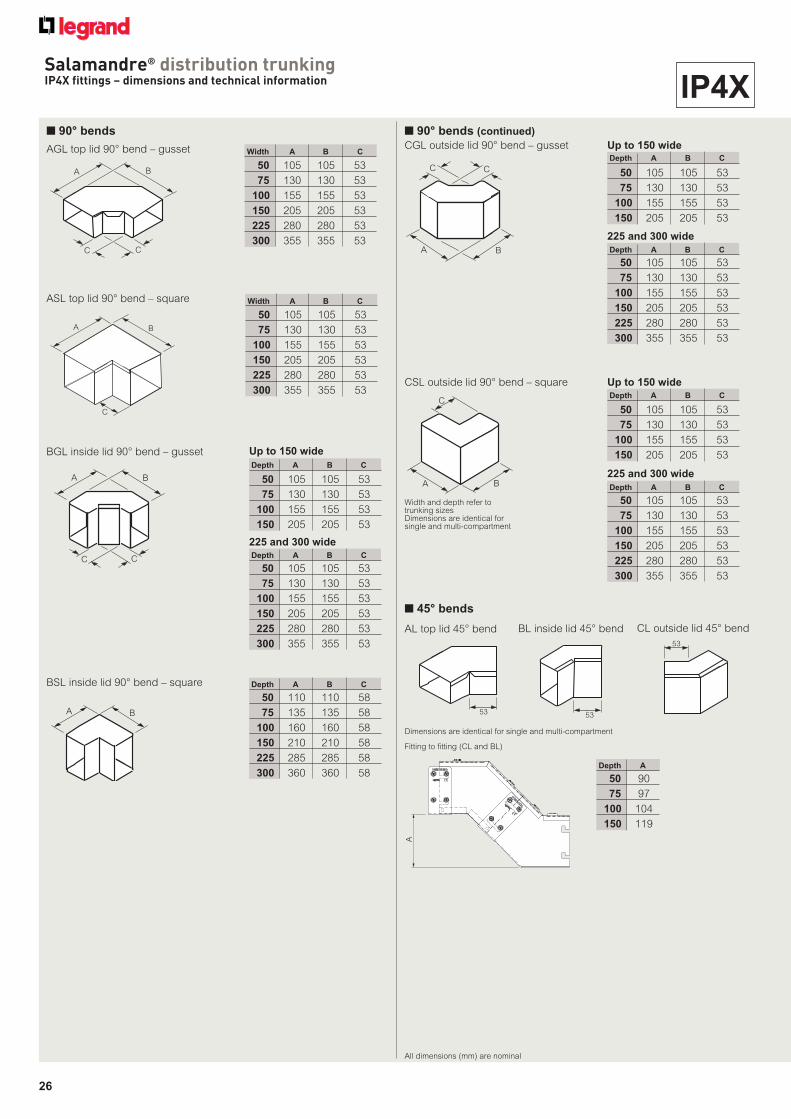
■ 90° bends
BA
C C
AGL top lid 90° bend – gusset Width A B C
50 75 75 25
75 100 100 25
100 125 125 25
150 175 175 25
225 251 251 25
300 326 326 25
BA
C
ASL top lid 90° bend – square Width A B C
50 50 85 35
75 75 110 35
100 100 135 35
150 150 185 35
225 225 260 35
300 300 335 35
Depth A B C
50 86 86 35
75 110 110 35
100 136 136 35
150 186 186 35
BA
BSL inside lid 90° bend – square Depth A B
50 50 50
75 75 75
100 100 100
150 150 150
225 225 225
300 300 300
Depth A B C
50 75 75 25
75 100 100 25
100 125 125 25
150 175 175 25
225 250 250 25
300 325 325 25
A B
CC
CGL outside lid 90° bend – gusset
225 and 300 wide
Up to 150 wide
Depth A B C
50 86 86 35
75 110 110 35
100 136 136 35
150 186 186 35
225 305 305 35
300 336 336 35
Depth A B C
50 75 74 25
75 100 99 25
100 125 124 25
150 175 174 25
225 250 249 25
300 325 324 25
BA
C
CSL outside lid 90° bend – square
Width and depth refer to trunking sizesDimensions are identical for single and multi-compartment
Up to 150 wide
225 and 300 wide
BA
CC
BGL inside lid 90° bend – gusset
225 and 300 wide
Up to 150 wide
■ 45° bends
Dimensions are identical for single and multi-compartment
35 35
35
AL top lid 45° bend BL inside lid 45° bend CL outside lid 45° bend
All dimensions (mm) are nominal
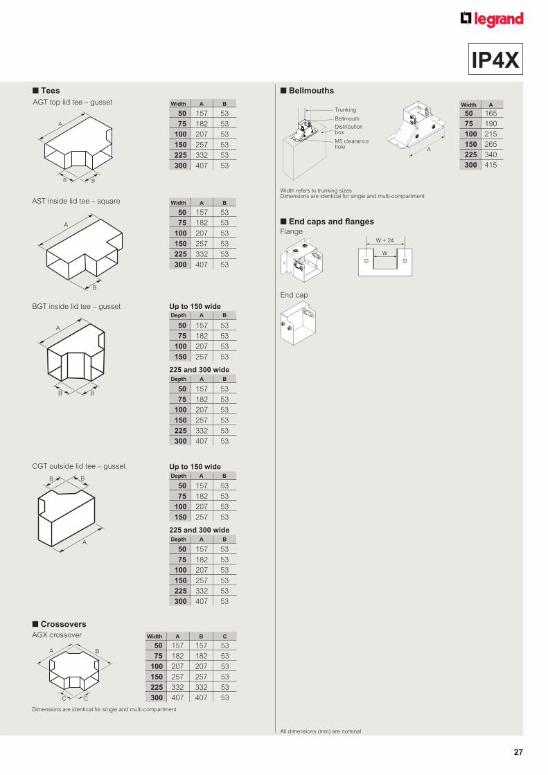
■ End caps and flanges
W + 24
W
Flange
Stop end
Depth A B C
50 75 75 25
75 100 100 25
100 125 125 25
150 175 175 25
Depth A B C
50 50 75 25
75 75 100 25
100 100 125 25
150 150 175 25
■ 90° bends (continued)
Trunking lid 25 mm
Outer shrouding
cover Self tapping screw
M5 screws, nuts and washers
80 mm max.
Inner slide body50 mm min.
Trunking bodyEarth wire 4 mm2
green / yellow
126 mm
Method of operation
Expansion couplers consist of two parts : outer slide body and shrouding cover. Fit trunking into expansion coupler and secure with M5 screws, nut and washer, ensuring earth lead is securely fitted underconnecting point. Fit outer shrouded cover to one of the main trunkinglids using self tapping screws (supplied)
Width and Depth refer to trunking sizesDimensions are identical for single and multi-compartment
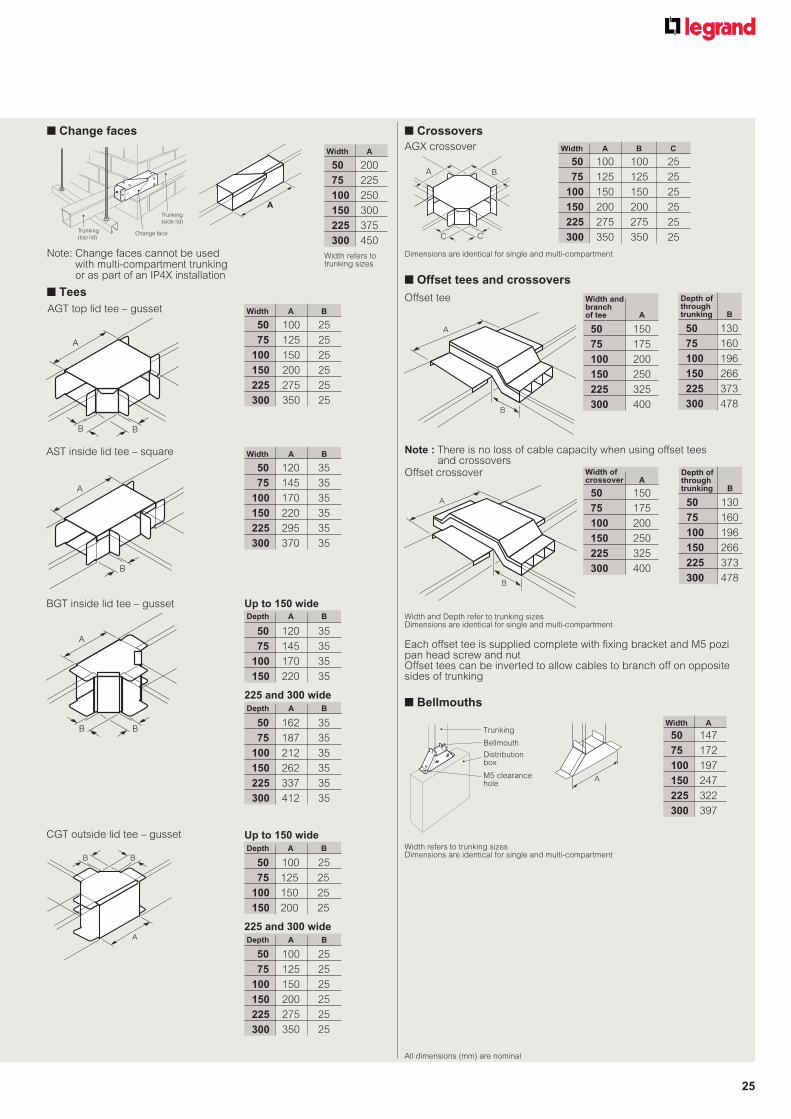
Each offset tee is supplied complete with fixing bracket and M5 pozi pan head screw and nutOffset tees can be inverted to allow cables to branch off on opposite sides of trunking
A
B
Offset crossover
A
B
Offset tee
Note : There is no loss of cable capacity when using offset tees and crossovers
■ Crossovers
Dimensions are identical for single and multi-compartment
A B
C C
AGX crossover Width A B C
50 100 100 25
75 125 125 25
100 150 150 25
150 200 200 25
225 275 275 25
300 350 350 25
All dimensions (mm) are nominal
■ Bellmouths
A
Width refers to trunking sizesDimensions are identical for single and multi-compartment
Width A
50 147
75 172
100 197
150 247
225 322
300 397
Trunking
Bellmouth
Distributionbox
M5 clearance hole
50 130
75 160
100 196
150 266
225 373
300 478
Depth of through trunking B
50 150
75 175
100 200
150 250
225 325
300 400
Width and branch of tee A
50 130
75 160
100 196
150 266
225 373
300 478
Depth of through trunking B
50 150
75 175
100 200
150 250
225 325
300 400
Width of crossover A
■ Change faces
A
Change face
Trunking
(side lid)
Trunking
(top lid)
Note: Change faces cannot be used with multi-compartment trunking or as part of an IP4X installation
Salamandre® distribution trunkingaccessories – dimensions and technical information
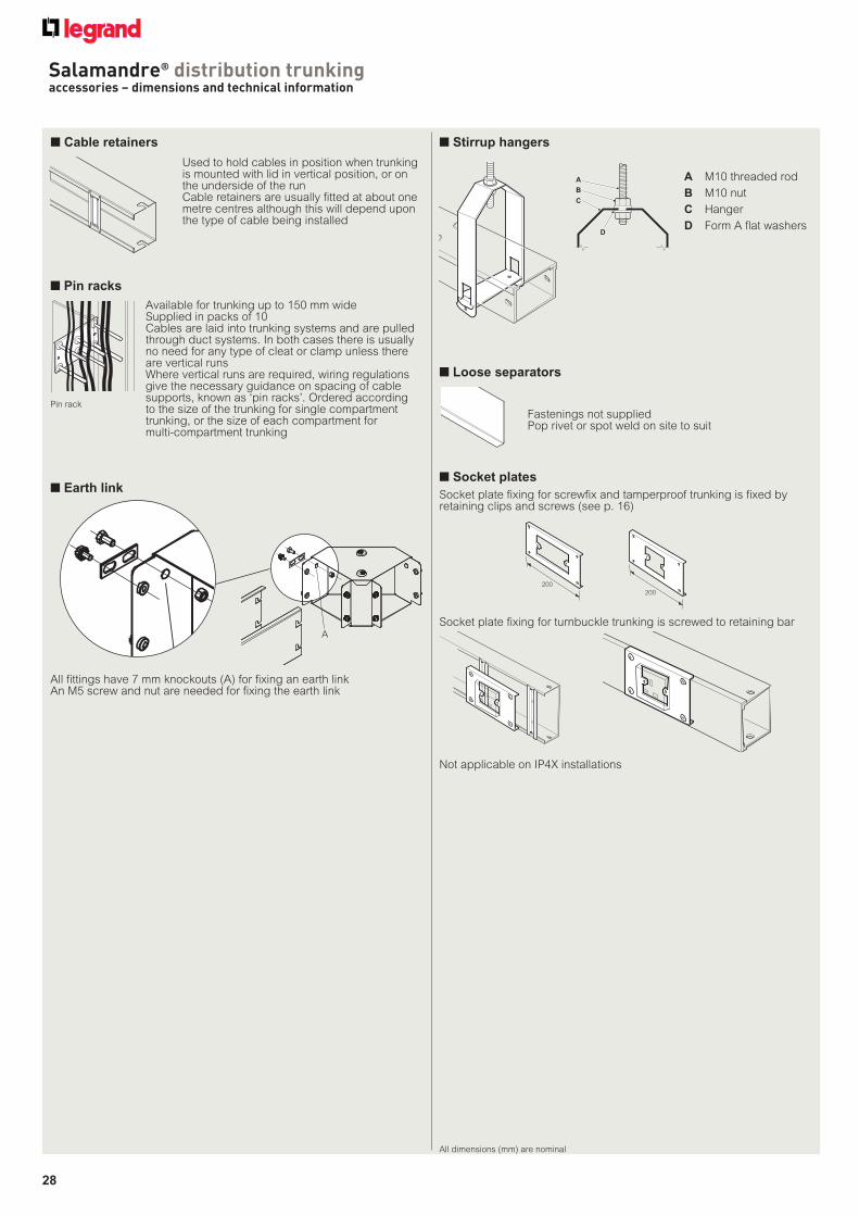
■ Earth link
All fittings have 7 mm knockouts (A) for fixing an earth linkAn M5 screw and nut are needed for fixing the earth link
■ Pin racks
Available for trunking up to 150 mm wideSupplied in packs of 10Cables are laid into trunking systems and are pulled through duct systems. In both cases there is usually no need for any type of cleat or clamp unless there are vertical runsWhere vertical runs are required, wiring regulations give the necessary guidance on spacing of cable supports, known as ‘pin racks’. Ordered according to the size of the trunking for single compartment trunking, or the size of each compartment for multi-compartment trunking
Pin rack
■ Loose separators
Fastenings not suppliedPop rivet or spot weld on site to suit
■ Socket plates
Socket plate fixing for screwfix and tamperproof trunking is fixed by retaining clips and screws (see p. 16)
Socket plate fixing for turnbuckle trunking is screwed to retaining bar
200
200
■ Stirrup hangers
A M10 threaded rod
B M10 nut
C Hanger
D Form A flat washers
A
B
C
D
■ Cable retainers
Used to hold cables in position when trunking is mounted with lid in vertical position, or on the underside of the runCable retainers are usually fitted at about one metre centres although this will depend upon the type of cable being installed
Salamandre® distribution trunking installation notes
■ Earth bonding
Cable trunking and ducting systems are designed to carry single insulated cables, and such systems must therefore provide the secondary protection required by the Wiring Regulations. This means trunking and ducting systems must be earth bonded together, and then connected to a suitable earth point. Salamandre trunking is designed to provide such earth bonding, provided that the system is fully assembled with all manufacturer’s original components, including fixings, and that all fixings are fully tightened. This is achieved by a combination of serrations under the head of the fixing screws and the internal barbs on the fixing bars
Salamandre
Legrand CE
■ Electromagnetic Compatibility (EMC)
Cable trunking and ducting systems are considered passive under normal conditions in respect of electromagnetic influences. The installation of current carrying cables may cause emissions and these cables may also be influenced by electromagnetic signals from elsewhere, but the degree of influence will depend on the nature of the installation and the apparatus connected to the system. Specific information relating to the details of cable separation required according to the type of signal, and further information on the subject of EMC, is provided in the relevant Standards and Regulations. However as a basic principle, if power and signal cables are run in separate compartments of a metal trunking system, then the metal segregation will significantly reduce the possibility of one circuit having undesirable effect influence upon another
■ Supporting cable trunking systems
The coupler between all types of cable trunking lengths is to provide electrical and mechanical connection between the lengths; it does not provide a load bearing connection between lengths. Consequently each length must be fully supported so that there is no significant bending force applied to the coupler
Each individual length of trunking is strong enough to carry the maximum number of cables that can be physically fitted into the trunking whilst still being able to correctly fit the cover without applying force. All supports must therefore be designed to carry each length individually without relying on the coupler
■ IP4X vs IPXXD
The index of protection is defined in BS EN 60529 – Degree of protection of enclosures of electrical equipment
IP4X
Protected against solid bodies greater than 1mm in diameter. The test uses a 1mm diameter, 100mm long test probe / wire. The probe is applied with a force of 1N+10% and is not allowed to enter the enclosure being tested
IPXXD
Solid bodies no greater than 1mm in diameter may enter the top of the enclosure but will remain clear of hazardous parts. The test uses a 1mm diameter, 100mm long test probe / wire. The top of the enclosure may allow entry of the 100mm long test wire, however the wire is not allowed to touch any hazardous parts within the enclosure
Approximately 50% of cable capacity is lost when using multi-compartment fittings
Where tees or fourway / crosses are used on a multi-compartment system, ‘crossover bridges’ must be used
Crossover bridges are supplied as a removeable item, allowing the cables for compartment A to be laid into the trunking. Once these are in position, the crossover bridge can be fitted, and the cables for compartment B laid into position. This obviates the need for threading any cables through the crossover bridge
Examples :
■ Compartment tees
AAB
B
A
B2 compartment
A ABC
B
C
A
B
C3 compartment
Approximately 50% of cable capacity is lost when using multi-compartment tees
Examples :
Salamandre® distribution trunkingmulti-compartment crossovers and compartment tees