537 East Pete Rose Way, Suite 200 | Cincinnati, Ohio 45202 | V 513.721.8080 | 800.469.4949 | F 513.721.8181 | www.colerussell.com Commercial | Education | Government | Hospitality | Housing | Retail SALISBURY FIRE STATION #2 SALISBURY, MARYLAND June 2008 C+RA Commission Number: 407005 TABLE OF CONTENTS Executive Summary Tab 1 Options Description and Pros/ Cons Tab 2 Probable Cost Analysis Tab 3 Options Conceptual Plans Tab 4 Space Needs Analysis and Space Diagrams Tab 5 Structural Reports Tab 6
Transcript
537 East Pete Rose Way, Suite 200 | Cincinnati, Ohio 45202 | V 513.721.8080 | 800.469.4949 | F 513.721.8181 | www.colerussell.com
C o m m e r c i a l | E d u c a t i o n | G o v e r n m e n t | H o s p i t a l i t y | H o u s i n g | R e t a i l
SALISBURY FIRE STATION #2 SALISBURY, MARYLAND June 2008 C+RA Commission Number: 407005
TABLE OF CONTENTS Executive Summary Tab 1 Options Description and Pros/ Cons Tab 2 Probable Cost Analysis Tab 3 Options Conceptual Plans Tab 4 Space Needs Analysis and Space Diagrams Tab 5 Structural Reports Tab 6
Salisbury Fire Station #2 - Feasibility Study June, 2008
Page 2 of 2
537 East Pete Rose Way, Suite 200, Cincinnati, Ohio 45202 | V 513.721.8080 | F 513.721.8181 | www.colerussell.com
537 East Pete Rose Way, Suite 200 | Cincinnati, Ohio 45202 | V 513.721.8080 | 800.469.4949 | F 513.721.8181 | www.colerussell.com
C o m m e r c i a l | E d u c a t i o n | G o v e r n m e n t | H o s p i t a l i t y | H o u s i n g | R e t a i l
SALISBURY FIRE STATION #2 SALISBURY, MARYLAND June 2008 C+RA Commission Number: 407005
EXECUTIVE SUMMARY The purpose of this Feasibility Study is to assist the Salisbury Fire Department in decision-
making related to future physical facilities for Fire Station #2. The study began with the
development of a program needs assessment for the Fire Department Administration, Operations,
and Support. The final needs assessment and diagrams developed to determine the square
footage needs of each space are included in this document.
Cole + Russell Architects conducted interviews with key stakeholders and personnel to confirm
space needs for the various department personnel and to confirm the objectives for this
assessment. Key considerations of this study include site access for pedestrians and vehicles,
existing facility re-use, required upgrades to facilities, existing facility ability to support program
needs, and cost. The existing facility was evaluated by the structural engineer to assess the
viability of renovation, expansion, and code-related structural improvements. The report of these
findings and recommendations for corrections are included in this report.
Three options are evaluated to accommodate the space needs for Fire Station #2. The first two
options incorporate a reduced program that does not fully meet the needs of the Department,
while the third option includes the full Department needs in a new facility. Option 1 consists of
renovations to the existing apparatus bays and the existing living spaces, with small additions to
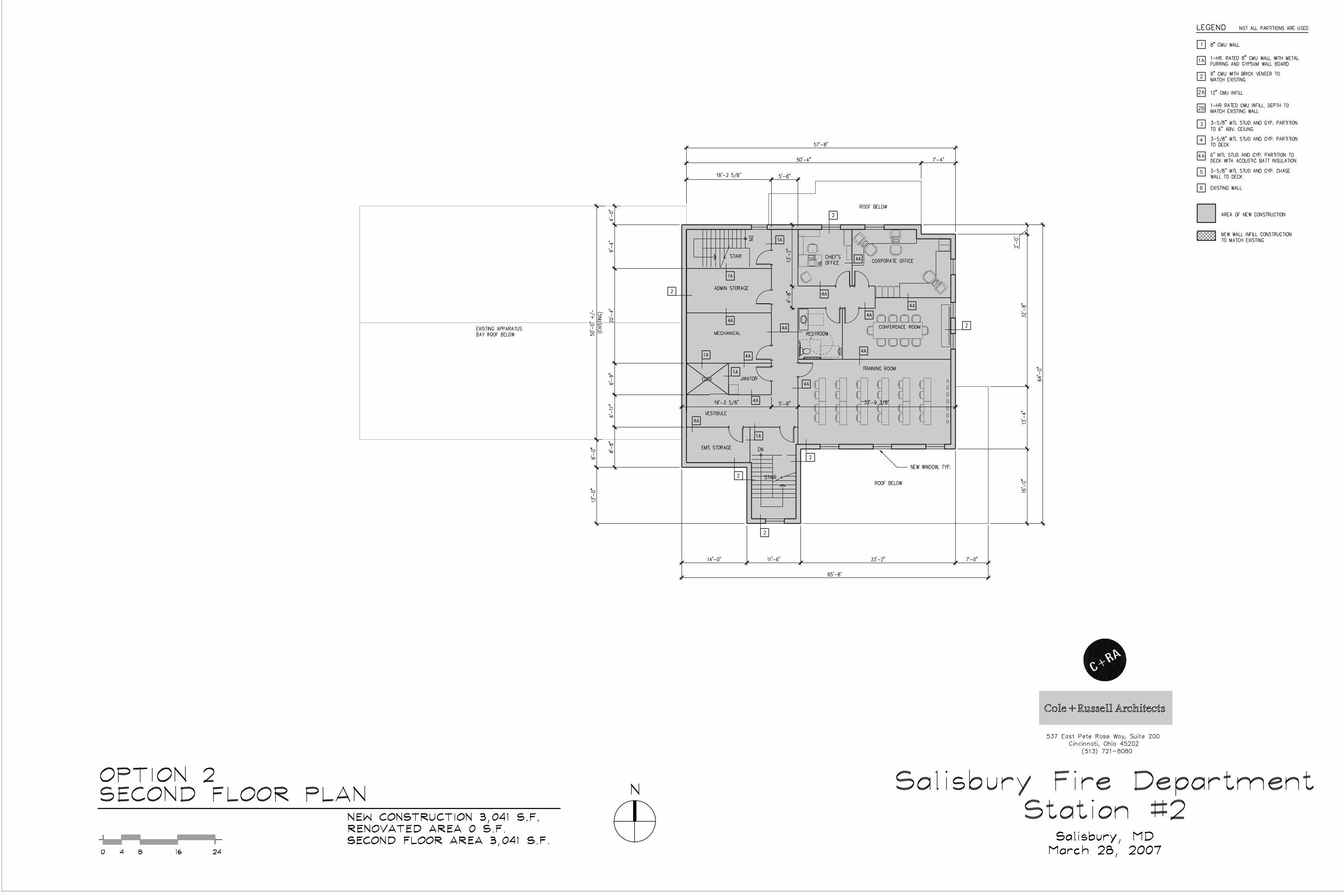
the existing building as allowed by the limited site area. Option 2 evaluates demolishing the
existing living, office, and support spaces and replacing this portion of the building with new
construction as allowed by the limited site area. The existing apparatus bays are included as
renovations. Finally, Option 3 evaluates the full needs of the Fire Department within a new
building on an adjacent site.
More detailed information and a description of each option is included in the report that follows,
with a breakdown of probable cost information. Other factors may affect the probable cost of this
facility that are not within the scope of this report including geo-technical investigations and
environmental studies related to the specific sites and existing building.
Option #3 provides the full needs of the department where Option #1 and Option #2 fall short
due to site and building limitations. Option #3 also improves on the first two options in function
as it provides the personnel flow necessary within a fire station facility. Finally, Option #3
provides these requirements at a cost per square foot that provides a more effective use of the
Salisbury Fire Station #2 - Feasibility Study June, 2008
Page 2 of 2
537 East Pete Rose Way, Suite 200, Cincinnati, Ohio 45202 | V 513.721.8080 | F 513.721.8181 | www.colerussell.com
department funds. Therefore, it is the opinion of Cole + Russell Architects that Option #3 is the best option to meet the future needs of the Salisbury Fire Department for Station #2.
537 East Pete Rose Way, Suite 200 | Cincinnati, Ohio 45202 | V 513.721.8080 | 800.469.4949 | F 513.721.8181 | www.colerussell.com
C o m m e r c i a l | E d u c a t i o n | G o v e r n m e n t | H o s p i t a l i t y | H o u s i n g | R e t a i l
SALISBURY FIRE STATION #2 - FEASIBILITY STUDY OPTION 1 CITY OF SALISBURY, MARYLAND FIRE DEPARTMENT Date: June 2008 C+RA Commission Number: 407005
OVERVIEW The goal of Option 1 is to address the programming needs outlined in the “Preliminary Space Needs Analysis – Options 1 and 2” prepared by Cole+Russell Architects on 10.02.07 (revised 10.22.07), within the existing building and with minimal impact to the site in the form of new additions to the original building. Below is a narrative of the proposed renovation followed by single line demolition and floor plans.
EXISTING BUILDING The existing building is comprised of three parts: the original 2-story, multi-wythe brick structure built in 1930, a masonry apparatus bay addition on the west end of the building built in 1990, and a masonry one-story connection between the original building and apparatus bay addition (assumed to be built in 1990 with the apparatus bay addition). Refer to the Structural Evaluation provided by Kenneth B. Robinson & Associates dated January 17, 2008 (attached) for detailed information.
The apparatus bay addition is currently being used to house four vehicles, and is also used as storage space for support equipment including (but not limited to) turn-out gear, SCBA equipment, tools and a work bench, tables and chairs, and hoses. The one-story connection contains the alarm room, restrooms, an office, and janitor’s room. On the first floor of the original building there is a lobby/lounge, kitchen/dining room, and the original apparatus bay which is being used as a fitness area as well as to house one vehicle. On the second floor of the original building there is a restroom, offices, and a day room/meeting room. The basement of the original building houses mechanical and electrical equipment and is also used for miscellaneous storage.
Also on the site is a parking area to the west of the apparatus bay, a wood framed storage shed to the west of that parking area, and a generator on a concrete pad north of the original building.
City of Salisbury, Fire Department Salisbury Fire Station #2 - Feasibility Study, Option 1
June, 2008 Page 2 of 4
537 East Pete Rose Way, Suite 200, Cincinnati, Ohio 45202 | V 513.721.8080 | F 513.721.8181 | www.colerussell.com
ARCHITECTURAL
The proposed renovation utilizes the existing apparatus bay addition with modifications to the south facing wall to accommodate three (3) 14’ doors in place of the existing pair of 22’ doors. There will be no modifications to the apparatus bay floor, ceiling, roof, or windows, except where repair is required. The bay will house three vehicles, hoses, and turn-out gear in lockers. Mechanical systems may need to be modified or replaced to bring them up to current energy code standards.
There will be a complete interior remodel of both stories of the original part of the building and the connection. This includes complete removal of interior partitions, casework, fixtures and equipment with the following exceptions: the basement, stair, mechanical chase on both floors, and second floor restroom toilet waste and vent pipes (and adjacent walls as indicated). The north facing window in the northwest corner of the second floor will be replaced by two windows in the existing opening to accommodate a new partition (similar to the existing north-facing window in the existing second floor restroom/stairwell). Existing floor drains not used for new work shall be removed and the floor patched and leveled to match existing. Renovated areas are reconfigured to provide (on the first floor) a training room, conference room, administrative offices, storage room, unisex restroom, fitness room, alarm room EMS storage, and SCBA equipment/janitor room. Renovated areas on the second floor include modifications to the existing restroom, two additional unisex restrooms, a laundry room, dining room, day room and an extension of the new construction bunkroom.
The proposed renovation includes new, two-story additions on the southwest and northeast sides of the original building. On the first floor these additions include a new entrance to the facility, a second stair, administrative offices, fitness room, an elevator and elevator machine room. The Second Floor of the additions will house an elevator/stair lobby, kitchen, and bunkroom. Interior partitions shall be metal stud with gypsum wall board. New aluminum windows will be of comparable size and shape to the original building windows, and the entry vestibule doors shall be aluminum storefront with sidelites.
The existing roof of this building appears to be in good condition. The only work on the roof shall be penetrations for new equipment. Existing piping for equipment to be removed shall be capped in a weather tight manner and abandoned in place. New roof structures will consist of wood or metal trusses creating pitched rooflines with shingles.
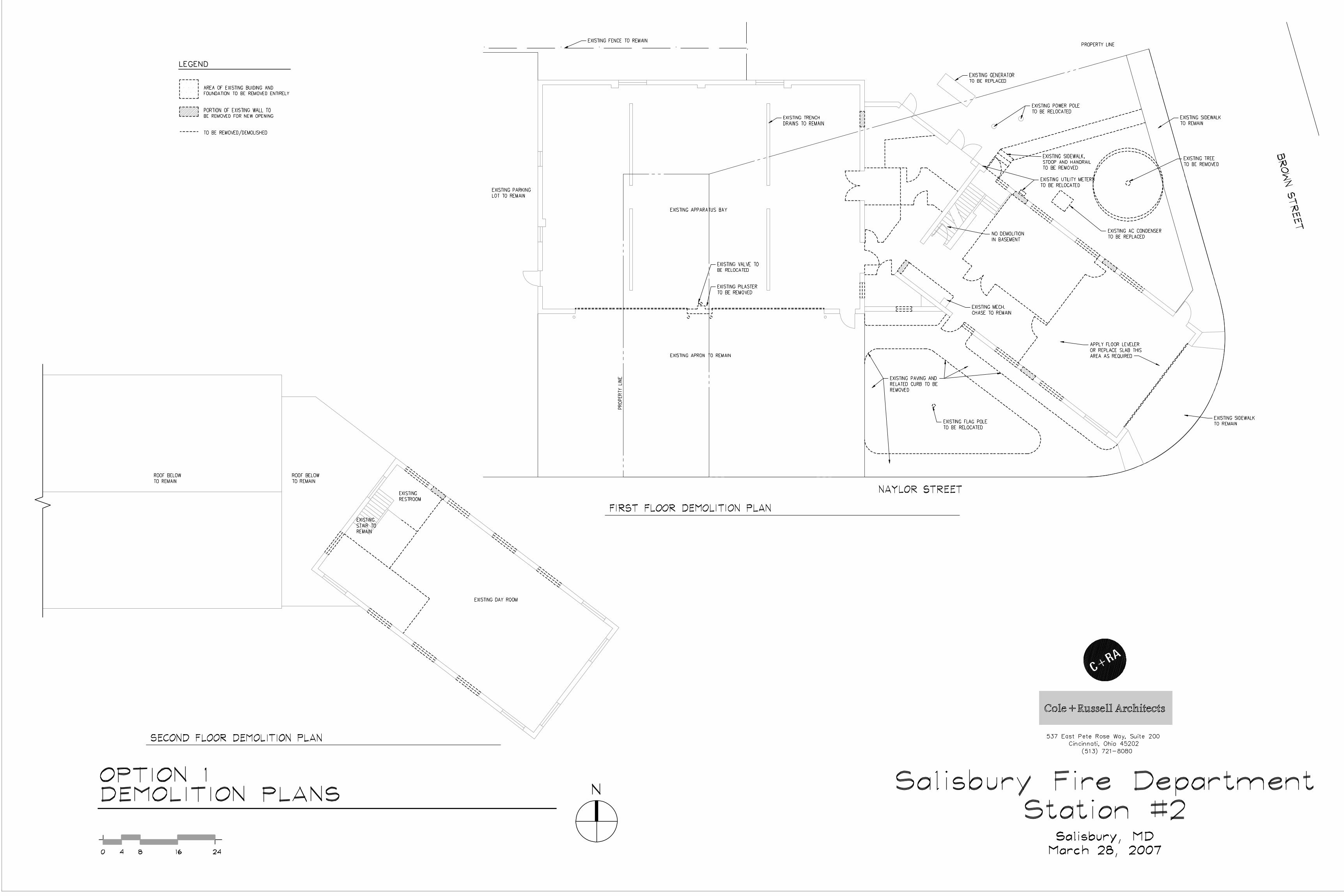
SITE WORK The concrete apron in front of the apparatus bay, adjacent asphalt parking area, and wood shed will not be modified in this project. The raised curbs and paving (where there is currently a flag pole) adjacent to and abutting the original building shall be removed to accommodate new construction; the flag pole shall be relocated. The brick stoop and steps on the northeast side of the original building and the associated concrete walk shall be removed up to the existing sidewalk adjacent on Brown Street. An existing tree and planting area on the northeast side of the original building will be removed to accommodate new construction. Utility meters, an AC condensing unit, and two utility poles on the northeast corner will be relocated, to be coordinated with the governing utility provider.
City of Salisbury, Fire Department Salisbury Fire Station #2 - Feasibility Study, Option 1
June, 2008 Page 3 of 4
537 East Pete Rose Way, Suite 200, Cincinnati, Ohio 45202 | V 513.721.8080 | F 513.721.8181 | www.colerussell.com
STRUCTURAL Refer to the Structural Evaluation provided by Kenneth B. Robinson & Associates dated January 17, 2008 (attached) for detailed information. All modifications to bearing walls shall follow the recommendations provided in the Structural Evaluation.
A pilaster between the overhead doors in the existing apparatus bay addition will have to be removed to accommodate the new overhead doors. In-fill construction for these modifications to the apparatus bay exterior bearing walls shall be CMU with brick veneer to match existing. In-fill construction for the interior CMU walls adjacent to the one-story connection shall be CMU to match existing.
New openings with new beams and columns/pilasters will be required in the exterior walls of the original building on both floors to accommodate new construction. Existing window and door openings not used for new work, shall be filled in with 12” CMU.
The new additions shall consist of insulated CMU/brick veneer cavity bearing walls on poured in place concrete footings. The brick veneer shall match existing. The stairs, elevator and elevator machine room shall be enclosed in 8” CMU 1-hour construction. Floors are to be slab on grade for the first floor and steel framing with light weight concrete topping for the second floor. New sloped roof shall be comprised of steel trusses with shingles to match existing. Flat roof elements shall be an insulated membrane roofing system sloped 1/4” per foot towards scuppers that drain water runoff into downspouts.
MECHANICAL A detailed analysis on existing and proposed new systems has not been performed as part of this report, but it is assumed that a new mechanical system will be needed and modifications to the existing electrical system are required to meet current codes. The new mechanical system will consist of small commercial furnaces/ AC units with condenser locations on the roof or on the ground in the back of the facility.
PROS AND CONS Pros
Existing facility re-use
Initial Cost is lowest of the options Cons
Temporary Facilities would be required during construction
This option does not meet the full needs of the department
Staff parking is not accommodated
Site is limited
Trucks must back into bays and may not accommodate future apparatus size
Turn-Out-Gear is located in the apparatus bays
Limited views for apparatus as they egress the station
City of Salisbury, Fire Department Salisbury Fire Station #2 - Feasibility Study, Option 1
June, 2008 Page 4 of 4
537 East Pete Rose Way, Suite 200, Cincinnati, Ohio 45202 | V 513.721.8080 | F 513.721.8181 | www.colerussell.com
Apparatus cannot fully park on the concrete apron
537 East Pete Rose Way, Suite 200 | Cincinnati, Ohio 45202 | V 513.721.8080 | 800.469.4949 | F 513.721.8181 | www.colerussell.com
C o m m e r c i a l | E d u c a t i o n | G o v e r n m e n t | H o s p i t a l i t y | H o u s i n g | R e t a i l
SALISBURY FIRE STATION #2 - FEASIBILITY STUDY OPTION 2 CITY OF SALISBURY, MARYLAND FIRE DEPARTMENT Date: June 2008 C+RA Commission Number: 407005
OVERVIEW The goal of Option 2 is to address the programming needs outlined in the “Preliminary Space Needs Analysis – Options 1 and 2” prepared by Cole+Russell Architects on 10.02.07 (revised 10.22.07), by modifying the apparatus bay addition, demolishing the original building and one-story connection, and replacing them with new construction. Below is a narrative of the proposed renovation followed by single line demolition and floor plans.
EXISTING BUILDING The existing building is comprised of three parts: the original 2-story, multi-wythe brick structure built in 1930, a masonry apparatus bay addition on the west end of the building built in 1990, and a masonry one-story connection between the original building and apparatus bay addition (assumed to be built in 1990 with the apparatus bay addition). Refer to the Structural Evaluation provided by Kenneth B. Robinson & Associates dated January 17, 2008 (attached) for detailed information.
The apparatus bay addition is currently being used to house four vehicles, and is also used as storage space for support equipment including (but not limited to) turn-out gear, SCBA equipment, tools and a work bench, tables and chairs, and hoses. The one-story connection contains the alarm room, restrooms, an office, and janitor’s room. On the first floor of the original building there is a lobby/lounge, kitchen/dining room, and the original apparatus bay which is being used as a fitness area as well as to house one vehicle. On the second floor of the original building there is a restroom, offices, and a day room/meeting room. The basement of the original building houses mechanical and electrical equipment and is also used for miscellaneous storage.
Also on the site is a parking area to the west of the apparatus bay, a wood framed storage shed to the west of that parking area, and a generator on a concrete pad north of the original building.
City of Salisbury, Fire Department Salisbury Fire Station #2 - Feasibility Study, Option 2
June, 2008 Page 2 of 3
537 East Pete Rose Way, Suite 200, Cincinnati, Ohio 45202 | V 513.721.8080 | F 513.721.8181 | www.colerussell.com
ARCHITECTURAL The proposed renovation utilizes the existing apparatus bay addition with modifications to the south facing wall to accommodate three (3) 14’ doors in place of the existing pair of 22’ doors. There will be no modifications to the apparatus bay floor, ceiling, roof, or windows, except where repair is required. The bay will house three vehicles, hoses, and turn-out gear in lockers. Mechanical systems may need to be modified or replaced to bring them up to current energy code standards.
The original building and the one-story connection to the apparatus bay will be completely demolished, to be replaced by new construction. New construction will consist of concrete masonry bearing walls with brick veneer and sloped roof. New aluminum windows will be of comparable size and shape to the original building windows, and the entry vestibule doors shall be aluminum storefront with sidelites. Partitions shall be metal stud with gypsum wall board. On the first floor this addition includes a new entrance to the facility, alarm room, SCBA and storage room, kitchen, dining room, day room, bunk room, fitness room, laundry, and three unisex restrooms. The Second Floor of the addition will have EMS storage, janitor room, training room, conference room, administrative offices, a unisex restroom, storeroom, and a mechanical room. There will be two sets of stairs, and one elevator.
The existing apparatus bay roof shall remain undisturbed except where it abuts new construction. The existing roof shall be patched with shingles to match existing at the intersection with new construction. New construction will consist of wood or metal trusses creating pitched rooflines with shingles.
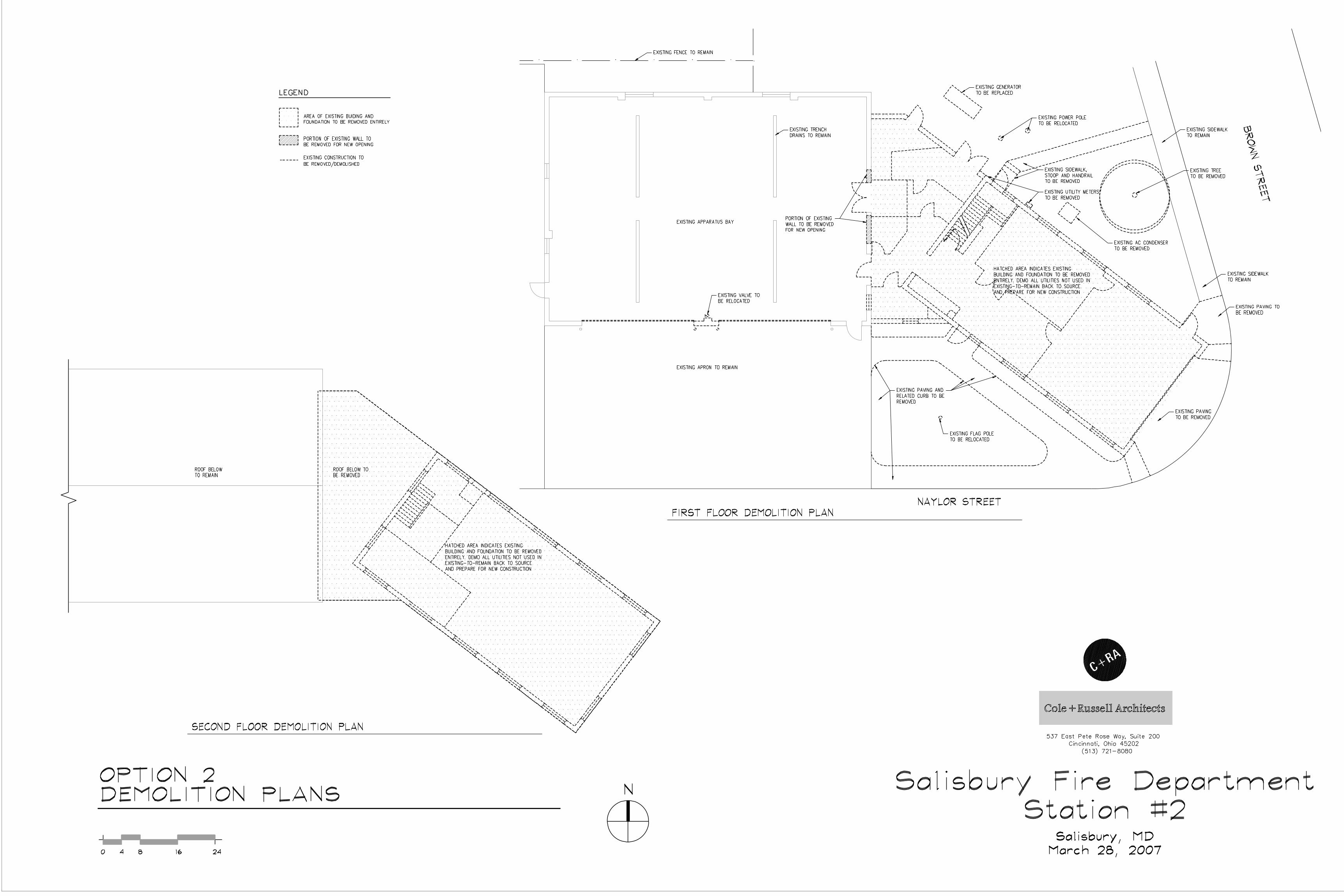
SITE WORK The concrete apron in front of the apparatus bay, adjacent asphalt parking area, and wood shed will not be modified in this project. The raised curbs and paving (where there is currently a flag pole) adjacent to and abutting the original building shall be removed to accommodate new construction; the flag pole shall be relocated. The sloped paving just outside the original apparatus bay shall be removed and replaced by a new side walk integrated into the existing sidewalks on and adjacent to the site. The brick stoop and steps on the northeast side of the original building and the associated concrete walk shall be removed up to the existing sidewalk on Brown Street. Utility meters, an AC condensing unit, and an existing tree and planting area will be removed to accommodate new construction. The generator and two power line poles on the northeast corner will be relocated, to be coordinated with the governing utility provider.
City of Salisbury, Fire Department Salisbury Fire Station #2 - Feasibility Study, Option 2
June, 2008 Page 3 of 3
537 East Pete Rose Way, Suite 200, Cincinnati, Ohio 45202 | V 513.721.8080 | F 513.721.8181 | www.colerussell.com
STRUCTURAL Refer to the Structural Evaluation provided by Kenneth B. Robinson & Associates dated January 17, 2008 (attached) for detailed information on repair of existing construction. All modifications to bearing walls shall follow the recommendations provided in the Structural Evaluation.
A pilaster between the overhead doors in the existing apparatus bay addition will have to be removed to accommodate the new overhead doors. In-fill construction for these modifications to the apparatus bay exterior bearing walls shall be CMU with brick veneer to match existing. In-fill construction for the interior CMU walls adjacent to the one-story connection shall be CMU to match existing.
The new structure shall consist of insulated CMU/brick veneer cavity bearing walls on poured in place concrete footings. Floors are to be slab on grade for the first floor and steel framing with light weight concrete topping for the second floor. The stairs, elevator and elevator machine room shall be enclosed in 8” CMU 1-hour construction. New sloped roof shall be comprised of steel trusses with shingles to match existing. Flat roof elements shall be an insulated membrane roofing system sloped 1/4” per foot towards scuppers that drain water runoff into downspouts.
MECHANICAL A detailed analysis on existing and proposed new systems has not been performed as part of this report, but it is assumed that a new mechanical and electrical system will be needed and modifications to the existing electrical system in the apparatus bays are required to meet current codes. The new mechanical system will consist of small commercial furnaces/ AC units with condenser locations on the roof or on the ground in the back of the facility.
PROS AND CONS Pros
Some existing facility re-use Cons
Temporary Facilities would be required during construction
This option does not meet the full needs of the department
Staff parking is not accommodated
Site is limited
Trucks must back into bays and may not accommodate future apparatus size
Turn-Out-Gear are located in the apparatus bays
Limited views for apparatus as they egress the station
537 East Pete Rose Way, Suite 200 | Cincinnati, Ohio 45202 | V 513.721.8080 | 800.469.4949 | F 513.721.8181 | www.colerussell.com
C o m m e r c i a l | E d u c a t i o n | G o v e r n m e n t | H o s p i t a l i t y | H o u s i n g | R e t a i l
SALISBURY FIRE STATION #2 - FEASIBILITY STUDY OPTION 3 CITY OF SALISBURY, MARYLAND FIRE DEPARTMENT Date: June 2008 C+RA Commission Number: 407005
OVERVIEW The goal of Option 3 is to address the programming needs outlined in the “Preliminary Space Needs Analysis” prepared by Cole+Russell Architects on 10.02.07 (revised 10.22.07), by constructing a new building across Brown Street from the existing Station #2 Facility. Below is a narrative of the proposed construction followed by a single line floor plan.
EXISTING BUILDING No existing structure present.
ARCHITECTURAL The proposed new building is across Brown Street from the existing Fire Station #2. The building is situated on the north east corner of Brown Street and Naylor Street, and faces Naylor Street. It is comprised of two parts, a drive through apparatus bay with access from Brown Street in the rear and to Naylor Street in front, and a single story support building including operations, administration, and dormitory. The total square footage is approximately 13,100 s.f. New construction consists of concrete masonry backup with brick veneer utilizing cavity wall construction. Roof lines contain pitched roofs with asphalt shingles.
SITE WORK Existing structures, pavement and vegetation, unverified at the writing of this study, shall be demolished and removed to accommodate new construction. All existing utilities are to be removed back to point of service connection. Utility equipment such as power poles or hydrants shall be relocated to accommodate new construction, to be verified and coordinated with the utility provider. Proposed site improvements include two parking areas; 6 spaces to the north, two of which are handicap van accessible, and 11 spaces to the west of the building. There are proposed sidewalks along the streets, from these sidewalks to the building and from the parking areas to the building. There is an opportunity to provide a decorative sidewalk and/or planting area around the flagpole in the front of the building if desired; a diagrammatic representation is included on the floor plan.
City of Salisbury, Fire Department Salisbury Fire Station #2 - Feasibility Study, Option 3
June, 2008 Page 2 of 2
537 East Pete Rose Way, Suite 200, Cincinnati, Ohio 45202 | V 513.721.8080 | F 513.721.8181 | www.colerussell.com
STRUCTURAL The new construction will be consistent with that of the new Salisbury Fire Headquarters. Footings shall be poured in place concrete. Exterior walls will be insulated CMU/brick veneer cavity bearing walls supporting steel bar joist and metal deck roof construction. Bearing height of roof joists over the apparatus bay and support area will be nominally 20’ while the bearing height for the administrative and dormitory portion of the building will be nominally 14’. Interior partitions in the apparatus bay support areas will consist of CMU. Partitions throughout the administrative and dormitory areas shall be metal stud/drywall. Partitions will extend full height to the roof deck above, except where noted. The floor will be slab on grade.
MECHANICAL A detailed analysis on proposed new systems has not been performed as part of this report, but our experience in this type/ size of structure suggests the mechanical system will be small commercial furnaces/ AC units with condensers located on the roof or on the ground in the back of the facility. A new emergency generator is included on site.
PROS AND CONS Pros
New facility meets programming needs of the Fire Department
New construction provides more efficient building envelope for possible reduced operating costs
Pull-Through apparatus bays
Good visibility of road for Apparatus access.
Full needs on one level.
Turn-Out-Gear stored in a separate protected room.
Meets current and future apparatus needs
Does not require temporary facilities
Accommodates staff and visitor parking on site
Provides efficient personnel flow to bays Cons
Highest initial cost
Does not re-use existing site and building.
537 East Pete Rose Way, Suite 200 | Cincinnati, Ohio 45202 | V 513.721.8080 | 800.469.4949 | F 513.721.8181 | www.colerussell.com
C o m m e r c i a l | E d u c a t i o n | G o v e r n m e n t | H o s p i t a l i t y | H o u s i n g | R e t a i l
SALISBURY FIRE STATION #2 SALISBURY, MARYLAND June 2008 C+RA Commission Number: 407005
Probable Cost Analysis Option 1 The opinion of probable cost for Option #1 includes maintaining the existing building and providing small additions to accommodate the additional program needs beyond what will fit into the building. This opinion includes structural repairs and upgrades indicated in Kenneth Robinson’s letters dated January 17, 2008 and February 25, 2008. Also included is a stucco finish to areas that are structurally repaired to hide additional exterior structural attachments. This option provides reduced program square footage due to the existing building size and modification and the fit of spaces within the existing structure. This option re-uses the existing apparatus bay structure with renovations and accommodates three apparatus bays. The proposed additions are composed of masonry and metal stud bearing walls with pitched roofs. This analysis assumes new HVAC systems with significant modifications and upgrades to the existing plumbing and electrical systems. Option 1 Cost Summary Demolition $57,157 Sitework $25,625 Concrete $26,400 Masonry $443,132 Metals $42,720 Carpentry $12,122 Thermal and Moisture Protection $8,782 Doors and Windows $43,565 Finishes $103,086 Specialties $41,549 Elevator $53,250 Mechanical/Electrical/Plumbing $488,162 General Conditions and GC Costs $343,117 20% Design Contingency $337,733
Total Option 1 Probable Cost $2,026,400 Probable Cost Per Square Foot: $200
Option 2 The opinion of probable cost for Option #2 includes demolition of the existing living and office spaces. The existing apparatus bay is modified to accommodate 3 bays. A new 2-story structure is included next to the renovated bays. The addition includes two new stairs and a new elevator. The exterior is composed of masonry and metal stud bearing walls with brick veneer and pitched roofs. This analysis
Salisbury Fire Station #2 - Feasibility Study June, 2008
Page 2 of 3
537 East Pete Rose Way, Suite 200, Cincinnati, Ohio 45202 | V 513.721.8080 | F 513.721.8181 | www.colerussell.com
assumes new HVAC, plumbing, and electrical systems. The square footage for option #2 is slightly larger than for option #1, but does not fully meet the program requirements due to site limitations. Option 2 Cost Summary Demolition $64,585 Sitework $23,445 Concrete $50,480 Masonry $251,051 Metals $152,033 Carpentry $22,577 Thermal and Moisture Protection $12,295 Doors and Windows $54,580 Finishes $115,772 Specialties $42,131 Elevator $53,250 Mechanical/Electrical/Plumbing $507,880 General Conditions and GC Costs $344,280 20% Design Contingency $338,871
Total Option 2 Probable Cost $2,033,230 Probable Cost Per Square Foot: $193
Option 3 The opinion of probable cost for Option #3 includes a new 1-story fire station on an adjacent site. This analysis assumes masonry and metal stud bearing walls with brick veneer and a combination of pitched and flat roofs. The square footage for this option exceeds the previous two options by approximately 2,900 square feet as the full needs of the fire department are accommodated, including (4) full apparatus bays in lieu of (3) smaller existing bays.
Sitework costs factor heavily into the increase in total cost for this option as well as the additional square footage. Sitework on the previous two options is minimal due to site constraints and re-use of existing site elements. Option 3 Cost Summary Demolition $30,000 Sitework $233,918 Concrete $114,448 Masonry $307,064 Metals $40,283 Carpentry $62,785 Thermal and Moisture Protection $45,761 Doors and Windows $96,000 Finishes $161,977 Specialties $58,459 Elevator $0 Mechanical/Electrical/Plumbing $629,302 General Conditions and GC Costs $453,899 10% Design Contingency $223,390
Total Option 3 Probable Cost $2,457,286 Probable Cost Per Square Foot: $188
Salisbury Fire Station #2 - Feasibility Study June, 2008
Page 3 of 3
537 East Pete Rose Way, Suite 200, Cincinnati, Ohio 45202 | V 513.721.8080 | F 513.721.8181 | www.colerussell.com
Summary
Option #1 and #2 probable costs are comparable as the structural repairs required in Option #1 balance the quantity of new materials in Option #2. Option #2 meets some additional needs of the department, but does not meet the full program requirements due to site constraints. Option #3 meets the full needs of the department, but offers a higher initial cost. A summary of the cost tabulation for each of the options is included above with a comparison of the totals below.
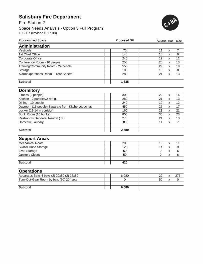
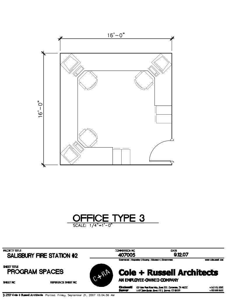
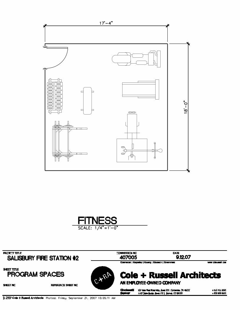
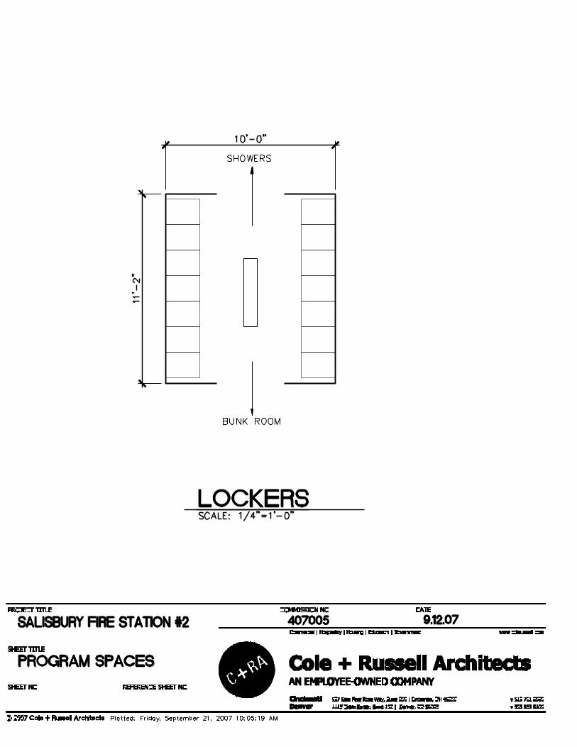
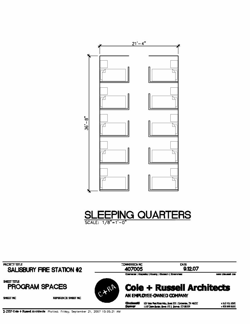
Space Needs Analysis - Option 3 Full Program10.2.07 (revised 6.17.08)
Salisbury Fire Department
Administration 1,635
Dormitory 2,580
Support Areas 420
Operations 6,080
Sub-Total SF 10,715
Infrastructure @10% 1,072
Building Circulation @12.5% 1,339
Grand Total SF 13,126 SF
Summary
40 W. Main Street, Suite #1 Phone: (717) 697-9250 Mechanicsburg, PA 17055 Fax: (717) 697-9251
January 17, 2008
Dave Johnson Cole + Russell Architects 537 East Pete Rose Way Suite 200 Cincinnati, OH 45202-3502 RE: 07081 – Salisbury Fire Station #2 Structural Evaluation Dear Dave: As requested, we performed a visual survey of Fire Station #2 in Salisbury Maryland. The purpose of the survey was to enable a preliminary evaluation of the structure to determine if it is feasible to re-use the existing structure. Enclosed is the report of our survey and evaluation. Existing Structure Observations: The existing building is comprised of three structural systems. The original part of the building is two-stories with brick load bearing walls. The other sections are one-story with masonry load bearing walls. The original building has 12” thick multi-wythe brick exterior bearing walls. One end wall has a two bay wide garage door with two windows above it. The building is approximately 28 feet wide and 72 feet long. The roof appears to have been constructed with wood trusses spanning the full building width. The brick walls extend above the roof to form parapets about three feet high on all sides. The floor is framed with 2x10 wood joists spaced at 16” on center, spanning approximately twelve feet. The floor is decked with tongue and groove planks set diagonally across the joists. The joists are supported on 10” deep steel beams that span the width of the building. The windows in the exterior side walls are centered between the locations where the beams pocket into the walls. The main garage bay is constructed of CMU bearing walls with pilasters. Wood roof trusses clear-span from the front to the rear of the garage. Currently there are two large overhead doors for the vehicles in the front wall and multiple small windows in the rear walls.
KENNETH B. ROBINSON & ASSOCIATES, CONSULTING STRUCTURAL ENGINEERS INC.
The roof between the main garage bay and original building is framed using steel joists and metal decking. The joists bear on a ledger angle lagged into the original building at one end and pocket into the CMU garage wall on the other. In general, the framing of the building sections appeared to be in good condition. The roof of the original building does not appear to have any leaks and felt sturdy. The floor was very firm and solid, and the areas that were visible were in good condition. However, the exterior brick bearing walls have a significant number of cracks through the bricks on both of the long sidewalls and at the end wall with the garage door. The quantity, size and locations of the cracks are evidence of overstressing. Cracks near the front of the original section are sizable and appear to be evidence that some settlement has occurred. The CMU bearing walls of the main garage bay also show signs of overstress. Multiple cracks were noted in the two end walls and the rear wall, especially near the pilasters. Structural Assessment: This building was evaluated with the understanding that there is the potential to reuse the structure and expand it. The plans could include additions and renovations to the original building structure. The scope of the project will be significant enough to require renovation of the existing building structures to meet the current Building Code of the County, which references the IBC. Under the IBC, this facility would be classified as a Category IV (essential) Structure. Therefore the existing structures will need to be re-evaluated for gravity and lateral load conditions. The new code requirements for construction and structural integrity are greater than those required at the time of the original building construction. In most cases of buildings the age of the original structure, the floor and roof diaphragms were not positively attached to the walls. This would need to be accomplished to meet the load path requirements of today’s standards. In addition, in many buildings of this age, lateral load resistance was not considered or was a minor consideration. Due to the important nature of the facility, these loads become significant and require a fair of amount of consideration in the design and construction. Our primary concern however, is the condition of the existing load bearing walls, especially in the original building. These cracks, as noted previously, are evidence that overstressing of the structural walls has already occurred. Repair of the cracks is most likely not simply a matter of re-pointing the masonry, but may include removing windows and toothing-in new masonry as well as adding reinforcing to the masonry work. Addition of reinforcement can be accomplished many ways, including carbon fiber-reinforced polymer (CRFP) sheets, or by making the walls thicker and adding reinforcing, by adding reinforced pilasters. Both can be costly and can potentially affect the layout of the building. Some of the cracks also are indications of settlement issues, which may or may not have been resolved. Additional testing and detailed inspections would be required, and significant costs could arise from soil stabilization if settlement remains an issue.
2 07081 – Salisbury Fire Station #2 Structural Evaluation
KENNETH B. ROBINSON & ASSOCIATES, CONSULTING STRUCTURAL ENGINEERS INC.
The conditions observed in the main garage bay raise the question whether this reasonably new addition was designed, detailed or constructed with the essential facility criteria in mind. In most cases, the requirements will necessitate additional reinforcing of walls and anchorage between the walls and roof diaphragm. These spots were not accessible for observation, nor were drawings available for review, but we believe these additional measures may not have been taken. Again, extensive effort, costs, and disruption may be incurred to ensure the renovated structure meets the applicable standards. None of the discussed considerations touched upon making the station meet the current energy requirements. This issue in itself can be difficult with solid masonry walls, requiring the walls to be firred-out to accommodate insulation, etc. Summary: Based upon the conditions observed and previously documented, we believe the existing structures will require significant reinforcement to resist the lateral loads and load path anchorage details that are now required. Modifications to the joint between the original structure and the main garage section may also be required due to the different structural systems and their geometric relationship to each other. We believe that these modifications will be cost prohibitive and could significantly limit the utilization of the facility. If you have any questions, or if we can be of further service, regarding this or any other structural issues, do not hesitate to contact us. Sincerely, Kenneth B. Robinson, PE, SECB, NSPE President Attachments: photos CC: file
3 07081 – Salisbury Fire Station #2 Structural Evaluation
KENNETH B. ROBINSON & ASSOCIATES, CONSULTING STRUCTURAL ENGINEERS INC.
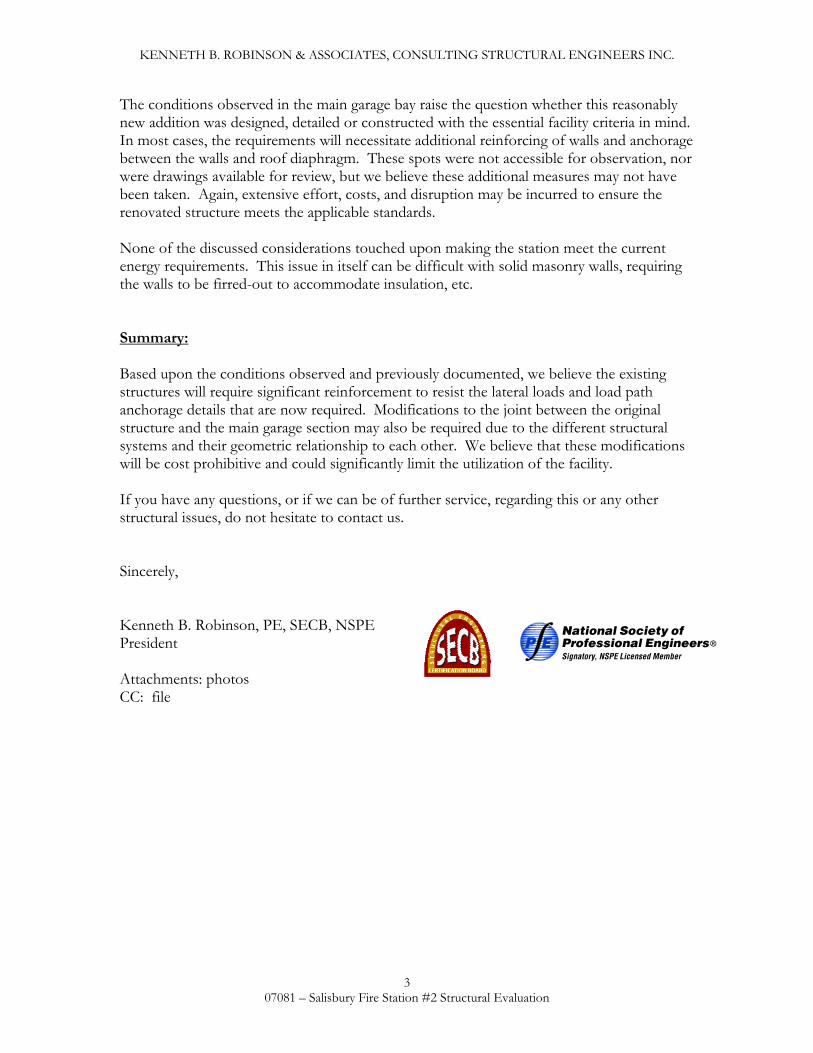
Figure 1 Front Vie w of Original Station - note cracks at windows
Figure 2 Side View of Station - not cracks at every window
4 07081 – Salisbury Fire Station #2 Structural Evaluation
KENNETH B. ROBINSON & ASSOCIATES, CONSULTING STRUCTURAL ENGINEERS INC.
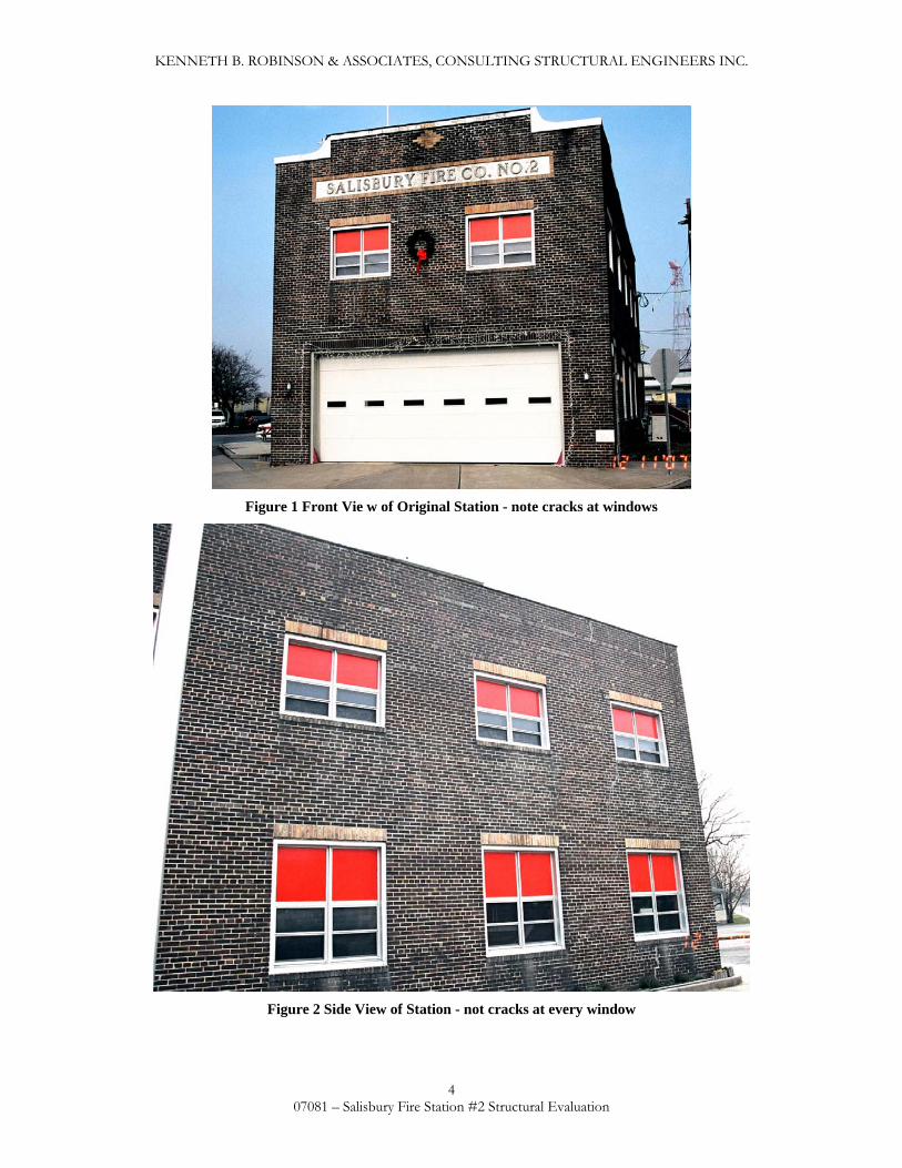
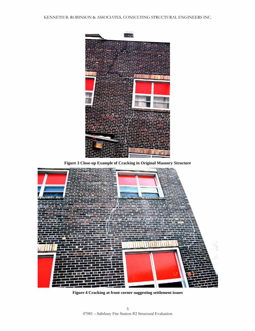
Figure 3 Close-up Example of Cracking in Original Masonry Structure
Figure 4 Cracking at front corner suggesting settlement issues
5 07081 – Salisbury Fire Station #2 Structural Evaluation
KENNETH B. ROBINSON & ASSOCIATES, CONSULTING STRUCTURAL ENGINEERS INC.
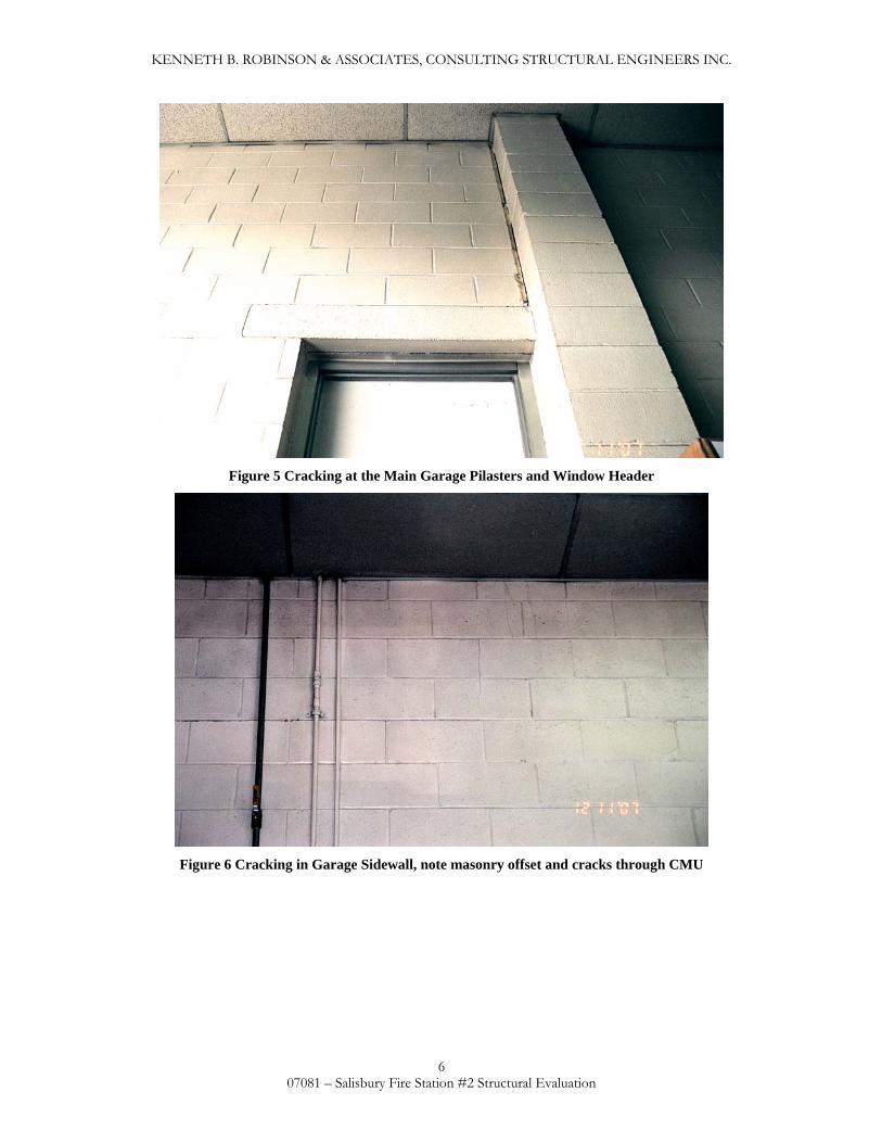
Figure 5 Cracking at the Main Garage Pilasters and Window Header
Figure 6 Cracking in Garage Sidewall, note masonry offset and cracks through CMU
6 07081 – Salisbury Fire Station #2 Structural Evaluation
KENNETH B. ROBINSON & ASSOCIATES, CONSULTING STRUCTURAL ENGINEERS INC.
Figure 7 Additional Cracking in Main Garage Sidewall
Figure 8 Cracking at Rear wall pilaster and window lintel
7 07081 – Salisbury Fire Station #2 Structural Evaluation
KENNETH B. ROBINSON & ASSOCIATES, CONSULTING STRUCTURAL ENGINEERS INC.
8 07081 – Salisbury Fire Station #2 Structural Evaluation