Page 1
Port Said University
Faculty of Engineering
Electrical Engineering Department
Port Said - Egypt
Performance Evaluation of Next Generation Wireless
Systems using Interference Alignment
A Thesis
Submitted in Partial Fulfillment of the Requirements for the Award of M.Sc.
Degree in Electrical Engineering
Electronics and Communications
Port Said University
By
Eng. Hussain Elsayed Ahmed Elkotby
B.Sc., Electrical Engineering, Faculty of Engineering,
Suez Canal University, 2009
Supervised by
Prof. Dr. Khaled Mohammed Fouad Elsayed
Electronics and Communications Department
Faculty of Engineering, Cairo University
Assoc. Prof. Mahmoud Hamed Ismail
Electronics and Communications Department
Faculty of Engineering, Cairo University
Dr. Mohammed Farouq Abdelkader
Electrical Engineering Department
Faculty of Engineering, Port Said University
2013
Page 2
Port Said University
Faculty of Engineering
Electrical Engineering Department
Port Said - Egypt
Performance Evaluation of Next Generation Wireless
Systems using Interference Alignment
A Thesis
Submitted in Partial Fulfillment of the Requirements for the Award of M.Sc.
Degree in Electrical Engineering
Electronics and Communications
Port Said University
By
Eng. Hussain Elsayed Ahmed Elkotby
B.Sc., Electrical Engineering, Faculty of Engineering,
Suez Canal University, 2009
Approved by
Prof. Dr. Said El-Sayed Esmail
El-Khamy
Electronics and Communications Department
Faculty of Engineering, Alexandria University
Prof. Dr. Khaled Mohammed Fouad
Elsayed
Electronics and Communications Department
Faculty of Engineering, Cairo University
Assoc. Prof. Dr. Atef Mohammed Ghoneim
Electrical Engineering Department
Faculty of Engineering, Port Said University
2013
Page 3
- i -
Abstract
Wireless communication systems are in continuous evolution as a result of
the ever increasing demand for higher data rate services. Examples of next
generation networks that will bring higher data rates and increase system
capacity to end users and network operators are 3GPP Long Term Evolution–
Advanced (LTE-A) and WiMAX 2. These systems are being developed under
the scope of IMT-Advanced. Recently, direct device-to-device communication
(D2D) as an underlay network to IMT-Advanced cellular networks [1] has
been proposed which represents a promising technique that is expected to
provide efficient utilization of the available wireless spectrum and is expected
to provide access to the Internet and local services using licensed bands that
can guarantee a planned environment.
Another research trend that has potential to boost the overall cellular
spectral efficiency is Interference Alignment (IA) [2]. Simply put, IA allows
signal vectors to be aligned in such a manner that they cast overlapping
shadows at the receivers where they constitute interference while they continue
to be distinct at the intended receivers [2].
In this thesis, we propose a framework for radio resource and Interference
management in D2D underlay network via Clustering and Interference
Alignment based on reusing radio resources over smaller distances. Results of
our proposal demonstrate that resource reuse over the clusters offer overall rate
increase proportional to the number of formed clusters. In addition, interference
alignment offers up to 33% increase in the overall rates in the high transmission
power regimes compared to the normal Point-to-Point (P2P) communication.
On another front, it is known that Channel state information (CSI) is crucial
for achieving reliable communication with high data rates in MIMO systems
through transmissions adaptation to current channel conditions. Usually, the
Page 4
- ii -
channel state information needs to be quantized before being fed back to the
transmitter since they will be sent over a limited-rate feedback channel. In
situations where the feedback is severely limited, a challenging issue is how to
quantize the information needed at the transmitter and then how much
improvement in the associated performance can be obtained as a function of the
amount of feedback available.
Interference alignment schemes for the K-user interference channels (ICs)
have been employed to realize the full multiplexing gain under the assumption
that CSI is ideally known at each transmitter. However, the assumption of the
perfect CSI is almost impossible to realize at the transmitters, especially for
quantized feedback systems using feedback links with finite bandwidth.
In this thesis and for the special case of 3-user IC for both SISO and MIMO
systems, we propose new strategies that aim at minimizing the quantization
error through partial processing at receivers and reduction of the amount of
feedback data to send to the transmitters. The proposed limited feedback
strategies is shown to significantly reduce the processing complexity required
for minimizing quantization errors at the receivers compared to the scheme
proposed in [3] and interestingly improves spectral efficiency performance as
well.
Page 5
- iii -
Attestation
I understand the nature of plagiarism, and I am aware of the University‘s policy on
this.
I certify that this dissertation reports original work by me during my University Master
except for the following:
The Interference Alignment (IA) overview in Chapter 2 was taken from [2],
[4].
The WINNER channel overview in Chapter 3 was taken from [5].
The Device-to-Device communication review in Chapter 4 was largely taken
from [6].
Signature Date
Page 6
- iv -
Acknowledgements
Over the past two years I have received support and encouragement from a good
number of individuals and I would like to express my gratitude to all those who gave
me the possibility to complete the work in this thesis. I am highly indebted to Prof.
Khaled El-Sayed and Dr. Mahmoud Hamed for their guidance and constant
supervision. Their help, stimulating suggestions, knowledge, experience and
encouragement helped me in all the times of study and research of this work. I am also
grateful to Dr. Mohamed Farouq for his encouragement and support in completing this
work.
Additionally, I‘d like to thank Dr. Mohamed Samy, Dr. Atef Ghonim, Dr. Ahmed
Shabaan, Dr. Khairy El Sersy, Dr. Ibrahim Hosny, Dr. Gamal Abd Al Azim, Dr.
Mohamed El Dessouki, Eng. Islam Shaalan, Eng. Rania, Eng. Heba Elsawaf, and Eng.
Nada Hussain who helped me reach this point through a large number of
undergraduate and graduate courses that shaped my current knowledge.
Moreover, I would like to express my gratitude towards my parents and fiancée for
their kind cooperation as well as for giving me the support and encouragement I
needed while working on this thesis.
―This work is part of the 4G++ project supported by the National Telecom
Regulatory Authority of Egypt‖
Page 7
- v -
List of Abbreviations
3GPP 3rd Generation Partnership Project
AWGN Additive White Gaussian Noise
BC Broadcast Channel
BER Bit Error Rate
CSI Channel State Information
D2D Device-to-Device (communication)
DoF Degrees of Freedom
FDD Frequency Division Duplex
IA Interference Alignment
IC Interference Channel
LFS Limited Feedback Scheme
LOS Line of Sight
LTE Long Term Evolution of 3GPP mobile system
MCS Modulation and Coding Scheme
MIMO Multiple Input Multiple Output
MMSE Minimum Mean Square Error
MSE Mean Square Error
NC Network Coding
NLOS Non Line of Sight
OFDM Orthogonal Frequency Division Multiplexing
OFDMA Orthogonal Frequency Division Multiple Access
PF Proportional Fairness
QoS Quality of Service
SINR Signal to Interference and Noise Ratio
SISO Single Input Single Output
SNR Signal to Noise Ratio
TDD Time Division Duplex
UE User Equipment
WiMAX Worldwide Interoperability for Microwave Access
ZF Zero Forcing
Page 8
- vi -
List of Symbols
Zero Forcing equalizer for the ith
receiver.
A
matrix containing distances between D2D users within cluster n.
𝑓 System frequency in , -
Jain’s fairness index.
gcd Channel response of the interference link from the cellular connection to the
D2D connection.
𝐇 Channel coefficients between transmitter k and receiver j.
𝐇
Channel between pair 𝑗 transmitter in cluster 𝑙 and pair 𝑖 receiver in cluster 𝑛.
Number of channel extensions or number of antennas.
Number of D2D users in the cell.
Number of D2D pairs in the cell.
Number of RBs dedicated to D2D users.
Number of Clusters.
Number of D2D pairs per cluster.
Number of IA groups.
Power allocated to the cellular link.
Power allocated to the D2D link.
Available power at the ith
transmitter.
Distance dependent path loss.
Maximum power that can be allocated to a user.
Sum rate for Non-Orthogonal Sharing (NOS) of the resources.
𝐔 Interference suppression matrix for the ith
receiver.
𝐕 IA precoder designed by Douglas and Murat in [32] for user 𝑖.
Vector of transmitted symbols at the ith
transmitter.
Throughput for the ith
user.
Additive white Gaussian noise at the ith
receiver.
Selection variable that indicates the allocation of RB 𝑘 for pair 𝑖 in cluster 𝑛.
SINR needed for using the highest MCS.
Guaranteed SINR to prioritize the cellular connection.
IA precoder designed by Cadambe and Jafar in [2] for user 𝑖.
Zero-mean Gaussian distributed random variable with standard deviation .
Degrees of freedom available for the pair 𝑖.
Page 9
- vii -
Table of Contents
Abstract ...................................................................................................................... i
Attestation ................................................................................................................ iii
Acknowledgements .................................................................................................. iv
List of Abbreviations................................................................................................. v
List of Symbols ........................................................................................................ vi
Table of Contents .................................................................................................... vii
List of Publications .................................................................................................. xi
List of Figures ......................................................................................................... xii
1 Introduction .......................................................................................................... 1
1.1 Wireless Standards Evolution ...................................................................... 1
1.2 4G Requirements and Solution Proposals .................................................... 3
1.2.1 Carrier Aggregation ................................................................................ 5
1.2.2 Coordinated multipoint transmission and reception (CoMP) ................. 9
1.2.3 Relays.................................................................................................... 10
1.2.4 Heterogeneous Networks ...................................................................... 11
1.2.5 Key Technologies for Rel-12 and Beyond ............................................ 11
1.3 Thesis Background and Context ................................................................ 12
1.4 Thesis Overview and Organization ............................................................ 15
2 Interference Alignment Overview ...................................................................... 18
2.1 Introduction ................................................................................................ 18
2.2 Interference Alignment in Different Wireless Channels ............................ 19
2.2.1 The Wireless X Network ....................................................................... 19
2.2.1.1 Wireless X Network with Single-Antenna Nodes ......................... 21
2.2.1.2 Wireless X Network with Multiple-Antenna Nodes ...................... 21
2.2.2 The K-User Interference Channel ......................................................... 22
2.2.2.1 K-User Interference Channel with Single Antenna Nodes ............ 24
2.2.2.2 The K-User Interference Channel with Multiple Antenna Nodes . 25
2.3 Summary .................................................................................................... 26
3 Background on System and Channel Models ..................................................... 27
Page 10
- viii -
3.1 Introduction ................................................................................................ 27
3.2 Basic Properties of Wireless Channels ....................................................... 28
3.2.1 Distance-Dependent Path Loss ............................................................. 29
3.2.2 Shadow Fading ..................................................................................... 30
3.2.3 Multipath Fading ................................................................................... 30
3.3 Channel Model ........................................................................................... 31
3.4 WINNER Channel Model Overview ......................................................... 32
3.4.1 Coordinate Systems in WIM2 ............................................................... 34
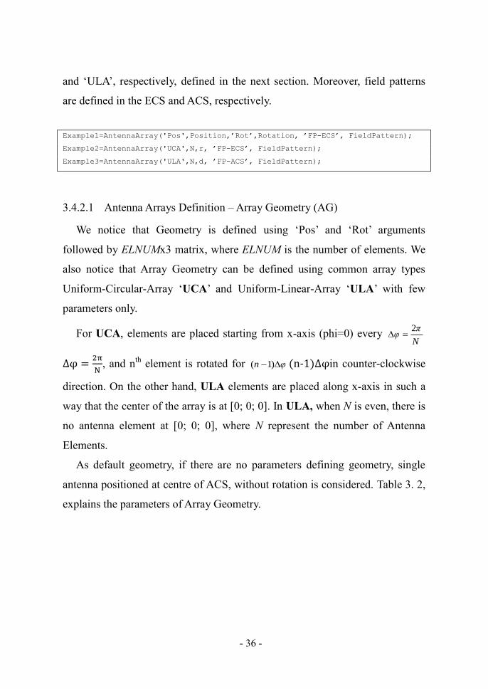
3.4.2 Antenna Arrays Definition and Construction........................................ 35
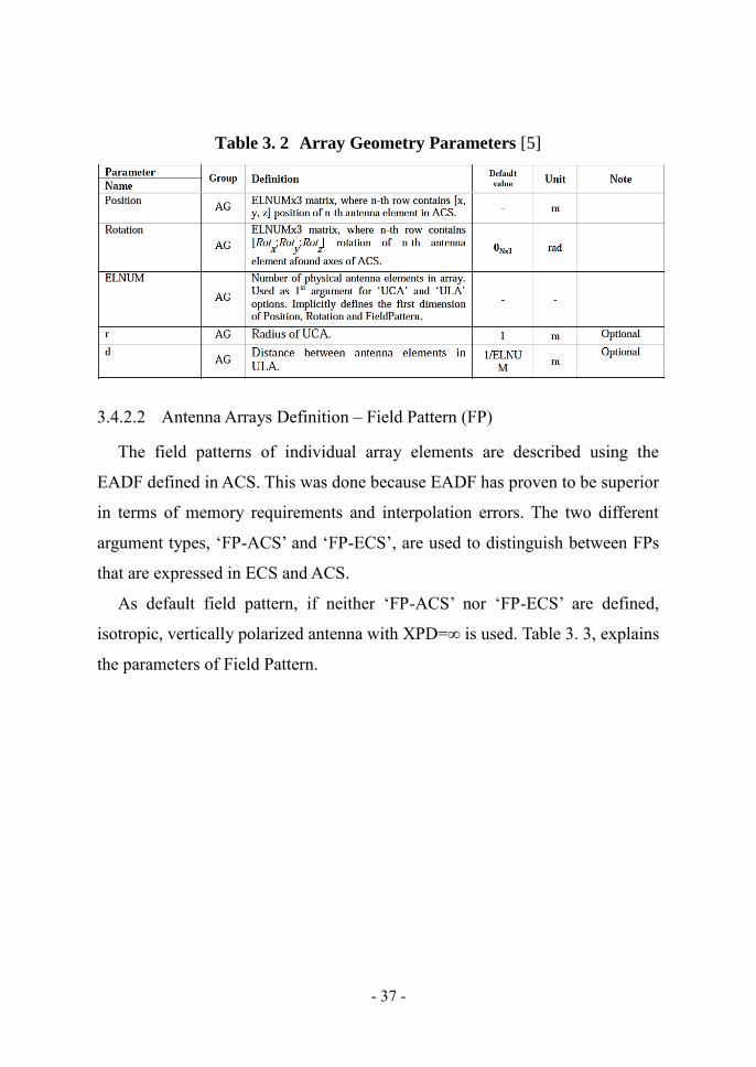
3.4.2.1 Antenna Arrays Definition – Array Geometry (AG) ..................... 36
3.4.2.2 Antenna Arrays Definition – Field Pattern (FP) ............................ 37
3.4.2.3 Arrays Construction Examples...................................................... 38
3.4.3 System Level Layout Design ................................................................ 39
3.4.3.1 Construction of Semi-Random Layout ......................................... 39
3.4.3.2 Layout Manual Editing.................................................................. 40
3.4.4 WIM2 Model Input and Output Parameters ......................................... 43
3.4.4.1 Initialization of the Structural Model Parameters ......................... 44
3.4.4.2 WIM2 Model Output ..................................................................... 44
3.4.4.3 OFDM Channel Outputs ............................................................... 45
3.4.4.4 Sample Output ............................................................................... 46
4 Device-to-Device Communication underlay in Cellular Networks ................... 48
4.1 Introduction ................................................................................................ 48
4.2 Coexistence of Cellular and Ad Hoc Networks ......................................... 50
4.3 New Local Services with D2D Communication ........................................ 51
4.4 Cooperative Transmission Through Network Coding................................ 52
4.4.1 Network Coding .................................................................................... 53
4.4.2 User Grouping ....................................................................................... 54
4.5 Interference Coordination in a D2D Enabled Cellular Network ................ 55
4.5.1 D2D Communication with Full CSI ..................................................... 57
4.5.2 D2D Communication with Limited CSI ............................................... 60
5 Radio Resource and Interference Management in D2D Underlay via Clustering
and Interference Alignment ................................................................................ 63
Page 11
- ix -
5.1 Introduction ................................................................................................ 64
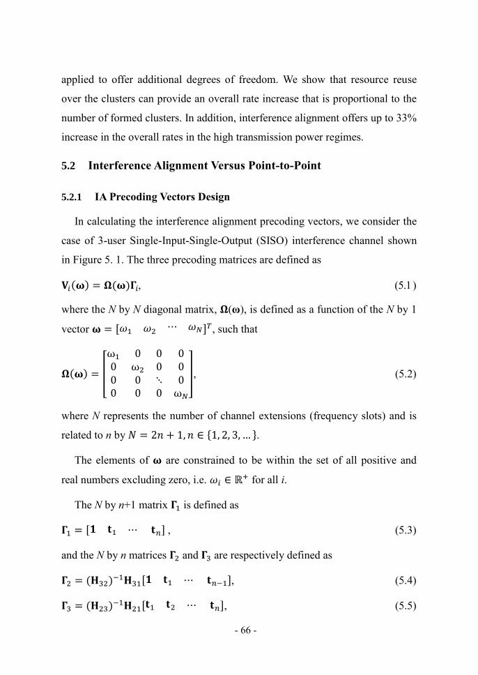
5.2 Interference Alignment Versus Point-to-Point ........................................... 66
5.2.1 IA Precoding Vectors Design ................................................................ 66
5.2.2 Receiver Design for the P2P and IA Models ........................................ 67
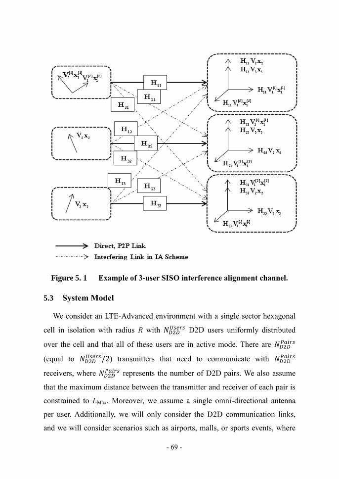
5.3 System Model ............................................................................................ 69
5.4 Fuzzy Clustering Schemes ......................................................................... 73
5.4.1 The D2D Clusters Formation ................................................................ 74
5.4.2 The IA Group Formation in Each Cluster ............................................. 75
5.4.2.1 Position-Based Grouping Scheme (PBS) ...................................... 76
5.4.2.2 Channel-Based Grouping Scheme (CBS) ..................................... 77
5.4.2.3 Distance-Based Grouping Scheme (DBS) .................................... 77
5.5 The Proposed IA-based Transmission and the Associated Resource Block
Allocation Scheme ..................................................................................... 78
5.5.1 The Overall D2D IA-Based Transmission Scheme .............................. 79
5.5.2 Resource Block Allocation for the D2D Links ..................................... 79
5.6 Performance Evaluation ............................................................................. 81
5.6.1 Point-to-Point vs. Interference Alignment ............................................ 81
5.6.2 System Level Results ............................................................................ 82
5.6.2.1 Single Cluster Per Cell .................................................................. 83
5.6.2.2 Multiple Clusters Per Cell ............................................................. 84
6 Low-Complexity Limited Feedback Strategy in 3-User Interference Channel
Exploiting Interference Alignment ..................................................................... 92
6.1 Introduction ................................................................................................ 92
6.2 System Description and Background ......................................................... 95
6.3 Previous Work ............................................................................................ 98
6.4 Low-Complexity Limited Feedback Strategy in a 3-User Interference
Alignment System ...................................................................................... 99
6.4.1 Quantization over Composite Grassmann Manifold (CS) .................... 99
6.4.2 Limited Feedback Through Receive Channel Transformation (RCT) 102
6.4.3 Closed Form Solution for Interference Alignment ............................. 104
6.4.4 Proposed Limited Feedback Strategies ............................................... 105
Page 12
- x -
6.4.4.1 Proposed Limited Feedback Strategies for the 3-User SISO
Channel ....................................................................................... 105
6.4.4.2 Proposed Limited Feedback Strategies for the 3-User MIMO
Channel (PRP-MIMO) ................................................................ 107
6.5 Performance Evaluation ........................................................................... 108
7 Conclusion ........................................................................................................ 111
7.1 Evaluation ................................................................................................ 111
7.2 Future Work ............................................................................................. 112
References ............................................................................................................. 113
Page 13
- xi -
List of Publications
This thesis consists of an overview and of the following publications.
I. H. E. Elkotby, K. M. F. Elsayed, and M. H. Ismail, ―Exploiting interference
alignment for sum rate enhancement in D2D-enabled cellular networks,‖ in Proc.
of the IEEE Wireless Communications and Networking Conference (WCNC 2012),
Paris, France, Apr. 2012.
II. H. E. Elkotby, K. M. F. Elsayed, and M. H. Ismail, ―Shrinking the reuse distance:
Spectrally-efficient radio resource management in D2D-enabled cellular networks
with interference alignment,‖ in Proc. of the IFIP Wireless Days (WD' 2012),
Dublin, Ireland, November 2012.
III. H. E. Elkotby, K. M. F. Elsayed, and M. H. Ismail, ―Low-complexity limited
feedback strategies in a 3-user interference channel exploiting interference
alignment,‖ – submitted.
Page 14
- xii -
List of Figures
Figure 1. 1 Carrier aggregation in contiguous bandwidth (Intra-band, contiguous). .. 7
Figure 1. 2 Carrier aggregation in non-contiguous bandwidth, single band (Intra-
band, non-contiguous). ............................................................................. 8
Figure 1. 3 Carrier aggregation in non-contiguous bandwidth, multiple bands (Inter-
band, non-contiguous). ............................................................................. 8
Figure 2. 1 An Example 2 2 user X network Channel. ......................................... 21
Figure 2. 2 An Example 3-user Interference Channel. .............................................. 23
Figure 3. 1 A cellular network with D2D and Relaying Concept ............................. 28
Figure 3. 2 System Level Approach [5]. ................................................................... 34
Figure 3. 3 Relations between Coordinate Systems [5]. ........................................... 35
Figure 3. 4 Manual Edited Example Layout Virtualization. ..................................... 43
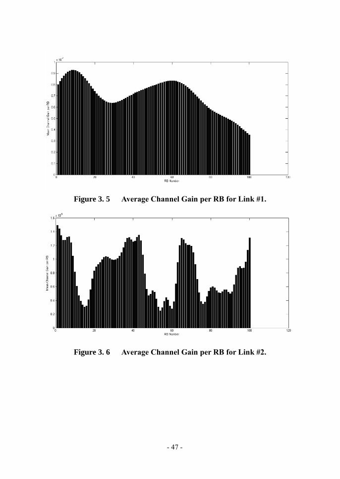
Figure 3. 5 Average Channel Gain per RB for Link #1............................................. 47
Figure 3. 6 Average Channel Gain per RB for Link #2............................................. 47
Figure 4. 1 D2D communication works as an underlay to a cellular network. ......... 50
Figure 4. 2 Proposed two-user cooperative networks in [38]. ................................... 54
Figure 4. 3 Illustration of direct and interfering links in a D2D enabled cellular
network. .................................................................................................. 59
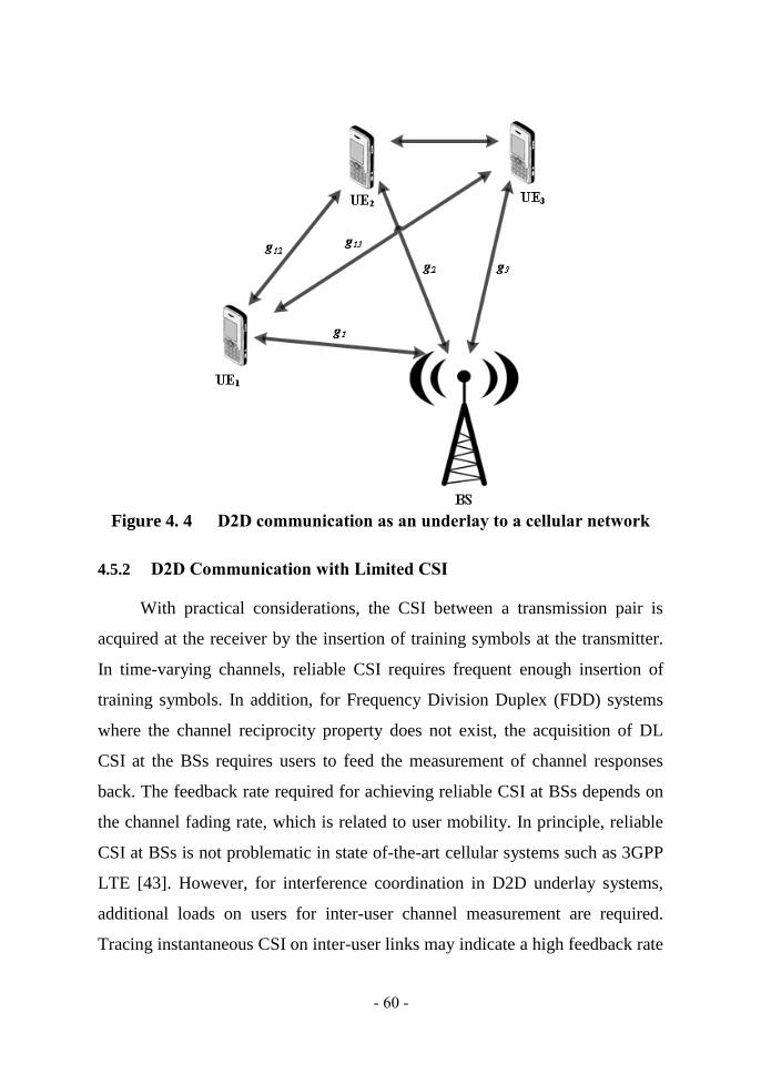
Figure 4. 4 D2D communication as an underlay to a cellular network ..................... 60
Figure 4. 5 System settings in [44]. ........................................................................... 62
Figure 5. 1 Example of 3-user SISO interference alignment channel. ...................... 69
Figure 5. 2 An illustrative example on the clustering and IA grouping steps. .......... 72
Figure 5. 3 Fuzzy C-Means Clustering Algorithm .................................................... 76
Figure 5. 4 The DBS Grouping Algorithm ................................................................ 78
Figure 5. 5 BER comparison between traditional P2P transmission and IA
transmission using a) CJ scheme. b) DM scheme. .................................. 85
Figure 5. 6 Sum rate comparison between traditional P2P transmission and IA
transmission using a) CJ scheme. b) DM scheme. .................................. 86
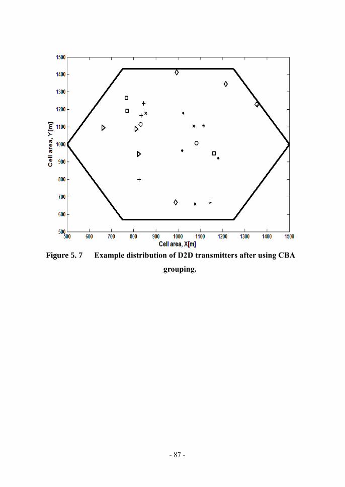
Figure 5. 7 Example distribution of D2D transmitters after using CBA grouping. ... 87
Figure 5. 8 Example distribution of D2D transmitters after using DBA grouping. .. 88
Page 15
- xiii -
Figure 5. 9 Total sum rate of a single cell enabling D2D communication for both P2P
and IA transmission. ............................................................................... 89
Figure 5. 10 Fairness index results for both P2P and IA transmission when using a)
CBS. b) DBS. c) PBS.............................................................................. 89
Figure 5. 11 Total sum rate of a single cell enabling D2D communication with IA
transmission for different cluster sizes.................................................... 90
Figure 5. 12 Total sum rate of a single cell enabling D2D communication with IA
transmission for different cluster sizes normalized by the number of
clusters . ............................................................................................ 90
Figure 5. 13 Comparing total sum rate per cluster for greedy and proportional fair
resources allocation. ................................................................................ 91
Figure 5. 14 Comparing fairness index for greedy and proportional fair resources
allocation. ................................................................................................ 91
Figure 6. 1 K-User Interference Channel with Direct and Interfering Links
Clarification. ........................................................................................... 97
Figure 6. 2 3-User Interference Channel. .................................................................. 98
Figure 6. 3 Spectral efficiency results in case of SISO, 𝐵 = 4, and = 3. .......... 109
Figure 6. 4 Spectral efficiency results in case of MIMO, 𝐵 = 4, and = 2. ....... 109
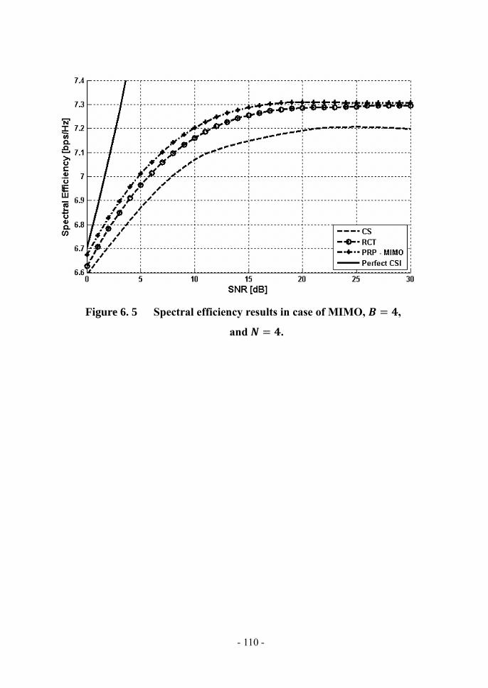
Figure 6. 5 Spectral efficiency results in case of MIMO, 𝐵 = 4, and = 4. ....... 110
Page 16
- 1 -
1 Introduction
Wireless communication systems are in continuous evolution as a result of
the ever increasing demand for higher data rate services. Examples of next
generation networks that will bring higher data rates and increase system
capacity to end users and network operators are 3GPP Long Term Evolution –
Advanced (LTE-A) and WiMAX 2. These systems are being developed under
the scope of IMT-Advanced. Recently, direct device-to-device communication
(D2D) as an underlay network to IMT-Advanced cellular networks has been
proposed as a promising technique that is expected to provide efficient
utilization of the available wireless spectrum. Moreover, Interference
Alignment (IA) has shown the potential to boost the overall cellular spectral
efficiency. In this thesis, we study the potential of deploying D2D
communication as an underlay in cellular networks and the benefits of
exploiting IA in this setup.
1.1 Wireless Standards Evolution
Mobile communications have grown very rapidly since its invention. The
first generation (1G) system was designed only for voice communication using
the analog circuit switched networks. The second generation (2G) system,
which first introduced digital cellular technology, was established to provide
voice communication as well as data communication but with very low data
rates. However, the need for new data services derived operators to introduce
the 2.5 G system to increase data rates first to 56 kbps, and then up to 114 kbps.
Global System for Mobile Communications (GSM) Enhanced Data Rates for
Global Evolution (EDGE) provided further enhancements to the data rates in
the 2G systems of up to 236.8 kbps.
Page 17
- 2 -
Wireless communications have evolved from the 2G systems through the
deployment of third generation (3G) systems with their higher speed data
networks to the much-anticipated fourth generation technology being
developed today. Early 3G systems did not immediately meet the ITU 2 Mbps
peak data rate targets in practical deployment although they did in theory.
However, there have been improvements to the standards since then that have
brought deployed systems closer to and now well beyond the original 3G
targets. It is notable that fewer standards are being proposed for 4G than in
previous generations, with only two 4G candidates being actively developed
today: 3GPP LTE-Advanced and IEEE 802.16m, which is the evolution of the
WiMAX standard known as Mobile WiMAX 2. The process for 4G started
with 3GPP LTE and IEEE 802.16e being the two candidates introduced. Later,
these two became known as 3.9G since they could not satisfy all the
requirements for 4G systems.
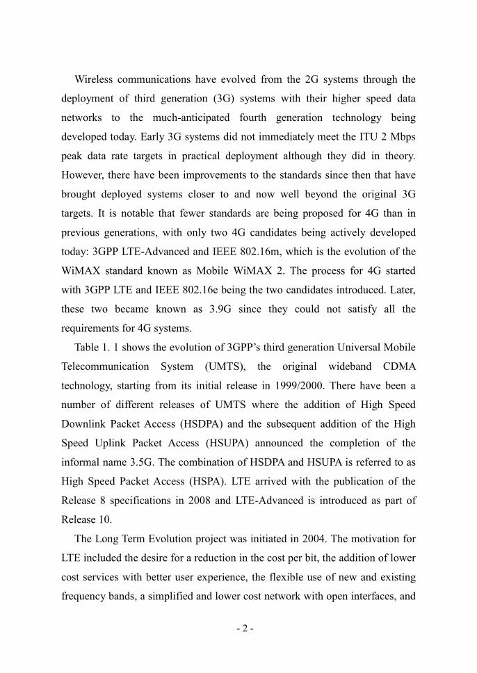
Table 1. 1 shows the evolution of 3GPP‘s third generation Universal Mobile
Telecommunication System (UMTS), the original wideband CDMA
technology, starting from its initial release in 1999/2000. There have been a
number of different releases of UMTS where the addition of High Speed
Downlink Packet Access (HSDPA) and the subsequent addition of the High
Speed Uplink Packet Access (HSUPA) announced the completion of the
informal name 3.5G. The combination of HSDPA and HSUPA is referred to as
High Speed Packet Access (HSPA). LTE arrived with the publication of the
Release 8 specifications in 2008 and LTE-Advanced is introduced as part of
Release 10.
The Long Term Evolution project was initiated in 2004. The motivation for
LTE included the desire for a reduction in the cost per bit, the addition of lower
cost services with better user experience, the flexible use of new and existing
frequency bands, a simplified and lower cost network with open interfaces, and
Page 18
- 3 -
a reduction in terminal complexity with an allowance for reasonable power
consumption.
These high level goals led to further expectations for LTE, including
reduced latency for packets, and spectral efficiency improvements above
Release 6 high speed packet access (HSPA) of three to four times in the
downlink and two to three times in the uplink. Flexible channel bandwidths—a
key feature of LTE—are specified at 1.4, 3, 5, 10, 15, and 20 MHz in both the
uplink and the downlink. This allows LTE to be flexibly deployed where other
systems exist today, including narrowband systems such as GSM.
Table 1. 1 Evolution of UMTS specifications [7]
Release Functional
Freeze
Main Radio Features of the Release
Rel-99 March 2000 UMTS 3.84 Mcps (W-CDMA FDD & TDD)
Rel-4 March 2001 1.28 Mcps TDD (aka TD-SCDMA)
Rel-5 June 2002 HSDPA
Rel-6 March 2005 HSUPA (E-DCH)
Rel-7 Dec 2007 HSPA+ (64QAM DL, MIMO, 16QAM UL), LTE & SAE
Rel-8 Dec 2008 LTE work item – OFDMA air interface, SAE work item, new
IP core network, 3G femtocells, dual carrier HSDPA
Rel-9 Dec 2009 Multi-standard radio (MSR), dual cell HSUPA
LTE-Advanced feasibility study, SON, LTE femtocells
Rel-10 March 2011 LTE-Advanced (4G) work item, CoMP study, four carrier
HSDPA
1.2 4G Requirements and Solution Proposals
The third generation of cellular radio technology was defined by the ITU-R
through the International Mobile Telecommunications 2000 project (IMT-
2000). The requirements for IMT-2000, defined in 1997, were expressed only
in terms of peak user data rates:
Page 19
- 4 -
• 2048 kbps for indoor office.
• 384 kbps for outdoor to indoor and pedestrian environments.
• 144 kbps for vehicular connections.
• 9.6 kbps for satellite connections.
Of significance is that there was no requirement defined for spectral
efficiency in 3G. The situation is quite different for IMT-Advanced.
The ITU‘s high level requirements for IMT-Advanced include the following
[7]:
• A high degree of common functionality worldwide while retaining the
flexibility to support a wide range of local services and applications in a
cost-efficient manner.
• Compatibility of services within IMT and with fixed networks.
• Capability for interworking with other radio systems.
• High quality mobile services.
• User equipment suitable for worldwide use.
• User-friendly applications, services, and equipment.
• Worldwide roaming capability.
• Enhanced peak data rates to support advanced mobile services and
applications (in the downlink, 100 Mbps for high mobility and 1 Gbps
for low mobility).
For the most part these are general purpose requirements that any good
standard would attempt to achieve. The key requirement that sets 4G apart from
previous standards is reflected in the last item, which gives the expectations for
peak data rates that reach as high 1 Gbps for low mobility applications and 100
Mbps for high mobility. This is a huge increase from 3G, which specified a
peak rate of 2 Mbps for indoor low mobility applications and 144 kbps
vehicular. The peak rates targeted for 4G will have fundamental repercussions
on system design.
In the feasibility study for LTE-Advanced, 3GPP determined that LTE-
Advanced would meet the ITU-R requirements for 4G. Further, it was
determined that 3GPP Release 8 LTE could meet most of the 4G requirements
Page 20
- 5 -
apart from uplink spectral efficiency and the peak data rates. From a link
performance perspective, LTE already achieves data rates very close to the
Shannon limit, which means that the main effort must be made in the direction
of improving the Signal-to-Interference-and-Noise Ratio (SINR) experienced
by the users and hence provide data rates over a larger portion of the cell [8].
These higher requirements are addressed with the addition of the following
LTE-Advanced features [7]:
• Wider bandwidths, enabled by carrier aggregation.
• Higher efficiency, enabled by enhanced uplink multiple access and
enhanced multiple antenna transmission (advanced MIMO techniques).
Other performance enhancements are under consideration for Release 10
and beyond, even though they are not critical to meeting 4G requirements:
• Coordinated multipoint transmission and reception (CoMP).
• Relaying.
• Support for heterogeneous networks.
• LTE self-optimizing network (SON) enhancements.
• Home enhanced-node-B (HeNB) mobility enhancements.
• Fixed wireless customer premises equipment (CPE) RF requirements.
1.2.1 Carrier Aggregation
Achieving the 4G target downlink peak data rate of 1 Gbps will require
wider channel bandwidths than are currently specified in LTE Release 8. At the
moment, LTE supports channel bandwidths up to 20 MHz, and it is unlikely
that spectral efficiency can be improved much beyond current LTE
performance targets. Therefore the only way to achieve significantly higher
data rates is to increase the channel bandwidth. IMT-Advanced sets the upper
limit at 100 MHz, with 40 MHz the expectation for minimum performance. In
order for LTE-Advanced to fully utilize the wider bandwidths of up to 100
MHz, while keeping backward compatibility with LTE, a carrier aggregation
scheme has been proposed. Carrier aggregation consists of grouping several
Page 21
- 6 -
LTE ‗‗component carriers‘‘ (CCs) (e.g. of up to 20 MHz), so that the LTE-
Advanced devices are able to use a greater amount of bandwidth (e.g. up to 100
MHz), while at the same time allowing LTE devices to continue viewing the
spectrum as separate component carriers. Additionally, in order to meet the
requirements of IMT-Advanced as well as those of 3GPP operators, LTE-
Advanced considers the use of bandwidths in the following spectrum bands (in
addition to those already allocated for LTE) [8]:
• 450–470 MHz band (identified in WRC-07 to be used globally for IMT
systems).
• 698–862 MHz band (identified in WRC-07 to be used in Region 22 and
nine countries of Region 3).
• 790–862 MHz band (identified in WRC-07 to be used in Regions 1 and
3).
• 2.3–2.4 GHz band (identified in WRC-07 to be used globally for IMT
systems).
• 3.4–4.2 GHz band (3.4–3.6 GHz identified in WRC-07 to be used in a
large number of countries).
• 4.4–4.99 GHz band.
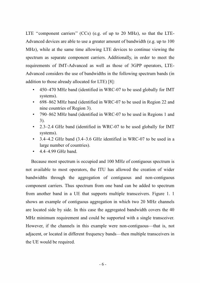
Because most spectrum is occupied and 100 MHz of contiguous spectrum is
not available to most operators, the ITU has allowed the creation of wider
bandwidths through the aggregation of contiguous and non-contiguous
component carriers. Thus spectrum from one band can be added to spectrum
from another band in a UE that supports multiple transceivers. Figure 1. 1
shows an example of contiguous aggregation in which two 20 MHz channels
are located side by side. In this case the aggregated bandwidth covers the 40
MHz minimum requirement and could be supported with a single transceiver.
However, if the channels in this example were non-contiguous—that is, not
adjacent, or located in different frequency bands—then multiple transceivers in
the UE would be required.
Page 22
- 7 -
The term component carrier used in this context refers to any of the
bandwidths defined in Release 8/9 LTE. To meet ITU 4G requirements, LTE-
Advanced will support three component carrier aggregation scenarios: intra-
band contiguous, intra-band non-contiguous, and inter-band non-contiguous
aggregation. The spacing between center frequencies of contiguously
aggregated component carriers will be a multiple of 300 kHz to be compatible
with the 100 kHz frequency raster of Release 8/9 and at the same time preserve
orthogonality of the subcarriers, which have 15 kHz spacing. Depending on the
aggregation scenario, the n x 300 kHz spacing can be facilitated by inserting a
low number of unused subcarriers between contiguous component carriers. In
the case of contiguous aggregation, more use of the gap between component
carriers could be made, but this would require defining new, slightly wider
component carriers.
Figure 1. 1 Carrier aggregation in contiguous bandwidth (Intra-band,
contiguous).
Page 23
- 8 -
Figure 1. 2 Carrier aggregation in non-contiguous bandwidth, single
band (Intra-band, non-contiguous).
Figure 1. 3 Carrier aggregation in non-contiguous bandwidth, multiple
bands (Inter-band, non-contiguous).
An LTE-Advanced UE with capabilities for receive and/or transmit carrier
aggregation will be able to simultaneously receive and/or transmit on multiple
component carriers. A Release 8 or 9 UE, however, can receive and transmit on
a single component carrier only. Component carriers must be compatible with
LTE Release 8 and 9.
In Release 10, the maximum size of a single component carrier is limited to
110 resource blocks, although for reasons of simplicity and backwards
Page 24
- 9 -
compatibility it is unlikely that anything beyond the current 100 RB will be
specified. Up to 5 component carriers may be aggregated. An LTE-Advanced
UE cannot be configured with more uplink component carriers than downlink
component carriers, and in typical TDD deployments the number of uplink and
downlink component carriers, as well as the bandwidth of each, must be the
same. More details about carrier aggregation are available in [7–9].
1.2.2 Coordinated multipoint transmission and reception (CoMP)
Cooperative Multipoint (CoMP) transmission and reception is a framework
that refers to a system where several geographically distributed antenna nodes
cooperate with the aim of improving the performance of the users served in the
common cooperation area. Multiple eNBs may cooperate to determine the
scheduling, transmission parameters, and transmit antenna weights for a
particular UE. This cooperation will depend on a high-capacity backhaul link
being available between eNBs. The objective of CoMP is to reduce interference
for a UE set in the network that is close to multiple eNBs and therefore
experiences an interference-limited environment. The interference to these UE
sets may be reduced and can be predicted if there is some coordination between
the interfering eNBs and the serving eNB.
CoMP techniques are being studied for both the downlink and the uplink
transmission paths. In the downlink, two main CoMP transmission techniques
are envisioned: cooperative scheduling/beamforming and joint processing.
Their main difference lies in the fact that in the former scheme it is only one
eNB that transmits data to the UE, although different eNBs may share control
information. In the latter scheme, many eNBs transmit data simultaneously to
the same UE. In the uplink, however, only a coordinated scheduling approach
is envisioned. Coordinated multipoint will be studied further for 3GPP Release
11, [7–10].
Page 25
- 10 -
1.2.3 Relays
LTE-Advanced is considering relaying for cost-effective throughput
enhancement and coverage extension. The use of relays will allow the
following improvements [8]:
• Coverage extension in rural areas.
• Temporary network deployment.
• Cell-edge throughput improvement.
• Urban or indoor throughput enhancement.
These improvements can be grouped as ‗‗coverage extension‘‘ and
‗‗throughput enhancement‘‘. A relay node (RN) is connected wirelessly to the
radio access network via a donor cell. In the proposals for Release 10, the RN
will connect to the donor cell‘s eNB (DeNB) in one of two ways [7]:
• In-band (in-channel), in which case the DeNB-to-RN link shares the
same carrier frequency with RN-to-UE links.
• Out-band, in which case the DeNB-to-RN link does not operate in the
same carrier frequency as RN-to-UE links.
Relays can be classified according to the layers in which their main
functionality is performed as:
• A Layer 1 (L1) relay (Amplify and Forward) is also called a repeater. It
takes the received signal, amplifies it and forwards it to the next hop.
• A Layer 2 (L2) relay (Decode and Forward) works up to the Medium
Access Control (MAC) and Radio Link Control (RLC) layers, which
enables the relay to decode transmissions before retransmitting them
and thus minimize the interference created by Amplify and Forward
relays.
• A Layer 3 (L3) or higher-layer relay can be thought of as a wireless
eNB that uses a wireless link for backhaul instead of a wired and
expensive link.
Effect of relaying on coverage and capacity has been discussed in [11–13].
The concept of dynamic relaying is proposed in [14]. More details about
relaying can be found in [7], [8], [10], [15–17].
Page 26
- 11 -
1.2.4 Heterogeneous Networks
In heterogeneous networks (HetNets) low-power nodes are distributed
throughout macrocell networks. Lowpower nodes can be micro eNBs, pico
eNBs, home eNBs (HeNBs, for femtocells), relays, and distributed antenna
systems (DASs). These types of cells operate in low-geometry environments
and produce high interference conditions. Such deployments enable
optimization of network performance at relatively low cost.
As the network becomes more complex, the subject of radio resource
management is growing in importance. Work is ongoing to develop more
advanced methods of radio resource management including new self-
optimizing network (SON) features. Additionally, CoMP and intercell
interference coordination (ICIC) techniques can play a critical role in obtaining
good performance within heterogeneous deployments. Further information on
heterogeneous and femtocell networks can be found in [7], [18–21].
1.2.5 Key Technologies for Rel-12 and Beyond
The biggest challenge facing mobile operators and their technology
suppliers is in satisfying the exponential growth in data traffic. LTE networks
are already providing headline speeds approaching 100 Mbps, but these are
only possible under ideal conditions on lightly loaded networks and where user
equipment is close to the base station radio antenna. Many technologies and
features introduced in previous releases are being enhanced and supplemented
with new additions in Releases 12 and 13. The following relevant candidate
technologies has been identified [22]:
• Vertical and 3D beamforming.
• Relay Backhaul Enhancement.
• Enhanced MDT (Minimization of Drive Tests).
Page 27
- 12 -
New licensed bands, including higher frequencies for hot-spot demand
zones will be introduced. This will be used in combination with unlicensed
spectrum, if suitable, while possibly exploiting cognitive radio techniques to
access and manage the latter.
Vertical and 3D beamforming techniques can mitigate inter-cell interference
more effectively even without inter-eNB coordination. Moreover, massive
antenna beamforming with arrays of as many as 64 antenna elements will
enable additional frequency reuse within cell sectors. Beamforming can utilize
the vertical domain by vertical sectorization, reaching capacity improvement
over the traditional sectorization solution [23].
The MDT is expected to be enhanced so as to collect sufficient information
for knowing e.g. following aspects to further reduce operators‘ OPEX [22]:
• User perceived QoS at boundary of LTE and UMTS cell.
• Coverage problems caused by Closed Subscriber Group (CSG) cells.
• Altitude information when UE locates indoor.
• Inter Radio Access Technology (RAT) interference on the same
frequency.
Moreover, Radio technologies and frequency bands focusing on LTE are
expected to develop new solutions for public safety uses and proximity services
(device-to-device, D2D) to overcome interoperability problems among
different emergency service providers. Resilience to earthquake, tsunami and
hurricane are increasingly important for public safety users. So, while D2D
complies with LTE-based standardized technologies, it can still become pretty
useful if the network has been wiped out in a natural disaster [24].
1.3 Thesis Background and Context
Recently, direct D2D communication as an underlay network to IMT-
Advanced cellular networks [1] has been proposed. D2D represents a
promising technique that is expected to provide efficient utilization of the
Page 28
- 13 -
available wireless spectrum. Moreover, this technique has also been proposed
as a new technology component for LTE-Advanced that is expected to provide
access to the Internet and local services using licensed bands that can guarantee
a planned environment. In comparison, unlicensed spectrum operation of
Bluetooth and WLAN causes uncertainty as to whether the spectrum and
services are truly available.
D2D current research areas include the study of D2D communication and
cellular users interference, which are discussed in [1] and [25], where a power
control optimization and coordination mechanism is used. The concept behind
this coordination mechanism is to select one of four different resource
allocation modes; downlink resource sharing, uplink resource sharing, separate
resource sharing and conventional cellular system mode. Results in [1] show
that by properly defining the maximum power on the D2D link, a good D2D
link signal-to-interference-plus-noise ratio (SINR) is achieved while at the
same time the impact on the cellular network is minor. Additionally, The results
in [1] show that significant gains in the sum rate can be achieved by enabling
D2D communications compared to the conventional cellular system. Necessary
additions to an LTE-Advanced network to enable D2D session setup and
management are proposed in [26]. In [27], a study of the potential D2D
communication gains when used as an underlay to the downlink of a cellular
network is presented where it is shown that multi-antenna receivers are
required to achieve sufficient signal-to-interference-plus-noise ratios (SINRs)
that allow D2D communication when D2D connections share the same cellular
resources.
Another research trend that has potential to boost the overall cellular
spectral efficiency is Interference Alignment (IA) [6]. Simply put, IA allows
signal vectors to be aligned in such a manner that they cast overlapping
shadows at the receivers where they constitute interference while they continue
Page 29
- 14 -
to be distinct at the intended receivers [2]. Using IA, the interference channel is
shown not to be essentially interference limited. IA offers the wireless
interference channel with K transmitter–receiver pairs the ability to
simultaneously provide each user the opportunity to send at a data rate equal to
half of his interference-free channel capacity to his desired receiver, even
though the number of users K can be arbitrarily large. Cadambe and Jafar (CJ)
[2] have shown that the achievable degrees of freedom are bounded by the
number of symbol extensions, and it is possible to achieve K/2 degrees of
freedom per orthogonal time and frequency dimension as the number of
channel extensions reaches infinity. This result allows the degrees of freedom
to grow linearly with the number of users without cooperation in the form of
message sharing thus allowing MIMO behavior. IA requires coding over
multiple orthogonal frequency and time dimensions (symbol extensions of the
channel) which eliminates the need for multiple antennas as in the MIMO
situation.
On another front, it is known that Channel state information (CSI) is
indispensable for achieving the full benefits of MIMO technology while
lessening the complexity impact incurred through MIMO transmission and
reception. The CSI makes it possible to adapt transmissions to current channel
conditions, which is crucial for achieving reliable communication with high
data rates in MIMO systems. CSI can be obtained via sending training symbols
in the time domain or pilots in the frequency domain (if OFDM is used) that
could be used to estimate the channel at the receiver side. The receiver then
feeds back the channel estimates to the transmitter. Usually, the channel state
information needs to be quantized since they will be sent to the transmitter over
a limited-rate feedback channel. In situations where the feedback is severely
limited, a challenging issue is how to quantize the information needed at the
Page 30
- 15 -
transmitter and then how much improvement in the associated performance can
be obtained as a function of the amount of feedback available.
There are two main approaches to implement channel state feedback:
quantizing the channel or quantizing properties of the transmitted signal. It is
apparent, however, that channel quantization offers an intuitively simple
approach to closed-loop MIMO, but lacks the performance of more specialized
feedback methods [29].
Interference alignment schemes for K-user interference channels have been
employed to realize the full multiplexing gain under the assumption that CSI is
ideally known at each transmitter. However, the assumption of the perfect CSI
is almost impossible to realize at the transmitters, especially for quantized
feedback systems using feedback links with finite bandwidth.
1.4 Thesis Overview and Organization
This thesis is organized as follows:
Chapter 1: In this chapter, we give an overview of the literature that
represents the basis to the work in this thesis. We present a new promising
technology component that has been proposed to IMT-Advanced cellular
networks and is expected to provide efficient utilization of the available
wireless spectrum which is called Device-to-Device Communication.
Moreover, we talk about a new trend in wireless cellular networks that has
changed the intuitive inferences first thought by earlier work on degree of
freedom region characterization. Finally, we discuss the importance of channel
state information in wireless networks and how this information can be
obtained in both transmitters and receivers.
Chapter 2: In this chapter, we go through the main research results in the
area of interference alignment where we introduce some of the different
Page 31
- 16 -
approaches used to design the interference alignment schemes in: wireless X
networks and the K-user interference channel. Then, we summarize some of the
challenges faced when designing such schemes.
Chapter 3: In this chapter, we present the D2D system model. Then, we
discuss some of the basic properties of wireless channels which are important
for any channel model and we present the WINNER parameters of the B3
channel model used in our simulations in chapter 5. Finally, we give an
overview of the WINNER channel model and how it can be used to set up a
system level simulation model.
Chapter 4: This chapter gives an overview of the Device-to-Device
communications technology. First, we discuss the advantages it can bring to the
cellular networks. Then, we present some of the situations where it can be used
and be of benefit. Finally, we present the work that addresses the interference
issue with users deployed in normal cellular operation.
Chapter 5: In this chapter, we propose a framework for radio resource and
Interference management in D2D underlay network via Clustering and
Interference Alignment based on reusing radio resources over smaller
distances. Specifically, we show that in a D2D environment, it is possible to
achieve significant gains in attainable rates by constructing clusters of D2D
pairs and reuse the available radio resources over the clusters. Additionally,
within a cluster, it is possible to further enhance the spectral efficiency by
constructing small-sized groups of D2D pairs over which IA is applied to offer
additional degrees of freedom. Results in this chapter demonstrate that resource
reuse over the clusters offer overall rate increase proportional to the number of
formed clusters. In addition, interference alignment offers up to 33% increase
in the overall rates in the high transmission power regimes compared to the
normal Point-to-Point (P2P) communication.
Page 32
- 17 -
Chapter 6: In this chapter and for the special case of 3-user IC for both
SISO and MIMO systems, we propose new strategies that aim at minimizing
the quantization error through partial processing at receivers and reduction of
the amount of feedback data to send to the transmitters. The proposed limited
feedback strategies is shown to significantly reduce the processing complexity
required for minimizing quantization errors at the receivers compared to the
scheme proposed in [1] and interestingly improves spectral efficiency
performance as well.
Chapter 7: This chapter concludes the whole work and makes
recommendations for promising areas of future research.
Page 33
- 18 -
2 Interference Alignment Overview
2.1 Introduction
In the absence of precise capacity characterizations, researchers have
pursued asymptotic and/or approximate capacity characterizations. Capacity
characterizations have been found for centralized networks (Gaussian multiple
access and broadcast networks with multiple antennas), but capacity
characterizations for most distributed communication scenarios remain long
standing open problems.
It can be argued that the most preliminary form of capacity characterization
for a network is to characterize its degrees of freedom (DoF). The degrees of
freedom represent the rate of growth of the network capacity with the log of the
signal to noise ratio (SNR). In most cases, the spatial degrees of freedom turn
out to be the number of non-interfering paths that can be created in a wireless
network through signal processing at the transmitters and receivers. While
time, frequency and space all offer degrees of freedom in the form of
orthogonal dimensions over which communication can take place, spatial
degrees of freedom are especially interesting in a distributed network.
Recent work on degrees of freedom characterization for interference
networks led to the emergence of a new concept called interference alignment
(IA), which has challenged the conventional throughput limits of both wired
and wireless networks. This new concept has pointed out some of the earlier
work incorrect inferences such as:
1. The number of degrees of freedom for a wireless network with perfect
channel knowledge at all nodes is an integer.
2. The degrees of freedom of a wireless network with a finite number of nodes
are not higher than the maximum number of co-located antennas at any
node [2].
Page 34
- 19 -
Interference alignment allows many interfering users to communicate
simultaneously over a limited number of signalling dimensions (bandwidth) by
confining the interference at each receiver into a space spanned by a small
number of dimensions, while keeping the desired signals separable from
interference. This enables the desired signals to be projected into the null space
of the interference and thereby can be recovered free from interference.
Interestingly, interference alignment does for wireless networks what MIMO
technology has done for the point to point wireless channel. In both cases the
capacity, originally limited to log(1 + 𝑆 ), is shown to be capable of
linearly increasing with the number of antennas. While MIMO technology
requires nodes equipped with multiple antennas, interference alignment works
with the distributed antennas naturally available in a network across the
interfering transmitters and receivers. For example, in the K-user wireless
interference channel, interference alignment allows each user to simultaneously
send at a data rate equal to half of his interference-free channel capacity to his
desired receiver, even though the number of users K can be arbitrarily large.
Simply put, interference alignment suggests that interference channels are not
fundamentally interference limited.
In this chapter, we will go through the main research results in the area of
interference alignment. First, we will introduce some of the different
approaches used to design an interference alignment scheme in: wireless X
networks and the K-user interference channel (IC). Then, we will summarize
some of the challenges faced when designing such schemes.
2.2 Interference Alignment in Different Wireless Channels
2.2.1 The Wireless X Network
The X network is a communication network, which consists of M
transmitters and N receivers. There is a message to be sent from each
Page 35
- 20 -
transmitter to each receiver, thus constituting MN independent messages that
need to be sent from all transmitters to all receivers. The Multiple access
channel (MAC), the broadcast channel (BC), and the interference channel (IC)
are all special cases of X networks. Thus, any outer bound on the degrees of
freedom region of an X network is also an outer bound on the degrees of
freedom of all its sub-networks. A general outer bound on the degrees of
freedom region of an M N wireless X network when using interference
alignment is derived in [4]. Three different scenarios are discussed in [4]; the
case when all nodes are equipped with single antennas, the case where either M
= 2 or N = 2, and a scrap on the case where all nodes are equipped with A
antennas. In all cases, channel coefficients are assumed to be time varying or
frequency selective and drawn from a continuous distribution. A perfect
interference alignment scheme is also constructed in this paper when the
number of receivers N = 2 or the number of transmitters M = 2. This scheme
achieves exactly the outer bound of degrees of freedom with a capacity
characterization within O(1), where the ―O‖ notation is defined as follows:
𝑓( ) = 𝑂(𝑔( )) ⇔ lim
𝑓( )
𝑔( )= 0.
Furthermore, other interference alignment schemes are designed in this
paper to come close to the outer bound on degrees of freedom.
In Figure 2. 1, an example of a 2 2 user X network is shown where a 4/3
degrees of freedom are shown to be achievable using interference alignment
over 3 signaling dimensions, i.e., 3 antennas per user. In this example, both
users are allowed to transmit two data where xij represents the transmitted data
stream from transmitter j intended to receiver i, Vij represent the precoding
vectors at transmitter j, and Hij represents the channel coefficients between
transmitter j and receiver i.
Page 36
- 21 -
Figure 2. 1 An Example 𝟐 𝟐 user X network Channel.
2.2.1.1 Wireless X Network with Single-Antenna Nodes
An asymptotic interference alignment scheme is proposed in [4], where the
total number of degrees of freedom achieved is shown to be close to
with a capacity characterization within 𝑂(log(𝑆 )) for single-antenna nodes
and using large channel extensions. Another useful result that is shown in this
paper is that when the number of transmitters is much larger than the number of
receivers or vice versa, the M N X network achieves a number of degrees of
freedoms that is close to that achieved by an M N MIMO network. This is
evident when 𝑀 ≫ or ≫ 𝑀, as
becomes very close to min(M, N).
2.2.1.2 Wireless X Network with Multiple-Antenna Nodes
It is also shown in [4] that for an M N X network where each node is
equipped with A antennas, the total number of degrees of freedom is outer
bounded by
per orthogonal time and frequency dimension. Moreover, a
Page 37
- 22 -
lower bound of
⁄ is shown to be achievable in [4]. This lower bound is
close to the outer bound if either M or N is reasonably large.
In [30], a study on the case of the 2-user X network where each node is
equipped with three antennas is conducted. Three different precoding schemes
based on iterative random search approach are considered in this paper. The
three schemes are designed based on zero-forcing (ZF), minimum mean square
error (MMSE), and maximum signal-to-leakage ratio (SLR) criteria. The
proposed schemes are designed to satisfy the interference alignment conditions
and at the same time optimize system performance. Three optimization
approaches are considered; for ZF criteria, the optimization objective is to
maximize the minimum of SINRs for each data stream, for MMSE criteria, the
optimization objective is to minimize the mean square error (MSE) of the
detected data, and for SLR criteria, the precoding vectors are optimized based
on maximization of SLR, and the receive steering vectors are optimized based
on maximization of SINR. Simulation results show that the proposed schemes
are very efficient and can provide good performance for the MIMO network.
2.2.2 The K-User Interference Channel
For a K-user IC, we have K pairs of transmitters and receivers, where each
receiver has a message from its intended transmitter and receives interference
from the other K-1 transmitters. It is shown in [2] that, with perfect channel
knowledge, the frequency-selective IC is not interference limited. In fact, after
the first two users, additional users do not compete for degrees of freedom and
each additional user is able to achieve 1/2 degree of freedom without hurting
the previously existing users. What makes this result even more remarkable is
that linear scaling of degrees of freedom with users is achieved without
cooperation in the form of message sharing that may allow MIMO behaviour.
Page 38
- 23 -
In Figure 2. 2, an example of the 3-user IC is shown where interference
alignment is applied. In this example, interference alignment is applied over 3
frequency dimensions and user 1 is allowed to transmit two data streams while
users 2 and 3 are allowed to transmit one data stream where xi represents the
transmitted data stream at transmitter i, Vi represents the precoding vector at
transmitter i, and Hij represents the channel coefficients between transmitter j
and receiver i.
Figure 2. 2 An Example 3-user Interference Channel.
Page 39
- 24 -
2.2.2.1 K-User Interference Channel with Single Antenna Nodes
Networks of single-antenna nodes with no cooperation between the
transmitters or receivers could be considered uninteresting from the degrees of
freedom perspective as intuition would suggest that these networks could only
have one degree of freedom. However, it is shown in [2] that by using
interference alignment, the total number of spatial degrees of freedom for the
K-user IC is almost surely K/2 per orthogonal time and frequency dimension.
Thus, only half the spatial degrees of freedom are lost due to distributed
processing of transmitted and received signals on the interference channel.
In [2], Cadambe and Jafar (CJ) proposed an interference alignment scheme
that is able to achieve a total of K/2 degrees of freedom as the number of
channel extensions reaches infinity, for any arbitrarily chosen K. For the special
case of 3-user interference channel, it is shown that the CJ scheme can offer a
total of
degrees of freedom, where n is an integer that is related to the
number of channel extensions N by = 2𝑛 + 1 𝑛 ∈ ℕ.It is also shown that the
design of the precoding vector for the proposed interference alignment scheme
becomes more complex as the number of users and channel extensions
increase. Thus, we find that much of the following work on IA precoding
design focuses on the case of 3-user IC and with limited channel extensions.
In [31], Shen, Host-Madsen, and Vidal (SHV) proposed an enhancement to
the achievable rate in terms of high SNR offset and at the same time maintain
the optimality of degrees of freedom achieved by the CJ scheme. Two new
schemes have thus been proposed for the K-user IC with single antenna per
node. while one of the schemes try to find better precoding subspaces than
those obtained by the CJ scheme, the other one optimizes the precoding vectors
within the subspaces obtained from this scheme. It is shown that by using the
second scheme and by choosing ortho-normal precoding matrices at the
transmitters, an increase in sum rate with probability one can be observed.
Page 40
- 25 -
In [32], Douglas and Murat (DM) provided two new algorithms that
optimize the precoding subspaces, which maximizes the data rate performance
of the CJ scheme while maintaining the achievable degrees of freedom. One
design is obtained as a global solution of a constrained convex (concave)
optimization problem that maximizes the sum rate. The other design provides a
low complexity closed-form solution to a constrained maximization problem
with a suboptimal sum rate objective function. The proposed algorithms
optimize the precoding subspaces obtained by CJ scheme to maximize the data
rate performance of the scheme. It can also be combined with the ortho-
normalization procedure proposed by SHV to achieve further gains in sum rate.
Both CJ and SHV schemes are designed to work with receivers employing
ZF decoding. On the other hand, the proposed schemes by DM are mainly
designed to work with receivers employing MMSE decoding.
2.2.2.2 The K-User Interference Channel with Multiple Antenna Nodes
It is shown in [2] that for the 3-user IC with 𝑀 > 1 antennas at each node,
one can achieve 3𝑀/2 degrees of freedom with constant channel matrices, i. e.,
multiple frequency slots are not required. It is also shown that exactly 3𝑀/2
degrees of freedom are achieved by zero forcing and interference alignment,
which gives us a lower bound on sum capacity of 3𝑀/2 log(1 + SNR) +
𝑶(1). Since the outer bound on sum capacity is also 3𝑀/2 log(1 + SNR) +
𝑶(1) we have an 𝑶(1) approximation to the capacity of the 3-user MIMO IC
with 𝑀 > 1 antennas at all nodes.
Two precoding design schemes have been proposed in [2], one is for the
case when M is even and the other is for the case when M is odd. Both schemes
are shown to provide a total of 3M/2 degrees of freedom.
Page 41
- 26 -
Thus, we can conclude that the 3-user interference network where all nodes
are equipped with multiple antennas can achieve optimal degrees of freedom
without the need for long channel extensions.
2.3 Summary
In this chapter we have provided a basic overview on interference alignment, gone
through some of the different approaches used to design an interference
alignment scheme in: wireless X networks and the K-user interference channel
(IC), and here we introduce some of the challenges faced when designing such
schemes. Two main issues faced by interference alignment schemes are [33]:
1. The number of alignment constraints grows very rapidly as the number
of interfering users is increased. For instance, in a K user interference
channel, each of the K receivers needs an alignment of K − 1 interfering
signal spaces, for a total of O(K2) signal space alignment constraints.
Since there are only K signal spaces (one at each transmitter) to be
chosen in order to satisfy O(K2) signal space alignment constraints, the
problem can quickly appear infeasible.
2. The diversity of channels which enables the relativity of alignment —
which in turn is the enabling premise for interference alignment—is
often a limiting factor, e.g., when each node has only one antenna and
all channels are constant across time and frequency. Limited diversity
imposes fundamental limitations on the extent to which interference can
be aligned in a network.
Further issues to be dealt with by interference alignment schemes include the
imperfect, noisy, localized and possibly delayed nature of channel knowledge
feedback to the transmitters where such knowledge is crucial to achieve
interference alignment. The corresponding solutions to such issues are
discussed in [33].
Page 42
- 27 -
3 Background on System and Channel Models
3.1 Introduction
General Packet Radio Service (GPRS) system is the first standardized cellular
system that enabled the transmission of packets with a limited data rate of only
56 − 114 kbit/second. Since then, the momentum has led us to cellular systems
with significant improvement in data transmission capability. The commitment
to higher data system throughput has been guaranteed for next generation
cellular systems by IMT-Advanced systems. With the introduction of the
MIMO technique and iterative codes such as Turbo codes and Low-Density
Parity Check (LDPC) codes, the link-level performance has been pushed very
close to the Shannon limit. These technological components are merged to
standardized 3G cellular systems and beyond, for example, Wideband Code
Division Multiple Access (WCDMA) and 3GPP Long Term Evolution (LTE)
systems. As further improvement on link-level performance is limited, the
research energy is tilting towards system-level perspectives.
3G and beyond cellular systems have a frequency reuse factor of 1 to
improve the spatial spectral efficiency. With a smaller frequency reuse distance,
the problem of inter-cell interference becomes an issue. Users located around
the cell border are more vulnerable to the co-channel interference from the
neighboring cells. As users in the cell center usually experience a more
satisfactory SINR, research activities have been put in improving the
throughput of cell edge users. In LTE-Advanced systems, proposals such as the
deployment of relays and Coordinated Multi-Point (CoMP) transmission [16],
[17], [9] are discussed. In this work, we consider the improvement enabled by
inter-user communication. The considered scenario is illustrated in Figure 3. 1
where inter-user communication between users is assumed. As illustrated
Page 43
- 28 -
in Figure 3. 1, the capability of inter-user communication enables the
possibility of D2D and relaying communication, in addition to the normal
cellular operation.
Figure 3. 1 A cellular network with D2D and Relaying Concept
3.2 Basic Properties of Wireless Channels
In communication networks, the underlying physical propagation channel
places a fundamental limit, described by the Shannon‘s law, on performance.
The propagation channel characteristics are dependent on the environments.
While the propagation channel is stationary and more predicable for a wired
channel, a wireless channel can be extremely random. A wireless channel can
Page 44
- 29 -
vary from a simple Line-of-Sight (LOS) scenario to a sophisticated one that is
highly affected by obstacles and the movement of terminal devices. As a
generic analysis of wireless channels is not easy, modeling of the wireless
channels is typically done in a statistical fashion. To capture the possibilities
and restrictions that a propagation channel imposes on a wireless system, a
wireless channel model should be able to reflect the essential properties of the
environment honestly. Many wireless channel models have been developed for
different applications
The ultimate task for a channel model is to output estimates of the
experienced path loss of a signal during its radio propagation, so that the
statistics of the estimated path loss can simulate the real situation.
The term path loss indicates the reduction in power density of the signal in
its propagation. Path loss is the result of many effects, such as distance-
dependent loss, reflection, diffraction, and scattering, and is very environment-
specific. The same transmission distance between a transmitter and a receiver
at two different locations does not indicate the same path loss, as the
surrounding environmental clusters are typically very different. A precise
channel model capable of predicting the path loss between two positions
requires careful consideration of all kinds of effects encountered during the
radio propagation. These kinds of precise channel models are not plausible for
applications in wide area communication due to their complexity. Typically,
path loss is considered to consist of several parts that take into account different
effects during radio propagation. They are distance-dependent path loss,
shadow fading, and multipath fading.
3.2.1 Distance-Dependent Path Loss
The mechanism of electromagnetic wave propagation reveals that, in free
space, the strength of a transmitted signal decays with a rate that is inversely
Page 45
- 30 -
proportional to the square of the travel distance. The simplest explanation is to
consider an omni-directional antenna. The emitted power transmits towards all
directions. The perceived power density in a unit area is then inversely
proportional to the square of the travel distance. In a realistic environment, the
transmitted signal encounters obstructions so that it is not attenuated in exactly
the same way as in free space. However, the fundamental physical rules teach
us that the signal strength is still decaying with increasing travel distance in a
certain manner.
3.2.2 Shadow Fading
The shadow fading term considers the environmental clusters where the
transmitter and the receiver reside, respectively. The shadowing term simulates
various effects that are introduced due to the obstructions encountered in the
radio propagation, such as reflection, diffraction, etc. Inherently, shadow fading
is a random loss around the average loss specified by the distance-dependent
loss. Measurements have shown that a log-normal distribution describes the
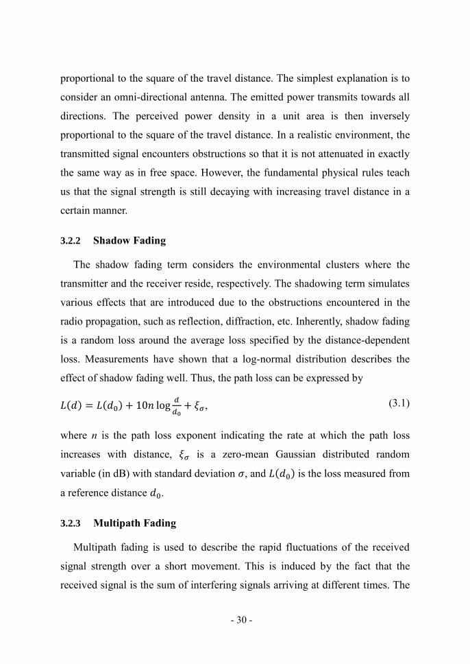
effect of shadow fading well. Thus, the path loss can be expressed by
(𝑑) = (𝑑 ) + 10𝑛 log
+ , ( 3.1)
where n is the path loss exponent indicating the rate at which the path loss
increases with distance, is a zero-mean Gaussian distributed random
variable (in dB) with standard deviation , and (𝑑 ) is the loss measured from
a reference distance 𝑑 .
3.2.3 Multipath Fading
Multipath fading is used to describe the rapid fluctuations of the received
signal strength over a short movement. This is induced by the fact that the
received signal is the sum of interfering signals arriving at different times. The
Page 46
- 31 -
difference in the arrival time of the interfering signals is because they arrive at
the receiver via different transmission paths. In systems with carrier frequency
in the order of Giga Hz, a movement of the receiver in the order of one meter is
more than enough to bring the channel from a constructive interference to a
destructive interference situation.
3.3 Channel Model
A comprehensive evaluation of communication systems requires channel
models that allow realistic modelling of the propagation conditions in different
environments. For this, channel modelling for different environments has been
one of the earliest research fields in wireless communications. On the other
hand, leaving the capability of capturing the propagational insights aside, we
do need reference models based on which different techniques are able to be
compared. A number of reference channel models have been developed for this
purpose. Examples include COST [34], WINNER [5], and ITU [35]. A
comparison between COST 273 and WINNER is available in [36]. In this
work, we consider a WINNER B3 – Indoor hotspot scenario.
The WINNER B3 channel model represents the propagation conditions
pertinent to operation in a typical indoor hotspot, with wide, but non-ubiquitous
coverage and low mobility (0-5 km/h). Traffic of high density would be
expected in such scenarios, as for example, in conference halls, factories, train
stations and airports, where the indoor environment is characterised by larger
open spaces, where ranges between a BS and a MS or between two MS can be
significant. Typical dimensions of such areas could range from 20 m × 20 m up
to more than 100m in length and width and up to 20 m in height. Both LOS and
NLOS propagation conditions could exist.
Distance-dependent path loss is calculated from the parameters A, B, C as
Page 47
- 32 -
= 𝐴𝑙𝑜𝑔 (𝑑,𝑚-) + 𝐵 + 𝐶 log . , -
/ + 𝑋 ( 3.2)
where 𝑑 is the distance between the transmitter and the receiver in ,𝑚-, 𝑓 is
the system frequency in , -, the fitting parameter A includes the path-loss
exponent, parameter B is the intercept, parameter C describes the path loss
frequency dependence, and X is an optional, environment-specific term (e.g.,
wall attenuation in the A1 NLOS scenario). The most important characteristics
of the path loss model are given in Table 3. 1.
Table 3. 1 Parameters of the WINNER II B3 Path Loss Model
BS height ( ) 6 𝑚
MS height ( ) 1.5 𝑚
Distance 𝑑 ,𝑚- 5 𝑚 < 𝑑 < 100 𝑚
LOS path loss 𝐴 = 13.9 𝐵 = 64.4 𝐶 = 20 NLOS path loss 𝐴 = 37.8 𝐵 = 36.5 𝐶 = 23 LOS shadow fading std. ,𝑑𝐵- 3 𝑑𝐵
NLOS shadow fading std. ,𝑑𝐵- 4 𝑑𝐵
3.4 WINNER Channel Model Overview
The European WINNER (wireless world initiative new radio) project began
in 2004 with the aim to develop a new radio concept for beyond third
generation (B3G) wireless systems. Work Package 5 (WP5) of the WINNER
projects focused on multi-dimensional channel modelling for carrier
frequencies between 2 and 6 GHz and bandwidths up to 100 MHz. In total six
organisations were formally involved in WP5 (Elektrobit, Helsinki University
of Technology, Nokia, Royal Institute of Technology (KTH), the Swiss Federal
Institute of Technology (ETH) and the Technical University of IImenau).
In September 2007, the WINNER channel model - Phase II (WIM2) was
described. This model is evolved from WIM1 and the WINNER II interim
channel models. The WINNER channel model – Phase 1 (WIM1) was
described at the end of 2005. WIM1 has a unified structure for indoor and
Page 48
- 33 -
outdoor environments and is based on double-directional measurement
campaigns carried out in the 5 GHz ISM2 band with bandwidths of up to 120
MHz. It covers six different propagation scenarios, i.e.(i) indoor small office,
(ii) indoor hall, (iii) urban microcell, (iv) urban macrocell, (v) suburban
macrocell, and (vi) rural . Both line-of-sight (LOS) and non-line-ofsight
(NLOS) propagation conditions are catered for. The WIM2 extended the
propagation scenarios to: (i) indoor office, (ii) large indoor hall, (iii) indoor-to-
outdoor, (iv) urban microcell, (v) bad urban microcell, (vi) outdoor-to-indoor,
(vii) stationary feeder, (viii) suburban macrocell, (ix) urban macrocell, (x) rural
macrocell, and (xi) rural moving networks. In the course of the WINNER
project channel models were implemented in MATLAB and made available
through the official web site.
The WIM2 channel model is defined for both link-level and system-level
simulations. WINNER MIMO radio channel model enables system level
simulations and testing. This means that multiple links are to be simulated
simultaneously. System level simulation may include multiple base stations,
multiple relay stations, and multiple mobile terminals. The channel model takes
the user defined parameters, the MIMO radio link parameters and antenna
parameters as an input. Channel matrices can be generated for multiple BS-MS
links with one function call. The output is a multi-dimensional array which
contains the channel impulse responses for the given radio links. In addition,
the randomly drawn channel parameters for each link will be given as an
output.
Page 49
- 34 -
Figure 3. 2 System Level Approach [5].
3.4.1 Coordinate Systems in WIM2
The WIM2 Channel Model uses two main coordinate systems in order to
fully describe positions and directivity of antenna elements in 3D space, the 2
coordinate systems used are:
a) GCS – Global Coordinate System:
used to define radio-network system layout, and as a reference system
for polarization).
b) ACS – Array Coordinate System:
describes array geometry and rotated radiation patterns of antenna
elements.
Furthermore, the channel model uses a third Element-Coordinate-System
(ECS) to represent radiation pattern of each antenna element which is not
suitable since it increases simulation complexity. Therefore, it is concluded that
the most suitable representation for element field patterns is Effective-
Aperture-Density-Functions (EADF) (See [37] for details) defined for all
elements in the array in respect to common ACS.
Page 50
- 35 -
Figure 3. 3 Relations between Coordinate Systems [5].
3.4.2 Antenna Arrays Definition and Construction
A certain type of antenna array requires only single construction, which is
performed independently from WIM simulations - in a pre-processing phase. It
is not a good strategy to construct arrays each time when WIM is used, instead
defined antenna arrays are stored and retrieved when needed [5].
In order to define an antenna array it is necessary to define its geometry
(positions and rotation of elements), and to provide the element field patterns.
Following are some examples of the supported options for Array Structures,
where in Example1, the antenna array position and rotation of each array
element are defined with respect to the ACS and field pattern samples are
defined in the ECS. On the other hand, Example2 and Example3 define array
elements positions and rotations according to the common array types ‗UCA‘
Page 51
- 36 -
and ‗ULA‘, respectively, defined in the next section. Moreover, field patterns
are defined in the ECS and ACS, respectively.
Example1=AntennaArray('Pos',Position,’Rot’,Rotation, ’FP-ECS’, FieldPattern);
Example2=AntennaArray('UCA',N,r, ’FP-ECS’, FieldPattern);
Example3=AntennaArray('ULA',N,d, ’FP-ACS’, FieldPattern);
3.4.2.1 Antenna Arrays Definition – Array Geometry (AG)
We notice that Geometry is defined using ‗Pos‘ and ‗Rot‘ arguments
followed by ELNUMx3 matrix, where ELNUM is the number of elements. We
also notice that Array Geometry can be defined using common array types
Uniform-Circular-Array ‗UCA‘ and Uniform-Linear-Array ‗ULA‘ with few
parameters only.
For UCA, elements are placed starting from x-axis (phi=0) every 2
π
φN
∆φ =
, and n
th element is rotated for ( 1) n φ (n-1)∆φin counter-clockwise
direction. On the other hand, ULA elements are placed along x-axis in such a
way that the center of the array is at [0; 0; 0]. In ULA, when N is even, there is
no antenna element at [0; 0; 0], where N represent the number of Antenna
Elements.
As default geometry, if there are no parameters defining geometry, single
antenna positioned at centre of ACS, without rotation is considered. Table 3. 2,
explains the parameters of Array Geometry.
Page 52
- 37 -
Table 3. 2 Array Geometry Parameters [5]
3.4.2.2 Antenna Arrays Definition – Field Pattern (FP)
The field patterns of individual array elements are described using the
EADF defined in ACS. This was done because EADF has proven to be superior
in terms of memory requirements and interpolation errors. The two different
argument types, ‗FP-ACS‘ and ‗FP-ECS‘, are used to distinguish between FPs
that are expressed in ECS and ACS.
As default field pattern, if neither ‗FP-ACS‘ nor ‗FP-ECS‘ are defined,
isotropic, vertically polarized antenna with XPD=∞ is used. Table 3. 3, explains
the parameters of Field Pattern.
Page 53
- 38 -
Table 3. 3 Array Geometry Parameters [5]
3.4.2.3 Arrays Construction Examples
The function arrayparset is used to generate six different array
structures. The function dipole(Az, Slant) is used to generate the field
pattern samples at different azimuth values defined by Az for a dipole antenna
slanted by the value Slant. For example, Arrays(1) represent a ULA array
with two antenna elements spaced 1 cm from each other.
function Arrays=arrayparset
NAz=120; %3 degree sampling interval Az=linspace(-180,180-1/NAz,NAz); %pattern=zeros(1,2,1,length(Az));%[NumElem Pols(2) NumEle NumAz] pattern(1,:,1,:)=dipole(Az,12); % slanted by 12 degree Arrays(1)=AntennaArray('ULA',1,0.01,'FP-ECS',pattern,'Azimuth',Az); %ULA-1 1cm
spacing Arrays(2)=AntennaArray('ULA',4,0.01,'FP-ECS',pattern,'Azimuth',Az); %ULA-4 1cm
spacing Arrays(3)=AntennaArray('ULA',8,0.01,'FP-ECS',pattern,'Azimuth',Az); Arrays(4)=AntennaArray('UCA',4,0.01,'FP-ECS',pattern,'Azimuth',Az); %UCA-4 1cm
radius Arrays(5)=AntennaArray('UCA',8,0.01,'FP-ECS',pattern,'Azimuth',Az);
NAz=360; %1 degree sampling interval Az=linspace(-180,180-1/NAz,NAz); pattern=ones(2,2,1,NAz); dist = 3e8/5.25e9*0.5; Arrays(6)=AntennaArray('ULA',2,dist,'FP-ECS',pattern); % isotropic antenna
Page 54
- 39 -
3.4.3 System Level Layout Design
3.4.3.1 Construction of Semi-Random Layout
The function layoutparset.m is used to generate random positions for
all stations, and assigns random scenario and propagation conditions to all
links. MSs and BSs locations are randomly generated within e.g. the
500x500m2 cell area where a default height of 32 m is used for BSs and 1.5 m
for MSs. The following command is used to call the function
layoutparset.m.
layoutpar=layoutparset(MsAAIdx, BsAAIdxCell, K, Arrays)
where;
– Arrays: Vector of Antenna Array definitions, as can be generated by the
methods described in the previous section.
– MsAAIdx: Vector of UE’s/MS’s Antenna Arrays indices.
– BsAAIdxCell: Vector of Cell/BS Antenna Arrays indices.
– K: Number of links which are formed by random BS-MS pairing.
There are some assumptions that are made by the WIM2 channel model for the
multi-sector base station, these assumptions are:
– Different sectors of multi-sector-BS are closely located and therefore links
between a MS and different sectors in the same BS exhibit high correlation.
– Links from a MS to different sectors are still not identical due to the
specific array orientation, and directional filtering, and because they use
different low-level parameters.
– Sectors of the other BSs are assumed to be located ―very far away‖, so that
there is no considerable correlation between links from a specfic MS toward
sectors belonging to different BSs.
Page 55
- 40 -
3.4.3.1.1 Example Layout Parameters
>> MsAAIdx = [1 1 2 3];
>> BsAAIdxCell = {[1 3]; [2]; [1 1 2]};
In this scenario 4 MS are considered where the first two will use array type
defined in Arrays(1) the third MS will use Arrays(2) and the fourth Arrays(3).
Moreover, three multi-sector-BSs are present in the scenario where:
– The first has two sectors, that are using Arrays(1) and Arrays(3).
– The second is one-sector-BS with Arrays(2).
– The third has three sectors: two of them are using Arrays(1) and one is using
Arrays(2).
3.4.3.2 Layout Manual Editing
To edit the scenario layout manually, we start from the previous semi-
random layout and then:
– (BS, MS) pairs could be defined by modifying layoutpar.Pairing.
– Position and orientation of each station could be manually adjusted using
layoutpar.Station.Pos/Rot parameters.
– Change of per-link scenario and propagation conditions can be modified
through
layoutpar.ScenarioVector/PropagConditionVector
These parameters are given in more detail in Table 3. 4 and Table 3. 5.
Page 56
- 41 -
Table 3. 4 Network Layout Parameters [5]
Page 57
- 42 -
Table 3. 5 Stations (Array) Parameters [5]
3.4.3.2.1 Manual Edited Example
In this example, we present a single three sector base station along with two
mobile stations.
>> MsAAIdx = [1 1];
>> BsAAIdxCell = {[1 1 2]};
>> layoutpar=layoutparset(MsAAIdx, BsAAIdxCell, NumOfLinks, Arrays);
>> layoutpar.ScenarioVector=10*ones(1, NumOfLinks); % C1 scenario
% first we define the position and rotation of the three sector base station.
% defining sector #1 parameters
>> layoutpar.Stations(1,1).Pos=[20; 30; 30];
>> layoutpar.Stations(1,1).Rot=[0; 0; 0];
>> layoutpar.Stations(1,1).Velocity=[0; 0; 0];
% defining sector #2 parameters
>> layoutpar.Stations(1,2).Pos=[20; 30; 30];
>> layoutpar.Stations(1,2).Rot=[0; 0; 2*pi/3]; % 120 degree rotation in z-
direction
>> layoutpar.Stations(1,2).Velocity=[0; 0; 0];
% defining sector #3 parameters
>> layoutpar.Stations(1,3).Pos=[20; 30; 30];
>> layoutpar.Stations(1,3).Rot=[0; 0; 4*pi/3]; % 240 degree rotation in z-
direction
>> layoutpar.Stations(1,3).Velocity=[0; 0; 0];
% defining MS#1 parameters
>> layoutpar.Stations(1,4).Pos=[60; 90; 1.5];
>> layoutpar.Stations(1,4).Rot=[0; 0; 0];
Page 58
- 43 -
>> layoutpar.Stations(1,4).Velocity=[0.7; 0.1; 0];
% defining MS #2 parameters
>> layoutpar.Stations(1,5).Pos=[-60; 90; 1.5];
>> layoutpar.Stations(1,5).Rot=[0; 0; 0];
>> layoutpar.Stations(1,5).Velocity=[-0.7; 0.1; 0];
% pairing sector #1 to MS #1, and sector #2 to MS #2
>> layoutpar.Pairing=[1 2;4 5];
% Generating Layout visual graph
>> NTlayout(layoutpar);
Figure 3. 4 Manual Edited Example Layout Virtualization.
3.4.4 WIM2 Model Input and Output Parameters
The Matlab command that is used to call the WIM2 channel model is:
[H, [DELAYS], [FULL_OUTPUT]] = WIM (WIMPAR, LAYOUTPAR, [INITVALUES])
Where the global simulation parameters are defined in the input parameter
WIMPAR, such as:
– CenterFrequency [Hz]
– NumTimeSamples
– SampleDensity
– DelaySamplingInterval [sec]
Page 59
- 44 -
– PathLossModelUsed
– ShadowingModelUsed
The SampleDensity should be set as follows
>>wimpar.SampleDensity=
speed_of_light/(2*CarrierFreq*Channel_Sampling_Time*newMsVelocity
This is to have a time sample interval as follows
The time sample interval = wavelength/(MsVelocity*SampleDensity)
We notice that for block fading, channel_sampling_Time should be
equal to 1 TTI (one sub-frame). On the other hand, for fast fading,
channel_sampling_time should be equal to Ts, where
𝑇 =1
𝐹 ( 3.3)
3.4.4.1 Initialization of the Structural Model Parameters
This option is provided to enable consecutive calls of wim.m functions,
without (default) random initialization of structural parameters. This means that
structural parameters obtained after one simulation run could be used to
initialize new run, preserving in that way previous channel conditions – what
somehow means continuation of the previous simulation run. This enables
performing seamless channel simulation in several simulation runs.
[INITVALUES]new_run=[FULL_OUTPUT]old_run ( 3.4)
3.4.4.2 WIM2 Model Output
The cell array H of size K, number of links, is a multi-dimensional array
which contains the channel impulse responses for the given radio links. Each
element of this cell array contains a U x S x N x T matrix, where
– U number of receiver elements
– S number of transmitter elements
– N number of paths/clusters/taps
– T number of time samples
Page 60
- 45 -
In addition, the randomly drawn channel parameters for each link will be given
as an output, FULL_OUTPUT, which is a Matlab structure with the elements
given in Table 3. 6.
Table 3. 6 FULL_OUTPUT Elements [5]
3.4.4.3 OFDM Channel Outputs
In this section we will describe the steps used to convert the obtained
channel impulse responses for the given radio links into the frequency domain.
In this section we will only consider the case where each node is equipped with
one element antennas. Thus, the dimensions of the K elements of the Winner
channel model cell array output H is confined to a 1 x 1 x N x T matrix, simply
referred to, from now on, as an N x T matrix. The WIM2 model provides the
output matrix DELAYS of size K x N which represents the time delay for each
of the K links for N paths.
Page 61
- 46 -
First, we round the values of DELAYS to be represented as integers of the
sampling time TS.
Delays_rounded = round(DELAYS*Fs);
The number of taps corresponding to the system sampling time is then
calculated as
Tap_Number = max(Delays_rounded)+1;
For each tap, we find all the paths that have time delay that is close or equal to
the tap time delay and then add their corresponding gain and phase shift
response
Tap_positions = find(Delays_rounded(K,:) == 1 );
h( , t) = sum(H{K}( Tap_positions, t));
where represents the tap time delay index and t represents the time sample.
The matrix h( , t) is then converted to the frequency domain using the Fast
Fourier Transform (FFT) with a size suitable for the system sampling
frequency.
3.4.4.4 Sample Output
In this section we provide an example output for the mean gain per resource
block (RB) for the two links provided in the earlier example in
section 3.4.3.2.1. Table 3. 7 summarizes the parameters used.
Table 3. 7 Simulation Parameters
Parameter Value
Carrier Frequency (GHz) 2
Sampling Frequency (MHz) 30.72
FFT Size 2048
Number of RBs 100
In Figure 3. 5, average channel gain per RB is shown for the first link for 100
RBs. The average channel gain for the second link is shown in Figure 3. 6.
Page 62
- 47 -
Figure 3. 5 Average Channel Gain per RB for Link #1.
Figure 3. 6 Average Channel Gain per RB for Link #2.
Page 63
- 48 -
4 Device-to-Device Communication underlay in
Cellular Networks
The demand on enhanced data transmission for diverse mobile multimedia
rich services has been addressed in next generation communication systems
under, for example, the scope of IMT-Advanced systems. One aspect that
deserves more attention in considering IMT-Advanced systems is the emerging
needs for high data rate local services. In [26], [27], a proposal has been made
to handle local P2P traffic by enabling direct D2D communication as an
underlay to the IMT-Advanced cellular systems. The introduction of D2D
communication achieves higher spectral efficiency as D2D connections reuse
the same resources as the underlying cellular network. The mutual interference
between D2D and normal cellular connections can be coordinated since users
engaged in D2D communication are still under the control of their serving BSs
(e.g., eNodeBs in LTE-Advanced systems). D2D communication is a promising
technology component which allows a tight integration into an LTE-Advanced
network [27].
4.1 Introduction
D2D communication as an underlay to a cellular network is illustrated
in Figure 4. 1. Direct communication between UE1 and UE2 via D2D radio is
controlled by the eNodeB. The cellular services are provided to other UE as
usual with the D2D operation transparent to them. In principle, D2D
communication is different from cooperative relaying in that the D2D
connections are to handle possibly bidirectional local P2P traffic in a more
spectrally efficient manner than it would be when using the BSs as relay i.e.,
normal cellular operation.
Page 64
- 49 -
D2D communication can operate in different modes for resource sharing
both in cellular DL/UL transmission. The cellular network can assign dedicated
resources to the D2D links so that the mutual interference between the two
types of systems is negligible. Alternatively, the D2D connections can reuse the
same resources used by the cellular links nonorthogonally. Similar to the
principles of cognitive radio systems, it is crucial that D2D communication
does not generate harmful interference to the primary system (i.e., normally
operating cellular system). This is easier with D2D communication as it is
controlled in cooperation with the cellular network. D2D communication
enables cellular operators to offer cost-efficient access to the licensed spectrum
[26] as those promised by Wireless Local Area Networks (WLAN). WLANs
have become increasingly popular in recent years as they provide economic
and convenient access to the Internet and local services in the license exempt
bands. Similar services enabled by D2D communication exhibit additional
advantage of providing a planned environment for more reliable transmissions.
Different standards addressing the needs for D2D operation in the same
bands as infrastructure-based operation can be found, such as Wi-Fi1. For Wi-Fi
technology that is based on IEEE 802.11 standards, UE can sense and access
the radio medium only if the channel is free. Accordingly the access points do
not have full control over the resources used by the ad hoc D2D links. Wi-Fi
technology supports a Wi-Fi direct mode that allows direct D2D connection
between peers. However, Wi-Fi direct mode requires users to manually pair the
peers, as is the case for Bluetooth technology. In the D2D underlay
communication, the pairing can be handled by BSs and thus provides new use
cases and better user experiences [26].
1 see http://www.wi-fi.org/
Page 65
- 50 -
Figure 4. 1 D2D communication works as an underlay to a cellular
network.
4.2 Coexistence of Cellular and Ad Hoc Networks
The embedded ad hoc network introduced in earlier work is for relaying
purpose. In principle, ad hoc networks can be embedded for handling local P2P
traffic in cellular networks since this is how the ad hoc networks were designed
for in the very beginning. Nevertheless, some problems remain for applying the
ad hoc networks in a two-tier network. Firstly, the spectral utilization of the
Page 66
- 51 -
licensed bands is not improved since two different frequency bands are
assumed for two different air interfaces. In addition, the ad hoc D2D
connection supported by WLAN protocols may be inefficient as interference
coordination is usually not possible. Although opportunistic use of ad hoc D2D
connections by WLANs provides performance improvement, WLANs cannot
be counted on as reliable means for this purpose [26].
The D2D operation discussed in [26] and [25] assumes that the cellular
and D2D connections are under the control of cellular networks. The traffic
originated from users can be either provided through the cellular or the D2D
connections. Thus, D2D and cellular traffic can be treated as coming from the
same pool. The interference situation can be planned for effective interference
management. In addition, the possibility of selecting different resource sharing
schemes in [25] facilitates more efficient spectral usage. This allows not only
better spectral utilization of licensed bands, but also provides the possibility of
more effective protection of the cellular network.
4.3 New Local Services with D2D Communication
D2D communication is envisioned in [38] as an enabler of new types of
local services such as the case where a media server is installed at a rock
concert tour from which visitors can download promotional material using the
D2D radio. The organizers of the rock concert simply put up the media server
which registers to the cellular network and it is immediately operational.
Alternatively, the cellular network could handle the traffic from the media
server. However, this would cause a heavy load to the cellular network. When
using the D2D radio, the cellular network can handle phone calls and internet
data traffic without the additional load from the promotional material.
Moreover it can control the interference from the D2D communication to the
cellular network to limit its impact to the cellular communication.
Page 67
- 52 -
As a second alternative, WLAN or Bluetooth could be used. However,
since they operate in the license exempt band, the organizers cannot be sure if
the media server will work at every place they visit. There is always the
possibility of the presence of interfering communication systems or other
sources of interference.
The D2D operation itself can be transparent to the user. Once the user
enters a URL, the network detects traffic to the media server and hands it over
to a D2D connection. Since both D2D devices have already a secure
connection to the cellular network, it is easy to setup a secure D2D connection.
Thus, compared to WLAN or Bluetooth no manual pairing or access point
definition is required.
The D2D communication also allows sharing of for example photos or
videos taken by a mobile device between users. The videos can be shared
without pairing Bluetooth devices or setting up an ad-hoc connection. Again
the cellular network will hide the complexity of setting up the D2D connection
from the user.
4.4 Cooperative Transmission Through Network Coding
The D2D communication between terminals is an enabler of cooperative
transmission and relay-based communications through network coding which is
studied in [27]. A novel network protocol applied to uplink cellular traffic
protocol with an efficient decoding approach at the receiver is proposed.
Network Coding is currently emerging in multi-hop multi-user wireless
networks. Comparing to traditional routing techniques, network coding allows
information processing in the intermediate nodes. Performance gains in energy-
efficiency, fairness, robustness, or coverage are obtained. It is shown in [38]
that carefully designed non-binary network codes can substantially decrease
Page 68
- 53 -
outage probability/frame error rate (FER), for multiple-user cooperative
communications. Moreover, a study of user grouping is conducted to determine
which set of users shall be selected and grouped to perform the network coding
operation as it was obvious that random selection will not yield the optimal
capacity of the system.
4.4.1 Network Coding
Figure 4. 2 illustrates the usage of network codes on top of the channel
codes. The relaying and local messages are encoded by network codes in the
relay node. The network coding scheme is fixed in each relay node
(deterministic codes). The network codes are designed such that any two
successfully received blocks out of four transmission blocks can rebuild two
source message blocks.
In the first time slot, the two source nodes use proper channel coding to
transmit their own messages I1 and I2 respectively (in e.g., different frequency-
orthogonal channels). In the second time slot, if both relay nodes successfully
decode the channel codes, the transmitted messages for UE1 and UE2 are
encoded using network coding as + and + 2 , respectively. Here ―+‖
operation is in, finite field or Galois field, GF(4). Then, the resulting blocks are
channel encoded and transmitted. If a relay node cannot decode correctly, it
instead repeats its own message using the same channel code. Upon receiving
repeated codewords, the BS performs MRC (maximum ratio combination) of
these codewords and decodes.
The receiver can rebuild the source blocks I1 and I2 upon receiving any
two of the four transmitted blocks and a network error event occurs only when
three or more blocks cannot be decoded correctly from channels. Thus, a higher
diversity gain is achieved and better performance is expected.
Page 69
- 54 -
Figure 4. 2 Proposed two-user cooperative networks in [38].
4.4.2 User Grouping
A random selection of users groups will not yield the optimal system
capacity. More specifically, if we choose to pair users randomly then we could
end up pairing users with non-complementary channel conditions to the base
station, and consequently losing the advantage provided by network coding.
The proposed network coding scheme allows only one of the network coded
pair to increase its SINR through the relay connection whereas the other user
has to be decoded through its direct connection's SINR. Therefore, if both of
the grouped users have a bad channel towards the base station, one of them will
be decoded with a low SINR. Similarly, if both users have a good channel
towards the base station, the capacity would decrease as compared to a direct
transmission due to the time division among the users and the base station.
Page 70
- 55 -
Consequently, grouping users with complementary characteristics is essential
in order to ensure a good performance of the network coding scheme. More
details about user grouping can be found in [38].
4.5 Interference Coordination in a D2D Enabled Cellular Network
Proposals for D2D communication underlaying cellular networks that
share the radio resources non-orthogonally can be found in [25], [26], [39],
[40], [41]. A single air interface for D2D and cellular operation is assumed.
Furthermore, in these proposals, D2D users are under the control of the cellular
network to facilitate the coordination of mutual interference. Tight cooperation
of D2D and cellular operation is envisioned, depending on the extent of local
awareness of the BSs to the interference situation between cellular and D2D
users sharing the same resources.
The four different possibilities considered on how to share the available
resources are:
DL resource sharing: D2D communication happens in DL resources so
that all the DL resources of the cellular user are interfered.
UL resource sharing: Similar to DL resource sharing, D2D
communication happens in UL resources, and all the UL resources of the
cellular user are interfered.
Separate resource sharing: The D2D communication takes half of the
available resources from the cellular user, either from DL or UL
resource. There is no interference between cellular and D2D
communication.
Cellular mode sharing: The D2D users communicate with each other
through the BS that acts like a relay node. They take half of the available
resources either from the DL or the UL resources of the cellular user.
Page 71
- 56 -
Noting that this mode is conceptually the same as a traditional cellular
system.
To incorporate D2D operation into a cellular network without harmful
impact on cellular operation, resources of cellular UL phases provide features
that admit less overload than cellular DL phases. Figure 4. 3 demonstrates the
direct and interfering links in both UL and DL phases. In the cellular UL
phases, the transmit power of cellular users is power-controlled to maintain a
target, for example, received SNR at the BSs. The impact of D2D transmitters
on the BS can thus be learnt without any extra mechanism compared to state-
of-the-art cellular architectures. In principle, no such power control scheme is
assumed in the cellular DL phases. Assuming the awareness of the SINR target
and the power control results i.e., the maximum allowed transmit power, at
D2D users, D2D transmitters can decide the D2D transmit power to emit a
tolerable interference to cellular UL transmissions.
The performance of D2D connections can be improved with slightly
more D2D-oriented considerations. For D2D operation in the cellular DL
phases, conservative D2D transmit power can be planned to limit the
degradation of cellular DL users. However, this results in limited space for
D2D operation in the cellular DL resources. For enhancement, an interference-
avoiding MIMO scheme is proposed in [39]. As the interference to the D2D
receivers is generated by the BSs in the cellular DL phases, it is possible to
mitigate the interference by precoded DL transmission if the BSs are equipped
with multiple antennas. By knowing the interference channel between a BS and
a D2D receiver, the BS can align its transmission to the null space of the
interference channel. Furthermore, the BS is still free to apply any MIMO
transmission scheme for its DL transmission on the projected subspace. The
results show significant SINR gain for D2D operating in cellular DL phases in
the cost of minor cellular SINR degradation.
Page 72
- 57 -
4.5.1 D2D Communication with Full CSI
With full CSI, the resource sharing between the cellular and D2D
connections can be optimized [1], [25]. Considering a case where one cellular
user (UE1) and two D2D users (UE2 and UE3) share the radio resources, as
illustrated in Figure 4. 4, where gi is the channel response between the BS and
UEi and gij is the channel response between UEi and UEj. The sum rate for
sharing the resources non-orthogonally (Non-Orthogonal Sharing, NOS) can be
found by summing up rates from the cellular link and the D2D link
( ) = log (1 + ( )) + log (1 + ( )) ,
( 4.1)
Where
( ) =
( ) n ( ) =
.
We have denoted by gcd the channel response of the interference link from the
cellular connection to the D2D connection, and vice versa for gdc. We used Ic
and Id to indicate the interference-plus-noise power at the receiver of the
cellular link and the D2D link, respectively.
With a greedy sum rate maximization strategy, the optimal power
allocation of (5.1) is a feasible solution of the optimization problem
( ) = gm ( )∈ ( ),
= * 0 +,
( 4.2)
where defines the feasible set of ( ). It is shown that the optimal power
allocation to (4.2) is searched over the following 3 possible sets =
*( ) (0 ) ( 0) ( )+ [42].
Page 73
- 58 -
To prioritize the cellular connection, we can set a SINR constraint to
lower-bounded . In practice, the higher transmission rate is also constrained
by the limited amount of modulation and coding scheme (MCS). Hence, one
can impose an upper limit on the SINR. The sum rate optimization subject to
the mentioned constraints is
( ) = gm ( )∈ ( ) ,
= * 0 ( )
( ) +,
( 4.3)
where defines the feasible set of ( ), is the SINR needed for using
the highest MCS, and is the guaranteed SINR to prioritize the cellular
connection.
In [25] and [1], the optimization is also performed for both transmit
power and radio resources for an orthogonal resource sharing mode. The
optimization of a reference mode where the BS is used as a relay for D2D
operation (conceptually the same as traditional cellular connection) is
addressed. As shown in [25] and [1], non-orthogonal resource sharing between
D2D and cellular communication does not always yield better performance
than orthogonal resource sharing where dedicated resources are assigned
separately for both types of communication. Therefore, it is sensible to admit
mode selection on resource sharing between D2D and cellular communication
for better spectrum utilization, in a single cell scenario as illustrated in Figure
4. 4, if the BS is empowered for coordination.
The optimization of resource sharing between paired connections does
not impede the application of inter-cell interference control mechanisms for
efficiently managing inter-cell interference based on the power control or
resource scheduling. In fact, the resource sharing schemes in [1], [25] which
aim at improving intra-cell spatial reuse of spectrum enabled by D2D underlay
Page 74
- 59 -
communication shall work on top of the inter-cell interference control schemes
from the perspective of overall system performance. The proposed mechanism
in [26] for integrating D2D functionality in LTE-Advanced systems indicates
that proper coordination from BSs, including mode selection, is feasible.
Figure 4. 3 Illustration of direct and interfering links in a D2D enabled
cellular network.
Page 75
- 60 -
Figure 4. 4 D2D communication as an underlay to a cellular network
4.5.2 D2D Communication with Limited CSI
With practical considerations, the CSI between a transmission pair is
acquired at the receiver by the insertion of training symbols at the transmitter.
In time-varying channels, reliable CSI requires frequent enough insertion of
training symbols. In addition, for Frequency Division Duplex (FDD) systems
where the channel reciprocity property does not exist, the acquisition of DL
CSI at the BSs requires users to feed the measurement of channel responses
back. The feedback rate required for achieving reliable CSI at BSs depends on
the channel fading rate, which is related to user mobility. In principle, reliable
CSI at BSs is not problematic in state of-the-art cellular systems such as 3GPP
LTE [43]. However, for interference coordination in D2D underlay systems,
additional loads on users for inter-user channel measurement are required.
Tracing instantaneous CSI on inter-user links may indicate a high feedback rate
Page 76
- 61 -
(dependent on user mobility) which may not be favored for practical
implementation. To reduce the amount of such channel reports, it is likely that
users only report an average version of CSI. As instantaneous interference
coordination such as the analysis in [25] requires reliable CSI, using only
average CSI usually indicates performance degradation.
One interesting aspect of the D2D underlay system would be the
achieved performance with very limited CSI for coordination. In [44], a single
cell scenario with one cellular user and one D2D pair is studied, assuming only
channel statistics on all the related links for coordination. The cellular user
(UE1) is assumed to reside in the cell area with uniform probability. One of the
D2D users (UE2) is assumed to stay at a fixed distance D from the BS, and the
other D2D user (UE3) is assumed to reside at most L distance from UE2 with
uniform probability, as illustrated in Figure 4. 5. The upper limit on the D2D
transmission range can be justified by the fact that D2D communication is
generically for short range communication. To prioritize the cellular services,
the D2D transmit power is reduced to maintain a 3-dB SINR degradation of the
cellular user at 0.05 outage probability. The results show that a dynamic power
control based on the position of the D2D pair i.e., distance D, is more needed in
the cellular UL phases. This is because in the cellular UL phases, the
interference generated from the D2D transmission is only related to the
distance D, but not the position of the cellular users. With such a power control
scheme which admits only a small amount of D2D transmit power compared to
the cellular transmit power, we observe that the realized D2D SINR is
comparable or higher than the cellular SINR in most of the cell area.
Page 77
- 62 -
Figure 4. 5 System settings in [44].
Page 78
- 63 -
5 Radio Resource and Interference Management in
D2D Underlay via Clustering and Interference
Alignment
Enabling underlay direct Device-to-Device (D2D) communication mode in
future cellular networks has good potential for spectrally-efficient and low-
latency support of local media services. Recently, it has become evident that
shrinking the reuse distance over which wireless resources are reused is a key
enabler for achieving high spectral efficiency. Moreover, as discussed in
chapter 2 , IA based transmission can enhance the capacity of a wireless
network by providing more degrees of freedom. In this work, we propose a
framework for radio resource management in D2D underlay network based on
reusing radio resources over smaller distances as defined by constructing
groups of the D2D pairs and using IA to manage interference. Firstly, we
explore using IA techniques in a D2D as an effective means to manage
interference in order to enhance spectral efficiency. We compare IA
transmission and traditional point-to-point (P2P) transmission from the Bit-
Error-Rate (BER) and sum-rate points of view. We also propose three grouping
schemes for the D2D users into groups of 3-pairs such that IA can be applied
using a limited number of signal extensions. Secondly, we propose clustering
of D2D users, reuse radio channels over the clusters and then using IA within
each group in the cluster enhance the sum rate. Specifically, we show that in a
D2D environment, it is possible to achieve significant gains in attainable rates
by constructing clusters of D2D pairs and reuse the available radio resources
over the clusters. Additionally, within a cluster, it is possible to further enhance
the spectral efficiency by constructing small-sized groups of D2D pairs over
which IA is applied to offer additional degrees of freedom. Results demonstrate
Page 79
- 64 -
that although traditional P2P transmission can achieve better BER
performance; IA transmission is still able to achieve gains in the sum rate. We
also show that resource reuse over the clusters offer overall rate increase
proportional to the number of formed clusters. In addition, interference
alignment offers up to 33% increase in the overall rates in the high transmission
power regimes compared to the normal Point-to-Point (P2P) communication.
5.1 Introduction
Wireless communication systems are in continuous evolution as a result of
the ever increasing demand for higher data rate services. Recently, direct
device-to-device communication (D2D) as an underlay network to IMT-
Advanced cellular networks [1] has been proposed which represents a
promising technique that is expected to provide efficient utilization of the
available wireless spectrum. This technique has been proposed as a new
technology component for LTE-Advanced that is expected to provide access to
the Internet and local services using licensed bands that can guarantee a
planned environment. There are many advantages for enabling D2D
communication: offloading the cellular system, reducing battery consumption,
increasing bit-rate, increasing robustness to infrastructure failures as well as
enabling new services.
On another front, recently, a new paradigm shift in the design of wireless
systems has occurred where it has become evident that enhancing the proximity
between the access network and the end users has the potential to provide the
next performance leap in attainable rates via spatial spectrum reuse and to
enhance indoor coverage as well [18]. LTE-Advanced provides means for
deployment and planning of pico- and femto-cells, which are characterized by
small transmission power and coverage radius thus enabling reuse of spectrum
resources over a smaller area.
Page 80
- 65 -
Additionally, IA which has the potential to boost the overall cellular spectral
efficiency, as discussed in chapter 2, allows signal vectors to be aligned in such
a manner that they cast overlapping shadows at the receivers where they
constitute interference while they continue to be distinct at the intended
receivers [2]. Using IA, the interference channel is shown not to be essentially
interference limited. In contrast, IA offers the wireless interference channel
with K transmitter–receiver pairs the ability to simultaneously provide each
user the opportunity to send at a data rate equal to half of his interference-free
channel capacity to his desired receiver, even though the number of users K can
be arbitrarily large. Usually, calculation of precoding vectors required to apply
IA becomes more complex as the number of users K and correspondingly the
number of symbol (channel) extensions increases. Thus, a good mass of
previous research work focused on the 3-user interference channel.
Motivated by the above, in this work, we focus on how to benefit from the
extra degrees of freedom that IA offers to further boost the capacity of
macrocells, which enable underlay D2D communication. Towards that end, we
will first compare the traditional point-to-point (P2P) transmission and two
schemes that are used to apply IA technique from the Bit Error Rate (BER) and
sum rate points of view. We will then propose a setup where we can use IA to
boost the overall cellular network capacity in a D2D enabled network.
Moreover, we propose and compare three different algorithms that group D2D
pairs considering transmitting nodes positions, channel gains, and distance
between transmitting and receiving nodes as criteria for grouping such that IA
can be efficiently applied. Then, we show that in a D2D environment, it is
possible to achieve significant gains in attainable rates by constructing clusters
of D2D pairs and reusing the available radio resources over the clusters.
Additionally, within a cluster, it is possible to further enhance the spectral
efficiency by constructing small-sized groups of D2D pairs over which IA is
Page 81
- 66 -
applied to offer additional degrees of freedom. We show that resource reuse
over the clusters can provide an overall rate increase that is proportional to the
number of formed clusters. In addition, interference alignment offers up to 33%
increase in the overall rates in the high transmission power regimes.
5.2 Interference Alignment Versus Point-to-Point
5.2.1 IA Precoding Vectors Design
In calculating the interference alignment precoding vectors, we consider the
case of 3-user Single-Input-Single-Output (SISO) interference channel shown
in Figure 5. 1. The three precoding matrices are defined as
𝐕 ( ) = ( )
where the N by N diagonal matrix, (ω), is defined as a function of the N by 1
vector = ,𝜔 𝜔 ⋯ 𝜔 - , such that
( ) = [
ω 0 0 00 ω 0 00 0 ⋱ 00 0 0 ω
], ( 5.2)
where N represents the number of channel extensions (frequency slots) and is
related to n by = 2𝑛 + 1 𝑛 ∈ *1 2 3 … +.
The elements of are constrained to be within the set of all positive and
real numbers excluding zero, i.e. 𝜔 ∈ ℝ for all i.
The N by n+1 matrix is defined as
= ,𝟏 𝐭 ⋯ 𝐭 - , ( 5.3)
and the N by n matrices and are respectively defined as
= (𝐇 ) 𝐇 ,𝟏 𝐭 ⋯ 𝐭 -, ( 5.4)
= (𝐇 ) 𝐇 ,𝐭 𝐭 ⋯ 𝐭 -, ( 5.5)
Page 82
- 67 -
𝐓 = 𝐇 (𝐇 ) 𝟏𝐇 (𝐇 )
𝟏𝐇 (𝐇 ) 𝟏, ( 5.6)
where 𝐭 = i g(𝐓 ) for 𝑚 = *1 … 𝑛+. The function i g(. ) creates a
column vector comprised of the diagonal elements of its matrix input. 𝐇
represents the channel coefficients between transmitter k and receiver j. By
setting equal to 1, the expression for the precoding matrices in ( 5.1) is
equivalent to the set of precoders proposed by CJ scheme in [2]. But by
factoring out the diagonal elements of from 𝐕 and defining them as variable,
a new can be found that improves the sum rate which is the scheme proposed
by DM in [32].
5.2.2 Receiver Design for the P2P and IA Models
Considering the 3-user interference channel shown in Figure 5. 1, for the
case of IA transmission, user 1 is allocated n + 1 streams of data while users 2
and 3 are both allocated n streams; and all three users transmit over an N-
symbol extension of the channel. On the other hand, for the case of P2P
transmission, all the three users are allocated N/3 streams of data each; and
each user transmits over N/3 of the resources. Thus, in IA transmission, the
three pairs will cause interference on each other. Using IA will allow receivers
to eliminate interference, but due to the interference suppression filter, noise
will be enhanced which will cause degradation in Signal-to-Noise Ratio (SNR).
The received signal at the ith
receiver for the case of P2P transmission and
IA transmission are given respectively by
�� = �� + ∀𝑖 ∈ *1 2 3+, ( 5.7)
𝐘 = 𝐇 𝐕 + 𝐇 𝐕 + 𝐇 𝐕 _3 + , ( 5.8)
where �� and 𝐇 represent the channel coefficients from transmitter k to
receiver j, and represent the input signal of the ith
transmitter, and and
Page 83
- 68 -
represent the additive white Gaussian noise (AWGN) at the ith
receiver, in
case of P2P transmission and IA transmission, respectively. and are
modeled as an independent and identically distributed, i.i.d., complex Gaussian
vectors with zero mean and covariance matrix E[ ] = 𝐈 . �� and 𝐇 are
assumed to be drawn i.i.d. from a continuous distribution with absolute values
assumed to be bounded between a non-zero minimum value and a finite
maximum value. The signal power at the ith
transmitter is given by E[ ] =
where we assume that the transmit filter is normalized to unit power such
that E[𝐕 𝐕 ] = 1, where indicates the available power at the i
th transmitter.
The same value of transmit power is assumed for both transmission schemes.
The Zero Forcing (ZF) equalizer used to retrieve data from the received
signal of ( 5.7) for the ith
receiver is given by
= (�� �� )
�� . ( 5.9)
The interference suppression matrix for the received signal of ( 5.8) for the ith
receiver is given by
𝐔 = null .[𝐇 𝐕 ] / = null .[𝐇 𝐕 ]
/ 𝑖 ≠ 𝑗 ≠ 𝑘 , ( 5.10)
where null(A) indicates the null space of the matrix A and H
B is the
conjugate transpose of B. The ZF equalizer in ( 5.9) is then used to retrieve data
for the ith
receiver where �� is the effective channel, �� = 𝐔 𝐇 𝐕 .
Page 84
- 69 -
Figure 5. 1 Example of 3-user SISO interference alignment channel.
5.3 System Model
We consider an LTE-Advanced environment with a single sector hexagonal
cell in isolation with radius R with D2D users uniformly distributed
over the cell and that all of these users are in active mode. There are
(equal to /2) transmitters that need to communicate with
receivers, where
represents the number of D2D pairs. We also assume
that the maximum distance between the transmitter and receiver of each pair is
constrained to LMax. Moreover, we assume a single omni-directional antenna
per user. Additionally, we will only consider the D2D communication links,
and we will consider scenarios such as airports, malls, or sports events, where
Page 85
- 70 -
D2D communication is expected viable. We assume that the D2D and macro-
cell users are assigned orthogonal resources. Hence, no interference is
experienced among them. We also assume the availability of resource
blocks (RBs), which are divided into RBs dedicated to macro-cell
users, and RBs dedicated to D2D communication.
We propose a resource management scheme mainly based on shrinking the
resource reuse distance by forming ―clusters‖ of D2D pairs and fully reuse the
available resource blocks over these clusters. In addition, within each cluster
we assemble the D2D pairs into ―IA groups‖ where each group is comprised of
three D2D pairs. The reason for the choice of the group size to be three is to
reduce the complexity of IA precoding calculations. IA is then applied to the
D2D links where resources are shared between pairs of the same IA group to
further boost the cellular network spectral efficiency.
The example in Figure 5. 2 illustrates the main idea of the proposed scheme.
Firstly, clusters of D2D pairs are formed. The formation of clusters is based on
transmitting nodes positions and is done using what we refer to as the position-
based scheme (PBS) that is based on the Fuzzy C-Means Clustering algorithm
[45], which will be explained later in the sequel. Secondly, IA groups within
each cluster are formed using channel gains and distances between transmitting
and receiving nodes. We propose three schemes for forming the IA groups:
1) The position-based scheme (PBS) that is based on the Fuzzy C-Means
Clustering algorithm and which attempts to group D2D pairs such that groups
are characterized by a small containing area.
2) The channel-based scheme (CBS) that is also based on the Fuzzy C-
Means Clustering algorithm and which attempts to group D2D pairs such that
in each group there is a pair with high, intermediate, and low direct channel
gain.
Page 86
- 71 -
3) A simple distance-based scheme (DBS) that combines the benefits of
ensuring both small containing areas for the IA groups and the existence of at
least one pair of high channel gain in each of the IA groups.
Since both the clusters and IA group formations use the Fuzzy C-Means
clustering mechanism, we provide some background and the motivation for
using this concept in the following section.
Define as the number of clusters of D2D pairs to be formed and as
the number of D2D pairs per cluster where =
. Furthermore, let C be
an matrix that contains the indices of the
pairs that belong to
each of the clusters. Also, let the matrix G be a 3 matrix containing
the indices of the 3 pairs that form each IA group where = floo (
) is
the number of IA groups. Note that if is not an exact multiple of 3, the
remainder of the users will simply use point-to-point (P2P) transmission. We
also define a group of matrices * 𝑛 = 1 2 ⋯ +, each of which is an
matrix that contains the distances between different D2D users
within cluster n, i.e., 𝑑 represents the distance between transmitter j and
receiver k, 𝑗 𝑘 ∈ ,1 -, located in cluster n.
Page 87
- 72 -
Fig
ure
5. 2
An
ill
ust
rati
ve
exam
ple
on
th
e cl
ust
erin
g a
nd
IA
gro
up
ing s
tep
s.
Page 88
- 73 -
5.4 Fuzzy Clustering Schemes
Cluster analysis divides data into groups (clusters) such that similar data
objects belong to the same cluster and dissimilar data objects to different
clusters. It has been used in Wireless Sensor Networks (WSN) by dividing the
sensor networks into small manageable units to facilitate energy efficient
routing and data reduction techniques. Moreover, it has advantages like
conserving communication bandwidth within the clusters, avoiding redundant
message transfer between the sensor nodes, and localizing energy efficient
route setup within the clusters. Clustering sensor nodes and organizing them
hierarchically in a WSN environment have proven to be an effective method to
provide better data aggregation and scalability for the sensor network while
conserving limited energy. Some of the energy efficient routing protocols in
WSN are LEACH, HEED, DECA, among others [46]. However, in this
chapter, clustering is used to enable radio resources reuse over smaller areas
and also to facilitate precoding for interference alignment at receivers when
radio resources are shared to further enhance the overall system sum rate.
Fuzzy clustering provides a flexible and robust method for handling natural
data with vagueness and uncertainty. In fuzzy clustering, each data point will
have an associated degree of membership for each cluster. The membership
value indicates the strength of its association to that cluster. The most
prominent fuzzy clustering algorithm is the Fuzzy C-Means [45], which
involves two processes: the calculation of cluster centroids as being the mean
of all points, weighed by their degree of belonging to the cluster and the
assignment of points to these centers using a form of Euclidian distance. This
process is repeated until the cluster centers stabilize. The algorithm results in
clusters of spherical shape and approximately the same size. In [45],
performance comparison of Fuzzy K-Means, Fuzzy C-Means, Gaussian
Mixture and Single-Link hierarchical clustering algorithms for different data
Page 89
- 74 -
sets is presented. The Fuzzy C-Means algorithm is shown to perform very well;
in all datasets. The degree of correctness obtained in the categorization was
comparable to the best ones achieved. Moreover, the performance speed was
very acceptable. More specifically, for a data set with N input patterns, the
computational complexity of the Fuzzy C-Means clustering algorithm is near
O(N). The Fuzzy C-Means Clustering algorithm is shown in Figure 5. 3. In this
algorithm, centroids represent the center of each cluster and each data point has
a feature vector that represents the feature of the data point upon which we take
the clustering decisions. This algorithm will be used for both cluster formations
and IA group formations as explained in the following subsections.
5.4.1 The D2D Clusters Formation
To attain increasing data rates for the system, we aim at reducing the
frequency reuse distance. Hence, to reuse the available RBs, we cluster
all the active D2D links depending on their positions in order to isolate them
spatially and then explore the potential of boosting the spectral efficiency via
decreasing the spatial-reuse distance in D2D environment. Hence, we propose
to use a Position Based Scheme (PBS) for the clustering process as it offers the
ability to cluster D2D pairs in small containing areas. PBS is based on Fuzzy
C-Means scheme by setting the feature vector to contain the positions of the
D2D transmitting nodes. Here, the parameters and of Algorithm 1 are set
to and , respectively, where represents the final total number of
centroids defined in the algorithm [45]. The matrix C is updated
column by column. The scheme is shown in Figure 5. 3, where the feature
vector F values are the positions of the transmitting nodes whose indices are
initially available in the set {1 2 … }, and is updated for each of the
algorithm iterations. The modification of the C-Means clustering algorithm is
to allow for an equal number of D2D pairs to be grouped in each of the clusters
Page 90
- 75 -
where in each of the iterations a number of pairs that have the highest
degree of membership to the same centroid are chosen to form a cluster. This
mechanism shows the ability to group D2D pairs in clusters characterized by
nearly-separate small containing areas.
5.4.2 The IA Group Formation in Each Cluster
In a normal P2P D2D-enabled cell operation, each transmitter will be assigned
dedicated resources, e.g., a set of RBs to communicate with its corresponding
receiver. However, to enable the usage of IA technique, we need to define users
that will be grouped together and who will intentionally use the same resources
in the manner defined by IA, which allows the extra degrees of freedom offered
to be attained. In this subsection, we present three different grouping schemes
as mentioned previously. In our model, we will assume that the size of each of
the formed clusters is a multiple of three. Hence, all D2D pairs shall be
grouped.
We assume a set 𝒫 that contains the indices of each D2D pair that has been
assigned to an IA group, which is initialized as an empty set. We also define
as the number of remaining ungrouped D2D pairs, which is first
initialized as . Without loss of generality, and to simplify the discussion of
the grouping schemes, we assume that all D2D pairs belong to a single cluster,
i.e., is equal to one and is equal to
. Note that, in the case of
multiple clusters, the steps are repeated per cluster with the proper definition of
the parameters. The three proposed grouping schemes are described below.
Page 91
- 76 -
Algorithm 1: Fuzzy C-Means Clustering Based Grouping Algorithm
01: Initialize: = 3 o 𝒫 = ϕ, = 3 o
.
02: for 𝑛 = 𝑡𝑜 1 03: Find Feature Vector F for all users such that 𝑋 ∈ 𝐅 𝑗 ∈
{1 2 … } − 𝒫.
04: Initialize: 𝐶 𝑖 = 1 2 … 𝑛 𝑀: length of the feature Vector 𝐅.
05: Compute Degree of Membership 𝑢 between users feature 𝑋 and
each centroid 𝐶 , 𝑑 (𝑋 𝐶 ) is an inner product metric (distance
measure),
𝑢 =[
. /]
∑ [
. /]
𝑗 ∈ {1 2 … } − 𝒫.
06: while m ‖𝑢 − �� ‖ > tolerance
07: Compute new centroids �� such that �� =
∑
∑
.
08: Update degrees of membership �� .
09: end while
10: Find the first pairs that have the highest Degrees of
Membership to the same centroid.
11: Update the matrix C by column (when applied for clustering) OR
the matrix G by row (CBS grouping method) or column (PBS
grouping method) with the indices of pairs obtained from the
previous step.
12: Update the set 𝒫 with the pairs indices obtained.
13: end for
Figure 5. 3 Fuzzy C-Means Clustering Algorithm
5.4.2.1 Position-Based Grouping Scheme (PBS)
The first scheme, PBS, is based on the D2D transmitting nodes positions in
which the variable is initialized as , and is set to three. The matrix of
IA Groups G is updated column by column. In this scheme, we study the effect
of grouping users so that they have the minimum containing area. The scheme
is described in Algorithm 1 shown in Figure 5. 3, where the feature vector F
values are the positions of the transmitting nodes whose indices are available in
Page 92
- 77 -
the set {1 2 … } − 𝒫. This grouping mechanism results in groups
characterized by small containing areas.
5.4.2.2 Channel-Based Grouping Scheme (CBS)
The second scheme, CBS, follows the same steps as those of Algorithm 1
shown in Figure 5. 3. The only difference from PBS is that the feature vector F
now contains the gains of the direct channel between each D2D pair transmitter
and receiver. The variable is initialized to three, and is set to . The
matrix of IA Groups G is updated row by row. Then, we calculate the average
channel gain for all users existing in the same row of the matrix G. What CBS
does is that it categorizes all the available D2D pairs into three categories: D2D
pairs with high, intermediate, and low direct channel gain. It then chooses a
pair from each category to form an IA group. In the CBS scheme, we do not
take the positions of users into consideration, i.e., users in a single group can be
distributed over the whole cell/cluster area as long as the distance between the
transmitter and receiver is less than LMax, as mentioned before. The main
drawback of this grouping mechanism is that it might result in groups
characterized by dispersed distribution of users over the cell/cluster where each
group contains at least one pair with high channel gain. To be able to define a
group over a small area, the following simple scheme is proposed.
5.4.2.3 Distance-Based Grouping Scheme (DBS)
The grouping criterion in DBS is based on attempting to select the D2D
pairs in a group that are likely to cause large mutual interference on each other.
When IA is applied, this mutual interference should be eliminated and thus,
throughput gains can be achieved. The DBS assumes that the distance between
the transmitter and receiver of each pair is a good measure of the channel path
loss, which is the parameter that has the largest effect on the channel gain.
Hence, we can say that DBS takes into account the channel conditions between
Page 93
- 78 -
the IA group lead pair‘s transmitter and receiver; and at the same time tries to
contain each IA group in a small area, where we define a lead pair as the pair
that will be assigned the extra degrees of freedom offered by applying IA.
Algorithm 2 shown in Figure 5. 4 summarizes the procedure. We first
choose a pair that has the minimum distance between its transmitter and
receiver from the *𝑫 𝑛 = 1 2 ⋯ + group of matrices and set it as the lead
pair in an IA group. Then, we choose two other pairs that have a minimum
distance between their transmitters and the lead pair receiver.
Algorithm 2: DBS Grouping Algorithm
1: for 𝒏 = 𝟏 𝒕𝒐 𝑵 2: Initialize:
= 𝒫 = ϕ.
3: while ≥ 3
4: Find pair index with minimum 𝑑 , 𝑖 ∈ {1 2 …
} − 𝒫, which
is then chosen as the first pair of the IA group.
5: Find two pair indices with minimum 𝑑 , 𝑘 ∈ {1 2 …
} − 𝒫,
𝑘 ≠ 𝑖 which are then chosen as the second and third pairs of the
IA group.
6: Update the matrix G with the obtained pair indices to form an IA
group, and the set 𝒫 with the pairs indices assigned to the IA
group.
7: Update =
− 3. 8: end while
9: end for
Figure 5. 4 The DBS Grouping Algorithm
5.5 The Proposed IA-based Transmission and the Associated
Resource Block Allocation Scheme
Once the clusters are formed, all the resource blocks dedicated to D2D
communication are fully reused in each cluster. The next problem to tackle
would be how to apply IA in the formed IA groups within each cluster and
which RBs will be allocated to members of the different IA groups. These two
problems are discussed in the next two subsections.
Page 94
- 79 -
5.5.1 The Overall D2D IA-Based Transmission Scheme
In general, IA-based transmission schemes allow users to share their
resources and align the interference caused by the sharing process through
precoding. We group the D2D pairs, assign each group multiple RBs, and use
IA to precode transmissions. Although the scheme is not limited to a group size
of three pairs, we consider only the 3-user interference channel with limited
resources, 3𝑛 RBs in each group, 𝑛 ∈ *1 2 3 … +. This allows 4𝑛
simultaneous transmissions over the 3𝑛 RBs. The limitation of 3-users per
groups is imposed in order to cope with the practical limitations discussed in
earlier precoding design works [2], which shows that the complexity of IA
precoding calculations tremendously increases as the number of users and the
required symbol extensions increase. The calculations of the precoding vectors
are based on [2] and are discussed in section 5.2 along with the design of the
receivers decoders.
Afterwards, we choose the lead pair in each IA group to be the pair that has the
highest average gain.
The system proposed so far depends on the centralized calculations of the
precoding vectors. However, the results shown are encouraging to further
evaluate the system performance when users are equipped with multiple
antennas and distributed algorithms for precoding vectors calculations are
considered such as that proposed in [47].
5.5.2 Resource Block Allocation for the D2D Links
We focus on the overall sum rate assuming no QoS or minimum rate
requirements. Hence, we assume equal resource sharing between links, i.e.,
each link is assigned the same amount of RBs. In our model, each active link is
assigned at least one RB. For a single cluster, each user will be assigned a
number of RBs that is equal to /
. For multiple clusters, the resource
Page 95
- 80 -
allocation process is performed for each cluster individually and all RBs
are allocated for each cluster allowing each user to be allocated a number of
( )/
RBs.
A resource allocation optimization problem that aims at maximizing the sum
of SINRs (which can be a good indication for realizable rates) for the D2D
pairs in the formed clusters can be formulated as follows:
m ∑ ∑∑( |
|
+∑ ∑ |
|
)
Subject to:
= 210
,
∑
= 230 𝑛 = 1 2 … ; 𝑘 = 1 2 …
𝑠 = 1 2 … ,
∑
≥ 3 𝑛 = 1 2 … ; 𝑖 = 1 2 … .
We assume that all D2D pairs are grouped in IA groups of three each.
Moreover, we assume that ≥
. In the above formulation, is the
selection variable that indicates the allocation of RB 𝑘 for pair 𝑖 in cluster 𝑛,
is the channel matrix between pair 𝑗 transmitter in cluster 𝑙 and pair 𝑖
receiver in cluster 𝑛, is the 𝑠 column of the matrix G, and is the noise
variance. We also assume equal power sharing at all transmitters. The
constraints ensure that all pairs in the same IA group are assigned the same RB
and that each IA group shares at least three RBs. The aforementioned problem
is very complex and methods for its efficient solution are left for future work.
However, in a D2D setup it will be required to have simple and efficient
methods due to the nature of the decision making process in such environment.
We propose below reasonable allocation methods that can work in practice.
Page 96
- 81 -
The first method distributes the RBs over users in such a way that the
users that have the best channel conditions are allocated resources first, which
we call the "greedy best channel allocation". The second allocation method is
based on proportional fair resource allocation in which we multiply the channel
matrices by a metric and then allocate resources in the same way as the greedy
allocation. The metric 𝑚 is calculated as
𝑚 =𝐶
where represents the average rate realized for the D2D pair 𝑖, and 𝐶
represents the capacity of RB 𝑘 for the pair 𝑖 and is calculated as
𝐶 = 𝐵 log2 (1 +| |
+ 𝐼 )
where represents the degrees of freedom available for the pair 𝑖 which is
equal to 1 for a normal pair and 2 for a lead pair, 𝐵 represents the bandwidth of
a single RB, represents the channel coefficient for pair 𝑖 at RB 𝑘,
represents the noise variance, and 𝐼 represents the last reported interference
gain that pair 𝑖 suffered from at RB 𝑘.
It is worth mentioning here that in P2P transmission, each link uses the
assigned RBs exclusively to transmit its message and in that case the grouping
schemes are irrelevant.
5.6 Performance Evaluation
5.6.1 Point-to-Point vs. Interference Alignment
In Figure 5. 5, we compare direct P2P transmission and IA transmission in
the 3-user SISO interference channel setup from the BER point of view. We
represent the results of IA transmission by the average BER of the three
Page 97
- 82 -
grouped pairs. From Figure 5. 5, it is clear that CJ IA scheme has a worse
performance than that of the traditional P2P transmission from the BER point
of view. The same observation applies to DM IA scheme. It can also be seen
that DM IA scheme has better BER performance than CJ IA scheme. This
degradation in BER performance in IA schemes is due to the noise
enhancement caused by the interference suppression filter in Eq. ( 5.10).
The sum rate performance of all schemes is then compared in Figure 5. 6. It
is observed that both IA schemes have better sum rate performance than the
traditional P2P transmission. In particular, at 5 dB SNR, CJ scheme achieves a
sum rate gain of about 1.3% and DM schemes achieves a gain of about 8%
over the traditional P2P transmission. At 15 dB, CJ scheme achieves a sum
rate gain of about 16% and DM scheme achieves a gain of about 23.9% over
the traditional P2P transmission. We notice that despite the degradation in BER
for IA schemes, they are still able to achieve higher sum rates than P2P
transmission scheme. This result is made possible by the fact that IA technique
provides users with more degrees of freedom than those available from P2P
transmission.
5.6.2 System Level Results
For the implemented simulation model, large indoor hall (WINNER B3
hotspot [5]) scenario is assumed for all direct and interfering links that have a
maximum distance between the transmitting (interfering) node and the receiver
of LMax. Furthermore, outdoor to indoor (WINNER B4) scenario is assumed for
all interfering links with link distance greater than LMax. The preceding
assumptions are typical for large hall scenarios such as: airports, malls,
libraries, and bookstores. Other simulation parameters are summarized in Table
5. 1. Furthermore, the simulation results shown are the average of multiple
simulation runs; each run is 1 second long. Users are distributed randomly over
Page 98
- 83 -
the cell. The users have very low mobility, which further complies with the
assumed scenarios and the proposed applications such as providing internet
services in public places. With these realistic assumptions, the clustering and
grouping remain constant during each run. We believe that high mobility users
should not be part of D2D and should rather be switched to normal cellular
operation. The result of the CBS grouping scheme is depicted in Figure 5. 7,
and of the DBS grouping scheme in Figure 5. 8. Members of the same group
are represented by the same marker. We can note that in DBA group members
are close to each other while that is not the case in CBA.
Table 5. 1 System Level Simulation Parameters
Parameter Value
Number of D2D pairs 24
Cell radius – R (m) 500
Noise power per RB (dBm) -121
Number of D2D RBs - 24
LMax (m) 80
Modulation Scheme QPSK
Number of Clusters 1, 2, 4
Number of Users per Cluster 24, 12, 6
5.6.2.1 Single Cluster Per Cell
For the D2D setup assuming a single cluster, comparison between the total
cell D2D sum rate, when using P2P transmission and IA transmission, is shown
in Figure 5. 9. The results reveal that the CJ-IA scheme provides opportunities
for boosting D2D network spectral efficiency. The CBS is shown to have the
best performance for the CJ-IA scheme over P2P transmission for all transmit
signal power values. The DBS has a close performance to CBS performance.
The maximum D2D sum rate achieved by the P2P transmission is about 8.03
Mbps while the IA transmission is able to achieve sum rate of about 10.59
Mbps; a gain of about 31.8%. The PBS is shown to have the worst performance
of the three proposed algorithms, the D2D sum rate of CJ IA scheme is shown
Page 99
- 84 -
to be lower than that of the P2P transmission for transmit signal power from
about -40 dBm to -31 dBm.
In Figure 5. 10, we plot the Jain‘s fairness index for P2P transmission and
CJ-IA schemes when using the different grouping algorithms. The Jain‘s
Fairness Index (FI) [48] is formulated as:
=( ∑ )
∑ , ( 5.11)
where represents throughput for the ith
user, and n represents the number
of users. The figure shows that the gains in achievable rates provided by IA,
typically associated with the high SNR regime, result in little penalty in the
fairness performance. We note that the rates achieved by the lead pairs are
normalized by the increase in offered degrees of freedom to have a meaningful
comparison.
5.6.2.2 Multiple Clusters Per Cell
In the case when multiple clusters are formed, a comparison between the
total cell D2D sum rate for the different cluster sizes is shown in Figure 5. 11.
The DBS grouping scheme is used for the IA grouping in all the formed
clusters. The results in Figure 5. 11 show the large gains in overall rates that
can be achieved by the reuse of resource blocks in the clusters. It is to be noted
that if we normalize the total sum rates by the number of clusters , we can
observe the effect of interference when resources are being reused among
clusters as shown in Figure 5. 12. As the number of clusters increases, the
effect of interference increases, but it is only effective for transmit signal
powers greater than -15 dBm/user/RB for the scenario considered.
The results shown so far present the allocation based on greedy (Gr) best
channel allocation for the RBs among the pairs. Figure 5. 13 and Figure 5. 14
show the comparison of sum rate and fairness index when using the greedy and
Page 100
- 85 -
the proportional fair resources allocation in the case where we assume 4
clusters per cell, each containing 6 D2D pairs, where (PF) denotes the
proportional fair allocation results. We notice in Figure 5. 13 that there is a
slight reduction in sum rate when using PF resource allocation. But, we can
also see that fairness is improved for transmit powers less than -15 dBm
in Figure 5. 14. The lack of improvement in fairness when using PF for
transmit powers greater than -15 dBm is mostly due to the effect of
interference between clusters that becomes more prominent when transmit
power levels increase.
Figure 5. 5 BER comparison between traditional P2P transmission and
IA transmission using a) CJ scheme. b) DM scheme.
Page 101
- 86 -
Figure 5. 6 Sum rate comparison between traditional P2P transmission
and IA transmission using a) CJ scheme. b) DM scheme.
Page 102
- 87 -
Figure 5. 7 Example distribution of D2D transmitters after using CBA
grouping.
Page 103
- 88 -
Figure 5. 8 Example distribution of D2D transmitters after using DBA
grouping.
Page 104
- 89 -
Figure 5. 9 Total sum rate of a single cell enabling D2D communication
for both P2P and IA transmission.
Figure 5. 10 Fairness index results for both P2P and IA transmission
when using a) CBS. b) DBS. c) PBS.
Page 105
- 90 -
Figure 5. 11 Total sum rate of a single cell enabling D2D communication
with IA transmission for different cluster sizes.
Figure 5. 12 Total sum rate of a single cell enabling D2D communication
with IA transmission for different cluster sizes normalized by the
number of clusters 𝐍 .
Page 106
- 91 -
Figure 5. 13 Comparing total sum rate per cluster for greedy and
proportional fair resources allocation.
Figure 5. 14 Comparing fairness index for greedy and proportional fair
resources allocation.
Page 107
- 92 -
6 Low-Complexity Limited Feedback Strategy in 3-
User Interference Channel Exploiting Interference
Alignment
IA schemes have been employed to realize the full multiplexing gain of K-
user interference channels (IC) under the assumption that channel state
information (CSI) is ideally known at each transmitter. However, the
assumption of perfect CSI is almost impossible to realize at the transmitters,
especially for quantized feedback systems using feedback links with finite
bandwidth. When the CSI is fed back from receivers using the limited number
of feedback bits, a significant performance loss is inevitable in IA due to
quantized channel knowledge. A new feedback strategy is proposed in [3] to
minimize the quantization error by considering an additional receive filter. In
this chapter, we propose new strategies that aim at minimizing the quantization
error through partial processing at receivers and reduction of the amount of
feedback data to send to the transmitters in the special case of 3-user IC. The
proposed limited feedback strategies significantly reduces the processing
complexity required for minimizing quantization errors at the receivers
compared to the scheme proposed in [1] and interestingly improves spectral
efficiency performance as well.
6.1 Introduction
CSI makes it possible to adapt transmissions to current channel conditions,
which is crucial for achieving reliable communication with high data rates in
MIMO systems. CSI can be obtained via sending training symbols in the time
domain or pilots in the frequency domain (if OFDM is used) that could be used
to estimate the channel at the receiver side. The receiver then feeds back the
Page 108
- 93 -
channel estimates to the transmitter. In time division duplex (TDD) systems,
assuming reciprocal channels feedback from the receiver is not needed. Usually, the
channel state information needs to be quantized since they will be sent to the
transmitter over a limited-rate feedback channel. Unfortunately, the feedback
requirements in a MIMO system generally grow with the product of the
number of transmit antennas, the number of receive antennas, the delay spread,
and the number of users, while the capacity only grows linearly. Performance
results in MIMO channels show that even a few bits of feedback can provide
performance close to that with full channel knowledge at the transmitter [29].
In situations where the feedback is severely limited, a challenging issue is how
to quantize the information needed at the transmitter and then how much
improvement in the associated performance can be obtained as a function of the
amount of feedback available.
In limited feedback communication, the goal is to maximize capacity or
minimize bit error rate with a few bits of feedback information. A pure Vector
Quantization (VQ) approach would attempt to obtain a good approximation of
a given channel realization. However, it is not the reconstruction of the channel
that is of interest, but rather, achieving a good approximation of what might be
done with that channel. Thus, there are two main approaches to implement
channel state feedback: quantizing the channel or quantizing properties of the
transmitted signal. It is apparent, however, that channel quantization offers an
intuitively simple approach to closed-loop MIMO, but lacks the performance of
more specialized feedback methods [29].
The channel quantization problem is reformulated as a VQ problem by
stacking the columns of the channel matrix H into an dimensional
complex vector 𝐡 where represent the number of receive and transmit
antennas, respectively. The vector 𝐡 is then quantized using a VQ algorithm.
A vector quantizer works by mapping a real or complex valued vector into one
Page 109
- 94 -
of a finite number of vector realizations. The mapping is usually designed to
minimize some sort of distortion function such as the average mean squared
error (MSE) between the input vector and the quantized vector [29].
A drawback of VQ schemes is complexity. Namely, in general, the receiver
must select a quantized channel or a precoding matrix from among the 2
possibilities via an exhaustive search, where 𝐵 is the number of feedback bits.
This clearly becomes a large computational burden as B increases [29].
Interestingly, it is shown in [2] that interference alignment does for SISO
wireless networks what MIMO technology has done for the point to point
wireless channel. In both cases, the capacity, originally limited to log(1 +
𝑆 ), where SNR is the signal-to-noise ratio, is shown to be capable of
linearly increasing with the number of antennas. While MIMO technology
requires nodes equipped with multiple antennas, interference alignment works
with the distributed antennas naturally available in a network across the
interfering transmitters and receivers.
Interference alignment schemes have been employed to realize the full
multiplexing gain of K-user interference channels under the assumption that
CSI is ideally known at each transmitter. However, the assumption of the
perfect CSI is almost impossible to realize at the transmitters, especially for
quantized feedback systems using feedback links with finite bandwidth.
In this chapter, we review some of the work that considers the problem
where each receiver knows its channels from all the transmitters and feeds back
this information using a limited number of bits to all other terminals. Then, we
consider the case of the 3-user IC where closed-form solutions for IA precoding
have been proposed for both SISO and MIMO channels. We propose a simple
limited feedback strategy that employs partial processing at the receivers and
Page 110
- 95 -
leads to a reduction of the amount of information needed to be fed back to the
transmitters.
The following notations are used for description throughout this chapter.
Normal letters represent scalar quantities, boldface letters indicate vectors and
boldface uppercase letters designate matrices. Also, (⋅) (⋅) and 𝔼,⋅- stand for
conjugate, conjugate transpose and expectation, respectively. In addition, ℝ
and ℂ denote 𝑚 𝑛 real and complex matrix spaces, respectively. An
identity matrix with size 𝑚 𝑚 is represented as 𝐈 , and ⊗ indicates
Kronecker product.
6.2 System Description and Background
Figure 6. 1 illustrates the 𝐾-user interference channel where each transmitter
𝑖 communicates with its corresponding receiver 𝑖 and interferes with all other
receivers 𝑗 ≠ 𝑖. In this system and throughout this chapter, each transmitter and
receiver pair 𝑖 is equipped with either a single antenna or transmit and
receive antennas. In case of a single antenna equipped system, will represent
the number of symbol extensions in time or frequency slots to support 𝑑 data
streams for all 𝑑 .
In the discrete-time complex baseband MIMO case, the frequency-flat
channel from transmitter 𝑖 to receiver 𝑗 is modeled by the matrix 𝐇 =
[𝐡 … 𝐡
] ∈ ℂ where 𝐡 ∈ ℂ represents the 𝑙 column vector for
𝑖 𝑗 = 1 ⋅ ⋅ ⋅ 𝐾. The entries of 𝐇 are assumed to be independently and
identically distributed (i.i.d.) complex Gaussian random variables with zero
mean and unit variance 𝒞𝒩 (0 1). Noting that in SISO case, 𝐇 is a diagonal
matrix and 𝐡 is a column vector with a single non-zero element that is
assumed as i.i.d 𝒞𝒩 (0 1).
At the 𝑖 receiver, the received signal vector 𝒚 ∈ ℂ is given as
Page 111
- 96 -
𝒚 = 𝐇 𝐕 + ∑ 𝐇 𝐕 + 𝐧 ( 6.1)
where 𝐕 ∈ ℂ indicates the transmit precoder at transmitter 𝑖 with unit-
norm columns, ∈ ℂ denotes the transmit symbol vector from transmitter
𝑖, and 𝐧 ∈ ℂ is the additive white Gaussian noise vector observed at
receiver 𝑖. Here the symbols in are assumed to be independently generated
with unit variance and the entries of 𝐧 are i.i.d. with zero mean and variance
.
Defining 𝐑 ∈ ℂ as the receive combining matrix for the 𝑖 receiver,
the received signal vector after the receiver combining is expressed as
= 𝐑 𝒚 = 𝐑
𝐇 𝐕 + 𝐑 ∑ 𝐇 𝐕 + 𝐑
𝐧 ( 6.2)
We assume that each receiver 𝑖 knows its channels 𝐇 … 𝐇 perfectly
based on separate pilot signals transmitted by each of 𝐾 transmitters. Also,
error-free dedicated broadcast links are assumed from each receiver to other
transmitters 𝑗 (∀𝑗 ≠ 𝑖) in the network. During the channel feedback phase,
receiver 𝑖 broadcasts its CSI using 𝐵 bits.
Under the assumption of the perfect CSI at the transmitters, one can achieve
the maximum multiplexing gain or the maximum DoF by utilizing the IA
technique. This implies that the transmit precoding matrix 𝐕 is chosen in the
null space of 𝐑 𝐇 such that 𝐑
𝐇 𝐕 = 0 (∀𝑗 ≠ 𝑖). Consequently, 𝐕 causes
no interference to receiver 𝑗 by completely removing the interference term in
eq. ( 6.2). Also, the total number of the transmitted data streams ∑𝑑 is set to
attain a full spatial multiplexing gain, i.e., ∑𝑑 =
in case of MIMO and
∑𝑑
in case of SISO where the equality condition is only achieved as the
number of channel extensions reaches infinity [2]. However, when the CSI is
fed back through the limited feedback channel, it is difficult to obtain such
Page 112
- 97 -
theoretical bound, which satisfies zero interference. That is, a significant loss of
performance is inevitable due to the imperfect CSI.
In this chapter, we only consider the case of the 3-user IC shown in Figure 6.
2 where a closed-form solution to both SISO and MIMO cases is made
available by the work of Cadambe and Jafar (CJ) in [2], Shen, Host-Madsen,
and Vidal (SHV) in [31], and Douglas and Murat (DM) in [32].
Moreover and as discussed earlier, it is shown in [2], [31] and [32] that the
design of the precoding vector for the proposed interference alignment scheme
becomes more complex as the number of users and channel extensions increase
which led to the result that much of the following work on IA precoding design
focuses on the case of 3-user IC and with limited channel extensions.
Figure 6. 1 K-User Interference Channel with Direct and Interfering
Links Clarification.
Page 113
- 98 -
Figure 6. 2 3-User Interference Channel.
6.3 Previous Work
The requirement of perfect channel state information at the transmitters
(CSIT) by the IA scheme in [2] is, of course, practically unrealizable for a time-
variant or frequency-selective system and this issue has recently begun to
receive considerable attention (see for example, [49], [50] and [51]). In
particular, [49] analyzed the impact of imperfect channel knowledge on the
sum mutual information achieved by interference alignment, when applied to
the downlink of a cellular network using Orthogonal Frequency Division
Multiplexing Access (OFDMA), and compared the case where the base stations
share their information about the channel to the case where they do not
cooperate. It is also shown in [50] that for a frequency-selective SISO setup,
the full spatial multiplexing gain of K/2 can be obtained even under conditions
of limited feedback as long as the feedback rate exceeds 𝐾( − 1) log bits
per receiver, where is the number of taps in the channel between any pair of
Page 114
- 99 -
nodes and is the total power available for the transmitting sources. Moreover,
in [51] channel quantization over the composite Grassmann manifold is
considered for MIMO interference channels where it is shown that the full sum
DoFs of the interference channel can be achieved as long as the feedback bit
rate scales sufficiently fast with the SNR. More specifically, the proposed IA
scheme with limited feedback can attain the same DoF as the original IA
scheme with perfect CSI as long as each receiver uses no less than 𝐵 =
min* + 𝐾(𝑍 − 1) log bits, where 𝑍 = ⌊
* +
* +⌋. It is also shown
that a continuous tradeoff, whereby an individual user can opt for a slower
scaling of feedback bits and obtain proportionally lower DoFs, exists.
6.4 Low-Complexity Limited Feedback Strategy in a 3-User
Interference Alignment System
In this section, we briefly describe the conventional limited feedback
strategy proposed in [51] and the limited feedback strategy that is based on
channel transformation proposed in [3]. Then, we propose new limited
feedback strategies for both SISO and MIMO systems in the special case of the
3-user IC. For SISO systems, we propose two limited feedback strategies: one
that combines partial IA precoding vectors processing at the receivers with the
conventional scheme, and the other combines partial processing with the
channel transformation scheme. For MIMO systems with even number of
antennas , only the partial processing at receiver is employed.
6.4.1 Quantization over Composite Grassmann Manifold (CS)
The Grassmann and Stiefel manifolds are geometric objects relevant to the
beamforming codebook design. The Grassmann manifold (𝕃) is the set of
all 𝑝-dimensional planes (through the origin) in the 𝑛-dimensional Euclidean
space 𝕃 , where 𝕃 is either ℝ or ℂ, i.e., the set of all one-dimensional
Page 115
- 100 -
subspaces of 𝕃 , , is simply the set of all lines passing through the origin,
and the set of all two-dimensional subspaces of 𝕃 , can be thought of as
the set of all planes. It forms a compact Riemann manifold of real dimension
𝛽𝑝(𝑛 − 𝑝), where 𝛽 = 1 when 𝕃 = ℝ and 𝛽 = 2 when 𝕃 = ℂ. The Grassmann
manifold provides a useful analysis tool for multi-antenna communications
(MIMO communication systems). For non-coherent MIMO systems, sphere
packings of (𝕃) can be viewed as a generalization of spherical codes.
The Stiefel manifold 𝒮 (ℂ) (where 𝑛 ≥ 𝑝) is the set of all complex unitary
𝑛 𝑝 matrices 𝒮 (ℂ) = {𝓠 ∈ ℂ : 𝓠 𝓠 = 𝑰𝒑}. Now define an equivalence
relation on the Stiefel manifold, two matrices 𝓟 𝓠 ∈ 𝒮 (ℂ) being equivalent
if their column vectors span the same subspace. The Grassmann manifold
(ℂ) is thus simply the quotient space of 𝒮 (ℂ) with respect to this
equivalence relation. A generator matrix of 𝑄 ∈ (ℂ) is any matrix 𝓠 ∈
𝒮 (ℂ) whose columns span 𝑄. Given a 𝑄 ∈ (ℂ), the corresponding
generator matrix is not unique: if 𝓠 generates 𝑄 ∈ (ℂ), then 𝓠𝐔 with
𝑼 ∈ 𝒮 also generates the same plane 𝑄 [52]. Hence, Multidimensional
Grassmann analysis (i.e., on , for 𝑘 > 1) cannot be directed in the current
interference alignment scheme for a 3-user system, since if all that the users
know is the subspace spanned by 2
‖ ‖
‖ ‖
‖ ‖3, they would not be able to
align their vectors such that they are separable at receiver one. A more precise
characterization in terms of the actual channel directions is indispensable here
for the accomplishment of the full spatial multiplexing gain. Such a
representation is precisely what is provided via procedures on the composite
Grassmann manifold [51].
The composite Grassmann manifold is formed by taking the direct sum
of 𝑚 copies of the Grassmann manifold , i.e.
Page 116
- 101 -
= ⨁
On the Grassmann manifold, a commonly used distance metric is the
chordal distance 𝑑 . For the particular case of 𝑘 = 1, it reduces to 𝑑 (𝑣 𝑣 ) =
1 − 𝑣 𝑣
. One can extend this distance to as follows: If 𝑄 ∈
,
then = ,𝑝 … 𝑝 -, 𝑄 = ,𝑞 … 𝑞 -, where 𝑝 𝑞 ∈ ∀ 𝑖 ∈ *1 2 … 𝑚+,
then the chordal distance between and 𝑄 is given by:
𝒟( 𝑄) =∑𝑑 (𝑝 𝑞 )
To study how each receiver quantizes its respective channels 𝐇 (∀𝑗 ≠ 𝑖)
for implementing IA, the aggregated channel matrix 𝐖 ∈ ℂ ( ) fed back
from the 𝑖 receiver is expressed as
𝐖 = [�� … �� �� … �� ] ( 6.3)
where a unit-norm vector �� ∈ ℂ is obtained by stacking the columns of
𝐇 . Note that the vector �� corresponding to 𝐇 is excluded in eq. ( 6.3),
because it is not mandatory for the transmitters to calculate the precoders for
the IA.
Using the concept of the composite Grassmann manifold [51], the matrix
𝐖 = ,𝐰 …𝐰
- can be quantized with a codebook 𝓒 = * … +
where each codeword = [𝐜 …𝐜
] ∈ ℂ ( ) with ‖𝐜
‖ = 1 ∀𝑗 𝑚 ,
has the same size of 𝐖 . Specifically, we can represent the chordal distance
between these two matrices as
𝒟(𝐖 ) = ∑ (1 − |𝐰 𝐜 |
)
Page 117
- 102 -
Then, receiver 𝑖 computes the chordal distance from 𝐖 to each codeword in 𝓒,
and feeds back the index of the codeword which shows the minimum chordal
distance. This is because the chordal distance accounts for the quantization
error on the Grassmann manifold. Based on these indices fed back from all
receivers, each transmitter can obtain the CSI for 𝐇 (𝑖 𝑗 = 1 … 𝐾 𝑖 ≠ 𝑗)
from the corresponding codewords and the IA becomes feasible.
6.4.2 Limited Feedback Through Receive Channel Transformation
(RCT)
A channel quantization strategy that optimizes the performance of the IA
with limited feedback is proposed in [3]. In the proposed scheme, an additional
receive filter is introduced to minimize the chordal distance, which accounts for
the quantization error on the Grassmann manifold. The quantization error is
shown to be substantially reduced in the proposed scheme and significant
performance improvements is exhibited for the whole SNR region regardless of
the number of the feedback bits compared to the conventional one in [51].
In [3], an additional receive filter 𝐆 ∈ ℂ is introduced at the 𝑖 receiver
before quantizing the channels. We assume that 𝐆 is a unitary matrix so that
the noise remains uncorrelated, i.e., 𝔼[𝐆 𝐧 𝐧 𝐆 ] =
𝑰 . Denoting �� =
[�� … ��
] = 𝐆 𝐇 (𝑗 = 1 … 𝐾) as the effective channels, we can feed
back �� as the actual channel matrix instead of 𝐇 . The new aggregated
channel matrix becomes �� = [�� … �� �� … �� ] in which ��
represents the stacking of the columns of �� and is presented as
�� =(𝐈 ⨂𝐆 ) 0𝐡
… 𝐡 1
‖(𝐈 ⨂𝐆 ) 0𝐡 … 𝐡
1‖=(𝐈 ⨂𝐆 )��
‖(𝐈 ⨂𝐆 )�� ‖
= (𝐈 ⨂𝐆 )�� ( 6.4)
Page 118
- 103 -
where the last equality holds since ‖( ⨂G )h ‖ = 1 with the unitary matrix
𝐆 and the unit-norm vector �� . By judiciously designing 𝐆 in eq. ( 6.4), which
determines �� , the minimum chordal distance for the given codebook 𝓒
becomes smaller than that from quantizing the original 𝐖 .
Using the relation in (4), the chordal distance between �� and a given
arbitrary codeword ∈ 𝓒 is developed as
𝒟(�� ) = ∑ (1 − |𝐜 ( ) (𝐈 ⨂𝐆 )𝐰
|
) ( 6.5)
where �� ∈ ℂ and ��
∈ ℂ denote the 𝑛 block of 𝐰 and 𝐜
( ) ,
respectively (i.e., 𝐰 = 0��
( ) … �� ( ) 1
and 𝐜 = 0��
( ) … �� ( ) 1
). To reduce
the chordal distance in eq. ( 6.5), a lower bound is presented and minimized
instead in [3].
The limited feedback strategy proposed in [3] is summarized in algorithm 3.
Algorithm 3: Receive Channel Transformation Limited Feedback
Strategy
1: Initialize 𝐆 = 𝐈
2: Set 𝜃 to the phase of 𝐜 ( ) (𝐈 ⨂𝐆 )𝐰
3: Apply SVD to ∑ ∑ 𝑒 �� �� ( )
= 𝐔𝚺𝐕
4: 𝐆 = 𝐕𝐔
5: Go back to (2) until convergence
6: The reduced chordal distance 𝒟(�� ) is computed in eq. ( 6.5).
7: The index of the codeword 𝑚 is chosen such that
min ∈[ : ]𝒟(�� ) and the corresponding 𝐆 is identified.
8: Then, the index 𝑚 is fed back to the transmitter.
It is worth noting that the performance of this scheme becomes identical to
that of the conventional method when the filter 𝐆 is fixed to 𝐆 = 𝐈 .
At the 𝑖 transmitter, the quantized feedback information corresponding to
�� is utilized to yield a solution for 𝐕 . In contrast, at receiver 𝑖 , the filter 𝐑 is
Page 119
- 104 -
derived by using the actual (unquantized) values of �� since 𝐆 and 𝐇 are
both known exactly at the receiver.
6.4.3 Closed Form Solution for Interference Alignment
Closed form solutions for IA in SISO case have been proposed by Cadambe
and Jafar in [2] and improved by Douglas and Murat solution in [32] which can
also be combined with the ortho-normalization procedure proposed by SHV in
[31] to achieve further gains in sum rate. The calculations of IA precoders
using these schemes are described in detail in 5.2.1.
Furthermore, It is shown in [2] as mentioned earlier in section 2.2.2.2 that
for the 3-user MIMO IC with > 1 antennas at each node, one can achieve
exactly 3 /2 degrees of freedom with constant channel matrices by zero
forcing and interference alignment, which gives an 𝑶(1) approximation to the
3 /2 log(1 + SNR) + 𝑶(1) capacity of the 3-user MIMO IC with >
1 antennas at all nodes. Thus, we can conclude that the 3-user interference
network where all nodes are equipped with multiple antennas can achieve
optimal degrees of freedom without the need for long channel extensions.
Two precoding design schemes have been proposed in [2], one is for the
case when N is even and the other is for the case when N is odd. Both schemes
are shown to provide a total of 3N/2 degrees of freedom.
Here, we only consider the case when is even in IA precoders design.
Precoding vectors 𝐕 𝑖 ∈ *1 2 3+ for such case are chosen according to the
following equations so that IA Conditions are satisfied.
𝐄 = (𝐇 ) 𝐇 (𝐇 )
𝐇 (𝐇 )
𝐇 ( 6.6)
𝐅 = (𝐇 ) 𝐇 ( 6.7)
𝐆 = (𝐇 ) 𝐇 ( 6.8)
Page 120
- 105 -
Let 𝐞 𝐞 … 𝐞 be the eigenvectors of 𝐄. Then 𝐕 is set to be
𝐕 = ,𝐞 𝐞 … 𝐞( / )- ( 6.9)
Then 𝐕 and 𝐕 are found using
𝐕 = 𝐅𝐕 ( 6.10)
𝐕 = 𝐆𝐕 ( 6.11)
6.4.4 Proposed Limited Feedback Strategies
In this section, we propose a new limited feedback strategy that offers a low-
complexity solution to the calculation of the IA precoding vectors in a 3-user
IC that is based on the closed-form solutions proposed in [2], [32] as reviewed
in Section 6.4.3. The proposed strategy suggests partial calculation of the
precoding vectors at receivers, which minimizes the enhancement in
quantization error that results from processing quantized quantities. Moreover,
the partial processing reduces the amount of information that is required to be
feedback to the transmitters to complete the calculation of the IA precoding
vectors.
We define the following matrices 𝐒 𝑖 ∈ *1 2 3+ as
𝐒 = (𝐇 ) 𝐇 , ( 6.12)
𝐒 = (𝐇 ) 𝐇 , ( 6.13)
𝐒 = (𝐇 ) 𝐇 , ( 6.14)
where it can be noticed that all the information needed to process 𝐒 is available
at receiver 𝑖 as indicated in Section 6.2.
6.4.4.1 Proposed Limited Feedback Strategies for the 3-User SISO Channel
Now, we can use Eqs. ( 6.12)-( 6.14) to rewrite the precoders designed for
the SISO channel in Section 5.2.1 as
Page 121
- 106 -
𝐕 ( ) = ( ) ,
where the by 𝑛 + 1 matrix is defined as
= ,𝟏 𝐭 ⋯ 𝐭 -
and the by 𝑛 matrices and are respectively defined as
= (𝐒 ) ,𝟏 𝐭 ⋯ 𝐭 -, ( 6.15)
= 𝐒 ,𝐭 𝐭 ⋯ 𝐭 - ( 6.16)
𝐓 = 𝐇 (𝐒 ) 𝟏(𝐒 )
𝟏(𝐇 ) 𝟏
, ( 6.17)
From Eqs. ( 6.15)-( 6.17), we can notice that only 𝐒 𝐇 𝑖 ∈ *2 3+ are
required to be available at the transmitters to calculate the precoding vectors.
Now, we propose two new limited feedback strategies based on those
equations.
6.4.4.1.1 Conventional Scheme and Partial Receiver Processing Combination
(CS-PRP)
In this scheme, we use the conventional method using the concept of
Composite Grassmann Manifold in Section 6.4.1 only at receiver 1 where the
aggregated channel matrix �� ∈ ℂ fed back is expressed as �� =
[�� �� ] and is quantized with a codebook �� = { … } where each
codeword = [𝐜 𝐜 ] ∈ ℂ
with ‖𝐜 ‖ = 1 ∀𝑗 𝑚 , has the same size
of �� and �� is obtained by stacking the diagonal elements of 𝐇 .Now, each
receiver 𝑖 𝑖 ∈ *2 3+ is required to feed back only a single unit-norm vector
�� ∈ ℂ that is obtained by stacking the diagonal elements of 𝐒 . �� is
quantized with a codebook ��𝟏 = *𝐜 … 𝐜 + where each codebook vector
𝐜 ∈ ℂ with ‖𝐜 ‖ = 1 ∀𝑗 , 𝐜 has the same size of �� .
Page 122
- 107 -
6.4.4.1.2 Receive Channel Transformation and Partial Receiver Processing
Combination (RCT-PRP)
Similarly, each receiver 𝑖 𝑖 ∈ *2 3+ is required to feed back only a single
unit-norm vector �� ∈ ℂ that is quantized with a codebook ��𝟏 =
*𝐜 … 𝐜 + where each codebook vector 𝐜 ∈ ℂ with ‖𝐜 ‖ = 1 ∀𝑗 , 𝐜 has
the same size of �� . In contrast, receiver 1 uses the RCT limited feedback
strategy described in Section 6.4.2.
At receiver 1, the aggregated channel matrix �� ∈ ℂ fed back is
expressed as �� = 0�� �� 1 and is quantized with a codebook �� where ��
is obtained by stacking the diagonal elements of �� .
6.4.4.2 Proposed Limited Feedback Strategies for the 3-User MIMO Channel
(PRP-MIMO)
We use Eqs. ( 6.12)-( 6.14) to rewrite Eqs. ( 6.6)-( 6.8) used in the design of
the MIMO channel precoders 𝐕 𝑖 ∈ *1 2 3+ in Section 6.4.3 when is even
as
𝐄 = 𝐒 𝐒 𝐒 , ( 6.18)
𝐅 = (𝐒 ) , ( 6.19)
𝐆 = 𝐒 , ( 6.20)
From Eqs. ( 6.9)-( 6.11), ( 6.18)-( 6.20), we can notice that only 𝐒 𝑖 ∈
*1 2 3+ are required to be available at the transmitters to calculate the
precoding vectors. Hence, each receiver 𝑖 𝑖 ∈ *1 2 3+ is required to feedback
only a single unit-norm vector �� ∈ ℂ that is quantized with a codebook
𝓒𝟏 = * … + where each codebook vector ∈ ℂ with ‖ ‖ = 1 ∀𝑗 ,
has the same size of �� , and �� is obtained by stacking the columns of 𝐒 .
Page 123
- 108 -
6.5 Performance Evaluation
In this section, we present the results of our proposed limited feedback
strategies and compare it to both the pure conventional strategy based on
Composite Grassmann Manifold (abbreviated CS) presented in Section 6.4.1
and the pure RCT strategy described in Section 6.4.2 through the Monte Carlo
simulations. The same transmission power constraint is assumed for each
transmitter, i.e., 𝔼[ ] = for all 𝑖, and the SNR is defined as /
. The
codewords in 𝓒 are generated through RVQ in which the codebook is randomly
generated and the 2 codebook vectors are generated independently and
identically distributed according to the stationary distribution of the optimal
unquantized vector [53]. It is intuitive to think that as the number of bits B used
for quantization increases, performance improves. Hence, we will only present
results for 𝐵 = 4. SISO system results for a number of channel extensions
= 3 are shown in Figure 6. 3. We can notice that our proposed CS-PRP
scheme achieves better performance than the conventional (CS) scheme due to
the reduction of the number of feedback quantized vectors at 2 of the 3
receivers to 1 vector instead of 2 vectors. Also, it can be noticed that the
proposed RCT-PRP scheme performs better than the original RCT scheme for
low SNR values and both offer the same spectral efficiency for SNR values
greater than 25 dB. Moreover, it is shown that both RCT and RCT-PRP
schemes have better performance than both CS and CS-PRP schemes.
On the other hand, MIMO results for a number of antennas = 2 n 4
are shown in Figure 6. 4 and Figure 6. 5, respectively. In the aforementioned
figures, it is clear that our proposed PRP scheme outperforms both CS and RCT
schemes over all SNR values while reducing the processing complexity at
receivers presented by the RCT scheme.
Page 124
- 109 -
Figure 6. 3 Spectral efficiency results in case of SISO, 𝑩 = 𝟒,
and 𝑵 = 𝟑.
Figure 6. 4 Spectral efficiency results in case of MIMO, 𝑩 = 𝟒,
and 𝑵 = 𝟐.
Page 125
- 110 -
Figure 6. 5 Spectral efficiency results in case of MIMO, 𝑩 = 𝟒,
and 𝑵 = 𝟒.
Page 126
- 111 -
7 Conclusion
7.1 Evaluation
In chapter 5, we propose a new setup where IA can be applied to a cellular
network enabling direct D2D communication. We have shown that despite the
worse performance of IA schemes as compared with the P2P scheme from BER
perspective, IA schemes are still able to achieve higher throughputs due to the
excess degrees of freedom available in IA transmission schemes as compared
to those available in the P2P transmission scheme. Additionally, we have
shown that the overall capacity of a D2D enabled cellular network using the
separate resource sharing mode can be improved by using the IA technique and
it suffices to take channel conditions between each pair‘s transmitter and
receiver into account for grouping as in the CBS scheme to achieve the highest
performance in a single cluster where interference is not an issue. Also, we
have shown that for the proposed D2D scenarios, frequency reuse can achieve
better sum rates that are proportional to the number of formed clusters. The
interference induced by the reuse process is not very significant at signal
transmit powers less than -15 dBm for the D2D setup provided.
On the other hand, chapter 6 proposes new limited feedback schemes for
both SISO and MIMO systems that exploits IA for precoding and considering
only the 3-user IC where a closed form solution for IA precoders exists. The
proposed schemes simply depend on partial IA precoding processing depending
on information that is already available at receivers. The limited feedback
schemes proposed significantly reduces the processing complexity required to
minimize quantization errors at the receivers, subsequently, minimize errors in
the IA precoders calculation at transmitters compared to the scheme proposed
in [3] and interestingly improves spectral efficiency performance as well.
Page 127
- 112 -
7.2 Future Work
Future work suggested for the work conducted in chapter 5 includes the
relaxation of the assumption of the availability of full channel state information
at the transmitters and receivers and implementing practical schemes for IA
using the minimalist information expected to exist in mobile handsets. Also, the
study of the effect of the parameter LMax on the interference among clusters and
the study of the relation between LMax and the number of clusters within a cell
and its effect on sum rate are worth investigating.
As for the schemes proposed in chapter 6, a thorough study to the effect of
increasing the number of channel extensions in SISO systems while increasing
the number of feedback bits as well is suggested. Moreover, a comparison to
the scheme proposed in [54] as the number of channel extensions increases
when considering correlated channels is targeted.
Page 128
- 113 -
References
[1] P. Janis, C.-H. Yu, K. Doppler, C. Ribeiro, C. Wijting, K. Hugl, O.
Tirkkonen, and V. Koivunen, ―Device-to-device communication
underlaying cellular communications systems,‖ Int’l J. of
Communications, Network and System Sciences, vol. 02, no. 03, pp.
169–178, 2009.
[2] V. R. Cadambe and S. A. Jafar, ―Interference alignment and spatial
degrees of freedom for the K-user interference channel,‖ 2008 IEEE
International Conference on Communications, vol. 54, no. 8, pp. 971–
975, 2008.
[3] J. Kim, S. Moon, S.-R. Lee, and I. Lee, ―A new channel quantization
strategy for MIMO interference alignment with limited feedback,‖ IEEE
Transactions on Wireless Communications, vol. 11, no. 1, pp. 358–366,
2012.
[4] V. R. Cadambe and S. A. Jafar, ―Interference alignment and the degrees
of freedom of wireless X-networks,‖ IEEE Transactions on Information
Theory, vol. 55, no. 9, pp. 3893–3908, 2009.
[5] D. Laselva, ―Matlab SW documentation of WIM2 model,‖ vol. 1, no. 20.
pp. 1–20, 2008.
[6] C.-H. Yu, ―Radio resource management for cellular networks enhanced
by inter-user communication.‖ Aalto University publication series, p. 72,
2012.
[7] Agilent Technologies, ―Introducing LTE-advanced,‖ no. 5990–6706 EN,
2011.
[8] I. F. Akyildiz, D. M. Gutierrez-Estevez, and E. C. Reyes, ―The evolution
to 4G cellular systems: LTE-advanced,‖ Physical Communication, vol.
3, no. 4, pp. 217–244, 2010.
[9] A. Ghosh, R. Ratasuk, B. Mondal, N. Mangalvedhe, and T. Thomas,
―LTE-advanced: next-generation wireless broadband technology,‖ IEEE
Wireless Communications, vol. 17, no. 3, pp. 10–22, 2010.
Page 129
- 114 -
[10] A. Osseiran, E. Hardouin, A. Gouraud, M. Boldi, I. Cosovic, K. Gosse,
J. Luo, S. Redana, W. Mohr, J. Monserrat, T. Svensson, A. Tolli, A.
Mihovska, and M. Werner, "The road to IMT-advanced communication
systems: State-of-the- art and innovation areas addressed by the
WINNER + project," Communications Magazine, IEEE , vol.47, no.6,
pp.38-47, June 2009.
[11] R. Schoenen, W. Zirwas, and B. H. Walke, "Capacity and coverage
analysis of a 3GPP-LTE multihop deployment scenario,"
Communications Workshops, 2008. ICC Workshops '08. IEEE
International Conference on , vol., no., pp.31-36, 19-23 May 2008.
[12] R. Irmer and F. Diehm, ―On coverage and capacity of relaying in LTE-
advanced in example deployments,‖ 2008 IEEE 19th International
Symposium on Personal Indoor and Mobile Radio Communications, no.
April, pp. 1–5, 2008.
[13] T. Beniero, S. Redana, J. Hamalainen, and B. Raaf, "Effect of relaying
on coverage in 3GPP LTE-advanced," Vehicular Technology
Conference, 2009. VTC Spring 2009. IEEE 69th , vol., no., pp.1-5, 26-29
April 2009.
[14] O. Teyeb, V. Van Phan, B. Raaf, and S. Redana, ―Dynamic relaying in
3GPP LTE-advanced networks,‖ EURASIP Journal on Wireless
Communications and Networking, vol. 2009, no. 1, p. 731317, Sep.
2009.
[15] Loa, K.; Chih-Chiang Wu; Shiann-Tsong Sheu; Yifei Yuan; Chion, M.;
Huo, D.; Ling Xu; , "IMT-advanced relay standards [WiMAX/LTE
Update]," Communications Magazine, IEEE , vol.48, no.8, pp.40-48,
August 2010.
[16] Y. Yang, H. Honglin, X. Jing, and M. Guoqiang, ―Relay technologies
for WiMax and LTE-advanced mobile systems,‖ IEEE Communications
Magazine, vol. 47, no. 10, IEEE, pp. 100–105.
[17] S. W. Peters, A. Y. Panah, K. T. Truong, and R. W. Heath, ―Relay
architectures for 3GPP LTE-advanced,‖ EURASIP Journal on Wireless
Communications and Networking, vol. 2009, no. 1, p. 618787, Jul. 2009.
[18] D. Lopez-Perez, I. Guvenc, G. De La Roche, M. Kountouris, T. Quek,
and J. Zhang, ―Enhanced intercell interference coordination challenges
Page 130
- 115 -
in heterogeneous networks,‖ IEEE Wireless Communications, vol. 18,
no. June, pp. 22–30, 2011.
[19] A. Khandekar, N. Bhushan, J. Tingfang, and V. Vanghi, ―LTE-
advanced: Heterogeneous networks,‖ in Wireless Conference (EW),
2010 European, 2010, pp. 978–982.
[20] K. Son, S. Lee, Y. Yi, and S. Chong, ―REFIM: A practical interference
management in heterogeneous wireless access networks,‖ IEEE Journal
on Selected Areas in Communications, vol. 29, no. 6, pp. 1260–1272,
2011.
[21] Madan, R.; Borran, J.; Sampath, A.; Bhushan, N.; Khandekar, A.;
Tingfang Ji; , "Cell association and interference coordination in
heterogeneous LTE-A cellular networks," Selected Areas in
Communications, IEEE Journal on , vol.28, no.9, pp.1479-1489,
December 2010.
[22] ―Where to improve Rel-12 and beyond : Promising technologies,‖ NEC
Corporation, 2012. [Online]. Available:
http://www.3gpp.org/ftp/workshop/2012-06-
11_12_RAN_REL12/Docs/RWS-120011.zip.
[23] A. Toskala, ―Release 12 for C^4 (Cost, coverage, coordination with
small cells and capacity),‖ Nokia Siemens Networks, 2012. [Online].
Available: http://www.3gpp.org/ftp/workshop/2012-06-
11_12_RAN_REL12/Docs/RWS-120002.zip.
[24] K. Mallinson, ―2020 Vision for LTE,‖ FierceWireless Europe, 2012.
[Online]. Available:
http://www.fiercewireless.com/europe/story/mallinson-2020-vision-
lte/2012-06-20.
[25] C.-H. Yu, K. Doppler, C. Ribeiro, and O. Tirkkonen, ―Performance
impact of fading interference to device-to-device communication
underlaying cellular networks,‖ 2009 IEEE 20th International
Symposium on Personal, Indoor and Mobile Radio Communications, pp.
858–862, Sep. 2009.
[26] K. Doppler, M. Rinne, C. Wijting, C. Ribeiro, and K. Hugl, ―Device-to-
device communication as an underlay to LTE-advanced networks,‖
IEEE Communications Magazine, vol. 47, no. 12, pp. 42–49, Dec. 2009.
Page 131
- 116 -
[27] A. Osseiran, K. Doppler, C. Ribeiro, M. Xiao, M. Skoglund, and J.
Manssour, ―Advances in device-to-device communications and network
coding for IMT-advanced,‖ ICT Mobile Summit, June 2009.
[28] S. A. Jafar and S. Shamai Shitz, ―Degrees of freedom region of the
MIMO X channel,‖ IEEE Transactions on Information Theory, vol. 54,
no. 1, pp. 151–170, 2008.
[29] D. J. Love, R. W. J. Heath, W. Santipach, and M. L. Honig, What is the
value of limited feedback for MIMO channels?, Communications
Magazine, IEEE , vol.42, no.10, pp. 54- 59, Oct. 2004.
[30] H. Shen, B. Li, and Y. Luo, ―Precoding design using interference
alignment for the network MIMO,‖ 2009 IEEE 20th International
Symposium on Personal Indoor and Mobile Radio Communications, no.
2, pp. 2519–2523, 2009.
[31] M. Shen, A. Host-Madsen, and J. Vidal, ―An improved interference
alignment scheme for frequency selective channels,‖ 2008 IEEE
International Symposium on Information Theory, pp. 559–563, 2008.
[32] D. Kim, S. Member, M. Torlak, and S. Member, ―Optimization of
interference alignment beamforming vectors,‖ IEEE Journal on Selected
Areas in Communications, vol. 28, no. 9, pp. 1425–1434, 2010.
[33] S. A. Jafar, ―Interference alignment — A new look at signal dimensions
in a communication network,‖ Foundations and Trends® in
Communications and Information Theory, vol. 7, no. 1, pp. 1–134, 2010.
[34] L. M. Correia, Mobile broadband multimedia networks: Techniques,
models and tools for 4G. Academic Press, 2006, p. 600.
[35] Report ITU-R M.2135-1, ―Guidelines for evaluation of radio interface
technologies for IMT-advanced,‖ 2009.
[36] M. Narandžić, A. Schneider, and R. S. Thomä, ―WINNER wideband
MIMO system-level channel model - comparison with other reference
models,‖ in 54th
International Scientific Colloquium, September 2009.
[37] M. Landmann and G. Del Galdo, ―Efficient antenna description for
MIMO channel modelling and estimation,‖ Wireless Technology, 2004.
7th European Conference on , vol., no., pp.217-220, 12-12 Oct. 2004.
Page 132
- 117 -
[38] K. Doppler, J. Manssour, A. Osseiran, and M. Xiao, ―Innovative
concepts in peer-to-peer and network coding.‖ WINNER+/CELTIC
Deliverable CELTIC/CP5-026 D1.3, p. 25, 2009.
[39] P. Janis, V. Koivunen, C. B. Ribeiro, K. Doppler, and K. Hugl,
―Interference-avoiding MIMO schemes for device-to-device radio
underlaying cellular networks,‖ 2009 IEEE 20th International
Symposium on Personal, Indoor and Mobile Radio Communications, pp.
2385–2389, Sep. 2009.
[40] P. Janis, V. Koivunen, C. Ribeiro, J. Korhonen, K. Doppler, and K.
Hugl, "Interference-aware resource allocation for device-to-device radio
underlaying cellular networks," Vehicular Technology Conference,
2009. VTC Spring 2009. IEEE 69th , vol., no., pp.1-5, 26-29 April 2009.
[41] G. Fodor and N. Reider, "A distributed power control scheme for
cellular network assisted D2D communications," Global
Telecommunications Conference (GLOBECOM 2011), 2011 IEEE , vol.,
no., pp.1-6, 5-9 Dec. 2011.
[42] A. Gjendemsjo, D. Gesbert, G. E. Oien, and S. G. Kiani, "Optimal
Power Allocation and Scheduling for Two-Cell Capacity
Maximization," Modeling and Optimization in Mobile, Ad Hoc and
Wireless Networks, 2006 4th International Symposium on , vol., no., pp.
1- 6, 03-06 April 2006.
[43] H. Holma and A. Toskala, LTE for UMTS: OFDMA and SC-FDMA
based radio access. John Wiley & Sons Ltd., 2009, p. 433.
[44] Chia-Hao Yu; Tirkkonen, O.; Doppler, K.; Ribeiro, C., "On the
performance of device-to-device underlay communication with simple
power control," Vehicular Technology Conference, 2009. VTC Spring
2009. IEEE 69th , vol., no., pp.1-5, 26-29 April 2009.
[45] G. Fung, ―A comprehensive overview of basic clustering algorithms,‖
IEEE June, pp. 1–37, 2001.
[46] B. Baranidharan and B. Shanthi, ―A survey on energy efficient protocols
for wireless sensor networks,‖ International Journal of Computer
Applications, vol. 11, no. 10, pp. 35–40, Dec. 2010.
Page 133
- 118 -
[47] K. Gomadam, V. R. Cadambe, and S. A. Jafar, ―Approaching the
capacity of wireless networks through distributed interference
alignment,‖ in IEEE GLOBECOM 2008 - 2008 IEEE Global
Telecommunications Conference, 2008, pp. 1–6.
[48] R. Jain, D. M. Chiu, and W. R. Hawe, ―A quantitative measure of
fairness and discrimination for resource allocation in shared computer
system,‖ DEC technical report TR301, vol. cs.NI/9809, no. TR-301, pp.
1–38, 1984.
[49] R. Tresch and M. Guillaud, ―Cellular interference alignment with
imperfect channel knowledge,‖ 2009 IEEE International Conference on
Communications Workshops, vol. 204, no. 1, pp. 1–5, 2009.
[50] J. Thukral and H. Boelcskei, ―Interference alignment with limited
feedback,‖ 2009 IEEE International Symposium on Information Theory,
vol. abs/0905.0, no. 1, p. 5, 2009.
[51] R. T. Krishnamachari and M. K. Varanasi, ―Interference alignment
under limited feedback for MIMO interference channels,‖ Information
Theory Proceedings (ISIT), 2010 IEEE International Symposium on ,
vol., no., pp.619-623, 13-18 June 2010.
[52] W. Dai, Y. Liu, B. Rider, and V. K. N. Lau, ―On the information rate of
MIMO systems with finite rate channel state feedback using
beamforming and power on/off strategy,‖ IEEE Transactions on
Information Theory, vol. 55, no. 11, p. 44, 2006.
[53] D. J. Love, R. W. Heath, V. K. N. Lau, D. Gesbert, B. D. Rao, and M.
Andrews, ―An overview of limited feedback in wireless communication
systems,‖ IEEE Journal on Selected Areas in Communications, vol. 26,
no. 8, pp. 1341–1365 , October 2008.
[54] O. El Ayach and R. W. Heath, ―Grassmannian differential limited
feedback for interference alignment,‖ CoRR, vol. abs/1111.4, 2011.