Viscous Damping Devices 13085 - Page 1 Sample Technical Specifications For Viscous Damping Devices Note : Any sections that contain “XXXX” shall be replaced with actual values for the project that these specifications are being used for. Additionally, Figures 1 & 2 are samples only and should be replaced by a damper envelope drawing and performance output bounds, respectively, that are specific for your project. 2017
Transcript
Viscous Damping Devices 13085 - Page 1
Sample Technical Specifications For Viscous Damping Devices
Note: Any sections that contain “XXXX” shall be replaced with actual values for the project that these specifications are being used for. Additionally, Figures 1 & 2 are samples only and should be replaced by a damper envelope drawing and performance output bounds, respectively, that are specific for your project.
2017
Viscous Damping Devices 13085 - Page 2
TABLE OF CONTENTS Part 1 – General Page
1.01 Description ................................................................................................................ 3 1.02 References ................................................................................................................. 3 1.03 Submittals ................................................................................................................. 4 1.04 Delivery, Storage and Handling ................................................................................ 5 1.05 Warranties and Guarantees ....................................................................................... 5 Part 2 - Products
2.01 VDD Materials and Parts .......................................................................................... 6 Part 3 - Quality Assurance
3.01 Quality Control Provisions ....................................................................................... 7 Part 4 - Fabrication
4.01 Fabrication ................................................................................................................ 8 4.02 Safety ........................................................................................................................ 9 4.03 Maintainability .......................................................................................................... 9 4.04 Interchangeability ..................................................................................................... 9 4.05 Change Control ......................................................................................................... 9 4.06 Identification Marking .............................................................................................. 9 4.07 Serial Number Assignment ..................................................................................... 10 Part 5 - Detail and Technical Requirements
5.01 Function .................................................................................................................. 10 5.02 Construction ............................................................................................................ 10 5.03 Performance ............................................................................................................ 11 5.04 Life .......................................................................................................................... 11 5.05 Environmental Conditions ...................................................................................... 12 Part 6 - Testing
6.01 Testing of Viscous Damping Device Units ............................................................ 12
Viscous Damping Devices 13085 - Page 3
SECTION 13085 VISCOUS DAMPING DEVICES
PART 1 - GENERAL 1.01 DESCRIPTION: Provide completed fluid viscous damping devices ready for installation. A. WORK IN THIS SECTION: Principal items include: 1. Preparation of shop drawings, test reports, designing, fabrication, testing, handling and
shipping to the site.
2. Extent of fabrication of Viscous Damping Devices (VDD) work of this section is indicated by the requirements of this section.
3. Production Dampers: Provide Viscous Damping Devices (dampers), referred to herein
as “Production Dampers” in accordance with the specifications. B. RELATED WORK NOT IN THIS SECTION: Installation of dampers and field
measurements shall be by others. 1.02 REFERENCES A. STANDARDS: Conform to the applicable provisions of the current editions of the
following standards, except as indicated otherwise on the drawings or the specifications: 1. Title 24, Part 2, CCR, 1989 Amendments 2. ASTM E4 - Load Verification of Testing Machines 3. ASTM A36 - Specification for Structural Steel 4. ASTM A325 - Specification for High Strength Steel Bolts 5. ASTM A570 - Specification for Structural Sheet Steel 6. U.S. Standard DOT/FAA/AR-MMPDS-11 or later revision, Metallic Materials -
Properties, Development, and Standardization 7. AWS D1.1 - Structural Welding Code of the American Welding Society 8. AMS-W-6858 - Welding, Resistance: Spot and Seam 9. AWS- C3.4, C3.5, C3.6 - Brazing of Steels, Copper, Copper Alloys, Nickel Alloys,
Aluminum and Aluminum Alloys 10. AWS- C1.4, C1.4M - Welding, Spot, Hardenable 11. NAV SEA S9074-AQ-GIB-010/248 – Welding and Brazing Procedure and
Performance Qualifications 12. AMS-STD-2175 - Classification and Inspection of Casting 13. ANSI/ISO/ASQ 9001 (ISO 9001) - Quality Management Systems-Requirements 14. SAE AS 9100 Quality Management System
Viscous Damping Devices 13085 - Page 4
15. ISO 14001 – Environmental Management Systems 16. AISC “Specifications for the Design, Fabrication and Erection of Structural Steel for
Buildings”, by the American Institute of Steel Construction 17. AISC “Code of Standard Practice for Steel Buildings and Bridges” 18. The Society for Protective Coatings NOTE: Proposed alternate standards shall be submitted to the architect/engineer through the
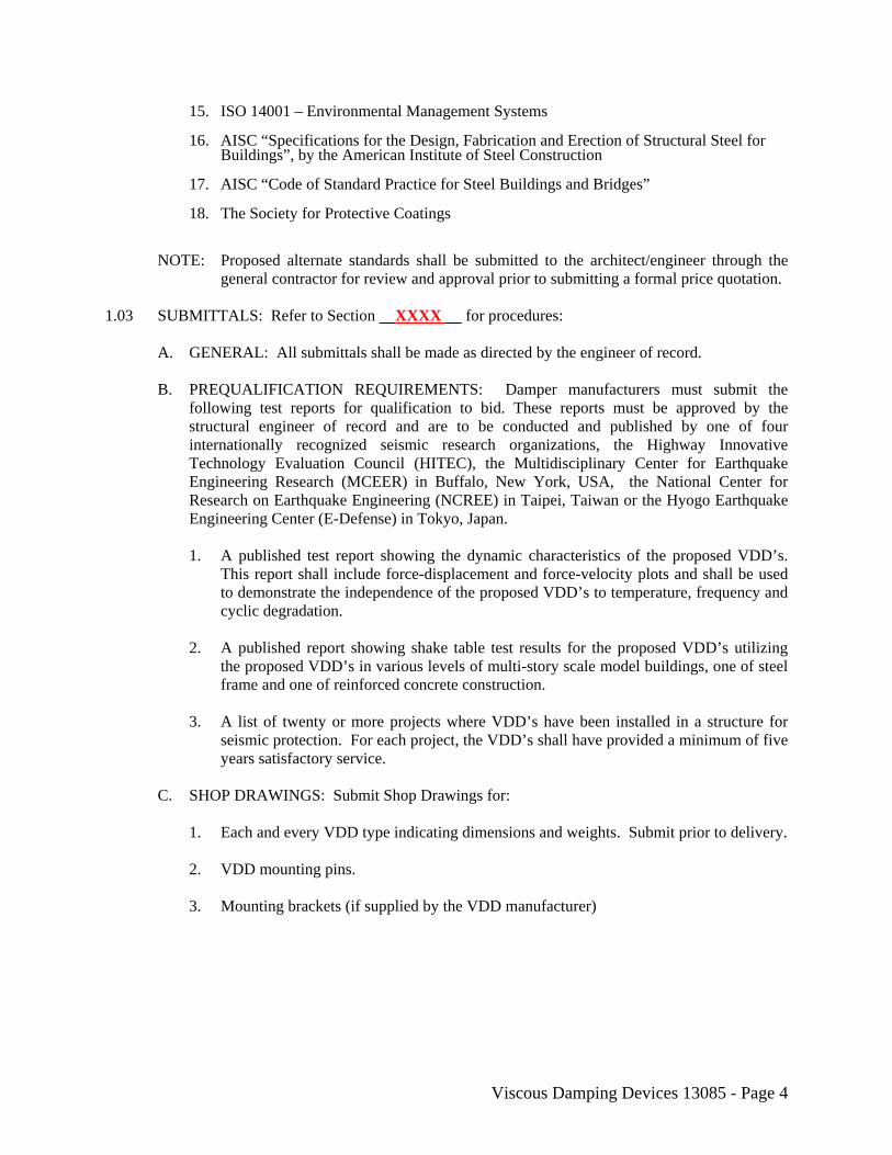
general contractor for review and approval prior to submitting a formal price quotation. 1.03 SUBMITTALS: Refer to Section XXXX for procedures: A. GENERAL: All submittals shall be made as directed by the engineer of record. B. PREQUALIFICATION REQUIREMENTS: Damper manufacturers must submit the
following test reports for qualification to bid. These reports must be approved by the structural engineer of record and are to be conducted and published by one of four internationally recognized seismic research organizations, the Highway Innovative Technology Evaluation Council (HITEC), the Multidisciplinary Center for Earthquake Engineering Research (MCEER) in Buffalo, New York, USA, the National Center for Research on Earthquake Engineering (NCREE) in Taipei, Taiwan or the Hyogo Earthquake Engineering Center (E-Defense) in Tokyo, Japan.
1. A published test report showing the dynamic characteristics of the proposed VDD’s.
This report shall include force-displacement and force-velocity plots and shall be used to demonstrate the independence of the proposed VDD’s to temperature, frequency and cyclic degradation.
2. A published report showing shake table test results for the proposed VDD’s utilizing
the proposed VDD’s in various levels of multi-story scale model buildings, one of steel frame and one of reinforced concrete construction.
3. A list of twenty or more projects where VDD’s have been installed in a structure for
seismic protection. For each project, the VDD’s shall have provided a minimum of five years satisfactory service.
C. SHOP DRAWINGS: Submit Shop Drawings for: 1. Each and every VDD type indicating dimensions and weights. Submit prior to delivery. 2. VDD mounting pins. 3. Mounting brackets (if supplied by the VDD manufacturer)
Viscous Damping Devices 13085 - Page 5
D. PRODUCT DATA: 1. VDD: Product Data shall include, but shall not be limited to manufacturer’s standard
product specifications, a list of production history for seismic dampers, and installation instructions.
2. Paint: Submit manufacturer’s literature and data. E. CERTIFICATIONS: Submit the following documents, written and signed by the Quality
Assurance Manager of the vendor. 1. A Certificate of Conformance (C of C) stating that all testing equipment has been
checked for accuracy by appropriate standards for the purpose of this specification and that all mill test reports for all steel to be used are on file at the vendor facility.
F. INSPECTION AND TEST REPORTS: Submit the following test reports, written and
signed by testing agency approved by the engineer of record. 1. Production VDD Test Reports: Submit test data for each production VDD within
fourteen (14) calendar days after the completion of testing of the subject VDD. 2. Final VDD Test Report: Submit the Final VDD Report, as described in this Section,
within twenty-eight (28) calendar days after the completion of all production VDD testing.
G. PROPOSED TEST PROCEDURES: Submit annotated and drafted illustrations of all
proposed test apparatus and procedures for tests required by this Section. Such illustrations shall be submitted and approved by the engineer of record and/or architect prior to the commencement of any testing.
1.04 DELIVERY, STORAGE AND HANDLING A. DELIVERY: Deliver production VDD’s to the job site in protective packaging for freight
and handling purposes. B. HANDLING: Handle VDD’s and components carefully to prevent damage, breaking,
denting or scoring. Do not deliver damaged VDD’s or components; replace with new. C. STORAGE: Store VDD’s in a clean place. Protect from dirt, fumes, construction debris and
physical damage. 1.05 WARRANTIES AND GUARANTEES
A written warranty of not less than 35 years shall be provided with the cost proposal along with a certification statement, signed by an officer of the manufacturer’s company and notarized, stating that a maintenance plan does not have to be purchased to activate the warranty. The manufacturer of the VDD’s specified herein shall have manufactured VDD’s of more than 150 kips output for a minimum of 20 years at the same manufacturing site, under the same company name as proposed to manufacture the VDD’s for this project.
Viscous Damping Devices 13085 - Page 6
PART 2 - PRODUCTS 2.01 VDD MATERIALS AND PARTS A. Except as specified herein, the materials, parts and processes used in the design and
manufacture of the unit shall conform to specifications and standards selected in the order of precedence established by MIL-STD-970. All materials and processes used shall be identified in vendor drawings by specifications or standards.
B. MATERIALS: All materials used in the manufacture of the unit shall be subject to approval
by the engineer of record. 1. Materials: Metallic Materials and Material Procurement Specifications shall be from
DOT/FAA/AR-MMPDS-11 or later revision. Materials shall have allowable stress values taken from MMPDS-11 or later revision. Unless suitably protected against electrolytic corrosion, dissimilar materials as defined in MIL-STD-889 shall not be used in contact with each other. Dissimilar metal joints shall not be permitted without a non-metallic separator or gasket of at least .06 inch thickness. The use of aluminum, aluminum alloys, magnesium, magnesium alloys, beryllium and beryllium alloys is prohibited. The use of non-stainless steel internally exposed to internal pockets of air or gas (as could occur in an internal reservoir, and plumbing to the reservoir) is prohibited.
2. Fungus Resistant Materials: Only non-nutrient materials shall be used in the unit. 3. Castings: All castings shall be prohibited for pressure vessel parts or any other parts
subjected to tensile or bending stresses, except for parts such as covers, handles, etc. whose failure would not affect the structural integrity or performance characteristics of the unit. Such casting may be Class 2B, subject to the approval of the engineer of record.
C. PARTS 1. VDD’s shall be constructed of maintenance-free designs only. Reservoirs, external
plumbing and/or fluid level indicators such as sight windows or pressure indicators that may leak are strictly prohibited.
2. Age Sensitive Parts: All non-metallic packings, seals, wipers or gaskets shall be of
non-age sensitive materials. 3. Piston rods and any part that slides relative to a seal shall be manufactured from
stainless steel only. Plating may be applied over the stainless steel if required by the type of fluid seal selected.
4. Operating fluid used in the dampers shall be non-toxic, non-flammable, and
cosmetically inert silicone per U.S. Federal Standard VV-D-1078. Petro-chemical fluids shall not be used unless specifically approved by the end-user.
5. The components of the damper that are pressure vessels are to be of non-tie rod type
construction, without externally supported heads or end caps. Welded construction or castings of any type are not permitted for pressure vessel construction.
Viscous Damping Devices 13085 - Page 7
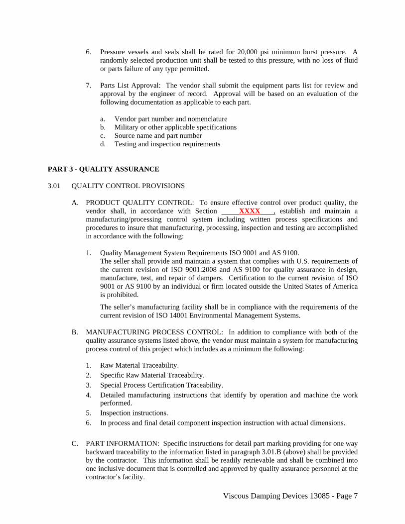
6. Pressure vessels and seals shall be rated for 20,000 psi minimum burst pressure. A randomly selected production unit shall be tested to this pressure, with no loss of fluid or parts failure of any type permitted.
7. Parts List Approval: The vendor shall submit the equipment parts list for review and
approval by the engineer of record. Approval will be based on an evaluation of the following documentation as applicable to each part.
a. Vendor part number and nomenclature b. Military or other applicable specifications c. Source name and part number d. Testing and inspection requirements PART 3 - QUALITY ASSURANCE 3.01 QUALITY CONTROL PROVISIONS A. PRODUCT QUALITY CONTROL: To ensure effective control over product quality, the
vendor shall, in accordance with Section XXXX , establish and maintain a manufacturing/processing control system including written process specifications and procedures to insure that manufacturing, processing, inspection and testing are accomplished in accordance with the following:
1. Quality Management System Requirements ISO 9001 and AS 9100.
The seller shall provide and maintain a system that complies with U.S. requirements of the current revision of ISO 9001:2008 and AS 9100 for quality assurance in design, manufacture, test, and repair of dampers. Certification to the current revision of ISO 9001 or AS 9100 by an individual or firm located outside the United States of America is prohibited.
The seller’s manufacturing facility shall be in compliance with the requirements of the current revision of ISO 14001 Environmental Management Systems.
B. MANUFACTURING PROCESS CONTROL: In addition to compliance with both of the
quality assurance systems listed above, the vendor must maintain a system for manufacturing process control of this project which includes as a minimum the following:
1. Raw Material Traceability. 2. Specific Raw Material Traceability. 3. Special Process Certification Traceability. 4. Detailed manufacturing instructions that identify by operation and machine the work
performed. 5. Inspection instructions. 6. In process and final detail component inspection instruction with actual dimensions.
C. PART INFORMATION: Specific instructions for detail part marking providing for one way
backward traceability to the information listed in paragraph 3.01.B (above) shall be provided by the contractor. This information shall be readily retrievable and shall be combined into one inclusive document that is controlled and approved by quality assurance personnel at the contractor’s facility.
Viscous Damping Devices 13085 - Page 8
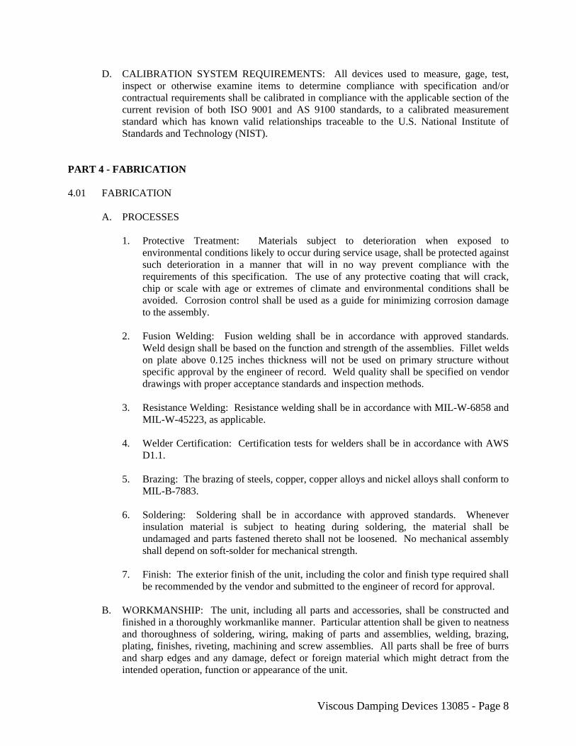
D. CALIBRATION SYSTEM REQUIREMENTS: All devices used to measure, gage, test, inspect or otherwise examine items to determine compliance with specification and/or contractual requirements shall be calibrated in compliance with the applicable section of the current revision of both ISO 9001 and AS 9100 standards, to a calibrated measurement standard which has known valid relationships traceable to the U.S. National Institute of Standards and Technology (NIST).
PART 4 - FABRICATION 4.01 FABRICATION A. PROCESSES 1. Protective Treatment: Materials subject to deterioration when exposed to
environmental conditions likely to occur during service usage, shall be protected against such deterioration in a manner that will in no way prevent compliance with the requirements of this specification. The use of any protective coating that will crack, chip or scale with age or extremes of climate and environmental conditions shall be avoided. Corrosion control shall be used as a guide for minimizing corrosion damage to the assembly.
2. Fusion Welding: Fusion welding shall be in accordance with approved standards.
Weld design shall be based on the function and strength of the assemblies. Fillet welds on plate above 0.125 inches thickness will not be used on primary structure without specific approval by the engineer of record. Weld quality shall be specified on vendor drawings with proper acceptance standards and inspection methods.
3. Resistance Welding: Resistance welding shall be in accordance with MIL-W-6858 and
MIL-W-45223, as applicable. 4. Welder Certification: Certification tests for welders shall be in accordance with AWS
D1.1. 5. Brazing: The brazing of steels, copper, copper alloys and nickel alloys shall conform to
MIL-B-7883. 6. Soldering: Soldering shall be in accordance with approved standards. Whenever
insulation material is subject to heating during soldering, the material shall be undamaged and parts fastened thereto shall not be loosened. No mechanical assembly shall depend on soft-solder for mechanical strength.
7. Finish: The exterior finish of the unit, including the color and finish type required shall
be recommended by the vendor and submitted to the engineer of record for approval. B. WORKMANSHIP: The unit, including all parts and accessories, shall be constructed and
finished in a thoroughly workmanlike manner. Particular attention shall be given to neatness and thoroughness of soldering, wiring, making of parts and assemblies, welding, brazing, plating, finishes, riveting, machining and screw assemblies. All parts shall be free of burrs and sharp edges and any damage, defect or foreign material which might detract from the intended operation, function or appearance of the unit.
Viscous Damping Devices 13085 - Page 9
4.02 SAFETY A. SAFETY: The design of the unit shall be such that all possible sources of danger to
personnel or equipment during assembly, disassembly, testing, operation and maintenance are minimized. Where required, precautionary measures shall be prominently and clearly indicated on the equipment.
4.03 MAINTAINABILITY A. MAINTAINABILITY: The unit shall be constructed to be maintenance free. The use of
reservoirs, external plumbing and/or fluid level indicators shall not be permitted. Each VDD shall be designed and constructed such that installation, removal and replacement, if necessary, shall be a simple process not requiring any special tools or methods. The use of fluid seals that require fluid weepage for lubrication are prohibited.
4.04 INTERCHANGEABILITY A. INTERCHANGEABILITY: All parts having the same manufacturer’s part number shall be
functionally and physically interchangeable. The vendor shall assign new part numbers when change numbers cause any of the following conditions:
1. Performance or durability is affected to such an extent that superseded items must be
discarded for reasons of safety or malfunctioning. 2. Parts, subassemblies of complete units are changed to such an extent that the
superseded and superseding items are not interchangeable. 3. Superseded parts are limited to use in specific articles or models of articles and the
superseding parts are not so limited to use.
When interchangeable repairable assemblies contain a non-interchangeable part, the part number re-identification of the non-interchangeable part, of it next assembly and all the progressive higher assemblies shall be changed up to and including the assembly where the interchangeability is re-established.
4.05 CHANGE CONTROL A. CHANGE CONTROL: After initial design completion and approval or initial hardware
delivery, whichever occurs first, any change or substitution of material, dimensions, processes or other characteristics must be approved by the engineer of record prior to incorporation. The vendor shall exercise the same configuration control over his suppliers.
4.06 IDENTIFICATION MARKING A. IDENTIFICATION MARKING: Units, subassemblies and parts shall be marked for
identification in accordance with MIL-STD-130.
Viscous Damping Devices 13085 - Page 10
4.07 SERIAL NUMBER ASSIGNMENT A. SERIAL NUMBER ASSIGNMENT: Sequential serial numbers shall be assigned to all
units in accordance with architect/engineer of record’s requirements. The individual number shall be assigned according to the vendor’s standard practice unless otherwise specified in the purchase order or contract.
PART 5 - DETAIL AND TECHNICAL REQUIREMENTS 5.01 FUNCTION A. FUNCTION: The VDD’s shall provide an output force in either tension or compression that
is directly proportional to the relative velocity between the two ends of the dampers. The damper output force varies only with velocity, and does not change with damper stroke position or orientation angle. The function of the dampers is to absorb earthquake energy, thereby reducing or eliminating damage to the building when an earthquake occurs.
B. FLUID MEDIUM: The unit shall use inert silicone fluid as the operating fluid medium
which shall comply with U.S. Federal Standard VV-D-1078. C. FLUID EXPANSION COMPENSATION: The unit shall contain provisions to allow for
thermal expansion and contraction of the fluid medium to prevent excessive buildup of internal high pressure or vacuum pressure.
D. SERVICING PROVISIONS: The dampers shall be maintenance and service free over a
period of at least 35 years and preferably over the expected life of the building. This means that no inspection, or fluid level verification, or refilling or replacement of fluid or any other parts shall be needed on any basis whatsoever. The dampers shall be designed and constructed so that installation, removal, or replacement, if necessary, shall be a simple process not requiring any special tools or methods.
E. ADJUSTMENT: The unit shall be designed to provide for a length adjustment of plus or
minus 0.25 inch. F. DIMENSIONS: The overall dimensions of the unit shall be held to a minimum consistent
with the requirements of this specification, and in no case shall they exceed the dimensions specified in Figure 1.
5.02 CONSTRUCTION A. GENERAL: The VDD unit shall be of corrosion protected construction with stainless steel
piston rod internally mounted. B. DESIGN LOADS 1. Axial Design Load: The maximum axial design load shall be XXXX kips tension or
compression with the rod fully extended, retracted or at any intermediate point.
Viscous Damping Devices 13085 - Page 11
2. Lateral Design Loads: The unit shall be designed to withstand a lateral acceleration of 1 g in any direction in any position of rod extension/retraction.
3. Fluid Pressure: The unit shall be designed to withstand the following internal pressure: a. Proof: 200 percent of maximum operating pressure. b. Burst: 250 percent of maximum operating pressure, but not less than 20,000 psi. 4. Factors of Safety: Minimum factors of safety for the unit shall be 2.0 limit. The unit
shall be such that no yielding will result from the application of limit loads. Limit loads shall include the effects of load factors included herein.
5.03 PERFORMANCE A. DAMPING COEFFICIENT: The unit shall operate with a damping coefficient in both
directions of travel as shown in Figure 2. The normal operating force developed by the unit over the design range of velocity shall always fall within the envelope as shown in Figure 2.
B. DUTY CYCLES: The unit shall be designed to the amplitude, frequency and time
requirements of the following wind load and seismic loading duty cycles. 1. Wind Load Duty Cycle: 0 to XXXX in. amplitude at XXXX Hz for XXXX cycles per
amplitude) at XXXX Hz for XXXX cycles (average) per year. C. MAXIMUM/MINIMUM OPERATING TEMPERATURES: The unit shall be capable of
operating at the energy levels, time and the environmental conditions specified herein, without degradation of performance or life as a result of maximum/minimum operating temperature.
D. LEAKAGE: The use of fluid seals that require fluid weepage for lubrication are prohibited.
Under non-operating conditions, static seals shall not leak externally. When subjected to proof pressure for three (3) minutes, the unit shall show no visible evidence of external leakage.
E. STROKE: The unit shall be capable of meeting the performance requirements of 5.03 A and
C, when cycled about any point within the full stroke of the unit. 5.04 LIFE A. LIFE: The unit shall be designed to guarantee a minimum reuse of one maximum capable
seismic event before requiring refurbishment.
Viscous Damping Devices 13085 - Page 12
5.05 ENVIRONMENTAL CONDITIONS A. AMBIENT OPERATING TEMPERATURE: When installed, the unit shall be capable of
operating in an ambient air temperature from +20F to +130F. B. ATMOSPHERIC PRESSURE: The unit shall operate at essentially sea level pressure (760
±50mm mercury). C. HUMIDITY: The unit shall be designed to withstand relative humidity up to 100 percent,
including condensation due to temperature change. D. OTHER ATMOSPHERIC ELEMENTS: The unit shall be designed to withstand any of the
probable combinations of the following atmospheric elements: rain, snow, sleet, hail, ice, fog, smoke, wind, ozone, sunshine, sand and dust, and salt atmosphere.
PART 6 - TESTING 6.01 TESTING OF VISCOUS DAMPING DEVICE UNITS A. PRODUCTION UNIT TESTING: 1. Purpose: Production unit testing shall be conducted in order to verify the following: a. The general quality and manufacturing consistency of each of the production units. b. The general consistency of all production units in terms of their performance
characteristics to meet the requirements of the contract documents. 2. Acceptance Criteria: (1) No visible leakage or signs of physical deterioration or degradation in
performance shall be observed during and after the series of tests. There shall be no signs of yielding or permanent deformation, or re-torquing of parts.
(2) The force-velocity results from the tests both in tension and in compression,
adjusted for expected variations due to temperature and number of stroke cycles shall fall entirely within the upper and lower bound curves (Figure 2) as used for the final design of the damped structure.
3. Sequence of Testing: a. Quality Assurance Tests: Production units shall be subjected to and pass the
following sequence of quality assurance tests:
(1) Proof load test: An internal pressure shall be applied to each VDD that shall be equivalent to 150% of the maximum damper load (each production unit). This pressure shall be maintained for 180 seconds.
Viscous Damping Devices 13085 - Page 13
(2) High Level Proof Load Test: One out of every fifty production units, or a minimum of two (2) units, shall have an internal pressure of 20,000 psi applied. This pressure shall be maintained for 180 seconds.
(3) Life Cycle Test: One out of every fifty production units, or a minimum of two
(2) units, shall be cycled through its full end to end displacement for a total of 60 cycles. The cyclic velocity is expected to be much slower than the design maximum velocity and shall depend on the capacity of the approved testing apparatus.
b. Performance Verification Tests: (1) Production unit testing shall be conducted on all units in order to verify the
performance consistency of each production unit. These tests shall be performed in the tension and compression directions and shall verify the force velocity characteristics of the damper. Tests are to be performed at 100% of DBE velocity as determined from dynamic analysis of the structure for 3 cycles. The test results shall fall entirely within the upper and lower bound curves (+/- 15%). The force, displacement and time measurements shall be accurately obtained and recorded. Force-velocity plots shall be constructed from this data.
(2) For time/cost savings, testing in the compression direction only may be
proposed, provided the damper manufacturer can substantiate the balanced nature of fluid orificing in each direction. The use of valves and/or reservoirs or accumulators are not considered a balanced method and will require testing in both directions.
Viscous Damping Devices 13085 - Page 14
FIGURE 1 MAXIMUM ENVELOPE DAMPER DRAWING
FIGURE 2 FORCE-VELOCITY DAMPER OUTPUT ENVELOPE
Page 1
Sample Technical Specifications For Shock Transmission Units
And Lock-up Devices
2017
Page 2
TABLE OF CONTENTS Part 1 – General Page
1.01 Description ................................................................................................................ 3 1.02 References ................................................................................................................. 3 1.03 Submittals ................................................................................................................. 4 1.04 Delivery, Storage and Handling ................................................................................ 5 1.05 Warranties and Guarantees ....................................................................................... 5 Part 2 - Products
2.01 Materials and Parts ................................................................................................... 5 Part 3 - Quality Assurance
3.01 Quality Control Provisions ....................................................................................... 6 Part 4 - Fabrication
4.01 Fabrication ................................................................................................................ 7 4.02 Safety ........................................................................................................................ 8 4.03 Maintainability .......................................................................................................... 8 4.04 Interchangeability ..................................................................................................... 8 4.05 Change Control ......................................................................................................... 9 4.06 Identification Marking .............................................................................................. 9 4.07 Serial Number Assignment ....................................................................................... 9 Part 5 - Detail and Technical Requirements
5.01 Function .................................................................................................................... 9 5.02 Construction .............................................................................................................. 9 5.03 Performance ............................................................................................................ 10 5.04 Life .......................................................................................................................... 10 5.05 Environmental Conditions ...................................................................................... 11 Part 6 - Testing
6.01 Testing of Devices / Units ...................................................................................... 11
Page 3
SHOCK TRANSMISSION UNITS PART 1 - GENERAL 1.01 DESCRIPTION: Shock Transmission Unit (STU) and Lock-up Device (LUD) shall be
interchangeable descriptions throughout this specification. The purpose of these devices is to function as a load transfer path for dynamic (high velocity) inputs in both tension and compression directions, regardless of thermal movement location. During thermal excursions (extremely slow speeds) these devices are to provide minimal resistance to such movement.
A. WORK IN THIS SECTION: Principal items include: 1. Preparation of shop drawings, test reports, designing, fabrication, testing, handling and
shipping to the site.
2. Extent of fabrication of Shock Transmission Units (STU) work of this section is indicated by the requirements of this section.
3. Production Units: Provide Shock Transmission Units (STU) in accordance with the
specifications. B. RELATED WORK NOT IN THIS SECTION: Installation of units shall be by others. 1.02 REFERENCES A. STANDARDS: Conform to the applicable provisions of the current editions of the
following standards, except as indicated otherwise on the drawings or the specifications:
1. Title 24, Part 2, CCR, 1989 Amendments
2. ASTM E4 - Load Verification of Testing Machines
3. ASTM A36 - Specification for Structural Steel
4. ASTM A325 - Specification for High Strength Steel Bolts
5. ASTM A570 - Specification for Structural Sheet Steel
6. U.S. Standard DOT/FAA/AR-MMPDS-11 or later revision, Metallic Materials – Properties, Development, and Standardization
7. AWS D1.5 - Structural Welding Code of the American Welding Society
8. AMS-W-6858 - Welding, Resistance: Spot and Seam
9. AWS- C3.4, C3.5, C3.6 - Brazing of Steels, Copper, Copper Alloys, Nickel Alloys, Aluminum and Aluminum Alloys
10. AWS- C1.4, C1.4M - Welding, Spot, Hardenable
11. NAV SEA S9074-AQ-GIB-010/248 – Welding and Brazing Procedure and Performance Qualifications
12. AMS-STD-2175 - Classification and Inspection of Casting
13. ANSI/ISO/ASQ 9001(ISO 9001:2008) - Quality Management Systems Requirements
14. SAE AS 9100 Quality Management System
Page 4
15. ISO 14001 – Environmental Management Systems
16. AISC “Specifications for the Design, Fabrication and Erection of Structural Steel for Buildings,” by the American Institute of Steel Construction
17. AISC “Code of Standard Practice for Steel Buildings and Bridges” 18. The Society for Protective Coatings NOTE: Proposed alternate standards shall be submitted to the architect/engineer through the
general contractor for review and approval prior to submitting a formal price quotation. 1.03 SUBMITTALS A. GENERAL: All submittals shall be made as directed by the engineer of record. B. SHOP DRAWINGS: Shop Drawings shall include, but shall not be limited to, fabrication
2. All steel mounting and connecting hardware which is integral with the STU. C. PRODUCT DATA:
1. STU: Product Data shall include, but shall not be limited to manufacturer's product specifications, a list of production history for seismic dampers and STU’s, and installation instructions.
2. All materials and components used in manufacture: Submit product data for review and approval.
3. Paint: Submit manufacturer's literature and data, including evidence of conformance to the requirements of regulatory agencies, printed preparation and application instructions for each substrate and certified laboratory tests showing compliance with the property and test requirements specified.
D. CERTIFICATIONS: The following documents shall be kept on file at the manufacturer’s
facilities:
1. Certification that all testing equipment has been checked for accuracy by appropriate standards for the purpose of this specification.
2. Certified mill test reports for all steel to be used. E. INSPECTION AND TEST REPORTS: Submit the following test reports. 1. Final STU Test Report: Submit the Final STU Report, as described in this Section,
within fourteen (14) calendar days after the completion of all production STU testing.
F. PROPOSED TEST PROCEDURES: Submit annotated and drafted illustrations of all proposed test apparatus and procedures for tests required by this Section. Such illustrations shall be submitted and approved by the engineer of record and/or architect prior to the commencement of any testing.
Page 5
1.04 DELIVERY, STORAGE AND HANDLING A. DELIVERY: Deliver production STUs to the job site in protective packaging for freight and
handling purposes. B. HANDLING: Handle STUs and components carefully to prevent damage, breaking, denting
or scoring. Do not deliver damaged STUs or components; replace with new. C. STORAGE: Store STUs in a clean place. Protect from dirt, fumes, construction debris and
physical damage. 1.05 WARRANTIES AND GUARANTEES
A written warranty of not less than 10 years shall be provided with the cost proposal, along with certification that a maintenance plan does not have to be purchased to activate the warranty. The manufacturer of the STUs specified herein shall have manufactured STUs of more than 250 kip output for a minimum of 20 years at the same manufacturing site proposed to manufacture the STUs for this project. Submit a production history report as specified in Section 1.03.C.1.
PART 2 - PRODUCTS 2.01 STU MATERIALS AND PARTS A. Except as specified herein, the materials, parts and processes used in the design and
manufacture of the unit shall conform to specifications and standards selected in the order of precedence established by MIL-STD-970. All materials and processes used shall be identified in vendor drawings by specifications or standards.
B. MATERIALS: All materials used in the manufacture of the unit shall be subject to approval
by the engineer of record. The vendor may be required to substantiate suitability of the material.
1. Materials: Metallic Materials and Material Procurement Specifications shall be from
DOT/FAA/AR-MMPDS-11 or later revision. Materials shall have allowable stress values taken from MMPDS-11 or later revision. Unless suitably protected against electrolytic corrosion, dissimilar materials as defined in MIL-STD-889 shall not be used in contact with each other. Dissimilar metal joints shall not be permitted without a non-metallic separator or gasket of at least .06 inch thickness. The use of aluminum, aluminum alloys, magnesium, magnesium alloys, beryllium and beryllium alloys is prohibited. The use of non-stainless steel internally exposed to internal pockets of air or gas (as could occur in an internal reservoir, and plumbing to the reservoir) is prohibited.
2. Fungus Resistant Materials: Only non-nutrient materials shall be used in the unit. 3. Castings: All castings shall be prohibited for pressure vessel parts or any other parts
subjected to tensile or bending stresses, except for parts such as covers, handles, etc. whose failure would not affect the structural integrity or performance characteristics of the unit. Such casting may be Class 2B, subject to the approval of the engineer of record.
Page 6
C. PARTS 1. STUs shall be constructed of maintenance-free designs only. Reservoirs, external
plumbing and/or fluid level indicators are not permitted. 2. Age Sensitive Parts: All non-metallic packings, seals, wipers or gaskets shall be of
non-age sensitive materials. 3. Piston rods and any part that slides relative to a seal shall be manufactured from high-
strength stainless steel only. Plating may be applied over the stainless steel if required by the type of fluid seal selected.
4. Operating fluid used in the units shall be non-toxic, non-flammable, and cosmetically
inert silicone fluid, certified to U.S. Federal Standard VV-D-1078, and have a maximum viscosity of 20,000 centistokes. Petro-chemical fluids shall not be used unless specifically approved by the end-user.
5. The components of the units that are pressure vessels are to be of non-tie rod type
construction, without externally supported heads or end caps. Welded construction or castings of any type are not permitted for pressure vessel construction.
6. Pressure vessels and seals shall be rated for 20,000 psi minimum burst pressure.
Calculations shall be submitted to demonstrate the unit’s ability to meet this requirement.
7. Parts List Approval: The vendor shall submit the equipment parts list for review and
approval by the engineer of record. Approval will be based on an evaluation of the following documentation as applicable to each part.
a. Vendor part number and nomenclature
b. Military or other applicable specifications
c. Source name and part number
d. Testing and inspection requirements
PART 3 - QUALITY ASSURANCE 3.01 QUALITY CONTROL PROVISIONS A. PRODUCT QUALITY CONTROL: To ensure effective control over product quality, the
vendor shall establish and maintain a manufacturing/processing control system including written process specifications and procedures to insure that manufacturing, processing, inspection and testing are accomplished in accordance with the following:
1. Quality Management System Requirements ISO 9001 and AS 9100.
The seller shall provide and maintain a system that complies with U.S. requirements of the current revision of ISO 9001:2008 and AS 9100 for quality assurance in design, manufacture, test, and repair of dampers. Certification to the current revision of ISO 9001 or AS 9100 by an individual or firm located outside the United States of America is prohibited.
The seller’s manufacturing facility shall be in compliance with the requirements of the current revision of ISO 14001 Environmental Management Systems.
Page 7
B. MANUFACTURING PROCESS CONTROL: In addition to compliance with both the quality assurance systems listed above, the vendor must maintain a system for manufacturing process control of this project which includes as a minimum the following:
1. Raw material traceability
2. Specific raw material traceability
3. Special process certification traceability
4. Detailed manufacturing instructions that identify by operation and machine the work performed
5. Inspection instructions
6. In process and final detail component inspection instruction with actual dimensions C. PART INFORMATION: Specific instructions for detail part marking providing for one way
backward traceability to the information listed in paragraph 3.01.B (above) shall be provided by the contractor. This information shall be readily retrievable and shall be combined into one inclusive document that is controlled and approved by quality assurance personnel at the contractor's facility.
D. CALIBRATION SYSTEM REQUIREMENTS: All devices used to measure, gage, test,
inspect or otherwise examine items to determine compliance with specification and/or contractual requirements shall be calibrated in compliance with the applicable section of the current revision of both ISO 9001 and AS 9100 standards, to a calibrated measurement standard which has known valid relationships traceable to the U.S. National Institute of Standards and Technology (NIST).
PART 4 - FABRICATION 4.01 FABRICATION A. PROCESSES: All processes used in the manufacture of the unit shall be subject to approval
by the engineer of record. 1. Protective Treatment: Materials subject to deterioration when exposed to
environmental conditions likely to occur during service usage, shall be protected against such deterioration in a manner that will in no way prevent compliance with the requirements of this specification. The use of any protective coating that will crack, chip or scale with age or extremes of climate and environmental conditions shall be avoided.
2. Fusion Welding: Fusion welding shall be in accordance with approved standards.
Weld design shall be based on the function and strength of the assemblies. Fillet welds on plate above 0.125 inches thickness will not be used on primary structure without specific approval by the engineer of record. Weld quality shall be specified on vendor drawings with proper acceptance standards and inspection methods.
Page 8
3. Resistance Welding: Resistance welding shall be in accordance with MIL-W-6858 and MIL-W-45223, as applicable.
4. Welder Certification: Certification tests for welders shall be in accordance with MIL-
STD-248. 5. Brazing: The brazing of steels, copper, copper alloys and nickel alloys shall conform to
MIL-B-7883. 6. Soldering: Soldering shall be in accordance with approved standards. Whenever
insulation material is subject to heating during soldering, the material shall be undamaged and parts fastened thereto shall not be loosened. No mechanical assembly shall depend on soft-solder for mechanical strength.
7. Finish: The exterior finish of the unit, including the color and finish type required shall
be recommended by the vendor and submitted to the engineer of record for approval. B. WORKMANSHIP: The unit, including all parts and accessories, shall be constructed and
finished in a thoroughly workmanlike manner. Particular attention shall be given to neatness and thoroughness of soldering, wiring, making of parts and assemblies, welding, brazing, plating, finishes, riveting, machining and screw assemblies. All parts shall be free of burrs and sharp edges and any damage, defect or foreign material which might detract from the intended operation, function or appearance of the unit.
4.02 SAFETY A. SAFETY: The design of the unit shall be such that all possible sources of danger to
personnel or equipment during assembly, disassembly, testing, operation and maintenance are minimized. Where required, precautionary measures shall be prominently and clearly indicated on the equipment.
4.03 MAINTAINABILITY A. MAINTAINABILITY: The unit shall be constructed to be maintenance free. The use of
reservoirs, external plumbing and/or fluid level indicators shall not be permitted. Each STU shall be designed and constructed such that installation, removal and replacement, if necessary, shall be a simple process not requiring any special tools or methods.
4.04 INTERCHANGEABILITY A. INTERCHANGEABILITY: All parts having the same manufacturer's part number shall be
functionally and physically interchangeable. The vendor shall assign new part numbers when change numbers cause any of the following conditions:
1. Performance or durability is affected to such an extent that superseded items must be
discarded for reasons of safety or malfunctioning. 2. Parts, subassemblies of complete units are changed to such an extent that the
superseded and superseding items are not interchangeable. 3. Superseded parts are limited to use in specific articles or models of articles and the
superseding parts are not so limited to use.
Page 9
When interchangeable repairable assemblies contain a non-interchangeable part, the part number re-identification of the non-interchangeable part, of its next assembly and all the progressive higher assemblies shall be changed up to and including the assembly where the interchangeability is re-established.
4.05 CHANGE CONTROL A. CHANGE CONTROL: After initial design completion and approval or initial hardware
delivery, whichever occurs first, any change or substitution of material, dimensions, processes or other characteristics must be approved by the engineer of record prior to incorporation. The vendor shall exercise the same configuration control over his suppliers.
4.06 IDENTIFICATION MARKING A. IDENTIFICATION MARKING: Units, subassemblies and parts shall be marked for
identification in accordance with MIL-STD-130. 4.07 SERIAL NUMBER ASSIGNMENT A. SERIAL NUMBER ASSIGNMENT: Sequential serial numbers shall be assigned to all
units in accordance with architect/engineer of record's requirements. The individual number shall be assigned according to the manufacturer standard practice unless otherwise specified in the purchase order or contract.
PART 5 - DETAIL AND TECHNICAL REQUIREMENTS 5.01 FUNCTION A. FUNCTION: The STUs shall provide an output force in either tension or compression that
is directly caused by a relative velocity input between the two ends of the unit. The unit output force varies only with velocity, and does not change with orientation angle.
B. FLUID MEDIUM: The unit shall use inert silicone fluid as the operating fluid medium
which shall comply with U.S. Federal Standard VV-D-1078, and have a maximum viscosity of 20,000 centistokes.
C. SERVICING PROVISIONS: The STU unit shall be designed and constructed to be
maintenance free for the expected life of the STU. D. ADJUSTMENT: The unit shall be designed to provide for a length adjustment of plus or
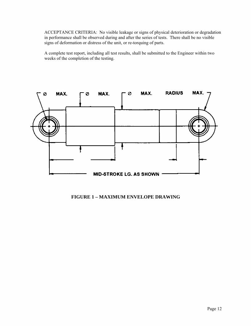
minus 0.25 inch. E. DIMENSIONS: The overall dimensions of the unit shall be held to a minimum consistent
with the requirements of this specification, and in no case shall they exceed the dimensions specified in Figure 1.
5.02 CONSTRUCTION A. GENERAL: The STU unit shall be of corrosion protected construction with stainless steel
piston rod internally mounted.
Page 10
B. DESIGN LOADS 1. Axial Design Load: The maximum axial design load shall be XXX kip tension or
compression with the rod fully extended, retracted or at any intermediate point. 2. Lateral Design Loads: The unit shall be designed to withstand a lateral acceleration of
1 g in any direction in any position of rod extension/retraction. 3. Fluid Pressure: Unit shall be designed to withstand the following internal pressure:
a. Proof: 200 percent of maximum operating pressure.
b. Burst: 250 percent of maximum operating pressure, but not less than 20,000psi. 4. Factors of Safety: Minimum factors of safety for the unit shall be 2.0 limit. The unit
shall be such that no yielding will result from the application of limit loads. Limit loads shall include the effects of load factors included herein.
5.03 PERFORMANCE A. DUTY CYCLES: The unit shall be designed to the amplitude, frequency and time
requirements of the following wind load and seismic loading duty cycles. 1. Wind Load Duty Cycle: No less than 10% maximum rated STU load applied in
extension and compression directions for XXXX cycles per year. 2. Seismic Loading Duty Cycle: No less than 50% maximum rated STU load applied in
extension and compression directions for 5 reversed cycles (average) per year. B. MAXIMUM/MINIMUM OPERATING TEMPERATURES: The unit shall be capable of
operating at the energy levels, time and the environmental conditions specified herein, without degradation of performance or life as a result of maximum/minimum operating temperature.
C. LEAKAGE: The use of fluid seals that require fluid weepage for lubrication are prohibited.
Under non-operating conditions, static seals shall not leak externally. When subjected to proof pressure for two (2) minutes, the unit shall show no visible evidence of external leakage.
5.04 LIFE A. LIFE: The unit shall be designed to guarantee a minimum reuse of one maximum capable
seismic event before requiring refurbishment.
Page 11
5.05 ENVIRONMENTAL CONDITIONS A. AMBIENT OPERATING TEMPERATURE: When installed, the unit shall be capable of
operating in an ambient air temperature from -20F to +130F. B. ATMOSPHERIC PRESSURE: The unit shall operate at essentially sea level pressure (760 50mm mercury). C. HUMIDITY: The unit shall be designed to withstand relative humidity up to 100%,
including condensation due to temperature change. D. OTHER ATMOSPHERIC ELEMENTS: The unit shall be designed to withstand any of the
probable combinations of the following atmospheric elements: rain, snow, sleet, hail, ice, fog, smoke, wind, ozone, sunshine, sand and dust, and salt atmosphere.
PART 6 - TESTING 6.01 TESTING A. QUALITY ASSURANCE TESTING OF SHOCK TRANSMISSION UNIT (STU/LUD)
1. STATIC PROOF LOAD TEST: An internal pressure shall be applied to each STU that shall be equivalent to 150% of the maximum STU load. This pressure shall be maintained for 180 seconds. This test is meant to verify the pressure vessel integrity of every unit.
2. HIGH LEVEL PROOF LOAD TEST: One out of every fifty production units, or a
minimum of two (2) units, shall have an internal pressure of 20,000 psi applied. This pressure shall be maintained for 180 seconds. This test is meant to verify the strength and integrity of the pressure vessel design.
3. STROKE TEST: One out of every fifty production units, or a minimum of two (2)
units, shall be stroked through the entire range of motion. This test is meant to verify stroke capacity of the device design
4. TRANSLATION TEST AT LOW VELOCITY (Velocity ≤ 0.005 in/sec): Each unit
shall be stroked over a portion of the movement range of the STU in both tension and compression. The maximum reaction force shall not exceed 10% of the rated load (maximum design force) in either tension or compression. This test is meant to simulate typical thermal movement of the STU and is to be performed on 100% of all devices.
5. PROOF LOAD TEST AT HIGH VELOCITY (Velocity ≥ 0.5 in/sec): The horizontal
load shall be applied at a sufficient rate to simulate a shock load. The STU shall be tested in both tension and compression. The maximum reaction force shall not be lower than the maximum STU design force. This test is meant to simulate the peak load due to an earthquake, or other high speed dynamic movement of the STU and is to be performed on 100% of all devices.
Page 12
ACCEPTANCE CRITERIA: No visible leakage or signs of physical deterioration or degradation in performance shall be observed during and after the series of tests. There shall be no visible signs of deformation or distress of the unit, or re-torquing of parts.
A complete test report, including all test results, shall be submitted to the Engineer within two weeks of the completion of the testing.