Centre d’expertise en analyse environnementale du Québec Sampling Guide for Environmental Analysis English version of the French edition of September 15, 2016 Booklet 4 Sampling of Atmospheric Emissions from Stationary Sources
Transcript
Centre d’expertise en analyse environnementale du Québec
Sampling Guide for Environmental Analysis
English version of the French edition of September 15, 2016
Booklet 4
Sampling of Atmospheric Emissions from Stationary Sources
Note to the reader: The information pertaining to registered trademarks or commercial products is used only as a guide and can be substituted for any equivalent product.
For additional information on the activities of Centre d’expertise en analyse environnementale du Québec or to obtain our documents, please see our website : www.ceaeq.gouv.qc.ca or contact us at: Centre d’expertise en analyse environnementale du Québec 2700, rue Einstein, bureau E.2.220 Québec (Québec) G1P 3W8 Telephone: 418-643-1301 Fax: 418-528-1091 Email: [email protected]
The series Sampling Guide for Environmental Analysis currently includes the following: Cahier 1 Généralités [General Information] Cahier 5 Échantillonnage des sols [Soil Sampling] Cahier 2 Échantillonnage des rejets liquides Booklet 6 Forage Sampling for Fluoride Analysis [Sampling of Liquid Discharges] Booklet 3 Groundwater Sampling Booklet 7 Flow Measurement Methods in Open Channels Booklet 4 Sampling of Atmospheric Emissions Cahier 8 Échantillonnage des matières dangereuses from Stationary Sources [Sampling of Hazardous Materials]
Booklet 4 – Sampling of Atmospheric Emissions from Stationary Sources III
FOREWORD Booklet 4 of the Sampling Guide for Environmental Analysis covers sampling of atmospheric emissions from stationary sources. It is intended for people who work in the field of environmental sampling or who use such services. The booklet was written to standardize their understanding of sampling atmospheric emissions and assist their work in the field. It in no way changes requirements specified in regulations or authorizations. Booklet 4 has undergone an in-depth review. Sections on planning and conducting a sampling campaign as well as the content of the sampling report have been enhanced and the sampling methods fully updated. Samplers using this booklet should be familiar with the general information in Cahier 1, Généralités (Booklet 1, General Information), which covers the basics of planning a sampling campaign. It also outlines the technical procedures that should be followed to ensure quality control, health and safety, and sample integrity. Comments submitted by users since Booklet 4 was first published were taken into account in the review process in order to improve the content and adapt it in light of recent developments. Experts in stationary source sampling and associations with an interest in this area were consulted and we extend our sincere thanks for their contribution. We would also like to thank the authors of the previous editions, as well as everyone who collaborated directly or indirectly in preparing this edition. Their opinions and comments played a key role in the preparation of this edition of Booklet 4 of the Sampling Guide for Environmental Analysis. Please send any comments and questions on this booklet to [email protected].
IV Booklet 4 – Sampling of Atmospheric Emissions from Stationary Sources
About the Sampling Guide for Environmental Analysis
The Sampling Guide for Environmental Analysis is series of booklets that deal specifically with sampling a range of environments. It describes best practices for planning and performing sampling work in order to ensure sample quality and the validity of the resulting scientific data. It is a reference work providing general information on recognized sampling practices. Regulations, directives, policies and other documents produced by Ministère du Développement durable, de l’Environnement et de la Lutte contre les changements climatiques (MDDELCC) refer to one or more booklets in the series. Centre d’expertise en analyse environnemental du Québec (CEAEQ), the Ministry authority responsible for the Sampling Guide for Environmental Analysis, publishes the booklets and coordinates the process of updating them. It ensures their uniformity and regulatory compliance. When approval from the Ministry is required under one of the sampling booklets, the request is submitted to the regional branch concerned.
Booklet 4 – Sampling of Atmospheric Emissions from Stationary Sources V
GLOSSARY
Deviation A deviation refers to the failure to comply with a sampling method for various reasons. A sampling method may have to be modified because of the particular nature of an emission point (for example, if it is impossible to properly install the sampling equipment, the temperature of the gas streams is too high, or their speed too low). In such cases, prior approval from the Ministry or the authority concerned is required. A deviation can also occur during sampling (for example, collection of a volume of gas smaller than that required by the methodology). In such cases, the deviation must be recorded and clearly explained on the field data sheets and included in the report.
Emission point Stack, vent, fan, or any other opening that may release emissions into the air. A sampling campaign may involve a number of emission points.
Environmental compliance verification
Process to verify compliance with a regulatory requirement or a requirement included in an authorization under Québec’s Environment Quality Act.
Isokinetic sampling
Sampling is isokinetic when the linear velocity of the gas entering the sampling nozzle is equal to that of the undisturbed gas stream at the sampling point.
Ministry
Ministère du Développement durable, de l’Environnement et de la Lutte contre les changements climatiques.
Qualified personnel
Personnel with the training and experience described in Lignes directrices concernant les prélèvements des émissions atmosphériques en provenance de sources fixes (Guidelines for Sampling of Atmospheric Emissions from Stationary Sources), DR-12-AIR-01, available on the CEAEQ website.
Reference conditions “R”
Reference conditions specified in Québec legislation.
VI Booklet 4 – Sampling of Atmospheric Emissions from Stationary Sources
Source operator
Operator of the emission source being sampled.
Sampling site
Location of the emission point where samples are collected. Sampling methods include instructions for choosing the sampling site.
Sampler
The team that collects the samples during a sampling campaign; the team may be from a regulatory body or an external sampling firm or be employed by the operator of the emission source targeted by the sampling campaign.
Campaign site
Location where the sampling campaign is carried out (plant and the municipality in which it is located).
Stationary emission source
Activity, equipment, or process, other than a mobile vehicle, aircraft, ship, or locomotive, that generates emissions; a stationary source may have one or more emission points.
Test
Collection of a sample, with its duration depending on the sampling method.
Booklet 4 – Sampling of Atmospheric Emissions from Stationary Sources VII
ACRONYMS AND SYMBOLS
ASTM: American Society for Testing Material Br2: Bromine CB: Chlorobenzene compounds
CEAEQ: Centre d’expertise en analyse environnementale du Québec
(CH3)2S: Dimethyl sulfide
(CH3)2S2: Dimethyl disulfide
CH3SH: Methanethiol
Cl2: Chlorine CEMS: Continuous emission monitoring system CMM: Communauté métropolitaine de Montréal DRE: Destruction and removal efficiency EQA: Environment Quality Act
ES: European standard FS: French standard FTIR: Fourier transform infrared spectrophotometer ∆H: Drop in pressure at orifice meter H2S: Hydrogen sulphide
H2SO4: Sulfuric acid HBr: Hydrobromic acid or hydrogen bromide
HCl: Hydrochloric acid or hydrogen chloride
HF: Hydrofluoric acid or hydrogen fluoride ISO/CEI 17025: General prescriptions concerning the jurisdiction of calibration and testing
laboratories distributed jointly by the International Organization for Standardization and the International Electrotechnical Commission.
VIII Booklet 4 – Sampling of Atmospheric Emissions from Stationary Sources
NCASI: National Council for Air and Stream Improvement ∆P: Differential pressure of stack gases PAH: Polycyclic aromatic hydrocarbons PC: Phenolic compounds
PCB: Polychlorinated biphenyls PCDD and PCDF: Polychlorinated dibenzodioxins and polychlorinated dibenzofurans
PM2.5: Fine particulates matter or particulates matter with an aerodynamic diameter of less than 2.5 microns
PM10: Particulates matter with an aerodynamic diameter of less than 10 microns QA: Quality assurance
QA/QC: Quality assurance and control
QC: Quality control
SO2: Sulfur dioxide
SO3: Sulfur trioxide
US EPA: United States Environmental Protection Agency
Booklet 4 – Sampling of Atmospheric Emissions from Stationary Sources IX
TABLE OF CONTENTS
FOREWORD ......................................................................................................................... III
GLOSSARY ............................................................................................................................. V
ACRONYMS AND SYMBOLS .......................................................................................... VII
3. PRINCIPLES OF QUALITY ASSURANCE AND CONTROL .................................. 4
3.1 QA/QC in the Planning and Preparation Stages .......................................................... 4 3.2 QA/QC during Sampling ............................................................................................. 4 3.3 Post-test QA/QC .......................................................................................................... 5 3.4 Sampling Report QA/QC ............................................................................................. 6
4. DATA RECORDING (TRACEABILITY) ..................................................................... 6
4.1 Equipment Calibration Certificates ............................................................................. 6 4.2 Data and Sample Collection ........................................................................................ 6 4.3 Data retention ............................................................................................................... 7
5. CALIBRATION AND VERIFICATION ........................................................................ 7
5.1 Calibration and Verification of Sampling Equipment ................................................. 8 5.2 Calibration and Verification of Gas Analyzers ........................................................... 8
6. PLANNING A SAMPLING CAMPAIGN ...................................................................... 9
6.1 Planning by the Emission Source Operator ............................................................... 10 6.1.1 Context and objective of the sampling campaign ............................................. 10 6.1.2 Parameters and substances or contaminants to be sampled .............................. 10 6.1.3 Description of the emission source ................................................................... 11 6.1.4 Identification and description of emission points ............................................. 11 6.1.5 Identification of scrubbing equipment .............................................................. 12 6.1.6 Health and safety rules on the campaign site .................................................... 12
6.2 Planning of Sampling Campaign Execution .............................................................. 13 6.2.1 Choice of sampling methods............................................................................. 13 6.2.2 Preliminary visit to the campaign site............................................................... 13 6.2.3 Sampling materials ........................................................................................... 14 6.2.4 Sampling team .................................................................................................. 14 6.2.5 Representative operating conditions of the source ........................................... 14 6.2.6 Data recording................................................................................................... 15 6.2.7 Test laboratories ................................................................................................ 15 6.2.8 Sampling schedule ............................................................................................ 15
6.3 Quality Assurance and Control .................................................................................. 16 6.4 Health and Safety ....................................................................................................... 16 6.5 Sampling Specifications ............................................................................................ 16
6.5.1 Source operator and campaign site ................................................................... 16 6.5.2 Introduction ....................................................................................................... 16
X Booklet 4 – Sampling of Atmospheric Emissions from Stationary Sources
6.5.3 Emission sources and their operating conditions .............................................. 17 6.5.4 Emission points ................................................................................................. 17 6.5.5 Scrubbing system .............................................................................................. 17 6.5.6 Parameters, substances/contaminants, and sampling methods ......................... 17 6.5.7 Characteristics of gases ..................................................................................... 17 6.5.8 Sampling site and traverse or sampling points ................................................. 17 6.5.9 Sampling equipment ......................................................................................... 17 6.5.10 Services at the campaign site ...................................................................... 18 6.5.11 Quality assurance and control activities ...................................................... 18 6.5.12 Sampling schedule ...................................................................................... 18 6.5.13 Content of the sampling report .................................................................... 18 6.5.14 Sampling team ............................................................................................. 18 6.5.15 Other information ........................................................................................ 18
APPENDIX 3 CALIBRATION AND VERIFICATION .................................................... 56
APPENDIX 5 EXAMPLE OF A FIELD DATA SHEET FOR SAMPLING ATMOSPHERIC EMISSIONS FROM ....................................................... 63
APPENDIX 6 EXAMPLE OF A RECOVERY SHEET FOR SAMPLING ATMOSPHERIC EMISSIONS FROM STATIONARY SOURCES ......... 64
APPENDIX 7 EXAMPLE OF A CHAIN OF CUSTODY FORM ..................................... 65
Booklet 4 – Sampling of Atmospheric Emissions from Stationary Sources 1
1. INTRODUCTION Industrial processes and operations, the burning of fuel, and the incineration of waste materials are all sources of atmospheric contaminants. Characterizing these atmospheric emissions enables us to verify compliance with emission requirements prescribed by environmental legislation or to establish measures to reduce them. Booklet 4 of the Sampling Guide for Environmental Analysis presents best practices for planning and conducting a high quality sampling campaign for atmospheric emissions from stationary sources. It describes reference sampling methods and the principles of a quality assurance and control (QA/QC) program. It also sets out what a sampling report should contain as well as certain other methods applicable to atmospheric emissions. Specific sections of this booklet can be consulted, but they contain a number of cross references, so it is recommended that you read the entire booklet. 2. METHODOLOGICAL PRINCIPLES There are a number of different sampling methods for measuring substances or contaminants released into the atmosphere. They can be classified by methodological principle into two categories, i.e., manual methods—usually filtration, absorption, and adsorption—and instrument-based methods. Manual methods involve collecting a sample from the gas stream and passing it through a filter and a series of impingers or adsorbent solids to trap the substances or contaminants in question, which are then sent to a laboratory for analysis. An example of a sampling device used in this type of method is shown in Figure 1. The concentration of substances or contaminants in the gas stream (e.g., in mg/m3 R) can be determined by measuring the volume of the gas sample and analyzing the substances or contaminants present in the sampling train to determine their mass. Characterizing the gas stream (composition, moisture content, temperature, velocity, and flow rate) makes it possible to evaluate the emission rates (in g/s, for example) of substances or contaminants discharged in to the atmosphere.
2 Booklet 4 – Sampling of Atmospheric Emissions from Stationary Sources
Figure 1 : Example of a Sampling Device for a Manual Method Using a Filter and Impingers Sampling techniques vary depending on whether the substance or contaminant is in gaseous or particulate form. For solid or liquid substances or contaminants, sampling must be performed at the same velocity as the gas flow rate at the sampling point to prevent mass discrimination caused by solid or liquid particle momentum. This is what is known as isokinetic sampling. Instrumental methods involve sampling and analyzing a gas stream on a continuous basis to determine substance or contaminant concentrations. Gas analyzers are used to obtain in situ results at the campaign site. Instrumental methods used in grab sampling should not be confused with continuous emission monitoring systems (CEMS) installed permanently at emission points and discussed in Section 11. Reference methods for determining parameters and sampling various substances or contaminants found in atmospheric emissions from stationary sources are given in Table 1.1 to 1.4 of Appendix 1. The method for determining the concentration of odors can be found in Table 1.6 of Appendix 1 and the methods for certain parameters in Bylaw 2001-10 of the Communauté métropolitaine de Montréal (CMM) applicable in the Agglomération de Montréal is in Table 1.7 of Appendix 1. The commonly used name of each method is used in the tables and the full references are provided in the bibliography. The most recent published version of these methods must be used. It is essential to use the specified sampling methods, including items in the “Additional Requirements and Specifications” column in the tables in Appendix 1, except for those related to legislative considerations or the internal administration of the organizations that publish them, for example, items specific to the United States Environmental Protection Agency (US EPA). In addition, when they are required by a regulation or authorization, the analytical methods used by accredited laboratories prevail over those indicated in the sampling methods.
Probe Filter Impingers
Booklet 4 – Sampling of Atmospheric Emissions from Stationary Sources 3
However, some emission points may have particularities that prevent the reference methods in Appendix 1 from being fully applicable and may require certain deviations (for example, if it is impossible to properly install sampling equipment, or if the temperature is too high or the gas is flowing too slowly). In such cases, and when the objective of the sampling campaign is to verify environmental compliance, approval by the Ministry or the authority concerned must be obtained before sampling starts. When a substance or contaminant that is not listed in the tables in Appendix 1 must be sampled to verify environmental compliance, the preferred sampling method for the substance or contaminant in question must be validated and published by a recognized body such as Environment Canada, the US EPA, the National Council for Air and Stream Improvement (NCASI), or the American Society for Testing Material (ASTM)) and approved by the Ministry or the authority concerned before sampling starts. If no such method exists, a proposed approach must be submitted to the Ministry or the authority concerned. These two procedures are also applicable when a reference method does not apply to the type of emission point to be sampled (e.g., a roof vent). Some substances or contaminants may be collected simultaneously in the same sampling device. The main points to take into consideration when combining manual methods are as follows: Type of chemical reagents Type of solutions in the impingers Types of equipment and materials (material, porosity and size of filter, nozzle
composition, whether the probe is heated, etc.) Minimum and maximum sampling flows for each method Minimum and maximum volumes to be sampled Possible interference
The choice of combinations is backed up by available scientific documentation. For example, formaldehyde emitted by the wood industry or combustion sources should not be analyzed in the same sampling device as the particles, because the maximum sampling rate for formaldehyde in the reference methods is 0.4 L/min, whereas the sampling rate for particles is approximately 21 L/min. However, it is possible to sample hydrochloric acid (HCl) and particles in the same device because HCl can be sampled under isokinetic conditions at the same rate as that set for particles, and the impingers can be filled with a solution that captures HCl without influencing particle concentration. Parameter combinations accepted for an environmental compliance are shown in Table 1.5, Appendix 1. For other combinations of sampling methods, prior approval is required from the Ministry or the authority concerned.
4 Booklet 4 – Sampling of Atmospheric Emissions from Stationary Sources
3. PRINCIPLES OF QUALITY ASSURANCE AND CONTROL A quality assurance and control (QA/QC) program is a set of measures ensuring that the quality of the results meets the objectives of the sampling campaign. The QA/QC program is included in any atmospheric emission sampling program, from the planning stage to the final report. It covers human and material resources as well as document management. It specifies how to ensure that the collected data is reliable, accurate, and representative of the emitter’s operations, the objective being to reduce errors to a minimum and ensure they are within acceptable limits. It also makes it possible to identify and quickly resolve problems. A comprehensive, meticulously followed QA/QC program ensures that the data is accurate and representative of the emitter’s operations during the sampling campaign. The main components usually found in a QA/QC program are listed in this section. However, items specific to certain aspects of the sampling process are detailed in the appropriate section of this booklet. 3.1 QA/QC in the Planning and Preparation Stages The following QA/QC points should be considered when planning (see Section 6) and preparing the sampling campaign (see Section 7.1) in order to ensure the quality of the sampling process and the resulting data: Sampling methods (see Appendix 1) are determined based on the parameters and the
substances or contaminants to be sampled, the source of the emissions, and the objective of the campaign (e.g., verifying regulatory compliance).
Monitoring of quality controls (QC) required in the sampling methods are planned to verify that the acceptability criteria for the methods are met (sampling site, isokinetic conditions, measuring equipment, calibration, and so on)
The field data and chain of custody forms are prepared in advance to ensure that all data is properly documented.
A list of equipment is drawn up based on the selected methods; the equipment is suitable, available, clean, in good working condition, and calibrated (see Section 5).
Calibration certificates for the equipment and the calibration gases are available. The sampling team is big enough and all members have the appropriate qualifications
(see Section 6.2.4). This applies to site personnel as well as employees of the sampling firm and subcontractors.
3.2 QA/QC during Sampling During sampling (see Sections 7.2 and 7.3), the measuring, sampling, data recording (see Section 4), and sample identification procedures used in the field are key to obtaining quality data. Getting representative data requires meticulous execution. The QA/QC program ensures that:
Booklet 4 – Sampling of Atmospheric Emissions from Stationary Sources 5
The sampling device, equipment, and reagents are prepared and installed according to the selected sampling method
The QCs required by the method are carried out, including: - Checking that the sampling device and equipment are airtight - Checking the dry gas meter using the critical orifice before starting the tests - Checking that isokinetic conditions are maintained - Checking the response of the analyzers with certified calibration gases - Using blanks and duplicates:
Booklet 1, Section 4 of the Sampling Guide to Environmental Analysis describes the types of monitoring samples commonly taken in the field when sampling various environments, including trip, field, and cleaning blanks and field duplicates. Other types of blanks can be prescribed in the sampling methods.
Samples are taken according to the sampling methods All required raw data is recorded on the data sheets, including temperature, dynamic
pressure, pressure drops at the orifice, and gas volumes at each sampling point. All activities and relevant facts should be recorded with the date, location, time, and name of the sampler
Samples are recovered according to the sampling methods Samples and blanks are handled with all necessary precautions to ensure their integrity Samples are properly identified at all times to ensure their traceability The samples’ chain of custody forms are completed at each step to ensure sample
traceability (see Section 4) During sampling, the various QCs ensure that the tests are valid. When the QC criteria are not met, the sampler must immediately stop the test and correct the problem or cancel and redo the test once the required conditions are re-established. 3.3 Post-test QA/QC Once sampling is completed, specific procedures for handling, labelling, conserving, transporting, and analyzing the samples are important to maintain sample integrity and obtain quality results. The QA/QC program is designed to ensure that the samples are stored according to the conditions specified in the methods or those recommended by the analysis lab. The chain of custody forms, completed at each step, (e.g., transport from the campaign site to the firm’s premises or the laboratory) ensure sample traceability (see section 4). Once the samples arrive at the lab together with the analysis request and chain of custody forms, they are processed according to the laboratory’s standard QA/QC methodology.
6 Booklet 4 – Sampling of Atmospheric Emissions from Stationary Sources
3.4 Sampling Report QA/QC The QA/QC program ensures that calculations are properly performed and checked. It also guarantees that the content of the field data and calculation sheets, calibration data, and the results all agree with the data in the report. Furthermore, it ensures that computer programs are validated at a set frequency, particularly by comparing the results obtained with those generated by a series of manual calculations. The results can be compared with past sampling campaigns at the same stationary source under the same operating conditions. 4. DATA RECORDING (TRACEABILITY) Data traceability is a key element of any atmospheric emission sampling campaign and is an integral part of the QA/QC program (see Section 3). Data collected must be complete and accurate to confirm that prescribed sampling procedures were followed. 4.1 Equipment Calibration Certificates All calibration data for measuring equipment and instruments are recorded, including on a certificate, and are available for consultation at all times. Each device or instrument is identified by a number or unique code. The equipment numbers used during the sampling campaign appear on the calibration certificates and on the sheets and forms completed onsite. Any breakdowns, maintenance, repairs, and inspections of the equipment used for atmospheric emission sampling are logged. 4.2 Data and Sample Collection During sampling of atmospheric emissions, field data is recorded in a number of forms, including: Handwritten field data sheets for manual parameters Field notes providing observations or explanations of specific events Data acquisition system files Graphs or printouts from measuring devices Spreadsheets (e.g., Excel) Chain of custody forms
It is important that the sheets and forms be prepared in advance. They indicate the test performed, the campaign site, the emission point, the date and time the samples were taken, and any events that occurred during the sampling. The people who recorded the data are also identified.
Booklet 4 – Sampling of Atmospheric Emissions from Stationary Sources 7
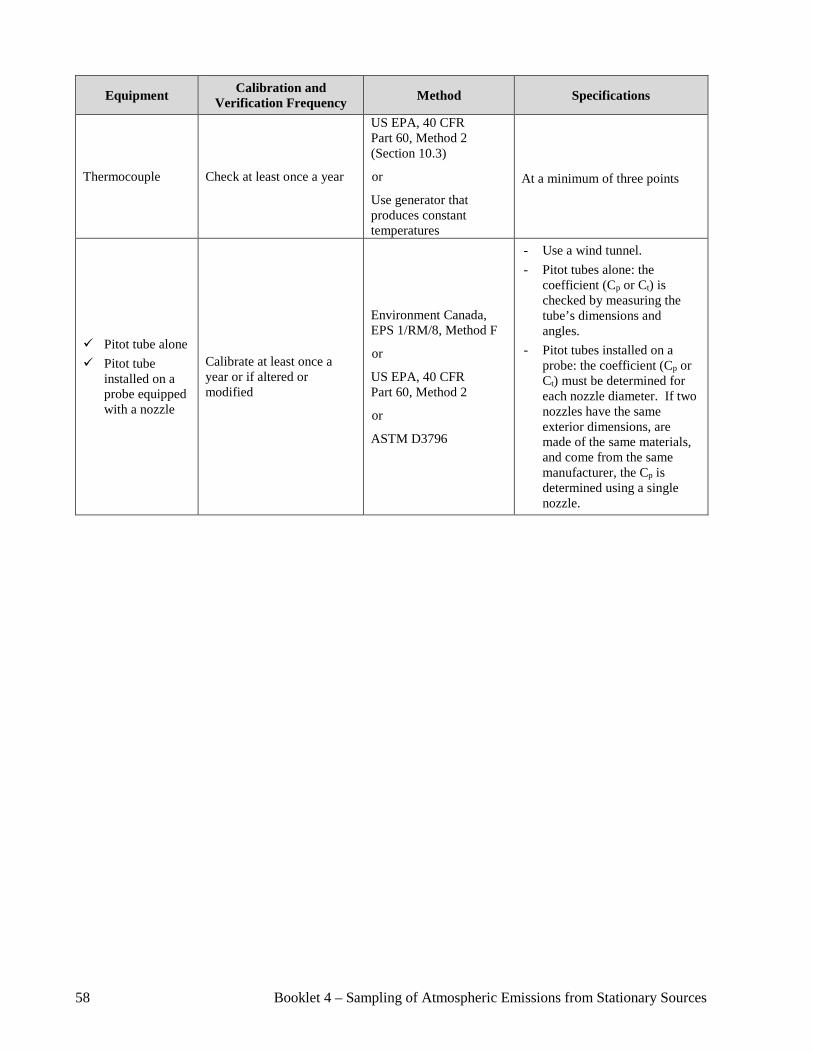
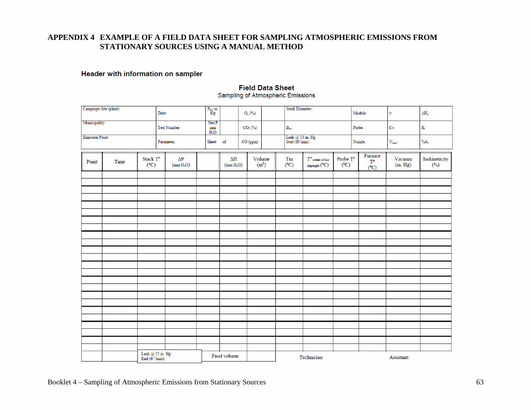
The handwritten field data sheets are filled out using indelible ink and are complete, accurate, and legible. Best practices requires that mistakes be crossed out, corrected, initialed and dated rather than erased. Appendix 5 shows an example of a field data sheet for manual sampling and an example of a recovery sheet can be found in Appendix 6. Forms are often specifically tailored to each sampling method to facilitate their use. A number of parameters are also recorded by data acquisition systems directly at the campaign site. This is the case for gas concentrations measured by gas analyzers. The required measures are taken to ensure that the recorded data is secure and cannot be altered. The files are recorded so they can be matched to the corresponding test. Spreadsheets are normally used to check field parameters and QCs such as those related to isokinetic conditions. As these calculation tools can be edited, they cannot be used as raw data. Various events can occur at the campaign site. According to best practices, any unauthorized deviation from a sampling method, for whatever reason, is recorded and clearly explained on the field data sheets or in the field notes. Possible effects on the results are documented. Any interruption, procedural problem, equipment breakdown, or part change on the sampling device is recorded and dated so it can be matched with the data at compilation. The various problems encountered will appear in the report (see Section 9) so that the results can be correctly interpreted. The chain of custody forms ensure sample integrity by preventing sample contamination and data switching, falsification, or loss. They make it possible to retrace the various steps the sample has gone through and to confirm that the analyzed sample corresponds to the sample that was collected. Each person who handles the samples completes this form to ensure that the chain of custody is properly documented and can be consulted at the data compilation step. Each person gets a copy. Appendix 7 shows an example of a general chain of custody form, which can be adapted to fit various sampling methods. 4.3 Data retention It is essential to keep relevant information on the sampling process for a sufficient period, especially when legal requirements are involved. It should be filed in such a way so that all the data on a project can be easily found. 5. CALIBRATION AND VERIFICATION Equipment used to measure raw field data consists mainly of dry gas meters, Pitot S tubes, manometers, thermocouples, temperature probes, and gas analyzers. They are kept in good working order, receive regular maintenance, and are calibrated at set intervals. The calibration procedures described in this section are those generally included in the methods recommended by Environment Canada, US EPA, and the ASTM.
8 Booklet 4 – Sampling of Atmospheric Emissions from Stationary Sources
Best practices require that all raw calibration data be recorded and kept. Valid calibration certificates should be available for consultation at all times. 5.1 Calibration and Verification of Sampling Equipment Table 3.1 in Appendix 3 presents calibration and verification methods and frequencies for the main sampling equipment. Items in the Specifications column must be taken into account. When a piece of equipment is modified or repaired, it must be checked and recalibrated and a new calibration certificate issued. The date of the most recent calibration is written on each piece of equipment, when possible. The handwritten raw data on which the certificate is based is kept as long as the certificate is valid and is available for consultation at all times, e.g., to check calculations for Pitot tube coefficients (Cp or Ct) and the dry gas meter correction factor (γ). 5.2 Calibration and Verification of Gas Analyzers Sampling methods for gas analyzers include calibration specifications, some of which are presented in Table 3.2 in Appendix 3. Calibration gases are certified to 2%. Calibration gases meeting the criteria in the US EPA protocol (EPA Traceability Protocol for Assay and Certification of Gaseous Calibration Standards) should be used whenever possible. The analysis certificates provided by the manufacturer for each gas cylinder are available on the campaign site and include an expiry date. A dilution system can be used to prepare calibration gas concentrations using more concentrated certified gases. It is designed to take parameters such as temperature, pressure, and the molecular weight of the gas mixture into account in calculating calibration and dilution gas flow rates in order to prepare a mixture containing the gas in question at a concentration as close as possible to that of the gas in the stack. This system is checked in the field before use and calibrated at least once a year using the procedures in US EPA Method 205. If the analyzer features more than one measurement scale, the scale closest to the target value should be chosen. Calibration errors are calculated by dividing the difference between readings by the highest gas concentration (span) rather than by the analyzer’s measurement scale. Below is a sample calculation of analyzer calibration error using Equation 7E-1 from US EPA Method 7E illustrating the difference.
Booklet 4 – Sampling of Atmospheric Emissions from Stationary Sources 9
Unlike other gas analyzers, a Fourier transform infrared spectrophotometer (FTIR) determines the concentration of substances or contaminants by comparing field-recorded spectra to reference spectra for various concentrations, such that the concentration of the substance or contaminant in question is within these increments. The reference spectra must be recorded directly on the analyzer in the lab by the manufacturer or at the campaign site. Reference spectra from commercial spectrum libraries cannot be used for quantitation. The data on which the reference spectra are based or the manufacturer’s certificates are kept and available for checks. Therefore, the FTIR does not have to be calibrated in the field. However, it must be field checked using specific calibration gases certified to 2% to ensure it is working properly. 6. PLANNING A SAMPLING CAMPAIGN It is essential to properly plan a sampling campaign, especially for initial sampling of emission points for which no preliminary data is available. The objective is to collect the required information in order to prevent errors and ensure that the sampling process and resulting data are of the highest quality. The planning process depends on the context and objective of the sampling campaign, whether for environmental compliance verification or knowledge acquisition.
𝐸𝐸 = |𝐶𝐶𝐶𝐶 − 𝐶𝐶𝐶𝐶|
𝐶𝐶𝐶𝐶 100
E : Calibration error equal to or smaller than 2% Cs : Highest concentration of the certified calibration gas (span) Cc : Concentration of the certified gas being checked Cd : Direct reading by analyzer
If the analyzer measurement scale used for the reading is 0 to 1,000 ppm, the span (Cs) is 150 ppm, the concentration of the certified gas (Cc) is 50 ppm, and the direct reading (Cd) for the gas is 55 ppm:
• The calculated error is: E = 55−50
150 100 = 3.3 %, which does not
meet the acceptability criteria (≤ 2 %). • If Cs is replaced by the measurement scale, E = 55−50
1000100 =
0.5 %, the acceptability criteria is met (≤ 2 %), but this calculation is not valid.
10 Booklet 4 – Sampling of Atmospheric Emissions from Stationary Sources
It takes into account the emission sources and emission points involved, the sampling sites, the parameters and substances or contaminants to be measured or sampled, as well as health and safety and QA/QC. Booklet 1, Section 2 of the Sampling Guide for Environmental Analysis also provides tips on planning sampling campaigns. 6.1 Planning by the Emission Source Operator The following subsections present the main planning aspects for which the emission source operator is responsible. 6.1.1 Context and objective of the sampling campaign
The context and objectives of a sampling campaign can vary and may or may not require exhaustive sampling. The main objectives of atmospheric emission sampling are as follows: Environmental compliance verification
These verifications may be held periodically at a frequency specified in the regulation or authorization.
Process or equipment performance assessments and verifications
This requires simultaneous sampling of the substances or contaminants in question upstream and downstream of the process or equipment.
Process and equipment performance verifications may be required by law or following commissioning or modification.
Atmospheric emission monitoring
Monitoring is spread out over time and may be required by an authorization or following an environmental intervention.
6.1.2 Parameters and substances or contaminants to be sampled
The source operator determines the parameters and substances or contaminants to be measured or sampled in accordance with the sampling campaign objective. The sampler may specify other parameters required for calculating emission rates, depending on the sampling method.
Booklet 4 – Sampling of Atmospheric Emissions from Stationary Sources 11
6.1.3 Description of the emission source The description of the source specifies its operating conditions. Among other things, it provides useful information for verifying compliance with a legal requirement (for example, the emission rate in kg/ton of product and the emission rate related to the process feed rate). If the emission source is a process, all activities generating or related to the emissions are described (e.g., loading, refining, and casting in a remelting furnace). The following aspects are described depending on the objective of the sampling campaign: Type of emission source (activity, equipment, process) and year of construction
or commissioning Rated power or rated heat capacity of the combustion device or industrial furnace Total number of production lines and number of lines that usually operate
simultaneously Process operation mode (continuous, cyclic, etc.) How long the source is in operation per day, week, and month Duration of and steps in a full cycle (preheating, loading, unloading, wait time,
etc.) Input type, feed rate, and composition Fuel type, feed rate, and composition Production type and rate Emission scrubbing or treatment equipment Diagram showing emission source in relation to other activities, equipment,
processes, or dividers Any other pertinent information
Much of this information can be found in supporting documents the operator submits with its applications for authorization under the Environment Quality Act (EQA).
6.1.4 Identification and description of emission points
The source operator is also responsible for identifying and describing the emission points. All the emission points associated with the emission source targeted by the sampling campaign (activity, equipment, or process) are considered, including the following: Type of emission point (stack, fan, vent, roof vent) Dimensions (length, width, diameter) Height in relation to the ground and roof
12 Booklet 4 – Sampling of Atmospheric Emissions from Stationary Sources
Existing sampling sites (location of sampling ports, dimensions, position in relation to flow disturbances, etc.)
Type of CEMS, if any (e.g., for carbon monoxide, nitrogen oxides, or sulfur dioxide)
Available services (platform, shelter, electricity, etc.)
It is a good idea to locate each selected emission point on a diagram and associate it with the source (activity, equipment, process). The sampler should be provided with a diagram, sketch, or photo of each previously sampled emission point specifying the various heights, areas, and existing sampling sites, when available. If the characteristics of the gases emitted at the emission points targeted by the sampling campaign are known, they should be indicated: Composition Temperature Flow rate and velocity Moisture content Type of substances or contaminants emitted and their estimated concentration or
emission rates This preliminary data is used to calculate the parameters for pump adjustments during sampling and the nozzle size needed to ensure sampling under isokinetic conditions, as required by certain sampling methods.
6.1.5 Identification of scrubbing equipment Each piece of scrubbing equipment related to the emission source is identified. This equipment can be included on the diagram showing the emission source and emission points. The following information should be provided: Type of equipment (cyclone, dust remover, wet or dry scrubber, electrostatic
precipitator, etc.) Estimated concentration of the substance or contaminant to be verified if the
objective of the sampling campaign is to verify scrubbing performance or the equipment’s destruction and removal efficiency (DRE)
Any other useful information 6.1.6 Health and safety rules on the campaign site
The emission source operator must ensure that the sampler is aware of existing health and safety rules on the campaign site and follows them during the sampling work.
Booklet 4 – Sampling of Atmospheric Emissions from Stationary Sources 13
6.2 Planning of Sampling Campaign Execution Planning of sampling campaign execution is based on previously gathered information. A preliminary visit to the campaign site may be required, particularly if the emission points have never been sampled before. 6.2.1 Choice of sampling methods
The sampling method is chosen based on the objective of the sampling campaign, the type of emission source, and the emission points to be sampled (see tables in Appendix 1 and Section 2). Certain emission points may have particular characteristics that prevent the use of reference methods (e.g., impossibility of properly installing the sampling equipment, temperature that is too high, or a gas stream velocity that is too low). The operator must first consider temporarily adjusting the emission point (e.g., lengthening an output duct on the roof) so the reference method can be used. If this is not possible, changes in the method may be necessary. In such cases, approval from the Ministry or the authority concerned is required prior to sampling.
6.2.2 Preliminary visit to the campaign site
The preliminary visit is used to gather information to ensure optimal planning of the sampling campaign. Diagrams provided by the operator can be clarified or sketches made of the emission points (see Section 6.1.4). It also serves to confirm and clarify information on the emission source, emission points, required equipment, and related services (safe platform, heated shelter, sampling ports, means of communication, work area for handling samples, etc.). Constraints related to each sampling site can be identified, including site access, configuration of the emission point, or characteristics of the gases. An emission point should not be excluded from the sampling campaign because of a problem with access to the sampling site. In the event of major difficulties, the Ministry or the authority concerned must be consulted. The preliminary visit is also used to establish the approximate characteristics of the gases (see Section 6.1.4), particularly when the source is first sampled, and to identify problems associated with their flow (stability, flow rate, cyclonic or reverse flow). Some preliminary measurements are generally made for this purpose. The choice of sampling method may be changed following the preliminary visit based on what is observed.
14 Booklet 4 – Sampling of Atmospheric Emissions from Stationary Sources
6.2.3 Sampling materials
Once the sampling method is selected, a list of sampling materials (equipment, reagents, glassware, containers, etc.) can be drawn up. This ensures that all the required materials are available and in good working condition. A sufficient number of replacement parts should also be provided for. It is important to properly plan for sampling material preparation to allow time for preliminary steps such as calibrating equipment (see Section 5), weighing filters, and preparing or decontaminating containers and intermediary environments (e.g., adsorbents).
6.2.4 Sampling team
The sampling team is big enough and made up of members qualified to conduct high quality tests at each emission point. To carry out the tests using a manual sampling method (see Section 2), at least two people are required at the emission point. When the method requires isokinetic conditions, the team concentrates its efforts on monitoring these conditions. If two or more isokinetic tests are performed simultaneously at the same emission point, one team member is designated to ensure that the isokinetic conditions are maintained at all times for each test. A scientific authority or team leader is part of each sampling team. The scientific authority or team leader is a professional or technician with the training and experience described in Lignes directrices concernant les prélèvements des émissions atmosphériques en provenance de sources fixes, DR-12-AIR-01, which is available on the CEAEQ website. The team members’ tasks are clearly defined to ensure that sampling is carried out properly.
6.2.5 Representative operating conditions of the source The tests are conducted under the source’s representative (normal) operating conditions. These include conditions specific to the source itself (inputs, fuel, cycle length, etc.) and to the scrubbing system, if applicable.
In sampling campaigns designed to verify destruction and removal efficiency (DRE), the quantity of gas fed and the volume of gas withdrawn must be sufficient for this purpose. A theoretical verification of the feed quantity is done prior to the test, using the substance’s detection limit in stack samples and the gas flow in the stack.
If the sampling campaign is designed to verify compliance with an emission rate (e.g., kg of total particles/ton of finished product) or a concentration (mg/m3 R), the tests are conducted under standard operating conditions:
Booklet 4 – Sampling of Atmospheric Emissions from Stationary Sources 15
For combustion equipment, at not less than 75% of the rated heat capacity or rated power, as applicable
For other equipment and processes, at a production rate of at least 80% of the
capacity for which the authorization was issued under the Environment Quality Act (EQA) or of the source’s maximum capacity
If these operating conditions cannot be achieved (e.g., due to a decrease in the production rate of a piece of equipment or process), the Ministry or the authority concerned should be consulted regarding the source operating conditions that will be used during the sampling campaign.
It is up to the source operator to inform the sampler of the representative operating conditions that must be respected when conducting the tests. It is also recommended that the source operator assign at least one person to check and record the operating conditions during the sampling tests.
6.2.6 Data recording The field data and chain of custody forms (see Section 4.1) are drawn up and checked during the planning stages of the sampling campaign. Data acquisition systems are also checked to ensure that they meet the needs of the sampling campaign.
6.2.7 Test laboratories
Planning of the sampling campaign includes selecting the analysis lab. The choice is based on the substances or contaminants to be analyzed. When required by a regulation or authorization, it takes into account that the analyses must be conducted by a laboratory accredited under the EQA or, in the absence of a certified lab for the substance or contaminant in question, a lab that meets the ISO/CEI 17025 standard. For more information on the accreditation of test laboratories, see the document Programme d’accréditation des laboratoires d’analyse DR-12-PALA on the CEAEQ website. The website also contains a list of accredited laboratories and a list of accreditation domains.
6.2.8 Sampling schedule The sampling schedule is based on the minimum time prescribed by the sampling method to carry out each test and the availability of the sampling team and required equipment. In the case of a sampling campaign for an environmental compliance verification, the schedule also takes into account the fact that the emission source must be operating under representative conditions (see Section 6.2.5).
16 Booklet 4 – Sampling of Atmospheric Emissions from Stationary Sources
6.3 Quality Assurance and Control A QA/QC program is set up during the planning stage. It indicates not only the various sampling CQs, but also the human and material resources that will be used. Section 3 presents the main aspects to consider. 6.4 Health and Safety Members of the sampling team are responsible for their own safety. They must wear the required safety equipment and comply with applicable safety rules for the campaign site at all times (see Section 6.1.6). When required, they must have the necessary training for working at heights, operating a boom lift, or transporting hazardous materials. Their individual protection equipment must comply with the standards in effect. Section 6 in Booklet 1 of the Sampling Guide for Environmental Analysis contains the main health and safety aspects that must be adhered to during a sampling campaign. At the campaign site, team members must be able to communicate effectively with one another and with the representative designated by the source operator. 6.5 Sampling Specifications Before starting a sampling campaign, sampling specifications should be drawn up to make sure that all aspects have been covered and clearly understood by those involved in the project. Generally speaking, the specifications contain all necessary information for understanding the sampling campaign’s objective and implementation. The sampling specifications include the following items: 6.5.1 Source operator and campaign site
Indicate the operator’s name and contact information and the address of the campaign site. Providing a diagram or a map indicating their locations is a good idea.
6.5.2 Introduction
The introduction should include a brief description of the objective (see Section 6.1.1) and context of the sampling campaign.
This is necessary for sampling campaigns conducted as part of an environmental compliance verification.
In the case of a study or research project, it is important to clearly explain the objective.
Booklet 4 – Sampling of Atmospheric Emissions from Stationary Sources 17
6.5.3 Emission sources and their operating conditions
Identify, describe, and define the representative operating conditions at the emission sources targeted by the sampling campaign (see Sections 6.1.3 and 6.2.5).
Some aspects of the source’s operating conditions may be confidential. If so, it is up to the source operator to determine how they will be incorporated into or attached to the sampling specifications.
6.5.4 Emission points
Identify and describe each emission point (see Section 6.1.4). A site plan can make it easier to identify, locate, and allocate the emission points at an emission source.
The description gives the location and particular features of each emission point. Sketches or photos can be provided for illustration purposes.
6.5.5 Scrubbing system
Describe the scrubbing system, if any (see Section 6.1.5). 6.5.6 Parameters, substances/contaminants, and sampling methods
For each emission point, provide the parameters and substances or contaminants that will be measured or sampled as well as the selected sampling methods (see Sections 6.1.2 and 6.2.1).
Explain any constraints regarding the use of the sampling method (see Sections 6.2.1 and 6.2.2) and specify the means that will be used to deal with them.
6.5.7 Characteristics of gases
Indicate the approximate characteristics of the gases (see Sections 6.1.4 and 6.2.2) for each emission point, when available, as well as any problems associated with their flow (stability, flow rate, cyclonic or reverse flow).
6.5.8 Sampling site and traverse or sampling points
Give the location of the sampling site and the number of traverse or sampling points for each emission point as per the methods in Appendix 1, Table 1.1.
The sampling site may already exist if an emission point has been sampled previously (see Section 6.1.4).
6.5.9 Sampling equipment
Indicate the main sampling equipment that will be used for each sampling method.
18 Booklet 4 – Sampling of Atmospheric Emissions from Stationary Sources
6.5.10 Services at the campaign site
Indicate required services (electricity, shelter, appropriate work area for handling samples, etc.) at the campaign site.
6.5.11 Quality assurance and control activities
Indicate the QC methods used to ensure compliance with critical aspects of the sampling campaign and the main QA/QC activities for validating the results (see Section 3).
6.5.12 Sampling schedule
Provide a timeline for the sampling campaign (see Section 6.2.8). 6.5.13 Content of the sampling report
List the main items that will be included in the sampling report (see Section 9). 6.5.14 Sampling team
Indicate the planned makeup of the sampling team (see Section 6.2.4). The person in charge at the emission source is part of the team.
6.5.15 Other information
Add any other important information, including potential problems at given sampling sites.
7. SAMPLING Information gathered during the planning stage serves to guide the sampling work (see Section 6). It is included in the final specifications approved by each party. The date on which the sampling will start is set jointly by the sampler and the source operator based on the schedule drawn up during the planning stage (see Section 6.2.8). Unless otherwise indicated in a regulation or authorization, the number of tests to be conducted during the sampling campaign is always at least three per parameter, substance, or contaminant for each of the source’s representative operating conditions. If more than three tests are conducted, they are all presented in the sampling report (see Section 9). Tests that are interrupted or not completed do not have to be presented in the report. The decision to interrupt or reject a test is made in the field by the sampler when an unexpected event likely to invalidate the results occurs during sampling. This could involve an equipment breakdown, clogging of the sampling device, an inability to maintain isokinetic conditions, or leak test failure at the end of the sampling test.
Booklet 4 – Sampling of Atmospheric Emissions from Stationary Sources 19
A test cannot be subsequently rejected because of a higher result compared to other tests. However, if the result is caused by an unexpected event, the cause should be mentioned in the report. 7.1 Preparations for Sampling The scientific authority or team leader ensure that the designated sampling team is big enough and qualified to conduct high quality tests at each emission point. To carry out the tests using a manual sampling method (see Section 6.2.4), at least two people are required at the emission point. This ensures that someone is present at all times to take readings and handle any problems that may arise. It is a good idea to hold a preliminary meeting for the whole sampling team. The meeting serves to answer questions and to make sure everyone has the information they need to conduct the sampling, especially concerning any special requirements such as the use of a particular piece of equipment. Team members make sure they have all the required documents and material to conduct the sampling campaign. 7.1.1 Documents
The following documents, among others, are assembled and checked:
Operator’s contact information and location of the campaign site Final version of the sampling specifications, if any A copy of each sampling method to be used (see Section 6.2.1) Sampling and post-test components of the QA/QC program (see Sections 3.2 and
3.3) Necessary competency cards for the sampling work (e.g., for working at heights,
driving machinery such as boom lifts) Field data sheets and required forms for sampling and sample recovery
(see Section 4.1); Calibration certificates for the sampling equipment Calibration gas analysis certificates Shipping documents for transporting hazardous materials, as needed List of contact people and phone numbers, as needed
These documents should be available to team members at all times.
7.1.2 Required material
Checklists for each substance or contaminant and each sampling method are handy tools for ensuring that all the necessary material (equipment, reagents, glassware, containers, etc.) is ready and loaded into the mobile units (see Section 6.2.3).
20 Booklet 4 – Sampling of Atmospheric Emissions from Stationary Sources
The following checks and tasks should be completed before leaving for the campaign site:
Make sure the sampling equipment is in good working order and has been
calibrated (see Section 5) and that the calibration certificates are still valid. Collect sampling device glassware and decontaminate the sample containers
according to the procedures described in the sampling methods, if applicable. Make glassware cleaning blanks and keep them for subsequent analysis, if
applicable. Weigh and number the filters and record their weight in a logbook. Prepare solutions and reagents.
Solutions and reagents become an integral part of the sample, so they are prepared by qualified personnel according to the recommendations in the sampling methods. The quantities and volumes of the stock solutions used are recorded on the work forms and kept in a logbook. Labels on reagent vials indicate the date they were prepared, the person who prepared them, and the batch number of the original container of stock solution. Some sampling methods require freshly prepared solutions, which are made up in the field.
Make sure that all reagents, such as resin traps, are available. Make sure that all required safety equipment for team members is available and
in good condition.
Once these checks have been completed, the documents and material are carefully loaded into the mobile units to ensure safe transport for both equipment and personnel.
7.2 Sample Collection Upon arrival at the campaign site, the leader of the sampling team contacts the person in charge at the emission source. They discuss the various aspects of the sampling campaign, including the sampling schedule (see Section 6.2.8) and the representative operating conditions that will prevail at the emission source during the sampling. Unless otherwise indicated, the scrubbing system must be in operation and functioning optimally. The team members read the health and safety requirements and guidelines for the campaign site (see Section 6.4). The mobile unit should be parked as close as possible to the emission points. Members of the sampling team start setting up the equipment on the sampling sites. Before the tests begin, the team performs the checks required by the sampling methods and makes sure that the equipment is in good working order, including the dry gas meter using the critical orifice.
Booklet 4 – Sampling of Atmospheric Emissions from Stationary Sources 21
When everything is ready, the sampling team leader notifies the person in charge at the emission source that the tests are about to start. They can only begin if the emission source’s representative operating conditions are achieved (see Section 6.2.5). The team leader keeps in constant communication (e.g., by radio) with the designated person in charge at the emission source. If a piece of equipment breaks down, the production line stops, or any other incident occurs, the sampling team is immediately notified and sampling is stopped. Sampling can start up again when the source’s representative operating conditions have been re-established on the condition that this is achieved within a reasonable time period (no longer than one day) based on the substance or contaminant being sampled. During sampling, the procedures in the sampling methods are followed and the appropriate documentation (see Section 4.1) completed. The data to be collected on the sampling site is generally given in table form in the sampling methods since it is needed to calculate emissions or conduct the CQs. Below are some examples of data that are collected, generally for each sampling point, if applicable:
Temperature of the gases in the stack Differential pressure of the gases in the stack (∆P) Drop in pressure at the orifice meter (∆H) Volume indicated on the gas meter Temperature of the filter compartment (and cyclone) Temperature of the probe Temperature of the gases exiting the last impinger Temperature of the gas meter Vacuum pressure in the sampling device
If an instrument-based method is used, the measurements are recorded directly at the campaign site. The sampler ensures that the files are properly identified for each test. The person in charge at the emission source monitors and records the operating parameters required for the sampling campaign’s objective (e.g., feed rate of inputs and fuel, production rate). The person in charge at the emission source is notified when the tests are completed and the sampling team starts dismantling the equipment. In the case of manual sampling, the sampling device is detached from its rail, the probe is removed, and all the orifices are sealed with a material appropriate to the type of substance or contaminant sampled (e.g., aluminum paper or Teflon tape). The sampling device is then carefully transferred to the mobile unit or to another location that is clean and free of contamination for sample recovery.
22 Booklet 4 – Sampling of Atmospheric Emissions from Stationary Sources
7.3 Sample Recovery For manual methods, the recovery area must be clean and the counters clear and covered (e.g. with white paper) to avoid contamination before the sampling device is dismantled and the samples recovered. The following items are on hand, as needed:
Sample recovery procedure according to the sampling method Appropriate decontaminated glass or plastic containers such as vials, bottles, or
Petri dishes Plastic or Teflon probe brushes Plastic or Teflon wash bottles Tweezers for handling filters Appropriate gloves for recovering samples Impinger supports Electronic balance Reagents and chemicals of an appropriate grade for recovering samples Self-adhesive labels with all pertinent information such as the campaign site,
municipality, emission point, sample type, and sample code; samples can be labelled with a pencil as long as the information cannot be erased
Sample recovery forms Chain of custody forms Analysis request forms
When all necessary items for the recovery of the samples are on hand, any visible dirt on the probe and the impingers is cleaned and the sampling device dismantled. The impingers are placed directly on their supports and the other pieces of glassware are placed carefully on the counter. The following tasks are then carried out:
Recover the samples, meticulously following the instructions in the sampling method.
Transfer the samples to appropriate containers, which are then hermetically sealed.
Identify each bottle or vial containing a sample with a unique code, for example using a correctly completed, self-adhesive label, to avoid any chance of mixing up the samples.
Mark fluid levels in the bottles to check whether any of the sample fluid has been lost during transport to the laboratory.
Complete the chain of custody form onsite, one of the objectives being to make sure that the collected sample is the sample that will be analyzed.
Complete the analysis requests (onsite or at the sampler’s premises). The codes written on the analysis requests must be the same as those on the vials or bottles.
Booklet 4 – Sampling of Atmospheric Emissions from Stationary Sources 23
Store the samples in a secure location at an appropriate storage temperature, generally 4°C.
Additional information on sample registration can be found in Section 3.4 of Booklet 1 of the Sampling Guide for Environmental Analysis. 8. POST-TEST PROCEDURES The recovered samples are transported from the campaign site to the sampler's premises or shipped to the test laboratories in a secure, closed container, stored at an appropriate temperature. Required forms, including the chain of custody form, are completed by all persons involved. As soon as the samples arrive at the test laboratory or the sampler's premises, they are checked against the accompanying documents, such as analysis requests and chain of custody forms. Samples that require analysis at an external laboratory are selected, coded as per the chain of custody (see Section 4.1), and shipped safely. When required by a regulation or authorization, the samples must be analyzed by a laboratory accredited under the EQA or, where there is no laboratory accredited for the substance or contaminant, by a laboratory that meets the ISO/IEC 17025 standard. In all other cases (e.g., samples not required by a regulation or authorization), the analyses are performed as per available methods, in particular those of recognized organizations such as CEAEQ, Environment Canada, ASTM, NCASI, and US EPA. For more information on accreditation of test laboratories, please see the document Programme d’accréditation des laboratoires d’analyse DR-12-PALA, available on the CEAEQ website. The website also features a list of accredited laboratories and a list of accreditation domains. The raw field data and the results from the test laboratory are compiled, checked, approved, and then used to calculate emissions for the final report. 9. SAMPLING REPORT Once the sampling campaign is completed, a sampling report is drawn up. A number of items in the sampling report are described in the Planning a Sampling Campaign section (see Section 6) and covered, if applicable, in the sampling specifications (see Section 6.5). If sampling specifications are available, this is mentioned in the report. Aspects of the QA/QC program covered in Section 3.4 are considered in preparing the report. The report is based on the fieldwork performed and identifies any problems that may have affected the results. The person responsible for the report checks it in its entirety, dates, and signs it.
24 Booklet 4 – Sampling of Atmospheric Emissions from Stationary Sources
A regulation or authorization may require that the report be sent to the Ministry or the authority concerned. If so, it must contain the required information and be sent by the stated deadline. The sampling report contains the information below, although not necessarily in the order presented. Certain information in the report is related to equipment or process operating conditions and may be confidential. If so, it is up to the operator to determine how it will be incorporated into or attached to the report. 9.1 Summary The summary gives the reader an overview of the sampling campaign. It briefly presents the context and purpose of the campaign as well as the campaign site, the source and the emission points covered by the campaign. A table summarizing the results by test is provided, indicating dates and sampling periods. It presents the main conclusions and the main problems encountered, if any. 9.2 Introduction The introduction describes the context and objective of the sampling campaign (see Section 6.1.1) and presents the emission source, including source operating conditions and emission points, as well as the parameters, and substances or contaminants targeted by the sampling campaign. 9.3 Identification of the source operator and campaign site The sampling report provides the:
Source operator’s name and contact information (see Section 6.5.1) Location of the campaign site Name of the person in charge designated by the source operator and present during
the sampling campaign 9.4 Identification of the sampler, test laboratories, and subcontractors The sampling report also provides the:
Sampler’s name and contact information Names and duties of the members of the sampling team Names of the test labs used during the sampling campaign Names of any subcontractors and the list of services each one provided
Booklet 4 – Sampling of Atmospheric Emissions from Stationary Sources 25
9.5 Sampling The sampling report describes how the sampling campaign was carried out and provides the following information:
Description of the emission source sampled, including the operating conditions during sampling (see Sections 6.1.3 and 6.2.5) All source operating conditions related to the objective of the sampling campaign and in effect during each test are provided. The composition of inputs or fuels is provided when required for the purposes of the sampling campaign (e.g., checking DRE). Any anomalies related to source operating conditions are mentioned, along with whether they caused the sampling to be interrupted or the test to be rejected.
Name and description of the emission points sampled (see Section 6.1.4)
Description of the sampling sites (duct diameter, position in relation to flow disturbances, number of sampling points, location of sampling ports, etc.)
Type of scrubbing system, if any (see Section 6.1.5) Any anomalies related to scrubbing system operation are mentioned, along with whether they caused the sampling to be interrupted or the test to be rejected.
Parameters and substances or contaminants sampled (see Section 6.1.2)
Sampling methods used (see Sections 2 and 6.2.1) and any changes made (approvals obtained and deviations and their effects)
Sampling equipment used and their data calibration or verification data (see Section 5)
Sampling data, including test numbers, dates, and times
All the tests conducted during the sampling campaign are presented in the report and reasons given for any tests that were rejected. However, tests that were interrupted or never completed do not have to be discussed in the report (see Section 7).
Characteristics of the gases sampled for each test
These characteristics are presented in detail in a table.
Observations and comments on specific events that occurred during sampling, whether related to the emission source, the sampling methods or equipment, or characteristics of the sampling site or gases
Aspects of the QA\QC program applied during sampling (see Section 3.2)
26 Booklet 4 – Sampling of Atmospheric Emissions from Stationary Sources
9.6 Results All results and supporting data are provided in the sampling report. The results are calculated in accordance with the reference conditions specified in Québec legislation and expressed, for each test, in units appropriate for the sampling campaign objective (concentrations, emission rates, destruction and removal efficiency, etc.). Sample blank values are not subtracted from the results, unless the sampling method requires it. Results under the detection limit of the analysis methods are included in the calculations, depending on the situation and the substances or contaminants sampled (e.g., PAH, PCDD, or PCDF), the method used, and the objective of the sampling campaign. If a regulation or authorization requires calculations based on three tests, but more than three valid tests were performed, the highest values are used. Any calculation formulas not included or different from those in the sampling methods are provided in the sampling report. The results of the QCs are presented, especially those required by the sampling method for checking that isokinetic conditions were maintained throughout the tests. 9.7 Discussion and Conclusion The results are interpreted and discussed in relation to the sampling campaign objective. The discussion also covers the conduct of the entire sampling campaign (difficulty coordinating operating conditions with sampling, rejection of tests, etc.). Conclusions are drawn in relation to the objective of the sampling campaign and recommendations made, if applicable. 9.8 Appendices The following appendices should be included in the sampling report:
Field data sheets Calibration and verification data, including calibration certificates Analysis certificates, including for blanks, signed by a chemist Measurements for instrument-based methods Calculation sheets Photos of unusual situations or installations
Booklet 4 – Sampling of Atmospheric Emissions from Stationary Sources 27
10. OTHER METHODS The Micro-Ringelmann scale is used to measure the opacity of gray or black emissions in the atmosphere. It is a method of observation and comparison. Its specifications and the method for measuring opacity are described in the regulations that refer to it, namely the Clean Air Regulation and the Regulation Respecting Hot Mix Asphalt Plants. One of the methods for detecting leaks of volatile organic compounds (VOC) is US EPA Method 21 (US EPA, 40 CFR Part 60, Method 21). It can be used to locate and categorize concentrations of VOC leaks, but cannot be used alone to determine the mass emission rate of these compounds. 11. CONTINUOUS EMISSION MONITORING SYSTEMS (CEMS) INSTALLED
AT STATIONARY SOURCES The section on CEMSs installed at stationary sources is included in this booklet of the Sampling Guide for Environmental Analysis for information purposes only, since this type of system cannot currently be used to verify environmental compliance. A CEMS refers to a set of equipment and programs for continuously sampling, analyzing, and recording concentrations of one or more substances or contaminants in gaseous effluent released from a stationary source or the opacity of the effluent. Although a CEMS is similar to sampling equipment used for instrument-based methods, it is installed permanently at emission points (a stack, for example) of a stationary source. A CEMS is used to observe variations over time in the opacity of gaseous effluent or in the concentrations of substances or contaminants it contains. The resulting data can be used to adjust operating conditions at the emission source (e.g., a furnace or process). The parameters this equipment usually measures are oxygen (O2), carbon monoxide (CO), carbon dioxide (CO2), sulphur dioxide (SO2), nitrogen oxides (NOx), ammonia (NH3), hydrogen chloride (HCl), total reduced sulphur compounds (TRS), and particulates matter. Opacity can also be determined on a continuous basis. A CEMS is made up of a number of components, including a sampling interface, analyzer, and data acquisition and recording system. The sampling interface is installed directly at the sampling site and the data acquisition and recording system can either be at the emission point (e.g., the stack) or in a more accessible location such as cupboard on the floor. There are two main types of CEMS—extractive and in situ—based on the design of the sampling interface. In extractive systems, the gases are sampled at the emission point (e.g., a stack or duct) and piped to the analyzer. This type of system can be used for gases and particulates matter, but cannot determine opacity.
28 Booklet 4 – Sampling of Atmospheric Emissions from Stationary Sources
The following diagram shows an extractive CEMS.
Diagram 1 : Extractive CEMS
In an in situ system, the analyses are performed directly at the sampling point. This type of system can be used for gases such as O2, SO2 or NOx, particulates matter, and opacity. The analysis can be done at a specific location by a sensor on the tip of a probe (point analysis) or along a certain distance. In the latter case, light is transmitted through the emission point, and the interaction between the light and the gas is used to determine the concentration of the substance or contaminant. While in operation, a CEMS provides accurate, comprehensive data based on established performance specifications (design, installation, and operation) and the QA/QC program. The latest versions of the performance specifications and QA/QC procedures in the tables in Appendix 4 can be used to certify the CEMSs and ensure that they are in good working order. Some of the specifications and procedures may be considered inappropriate due to technological advances in CEMSs. Other procedures recommended by the CEMS manufacturer to ensure proper operation of the system can also be used.
Booklet 4 – Sampling of Atmospheric Emissions from Stationary Sources 29
12. BIBLIOGRAPHY
General References
ALBERTA ENVIRONMENTAL REGULATORY SERVICE, 1995. Alberta Stack Sampling Code, Alberta, Environmental Protection, Environmental Regulatory Service, 406 p.
CENTRE D’EXPERTISE EN ANALYSE ENVIRONNEMENTALE DU QUÉBEC, 2012. Programme d’accréditation des laboratoires d’analyse, DR-12-PALA, Centre d’expertise en analyse environnementale du Québec, current edition.
CENTRE D’EXPERTISE EN ANALYSE ENVIRONNEMENTALE DU QUÉBEC, 2015. Lignes directrices concernant les prélèvements des émissions atmosphériques en provenance de sources fixes, DR-12-AIR-01, Québec City, Ministère du Développement durable, de l’Environnement et de la Lutte contre les changements climatiques, 22 p.
CENTRE D’EXPERTISE EN ANALYSE ENVIRONNEMENTALE DU QUÉBEC, 2015. Programme d’accréditation d’échantillonnage environnemental, DR-12-PAÉE, Québec City, Ministère du Développement, de l’Environnement et de la Lutte contre les changements climatiques, 15 p.
CENTRE D’EXPERTISE EN ANALYSE ENVIRONNEMENTALE DU QUÉBEC, 2016. Programme d’accréditation des laboratoires d’analyse – Champs et domaines d’accréditation en vigueur, DR-12-CDA, Centre d’expertise en analyse environnementale du Québec City, current edition.
MINISTÈRE DU DÉVELOPPEMENT DURABLE, DE L’ENVIRONNEMENT ET DES PARCS DU QUÉBEC, 2008. Guide d’échantillonnage à des fins d’analyses environnementales : Cahier 1 – Généralités, Centre d’expertise en analyse environnementale du Québec, 58 p., 3 app.
MINISTRY OF WATER LAND AND AIR PROTECTION PROVINCE OF BRITISH COLUMBIA, 2003. British Colombia Field Sampling Manual.
ONTARIO MINISTRY OF ENVIRONMENT, 2010. Ontario Source Testing Code, Development Branch, Ontario Ministry of the Environment, 247 p.
UNITED STATES ENVIRONMENTAL PROTECTION AGENCY, 1994. Quality Assurance Handbook for Air Pollution Measurement Systems: Volume III, Stationary Source-Specific Methods, Report EPA 600/R-94/038c, 444 p.
UNITED STATES ENVIRONMENTAL PROTECTION AGENCY, 2012. Traceability Protocol for Assay and Certification of Gaseous Calibration Standards, (PDF), Publication No. EPA/600/R-12/53.
30 Booklet 4 – Sampling of Atmospheric Emissions from Stationary Sources
Methodological References
The most recent published edition of each method must be used.
Aluminium Association of Canada, Méthode de référence pour l’échantillonnage des particules et des fluorures totaux aux évents de toits des salles de cuves des alumineries au Québec
ALUMINIUM ASSOCIATION CANADA, 2015. Méthode de référence pour l’échantillonnage des particules et des fluorures totaux aux évents de toits des salles de cuves des alumineries au Québec, 31 p.
ASTM D3195
AMERICAN SOCIETY FOR TESTING AND MATERIALS, Revised 2015. D3195 – Standard Practice for Rotameter Calibration, ASTM International.
ASTM D3796
AMERICAN SOCIETY FOR TESTING AND MATERIALS, 2009. D3796 – Standard Practice for Calibration of Type S Pitot Tubes.
ASTM D6348
AMERICAN SOCIETY FOR TESTING AND MATERIALS, 2012. D6348 – Standard Test Method for Determination of Gaseous Compounds by Extractive Direct Interface Fourier Transform Infrared (FTIR) Spectroscopy.
Benzene, toluene, and xylene (BTX) determination
COMMUNAUTÉ URBAINE DE MONTRÉAL, 1990. Détermination du benzène, toluène et xylènes dans les sources fixes, Service de l’environnement, Division des laboratoires.
Gravimetric determination of particulates matter in gaseous effluent from stationary sources
VILLE DE MONTRÉAL, 2015. Méthode de référence : Détermination gravimétrique des particules dans des effluents gazeux provenant de sources fixes, Méthode de référence M-CR-5.4-042, 1.0.0, Division de l’expertise technique.
Environment Canada, EPS 1-AP-74-3
ENVIRONMENT CANADA, 1975. Standard Reference Methods for Source Testing: Measurement of Emissions of Sulphur Dioxide from Stationary Sources, EPS Report 1-AP-74-3, Government of Canada.
Booklet 4 – Sampling of Atmospheric Emissions from Stationary Sources 31
Environment Canada, EPS 1-AP-75-1
ENVIRONMENT CANADA, 1976. Standard reference methods for source testing: measurement of emissions of asbestos from asbestos mining and milling operations, EPS Report 1-AP-75-1, Government of Canada.
Environment Canada, EPS 1-AP-75-1A
ENVIRONMENT CANADA, 1978. Standard reference methods for source testing: measurement of emissions of asbestos from asbestos mining and milling operations, EPS Report 1-AP-75-1A, Government of Canada.
Environment Canada, EPS 1-AP-77-3
ENVIRONMENT CANADA, 1979. Standard Reference Methods for Source Testing: Measurement of Emissions of Nitrogen Oxides from Stationary Sources, EPS Report 1-AP-77-3, Government of Canada.
Environment Canada, EPS 1/PG/7
ENVIRONMENT CANADA, 2005. Protocols and performance specifications for continuous monitoring of gaseous emissions from thermal power generation, EPS Report 1/PG/7 (updated), Government of Canada.
Environment Canada, EPS 1/RM/1
ENVIRONMENT CANADA, 1989. Reference Method for Source Testing: Measurement of Releases of Gaseous Hydrogen Chloride from Stationary Sources, EPS Report 1/RM/1, Government of Canada.
Environment Canada, EPS 1/RM/2
ENVIRONMENT CANADA, 1989. Reference Method for Source Testing: Measurement of Releases of Selected Semi-volatile Organic Compounds from Stationary Sources, EPS Report 1/RM/2, Government of Canada.
Environment Canada, EPS 1/RM/5
ENVIRONMENT CANADA, 1990. Reference Method for Source Testing: Measurement of Releases of Mercury from Mercury Cell Chor-Alkali Plants, Reference Method EPS 1/RM/5, Government of Canada.
Environment Canada, EPS 1/RM/6
ENVIRONMENT CANADA, 1992. Reference method for source testing: measurement of releases of total reduced sulphur (TRS) compounds from pulp and paper operations, Reference Method EPS 1/RM/6, Government of Canada.
32 Booklet 4 – Sampling of Atmospheric Emissions from Stationary Sources
Environment Canada, EPS 1/RM/7
ENVIRONMENT CANADA, 1993. Reference method for source testing: measurement of releases of lead in particulate from stationary sources, Reference Method EPS 1/RM/7, Government of Canada.
Environment Canada, EPS 1/RM/8, Methods A to F
ENVIRONMENT CANADA, 1993. Reference Method for Source Testing: Measurement of Releases of Particulate from Stationary Sources, Reference Method EPS 1/RM/8, Government of Canada.
Method A – Determination of Sampling Site and Traverse Points
Method B – Determination of Stack Gas Velocity and Volumetric Flow Rate.
Method C – Determination of Molecular Weight by Gas Analysis.
Method D – Determination of Moisture Content.
Method E – Determination of Particulate Releases
Method F – Calibration Procedure for S-Type Pitot Tube, Dry Gas Meter and Orifice Meter
Environment Canada, EPS 1/RM/55, Methods H and I
ENVIRONMENT CANADA, 2013. Reference Method for Source Testing: Measurement of Releases of Fine Particulate Matter from Stationary Sources, Reference Method EPS 1/RM/55, 53 p.
Measuring the number of odour units (Dynamic olfactometry)
COMMUNAUTÉ URBAINE DE MONTRÉAL, 1990. Méthode de référence : Mesure du nombre d’unités d’odeur, Olfactomètre dynamique.
Cryogenic method
COMMUNAUTÉ URBAINE DE MONTRÉAL, 1998. Méthode de référence : Dosage des substances organiques dans les émissions de sources fixes, Méthode cryogénique.
NCASI, Determination of chlorine and chlorine dioxide in pulp bleach plant vents
NATIONAL COUNCIL OF THE PAPER INDUSTRY FOR AIR AND STREAM IMPROVEMENT, INC. (NCASI), 1997. Methods Manual – Determination of Chlorine and Chlorine Dioxide in Pulp Mill Bleach Plant Vents, Research Triangle Park, N.C.
Booklet 4 – Sampling of Atmospheric Emissions from Stationary Sources 33
NCASI, Method 98.01
NATIONAL COUNCIL FOR AIR AND STREAM IMPROVEMENT, INC. (NCASI), 1998. CI/WP-98.01, Methods Manual – Chilled Impinger Method For Use At Wood Products Mills to Measure Formaldehyde, Methanol and Phenol, Research Triangle Park, N.C.
NCASI, Method 99.02
NATIONAL COUNCIL FOR AIR AND STREAM IMPROVEMENT, INC. (NCASI), 2005. IM/CAN/WP-99.02, Methods Manual – Impinger/Canister Source Sampling Method for Selected HAPs at Wood Products Facilities, Research Triangle Park, N.C.
NF EN 13725 AFNOR, 2003. Qualité de l’air – Détermination de la concentration d’une odeur par olfactométrie dynamique, NF EN 13725, AFNOR Édition, 65 p.
US EPA, 40 CFR Part 51, Method 201A
UNITED STATES ENVIRONMENTAL PROTECTION AGENCY. Code of Federal Regulations, Title 40, Part 51 Appendix M, Method 201A – Determination of PM10 and PM2.5 Emissions from stationary sources, current edition.
US EPA, 40 CFR Part 51, Method 205
UNITED STATES ENVIRONMENTAL PROTECTION AGENCY. Code of Federal Regulations, Title 40, Part 51 Appendix M, Method 205 – Verification of gas dilution systems for field instrument calibrations, current edition.
US EPA, 40 CFR Part 60, Method 1
UNITED STATES ENVIRONMENTAL PROTECTION AGENCY. Code of Federal Regulations, Title 40, Part 60, Appendix A, Method 1 – Sample and Velocity Traverses for Stationary Sources, current edition.
US EPA, 40 CFR Part 60, Method 1A
UNITED STATES ENVIRONMENTAL PROTECTION AGENCY. Code of Federal Regulations, Title 40, Part 60, Appendix A, Method 1A – Sample and Velocity Traverses for Stationary Sources With Small Stacks or Ducts, current edition.
US EPA, 40 CFR Part 60, Method 2
UNITED STATES ENVIRONMENTAL PROTECTION AGENCY. Code of Federal Regulations, Title 40, Part 60, Appendix A, Method 2 – Determination of Stack Gas Velocity and Volumetric Flow Rate (Type S Pitot Tube), current edition.
34 Booklet 4 – Sampling of Atmospheric Emissions from Stationary Sources
US EPA, 40 CFR Part 60, Method 2C
UNITED STATES ENVIRONMENTAL PROTECTION AGENCY. Code of Federal Regulations, Title 40, Part 60, Appendix A, Method 2C – Determination of Gas Velocity and Volumetric Flow Rate in Small Stacks or Ducts (Standard Pitot Tube), current edition.
US EPA, 40 CFR Part 60, Method 3A
UNITED STATES ENVIRONMENTAL PROTECTION AGENCY. Code of Federal Regulations, Title 40, Part 60, Appendix A, Method 3A – Determination of oxygen and carbon dioxide concentrations in emissions from stationary sources (instrumental analyzer procedure), current edition.
US EPA, 40 CFR Part 60, Method 4
UNITED STATES ENVIRONMENTAL PROTECTION AGENCY. Code of Federal Regulations, Title 40, Part 60, Appendix A, Method 4 – Determination of moisture content in stack gases, current edition.
US EPA, 40 CFR Part 60, Method 5
UNITED STATES ENVIRONMENTAL PROTECTION AGENCY. Code of Federal Regulations, Title 40, Part 60, Appendix A, Method 5 – Determination of particulate matter emissions from stationary sources, current edition.
US EPA, 40 CFR Part 60, Method 5D
UNITED STATES ENVIRONMENTAL PROTECTION AGENCY. Code of Federal Regulations, Title 40, Part 60, Appendix A, Method 5D – Determination of particulate matter emissions from positive pressure fabric filters, current edition.
US EPA, 40 CFR Part 60, Method 5I
UNITED STATES ENVIRONMENTAL PROTECTION AGENCY. Code of Federal Regulations, Title 40, Part 60, Appendix A, Method 5I – Determination of low level particulate matter emissions from stationary sources, current edition.
US EPA, 40 CFR Part 60, Method 6
UNITED STATES ENVIRONMENTAL PROTECTION AGENCY. Code of Federal Regulations, Title 40, Part 60, Appendix A, Method 6 – Determination of sulfur dioxide emissions from stationary sources, current edition.
Booklet 4 – Sampling of Atmospheric Emissions from Stationary Sources 35
US EPA, 40 CFR Part 60, Method 6C
UNITED STATES ENVIRONMENTAL PROTECTION AGENCY. Code of Federal Regulations, Title 40, Part 60, Appendix A, Method 6C – Determination of sulfur dioxide emissions from stationary sources (instrumental analyzer procedure), current edition.
US EPA, 40 CFR Part 60, Method 7
UNITED STATES ENVIRONMENTAL PROTECTION AGENCY. Code of Federal Regulations, Title 40, Part 60, Appendix A, Method 7 – Determination of nitrogen oxide emissions from stationary sources, current edition.
US EPA, 40 CFR Part 60, Method 7E
UNITED STATES ENVIRONMENTAL PROTECTION AGENCY. Code of Federal Regulations, Title 40, Part 60, Appendix A, Method 7E – Determination of nitrogen oxides emissions from stationary sources (instrumental analyzer procedure), current edition.
US EPA, 40 CFR Part 60, Method 8
UNITED STATES ENVIRONMENTAL PROTECTION AGENCY. Code of Federal Regulations, Title 40, Part 60, Appendix A, Method 8 – Determination of sulfuric acid and sulfur dioxide emissions from stationary sources, current edition.
US EPA, 40 CFR Part 60, Method 10
UNITED STATES ENVIRONMENTAL PROTECTION AGENCY. Code of Federal Regulations, Title 40, Part 60, Appendix A, Method 10 – Determination of carbon monoxide emissions from stationary sources (instrumental analyzer procedure), current edition.
US EPA, 40 CFR Part 60, Method 13A
UNITED STATES ENVIRONMENTAL PROTECTION AGENCY. Code of Federal Regulations, Title 40, Part 60, Appendix A, Method 13A – Determination of total fluoride emissions from stationary sources (SPADNS Zirconium Lake method), current edition.
US EPA, 40 CFR Part 60, Method 13B
UNITED STATES ENVIRONMENTAL PROTECTION AGENCY. Code of Federal Regulations, Title 40, Part 60, Appendix A, Method 13B – Determination of total fluoride emissions from stationary sources (Specific ion electrode method), current edition.
US EPA, 40 CFR Part 60, Method 16C
UNITED STATES ENVIRONMENTAL PROTECTION AGENCY. Code of Federal Regulations, Title 40, Part 60, Appendix A, Method 16C – Determination of total reduced sulfur emissions from stationary sources, current edition.
36 Booklet 4 – Sampling of Atmospheric Emissions from Stationary Sources
US EPA, 40 CFR Part 60, Method 18
UNITED STATES ENVIRONMENTAL PROTECTION AGENCY. Code of Federal Regulations, Title 40, Part 60, Appendix A, Method 18 – Measurement of gaseous organic compound emissions by gas chromatography, current edition.
US EPA, 40 CFR Part 60, Method 21
UNITED STATES ENVIRONMENTAL PROTECTION AGENCY. Code of Federal Regulations, Title 40, Part 60, Appendix A, Method 21 – Determination of volatile organic compound leaks, current edition.
US EPA, 40 CFR Part 60, Method 25A
UNITED STATES ENVIRONMENTAL PROTECTION AGENCY. Code of Federal Regulations, Title 40, Part 60, Appendix A, Method 25A – Determination of total gaseous organic concentration using a flame ionization analyzer, current edition.
US EPA, 40 CFR Part 60, Method 26
UNITED STATES ENVIRONMENTAL PROTECTION AGENCY. Code of Federal Regulations, Title 40, Part 60, Appendix A, Method 26 – Determination of hydrogen halide and halogen emissions from stationary sources non-isokinetic method, current edition.
US EPA, 40 CFR Part 60, Method 26A
UNITED STATES ENVIRONMENTAL PROTECTION AGENCY. Code of Federal Regulations, Title 40, Part 60, Appendix A, Method 26A – Determination of hydrogen halide and halogen emissions from stationary sources isokinetic method, current edition.
US EPA, 40 CFR Part 60, Method 29
UNITED STATES ENVIRONMENTAL PROTECTION AGENCY. Code of Federal Regulations, Title 40, Part 60, Appendix A, Method 29 – Determination of metals emissions from stationary sources, current edition.
US EPA, 40 CFR Part 60, Procedure 1
UNITED STATES ENVIRONMENTAL PROTECTION AGENCY. Code of Federal Regulations, Title 40, Part 60, Appendix F, Procedure 1 – Quality assurance requirements for gas continuous emission monitoring systems used for compliance determination, current edition.
US EPA, 40 CFR Part 60, Procedure 2
UNITED STATES ENVIRONMENTAL PROTECTION AGENCY. Code of Federal Regulations, Title 40, Part 60, Appendix F, Procedure 2 – Quality assurance requirements for particulate matter continuous emission monitoring systems at stationary sources, current edition.
Booklet 4 – Sampling of Atmospheric Emissions from Stationary Sources 37
US EPA, 40 CFR Part 60, Procedure 3
UNITED STATES ENVIRONMENTAL PROTECTION AGENCY. Code of Federal Regulations, Title 40, Part 60, Appendix F, Procedure 3 – Quality assurance requirements for continuous opacity monitoring systems at stationary sources, current edition.
US EPA, 40 CFR Part 60, Procedure 6
UNITED STATES ENVIRONMENTAL PROTECTION AGENCY. Code of Federal Regulations, Title 40, Part 60, Appendix F, Procedure 6 – Quality assurance requirements for gaseous hydrogen chloride (HCl) continuous emission monitoring systems used for compliance determination at stationary sources, current edition.
US EPA, 40 CFR Part 60, PS-1
UNITED STATES ENVIRONMENTAL PROTECTION AGENCY. Code of Federal Regulations, Title 40, Part 60, Appendix B, Performance Specification 1 – Specifications and test procedures for continuous opacity monitoring systems in stationary sources, current edition.
US EPA, 40 CFR Part 60, PS-2
UNITED STATES ENVIRONMENTAL PROTECTION AGENCY. Code of Federal Regulations, Title 40, Part 60, Appendix B, Performance Specification 2 – Specifications and test procedures for SO2 and NOX continuous emission monitoring systems in stationary sources, current edition.
US EPA, 40 CFR Part 60, PS-3
UNITED STATES ENVIRONMENTAL PROTECTION AGENCY. Code of Federal Regulations, Title 40, Part 60, Appendix B, Performance Specification 3 – Specifications and test procedures for O2 and CO2 continuous emission monitoring systems in stationary sources, current edition.
US EPA, 40 CFR Part 60, PS-4
UNITED STATES ENVIRONMENTAL PROTECTION AGENCY. Code of Federal Regulations, Title 40, Part 60, Appendix B, Performance Specification 4 – Specifications and test procedures for carbon monoxide continuous emission monitoring systems in stationary sources, current edition.
US EPA, 40 CFR Part 60, PS-5
UNITED STATES ENVIRONMENTAL PROTECTION AGENCY. Code of Federal Regulations, Title 40, Part 60, Appendix B, Performance Specification 5 – Specifications and test procedures for TRS continuous emission monitoring systems in stationary sources, current edition.
38 Booklet 4 – Sampling of Atmospheric Emissions from Stationary Sources
US EPA, 40 CFR Part 60, PS-8A
UNITED STATES ENVIRONMENTAL PROTECTION AGENCY. Code of Federal Regulations, Title 40, Part 60, Appendix B, Performance Specification 8A – Specifications and test procedures for total hydrocarbon continuous monitoring systems in stationary sources, current edition.
US EPA, 40 CFR Part 60, PS-11
UNITED STATES ENVIRONMENTAL PROTECTION AGENCY. Code of Federal Regulations, Title 40, Part 60, Appendix B, Performance Specification 11 – Specifications and test procedures for particulate matter continuous emission monitoring systems in stationary sources, current edition.
US EPA, 40 CFR Part 60, PS-18
UNITED STATES ENVIRONMENTAL PROTECTION AGENCY. Code of Federal Regulations, Title 40, Part 60, Appendix B, Performance Specification 18 – Performance specifications and test procedures for gaseous hydrogen chloride (HCl) continuous emission monitoring systems at stationary sources, current edition.
US EPA, 40 CFR Part 61, Method 101A
UNITED STATES ENVIRONMENTAL PROTECTION AGENCY. Code of Federal Regulations, Title 40, Part 61, Appendix B, Method 101A – Determination of particulate and gaseous mercury emissions from sewage sludge incinerators, current edition.
US EPA, 40 CFR Part 61, Method 104
UNITED STATES ENVIRONMENTAL PROTECTION AGENCY. Code of Federal Regulations, Title 40, Part 61, Appendix B, Method 104 – Determination of beryllium emissions from stationary sources, current edition.
US EPA, 40 CFR Part 63, Method 306
UNITED STATES ENVIRONMENTAL PROTECTION AGENCY. Code of Federal Regulations, Title 40, Part 63, Appendix A, Method 306 – Determination of chromium emissions from decorative and hard chromium electroplating and chromium anodizing operations – Isokinetic method, current edition.
US EPA, 40 CFR Part 63, Method 320
UNITED STATES ENVIRONMENTAL PROTECTION AGENCY. Code of Federal Regulations, Title 40, Part 63, Appendix A, Method 320 – Measurement of vapor phase organic and inorganic emissions by extractive Fourier Transform Infrared (FTIR) Spectroscopy, current edition.
Booklet 4 – Sampling of Atmospheric Emissions from Stationary Sources 39
US EPA, 40 CFR Part 63, Method 323
UNITED STATES ENVIRONMENTAL PROTECTION AGENCY. Code of Federal Regulations, Title 40, Part 63, Appendix A, Method 323 – Measurement of formaldehyde emissions from natural gas-fired stationary sources – Acetyl acetone derivitization method, current edition.
US EPA, Method 0030
UNITED STATES ENVIRONMENTAL PROTECTION AGENCY. Test Methods for Evaluating Solid Wastes, Physical/Chemical Methods, SW-846, Method 0030 – Volatile organic sampling train, online.
US EPA, Method CTM 027
UNITED STATES ENVIRONMENTAL PROTECTION AGENCY. Conditional Test Methods, CTM-027 – Procedure for collection and analysis of ammonia in stationary sources, online.
US EPA, Method OTM 29
UNITED STATES ENVIRONMENTAL PROTECTION AGENCY. Other Test Method, OTM 29 – Sampling and analysis for hydrogen cyanide emissions from stationary sources, online.
US EPA, PPS-001
UNITED STATES ENVIRONMENTAL PROTECTION AGENCY. PPS-001: Preliminary performance specifications for ammonia continuous emission monitors (CEMs), current edition.
Booklet 4 – Sampling of Atmospheric Emissions from Stationary Sources 41
APPENDIX 1 REFERENCE METHODS FOR SAMPLING ATMOSPHERIC EMISSIONS FROM STATIONARY SOURCES
Table 1.1 – Reference Methods for Characterizing Gases ............................................................... 42
Table 1.5 – Accepted Combinations of Sampling Methods ............................................................ 49
Table 1.6 − Determination of Odour Concentrations ...................................................................... 50
Table 1.7 − Methods Applicable to Certain Parameters in Bylaw 2001-10 of the Communauté métropolitaine de Montréal1 .......................................................................................... 50
42 Booklet 4 – Sampling of Atmospheric Emissions from Stationary Sources
Table 1.1 – Reference Methods for Characterizing Gases
Parameter Method Additional Specifications and Requirements1
Determination of sampling site and traverse points
Environment Canada, EPS 1/RM/8-Method A
or US EPA, 40 CFR Part 60, Method 1
Modify emission point to make it compliant, as needed. The required number of points must be used. For example, if 24 points are required, each of the 24 points must be sampled with the probe.
US EPA, 40 CFR Part 60, Method 1A
Stack diameter from 10 cm (4 in.) to 30 cm (12 in.)
US EPA, 40 CFR Part 60, Method 5D
Applicable for positive pressure fabric filters
Determination of stack gas velocity and volumetric flow rate
Environment Canada, EPS 1/RM/8, Method B or US EPA, 40 CFR Part 60, Method 2
S-type Pitot tubes must be used if particulate matter is present.
US EPA, 40 CFR Part 60, Method 2C
Stack diameter from 10 cm (4 in.) to 30 cm (12 in.)
Determination of molecular weight by gas analysis
Environment Canada, EPS 1/RM/8, Method C None
Determination of moisture content
Environment Canada, EPS 1/RM/8, Method D or US EPA, 40 CFR Part 60, Method 4
Total filterable PM2.5 and condensable particulate matter
Environment Canada, EPS 1/RM/55, Method I
Condensable particulate matter
Environment Canada, EPS 1/RM/55, Method H
1. The additional specifications and requirements are applicable to each test. 2. An adaptation of this method, which avoids having to attach the entire sampling device to a rail, consists of inserting a
flexible line between the filter exit and the entrance of the first impinger. This way, inaccessible traverses can be sampled. This method can be used only for particulate sampling.
44 Booklet 4 – Sampling of Atmospheric Emissions from Stationary Sources
Table 1.3 – Reference Methods for Sampling Inorganic Substances or Contaminants
Substance or Contaminant Method Additional Specifications and Requirements1
Booklet 4 – Sampling of Atmospheric Emissions from Stationary Sources 45
Substance or Contaminant Method Additional Specifications and Requirements1
Inorganic acids other than chromic acid released by metallic surface treatment processes
US EPA, 40 CFR Part 60, Method 26, modified
Modifications:
• No filter
• Replace H2SO4 0,1N in first two impingers with distilled water.
Used if no droplets in the gases. Minimum collection time: 20 minutes
Minimum volume collected: 20 litres Analyze the anions corresponding to each acid in all impinger solutions (e.g., nitrates, phosphates, and sulfates).
US EPA, 40 CFR Part 60, Method 26A, modified
Modifications:
• No filter
• Replace H2SO4 0,1N in first two impingers with distilled water.
Used if there are droplets or a risk of droplets in the gases.
Minimum collection time: 60 minutes Minimum volume collected: 1.5 m3R Analyze the anions corresponding to each acid in all impinger solutions (e.g., nitrates, phosphates, and sulfates).
Sulphuric acid mist (H2SO4+SO2/SO3)
US EPA, 40 CFR Part 60, Method 8
Minimum collection time: 60 minutes
Minimum volume collected: 1.5 m3R Maximum collection rate: 28 L/minute
Chlorine and chlorine dioxide (Cl2 and ClO2)
NCASI, Determination of chlorine and chlorine dioxide in pulp bleach plant vents
Maximum collection time: 60 minutes Collection rate: 0.20 to 0.25 L/minute
Stop collecting when the solution in the second impinger turns yellow.
Used if there are droplets or a risk of droplets in the gases.
Minimum collection time: 60 minutes
Minimum volume collected: 1.5 m3R
Total reduced sulphur compounds (TRS) expressed as SO2
US EPA, 40 CFR Part 60, Method 16C*
Minimum collection time: 60 minutes Three calibration gases used at representative concentrations.
Total reduced sulphur compounds (H2S; CH3SH; (CH3)2S; (CH3)2S2)
Environment Canada, EPS 1/RM/6
Used when instrument-based method 16C does not apply or speciation of the compounds is required. Samples must be analyzed no more than one hour after they are collected.
46 Booklet 4 – Sampling of Atmospheric Emissions from Stationary Sources
Substance or Contaminant Method Additional Specifications and Requirements1
Hydrogen cyanide (HCN) US EPA, Method OTM-29
None
Carbon dioxide (CO2)
US EPA, 40 CFR Part 60, Method 3A*
Minimum collection time: 60 minutes
Three calibration gases used at representative concentrations.
CO2 calibration gas available on campaign site.
Each FTIR must be equipped with its own spectrum library saved on the instrument by the manufacturer or in the laboratory. Spectra from commercial libraries are not accepted.
US EPA, 40 CFR Part 63, Method 320*
or ASTM D6348*
Sulphur dioxide (SO2)
US EPA, 40 CFR Part 60, Method 6C*
Minimum collection time: 60 minutes
Three calibration gases used at representative concentrations.
SO2 calibration gas available on campaign site.
Each FTIR must be equipped with its own spectrum library saved on the instrument by the manufacturer or in the laboratory. Spectra from commercial libraries are not accepted.
US EPA, 40 CFR Part 63, Method 320*
or
ASTM D6348*
Environment Canada, EPS 1-AP-74-3 or US EPA, 40 CFR Part 60, Method 6
When the above instrument-based method is not possible.
Total fluorides (Ft) and particulate matter released at potroom roof vents in aluminum smelters
Aluminium Association of Canada, Méthode de référence pour l’échantillonnage des particules et des fluorures totaux aux évents de toits des salles de cuves des alumineries au Québec
Applicable only to potroom roof vents in aluminum smelters
Booklet 4 – Sampling of Atmospheric Emissions from Stationary Sources 47
Substance or Contaminant Method Additional Specifications and Requirements1
Carbon monoxide (CO)
US EPA, 40 CFR Part 60, Method 10*
Minimum collection time: 60 minutes Three calibration gases used at representative concentrations.
CO calibration gas available on the campaign site.
Each FTIR must be equipped with its own spectrum library saved on the instrument by the manufacturer or in the laboratory. Spectra from commercial libraries are not accepted.
US EPA, 40 CFR Part 63, Method 320*
or
ASTM D6348*
Nitrogen oxides (NOx)
US EPA, 40 CFR Part 60, Method 7E*
Minimum collection time: 60 minutes
Three calibration gases used at representative concentrations.
NO calibration gas available at campaign site. Each FTIR must be equipped with its own spectrum library saved on the instrument by the manufacturer or in the laboratory. Spectra from commercial libraries are not accepted.
US EPA, 40 CFR Part 63, Method 320*
or
ASTM D6348*
Environment Canada, EPS 1-AP-77-3
or US EPA, 40 CFR Part 60, Method 7
When the above instrument-based method is not possible.
Other method approved and published by a recognized body
For specific VOCs, choose an appropriate method based on the type of source, the VOCs in question, and their expected concentrations.
Requires approval from the Ministry.
Formaldehyde
NCASI, Method 98.01 or
US EPA, 40 CFR Part 63, Method 323
Minimum collection time: 60 minutes Maximum collection rate: 0.4 L/minute
Polycyclic aromatic hydrocarbons (PAH)
Method in Appendix 2 of this booklet
Minimum collection time: 120 minutes
Minimum volume collected: 2 m3R
Total hydrocarbons or total gaseous organic compounds (methane or non-methane – TGOC or NMOC)
US EPA, 40 CFR Part 60, Method 25A*
For organic compounds other than methane, a NMOC analyser is used.
Minimum collection time: 60 minutes
* Instrumental 1. The additional specifications and requirements are applicable to each test.
Booklet 4 – Sampling of Atmospheric Emissions from Stationary Sources 49
Table 1.5 – Accepted Combinations of Sampling Methods
Contaminant Method
Filterable PM10 and PM2.5 and condensable particulate matter
US EPA, 40 CFR Part 51, Method 201A and Environment Canada, EPS 1/RM/55, Method H
Particulate matter and metals Environment Canada, EPS 1/RM/8, Method E or US EPA, 40 CFR Part 60, Method 5 and US EPA, 40 CFR Part 60, Method 29
Particulate matter and Be Environment Canada, EPS 1/RM/8, Method E or US EPA, 40 CFR Part 60, Method 5 and US EPA, 40 CFR Part 60, Method 104
Particulate matter and Hg Environment Canada, EPS 1/RM/8, Method E or US EPA, 40 CFR Part 60, Method 5 and US EPA, 40 CFR Part 60, Method 101A
Particulate matter and SO2 Environment Canada, EPS 1/RM/8, Method E or US EPA, 40 CFR Part 60, Method 5 and Environment Canada, EPS 1-AP-74-3 or US EPA, 40 CFR Part 60, Method 6
Particulate matter and HCl Environment Canada, EPS 1/RM/8, Method E or US EPA, 40 CFR Part 60, Method 5 and Environment Canada, EPS 1/RM/1
Particulate matter and hydrogen halides and halogens
Environment Canada, EPS 1/RM/8, Method E or US EPA, 40 CFR Part 60, Method 5 and US EPA, 40 CFR Part 60, Method 26A
Particulate matter and PAH Environment Canada, EPS 1/RM/8, Method E or US EPA, 40 CFR Part 60, Method 5 and Appendix 2 of this booklet
50 Booklet 4 – Sampling of Atmospheric Emissions from Stationary Sources
Table 1.6 − Determination of Odour Concentrations
Contaminant Method Additional Specifications and Requirements
Odour NF EN 13725 None
Table 1.7 − Methods Applicable to Certain Parameters in Bylaw 2001-10 of the Communauté métropolitaine de Montréal 1
Parameter Method Additional Specifications and Requirements
Total particulate matter2 Environment Canada, EPS 1/RM/8, Method E and
Détermination gravimétrique des particules dans des effluents gazeux provenant de sources fixes
Détermination du benzène, toluène et xylènes dans les sources fixes (BTX)
Minimum collection time: 60 minutes Minimum volume collected: 12 litres Applicable to other VOCs depending on conditions.
Number of odour units Mesure du nombre d’unités d’odeur, Olfactomètre dynamique
None
1. Bylaw 2001-10 applies only to the Agglomération de Montréal. To obtain a copy of these methods or for any related questions, please contact Division du contrôle des rejets industriels of Service de l’environnement de la Ville de Montréal at 514 280-4330.
2. According to the definition in Bylaw 2001-10 of the Communauté métropolitaine de Montréal.
Booklet 4 – Sampling of Atmospheric Emissions from Stationary Sources 51
APPENDIX 2 SAMPLING POLYCYCLIC AROMATIC HYDROCARBONS (PAH) FROM STATIONARY SOURCES
1. INTRODUCTION Polycyclic aromatic hydrocarbons (PAH) are contaminants released into the atmosphere by certain industries and the burning of wood. Some of them, such as benzo(a)pyrene have very high toxicities and are carcinogenic. PAHs are made up of two or more benzene rings, with the two adjacent rings sharing at least two carbon atoms. A list of PAHs sampled using this method is presented in Table A. 2. PRINCIPLE This sampling method is used jointly with Environment Canada’s EPS 1/RM/8 method1. The samples are collected at the source under isokinetic conditions using the appropriate sampling device. The gases pass through a nozzle of known diameter, a heated probe, and a heated fiberglass filter, which traps particulate matter. They are then cooled to 20°C or below before passing through a trap filled with Tenax- or XAD-2-type resin, which adsorbs most of the PAHs. The gases then pass through the water-filled impingers to condense moisture, and finally through a silica gel where residual moisture is retained. The collected samples are analyzed at a laboratory accredited by the Ministry and the results are used to calculate PAH emissions released into the atmosphere. 3. EQUIPMENT AND REAGENTS The sampling device is assembled as described in Environment Canada’s Method EPS 1/RM/8 by inserting a condenser and resin trap between the filter and the first impinger (or optional condensate trap). These two components are cooled by ice water circulated by a submersible pump in the tank containing the impingers. Nitrile gloves must be worn while handling the filter and resin trap. The sampling device is made up of the following components:
Stainless steel or glass (preferred) nozzle of a precisely measured diameter
Stainless steel or glass (preferred) probe with a heating sleeve that can maintain a temperature of 120°C ± 14°C
Glass filter support in a casing heated to 120°C ± 14°C
1 Environment Canada, Reference Method for Source Testing: Measurement of Releases of Particulate from Stationary
Sources, Reference Method EPS 1/RM/8, Government of Canada, 1993.
52 Booklet 4 – Sampling of Atmospheric Emissions from Stationary Sources
Fiberglass filter precalcined in an oven at 400°C for 16 hours
Glass condenser cooled in water and capable of maintaining the temperature of the gas output at 20°C or lower
Glass resin trap filled with about 15 g of Tenax- or XAD-2- type resin. The Tenax®-GC or XAD-2 resin is first cleaned in a Soxhlet extractor for 16 hours using hexane, then dried in an oven for 16 hours or until a constant weight is achieved. At assembly, the resin container is covered with aluminum paper. The resin is cooled with water and its temperature maintained at 20°C or lower.
Condensate trap (optional)
Impinger 1 containing 100 mL of demineralized water Impinger 2 containing 100 mL of demineralized water Impinger 3 empty Impinger 4 containing 200 to 300 g of anhydrous silica gel
Remark: Do not use a lubricant to seal the various components of the sampling device. 4. SAMPLING PROCEDURE Before collecting the samples, make sure that the sampling site has been properly selected according to Environment Canada’s Method EPS 1/RM/8. The angles of the gas stream must be measured to ensure that the gas stream is neither cyclonic nor reversed. Then follow Method EPS 1/RM/8 to calculate the number of sampling points, molecular weight, and moisture content and to ensure the required isokinetic conditions. A bigger sample volume must be collected (minimum 2 m3) for at least two hours. During sampling, the vacuum in the sampling train is recorded for each point to make sure that isokinetic conditions are maintained. The temperature of the resin must be recorded for each sampling point and must not exceed 20°C. At the end of the tests, the sampling device is dismantled, all orifices are sealed with aluminum paper, and the device is carefully transported to a clean location free of contamination for sample recovery. 5. SAMPLE RECOVERY Nitrile gloves must be worn when recovering the filter and resin trap. The sampling device is recovered as follows: Nozzle and probe: Wash with HPLC acetone and brush. Pour the rinse liquid into a properly
identified amber glass bottle equipped with a Teflon cap.
Booklet 4 – Sampling of Atmospheric Emissions from Stationary Sources 53
Filter: Remove from the filter support with stainless steel tools and place in a glass Petri plate. Cover the Petri plate with aluminum paper and properly identify.
Glassware located after the filter: Rinse the glassware between the filter and the condenser with HPLC acetone and pour the rinse liquid into a properly identified amber glass bottle.
Condenser: Weigh the condenser and record its final mass. Rinse it with acetone and add the rinse liquid to the bottle containing rinse liquid from the glassware located after the filter.
Resin trap: Dismantle and weigh the trap and seal the orifices with Teflon tape. Cover the trap with aluminum paper and properly identify.
Condensate trap and impingers: Weigh the trap and impingers and record their mass. Empty them into a properly identified amber glass bottle.
Silica gel: Weigh the silica gel and record its mass. Keep in a container for subsequent regeneration.
Store the Petri plate and sample bottles in a refrigerated environment (around 4oC) until they can be analyzed. 6. QUALITY CONTROL Before sampling begins, the resin traps are filled in the lab, the orifices sealed with Teflon tape, and the traps stored in the dark. To prevent contamination, the resin must not be stored in a large bottle and then used to fill the resin traps in the field. If the resin is taken into the field, it must be stored in amber glass bottles containing only 20 to 30 g so that each bottle is used to fill only one resin trap. All glassware used in the sampling device must be cleaned with HPLC-grade acetone and dried in an oven. The Petri plate containing the filter must be made of glass and cleaned beforehand with HPLC acetone and dried in an oven. The amber glass bottles must be cleaned beforehand with HPLC acetone and equipped with Teflon caps. Resin, filter, acetone, and demineralized water blanks must be prepared. 7. SAMPLE ANALYSIS The samples are sent to a Ministry-accredited laboratory for analysis. The analysis certificates issued by the laboratory present the results by individual PAH.
54 Booklet 4 – Sampling of Atmospheric Emissions from Stationary Sources
The nozzle and probe rinse liquids, the filter, the resin, and the rinse liquids from the glassware located after the filter and the condenser are analyzed for PAHs. The content of the optional condensate trap and the impingers from a single test is analyzed for PAHs for quality control purposes. 8. CALCULATIONS The results of the lab analyses are used to calculate PAH concentrations in the gases or their rate of release into the atmosphere. They are calculated in accordance with the reference conditions (25°C and 101.3 kPa). PAH isomers can be summed, depending on the objective. 9. BIBLIOGRAPHY
1- CALIFORNIA ENVIRONMENTAL PROTECTION AGENCY, 1997. Method 429, Determination of Polycyclic Aromatic Hydrocarbon (PAH) Emissions from Stationary Sources, Air Resources Board.
2- ENVIRONMENT CANADA, 1989. Reference Method for Source Testing : Measurement of Releases of Selected Semi-volatile Organic Compounds from Stationary Sources, EPS Report 1/RM/2, Government of Canada.
3- UNITED STATES ENVIRONMENTAL PROTECTION AGENCY. Code of Federal Regulations, Title 40, Part 60, Appendix A, Method 23 – Determination of Polychlorinated Dibenzo-p-Dioxina and Polychlorinated Dibenzofurans from Stationary Sources, Current edition.
4- UNITED STATES ENVIRONMENTAL PROTECTION AGENCY. SW-846 Test Method 0010: Modified Method 5 Sampling Train, part of Test Methods for Evaluating Solid Waste, Physical/Chemical Methods (PDF).
Booklet 4 – Sampling of Atmospheric Emissions from Stationary Sources 55
Table A –PAHs Measured Using the Sampling Method
Compound Remarks 1,3-Dimethylnaphtalene 1-Chloronaphtalene 1-Methylnaphtalene 1-Nitropyrene 2,3,5-Trimethylnaphtalene 2-Chloronaphtalene 2-Methyl chrysene 2-Methyl fluoranthene 2-Methylnaphtalene 3-Methyl chrysene 3-Methylcholanthrene 4+5+6-Methyl chrysene Sum of three isomers 7,12-Dimethylbenzo(a)anthracene 7H-Dibenzo(c,g)carbazole Acenaphthene Acenaphthylene Anthanthrene Anthracene Benzo(a)anthracene Benzo(a)pyrene Benzo(b)+(j)fluoranthene Sum of two isomers Benzo(c)acridine Benzo(c)phenantrene Benzo(e)pyrene Benzo(g,h,i)perylene Benzo(k)fluoranthene Carbazole Chrysene Coronene Dibenzo(a,c)+(a,h)antracene Sum of two isomers Dibenzo(a,e)fluoranthene Dibenzo(a,e)pyrene Dibenzo(a,h)acridine Dibenzo(a,h)pyrene Dibenzo(a,i)pyrene Dibenzo(a,j)anthracene Dibenzo(a,l)pyrene Fluoranthene Fluorene Indeno(1,2,3-c,d)pyrene Naphthalene Perylene Phenanthrene Pyrene
56 Booklet 4 – Sampling of Atmospheric Emissions from Stationary Sources
APPENDIX 3 CALIBRATION AND VERIFICATION
Table 3.1 – Sampling Equipment Calibration and Verification ‒ Frequency and Methodology .... 57
Table 3.2 – Gas Analyzer Calibration and Verification ‒ Frequency and Methodology ................ 59
Booklet 4 – Sampling of Atmospheric Emissions from Stationary Sources 57
Table 3.1 – Sampling Equipment Calibration and Verification ‒ Frequency and Methodology
Equipment Calibration and Verification Frequency Method Specifications
Anemometer
Calibrate every two years except for permanently installed anemometers Calibrate at least once a year for permanently installed anemometers
Not applicable
Certification by manufacturer or Propeller anemometer: using a reference anemometer Sonic and optical anemometers: using a wind tunnel.
Barometer Check before each use US EPA, 40 CFR Part 60, Method 2 (Section 10.4)
None
Nozzle Check before each use US EPA, 40 CFR Part 60, Method 5 (Section 10.1)
Before each use, measure the diameter of the nozzle in the field with a certified micrometer. Remove any scratched, toothed, or corroded nozzles and repair before use.
Dry gas meter
Calibrate at least once a year
Environment Canada, EPS 1/RM/8, Method F
or
US EPA, 40 CFR Part 60, Method 5
Use one of the following: - Spirometer (primary
standard) - Wet gas meter calibrated
using a primary standard - Dry gas meter calibrated
using a spirometer never used in the field.
Check before each use Not applicable Use the critical orifice that gives the flow rate nearest to the expected sampling rate.
Temperature probe Calibrate at least once a year Not applicable Use a certified temperature
simulator.
Manometer Calibrate at least once a year
US EPA, 40 CFR Part 60, Method 2 (Section 6.2.1)
None
Critical orifice Ask the manufacturer for the calibration certificate.
Rotameter or flowmeter
Calibrate at least once a year
ASTM D3195 A primary standard can also be used.
Dilution system Calibrate at least once a year
US EPA, 40 CFR Part 51, Method 205 None
58 Booklet 4 – Sampling of Atmospheric Emissions from Stationary Sources
Equipment Calibration and Verification Frequency Method Specifications
Thermocouple Check at least once a year
US EPA, 40 CFR Part 60, Method 2 (Section 10.3)
or
Use generator that produces constant temperatures
At a minimum of three points
Pitot tube alone Pitot tube
installed on a probe equipped with a nozzle
Calibrate at least once a year or if altered or modified
Environment Canada, EPS 1/RM/8, Method F
or
US EPA, 40 CFR Part 60, Method 2
or
ASTM D3796
- Use a wind tunnel. - Pitot tubes alone: the
coefficient (Cp or Ct) is checked by measuring the tube’s dimensions and angles.
- Pitot tubes installed on a probe: the coefficient (Cp or Ct) must be determined for each nozzle diameter. If two nozzles have the same exterior dimensions, are made of the same materials, and come from the same manufacturer, the Cp is determined using a single nozzle.
Booklet 4 – Sampling of Atmospheric Emissions from Stationary Sources 59
Table 3.2 – Gas Analyzer Calibration and Verification ‒ Frequency and Methodology
Analyser Calibration and Verification Frequency Method Specifications
O2, CO, CO2, NOx and SO2
Calibrate before each use US EPA, 40 CFR Part 60, Method 7E
Calibration errors must be calculated by dividing the difference between readings by the highest gas concentration (span) rather than by the analyzer’s measurement scale. Except for O2, a FTIR can be used if the method criteria are met when checked with specific gases.
Total hydrocarbons Calibrate before each use US EPA, 40 CFR Part 60, Method 25A None
Check using standards specific to the substances or contaminants in question.
60 Booklet 4 – Sampling of Atmospheric Emissions from Stationary Sources
APPENDIX 4 EXAMPLES OF PERFORMANCE AND QUALITY ASSURANCE AND CONTROL SPECIFICATIONS FOR A CONTINUOUS EMISSION MONITORING SYSTEM (CEMS)
Table 4.1 – Examples of Performance Specifications for a CEMS ................................................. 61
Table 4.2 – Examples of QA/QC Procedures for a CEMS .............................................................. 62
Booklet 4 – Sampling of Atmospheric Emissions from Stationary Sources 61
Table 4.1 – Examples of Performance Specifications for a CEMS
Parameter/substance Performance Specifications Opacity US EPA, 40 CFR Part 60, PS-1 Particulate matter US EPA, 40 CFR Part 60, PS-11 O2 Environment Canada, EPS 1/PG/7 or US EPA, 40 CFR Part 60,
PS-3 CO2 Environment Canada, EPS 1/PG/7 or US EPA, 40 CFR Part 60,
PS-3 CO US EPA, 40 CFR Part 60, PS-4 NOx and SO2 Environment Canada, EPS 1/PG/7 or US EPA, 40 CFR Part 60,
PS-2 NH3 US EPA, PPS-001 HCl US EPA, 40 CFR Part 60, PS-18 TRS US EPA, 40 CFR Part 60, PS-5 H2S US EPA, 40 CFR Part 60, PS-1
Total hydrocarbons Total gaseous organic compounds
US EPA, 40 CFR Part 60, PS-8A
62 Booklet 4 – Sampling of Atmospheric Emissions from Stationary Sources
Table 4.2 – Examples of QA/QC Procedures for a CEMS
Parameter/substance Quality Assurance and Control Procedure Opacity US EPA, 40 CFR Part 60, Procedure 3 Particulate matter US EPA, 40 CFR Part 60, Procedure 2 O2 and CO2 Environment Canada, EPS 1/PG/7 or US EPA, 40 CFR Part 60,
Procedure 1 CO Environment Canada, EPS 1/PG/7 or US EPA, 40 CFR Part 60,
Procedure 1 NOx and SO2 Environment Canada, EPS 1/PG/7 or US EPA, 40 CFR Part 60,
Procedure 1 NH3 US EPA, 40 CFR Part 60, Procedure 1 HCl US EPA, 40 CFR Part 60, Procedure 6 TRS US EPA, 40 CFR Part 60, Procedure 1 H2S US EPA, 40 CFR Part 60, Procedure 1
Booklet 4 – Sampling of Atmospheric Emissions from Stationary Sources 63
APPENDIX 4 EXAMPLE OF A FIELD DATA SHEET FOR SAMPLING ATMOSPHERIC EMISSIONS FROM STATIONARY SOURCES USING A MANUAL METHOD
64 Booklet 4 – Sampling of Atmospheric Emissions from Stationary Sources
APPENDIX 5 EXAMPLE OF A RECOVERY SHEET FOR SAMPLING ATMOSPHERIC EMISSIONS FROM STATIONARY SOURCES
Booklet 4 – Sampling of Atmospheric Emissions from Stationary Sources 65