San Sebastian, September 11-13, 2007 2nd International Conference on Hydrogen Safety CFD SIMULATION STUDY TO INVESTIGATE THE RISK FROM HYDROGEN VEHICLES IN TUNNELS by Olav R Hansen and Prankul Middha GexCon, Norway
Transcript
San Sebastian, September 11-13, 20072nd International Conference on Hydrogen Safety
CFD SIMULATION STUDY TO INVESTIGATE THE RISK FROM HYDROGEN VEHICLES IN TUNNELS
by
Olav R Hansen and Prankul Middha GexCon, Norway
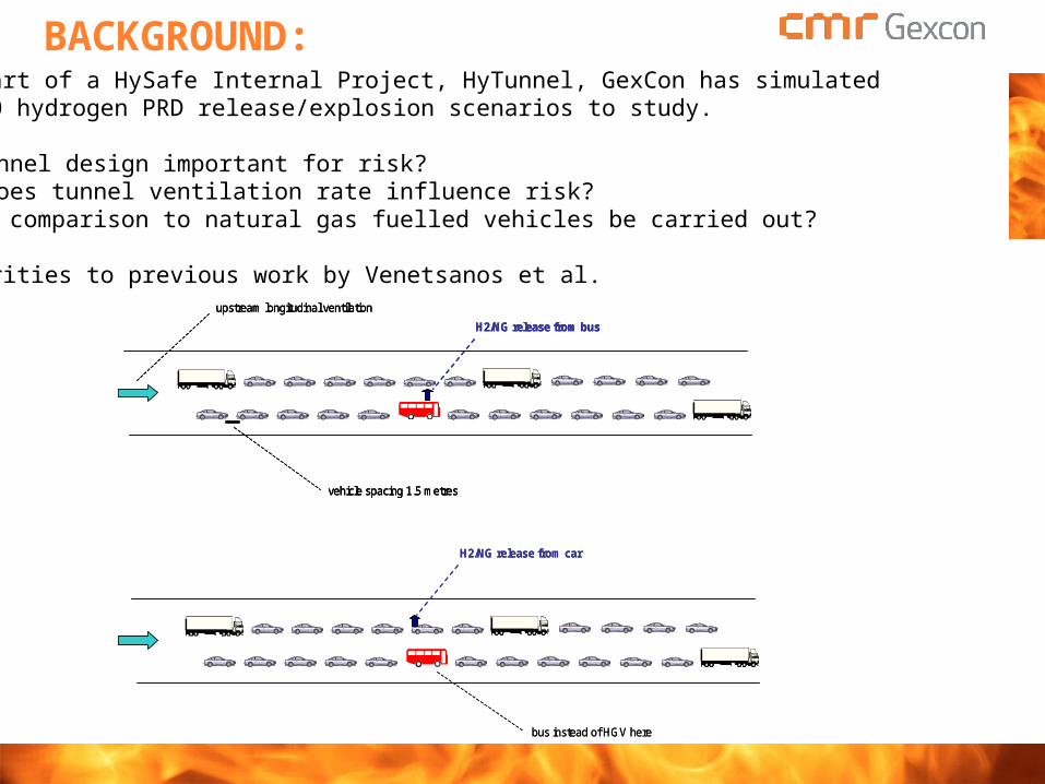
BACKGROUND:As a part of a HySafe Internal Project, HyTunnel, GexCon has simulated 200-300 hydrogen PRD release/explosion scenarios to study. Is tunnel design important for risk? How does tunnel ventilation rate influence risk? Can a comparison to natural gas fuelled vehicles be carried out?
Similarities to previous work by Venetsanos et al.upstream longitudinal ventilation
SCENARIOS STUDIED:The CFD software FLACS was applied (commercially available from GexCon). The following dispersion/explosion scenario variations were investigated: Two tunnel configurations 4 longitudal ventilation rates (0, 2, 3, 5 m/s) 9 PRD-release scenarios from buses or cars (assuming full tank)
Cross-section area = 60 m2
7.1 m
9.2 m 0.5 m
2 m
5.1 m7.1 m
9.2 m 0.5 m
2 m
5.1 m
9.2 m9.2 m 0.5 m0.5 m
2 m
5.1 m
2 m2 m
5.1 m5.1 m
Rectangular tunnel
Horse-shoe tunnel
Amount of gas is not 100% accurate for all cases, this has marginal impact on estimated risk (initial leak rate is more important)
RISK ASSESSMENT APPROACH:Different approaches were applied in risk-study worst-case ”realistic” worst-case (+ mitigation) probabilistic QRA approach
The probabilities indicated below was used for probabilistic QRA approach[Assumptions discussed in paper]
Cross-section area = 60 m2
7.1 m
9.2 m 0.5 m
2 m
5.1 m7.1 m
9.2 m 0.5 m
2 m
5.1 m
9.2 m9.2 m 0.5 m0.5 m
2 m
5.1 m
2 m2 m
5.1 m5.1 m
LEAK PROFILESTransient leak profiles representative for PRD releases were applied
Scenario 1
0,0
0,1
0,2
0,3
0,4
0,5
0,6
0 10 20 30 40 50
time (s)
Mas
s fl
ow
rat
e (k
g/s
)
H2, 350bar
H2, 350bar, ideal
H2, 700bar
H2, 700bar, ideal
CH4, 200bar
LH2 leak rate (11 g/s) is based on input from producer of car
Worst-case PRD release from buses assume relief from 4 cylinders at the same time
EQUIVALENT STOICHIOMETRIC CLOUD
During release calculations FLACS estimates:
Flammable volume (m3): Equivalent stoichiometric volume (Q9, m3) New volume exposed to flammable gas (m3/s)
Explosion in smaller stoichiometric cloud Q9 is assumed to give similar consequences as real non-homogeneous cloud.
Assumption needed to limit number of scenarios
Hydrogen gas dispersion in 72m3 room
0
10
20
30
40
50
60
70
80
0 100 200 300 400 500 600
Time (s)
Vo
lum
e (m
3)
Flammable volume
Q8 Expansion based
Q9 Expansion & reactivity
New flammable volume (1/s) x 100
max9 ( ) /( )flamQ V S E S E
Without this assumption we could end up with 1 million ignition scenarios in an extensive studye.g. 100 leak-cases x 1000 times of ignition x 10 ignition locations.
Q9 is an attempt to classify the reactivity (hazard) in a realistic released cloud[LFL distance or flammable volume is not a measure of consequence]
IGNITION INTENSITIES FOR PROB. QRA
Three ignition intensities are assumed:
Spontaneous ignition ignition very soon after release starts (50% of leaks assumed ignited first 5 seconds) caused by shock ignition, charging of particles/equipment, fire initiating PRD, engines or more
Continuous/constant ignition sources ignition by fixed ignition sources present all the time proportional to volume exposed for the first time to flammable volume last second
Intermittent (time-varying) ignition sources ignition by time-varying ignition sources proportional to flammable volume and exposure time.
Total ignition intensity for one leak scenario should be less or equal to ONE
The following assumptions were used in this study
WORST-CASE APPROACHWhat if all gas could mix to a stoichiometric gas cloud
Car LH2 (400m3)
Bus CGH2 & Car CGH2 (200m3) Car & Bus NG (400m3)
Bus CGH2 (800m3)
Bus NG (1600m3)
Quiescent
Pre-ignition turbulence
WORST-CASE APPROACHWhat if all gas could mix to a stoichiometric gas cloud25 kg hydrogen (1000 m3 cloud) [slightly larger than inventory].
WORST-CASE APPROACHWhat if all gas could mix to a stoichiometric gas cloud6.2 kg hydrogen (250 m3 cloud) [slightly larger than inventory of car or 1 cylinder bus].
ARE PREDICTED PRESSURES REALISTIC?
Ignited gas clouds
Overpressures
< 0.1m
0.5m 1.0m 2.5m 5m 10m 20m
2:2:1 Long 2:2:1 Long 2:2:1 Long
H2 incident C
Horseshoe E
0.050.03
0.110.07
0.170.11
0.290.19
0.500.52
1.010.38
1.290.77
3.222.96
2.664.28
6.539.97
NG incident CHorseshoe E
0.01.005
0.010.01
0.01 0.01
0.020.02
0.050.04
0.050.03
0.140.08
0.090.06
0.54 0.41
H2 incident C
Rectangular E
0.050.03
0.110.08
0.190.11
0.370.74
2.453.48
1.592.08
2.904.28
3.284.79
9.467.99
5.5711.7
NG incident CRectangular E
.005.005
0.010.01
0.020.01
0.03 0.03
0.060.04
0.050.04
0.21 0.08
0.140.12
0.670.39
0.600.41
NG-tunnel 18m cloud closed end ignitionFLACS Blind predictions 2006 0.6 to 0.8 barg
FLAME Facility H2
30m cloud
FZK InsHyde experimentsClouds < 0.5m3 Typical P = 0.05 barg
FLACS validated against several tests with similar dimensions and pressures Sandia FLAME Facility hydrogen tests 30m, ignition in closed end NIOSH Lake Lynn Experiments methane (blind predictions) Small scale tests with methane or hydrogen
Other scenarios seem much less dangerous (smaller leak rates)
High momentum & buoyancy quickly removes gas
DOES VENTILATION REALLY MATTER?Worst-case scenario with initial leak rate 0.94 kg/s (and 20 kg being released).
0 m/s
2 m/s
5 m/s
No wind Max flammable 1800 m3 Max equivalent 27 m3
2 m/s Max flammable 1500 m3 Max equivalent 30 m3
5 m/s Max flammable 1000 m3 Max equivalent 25 m3
REALISTIC WORST-CASE APPROACHCan dispersion simulations reduce the gas cloud size?Explosion with 25m3 cloud shown (less than 1 kg hydrogen)
DISPERSION: RESULTS
Worst-case volume of flammable cloud and equivalent stoichiometric cloud
Notice: worst-case scenario for NG:Much larger cloud for rectangular tunnel than horseshoe shape!
Dispersion (and explosion of dispersed cloud) Basic tests including numerical schemes SMEDIS evaluation project 1998 GexCon 50m3
Phase 3B (GexCon 50m3, Advantica 2600m3) Kit Fox (52 CO2 releases) Prairie Grass (37 SO2 tracer release) MUST (42 C3H6 tracer releases) NYC Urban dispersion project LNG (Burro, Coyote and Maplin Sands)
Manhattan geometry model
Basic tests: Standard numerical schemes will not give symmetrical impinging jet
FLACS-99
FLACS-98
Kit Fox: 75 large and 6600 small obstacles
MUST: 120 shipping containers
Phase 3B geometry FLACS flammable volume versus experiments in 20 tests
dispersion simulation : Flammble volume
0
500
1000
1500
2000
2500
1 2 3 4 5 6 7 8
8 : 1
m g
rid 9
9 : 1
m g
rid 10 11 12 13 14
14 :
1m g
rid 15 16
16 :
1m g
rid 17 18
18 :
1m g
rid 19 20
test number
Vo
lum
e (m
^3)
ObservedSimulatedrt.FUEL file
1998 study comparing observed and simulated concentration and explosion pressure
Coyote 5 LNG release simulation
FLACS DISPERSION VALIDATION
INERIS 6; DISPERSION BENCHMARKHySafe BLIND benchmark November 2005; 10-15 modelers delivered blind predictions Jan-March 2006; INERIS performed experiment
Scenario: Room 7.4m x 3.8m x 2.7m 4 minute leak 1 g/s 2 hour waiting time after leak Both GexCon and DNV used FLACS (good consistency) Diffusion phase well predicted
0
0.04
0.08
0.12
0.16
0.2
0 500 1000 1500 2000 2500 3000
Time (s)
H2
conc
entr
atio
n
Experiment
Simulations
0
0.01
0.02
0.03
0.04
0 500 1000 1500 2000 2500 3000
Time (s)
H2
conc
entr
atio
n
Experiment
Simulations
FZK IGNITED IMPINGING JETS
9 different vertical leaks (rate/momentum) studied in two geometry configurations April 2006, 300 FLACS blind simulations April-June 2006 test performed by FZK (report available to HySafe January 2007) Presented at ICHS2, San Sebastian, September 2007
0
20
40
60
80
100
0 0.1 0.2 0.3 0.4 0.5Q9 (m3)
Exp
losi
on P
ress
ure
(mba
r)
Real gas cloud (Hood)
Real gas cloud (Plate)
Stoichiometric gas cloud (Hood)
Stoichiometric gas cloud (Plate)
EXPLOSION OF IDEALISED GAS CLOUDS
WORST-CASE REALISTIC WORST-CASE
Realistic Worst-case ~ ear drum rupture level (+ windows will likely break) Most explosion scenarios may not be noticed by people inside the cars
MAX PRESSURE 0.1-0.3 BARG: - Is that realistic?Are the consequences underestimated?Will the Q9 precision influence the results ? Sensitivity studies igniting the worst-case scenario confirmed pressure level (ignition at 2.5s)
PRESSURE 0.1-0.3 BARG REALISTIC?
5 s after release 15 s after release
Low volume at concentration above 15%, and this is quickly reduced with time
Concentrations < 15% give limited contribution to overpressures (due to no congestion and low degree of confinement)
PROBABILISTIC STUDY => EXPECTED CONSEQUENCES FURTHER REDUCEDMaximum cloud size is only there for a fraction of the time likelihood for ignition before reaching maximum cloud may be high very transient release rates makes duration of worst-case cloud size limited This study has assumed worst-case fuel inventory, in real life there will be less fuel
Worst-case pressure range for ignition of real cloud within the jet
NG rectangular tunnel not included: Worst-case cloud => 0.3 barg
Mitigation (limit bus PRD rate to 0.23 kg/s) had significant risk reduction effect
CONCLUSIONSInteresting simulation study performed as part of HySafe IP02 (HyTunnel): Buoyancy / high momentum of leak => very strong dilution (even inside tunnel) Reactive gas only near leak at high momentum=> ventilation not important Worst-case effects comparable for NG and H2
Conclusions depend on input assumptions (mostly conservative):
Less dilution and potentially larger clouds can be seen if: PRD-release gets trapped and loses momentum Tunnel ceiling geometry / other release modes
Further reasons for caution: If releases may fill up volumes of cars, strong ”ignition” may be seen Light armature or fans may work as ”dense” congestion, may cause turbulence
Work is performed with a well validated CFD-Software FLACS Observations are generally expected to have validity Good precision of consequence tools is important to understand risk
FINAL COMMENTS
Thanks to European Commission Norwegian Research Council HySafe-partners Commercial FLACS software
QRA-method needs further development and improvements. Work to develop a better framework is being started in HySafe NoE => HyQRA IP03 IEA Task 19 experts group