35


SAND2002-2798 Unlimited Release Printed August 2002
r ALTERNATIVE WELLBORE LINING METHODS Problems and Possibilities
John T. Finger. Geothermal Research Department
Sandia National Laboratories PO Box 5800
Albuquerque, NM 87185-1033
Bill Livesay Livesay Consultants
126 Countrywood Lane Encinitas, CA 92024
ABSTRACT
A technology that would line a wellbore, at least partially, as it is drilled would have significant advantages compared to conventional steel casing cemented into place after completion of each hole interval. Cost savings from reduced lost circulation problems, better wellbore stability, lower probability of stuck pipe and other trouble, and the ability to seal certain zones without a full string of casing would be a major improvement to the economics of geothermal drilling.
This report identifies a number of specific problems that could be solved or mitigated by alternative wellbore-lining techniques. The report also describes the state-of-the-art for four kinds of wellbore lining and draws general conclusions about the costs and benefits of each of these systems. There are recommendations about which activities should be pursued by DOE-sponsored laboratories to advance the technology in the case of each technique.
I .
II .
III .
Iv .
V .
VI .
VII .
VIE
Ix . X .
XI .
XII .
XIII .
CONTENTS
Executive Summary ......................................................................................... 5
Introduction ..................................................................................................... 5
. . Study ObJeCtlveS ............................................................................................... 6
Problem identification and description ............................................................ 6
Problem quantification .................................................................................. 11
Lining alternatives ......................................................................................... 12
Application scenarios .................................................................................... 19
State-of-the-art and other technology needs .................................................. 21
Supporting/enabling technologies ................................................................. 22
Conclusions ................................................................................................... 25
Recommendations ......................................................................................... 27
Sources .......................................................................................................... 29
References ..................................................................................................... 31
4
I. EXECUTIVE SUMMARY
A technology that would line a wellbore, at least partially, as it is drilled would have significant advantages compared to conventional steel casing cemented into place after completion of each drilling interval. Cost savings from reduced lost circulation problems, better wellbore stability, lower probability of stuck pipe and other trouble, and the ability to seal certain zones without a full string of casing would be a major improvement to the economics of geothermal drilling.
This report identifies a number of specific problems that could be solved or mitigated by alternative wellbore-lining techniques and divides those techniques into four types:
Continuous Wellbore Lining while Drilling (WLD) with chemical means Continuous WLD with steel (or other metal) means
a Step-Wise Lining (SWL) with chemical means, and Step-Wise Lining (SWL) with steel.
The report also describes the state-of-the-art for these four kinds of wellbore lining and draws general conclusions about the costs and benefits of each of these systems. There are recommendations about activities that should be pursued by DOE-sponsored laboratories to advance the technology in the case of each technique.
II. INTRODUCTION
When wells are drilled to depths of more than a few hundred feet, conventional practice is to set successive, separate strings of casing as the well gets deeper. The depth of each string is determined by several factors, including rock properties (fracture gradient, sloughing, swelling, unstable, or unconsolidated formation), formation fluids (pore pressure much less or much greater than dnlling fluid pressure), or even regulatory requirements (most agencies require that at least 10% of the wellbore always be behind casing). These criteria apply to most kinds of drilling - onshore or offshore oil and gas, geothermal, or even minerals exploration - and they are further complicated by the ever- present possibility of unexpected trouble, which can mean an extra string of casing is run to prevent or remedy some downhole problem. This is expensive for more than one reason, as described in more detail below.
There are three important implications of this process: Because each casing string limits the diameter of the drill bit and successive casing strings that can pass through it, the hole diameter decreases as the well gets deeper. Because of casing costs and diameter reduction, it is beneficial to make the intervals between casing points as long as possible. Problems or trouble most often occur while drilling the wellbore intervals between casing points.
The two latter points counter each other - it is highly desirable to drill long intervals between running successive casings, but doing so greatly increases the probability of trouble. If a "contingency string" is needed to isolate a troublesome zone, this imposes a
5

significant cost for the additional casing and cementing and for the necessity of larger diameter casing above the contingency string, so that the required bottomhole diameter can be preserved at the designed dimension.
No matter what the arena, the aim of research and development is to reduce the cost of well development, but new technology is usually most beneficial in high-cost ventures. The problems in standard, relatively shallow, relatively cheap oil and gas drilling can usually be prevented or mitigated by good planning and attention to detail, so an improved wellbore lining system might have little impact on these generally trouble-free wells. On the other hand, deep oil and gas drilling, where high temperatures and high-pressure zones are common, has many situations that lead to additional casing strings that put the problem zone behind pipe. Geothermal wells have high temperatures, hard, abrasive rocks, and lost circulation that inflate their cost well above an onshore oil and gas well of the same depth, while offshore drilling is often an order of magnitude more expensive than land drilling.
For geothermal wells, the chief issue is severe lost circulation. Proper casing and cementing practice are severely compromised by lost circulation and/or well bores that have low fracture gradients.
ID. STUDY OBJECTIVES
If a method of sealing or lining the wellbore, with or without steel casing, while drilling were possible, then many advantages would accrue. Investigation of that possibility, stimulated by a National Advanced Drilling and Excavation Technologies (NADET) research topic specific to lost circulation in geothermal wells, defined the original objectives of this study and report.
1. Identify the well drillingkonstruction problems that can be reduced or eliminated
2. Develop a list of potential lining technologies, including those in current by development of wellbore lining techniques.
commercial development, that are candidates to solve the identified problems. Define the development needs that confront each candidate. Analyze the list to determine any attractive candidates that are not being pursued by industry. [we should note that at least two candidates for lining the wellbore - drilling with casing and expandable tubing - have become much more mature during this study. These commercial products and services are available now and are undergoing further development. Neither is aimed at the geothermal lost circulation problem.]
3. Based on the development needs identified in Objective 2 above, recommend a program to address development topics in wellbore lining. This could be either a set of technology developments carried out by National Laboratories or certain supporting technology activities in support of industry development. Describe any additional benefits from wellbore lining techniques that appear during the study.
IV. PROBLEM IDENTIFICATION AND DESCRIPTION
A number of costly problems could be eliminated or alleviated by a wellbore lining while
6

t
drilling (WLD) system. Although the original objective was specific to the problem of severe lost circulation when drilling geothermal wells - and this application is still highly relevant because lost circulation is the most expensive problem in eothermal drilling, sometimes representing as much as 15% to 20% of total well cost’$ - a closer look at the functions of WLD systems has shown that it would also be beneficial in several other situations. Each of these cases is described in more detail below.
Lost circulation is the condition in which drilling fluid, because of the formation fluid’s low pore pressure, flows into the formation rather than returning up the wellbore annulus. This loss can reach extremely high rates, up to 1000 gallondminute, and is harmful for several reasons.
If the drilling fluid fails to clean the hole and return cuttings to the surface, the chips can fall back on the bottom-hole assembly and stick the drilling assembly. Drilling fluid, especially in many high-temperature formulations, is expensive and losing it to the formation instead of re-circulating it is costly. In geothermal wells, the production zone is usually a lost-circulation zone, so it is sometimes difficult to cure a harmful lost circulation zone while preserving its productive potential. Lost circulation can suddenly lower the fluid level in a well. Decreasing the static head of drilling fluid in a hot formation can allow the mud to flash into steam and may cause a loss of well control. This can occur either in productive or non- productive zones. In the intervals that are not to be produced, the lost circulation zone must be “sealed” to provide a wellbore that can be cased and cemented to the surface. (See “Difficult Cement Jobs” below.) The problems of sealing the zone to allow for cementing the casing are a major part of lost circulation problem. Placement of lost circulation materials (LCM) is difficult because the top and bottom of the loss zone are often not well known. The LCM or cement being used to heal the loss zone are especially likely to migrate away from the targeted placement zone if drilling has continued well past it into another loss zone, or if there is considerable rat hole below the original loss zone.
Uncontrolled loss to the formation places a costly limit on drilling. Drilling without returns may not be an acceptable approach for the reasons given above.
In many areas where geothermal drilling is done, water is in short supply.
The use of (lighter) aerated drilling fluids to combat lost circulation will sometimes permit drilling ahead, but does not solve the need for a competent wellbore during cementing (see below). The tendency toward lost circulation is aggravated by the pressure imbalance between the relatively cool (denser) column of drilling fluid and the hot (less dense) geothermal fluids in the formation.
.stdqpe: In addition to the “mechanical” sticking caused by chips and cuttings collecting on top of the drilling assembly (described above), the pipe can also be held against the wellbore wall by differential between the drilling fluid pressure and the pore pressure. Many intervals encountered in geothermal drilling are under-pressured, This means that the pore pressure is less than that of a column of cooler water at the same depth.
7
Differentially stuck pipe will not rotate nor can pulling move it. This, of course, cannot happen if the wellbore formation is sealed or lined.
-: Wellbore instability has a number of effects, which can cause widely varying kinds of problems.
The wellbore may be mechanically unstable because the rock is fractured or it can occur due to degradation of the wall due to the invasion of fluids from the drilling fluids. The wellbore wall, especially in formations with significant clay content, may become weakened by adsorption of water into the clay of the wellbore rock. Sloughing or unconsolidated formations can aggravate hole-cleaning problems, can fall in around the drill pipe to stick it, and can wash out to a very large diameter. Large washouts not only complicate cementing, but lower fluid velocity in the larger diameter reduces cuttings-carrying capacity.
stick the pipe or prevent running casing. Swelling or squeezing clays may reduce hole dameter to a point that will either
Each of these problems will make it difficult to clean the hole of drilled cuttings and will ultimately make cementing the casing or liner in place very difficult.
v: Because geothermal casings must be cemented completely back to surface, there is often a problem getting a competent cement job where the formations have shown either low strength or lost circulation. This results from the cement’s higher density, and thus higher static head, relative to drilling fluid. It is also critical that no water is trapped between the cement and casing, for it will either flash to steam or the liquid will thermally expand, with the possibility that either can collapse the casing as the wellbore goes through its temperature cycles.
Methods using very light-weight cement (less than 12 ppg) have sometimes been successful in low pressurdlow strength zones. Lost circulation during cementing often results in incomplete cement jobs that must be repaired by:
Top jobs, where the cement is placed into the annulus between casings by small- diameter tubing, or Perforation and squeezing, where the inner casing is perforated above the top of the incomplete cement and additional cement is displaced through the holes up the annulus. This method has the weakness that it depends only on the cement (not steel) to seal the perforations and is therefore vulnerable to cement degradation.
Failed cement jobs are very difficult to repair.
The need for a full-length cement sheath creates other problems that dictate how the well is drilled and completed. Standard geothermal practice is that lost circulation zones must be fixed as they are encountered so that they will not interfere with the cementing work. This is ex ensive because some lost circulation zones require 10 to 20 cement plugs to seal them and allow drilling to resume. Each plug requires cementing the loss zone and waiting on cement until it is sufficiently set to re-enter the well and to drill ahead. This means that even a one-plug lost circulation seal will take 12 to 24 hours. Foam cement (the cement is foamed with nitrogen or air bubbles in the cement) is an approach that has been tried successfully. There are some concerns about the fact that the foamed cement is hard
?
8
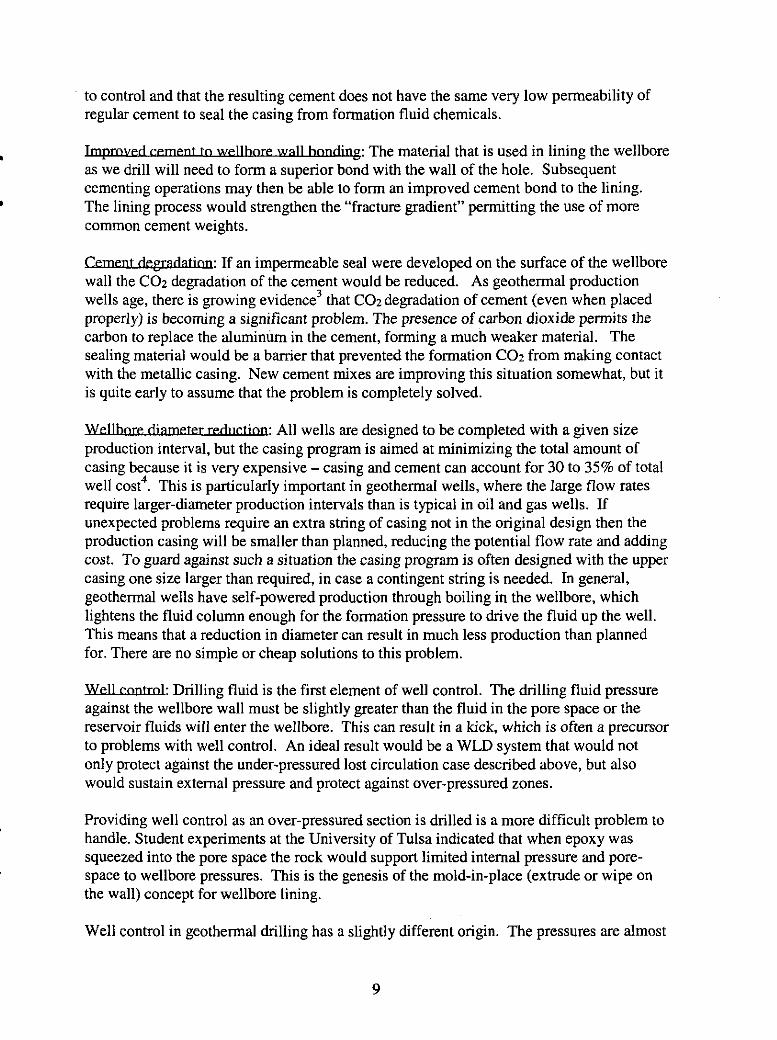
to control and that the resulting cement does not have the same very low permeability of regular cement to seal the casing from formation fluid chemicals.
p: The material that is used in lining the wellbore as we drill will need to form a superior bond with the wall of the hole. Subsequent cementing operations may then be able to form an improved cement bond to the lining. The lining process would strengthen the “fracture gradient” permitting the use of more common cement weights.
-: If an impermeable seal were developed on the surface of the wellbore wall the C02 degradation of the cement would be reduced. As geothermal production wells age, there is growing evidence’ that C02 degradation of cement (even when placed properly) is becoming a significant problem. The presence of carbon dioxide permits the carbon to replace the aluminum in the cement, forming a much weaker material. The sealing material would be a barrier that prevented the formation COZ from making contact with the metallic casing. New cement mixes are improving this situation somewhat, but it is quite early to assume that the problem is completely solved.
P: All wells are designed to be completed with a given size production interval, but the casing program is aimed at minimizing the total amount of casing because it is very expensive - casing and cement can account for 30 to 35% of total well cost”. This is particularly important in geothermal wells, where the large flow rates require larger-diameter production intervals than is typical in oil and gas wells. If unexpected problems require an extra string of casing not in the original design then the production casing will be smaller than planned, reducing the potential flow rate and adding cost. To guard against such a situation the casing program is often designed with the upper casing one size larger than required, in case a contingent string is needed. In general, geothermal wells have self-powered production through boiling in the wellbore, which lightens the fluid column enough for the formation pressure to drive the fluid up the well. This means that a reduction in diameter can result in much less production than planned for. There are no simple or cheap solutions to this problem.
W e l h m t d Drilling fluid is the first element of well control. The drilling fluid pressure against the wellbore wall must be slightly greater than the fluid in the pore space or the reservoir fluids will enter the wellbore. This can result in a kick, which is often a precursor to problems with well control. An ideal result would be a WLD system that would not only protect against the under-pressured lost circulation case described above, but also would sustain external pressure and protect against over-pressured zones.
Providing well control as an over-pressured section is drilled is a more difficult problem to handle. Student experiments at the University of Tulsa indicated that when epoxy was squeezed into the pore space the rock would support limited internal pressure and pore- space to wellbore. pressures. This is the genesis of the mold-in-place (extrude or wipe on the wall) concept for wellbore lining.
Well control in geothermal dnlling has a slightly different origin. The pressures are almost
9
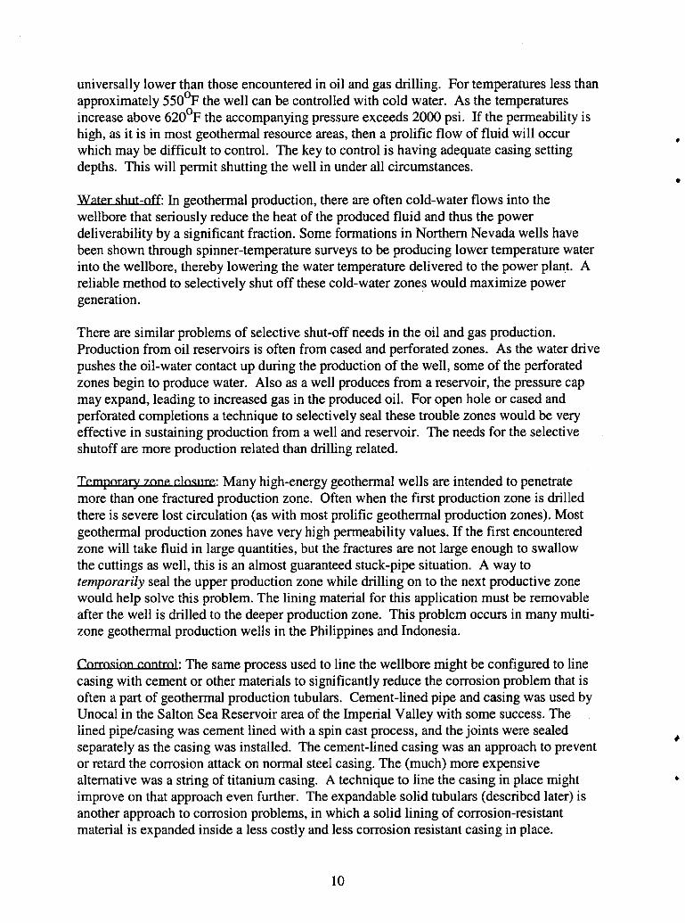
universally lower than those encountered in oil and gas drilling. For temperatures less than approximately 550°F the well can be controlled with cold water. As the temperatures increase above 620°F the accompanying pressure exceeds 2000 psi. If the permeability is high, as it is in most geothermal resource areas, then a prolific flow of fluid will occur which may be difficult to control. The key to control is having adequate casing setting depths. This will permit shutting the well in under all circumstances.
Y & x h t d t In geothermal production, there are often cold-water flows into the wellbore that seriously reduce the heat of the produced fluid and thus the power deliverability by a significant fraction. Some formations in Northern Nevada wells have been shown through spinner-temperature surveys to be producing lower temperature water into the wellbore, thereby lowering the water temperature delivered to the power plant. A reliable method to selectively shut off these cold-water zones would maximize power generation.
There are similar problems of selective shut-off needs in the oil and gas production. Production from oil reservoirs is often from cased and perforated zones. As the water drive pushes the oil-water contact up during the production of the well, some of the perforated zones begin to produce water. Also as a well produces from a reservoir, the pressure cap may expand, leading to increased gas in the produced oil. For open hole or cased and perforated completions a technique to selectively seal these trouble zones would be very effective in sustaining production from a well and reservoir. The needs for the selective shutoff are more production related than drilling related.
-: Many high-energy geothermal wells are intended to penetrate more than one fractured production zone. Often when the first production zone is drilled there is severe lost circulation (as with most prolific geothermal production zones). Most geothermal production zones have very high permeability values. If the first encountered zone will take fluid in large quantities, but the fractures are not large enough to swallow the cuttings as well, this is an almost guaranteed stuck-pipe situation. A way to temporarily seal the upper production zone while drilling on to the next productive zone would help solve this problem. The lining material for this application must be removable after the well is drilled to the deeper production zone. This problem occurs in many multi- zone geothermal production wells in the Philippines and Indonesia.
The same process used to line the wellbore might be configured to line casing with cement or other materials to significantly reduce the corrosion problem that is often a part of geothermal production tubulars. Cement-lined pipe and casing was used by Unocal in the Salton Sea Reservoir area of the Imperial Valley with some success. The lined pipekasing was cement lined with a spin cast process, and the joints were sealed separately as the casing was installed. The cement-lined casing was an approach to prevent or retard the comosion attack on normal steel casing. The (much) more expensive alternative was a string of titanium casing. A technique to line the casing in place might improve on that approach even further. The expandable solid tubulars (described later) is another approach to corrosion problems, in which a solid lining of corrosion-resistant material is expanded inside a less costly and less corrosion resistant casing in place.
10

summa^: The ability to seal the wellbore to lost circulation as the well is being dnlled would be a major breakthrough to the geothermal industry. Even though the ultimate tool may seal immediately behind the bit while drilling, devices are currently commercially available that seal the wellbore in a step-wise approach and may have great utility for fighting severe lost circulation problems.
V. PROBLEM QUANTIFICATION
To assess the effect on well cost of reducing lost circulation, a generic geothermal well was simulated with the Sandia well-cost model. A description of the well and its lost circulation events is given in the table below.
Table 1 - E f P
prof‘e, ,5500 - 7500’ 1500 - 5500’ 500 - 1500’. 50 - 500’ cost ~~ 12.25/9.63” 17.5113.38’’
2.538 0 2 3 5 Severe LC 2.234 0 1 2 2 Moderate LC
lost circulation 1,968 0 0 0 0 Baseline - no C$k) a
TOD hole Total.wel1 ,Production Intermediate Intermediate
holelcasine 26,20,,
This shows that eliminating lost circulation from a well with severe problems can save more than 20% in well cost. This order of magnitude is supported by field experience with an exploration well2 where just the cost of cementing services for lost circulation plugs exceeded a half-million dollars. This is also a conservative calculation in that it does not claim any benefits for eliminating other trouble such as stuck pipe. If we assume half this benefit as an average for 20 geothermal wells per year, total annual savings would exceed $5 million.
This kind of calculation also provides a bound to acceptable cost for a system that would eliminate lost circulation. If the system cost $100,000 per well to provide the service, it could still save $150,000 - 400,000 per well, which might apply to at least 50% of the production wells drilled. Because the incidence of lost circulation is much lower.there, wells in the Imperial Valley would not benefit as much as wells at Coso, Utah, Northern Nevada, near Geysers wells and young volcanics, such as those on the island of Hawaii.
-: Infill drilling in fields such as Cos0 must pass through depleted production zones. While this is similar to the low pressure of a geothermal resource, it causes additional problems with differential sticking and lost circulation.
w: Wells in Indonesia and the prolific fields on Leyte in the Philippines often have more than one productive interval. As drilling progresses past the first production zone, there is severe loss circulation, which often sticks the drilling assembly. In order to drill on to the next production horizon it is necessary to close the
11

shallower loss zone while drilling on to the deeper one. The seal must be temporary so that after the deeper production zone is penetrated the upper zone can be reopened for production. Current techniques use a steel liner that is cemented only on the bottom 50 or so feet. To reopen the zone, the liner cement is acidized away and the hole cleaned out by drilling. Using a fiberglass section or an aluminum section that can be pulled and the hole cleaned up for the final production completion is also a possible approach.
Flat time is defined as any time during which the hole is not being advanced. An industry forum5 presented a 250-well database that showed FT represents 65- 83% of total time the rig is over the hole, and that tripping and casing installation together were 22-33% of total rig time. These cost categories, particularly for offshore operations, are clearly targets for improvement.
VI. LINING ALTERNATIVES
If we consider only the lost circulation problems that originally motivated this repon, then the standing liquid level in the wellbore can characterize the extent of the lost circulation, which is controlled by pore pressure and transmissivity of the formation. In general, especially in a geothermal well, the liquid (i.e., drilling fluid) level will be considerably below the ground level, indicating that the wellbore’s pore pressure will not support a full fluid column. An option, however, is to drill with a low-density fluid that has at all points in the wellbore a fluid pressure equal to or lower than the pore pressure. In this case, there would be no lost circulation and the hole would still be cleaned of cuttings, although this method would not address the problem of cementing casing once reaching the proper depth. Such low-density drilling fluids -aerated mud, foam, water-based mud with light solids such as glass micro balloons, and air - have been tried in geothermal drilling with some success in the lost-circulation area, but are expensive and are not fully satisfactory because of the remaining cementing deficiencies. These systems also fail to mitigate the other problems described above.
Lining concepts that could mitigate wellbore problems could take many different forms, but a useful way of classifying them is by their functional ability to line the hole continuously at a point very near the bit. For convenience, we will call systems that can put continuous lining in the hole at or near the bit, Wellbore-Lining while Drilling (WLD) systems and those that introduce the lining in discrete intervals, Step-Wise Lining (SWL).
There are major subsets within each of these classifications, based on whether the wellbore is actually sealed (made impermeable) or just constrained by a mechanical barrier. Each of these categories is discussed in more detail below, with attention to which of the identified problems each technique might be effective in mitigating. The category labels refer to Table 2 below, which ranks the alternatives in terms of their effectiveness in solving the variety of problems described above.
3: The optimum capability for a WLD system is emplacement of a mechanically strong, impermeable, chemically impervious wellbore lining with small enough thickness that it would not hinder withdrawal of the drill
. . . .

bit. A concept called “Subterrene”, developed by Los Alamos in the 1970s, used an electrical heater to melt rock, which then became a glassy lining on the wellbore wall and fulfilled many of these requirements. Although this concept went as far as lab-scale tests, there were many problems (not all rocks were suitable for melting, glassy lining sealed up production zones, very large power transmission to downhole) that discouraged further development4.
If we consider the sealing aspect of a WLD system, we can envision the application, just behind the bit, of a flexible, perhaps polymer-like, substance that would adhere to the wellbore wall or, even better, penetrate the formation, and would have enough strength to resist internal or external pressure differential. In many ways, this is the most intriguing solution, for it has the potential to solve so many of the problems we have considered.
In an ideal case, the sealing WLD system would have these attributes: a It would allow drilling the well at rates comparable to current technology.
It would provide an effective seal on the wellbore wall that, at least temporarily,
a It would not interfere with cuttings removal. a It would create a lining rugged enough to survive subsequent drilling (drill string
rotation) and casing installation. In the most optimistic case, the lining could replace part of the casing.
remedied or mitigated lost circulation and/or well control problems.
It would not be so costly and complex as to preclude its use.
This ideal system would, on the other hand, face the following development challenges: a A conduit, in parallel with the drilling fluid circulation, would be necessary to
continuously deliver the necessary materials and power to creatdinstall the wellbore lining.
annulus most likely will be necessary.
or underreaming bit will be necessary.
with the seal creation. This path cannot create a flow restriction that will overpressure and break down the formation at the bit. (Reverse circulation may be part of the solution to this problem.)
quickly enough to provide an intemaVexternal pressure seal immediately. This may require a two-component polymer for the quick set.
drilling where fracture apertures are sometimes inches to feet across.
wall. It must not be circulated back to the surface or adhere to the drill string or other downhole components.
A partial seal between the lining-creation mechanism and the balance of the well
a Unless the lining is very thin or has penetrated the formation, a retractable-diameter
The system must provide an alternate path for the cuttings that does not interfere
a If the lining material is transported or created downhole as a liquid, it must set
The lining material must be able to bridge large gaps, especially for geothermal
a Perhaps most difficult of all, the lining material must adhere only to the wellbore
A sealing WLD system would be extremely versatile, because it would provide so many different benefits.

1. With its ability to overcome overhnder pressure gradients, it could eliminate casing strings set to meet pressure criteria. In the offshore application, this could save $500k in casing cost and $lM in associated rig cost and services.
2. It would eliminate or greatly reduce the lost circulation problem in geothermal drilling, particularly in comparison with the standard cement plug technique that is now standard. The WLD system would solve much of the placement problem that plagues cement, which is often ineffective because the cement does not remain in place long enough to seal the wellbore. In addition, cement often does not penetrate the wellbore wall or does not bond adequately with the wall, so that the seal is lost when the cement is drilled out.
shales) and mechanical (sloughing, caving) wellbore instability.
very expensive problem.
formation fluids.
cement required.
consistent underbalanced drilling, with consequent improvements in penetration rate and productivity.
protection to drilling fluids, downhole tools, and steering or logging electronics in high-temperature formations.
3. An impermeable, reasonably strong, seal would eliminate chemical (swelling
4. It could shut off shallow water flows in offshore drilling. This is a common and
5. With sufficiently low permeability, it could protect tubulars against corrosion from
6 . It could produce a much better quality cement job and could reduce the amount of
7. If the system had sufficient resistance to formation pressure, it could allow
8. A lining material with low thermal conductivity could provide some thermal
Patents exist on systems that construct rigid, sealed cement sheaths inside wellbores or line them with spiral metal strips as the bit advances, but these mechanisms are extremely complex and, to the authors' knowledge, have not been reduced to practice.
An effective chemical WLD system could have significant cost reduction possibilities, depending on what we assume its capabilities to be. The least demanding requirement would be simply to seal the wellbore against lost circulation, allowing trouble-free drilling and cementing casing, but we can also imagine a much sturdier lining that could withstand geothermal production flow and could essentially replace steel casing altogether. Several variations of these possibilities were simulated with Sandia's well-cost model, starting with a well description similar to that used in Table 1, to assess the cost impact - results are given in Table 1-a below. Definition of the different cases:
A. baseline trouble-free well with standard casing profile and no lost circulation B. same well profile as baseline, but with lost circulation events in each interval,
treated by cementing C. same casing profile and LC in upper two intervals; drill 12-1/4" hole through third
interval with chemical WLD and continue drilling to production depth for 12-1/4" production diameter - eliminate one casing string
D. 13-3/8" casing in first interval; drill 12-1/4" hole with chemical WLD through
14
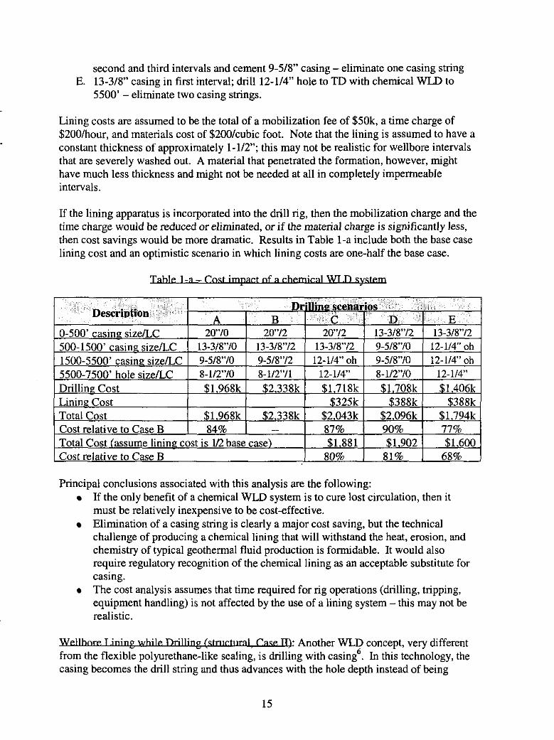
second and third intervals and cement 9-5/8” casing - eliminate one casing string
5500’ - eliminate two casing strings. E. 13-3/8” casing in first interval; drill 12-1”’ hole to TD with chemical WLD to
Lining costs are assumed to be the total of a mobilization fee of $SOk, a time charge of $200/hour, and materials cost of $200/cubic foot. Note that the lining is assumed to have a constant thickness of approximately 1-1/2”; this may not be realistic for wellbore intervals that are severely washed out. A material that penetrated the formation, however, might have much less thickness and might not be needed at all in completely impermeable intervals.
If the lining apparatus is incorporated into the drill rig, then the mobilization charge and the time charge would be reduced or eliminated, or if the material charge is significantly less, then cost savings would be more dramatic. Results in Table 1-a include both the base case lining cost and an optimistic scenario in which lining costs are one-half the base case.
Tahle 1 - - a Cod W.l3 sg&m
Principal conclusions associated with this analysis are the following: If the only benefit of a chemical WLD system is to cure lost circulation, then it must be relatively inexpensive to be cost-effective. Elimination of a casing string is clearly a major cost saving, but the technical challenge of producing a chemical lining that will withstand the heat, erosion, and chemistry of typical geothermal fluid production is formidable. It would also require regulatory recognition of the chemical lining as an acceptable substitute for casing.
equipment handling) is not affected by the use of a lining system - this may not be realistic.
The cost analysis assumes that time required for rig operations (drilling, tripping,
. . . . : Another WLD concept, very different b n g with casing6. In this technology, the casing becomes the drill string and thus advances with the hole depth instead of being
1s

emplaced as a separate process. This system makes hole either by placing cutters on the casing shoe and rotating the casing or by latching a retrievable drilling motor with a retractable bit into the bottom of the casing and using that to cut rock. In commercial operation, a combination of casing rotation and motor-powered bit rotation is now being used. The dnlling with casing approach can be effective at saving tripping time and will be quite effective for improving wellbore stability. A system developed by TESCO’ may prove to be quite effective in dealing with shallow water flows in deep water drilling. Shallow water flows are a serious problem in deep water offshore drilling in the Gulf of Mexico and other offshore drilling targets.
The goal of the TESCO casing-drilling program is to reduce the cost of a well by as much as 30%. The casing-drilling approach does not solve lost circulation problems as much as it eliminates trips, makes it possible to drill and rotate in zones of unstable wellbores, and makes bit changes faster by retrieving and replacing the biddrilling assembly on a wireline. Casing drilling has as its main attraction the possibility of significantly reducing the time and cost to drill, run casing, and cement the casing in place. The motivation is the reduction of flat time on the drilling curve. Drilling with the casing eliminates a trip out of the hole with drill pipe and a trip in with casing for each casing point reached, but for this system to be time-effective it must have a rate of penetration substantially the same as conventional drilling with a bit. It also offers some support for wellbore stability issues. For finding the proper casing point the system appears to provide a tool to continue to move forward when seeking a competent casing seat.
Drilling with casing provides good mechanical strength to support the wellbore, and at least mitigates wellbore flow (lost circulation or luck). Its lack of sealing means that it is not a long-term solution to flow problems, because it does not address the problem of cementing loss zones once the casing is at the design depth*.
. . n-W1 s c h m n g - w : is commercially done by at least two suppliers, although the actual mechanisms used by them are quite different. Weatherford provides a casing patch’ with longitudinal corrugations that is expanded to a larger diameter by a mandrel forced through the inside. The outside of the patch is coated with an epoxy resin, so some sealing capability is available.
This tool is designed for use inside casing - Weatherford did not know of its use in open hole”, and it is not clear whether this can be done. The casing patch, as designed, appears to require an elastic metallic host for effective application. The elastic response of the host is used to hold the patch in compression. The patch’s diameter increase is limited, however, because the expander mandrel must fit through the casing already in place. An additional limitation is that the system has very little tolerance for unwanted material between the patch and the host casing.
US Patent 5,366,012 by Lohbeck of Shell is the underlying technology for a completely different kind of expanding tubing that is available in both perforated or slotted tubulars and in solid expandable tubulars. Both product types use an “expander cone” forced through the tubing to enlarge cylindrical tubing to a greater diameter. The two product
16

types are licensed to different service companies, and each can be used either in open hole or inside casing. The perforated expanding tubulars” originally offered by Petroline, now acquired by Weatherford, use a combination of geometry and metallurgy that allows the mandrel to expand the inside diameter of the tubular to a larger dimension than the mandrel. This could be a significant benefit, in that a tubular and mandrel can be run in below existing casing and then the tubular can be expanded to the same, or larger, ID as the casing, thus losing no casing diameter. Typical “excess expansion” is about 4-696 of inside diameter. The down side of the perforated tubing is that it must be cemented in place because the joints cannot withstand torque, but if a cement job can be placed reliably then the tubing will not be needed to cure lost circulation. The perforated tubing still has potential to solve wellbore stability problems and the tubing can be run, expanded, and cemented in one pass, so that it is fairly quick to emplace. Current availability includes pipe sizes up to 13-3/8” casing. These tubulars are also available with sealing material on the outside surface.
The solid tubulars offered by Enventure are available in expanded sizes up to slightly more than 14” ID, and that pipe will pass through 16” base casing before expansion. Even though the expanded ID will not pass the standard 14-3/4” bit used to drill out of 16” casing, a trouble zone below that casing size could be underreamed and have a solid tubular expanded in it without the necessity of cement and a custom 14” bit couId be used to drill ahead. Non-standard bit sizes are readily available and the difference between the bit diameters would not be enough to interfere with running 11-3/4” casing for the next string.
Performance ratings for the expandable tubulars are an important issue. The burst, collapse and tensile capabilities of the post-deformed pipe will determine whether the pipe can be used for that application. The plastic deformation of the tubing results in a cold-worked steel. Literature for the solid expandable tubulars shows that the post yielded burst rating (compared to the rating before expansion) is reduced by 10-20%, but collapse is reduced by approximately 50%. For geothermal applications this would be very important since geothermal casings are usually larger diameter than oil and gas. In many geothermal casing designs the coliapse rating is the controlling factor that determines casing setting depths. The casing collapse issue could be moot if the expandable tubular was simply used as a wellbore patch, with conventional casing cemented inside it as the final production string.
Recent progress in the development of the expandable casing system is also a way in which to mitigate the corrosion problems in the wellbore tubulars. Cladding methods were used by Chicago Bridge and Iron (Horton-clad materials) to protect storage tanks from internal corrosion by applying a layer of corrosion resistant metal to a less costly metal sheath. This approach is possible with the expandable casing concept. A corrosion resistant layer can be applied to the wellbore independent of the base lining material. The expandable casing approach could be used to line the hole with a corrosion resistant layer inside the mold-as-you-drill lining method. If testing and experience show that the lining can be used to reduce the corrosion attack on the metals as well as eliminating the cement and the subsequent C02 attack, the allowable cost to combine the benefits of both methods would be much greater.
In all these scenarios, the central principle of using expandable tubulars is to preserve the wellbore diameter below the previous casing. For example, if we encounter a trouble (lost circulation, high pressure, etc.) zone while drilling 12-1/4” hole out of 13-3/8” casing, and we wish to use expandable tubulars to treat this problem, then it will require underreaming the trouble zone to a diameter at least 13-3/8” or larger so that the tubing can be expanded into it and then continue drilling 12-1/4” hole.
The major benefit of the Shell-related processes is the ability to drill near-single-diameter wellbores below the surface casing. This is estimated to save as much as 50% on offshore applications by eliminating multiple casing strings while maintaining the wellbore diameter as large as possible.
Caw lV): SWL systems using chemical liners are theoretically feasible and could be reasonably analogous to existing technology. Sandia has experimented with drillable straddle packers” and polyurethane grout13 for sealing loss zones, although the straddle packer has only been demonstrated in experiments, and the polyurethane has had one field demonstration. Although the experience with polyurethane has shown promise as a downhole sealing material, it is not clear that the properties can be engineered to provide the type of material needed as at least a temporary wellbore lining, especially at temperature.
If we are not to depend just on the chemical sealing in the formation fractures, the chemical SWL could also be used as described for the structural SWL, that is a trouble zone could be underreamed and the entire wellbore filled with something like polyurethane grout, which could then be drilled out, leaving the existing wellbore diameter with a sealed lining in the trouble interval. If the underreamed interval were long, there would be problems in keeping the bit centralized to leave the lining completely around the wellbore circumference, but this is at least a possibility.
Pipeline-lining technology is also very mature and, at least in principle, could be applied to open-hole sections of a well. Open-hole application of the chemical SWL system will be somewhat more challenging. Each of these chemical-lining systems has the same pros and cons discussed in the WLD section -they are effective in situations where the wellbore pressure exceeds the pore pressure, but not the converse.
All of the SWL systems have one major advantage - they can be used to treat the trouble zones, not the entire wellbore - and one major disadvantage -we still have long sections of open hole while drilling.
Other SWL concepts involve inflatable wellbore patches that can be placed using drill pipe or some even on wireline. These systems are a bit less robust than those that we have focused on in the descriptions. The polymer systems replace cement as the material to seal the wellbore, which could produce time savings if the polymers are designed to harden much faster than cement.
18

A summary of which lining methods are effective in addressing the identified problems is given below in Table 2. We should also note that scoring in Table 2 assumes that all methods can be made to work at geothermal temperatures, which may turn out to be the most difficult development task for any of the techniques.
m 2 w p
Case I WLD chemical Scoring code E = effective = 2 points Case II: WLD steel P =partially effective = 1 point Case III: SWL steel I = ineffective = 0 points Case IV: SWL. chemical ? = unknown
4
*
VII. APPLICATION SCENARIOS
Every different drilling and producing environment will emphasize different performance requirements. The application scenarios considered here include geothermal low temperature, geothermal high temperature, oil and gas, high pressure/deep gas wells, and offshore drilling operation needs.
The high downhole temperatures of geothermal drilling may be a major technical challenge, but a great deal of the most severe lost circulation occurs in the top-hole section, where temperature is usually not severe. Lost circulation in this zone has a dramatic affect on the cost of the well because of the corresponding large diameters involved. More than one geothermal well has had 10 to 20 (and sometime more than 30) severe lost circulation events* before the surface casing is set and cemented. A first generation tool that was successful in this critical interval of the well would yield significant time and cost savings.
v: These (450%) wells encounter numerous lost circulation events, with the most severe generally in the upper 1500 of the hole. These lost circulation events are often difficult to repair, sometimes requiring 3 to 10 attempts. The cost of these wells is strongly affected by the rig time, cement, and cementing services required to repair the lost circulation. Other than the lost circulation, these wells are not difficult to drill, in
19

spite of being hot and often with hard rock. Typical basin and range wells like this would benefit significantly from solving the lost circulation problem in real time. Other techniques, such as foam cement and other materials have not reduced the well cost.
-: Hotter geothermal (550% to 700%) wells also encounter severe lost circulation and the well cost increases rapidly. Well control is an issue on these wells, and casing settings depths and the quality of the cement job are critical. Competent wellbore at the shoe depth and quality cement are necessary to assure the success of the well. Underground blowouts can result, causing the loss of the well. These wells have higher daily cost than the shallower low temperature wells so there is an additional penalty for drilling delays. The cost of these wells has increased in the recent past. A successful well bore lining process that can tolerate the temperature and provide a competent wellbore lining would reduce the cost of these wells by 25%.
Severe lost circulation and the accompanying problems with cement are significant. With very high temperature wells underground blowouts are a concern. Proper setting depths are a critical issue that a sealing WLD system would possibly eliminate from the problem set.
: These are the least complicated resource wells to dnll, and have relatively low cost. Casing is a significant portion of the well cost. Drilling rate of penetration is adequate. These wells are often drilled with PDC bits, and PDC style bi- centered bits and underreamers would work quite well in this environment (see discussion of underreamers in Section X).
There would be only a limited contribution to well cost reduction where there are few problems with liners and unexpected pressurized zones. Under pressured or depleted horizons can cause problems with differentially stuck drilling assemblies, but for low pressure oil and gas these can be overcome with the use of aerated fluids.
-: These wells are similar to geothermal dnlling in that the formations tend to be harder and the well control issue becomes most costly to handle. The rate of penetration is better than in geothermal drilling but does suffer when the wells are deep. Being able to ensure a full column of drilling fluid is essential to the primary well control function. As the depths have increased the bottom hole temperatures have created problems for elastomers and electronics. Casing drilling, while not totally solving the well control issue, does eliminate some of the flat spots on the drilling curve, saving considerable cost. Critical balance between fracture gradients and mud weights are an everyday concern. Many a well has been lost when the required mud weight for well control was too close to the fracture gradient, causing loss of the well. In this type drilling, picking the proper casing setting depth becomes a very critical issue. Many logging and data systems have been dedicated toward this balancing act during drilling.
High-pressure oil and gas would benefit from the ability to construct a single diameter well below the surface casing. The elimination of the time, expense and reduction in diameter when intermediate casing and liners are required would be a significant cost reduction. The elimination of the contingent string or secondary liner would save rig time and casing
20
L
expense, while maintaining the well at an acceptable diameter. Very deep wells often have numerous casing strings and liners in order to reach the resource, which amplifies the exponential drilling cost increase with depth.
w: One of the more difficult and dangerous drilling problems with offshore drilling in deep water is the imbalance of pore fluid pressure and drilling fluid in shallow water-flow areas. The issue here is more a form of wellbore stability than lost circulation or even well control. The first 1000 feet of sediment in the deep water offshore drilling is very weak and subject to shallow water flows into the wellbore. Each of the lining approaches may have application to this problem set, where the flows can cause the loss of the well. A method to prevent the shallow water-flow from being a factor in deep water offshore drilling would save a great deal of money, because these drilling rigs have operating costs that reach $400,000 per day.
VIII. STATE-OF-THE-ART AND OTHER TECHNOLOGY NEEDS
. .
This section summarizes state-of-the-art for each of the four lining concepts described above and specifies technology developments that would be necessary to bring each to commercial status. In considering technology development, it is important to remember that geothermal lost circulation problems most often occur in the upper part of the hole - this means that new tools may only have to operate under lower fluid pressures, at lower temperatures, and are not constrained to fit in very small diameters.
m: In many ways, this is the most desirable concept, as reflected by the scores in Table 2. It may, however, also present the greatest challenge both in downhole hardware design and in operational complexity. Specific development tasks would include the following: a sealing material that can bridge reasonably large gaps, or be squeezed into the formation, and survive high temperature; a way (probably multi-conduit drill pipe) of delivering sealing-material components to the applicator near the bit; a method (possibly reverse circulation) of separating rock cuttings from the sealing material; and a way of withdrawing the bit without damaging the newly placed lining. See the discussion of these topics in the next section.
Our original intent was to look into lining the wall of the wellbore while drilling, so that a single diameter borehole could be drilled and lined from below the surface casing to just above the resource. The lining was not necessarily intended to be the permanent wellbore lining, but would at least permit drilling the well without stopping to run and cement casing in place. The continuous lining process would also eliminate the lost circulation interference during drilling and would eliminate also the need for the "contingent string" or "trouble-covering casing". Judging from information gathered to date, a jump to real-time lining might be premature. The downhole molding / extruding system will be complex. It must provide the molding device, pass the drilling fluid and cuttings to the annulus, and provide a temporary seal between the tool and the previously lined wellbore.
This casing drilling method is near commercial now, so the needs here are to make the system cheaper, more reliable, or more relevant to geothermal use. The system
21

has the virtues described above in Section VI and prototypes have a relatively large range of field e~perience’”~. One identified need is better underreamers for harder geothermal formations. Recently TESCO of Canada has introduced a system that provides for a locking assembly at the bottom of the casing that will accept any form of drilling assembly. The current design requires the use of an underreamer to provide clearance for the casing to follow.
SWLskA As described above, there are now commercial sources for this technology, which has a relatively broad experience There are at least two manufacturers for both the “expandable perforated / slotted metal“, such as screens and gravel packs and for solid expandable tubindpipe liners for both open hole and for lining existing ~ a s i n g ~ ” ~ ~ . The solid pipe expansion concept is similar to the older approach of casing patches provided by a number of suppliers. The fact that this concept is applicable to open hole provides the means to approach a number of problems that exist in the drilling and production of geothermal and oil and gas drilling and workover efforts.
Weatherford’s casing patch’ is formed in a corrugated shape for installation. The mandrel expands the shape from a corrugated to smooth round shape that is now compressed against the wall. The elastic response of the casing being repaired is part of the sealing process. Trapped material behind the patch obstructs its full expansion and can prevent removal of the mandrel that forms the patch in place. The Weatherford casing patch’s limited tolerance for trapped material behind the patch would complicate its use in open hole, and the tool has not been advertised for this application.
Some of the development challenges for these techniques are the same as for WLD chemical, but there are significant simplifying factors:
Lining only applied in trouble zones, reducing amount of material required. Applicator tool doesn’t have to be part of the drill string, although having it as part of the BHA during drilling would greatly reduce time required to apply coating. Can apply lining either slower or faster than bit’s ROP.
If the SWL chemical patch were to be applied over a limited depth interval a batch process would be possible. This would be much simpler than the continuously molded lining based on a polymer or other material. It is even possible that a special formulation of cement could be used for this purpose. The critical timing issue of the continuously molded liner is mostly eliminated as well.
E. SUPPORTING I ENABLING TECHNOLOGIES
There are several technologies that can either enable or improve the lining methods described above. Most of the systems will require some device (tool, bit, or underreamer) to create a hole larger in diameter than the ID of the casing above it. This can be done with underreamers, bits with retractable cutters that will collapse to a smaller diameter than the bit originally drilled, or with bi-center bits.
The lateral clearance between the drilling bit and the wall is very small, usually a fraction
22

of an inch in competent rock. In hard rock applications the wall will not yield enough to accommodate the lining. After the well is drilled and lined in some way, pulling out of the hole or entering the newly lined hole will require an underreaming bit. It is possible that a new generation of bi-center bits, based on PDC drag cutters, can be meet this need if research into hard-rock PDC cutters is suc~essful’~.
-: Underreamers are bit bodies with extendable arms that cany additional cutters to enlarge the hole. The arm extension is activated by hydraulic or mechanical means. For geothermal drilling, harder lithologies will cause some additional concern over an available underreamer. Roller-cone based underreamers are not commonly used in hard fractured formations because of the high loads imposed on the cutter support arms. Experience in the Imperial Valley geothermal area is that underreaming the production interval below casing (to clean out scale) will frequently result in breaking underreamer arms 8-10 times in a 1000-foot interval”. If a roller-cone based underreamer is to be used, a much sturdier underreamer arm is needed.
The demands on an underreamer needed for chemical wellbore lining are somewhat less than for the current selection of commercial underreamers, because the underreamer needed for the lining process will only require a diameter expansion of approximately 1-112 to 2 inches.-This may permit a more sturdy support concept than now used for underreamers that require expansions of 4” to 8” or more, but the underreamer for this application will be employed continuously during drilling.
Casing-drilling systems will need expandable drill heads or underreamers in order to open the hole sufficiently to accommodate casing. The amount of clearance between the casing and the wellbore may be smaller than is current practice but will be needed nonetheless. In sedimentary formations of oil and gas drilling, PDC style drag cutters appear adequate. For the more challenging hard fractured rock common in geothermal resources, additional development may be needed to qualify hard rock drag cutters for the expandable bit approach. Drilling-with-casing will require a solid underreamer capability, but the amount of expansion of the bit will be much less than a conventional hole opener.
-: Bi-centered bits PCB) are solid-body drag cutter bits that can enter the hole through a casing that is smaller in diameter than the resulting drilled hole. At the tip of a BCB there is a pilot bit that rotates along the centerline of the drilled hole and acts as a pivot point for an eccentric section of the body that cuts a larger diameter. BCB sizes are specified in the format “A x B” where A is the inside diameter of casing that will pass the bit and B is the final diameter of the drilled hole - a typical size is 8-112 x 9-718 inches. Bi-centered bits are a possible design that might provide the low-clearance underreaming function.
Bi-centered bits” and drill-and-ream designs w~th PDC cutters are becoming common in oil and gas drilling. Commercially available bi-centered bits can drill out the cement from the casing shoe and then drill a larger diameter hole without a trip to change BHA. This promises to save a great deal of money, especially in the offshore drilling areas. Each of the major bit companies has a product in this category.
22 .
23

If PDC cutters can be qualified for the harder formations and can accommodate some degree of fractured formation, then the bi-centered designs similar to the products already available may be applicable. To drill and expand the hole at the same time has been shown to be an acceptable approach using the bi-centered design.
N p . a r - R i t : A recent innovation is a Near-Bit Reamerz3 that allows underreaming while drilling. This tool is similar to an expandable stabilizer, with cutters extended outward by hydraulic pressure differential between the drill pipe and annulus. The cutters are PDC style drag elements.
-: If this technique needs a multi-conduit drill string, there is some experience in this area. For a molded-in-place or injected polymer (or other injectable material) a two-conductor drill pipe may be required. There have been past efforts at the development and use of a multi-conduit drill pipe. Walker-Neer Company produced and sold a two-conduit low pressure ConCor pipe dating back to the 1960s. For the purposes of the mold or inject into place system the ConCor pipe would provide a satisfactory path for the materials to be delivered downhole. A more recent two-pipe effort was by Flow Drill Inc to support very high pressure drilling fluids to the bit4. Finally, dual-tube reverse circulation rigs (Lang Exploratory Drilling, Salt Lake City UT) are in commercial use today. The concept needed in this project is to deliver the materials to the bottom hole to line the wellbore. For a continuous system a batch process is not likely to be able to support the downhole system for an acceptable continuous drilling duration.
. .
of the hale: Where real time lost circulation control or well control ability are needed, there most likely will be a need for a low pressure moving seal against the wellbore. It may be necessary to develop a moving or sliding low-pressure seal that can separate the fluids near the bit from the annulus fluids. The seal may be required to seal against recently drilled wellbore wall or against the wellbore lining that has been deposited on the wall of the hole. In general, geothermal formations are underpressured because hot water is less dense than cold, so the pore pressure from the hot-water column in the formation has less static head than the cooler drilling fluid. This means that the pressure differential across a moving seal will depend primarily on drilling fluid density and formation temperature. For example, if we assume a 9.6 ppg drilling fluid and a geothermal gradient from 100% at the surface to 300% at 3000 feet, then lost circulation at 3000 feet would produce differential pressure across a seal of 246 psi. If, however, the mud weight were 8.6 ppg, which is more typical of geothermal practice, the differential pressure would only be 96 psi. Sealing even this lower pressure against the freshly emplaced lining material could be difficult, but this shows an order of magnitude of the problem. It should be much easier to seal against the wellbore wall lining than against the drilled formation. This concept is similar to a rotating head in reverse.
The seal will need to be pressure energized and be able to sustain life through the depth of hole to be drilled between casing points. Aerated fluids may also be used to keep the pressure differential in control. In any case the seal is to isolate the bit area from the hydrostatic head of annular space. The process is similar to using reverse circulation
c
C
L
24

drilling using a one or two conduit drill pipe. This development item does not appear to be a show stopping need. Walker Neer showed a self energized moving seal in their section of the 1984-85 Composite Catalog.
X. CONCLUSIONS
Although the design of a conventional casing string has contradictory criteria, as discussed in Section II, partial or even temporary replacement of this conventional casing would have many advantages. In considering this, however, we must remember that casing technology is very mature and measures to significantly alter it will almost certainly entail increased initial installation cost, which must be made up in lower overall project cost. This seems to indicate clearly that alternate wellbore lining technologies should be aimed at high-cost wells - geothermal, deep gas, offshore - where cost savings could be substantial.
In Section IV we have outlined a number of different problems that could be solved or mitigated by alternate wellbore linings and in Section VI we have categorized four types of lining technologies, some variants of which are. either commercially available or near it. With this spectrum of application scenarios, it is clearly possible that there is no single best solution for all the categories of problem.
v: In this situation then, we must examine the implications of the questions: Is there a systematic way of choosing the best alternative wellbore lining method to solve a specific problem? If all four lining methods were available, even at comparable cost, how would one choose the system to use? What is an optimum or acceptable solution to a set of lining needs? If a lining method is not available, should it be developed? What defines the optimum system that combines a useful result in lining the wellbore with having a chance for actual development? The performance criteria for the system to be used in geothermal drilling will be slightly different than that for the oil and gas application and it may actually be that the system for oil and gas is more difficult because of the greater depths and higher pressures.
In general, selection criteria for choosing a system will be based on these characteristics of the problem:
How quickly must a loss zone be sealed in the lost circulation application? e How quickly must the inflow I kick zone be sealed in the well control
e Are lost circulation or downhole cross flows severe enough to justify stepwise
e Can any one of the lining concepts be a remedy for an underground blowout? Must the lining permeability be low enough to prevent HzS and COz attack on
e What are the equipment, material, and operation-time costs of the alternative lining
consideration?
lining?
casing and cement?
system?
T n s t : As an example of how this selection process might work, we will examine
25

the choice' of a system to address geothermal lost circulation -the problem that initiated this study. Among the problem set we have discussed, lost circulation still dominates geothermal drilling cost. Discussion in Section N and scoring in Table 2 indicate that chemical systems - either continuous or stepwise - are the most effective for lost circulation, primarily because they seal the wellbore both for immediate remedy of lost circulation and for later cementing of the casing. The ability to seal the wellbore to lost circulation as the well is being dnlled would be a major breakthrough for the geothermal industry. The ultimate wellbore lining concept or tool would seal immediately behind the bit while drilling, but the step-wise approach may have great utility for dealing with some severe lost circulation problems. Severe lost circulation and subsurface cross-flows cost the geothermal drilling effort up to 25% of the cost of the well.
Having sketched a concept of a chemical WLD (continuous) system and described its criteria and benefits in Section VI, we are still faced with the facts that nothing like this exists today and that development of this lund of hardware. would be a formidable task. If we forego this relatively high-risk R&D, we are left with the choice among three concepts that have, to some extent, been demonstrated in the field - continuous steel WLD by casing drilling, steel SWL by expandable tubulars, and chemical SWL through polyurethane grouting. This choice can be quantified at least to first order by using published values for field performance and manufacturers' information on pricing.
Judged solely from the standpoint of efficacy against lost circulation, the limited field experience to date indicates that chemical step-wise lining would be most effective, followed by structural step-wise lining (expandable tubulars) and structural continuous lining (casing drilling). For these technologies to gain wide application, the following developments would be extremely useful, if not mandatory.
Chemical step-wise: multi-conduit drill pipe, a way to eliminate packers that
Structural step-wise: high-temperature sealant that could be applied to the outside control placement, and high-temperature sealant.
of the tubular, field demonstration of this technique applied to lost circulation, more use of the expanded tubing in other applications for possible economy-of-scale cost reduction, convertible bit that could underream without a trip, and tubing insertiodtransport techniques in the hole that would reduce tripping for this kind of installation. Structural continuous: a method to seal the loss zone and still allow for the rotating, advancing casing. In general, this method seems least likely to solve lost circulation problems, although it could be extremely effective against wellbore instability and in reducing well cost by reducing flat time.
J U U h l d Neither of the chemical lining systems envisioned here seems capable of dealing with the pressure differential when drilling into a high-pressure oil or gas reservoir, although epoxies injected into sandstone showed considerable strength - sealing formation to wellbore fluid up to 800 psi depending on the diameter of the hole24. Polyurethane plugs with compressive strength above 5000 psi have been made.
An underground blowout often results in the loss of the well, but it is a difficult problem
26
because the short wellbore interval between the entry point and the exit point does not allow a fluid column that will overcome the pressure of the entry fluid. This also means that a step-wise metal liner would get little support from internal fluid pressure, and the fracture gradient above the liner would not support very heavy (> 14 ppg) mud.
Expandable tubulars may partially solve the problem of underground blowouts in the high temperature geothermal application if they can work in open-hole situations, although there will be problems in getting the expandable tubing into the well under pressure. If a lengthy section of expandable tubing were placed across the weak section below the last casing shoe it might provide the support needed for sealing the wellbore. Underground blowouts in oil and gas wells are very difficult (to impossible) to repair. In high pressure wells where the setting depth of the last casing shoe has not anticipated the high pressure encountered, the well may be lost. Expandable tubing may offer some help for this situation.
Q b x p k m s : One of the most interesting uses for wellbore lining in the geothermal industry may be the ability to shut off cold-water flows that lower the temperature of produced fluids. A need for this application could arise during initial completion of the well or later when the cold-water flow increases due to changes in wellbore pressures. The choices here are most likely between the stepwise systems, because cold-water influx is relatively localized. Since the polyurethane grouting has been partially demonstrated in the field and expandable tubulars have been widely applied (although not for this purpose), a cost/performance evaluation of these concepts for this purpose might be an interesting area for a proof of concept test. The same kind of shutoff problem exists for formation water being produced with oil or watering out a gas well. As the well produces, some of the perforations will be “watered out” and production from the well will be improved by shutting off the flow from those perforations that are now producing mostly water.
The greatest dollar benefit for any wellbore-lining application may be in a real-time sealing system to shut off shallow water flow in deep-water offshore drilling. This is a design objective for casing drilling, but its effectiveness is unknown to date. This problem has been emphasized in several recent proposals to the Drilling Engineering Association for Joint Industry Projects. Past analysis of flat-time effects has highlighted this problem.
XI. RECOMMENDATIONS
There appear to be substantial financial benefits to any wellbore lining system that would mitigate the severe and costly lost circulation problems, but a key function in considering the system(s) is to document how much wells actually cost and where in the dnlling process those costs occur. Only if this information is in place can we evaluate the acceptable cost for a lining system.
Documenting the costs and the benefits using actual well information must be done on a real-world statistical and analytical basis. Sandia’s current well cost study should emphasize the cost of problems and the benefits of solving those problems. Unless the cost

is documented, gathering support within the industry will be slow and difficult to achieve. A successful program would also tend to work itself out of a job.
The benefits of a monobore well are touted by Shell to reduce offshore well cost by 50%. Monobore for geothermal may not achieve near that level of well cost reduction. But the reduction in casing and cementing cost and the near elimination of lost circulation cost can be compared to what the cost per well might be for the mold-in-place wellbore lining system.
The role of any government-funded project is to make the technology available to the industry in a cost effective manner. Sandia is not in the service business and will need to find partners for the work. For geothermal work, the industry partner is likely to be a small consortium of domestic and foreign geothermal operators. For oil and gas, the service provider would more likely be an existing or emerging company in an aligned service function area. Through the partners it is possible to continue to identify the problems as cleanly as possible. Sandia should focus on the problems that are the most relevant to our expertise and that are most likely to prevent the concept’s success. Sandia’s participation at a team level, not as the system designer, will probably be viewed as an advantage.
Sandia should work on components, such as drag cutters and underreamers that
Sandia should use its broad expertise in materials to perform tests that qualify would be useful to more than one technique or system.
materials considered for field work. These should include bench-scale or other tests on materials or hardware at high temperature. Qualify materials and systems with lab scale testing followed by cooperative field testing.
develop an industry partner who would test and evaluate the prototype systems, and then determine how to best commercialize the system.
Specific recommendations can be made for each of the technologies.
After small-scale tests in a simulated wellbore, every effort should be made to
1. Develop a method of sealing open hole with expandable tubulars. 2. In a field test, document the cost, design and performance of expandable tubulars in
a lost circulation application. 3. In a field test, document the cost, design and performance of expandable tubulars in
a wellbore stability application. 4. Do a systems analysis to determine if there are technology/process changes that
would lower the cost of expandable tubulars for geothermal lost circulation applications.
now. 5. Monitor industry progress, because both of the techniques are near commercial use
1. Continue current work on the inflatable packer and use of polyurethane foam.
28

2. Develop step-wise mold-in-place techniques for quick, inexpensive placement through the drill pipe, using an installation mechanism carried during drilling with the sealing materials delivered when needed. The ability to apply this technique without tripping out will need a good bit of development work. This would be very effective in reducing the impact of lost circulation in geothermal drilling on an as needed basis, not necessarily required on a continuous basis.
3. Focus on a temporary liner where the final completion process would be done with standard casing. As confidence in the integrity of the line-while-you- drill lining is established a system that is permanent can be considered.
1. Let the learning process of the spot application teach the developer more about the limitations of a continuous mold-in-place system. Outline concepts through systems analysis.
For geothermal drilling with severe lost circulation the mold-in-place lining system offers the most complete solution. The lining could be on demand or continuous. Cost will be the deciding issue. The cost penalty of severe lost circulation provides a good window to establish the acceptable cost of a solution. Twenty-five percent of a $2 million dollar simple geothermal well is a good incentive. For wells that are more expensive ($3.5 to $5 million) the benefit is even more attractive. The cost benefit motivation appears to be there for this approach if a step-wise mold in place system cannot be developed that would not require the trip out of the hole to apply the fix.
-: These technologies support more than one of the lining techniques.
1. Continue to develop an effective hard rock drag cutter. Each of the wellbore lining
2. Identify material temperature limitations and develop alternatives for the mold-in-
3. Determine the feasibility of a moving wellbore wall seal. Establish estimates for
systems could depend on the use of an underreamer or expandable bit.
place concepts.
life and pressure limitations. Model the pressure requirements.
XII. SOURCES
We expected that articles and publications would document past efforts, both successful and unsuccessful, so a literature search was conducted using the SPE and Tulsa University Abstract Files to determine the type and number of prior efforts dealing with wellbore lining. The broad search for wellbore lining brought up many irrelevant references, but contained a number of interesting items. Other literature searches (casing, lightweight cement, underreamers) were to aid in determining the state-of-the-art. Finger and Livesay also interviewed a number of current and past participants in the development of wellbore lining concepts.

SELECTED BlBLlOGRAPHY
The documents listed below are not specifically cited in the body of the report, but they provided significant background information and are generally related to the topic of wellbore lining.
R.C. Wixon, G.A. Cooper, “In-situ Casing Consolidation by Electrokinetic Methods”, SPE paper 38586, JFT, Feb 1998
Filippov, Mack, Cook, York, Ring, McCoy, “Expandable-Tubular Solutions”, SPEpuper 56500, Journal of Petroleum Technology. May 2000
R.B. Stewart, D.S. Gill, W.C.M. Lohbeck, “An Expandable Slotted Tubing, Fiber-Cement Wellbore Lining System”, SPEpuper 36828, SPE European Petroleum Conference, Milan, Oct 1996
Moen and Remvik, “Continuous cast lining - A solution to downhole problems”, Rock Mechanics Contributions and Challenges, Balkema, Rotterdam, 1990, ISBN 90 6191 1230
Bill Rickard, “Foam Cement for Geothermal Wells”, GRC Transactions, Vol. 8, Part 1, 1985
Turki, W.H., Mackay, A.S., “Primary Cementing Across Massive Lost Circulation Zones”, SPEpaper 11490, SPE Annual, Dallas, 1983
Gabdrashit Abdrakhmanov, Rustam Ibatullin, Brad Robinson and Bill Powell, “Isolation profile liner helps stabilize problem well bores”, Oil and Gas Journal, Sept 1995
P.C. Desai, “Underreaming: Old Method with New Technology”, SPE/IADC 18693, SPE Annual Meeting, New Orleans, Feb 1989
M.A. Taib, “Carbonate Drilling with Mud Loss Problems in Offshore Sarawak”, SPWIADC 36394, SPElIADC Asia Pacific Drilling Conference, Kuala Lumpur, Sept 1996
van Vliet, et al, “Development and Field Use of Fiber-containing Cement”, OTC 7889, Offshore Technology Conference, May 1995
I.D. Palmer, et al, “Openhole Cavity Completions in Coalbed Methane Wells in the San Juan Basin”, SPEpaper 24906, SPE Annual Meeting, Washington, 1992
Michael Laurent, Per Angman, Dale Oveson, “A New Generation Drilling Rig: Hydraulically Powered and Computer Controlled”, CADWCAODC 99-120, CADE I CAODC Spring Drilling Conference, Calgary, Canada, Apr 1999
30
R. N. Mefford, “Recommended Practices Improve Hole Opening and Underreaming in Offshore Wells”, SPEpaper 14386, SPE Annual Meeting, Las Vegas, Sept 1985
“Casing repairs: Unique Thm-tubing Device Seals Casing”, Tech Trends - Hart’s Petroleum Engineering International, Mar 1998
Seth Silverman, “Retractable Bit Eliminates Drill String Trips”, Tech Trends - Petroleum Engineering International, Apr 1999
Seth Silverman, “Casing Drilling Process eliminates Tripping String”, Tech Trends - Petroleum Engineering International, Mar 1999
“Save mud, avoid cave-ins with ‘Little Ben”’, Offshore Services and Technology, Mar 1981
‘TESCO: Casing drilling could cut costs 3 0 % , Drilling Contractor, Sept 1997
Jan Tore Helgesen, Kristian Harestad, Eirik Sorgard, “Deepwater Cementing in the Norwegian Sea: A Case Study”, Petroleum Engineer International, Apr 1999
Alain Roblin, Georges Fermaud, “Underreaming: Old Method with Good Prospects”, Petroleum Engineer International, Sept 1985
l2akntx
“Method of Completing an Uncased Section of a Borehole”, US Patent 5,366,012, W.C.M. Lohbeck, Shell US, Nov 1994
“Process and Apparatus for Performing Gravel-Packed Liner Completions in Unconsolidated Formations”, US Patent 5,253,708, Steve L. Alexander, Mobil, Oct 1993
“Device for Providing a Reinforced Foam Lining for Wellbore Holes”, US Patent 4,415,269, Ward M. Fraser, No assignment, Nov 1983
“Method for constructing a lined underground cavity by underreaming, grouting, and boring through the grouting”, US Patent 3,559,409, Walter JohnsodAtomic Energy Commission, 1971
“Means and Methods for Protecting Apparatus Situated in a Borehole from Closure of the Borehole”, US Patent 4,398,597, John P. Haberman, Texaco, Aug 1983
XIII. REFERENCES
1 D. A. Glowka, D. M. Schafer, D. D. Scott, M. D. Wernig, E. K. Wright, “Development and Use of a Return Line Flowmeter for Lost Circulation Diagnosis in Geothermal
31
2 Drilling”, Geothermal Resources Council Transactions, Vol. 16, 1992, pp. 39-46 J. T. Finger and R. D. Jacobson, “Phase I Drilling Operations at the Magma Energy Exploratory Well (LVF 51-20),” Sandia Report SAND90-1344, Sandia National Laboratories, December 1990 L. E. Kukacka and T. Sugama; “Lightweight Carbon Dioxide Resistant Cements for Geothermal Well Completions”; Proceedings of the World Geothermal Congress, Florence, Italy, 1995 K. G. Pierce, B. J. Livesay, J. T. Finger, “Advanced Drilling Systems Study,” Sandia Reporr SAND95-0331, Sandia National Laboratories, March 1996 DEAERCH Forum, “Flat Time Reduction Opportunities”, 21 Sept 99, Houston TX R. M. Tessari and G. Madell, “Casing Drilling - A Revolutionary Approach to Reducing Well Costs”, SPEpaper 52789, SPElIADC Drilling Conference, Amsterdam, 1999 TESCO casing-drilling system description at h t t p : / / w w w . t e s c o c o r p . c o m / t e s c o - s t a t i c / h t n . h t m l B. Tarr and R. Sukup, “Casing-while-drilling: The next step change in well construction”, World Oil, October 1999 Weatherford casing patch description at http://www.weatherford.com/divisions/~s/wellrep~r/patch.asp Wesley C. Randall, Weatherford, personal interview “Expandable tubing adds options onshore, offshore”, Drilling Contractor, Jan/Feb 2001, p. 36
I2 D. A. Glowka, “A Drillable Straddle Packer for Lost Circulation Control in Geothermal Drilling”, Proceedings of the World Geothermal Congress, Florence, Italy, 1995 A. J. Mansure, “Polyurethane Grouting Geothermal Lost Circulation Zones”, SPEpaper
R. M. Tessari, G. Madell, T. Warren, “Drilling with casing promises major benefits”, Oil and Gas Journal, May 17, 1999 M. Ruggier, S. Benzie, R. Urselmann, and R. van Noort, “Advances in Expandable Tubing - A Case History”, SPEpaper 67768, presented at SPElIADC Drilling Conference, Amsterdam, February 2001 K. Dupal, D. Campo, J. Lofton, D. Weisinger, R. Cook, M. Bullock, T. Grant and P. York, “Solid Expandable Tubular Technology - A year of Case Histories in the Drilling Environment”, SPEpaper 67770, presented at SPE/IADC Drilling Conference, Amsterdam, February 2001 http:/ /www.enventuregt.com/tech-products/ndex.htm
http://www.petroline.co.uWweatherford/groups/public/documents/completio~cmp-expa
3
4
6
7
8
9
10
I I
13
74556, IADC/SPE Drilling Conference, Dallas TX, Feb 2002 14
15
16
17
18
19 ndabletechnologies.hcsp D. Glowka, “The Role of R&D in Geothermal Drilling Cost Reduction”, Geothermal Resources Council Transactions, Vol. 21, 1997, pp. 405-410 CalEnergy drilling superintendent, personal communication C. Fielder and D. Denham, “Bi-Center Innovations Impact Deepwater Drilling”, SPE
paper 59239, presented at SPE/IADC Drilling Conference, New Orleans, February 2000 C. Williams, J. Mason, and J. Spaar, “Operational Efficiency on Eight-Well Sidetrack
., 20
21 i
22
32
Program Saves $7.3 Million vs Historical Offsets in MP 299/144 GO”, SPEpuper 67826, presented at SPE/IADC Drilling Conference, Amsterdam, February 2001 D. Rodman, “Near-Bit Reamer Allows Underreaming While Drilling with Steerable Systems”, Technology Update - Journal of Petroleum Technology, January 2001 Dr. B. J. Livesay, Drilling Seminar, University of Tulsa
23
24
Louis E. Capuano, Jr. ThermaSource, Inc. PO Box 1236 Santa Rosa, CA 95402
Tom Champness Drill-Cool Systems 627 Williams Street Bakersfield, CA 93305
Ted Clutter Executive Director Geothermal Resources Council PO Box 1350 Davis, CA 95617
Jim Combs Geo-Hills Associates 2395 Catamaran Drive Reno, NV 89509-573 1
Don Condie Calenergy Operating Company 950 W. Lindsey Road Calipatria, CA 92233
Dr. George Cooper UC-Berkeley 595 Evans Hall Berkeley, CA 94720
Steve Furry Unocal 1300 North Dutton Avenue Santa Rosa, CA 95401-4687
Dave Glowka ENP Capital Resources, Inc. 81 1 Sussex Drive Austin, TX 78745
Colin Goranson 1498 Aqua Vista Road Richmond. CA 94805
Jerry Hamblin Unocal 1300 North Dutton Avenue Santa Rosa, CA 95401-4687
Bruce Howell Turnsteel of Idaho 2625 W. 2000 S. Rexburg, ID 83440
Gerald W. Huttrer Geothermal Management Company P 0 Box 2425 Frisco, CO 80443
Allan Jelacic Office of Geothermal &Wind Technologies U.S. Department of Energy, EE-12 1000 Independence Ave. SW Washington, DC 20585
Dennis Kaspereit Calenergy Operating Company 950 W. Lindsey Road Calipatria, CA 92233
Raymond J. LaSala Office of Geothermal &Wind Technologies U.S. Department of Energy, EE-12 1000 Independence Ave. SW Washington, DC 20585
(5) Bill Livesay Livesay Consultants 126 Countrywood Lane Encinitas, CA 92024-3109
James W. Lovekin GeoThermex, Inc. Manager of Field Operations 5221 Central Avenue, Suite 201 Richmond, CA 94804-5829
Julian Luckett Geothermal Energy Team Shell Int’l Exploration &Production, STV- GE
i PO Box 60 2280AB Rijswijk The Netherlands
Tsvi Meidav Trans-Pacific Geothermal Corporation 11 1 Broadway, Suite 300 Oakland. CA 94607
7
Dennis L. Nielson DOSECC, Inc. 423 Wakara Way, Suite 300 Salt Lake City, UT 84108
Gene Polk Baroid Drilling Fluids, Inc. 2220 First St NW Albuquerque, NM 87107
Bill Rickard Resource Group 40201 Sagewood Drive Palm Desert. CA 92260
John C. Rowley Pajarito Enterprises Consulting Services 3 Jemez Lane Los Alamos, NM 87544
Dan A. Sanchez US Department of Energy Albuquerque Office DOWAL
John H. Sass U.S. Geological Survey
e 2255 North Gemini Drive Flagstaff, A2 86001
Paul Spielman Cos0 Operating Co. PO Box 1690 Inyokern, CA 93527-1690
4
Marc W. Steffen Calpine, Drilling Manager 10350 Socrates Mine Road Middletown CA 95461
Bob Swanson Unocal 1300 North Dutton Avenue Santa Rosa, CA 95401-4687
Jim Witcher PO Box 30001lDept. 3SOL New Mexico State University Las Cruces, NM 88003-8001
1 MS0741 M.Tatro 6200 1 MS 1033 E. R. Hoover 6211 10 MS 1033 J.T.Finger 6211 1 MS 1033 R. D. Jacobson 6211 1 MS 1033 A. J. Mansure 6211 2 MS 0899 TechLibrary 9616 1 MS 0612 Review &Approval Desk
for DOWOSTI 9612 1 MS 9018 Cent. Tech. Files 8945-1


