SECA SOFC Seal Meeting July 8-9, 2003 Sandia Brazing Research and Modeling Capabilities* F. Michael Hosking Materials and Process Sciences Center Sandia National Laboratories Albuquerque, NM 87185-0889 * Sandia is a multiprogram laboratory operated by Sandia Corporation, a Lockheed Martin Company, for the United States Department of Energy’s National Nuclear Security Administration under Contract DE-AC04-94AL85000. Principal SNL/NM Technical Brazing Contacts Metals: Mike Hosking & John Stephens, Org. 1833 & Chuck Walker, Org. 14171 Ceramic: Ron Loehman, Jill Glass & Sandy Monroe, Org. 1843 Microanalysis: Joe Michael, Tom Headley, Paul Kotula & Paul Hlava, Org. 1822 Modeling: Steve Burchett, Frank Dempsey, Rick Givler & Jerry Wellman, Org. 9100
Transcript
SECA SOFC Seal MeetingJuly 8-9, 2003
Sandia Brazing Research and Modeling Capabilities*
F. Michael HoskingMaterials and Process Sciences Center
Sandia National LaboratoriesAlbuquerque, NM 87185-0889
* Sandia is a multiprogram laboratory operated by Sandia Corporation,a Lockheed Martin Company, for the United States Department of Energy’s
National Nuclear Security Administration under Contract DE-AC04-94AL85000.
Principal SNL/NM Technical Brazing ContactsMetals: Mike Hosking & John Stephens, Org. 1833 & Chuck Walker, Org. 14171
Ceramic: Ron Loehman, Jill Glass & Sandy Monroe, Org. 1843Microanalysis: Joe Michael, Tom Headley, Paul Kotula & Paul Hlava, Org. 1822
Modeling: Steve Burchett, Frank Dempsey, Rick Givler & Jerry Wellman, Org. 9100
SECA SOFC Seal MeetingJuly 8-9, 2003
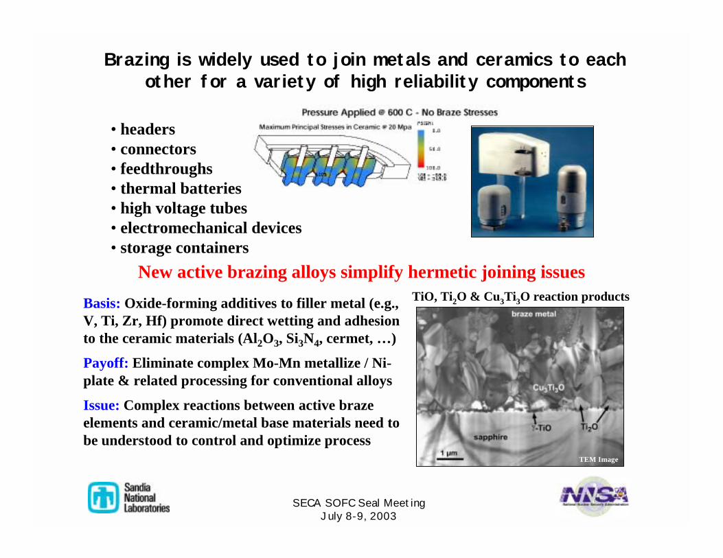
Brazing is widely used to join metals and ceramics to each other for a variety of high reliability components
New active brazing alloys simplify hermetic joining issues
Basis: Oxide-forming additives to filler metal (e.g., V, Ti, Zr, Hf) promote direct wetting and adhesion to the ceramic materials (Al2O3, Si3N4, cermet, …)
Payoff: Eliminate complex Mo-Mn metallize / Ni-plate & related processing for conventional alloys
Issue: Complex reactions between active braze elements and ceramic/metal base materials need to be understood to control and optimize process
• headers• connectors• feedthroughs• thermal batteries• high voltage tubes• electromechanical devices• storage containers
TEM ImageTEM Image
TiO, Ti2O & Cu3Ti3O reaction products
SECA SOFC Seal MeetingJuly 8-9, 2003
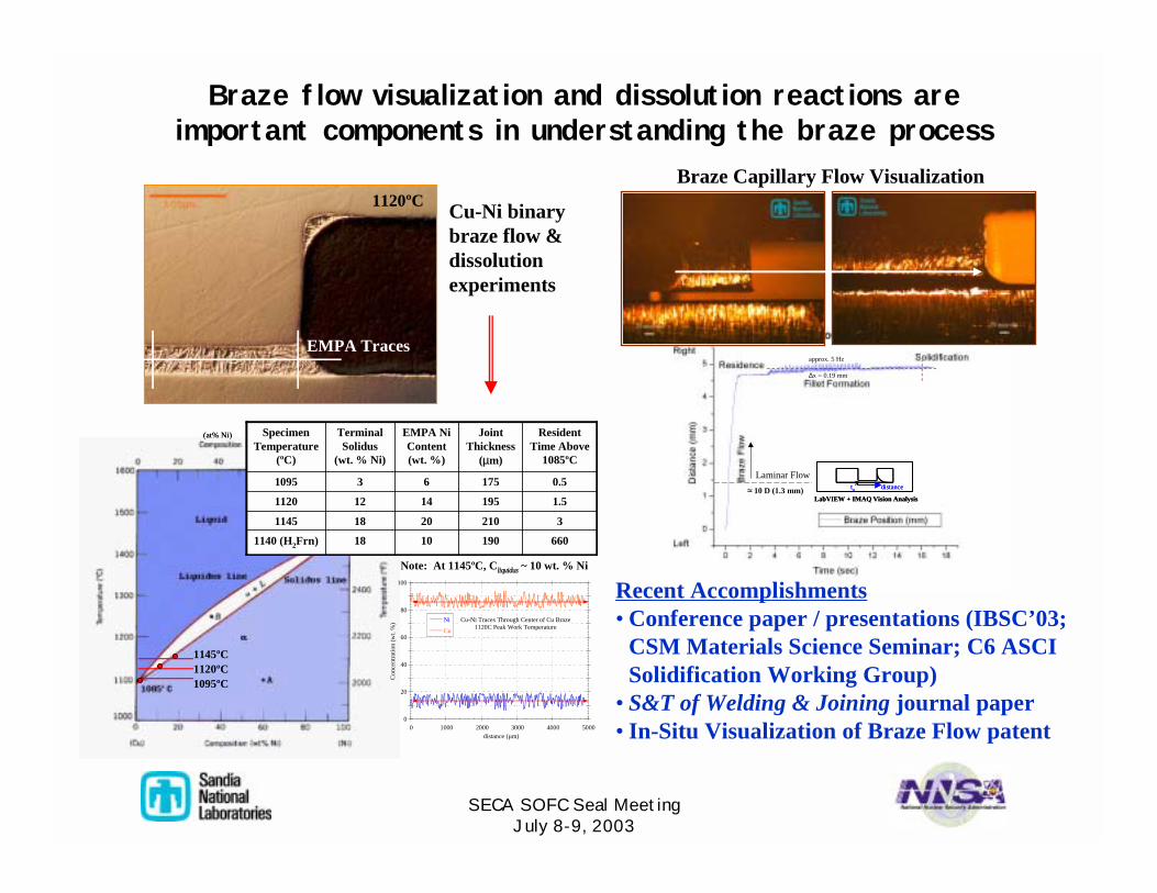
Braze flow visualization and dissolution reactions are important components in understanding the braze process
x distanceto
LabVIEW + IMAQ Vision Analysis
∆x = 0.19 mm
≈ 10 D (1.3 mm)
Laminar Flow
approx. 5 Hz
x distanceto
LabVIEW + IMAQ Vision Analysis
x distanceto
LabVIEW + IMAQ Vision Analysis
∆x = 0.19 mm
≈ 10 D (1.3 mm)
Laminar Flow
approx. 5 Hz
Recent Accomplishments• Conference paper / presentations (IBSC’03;
CSM Materials Science Seminar; C6 ASCI Solidification Working Group)
• S&T of Welding & Joining journal paper• In-Situ Visualization of Braze Flow patent
1095ºC
1145ºC1120ºC
(at% Ni)
1095ºC
1145ºC1120ºC
(at% Ni)
66019010181140 (H2Frn)
321020181145
1.519514121120
0.5175631095
ResidentTime Above
1085ºC
JointThickness
(µm)
EMPA Ni Content(wt. %)
Terminal Solidus
(wt. % Ni)
Specimen Temperature
(ºC)
66019010181140 (H2Frn)
321020181145
1.519514121120
0.5175631095
ResidentTime Above
1085ºC
JointThickness
(µm)
EMPA Ni Content(wt. %)
Terminal Solidus
(wt. % Ni)
Specimen Temperature
(ºC)
Note: At 1145ºC, Cliquidus ~ 10 wt. % Ni
0
20
40
60
80
100
0 1000 2000 3000 4000 5000
Ni
Cu
Con
cent
ratio
n (w
t. %
)
distance (µm)
Cu-Ni Traces Through Center of Cu Braze1120C Peak Work Temperature
1120ºC
EMPA Traces
1120ºC
EMPA Traces
Cu-Ni binary braze flow & dissolution experiments
Braze Capillary Flow Visualization
SECA SOFC Seal MeetingJuly 8-9, 2003
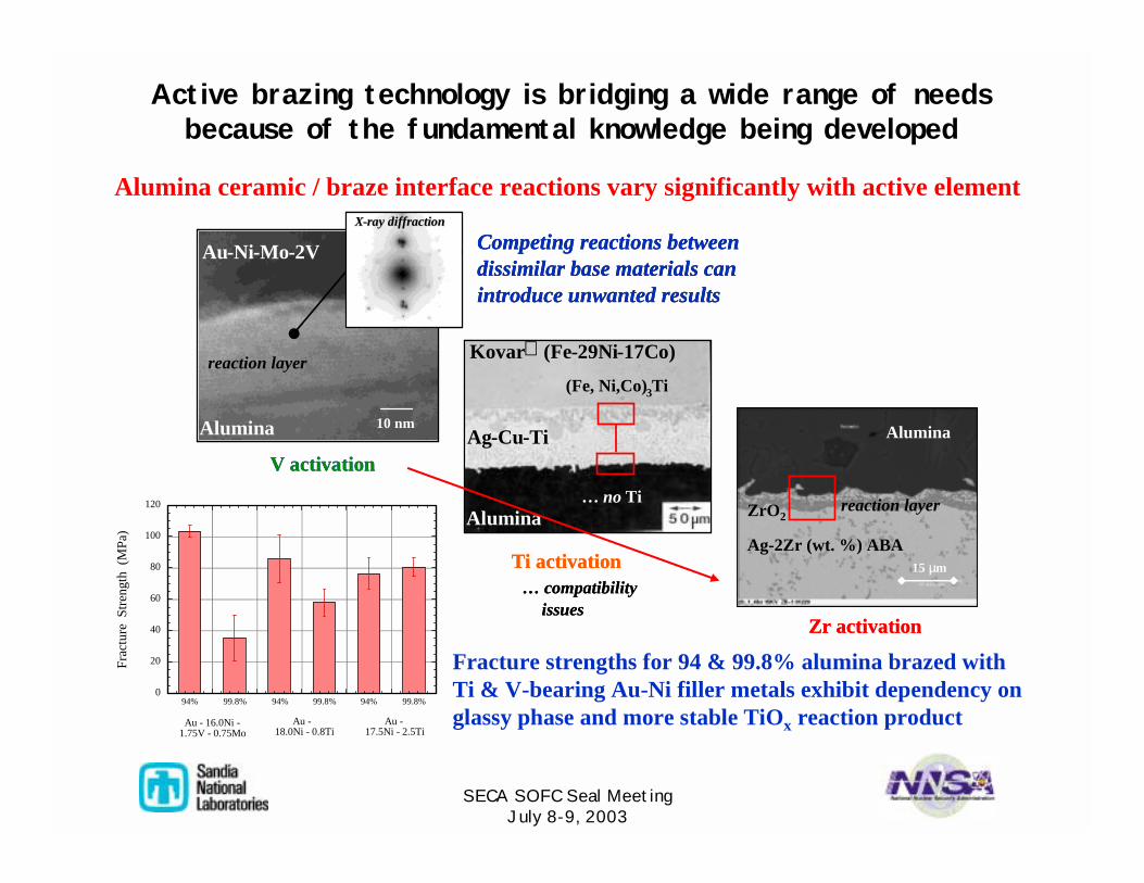
Active brazing technology is bridging a wide range of needs because of the fundamental knowledge being developed
0
20
40
60
80
100
120
Frac
ture
Stre
ngth
(M
Pa)
94% 94% 94%99.8% 99.8% 99.8%
Au - 16.0Ni -1.75V - 0.75Mo
Au - 18.0Ni - 0.8Ti
Au -17.5Ni - 2.5Ti
Alumina ceramic / braze interface reactions vary significantly with active element
Alumina
Au-Ni-Mo-2V
reaction layer
10 nm
XX--ray diffractionray diffraction
(Fe, Ni,Co)3Ti
… no TiAlumina
Kovar (Fe-29Ni-17Co)
Ag-Cu-Ti
Competing reactions between dissimilar base materials can introduce unwanted results
V activation
Ti activation… compatibility
issuesZr activation
Alumina
Au-Ni-Mo-2V
reaction layer
10 nm
XX--ray diffractionray diffraction
(Fe, Ni,Co)3Ti
… no TiAlumina
Kovar (Fe-29Ni-17Co)
Ag-Cu-Ti
Competing reactions between dissimilar base materials can introduce unwanted results
V activation
Ti activation… compatibility
issuesZr activation
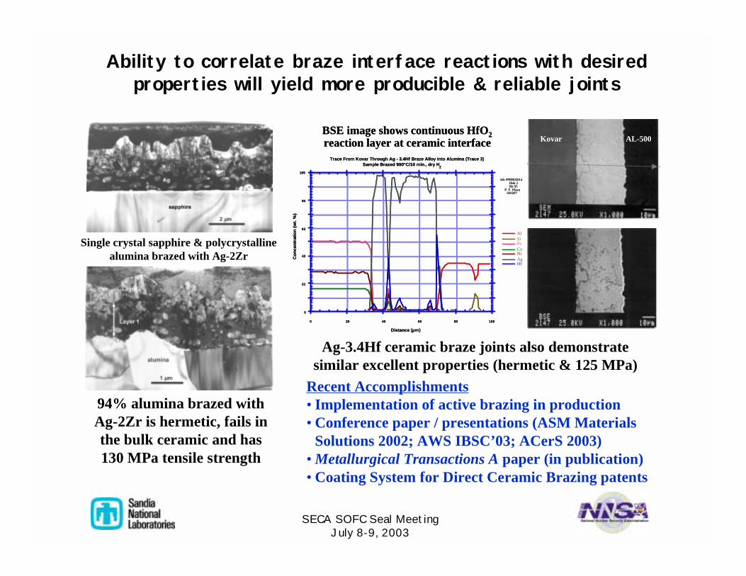
Fracture strengths for 94 & 99.8% alumina brazed with Ti & V-bearing Au-Ni filler metals exhibit dependency on glassy phase and more stable TiOx reaction product
Ag-2Zr (wt. %) ABA
reaction layer
Alumina
ZrO2
15 µm
SECA SOFC Seal MeetingJuly 8-9, 2003
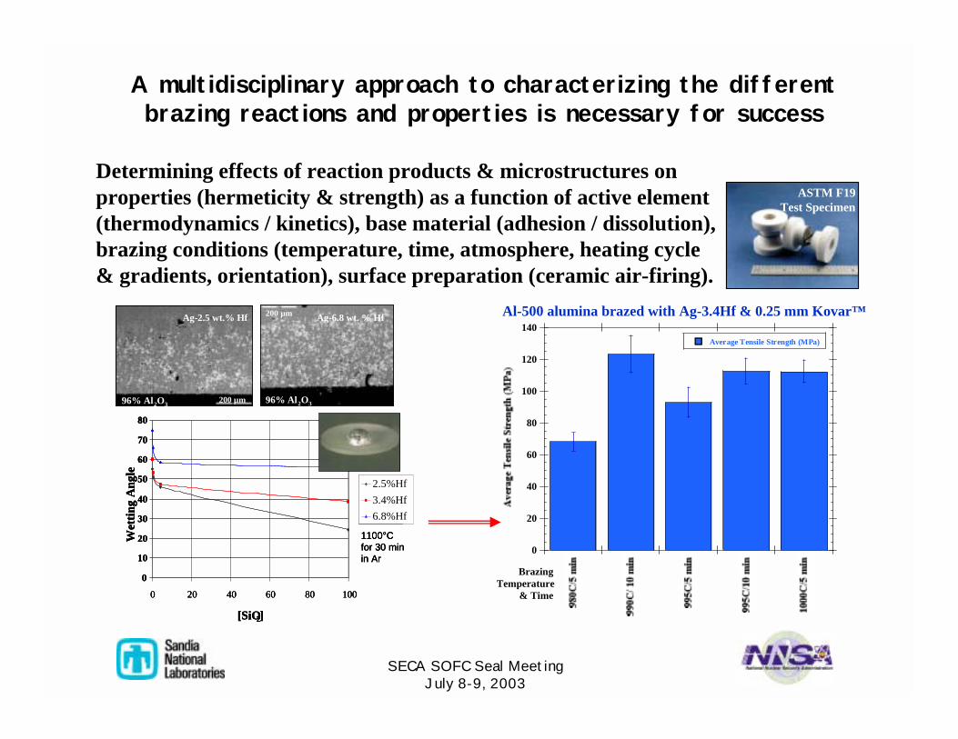
A multidisciplinary approach to characterizing the different brazing reactions and properties is necessary for success
0
20
40
60
80
100
120
140Average Tensile Strength (MPa)
BrazingTemperature
& Time
Determining effects of reaction products & microstructures on properties (hermeticity & strength) as a function of active element (thermodynamics / kinetics), base material (adhesion / dissolution), brazing conditions (temperature, time, atmosphere, heating cycle& gradients, orientation), surface preparation (ceramic air-firing).
Contact Angle vs. [SiO2]
0
10
20
30
40
50
60
70
80
0 20 40 60 80 100
[SiO2]
Wet
ting
Ang
le
2.5%Hf3.4%Hf6.8%Hf
1100°C for 30 min in Ar
Contact Angle vs. [SiO2]
0
10
20
30
40
50
60
70
80
0 20 40 60 80 100
[SiO2]
Wet
ting
Ang
le
2.5%Hf3.4%Hf6.8%Hf
Contact Angle vs. [SiO2]
1100°C for 30 min in Ar
0
10
20
30
40
50
60
70
80
0 20 40 60 80 100
[SiO2]
Wet
ting
Ang
le
2.5%Hf3.4%Hf6.8%Hf
1100°C for 30 min in Ar
200 µm
96% Al2O3
Ag-2.5 wt.% Hf
200 µm96% Al2O3
200 µm
96% Al2O3
200 µm
96% Al2O3
Ag-2.5 wt.% Hf
200 µm96% Al2O3
Ag-2.5 wt.% Hf
200 µm96% Al2O3
200 µm
96% Al2O3
Ag-2.5 wt.% Hf
200 µm96% Al2O3
200 µm
96% Al2O3
200 µm
96% Al2O3200 µm96% Al2O3
Ag-2.5 wt.% Hf
200 µm96% Al2O3
Ag-6.8 wt. % Hf
ASTM F19Test Specimen
ASTM F19Test Specimen
Al-500 alumina brazed with Ag-3.4Hf & 0.25 mm Kovar™
SECA SOFC Seal MeetingJuly 8-9, 2003
Ability to correlate braze interface reactions with desired properties will yield more producible & reliable joints
0
21
42
63
84
105
0 20 40 60 80 100
AlSiFeCoNiAgHf
Co
nce
ntr
atio
n (
wt.
%)
Distance (µm)
Job #PBR02014Disk 2file 95
P. F. Hlava020207
Trace From Kovar Through Ag - 3.4Hf Braze Alloy into Alumina (Trace 3)Sample Brazed 990°C/10 min., dry H