1.0 General Requirements ........................................................................................................ 6
1.1 Initial Due Diligence – Preliminary Capacity Availability....................................................... 6
1.1.1 Sanitary Sewer System and Basin Planning ................................................................... 7
1.2 Annexation into Metropolitan’s District ............................................................................... 7
1.3 City Annexation of Property Served by Metro ...................................................................... 7
1.3.1 Construction Approval of New Sanitary Sewer Collection Lines and Lateral Lines Following City Annexation....................................................................................................... 7
1.3.2 Permit Fees for City Annexed Property .......................................................................... 7
2.0 Approval and Acceptance Requirements ......................................................................... 8
2.1 Construction Document Requirements .............................................................................. 11
2.2 Review Process ................................................................................................................... 11
2.3 Construction Requirements ................................................................................................ 12
2.4 Metro Acceptance Requirements ....................................................................................... 13
* Please note this section (2.4 through 2.4.8) has changed to more accurately reflect the workflow* ................................................................................................................................. 13
2.4.1 Record Drawings .......................................................................................................... 14
2.4.2 Final Dedication ........................................................................................................... 15
1.0 General Requirements The following requirements establish the standards and procedures that apply to the design, construction, and connection to sanitary sewer collection systems located within the boundaries of the Metropolitan Sewer Subdistrict (Metro) or systems to be incorporated into Metro’s collection system.
Additional requirements may be required on a case‐by‐case basis when special conditions are presented.
1.1 Initial Due Diligence – Preliminary Capacity Availability Capacity analysis is required each time a new development proposes to connect to a Metro collector system and when the development connects to a collector system owned and operated by another public agency (i.e. city, special purpose district) that utilizes Metro sanitary sewer lines for transportation. A capacity analysis is required for all capacity requests.
The initial capacity analysis for a development is completed at the request of a property owner, realtor, developer, or engineer as a project is being conceived or in the early stages of a project. There is no charge for the initial capacity review. A fee of $100 shall be applied to any revised capacity requests by Metro. The person making the request is usually seeking documented assurance that capacity is available prior to proceeding with a project. Upon determination of capacity, Metro will provide approval or denial. If capacity is not available, Metro will discuss the restrictions within the collection system and pipeline upgrades that may be required. Capacity analysis requests will require a minimum of 5 business days to be completed.
Metro requires the following information for each new development to determine available capacity: Tax map number(s) identifying the area to be developed
The proposed average daily flow (ADF) as computed using SCDHEC’s unit contributory loadings (Appendix A, Standards for Wastewater Facility Construction, R.61‐67).
The proposed connection point(s) to Metro’s collection system (shown on a sewer map or referenced by manhole number).
Formal submittals shall be submitted on one of the following applicable forms:
ReWa’s “Public Main Extension Preliminary Capacity Request Form”, or
“Service Lateral Connection Capacity Request Form” (or most current). https://rewaonline.org/
7 Rev: 01/01/2021
Metro’s capacity analysis and sign‐off is required for project approval by other agencies within Greenville County. ReWa requires a Metro flow approval for all new developments prior to their approval of the project. Greenville County Planning Department requires Metro flow approval for all new subdivisions. Metro capacity approval is valid for one year, however; capacity is not guaranteed or reserved until development plans have been submitted and approved.
1.1.1 Sanitary Sewer System and Basin Planning Metro analyzes each proposed sanitary sewer system connection for planning of the overall basin. Sewer extensions, easements, and pipe sizing are reviewed to provide future sanitary sewer service to upstream parcels.
1.2 Annexation into Metropolitan’s District Parcels not located within Metro’s district, nor within the boundaries of a municipality or special purpose district, desiring to utilize Metro’s sanitary sewer system are encouraged to contact Metro for details of the annexation process.
1.3 City Annexation of Property Served by Metro When the city determines that a property is to be annexed into the city and that property is within Metro’s boundaries, the city shall provide Metro with written notice of the property being annexed. Metro will retain the first right of service if the property being annexed is connected to the Metro System. Metro and the city shall make a determination as to which entity shall provide sanitary sewer collection services to the property after annexation based upon the infrastructure in place and a sewer shed approach.
1.3.1 Construction Approval of New Sanitary Sewer Collection Lines and Lateral Lines Following City Annexation In the event that any annexed property served by Metro desires to construct new collection lines and/or lateral lines, Metro shall provide all permitting review and approval prior to the construction of such lines in accordance with these Sanitary Sewer Standards and Procedures. The city shall refer all persons to Metro for such review and approval. As the owner, Metro shall be solely responsible for the maintenance and operation of the Metro System.
1.3.2 Permit Fees for City Annexed Property When an annexed property desires to connect to the Metro System, the city shall require the permittee to provide a Metro permit to the city showing that all applicable fees have been paid to Metro prior to issuing a building permit for the project.
8 Rev: 01/01/2021
2.0 Approval and Acceptance Requirements To obtain approval for constructing, relocating, or modifying a sanitary sewer main, the applicant must submit a complete submittal package directly to Metro along with the Plan Submittal Checklist and the Project Information Form, both are located in Appendix C.
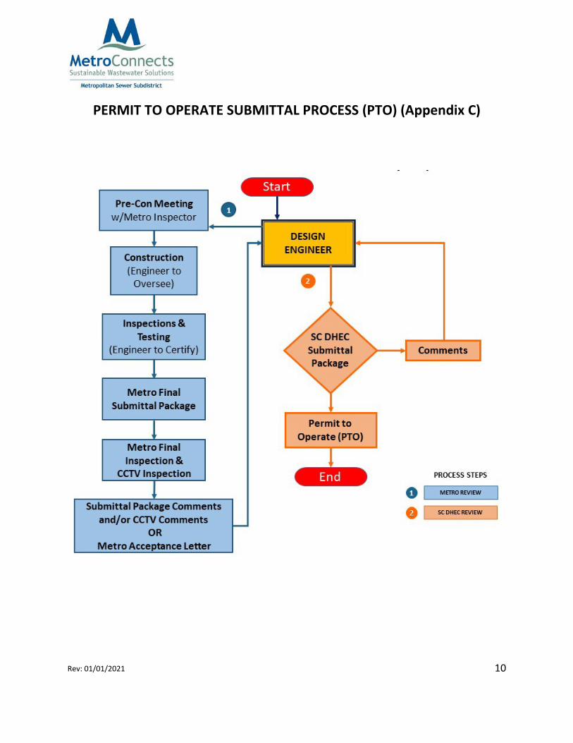
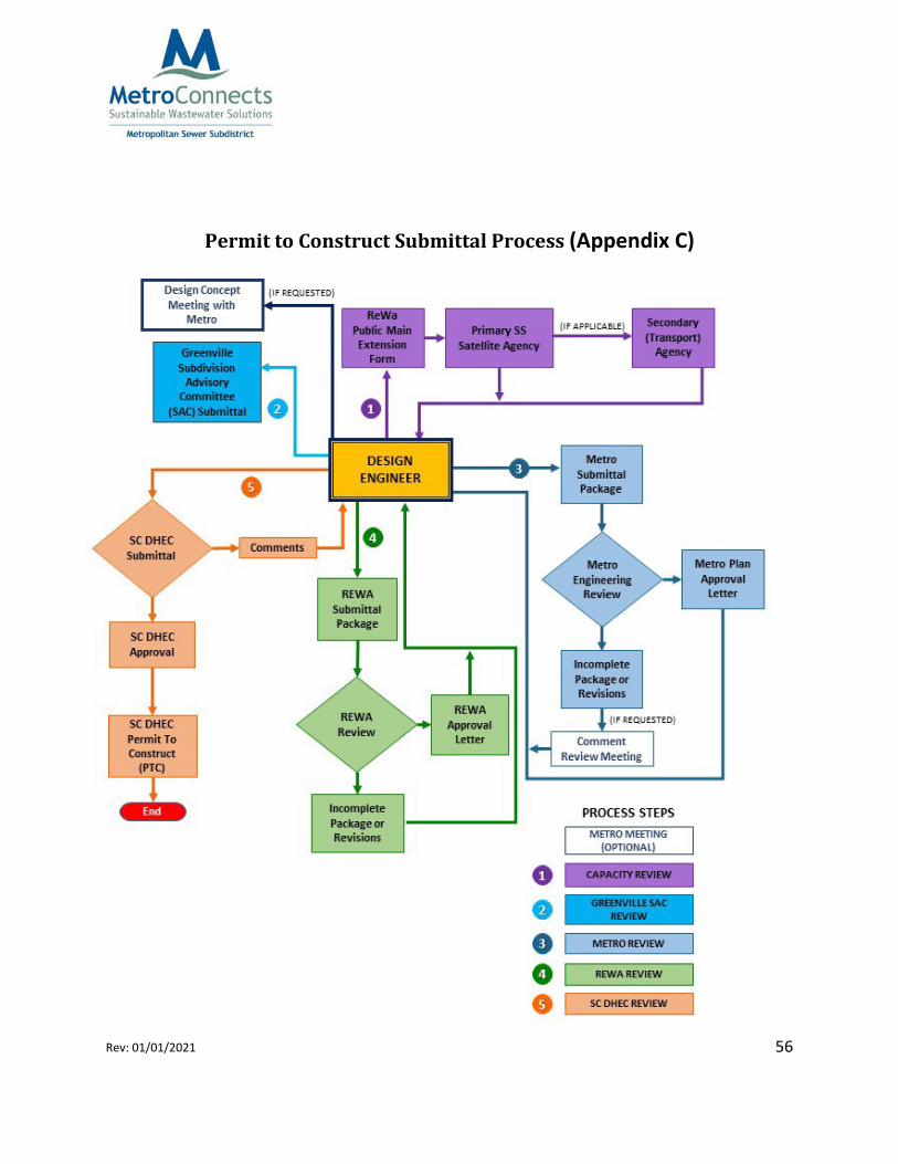
The overall permit submittal processes for obtaining approvals required for a SCDHEC Permit to Construct (PTC) and Permit to Operate (PTO) are shown in the flow charts titled Permit to Construct Submittal Process (PTC) and Permit to Operate Submittal Process (PTO).
Plan revisions or altered work differing in scope or nature from that authorized under the permit, are subject to Metro’s approval. Permittee shall promptly notify Metro of changed or unforeseen conditions, which may occur on site.
After approval, Metro may require an amended design at any time during any portion of the construction. Project transfer of ownership will require notification to Metro before construction continues. A Final Acceptance letter will not be issued until all construction has been approved by Metro.
Metro approval and/or acceptance is subject to cancellation due to: 1) noncompliance with permit provisions 2) noncompliance of Metro specifications 3) inability to access and maintain sewer infrastructure.
Please note that State law and regulations require submission of plans and specifications to obtain a written SCDHEC Permit to Construct (PTC) before a sanitary sewer system may be constructed or modified.
9 Rev: 01/01/2021
PERMIT TO CONSTRUCT SUBMITTAL PROCESS (PTC) (Appendix C)
10 Rev: 01/01/2021
PERMIT TO OPERATE SUBMITTAL PROCESS (PTO) (Appendix C)
11 Rev: 01/01/2021
2.1 Construction Document Requirements Plans and supporting documents must be prepared, signed, dated, and sealed by a Licensed South Carolina Professional Engineer. Construction plans must be in accordance with Metro’s standard details and specifications, review may be delayed if the submittal package is incomplete.
Construction drawings must include the name of the project, a vicinity map, graphic scale bar, north arrow, tax map number, survey datum and control information. An overall plan view must also be included displaying the following: lot lines, lot numbers, manholes, line segments, lateral locations, and road names. Construction drawings shall, at a minimum, include the proposed sanitary sewer main and manhole locations, rim elevations, invert elevations, drop elevations, pipe slope, pipe material, lot lines, lot numbers and proposed service connection locations. Plan submittals shall also contain grading plans. Plans must contain all pertinent notes and standard details. Metro Standard Details and Standard Technical Specifications are located in Appendix A and B respectively of this document.
The plans must show the proposed sanitary sewer main with plan and profile views on the same page. Both views must show all existing and proposed utility crossings. Utility crossings in existing easements or rights of way may require written permission from the appropriate utility provider approving the new sanitary sewer crossing as shown on the plans. Utilities (water, gas, storm drain) must be shown on both plan and profile views in grey scale and labeled as to type in order to indicate potential conflicts. Maximum plan view scale shall be 1:50.
It is the design engineer’s responsibility to identify potential temporary by‐pass systems on plans submitted to Metro. Temporary by‐pass systems will need to be coordinated with Metro. Any by‐pass of Metro’s system will need to be coordinated a minimum of 4 weeks prior to construction. A by‐pass plan will also need to be provided and at a minimum shall identify, but not be limited to, the existing wastewater flow, peak flow, type of bypass pump, auto‐dialer with contact information, duration of by‐pass, upstream system low point (Metro), SSO contingency plan, by‐pass layout (exhibit), redundancy, and any other necessary information. Metro may also require an agreement to be executed between the developer, contractor, and Metro.
2.2 Review Process The applicant must submit all items on the Plan Submittal Checklist directly to Metro. After a submittal is reviewed, comments will be available for pickup at Metro’s office. The engineer
12 Rev: 01/01/2021
must submit revisions directly to Metro. The revision box on the plans must be noted, signed and dated after each modification. Once Metro approves the submittal package, the engineer must include Metro’s approval letter to ReWa as part of the permitting process. The engineer should then refer to ReWa and SCDHEC for further information to complete and obtain a permit to construct (PTC) from SCDHEC.
2.3 Construction Requirements The Engineer shall be responsible for managing the construction of the sanitary sewer system and shall be the point of contact for Metro. The Engineer of Record is responsible for the oversight and documentation of construction inspections, all testing and final inspections to ensure all installation of the sanitary sewer system is in accordance with the approved plans and specifications.
2.3.1 Pre‐Construction Conference Construction is prohibited until the PTC is issued by SCDHEC and a mandatory pre‐construction meeting has been held with Metro’s inspector. The engineer must schedule Metro’s inspector at least 48 hours (two working days, not to include weekends or holidays) prior to the proposed mandatory pre‐construction meeting. Attendees shall include the contractor and any related sub‐contractors, owner/developer, and engineer. The pre‐construction meeting must occur prior to beginning installation. All applicable permits, shop drawings and recorded off site rights of ways shall be presented to Metro’s Inspector at the time of the pre‐construction meeting, if they have not been provided prior. See Appendix D for the Pre‐Construction Meeting Checklist.
Following the preconstruction meeting, the owner/developer agrees to the admission of properly authorized person’s at all reasonable hours for inspection. A copy of the SCDHEC PTC and one set of approved stamped construction drawings must be kept on site during construction and through final testing.
An additional pre‐construction meeting will be required in the event that construction ceases for more than 6 months or a new contractor becomes involved. Failure to comply may result in Metro’s non‐acceptance of the sanitary sewer system. All construction shall be in accordance with the construction drawings and specifications approved by Metro. The SCDHEC PTC does not constitute approval, temporary or otherwise, to place the system into operation.
The Contractor(s) shall be licensed in the State of South Carolina and have a WL (water and sewer contractor classification) and legally qualified under the provisions of the South Carolina’s Licensing Law (South Carolina Code of Laws Title 40, Chapter 11).
13 Rev: 01/01/2021
2.3.2 Changes During Construction The engineer shall be responsible for design changes that would cause any variance in construction from the design shown on the permitted “Issued for Construction” drawings. Any variances to the approved stamped construction drawings must be submitted by the permitting engineer for review and approval by Metro and SCDHEC, prior to construction of the modification. All revision dates shall be shown on the drawings. Once revised drawings have been approved, the engineer shall reissue revised drawings to the Contractor.
2.3.3 Engineering Inspectors Metro Engineering Inspectors shall NOT be responsible for the means, methods, techniques, sequences or procedures of construction selected by Contractor(s) or the safety precautions and programs incident to the work of Contractor(s). Metro Engineering Inspectors are on‐site to view progress, witness testing, and to observe specified materials being installed.
Metro Engineering inspectors typically develop daily field observation reports as part of their inspections. The reports may include, but not limited to, information such as weather conditions, onsite personnel (i.e. supervisor, electrician, competent person, etc.), onsite equipment, work observed, discussions that occurred in the field, etc.
2.3.4 Testing The engineer, or an employee under his direct supervision, shall witness and certify all testing for gravity systems, pump stations and force mains in accordance with the specifications and SCDHEC requirements.
2.4 Metro Acceptance Requirements
* Please note this section (2.4 through 2.4.8) has changed to more accurately reflect the workflow*
The Final Project Submittal Checklist (Appendix H) should be referred to for acceptance requirements.
A representative of the Engineering firm will be responsible for:
1. Scheduling of the final inspection with a Metro inspector 2. Providing a copy of the record drawings & Engineer’s final certification letter for the
final inspection 3. Drafting a punch list of any deficiencies
14 Rev: 01/01/2021
4. Scheduling repairs with the contractor 5. Notifying Metro’s inspector when repairs are complete
2.4.1 Record Drawings Upon completion of construction, record drawings shall be prepared by the engineer including the plan and profile. Plan and profile drawings shall show surveyed rim elevations, pipe invert elevations, line segment footage and slope, and shall accurately represent the as constructed sanitary sewer system. All Construction Plan information is required and shall be confirmed on the Record Drawings as constructed. Service lateral locations shall be shown on the sanitary sewer drawing and shall include lot numbers, road/street names, the distance from the downstream manhole to the service lateral, the length of the service lateral, and the depth of the service lateral at the connection point (see Figure 1). Any services which are DIP shall also be labeled as such. All record drawings shall be 24” x 36” in size and shall be noted and dated in the revision block. Record drawings must be signed and sealed by the Engineer of record.
(See Figure 1 on the next page)
After record drawings are reviewed, comments will be returned to the engineer if necessary for correction.
FIGURE 1 – Plan View Record Drawing Example
15 Rev: 01/01/2021
1. “SS” indicates the distance of the service lateral location from the downstream manhole.
2. “L” is the length of the service lateral from the main to the connection point.
3. “D” is the depth of the service lateral at the connection point.
4. Ductile iron pipe (DIP) services shall be noted on drawings.
2.4.2 Final Dedication The engineer shall provide to Metro the completed Final Project Submittal Checklist and Certification Letter Requirements, instructions, flow charts and legal documents are located in Appendix H. All items on the Final Project Submittal Checklist must be complete, all associated fees paid, and the sanitary sewer system dedicated to Metro, prior to the final acceptance letter being issued. Metro’s acceptance letter is a requirement by SCDHEC for the engineer to obtain the PTO.
2.4.3 Off‐site Easements If a proposed sanitary sewer system requires access onto an off‐site parcel; the developer will be responsible to obtain any and all off‐site sanitary sewer easements. The off‐site exhibit should be submitted to Metro for review before recording (see Off‐site exhibit Checklist).
The off‐site sanitary sewer exhibit shall be prepared by a Licensed South Carolina Professional Land Surveyor or Registered South Carolina Professional Engineer based on the Metro approved sanitary sewer alignment.). Metro’s plan approval letter will not be issued until a copy of the recorded off‐site Right of Way has been submitted.
The “Right of Way” document is located in Appendix H.
16 Rev: 01/01/2021
17 Rev: 01/01/2021
The checklist below serves as a guide for completing this process:
Off‐site Exhibit Checklist
8 1/2” X 11” Off-site Exhibit
Tax map numbers
Site address
Lot numbers
North arrow
Graphical scale bar
Existing sanitary lines and manholes (label manholes as defined by owner: e.g.,Metro, ReWa)
No metes and bounds associated with the sanitary sewer lines, easements, or manholes (including ties to property corners)
25’ sanitary sewer easement detail and note (Figure 3 in Appendix H)
No vertical data (rim or invert elevations)
Prepared by a Licensed South Carolina Professional Land Surveyor or Registered South Carolina Professional Engineer
Off-site exhibit title “Off-site sanitary sewer exhibit for: (developer or development) Not Metro Sewer
18 Rev: 01/01/2021
2.4.4 On‐site Easement Plats The sanitary sewer easement plat is required as part of the final dedication of the sewer system to Metro (see On‐site sewer easement plat checklist). The easement plat should be produced and submitted to Metro for review as soon as the sewer manholes and lines have been installed. Once the sanitary sewer easement plat has been approved by Metro Engineering the legal dedication process may begin (see flow chart on next page). NOTE: Failure to submit the sanitary sewer easement plat before project completion will result in closeout delays.
*The “Dedication and Conveyance” document is located in Appendix H.
Bearings and distances are required on the constructed sanitary sewer lines
SC state plane northing and eastings to be placed on manholes at both ends of each sewer run (center of manhole base, not center of ring and cover)
25’ sanitary sewer easement detail and note (Figure 3 in Appendix H)
No vertical data (rim or invert elevations)
Signed and stamped by a Licensed South Carolina Professional Land Surveyor
On-site easement plat title (Sanitary sewer easement plat for: (subdivision name with section and/or phase) Not Metro Sewer
21 Rev: 01/01/2021
2.4.5 Final Plats The following items will be required on the final development plat for recording:
Sewer line and manholes shown
Sewer Easement note and detail (Exhibit 3 in Appendix H)
Register of Deeds recording information for the Sanitary Sewer Easement Plat to be referenced
2.4.6 Development Covenants Covenants for the development shall contain the following statement:
“The Sanitary Sewer Rights of Ways for the development are defined in the Dedication and Conveyance of the Sanitary Sewer Line and Right of Way (easement) recorded in Deed Book , Page in the Office of the Register of Deeds for Greenville County and are shown on the recorded plat(s) referenced therein.”
2.4.7 Final Inspection The construction of the sanitary sewer system shall be complete prior to scheduling a final inspection. The engineer must schedule Metro’s inspector at least 48 hours (two working days, not to include weekends or holidays) prior to the proposed final inspection. All prior punch list items shall be completed. The pipelines and manholes shall be completely clean and free of gravel, dirt, and construction debris. All inverts shall be smooth with a uniform grade through the manhole and shall not hold water. All rights of way shall be cleared to a minimum width of 25 feet and shall be fine graded and grassed to allow vehicle access.
Following the final inspection, the engineer shall prepare the Final Inspection Punch List to provide to Metro’s inspector and the contractor. The engineer will notify Metro’s inspector when all punch list items are completed and schedule a follow up inspection. Upon satisfactory completion of the noted deficiencies, Metro will perform a CCTV inspection.
2.4.8 CCTV Inspection After the final inspection is complete and all deficiencies are corrected, Metro will perform a CCTV (closed circuit television) inspection of the sanitary sewer system and provide the CCTV Inspection Report (Appendix H) to the engineer. The engineer will be responsible for managing any required repairs, following the process specified in the report. Upon completion of deficiency corrections, the engineer shall return the executed CCTV Inspection Report to Metro for subsequent CCTV inspections. Upon acceptance of the inspection, Metro will forward a final
22 Rev: 01/01/2021
invoice to the engineer (see Fee Schedule – Appendix I). The CCTV inspections shall be performed by Metro in the order in which they are received.
2.5 Warranty The CONTRACTOR warrants to Metro that all materials and equipment furnished for the construction of the sanitary sewer system will be new unless otherwise specified, and that all work will be of good quality, free from faults and defects and in conformance with the approved plans, details, and standard specifications.
A warranty period of a minimum of one‐year is required for all new sanitary sewer systems and will begin once Metro issues a final acceptance letter. A longer warranty period may be required under special circumstances as determined by Metro. The contractor shall, promptly and without charge to Metro, repair, replace, or otherwise remedy such defects that may be discovered or develop at any time within the warranty period to the full and complete satisfaction of Metro. The warranty shall be extended automatically to cover all repaired and replacement materials and labor provided or performed under the warranty for a period of one year from the date of such repair or replacement.
3.0 Gravity Sewer Design Design of all sanitary sewer systems that are to be dedicated to Metro shall be performed by a Professional Engineer registered in the State of South Carolina. All designs shall be in accordance with the Design and Specifications Manual, South Carolina Department of Health and Environmental Control (SCDHEC) Regulation 61‐67, and the Ten State Recommended Standards for Wastewater Facilities (latest edition). Where information presented herein conflicts or overlaps with a governing regulation, deed, or plat restriction, the more stringent restriction shall prevail.
Horizontal survey datum control shall be based upon, and referenced to, South Carolina State Plane, NAD83 HARN, International Feet coordinates. Vertical survey datum control shall be based upon, and referenced to, the North American Vertical Datum of 1988 (NAVD 88). Electronic drawings submitted to Metro shall be in the correct projection, coordinate system, datum, and units.
Sanitary sewers are designed for the collection and transmission of wastewater. Downspouts, foundation drains, yard drains, area drains, basement drains, hazardous waste materials, and sump discharges for other than sanitary waste shall not be connected to the facilities of Metro.
23 Rev: 01/01/2021
The safety and protection of public and private water supplies is vital. There shall be no connection between any public or private potable water supply system and any sanitary sewer or appurtenance thereto which would permit the passage of any sewage or polluted water into the potable water supply.
3.1 System Sizing New sanitary sewer mains shall be a minimum of eight inches in diameter. Average daily flows shall be calculated using SCDHEC’s Unit Contributory Loadings. Peak flows shall be calculated by multiplying the average daily flow by a peaking factor based on the following formula. In no case shall the peaking factor be less than 2.5.
18 + Peak Factor =
4 , where P = population in thousands
Refer to “Recommended Standards for Wastewater Facilities,” latest edition
Pipes shall not exceed the following maximum allowable flow depths:
TABLE 1
Pipe Diameter (inches)
Maximum Percent Full at Peak Flow
8 50 10 50 12 60 14 65 15 70 16 70
3.2 Sanitary Sewer Upsizing and Extension Sanitary sewer mains shall be designed to serve the entire drainage basin. If there is the potential for service to be extended beyond the proposed development, Metro will prepare flow calculations for the basin. Flow calculations shall include projections of future flows for upstream areas that drain into the site based on zoning and current development trends. Upsizing of the proposed sanitary sewer system may be required by Metro. Upon request, Metro may reimburse the material cost difference of the upgrade subject to Commission approval.
+
24 Rev: 01/01/2021
Similarly, provisions shall be made for future extensions at proposed locations as determined by Metro. In the case where no upstream extensions are reasonable or likely, sanitary sewer systems may be terminated at a point acceptable to Metro.
3.3 Minimum Slope and Velocity Gravity sewers shall be designed with uniform slope between manholes. Calculations for velocity will be based on Manning's formula using an "n" value of 0.013. In cul‐de‐sacs or other low flow situations, the slope from the starter manhole shall be a minimum of 1% on an 8” system.
A minimum velocity of 2.0 feet per second is required. In no case shall the slope of a pipe fall below the minimum values listed in Table 2 below. Pipe sizes shall not be increased arbitrarily to take advantage of a flatter grade.
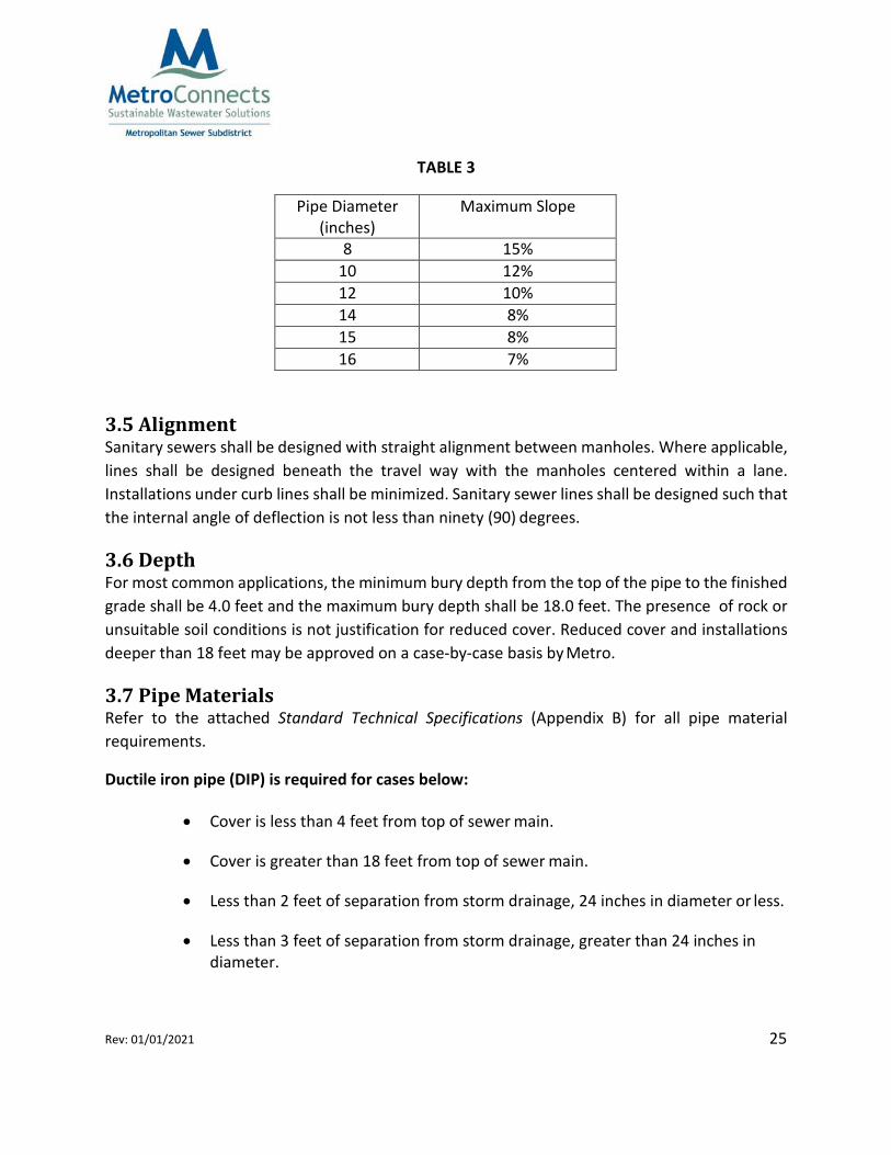
3.4 Maximum Slope and Velocity Drop manholes may be used when required to reduce steep slopes and high velocities. Where permitted, slopes exceeding Table 3 values , may be required to include additional appurtenances or materials. Examples include but are not limited to restrained joint pipe, restrained fittings, pipe material, inverts and/or special linings toprovide protection against internal erosion in conformance with ASTM and/or American Water Works Association (AWWA) specifications.
25 Rev: 01/01/2021
TABLE 3
Pipe Diameter (inches)
Maximum Slope
8 15% 10 12% 12 10% 14 8% 15 8% 16 7%
3.5 Alignment Sanitary sewers shall be designed with straight alignment between manholes. Where applicable, lines shall be designed beneath the travel way with the manholes centered within a lane. Installations under curb lines shall be minimized. Sanitary sewer lines shall be designed such that the internal angle of deflection is not less than ninety (90) degrees.
3.6 Depth For most common applications, the minimum bury depth from the top of the pipe to the finished grade shall be 4.0 feet and the maximum bury depth shall be 18.0 feet. The presence of rock or unsuitable soil conditions is not justification for reduced cover. Reduced cover and installations deeper than 18 feet may be approved on a case‐by‐case basis by Metro.
3.7 Pipe Materials Refer to the attached Standard Technical Specifications (Appendix B) for all pipe material requirements.
Ductile iron pipe (DIP) is required for cases below:
• Cover is less than 4 feet from top of sewer main.
• Cover is greater than 18 feet from top of sewer main.
• Less than 2 feet of separation from storm drainage, 24 inches in diameter or less.
• Less than 3 feet of separation from storm drainage, greater than 24 inches in diameter.
26 Rev: 01/01/2021
ANSI/AWWA C900 may also be used in depths equal to or exceeding 18 feet. In approved cases, PVC pipe meeting the requirements of AWWA C900 may be used in place of Ductile Iron Pipe. DIP or C900 may be required in areas where superimposed loading occurs due to other utilities or structures.
3.8 Horizontal and Vertical Separation All separation requirements are measured from the nearest outside edge of the sewer pipe to the nearest outside edge of any other utility.. Sewer mains shall have a minimum 18 inch separation from water mains. Sewer lines shall be at least 10 feet horizontally from potable water mains, unless otherwise permitted by Metro. Should local conditions prevent a horizontal separation of 10 feet, the sewer main must be in a separate trench where the elevation of the top of the sewer is at least 18 inches below the bottom of the water main.
A minimum of 24 inch separation for all other underground utility systems, both horizontally and vertically, shall be maintained. Refer to details if 24 inch separation can not be achieved. No utility shall be within 4 feet of a sanitary sewer manhole.
Prior approval from Metro must be obtained before a sanitary sewer main is permitted to cross a water main. When local conditions necessitate that a sewer main and potable water main cross, all reasonable efforts must be made for the sewer line to cross under the water main. New sanitary sewer crossing water mains shall be designed to provide a minimum vertical separation of 18 inches. The crossing shall be arranged so that the sewer joints will be equidistant and as far as possible from the water main joints.
When unique and exceptional conditions exist such that a minimum 18‐inch vertical clearance cannot be maintained between a sanitary sewer main and any other underground utility crossing, the following conditions must be addressed on the plans:
1. The crossing shall have adequate structural support to prevent damage to the main.
2. The sewer main shall be a slip type or mechanical joint pipe complying with
ANSI/AWWA C900 or ANSI/AWWA C600 (D.I.P), public water supply standards. This section of the sewer line shall be pressure tested in accordance with Metro specifications.
When a new utility installation crosses an existing sewer line not meeting the minimum clearances specified above, a section of the existing sewer line must be replaced with pipe meeting conditions 1 and 2 above for a distance of at least 18 feet centered under the crossing utility, or as directed by Metro. In addition to the requirements specified above, a water main shall not be allowed to pass through or come into contact with a sewer manhole.
27 Rev: 01/01/2021
3.9 Steel Pipe Casing When dry boring and jacking is required for the construction of sanitary sewer lines; or when a steel casing and carrier pipe system is used for longer aerial spans, installation shall be in conformance with the latest Metro Standard Details and Standard Technical Specifications.
Steel casing pipe shall be laid to the appropriate line and grade, as designed and permitted, working in the upstream direction. At least one end of the encasement shall be a minimum of 25’ from the closest manhole.
When the casing pipe is installed without the benefit of protective coating or said casing is not cathodically protected, the wall thickness shall be increased to the next higher standard thickness as approved by Metro.
3.10 Relationship to Water Bodies Sanitary sewer lines shall not be located in or under ponds, pond embankments, lakes, storm water detention ponds, or within dams or any other structures that hold water on a permanent or temporary basis. Sewers crossings must meet all associated state and federal permitting requirements. Prior to issuance of Metro’s approval letter, the engineer shall deliver all required permits and a sealed letter that all required permits have been obtained, or are not required, from all relevant permitting agencies including Local Floodplain Development, US Army Corps Wetlands, State 401 Water Quality, etc.
Aerial and underground stream crossings will be approved by Metro on a case‐by‐case basis. Sewer systems shall be designed to minimize the number of stream crossings. Sewers crossing streams must be designed to have a minimum impact on the stream cross section and ecosystem and must cross the stream as nearly perpendicular to the stream flow as possible. Metro will not allow inverted siphons.
When proposed aerials are to cross areas of floodplain, it is recommended to present a preliminary plan to the County floodplain administration before submitting to Metro.
3.10.1 Aerial Crossings Detail SS‐4.0 depicts Metro requirements, information to be shown on design drawings, and information to be considered as part of the design of an aerial crossing.
It is the responsibility of the engineer to account for the design of piers, pier footings, pipe spans, pipe span connections, and the associated geotechnical and structural analysis. The information provided by metro is for information only and does not relieve the design engineer
28 Rev: 01/01/2021
from the responsibility and obligation to consider all issues related to the proper design of all structures and systems and compliance with all applicable regulations and standards.
If an aerial crossing is necessary, all non‐mechanical pipe joints shall be pier supported. The pier supports shall be designed to prevent frost heave, overturning, and settlement. The impact of floodwaters and debris shall also be considered in the pier and pipe design. The pipe bottom shall be a minimum of one (1) foot above the 100‐year flood elevation or shall be placed beneath the stream as an underground crossing. Designs that do not meet this criteria will be evaluated on a case by case basis.
It is Metro’s intent to locate piers outside the regulatory floodway and outside the stream top of bank. Coordinate with Metro if no regulatory floodway exists or the regulatory floodway width is significant. Piers proposed to be placed within the regulatory floodway or within the stream top of bank will be evaluated on a case by case basis. All ditch, creek, stream, and river (aerial and underground) crossings shall be ductile iron pipe (DIP) coated with Tnemec 431 from manhole to manhole and the associated channel banks shall be stabilized. Encasement pipes for underground crossings shall be steel. Alternate pipe materials and stream bank stabilization may be reviewed on a case by case basis.
Rough staking of each proposed aerial and underground stream crossing is required for Metro to perform a site visit and visually confirm the location prior to approval. Hydrology and hydraulic calculations may be required on a case by case basis.
The following note (with PE seal and signature immediately beneath) are required on each drawing with an aerial crossing:
I confirm that the components of the aerial crossing including, but not limited to, piers, pier footings, pipe spans, and pipe span connections have been designed, and the required geotechnical and structural analysis of each component have been performed, by me or under my direction.
3.10.2 Underground Crossings If an underground crossing is necessary across a US Army Corps regulated stream, it shall be installed either by open cut or by jack and bore method. An encasement and carrier pipe may be required by Metro. The encasement pipe shall extend a minimum of 20 feet on both sides of the stream channel measured from the top of bank, or as directed by Metro. The top of all encasement pipes shall be at a sufficient depth below the natural bottom of the stream bed to protect the sewer line crossing. In general, the following cover requirements must be met; 1)
29 Rev: 01/01/2021
One foot of cover where the sewer is in rock, and 2) four feet of cover in other material. In some cases, more than four feet of cover may be required.
3.11 Manholes Manholes must be installed at the end of each gravity sewer main line; at all changes in line size, slope, or alignment; and at all intersections. Additionally, manholes must be installed at intervals not greater than 350 feet for all sewers 18 inches and smaller. Where applicable, manholes shall be placed within the center of the travel lane.
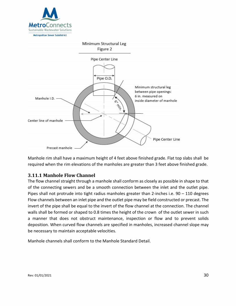
For most common applications, the minimum interior diameter of gravity sewer manholes shall be 48 inches for manholes that are less than 14 feet deep and 60 inches for manholes 14 feet deep and greater, measured from the lowest invert of the manhole to the top of the cover. In no case shall manhole depths be less than 5 feet deep. Any manholes placed in fill areas must utilize an extended base section (see detail Appendix A). Additional compaction testing may be required for manholes placed in fill areas. No more than four (4) connections (including laterals and mains) are permitted to any one manhole without prior approval of Metro. There shall be a minimum of 6‐inches of structure leg between pipe connections (see Figure 2). Minimum horizontal angle between all incoming (invert in) and outgoing (invert out) pipes shall be 90 degrees. Where a new sewer line ties to an existing brick manhole, the manhole must be completely replaced with a precast reinforced concrete manhole meeting Metro specification.
30 Rev: 01/01/2021
Manhole rim shall have a maximum height of 4 feet above finished grade. Flat top slabs shall be required when the rim elevations of the manholes are greater than 3 feet above finished grade.
3.11.1 Manhole Flow Channel The flow channel straight through a manhole shall conform as closely as possible in shape to that of the connecting sewers and be a smooth connection between the inlet and the outlet pipe. Pipes shall not protrude into tight radius manholes greater than 2‐inches i.e. 90 – 110 degrees Flow channels between an inlet pipe and the outlet pipe may be field constructed or precast. The invert of the pipe shall be equal to the invert of the flow channel at the connection. The channel walls shall be formed or shaped to 0.8 times the height of the crown of the outlet sewer in such a manner that does not obstruct maintenance, inspection or flow and to prevent solids deposition. When curved flow channels are specified in manholes, increased channel slope may be necessary to maintain acceptable velocities.
Manhole channels shall conform to the Manhole Standard Detail.
31 Rev: 01/01/2021
A bench shall be provided on each side of the flow channel. The bench shall be sloped no less than 1‐inch per foot. No lateral, service connection, or drop manhole pipe shall discharge onto the surface of the bench.
Through design and installation, careful consideration must be taken to compensate for the head losses occurring through the flow channel between all manhole inlets and outlets. Manholes shall have a minimum 0.2 foot drop in elevation from the lowest inlet invert to the invert of the outlet. A 0.1‐foot drop may be considered under special circumstances at the discretion of Metro. Where a new sewer connects to an existing main and a new manhole is required, there shall be a minimum 0.3 foot drop in elevation from the invert of the new inlet to the outlet pipe invert. All manholes shall have a maximum 0.3 foot drop in elevation through the manholes. All changes of direction, size or shape of sewers shall be made by smooth transitions in the flow channel to minimize head loss in manholes. Where a smaller sewer transitions to a larger one through a manhole, the crown elevation of the two pipes must match.
3.11.2 Drop Manholes The use of drop manholes shall be minimized. Metro shall approve the use of drop manholes only when it cannot be avoided. The minimum drop, measured from the invert of the incoming pipe to the manhole invert, shall be no less than 5 feet. Drops of less than 5 feet may be allowed on a case by case basis with approval from Metro. No connection to the manhole shall be made between 12 inches and 5 feet above the manhole invert without prior approval from Metro.
Inside drop manholes must be constructed in conformance with the latest Metro Standard Details and Standard Technical Specifications. Inside drops are preferred. A Reliner Force Line Hood is required if the slope of sewer main is greater than 5% or directed by Metro per construction plans. Outside drops may be allowed on a case by case basis with approval from Metro.
3.11.3 Doghouse Manholes Doghouse manholes will be approved on a case by case basis.
3.11.4 Water‐tight Manhole Ring and Covers Infiltration to and exfiltration from the sanitary sewer system must be minimized to the greatest extent possible. Watertight manhole covers are to be used wherever the manhole tops may be flooded by street runoff or high water. All manholes and other above ground access
32 Rev: 01/01/2021
points located less than one foot above the 100 year Base Flood Elevation (BFE) shall be watertight.
When working in wet areas, care shall be taken to ensure water tightness of structures per ASTM C443. The engineer should refer to specification section 02240 for dewatering requirements.
3.11.5 Corrosion Protection for Manholes Where corrosive conditions due to septicity or other causes are anticipated, such as at a force main discharge, corrosion protection on the interior of the manholes is required. In such case, see approved materials detail. The interior of manholes for a distance not less than 1,000 linear feet downstream of the corrosive source must also be coated with acid resistant material.
3.12 Service Laterals Service lateral design shall include coordination with other utilities, proposed structure finished floor elevations (basement), lot grades, etc. Design shall be in conformance with the standard sewer service lateral detail(s) and shall maintain true line and grade ‐ 1% minimum. (see details in Appendix A). Additional laterals will not be allowed to be installed on new systems which have already been installed without permit approval from Metro.
Ductile iron pipe (DIP) shall be used for service laterals when the depth of cover is less than 4 feet, when located within 24 inches of storm drain structures, or where point superimposed loading may occur due to other utilities or structures. All DIP laterals to be installed shall be shown on construction plans and as‐built drawings.
Service laterals are encouraged to be tied into manholes. Service lines connected to the gravity main must be a minimum of 90 degrees in relation to the downstream section of the main. The invert of the lateral shall be called out on the plans and shall be constructed per the Standard Details (see Appendix A).
In subdivisions, the service lateral shall be installed a minimum of 5 feet upstream of the lowest property corner fronting the proposed sewer and stub outs shall be in unpaved areas and marked.
4.0 Pump Station and Force Main Design The owner/developer and engineer must coordinate a pre‐design conference for all projects requesting the use of pump stations and force mains. Metro has determined that, in appropriate circumstances, it may own and operate sanitary sewer pump stations, which constitute a part of its sewer collector system to carry out its
33 Rev: 01/01/2021
functions and serve constituents within its boundaries. Metro may accept sanitary sewer pump stations, on a case‐by‐case basis, subject to the provisions of the Pump Station Policy (Appendix E).
Pump stations should typically be regional in nature. Pump stations and force mains shall be designed and installed in accordance with sound engineering practice and must adhere to South Carolina Department of Health and Environmental Control Regulation 61‐67, Ten State Recommended Standards for Wastewater Facilities (latest edition), and Renewable Water Resources (ReWa) regulations. Third party peer review and inspection may be required.
4.1 Pump Stations It is Metro’s policy to minimize the need for wastewater pumping stations, or simply pump stations, and to limit their construction and use within the sanitary sewer system. The basis for this general policy is that pump stations can cause disproportionate expense in order to provide service to a limited customer base. The operation and maintenance costs and time for maintaining the pump stations represents a continuing cost and maintenance issue that may stretch available resources and ultimately result in further cost increases, and failure to address issues of pump stations would pose significant environmental risks. Please refer to the Pump Station Policy (Appendix E) for further explanation on the factors that will be considered in Metro’s review as it relates to the potential transfer of ownership of wastewater pumping stations.
However, it is recognized, that there are situations where pump stations are required because gravity service is not available or possible. Metro will only consider approval of pump stations when installation of gravity sewer mains is not possible. The layouts of the pump station and force mains shall match details shown in Appendix A – Standard Details. The pump station wet well, and dry well shall be ventilated, excluding the valve pit. The vent shall be a screen inverted “I” tube and be constructed with a weather durable material. The Applicant’s Engineer shall be responsible for incorporating odor control into their pump station design such that acceptable levels are determined by Metro are achieved. If it is determined that odor control measures are required, the Applicant’s Engineer shall adhere to the following guidelines:
1) Odor control measures via mechanical or chemical treatment may be allowed. Any
odor control methods and technologies must be approved by Metro before it can be implemented.
34 Rev: 01/01/2021
2) The Applicant’s Engineer shall predict hydrogen sulfide levels at force main discharges and incorporate odor control facilities as deemed necessary and/or required by Metro.
The pump station shall be sized to convey the peak hourly design flow, with the largest pump out of service. The design must consider the immediate peak daily design flow and the peak flow at basin build‐out, as directed by Metro. Both peak flows must be accommodated by the design. Future additions or modifications to the station may be required to handle the range of flows in order to maintain force main velocities and to minimize hydrogen sulfide corrosion. To meet these criteria, impellers may have to be trimmed initially and then replaced with full‐size impellers, or Variable Frequency Drives (VFD) may be installed, when flows increase.
Wet wells shall meet the following design criteria:
1) Wet wells for pump stations shall be made of standard precast concrete or polymer
concrete, with a minimum 8 feet in diameter, unless otherwise approved.
2) All precast concrete wet wells shall be coated as specified in Section 04301 – Corrosion Protection for Concrete Wastewater Structures in Appendix B – Standard Technical Specifications.
3) Steps shall not be provided in wet wells.
4) Wet wells shall be sized to minimize pump start/stop cycles. Metro may require that
the wet well volume and control systems are modified in order to minimize the pump cycles per hour.
5) Total wet well storage (i.e. wet well storage + pipe storage + manhole storage) must
exceed the volume in force main from wet well to global high point along force main.
6) The buoyant (uplift) force factor of safety (F.S.) must meet or exceed 2.0. Refer to the equation below:
F.S.= ≥2.0
35 Rev: 01/01/2021
7) Pump station manufacturer shall determine minimum submergence of pumps or suction bell (i.e. Pumps off elevation) in wet well.
8) At a minimum, the wet well and control system shall be designed such that the lead
pump does not turn off until the water surface elevation (WSE) if 4 feet above the pump impellor or suction bell.
The Applicant’s Engineer shall submit detailed design calculations as part of the Plan Submittal Package which demonstrate how the wet well was sized and how the pumps will operate over the full range of flows. Certification from the pump manufacturer shall be submitted with the design calculations to demonstrate that the motor and control circuit will minimize the number of cycles per hour.
4.2 Force Mains The pump station and force main piping shall be designed to have the adequate capacity to serve the proposed and future developments upstream of the proposed pump station. Where it is necessary for wastewater force mains to cross surface water or wetlands, the Applicant’s Engineer shall include a proposed method of construction with their submittal package for review and approval prior to submitting plans for permitting. Metro does not allow aerial force main crossings. Examples of aerial crossings include, but are not limited to, force mains constructed on piers or pilings, and force mains attached to structures such as roadways, bridges or piers.
All force mains designed to connect to the Metro sewer system shall meet the following design criteria requirements:
1) Velocities in the force main shall be at least 2 feet per second (fps) and not greater than
5 fps.
All force mains shall be a minimum of 4 inches in diameter.
Minimum bury depth from top of pipe to finished grade shall be 4 feet, including SC DOT R/W.
Refer to Section 04531 Sanitary Sewer Force Mains Appendix B – Standard Technical Specifications for all required materials of construction and standards for piping, fittings, joints and associated appurtenances.
Air release valves and air/vacuum release valves shall be installed at the following locations:
• system high points,
• at significant changes in grade,
• and/or in locations requested by Metro.
In some situations, Metro may require that air release valves (ARVs) are in valve vaults at pump stations. If deemed necessary, this requirement shall be communicated to the Applicant’s Engineer in Metro’s comments to the submittal package. Refer to the appropriate ARV detail in Appendix A – Standard Details.
The ARVs shall be sized to thoroughly exhaust all trapped air and prevent a destructive vacuum from forming. Refer to 04005 ‐ Air‐Vacuum Valves for Wastewater Service in Appendix B – Standard Technical Specifications for acceptable materials and construction procedures for air release valves.
PVC piping shall be the only type of piping permissible at all local and global high points along the force main alignment. All piping within 5 feet vertically of the high point shall be PVC. At the global high point of the force main, the PVC piping is only required for the upstream piping within 2 feet vertically of the high point.
In certain situations, all or portions of the force main downstream of the global high point may experience a “flow away” condition in which the hydraulic grade line (HGL) falls below the pipe elevation, thus creating partially full pipe flow. In this situation, air will be introduced into the force main and create a condition for hydrogen sulfide corrosion. Therefore, PVC pipe shall be used in sections where the “flow away” condition may occur. In general, changes in pipe material shall be minimized. Refer to Figure 6‐1 for illustration:
Figure 4‐1: Pipe Material for Force Main at High Points
36 Rev: 01/01/2021
37 Rev: 01/01/2021
Air release valve valults shall be made of polymer concrete or coated with an epoxy coating that matches what is required for wet wells and manholes. Refer to Section 04301 – Corrosion Protection for Concrete Wastewater Structures in Appendix B – Standard Technical Specifications.
Plug isolation valves shall be located on upstream and downstream end of the air release valve. A plug isolation valve is only required to be located on the downstream end of the air release if there are no high points in between pump station and air release valve. If the air release valve is located within a valve vault, the plug valves shall be located outside of the vault. Refer to the appropriate air release valve detail in Appendix B – Standard Details.
All force mains entering receiving manholes shall be designed to match details in Appendix B – Standard Details. Refer to ReWa details for all forcemains entering a ReWa manhole.
Refer to Section 3.0 – Gravity Sewer Design for further instruction on the appropriate peaking factor to use for capacity design.
A connection to a new or existing force main (manifold) is site‐specific and subject to multiple design options. Connections may include cutting in a new fitting or connecting with a tapping sleeve – stainless steel. At a minimum, force main will include a plug valve for isolation of the secondary (new) force main. Exact configuration of connection will be advised by Metro on a case‐ by‐case basis.
New or existing receiving manholes (manholes where the force main discharges into the gravity sewer) must follow the criteria below:
1) Force main connections to manholes shall be made in accordance with the Detail PS‐
12.0, Typical Force Main Discharge to Existing Receiving Manhole in Appendix A – Standard Details unless otherwise approved by Metro.
2) New receiving manholes shall be polymer concrete or lined in accordance with Sections
04301 and 04305 in Appendix B – Standard Technical Specifications.
3) Existing receiving manholes shall be coated in accordance with Section 04301 ‐ Corrosion Protection for Concrete Wastewater Structures in Appendix B – Standard Technical Specifications.
38 Rev: 01/01/2021
4) The next five existing manholes downstream of the force main connection points or the manholes along the next 1,500 feet of downstream sewer, whichever is greater, shall be coated in accordance with Section 04301 ‐ Corrosion Protection for Concrete Wastewater Structures in Appendix B – Standard Technical Specifications.
5) Metro reserves the right to determine the final number of manholes to be coated
downstream of the force main connection point based on their condition.
5.0 Installation
5.1 Sewer Mains Sewer mains shall be laid with a straight alignment and uniform slope between manholes. Sewer mains shall be installed at a depth to provide gravity sewer service from any property/structure within the service area.
All compacted fill for roadways, etc. shall be in place prior to the installation of all sewer lines unless otherwise approved in writing by Metro. Compaction (standard proctor density) should be a minimum of 95% under roadways and 90% in all other areas. Compaction reports within roadways and all fill areas associated with the sewer system shall be submitted to Metro prior to acceptance of the sewer system. See section 8.4 Compaction Testing. Additional compaction testing may be required at the discretion of Metro.
5.2 Service Laterals Service laterals shall be installed at right angles to the gravity main. Minimum spacing between service lateral connections to a given gravity main shall be 5 feet. Exceptions will be reviewed on a case by case basis. All service lateral tees shall be installed 45‐degrees from the cross section horizontal centerline (10 and 2 o’clock position). No horizontal (9 and 3 o’clock) or vertical (12 o’clock) services will be allowed. Service laterals shall be extended to the road or Metro right of way line and then plugged or capped.
5.3 Manholes Manholes shall be constructed to rim elevations shown on the drawings. Chimneys shall be a maximum of 10‐inches from the top of the cone to the bottom of the frame and cover. A maximum of 32 inches is allowed from the top of the manhole to the first step. If an existing manhole requires an adjustment and is unable to meet these requirements, the manhole shall be adjusted below the cone section. The use of four inch frames is not allowed.
39 Rev: 01/01/2021
5.3.1 Boot Connections Flexible sleeves shall conform to the Standard Details and Standard Technical Specifications. Any connections into an existing manhole must be cored. Corings for boot connectors shall not be made within 6 inches of a manhole barrel section joint. Re‐coring or over coring an existing connection will only be allowed by prior approval of Metro. The installed pipe shall have a smooth, formed invert; boring or chipping of the existing table to the flow channel may be required. Brick or block manholes shall not be cored and must be replaced prior to a new connection.
5.3.2 Manhole Rings and Covers Rings and covers conforming to the latest version of the published Metro Standard Details shall be used on all Metro owned sanitary sewer mains. Covers shall be cast with Metro’s logo as shown on the detail. Within the roadway, manhole rings and covers shall be set at grade to match the final paved surface. No more than 2‐inches of the manhole ring and cover shall be exposed in paved areas after pavement is installed and prior to the installation of the final surface course.
When working in wet areas, care should be taken to ensure water tightness of structures per ASTM C443. The engineer should refer to specification section 02240 for dewatering requirements.
5.4 Pump Stations Refer to the appropriate pump station details in Appendix A – Standard Details and Section 04332 – Submersible Sewage Pumping Stations in Appendix B – Standard Technical Specifications for all required materials associated with wastewater pump station construction and design.
Refer to Section 04332 – Submersible Sewage Pumping Stations in Appendix B – Standard Technical Specifications and Section 8.5 of this document for wastewater pump station construction procedures, required installation methods and testing standards.
5.5 Force Mains Refer to Section 04531 ‐ Sanitary Sewer Force Mains in Appendix A – Standard Technical Specifications for all force main construction procedures, required installation methods and testing standards.
40 Rev: 01/01/2021
Metallic detection must be installed for all buried piping. Applicants shall adhere to the guidelines as specified in Section 04306 ‐ Identification and Signage for Utilities in Appendix B – Standard Technical Specifications.
Tracer wire must be installed on all force mains. Applicants shall adhere to the guidelines as specified in Section 04306 ‐ Identification and Signage for Utilities in Appendix B – Standard Technical Specifications.
6.0 Easements/Right of Way Requirements Metro must maintain accessibility to the sanitary sewer infrastructure for inspection, maintenance and repair. Accessibility is achieved through the establishment of restricted utility easements above and around Metro’s sanitary sewer infrastructure. The information below presents the intent of the policy relative to sanitary sewer infrastructure installations.
A permanent dedicated easement centered over the installed underground system, shall be conveyed to Metro. Additionally, Metro may require an access easement.
The easement width must be 25‐feet for sewer mains 24” in diameter and smaller. At the discretion of Metro larger easements may be required. Justification for a larger easement includes, but is not limited to, remote locations, adverse slopes, and/or poor site conditions.
The entire width of the easement shall remain clear and fully accessible, and access to manholes shall be preserved at all times. Maximum grade of access easements shall be 1:10 (both horizontally and vertically). No obstacles that inhibit Metro’s ability to access and maintain its infrastructure shall be placed within an easement including, but not limited to, temporary or permanent structures, permanent signage, lighting, underground electrical wiring, walls, fences, trees, ponds, lakes, storm water detention ponds, dams, or any other structures that hold water on a permanent or temporary basis.
Fences are not permitted in the sanitary sewer easement parallel to the sewer line. Consent from Metro is required in instances where the fence is placed perpendicular to the sewer line. If permitted, (2) two – (6’) six‐foot wide gates are required where the fence crosses the sewer easement. The use of the sanitary sewer easement by the private property owner shall not injure, endanger or render the sewer line or its appurtenances inaccessible in any way.
Metro will not bear the responsibility for property loss or damage for unpermitted items placed within the easement. Metro has the right to cause any obstruction to be removed without notice to the property owner and all related costs shall be the property owner’s responsibility.
41 Rev: 01/01/2021
Asphalt paths, concrete sidewalks, roads, parking lots, grass, shrubs and other planting whose natural height does not exceed three feet are permitted in the easement. Maintenance for these items is the responsibility of the property owner or homeowner’s association; however, like all other items not defined for use in the easement, they are at risk to damage and subject to removal at any time.
If trees are planted within close proximity to the sewer easement Metro will require root barrier protection. Barrier protection shall be located at the drip line (i.e., outermost circumference of the tree canopy) of the mature tree. The engineer shall submit a shop drawing detailing the proposed root barrier protection system proposed for approval prior to construction.
In order to meet the easement requirements, the following hierarchy is established:
Sanitary sewer installations shall be located within public rights of way or within dedicated permanent easements adjacent to public rights of way. Where sanitary sewer infrastructure is placed within an existing public easement or right of way, but there is less than half of the full width of the required easement or right of way on each side of the sewer line, additional right of way will be required by Metro to provide the full easement width.
Sanitary sewer installations shall be located within a permanent easement through areas with unrestricted access.
When unique and exceptional conditions exist that prohibit installation in conformance with the above requirements, Metro may permit the installation of wastewater infrastructure within a permanent easement through private property that meets the established easement requirements to the greatest extent possible. These easements must be clearly marked and identifiable and generally run along common property lines.
Easement and Final Plats, record drawings and as‐builts must show the new sewer easement located 12.5 feet from each side of the sanitary sewer line as constructed. This includes easements that extends outside of a road right of way.
7.0 Service Connections to Existing Sewer (Taps) Service connections (service laterals) are defined as the portion of the sanitary sewer system that extends from the main line or manhole to edge of easement or road right of way. Service laterals shall be a minimum 6‐inch diameter and installed at a minimum 1% grade. The connection assemblies of the laterals to the main sewer line shall be installed in conformance with the latest Metro Standard Details and Standard Technical Specifications.
42 Rev: 01/01/2021
Metro will require service connections be inspected and/or tested to ensure positive connectivity to the main sewer line prior to placing the service lateral into operation.
If the service connection does not comply with Metro standards, a Metro inspector will coordinate with the local Building Code Division to place a hold on the Certificate of Occupancy (CO) until the connection is accepted.
7.1 Connection to Existing Main Sewer Line or Manhole Metro will allow a new connection to the sewer main or manhole only when a service lateral for a parcel does not exist. New service lateral installations shall connect into a new or existing manhole unless circumstances prevent the connection. Saddle taps conforming to the Standard Detail must be approved by Metro prior to connecting to sewer system. A site meeting with the contractor and Metro Inspector will be required prior to finalizing the location of the proposed service lateral. All new service lateral connections must be made by a water and sewer contractor who possesses a SC State LLR “WL” license and will be paid for by the customer. On all taps a plumber may make the connection provided the “GC” assumes the responsibility of the plumber’s work. Metro shall inspect all service lateral installations at the connection and piping to the edge of the sewer easement or road right of way, whichever is greater. No part of the installation in the sewer easement shall be backfilled or covered prior to a Metro inspection and the work is found to be satisfactory. The connection and service lateral shall be constructed in accordance with Metro’s Sanitary Sewer Service Lateral Detail (see Appendix A).
For all work within the County road rights of way, an approved and signed Greenville County road encroachment permit will be required prior to issuance of the Metro sewer permit. For commercial and industrial taps, flow calculations (based on SCDHEC contributory loading chart) should be submitted to Metro by the engineer. A ReWa “New Service Lateral Connection Form” will be required for Metro review and approval (see ReWa website for an electronic copy). This form pertains to service laterals only.
For Commercial or Industrial lateral taps and installations, plans will be required and should be submitted a minimum of 1 week prior to picking up the permit. The plan should include the following information:
1. A 24” x 36” plan shall be drawn to an acceptable scale (e.g., 1” = 10’, 20’, 30’, 40’,
50’, or 60’) This does not apply to overall site plans;
2. Tax Map ID (Block Book # or PIN);
43 Rev: 01/01/2021
3. Location map, property lines and road rights of way;
4. Footprint of the proposed building with finish floor elevation, driveways and parking lots;
5. Existing sewer right of ways with mains and manholes included;
6. Location and routing of the proposed connection to Metro’s existing main;
7. Utilities and storm drainage within roadway or Metro’s existing easement;
8. Note on plan “Contact Metropolitan Sewer Inspector 864‐277‐4442 minimum of
48‐hours prior to making new lateral connection”; and
9. Note on plan “Contractor shall possess a SC LLR issued WL (water/sewer) license. Contractor to call Metro 864‐277‐4442 for license verification prior to beginning work”.
Residential, commercial and industrial permits will be issued at Metropolitan’s office located at 120 Augusta Arbor Way, Greenville SC 29605. Once a permit application has been submitted and received through Metro’s website (http://metroconnects.org/permit‐application/), the permit may be picked up after a minimum of 24‐hours (not including weekends and holidays). If a project requires a County roadway encroachment permit, a copy of the approved encroachment permit shall be presented. Commercial and industrial permits will not be issued prior to plan approval. Permits must be paid for with cash or check when picked up. Metro will not issue transfers or refunds for purchased sanitary sewer permits.
Service lateral connections to manholes shall be air tested in the presence of the Metro inspector or engineer.
After the final inspection is complete and any deficiencies are corrected, Metro will CCTV the service lateral connection(s) and approve or deny the service lateral connection. If necessary, the contractor will document that all repairs have been made prior to subsequent CCTV inspections.
7.2 Connection to Existing Service Lateral For new development, Metro utilizes information provided on the record drawing for the location of the service lateral connection and therefore does not guarantee its accuracy.
The customer shall call Metro prior to any work related to Metro’s pipelines, manholes or rights of way. The customer shall provide Metro personnel with the location of the proposed
connection (address or tax map ID number) so that Metro personnel can determine if a sewer service lateral is available.
In some cases, the location of the plugged end of the service lateral may vary from the information provided on the record drawings. Problems encountered due to inaccurate information for Developer Constructed Facilities shall be resolved by contacting Metro. Metro will assist in providing additional information in order to locate the service lateral.
If Metro determines that an existing sewer service lateral can be utilized, then the customer may obtain a Permit to Connect as outlined in the following section of this guide.
Connections to existing service laterals shall be made using a watertight fitting appropriate to the existing sewer service lateral material (in accordance with the Standard Details and Technical Specifications).
7.3 Condominium, Apartment, Mixed‐Use Development A vertically arranged condominium/apartment type structure which is located on one parcel (one tax map ID) under one roof may convey wastewater from all units through one private service lateral (gang‐service) to the public sanitary sewer main.
A proposed mixed‐use development with a separate tax map number (individual parcels) must have separate service lateral connections for each privately‐owned unit within the structure.
7.4 Service Lateral Connection Exclusions Service lateral connections are limited to the same exclusions as defined by SCDHEC Regulation 61‐67.
7.4.1 Illegal Taps Any tap or connection made to Metro sewer lines or manholes without a permit is an illegal tap. Upon discovery of an illegal tap, Metro will contact the property owner and allow them 14 calendar days to obtain the appropriate permits and pay the required fees. In addition to a $500 fine, the property owner will be required to reimburse Metro for all costs associated with repairs (plus a 15% administration fee) to correct any deficiencies caused by the illegal connection. Line cleaning and CCTV inspection costs will also be charged to the property owner.
Metro shall not maintain service laterals that are not installed per Metro requirements. Failure to comply with Metro requirements may result in the termination of the sewer service. Any licensed contractor or plumber who installs an illegal tap shall be reported to the SC LLR and fined $500 by Metro.
45 Rev: 01/01/2021
7.4.2 Dumpster Tie‐in Refer to ReWa standards.
7.4.3 Grease Traps Grease traps are regulated by ReWa.
8.0 Inspection and Testing Requirements Metro’s Inspectors shall periodically inspect all new construction and modifications to sanitary sewer mains. Service lateral connections must meet the permitting and inspection requirements described in this manual. Construction must be in accordance with the approved plans, Standard Details and Standard Technical Specifications. A copy of the permit to construct (PTC) and one set of approved stamped construction drawings must be kept on site during construction and accessible to the Inspector. Any modifications to the approved stamped construction drawings must be submitted to Metro by the permitting engineer for review and approval prior to installation of the modification as well as any other affected portion of the approved system.
The permitting engineer, or his designee, and a Metro Inspector must be present for all final performance tests. The engineer must schedule all required inspections at least 48 hours in advance with Metro.
8.1 Pipe Inspection The engineer, or his designee, will observe the installation techniques to determine if they are appropriate for the soil conditions and the type of pipe. The engineer or his designee will verify that all materials used comply with Metro’s standards and shall notify Metro’s Inspector when materials are delivered on‐site. Metro’s inspector may require a field review prior to installation. The contractor may be required to produce supporting documentation that Metro’s standards are being met. Work stoppages may result if the inspector cannot satisfactorily verify that the work is in compliance with the established standards.
After the lines are laid and the service connections are installed, the lines shall be air pressure tested in accordance with Metro’s Standard Technical Specifications. If any section of pipe fails, the design engineer shall recommend an appropriate repair that must be approved by Metro. No flexible couplings will be allowed.
Main lines constructed of PVC material will be subject to the deflection mandrel test in accordance with the Standard Technical Specifications. This test may be performed no earlier
46 Rev: 01/01/2021
than 30 days after installation is complete. Ductile iron pipe does not require a mandrel test and should be noted on the testing form.
Metro’s Inspector will periodically perform a visual inspection of lines, regardless of pipe material. If there is any settlement or slope loss of the sewer main as it enters and or leaves a manhole, the line shall be uncovered and raised to proper alignment. If the Inspector finds excessive misalignment of the piping between manholes, the entire line shall be removed and re‐laid.
8.2 Manhole Inspection The engineer, or his designee, will observe and verify the installation techniques to determine if they are appropriate for the site conditions. The engineer will verify that all materials used comply with Metro’s standards. The engineer may be required to produce supporting documentation that Metro standards are being met. Work stoppages may result if the inspector cannot satisfactorily verify that the work is in compliance with the established standards. The Inspector will check all the flow channels between inverts and all benches for proper construction. The Inspector shall inspect all manholes to ensure that lift holes, steps, joints and rings are mortared smooth in accordance with Standard Details and Standard Technical Specifications. In order to be accepted, there shall be no signs of infiltration into the manhole. The Inspector will verify proper alignment of the ring and cover and all sections of the manhole. The Inspector will also verify that the ring and cover are at appropriate grade.
8.3 Performance Tests The Contractor will furnish all facilities and personnel for conducting the tests in accordance with the Standard Technical Specifications. The required tests shall be performed in the presence of the engineer and Metro Inspector after the sanitary sewer has been backfilled and compacted. All tests must have a signature confirmation by the engineer or his designee. Only Metro testing forms and times shall be accepted and can be found in Appendix G. The contractor is encouraged to perform a pretest of the system.
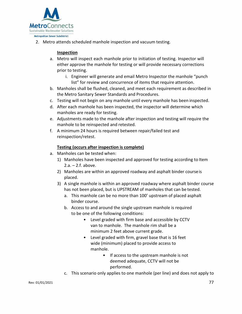
8.3.1 Vacuum Testing Vacuum testing will be required for all manholes in accordance with Metro specifications. All connections, benches, and flow channels shall be installed prior to testing. Manholes located within the roadway must have the binder course of asphalt placed before testing. No temporary asphalt aprons will be allowed around manholes. If flow is transported from a proposed phase through an undeveloped future roadway, the manholes will have to be tested and retested when asphalt is placed. Should a manhole lie upstream of a proposed phase, asphalt shall be a maximum of 100 feet from the center of the last manhole being accepted in
47 Rev: 01/01/2021
that phase. See Inspection and Testing Procedures in Appendix G. If a coating or lining is to be applied to the interior of the manhole, special conditions may be required by Metro based on type of material specified. Testing will include all parts of the manhole below the ring.
Manhole Diameter
(in.)
Test Time (sec.)
48 60
60 75
72 90
84 105
96 120
120 150
8.3.2 Air Testing Sanitary sewer lines (including service laterals) will be required to pass a low‐pressure air test in accordance with the Standard Technical Specifications.
Force mains will be required to pass a leakage test in accordance with American Water Works Association (AWWA) Standard C600 (DIP).
8.3.3 Mandrel Test The mandrel test must be performed only after the sanitary sewer line(s) have been installed for a minimum of 30 days and all adjacent storm drainage with associated manholes have been installed and backfilled to final subgrade. Mandrel testing must be performed in accordance with the Standard Technical Specifications.
8.4 Compaction Testing Compaction testing of all trench and fill areas shall be conducted by a third‐party testing firm in accordance with the Standard Technical Specifications (Appendix B). Metro reserves the right to request evidence of compaction tests at any time during or after construction.
48 Rev: 01/01/2021
Per Greenville County Land Development Regulations, section 6.5.2.B. Compaction Testing: The grading contractor and/or utility installation contractor shall be responsible for providing compaction testing and reporting as described below.
Location and Frequency of Tests. Compaction tests shall be taken at random locations and at random depths at each location to provide a range of sampling depths. The required frequency of testing shall be as follows:
Sanitary Sewer Test along the line at 300’ intervals, and randomly at service connections
at a rate of 1 test per 8 services and at manholes at a rate of 1 test for every 3 manholes. Tests shall be required for all repair work requiring cutting of the asphalt binder course.
Compaction requirements are provided in the Standard Technical Specifications (Appendix B) and as discussed in Section 5.1.
8.5 Wet Well Leakage Testing Leakage tests shall be performed on all wet wells prior to backfilling. Refer to Section 04305 – Concrete Vaults and Chambers in Appendix B – Standard Technical Specifications for further instructions on how to perform testing.
8.6 Force Main Testing Hydrostatic testing is required for all force main piping. Refer to Section 04531 – Sanitary Sewer Force Mains in Appendix B – Standard Technical Specifications for further instructions on how to perform testing.
9.0 Definitions Unless the context specifically indicates otherwise, the meaning of terms used herein shall be as follows:
Appurtenance – Any accessory or other item associated with a sanitary sewer system.
As‐Built Drawing – As‐built drawings are prepared by the contractor. They show on‐site changes to the original construction documents.
Base Flood Elevation (BFE) – According to FEMA (www.fema.gov), BFE is the computed elevation to which flood waters are anticipated to rise during the base (1‐percent‐annual‐ chance) flood event. The 1‐percent‐annual‐chance is also referred to as the "100‐year flood".
49 Rev: 01/01/2021
The BFE is the regulatory requirement for the elevation or flood proofing of structures. The relationship between the BFE and a structure’s elevation determines the flood insurance premium.
Chimney – The cylindrical variable height portion of the manhole structure used to support and adjust the finished grade of the manhole frame. The chimney extends from the top of the cone to the base of the manhole frame.
Easement/Right of way – A permanent non‐possessory interest to use real property for the purpose to construct, operate, maintain, reconstruct, or remove a public utility and appurtenances along, under, and across said easement.
Force Main – A sewer line that carries wastewater under positive pressure.
Gravity sewer – A sanitary sewer pipe and manhole system that utilizes gravity to transport wastewater.
Infiltration – Groundwater that enters the sewer system via such means as pipe cracks, joints, connections, or defects in manhole structures.
Inflow – Surface water which enters the sanitary sewer system via an illegal drain connection (foundation drain, roof drain, yard drain, inlet structure, storm sewer cross connection, or sump pump) or from sources such as leaks around manhole covers.
Lateral – See service connection.
Metro Inspector or Inspector – Designee of Metro for the purposes of observation, inspection and testing of public improvements.
Peak Daily Flow – The maximum flow rate determined by use of the appropriate peaking factor multiplied by the average daily flow.
Pump Station – Any arrangement of pumps, piping, valves, and controls which convey wastewater to a receiving sanitary sewer.
Record Drawings – A record drawing is the final compiled drawing prepared by the engineer of record. These drawings must be prepared, signed and sealed by a Professional Engineer licensed in the State of South Carolina. These drawings mark the notes of the on‐site changes that the contractor makes in the as‐built drawings. The record drawing is surveyed, drawn and compiled as an “engineer approved” set of on‐site changes to the original plans.
50 Rev: 01/01/2021
Service Area – A geographical area served by a public utility or wastewater collection system.
Service Connection – An individual sewer line serving only one (1) building or one (1) residential lot with domestic or industrial wastewater connecting to a gravity sewer system. A service connection does not include the following:
• A gravity sewer line or pump station and force main serving more than one (1) building
or more than one (1) residential lot.
• Sewer lines that have the reasonable ability to serve any additional projects and/or buildings in the future.
Structure – Anything constructed or erected that requires permanent location on the surface of the land. The term "structure" does not include features such as walkways, driveways, recreational courts, flagpoles, light standards, or mailboxes.
Stub – Short length of sewer segment tapped into existing system allowing for future connection.
Tap – Any new service lateral connection to an existing main or manhole.
Ten State Standards – “Recommended Standards for Wastewater Facilities of the Great Lakes‐ Upper Mississippi River Board of State and Provincial Public Health and Environmental Managers.” Latest Edition.
Wastewater – A water supply that has been fouled by a variety of uses. From the standpoint of sources of generation, wastewater may be defined as a combination of the liquid‐ or water‐ carried wastes removed from residences, institutions, and commercial and industrial establishments.
10.0 Abbreviations DIP – Ductile Iron Pipe
Metro – Metropolitan Sewer Subdistrict (dba MetroConnects)
PTC – Permit to Construct
PTO – Permit to Operate
PVC – Polyvinyl Chloride Pipe
ReWa – Renewable Water Resources
51 Rev: 01/01/2021
SCDHEC — South Carolina Department of Health and Environmental Control
Appendix A – Standard Details • Sanitary Sewer Standard Details
• Pump Station and Force Main Standard Details
52 Rev: 01/01/2021
Sanitary Sewer Standard Details
53 Rev: 01/01/2021
Pump Station and Force Main Standard Details
54 Rev: 01/01/2021
Appendix B – Standard Technical Specifications
55 Rev: 01/01/2021
Appendix C – Plan Submittal Process • General Flow Chart: Permit to Construct
• General Flow Chart: Permit to Operate
• Plan Submittal Checklist
• Project Information Form
• Metro Plan Approval Letter
56 Rev: 01/01/2021
Permit to Construct Submittal Process (Appendix C)
57 Rev: 01/01/2021
Permit to Operate Submittal Process (Appendix C)
58 Rev: 01/01/2021
Plan Submittal Checklist
The engineer shall complete this checklist and include it in the initial plan submittal to Metro. All documents shall be delivered in one submittal. Failure to provide a complete submittal package will increase the review and approval time. The review process will not begin until all required items have been submitted.
Check boxes or write “N/A” if not applicable.
Two complete sets of signed and sealed sewer plans (including final grading plans with contours in gray scale). Plans to include an overall development plan view with the following: location map, tax map numbers, lot lines, lot numbers, manholes, line segments, potential bypass locations, lateral locations, road names, and sewer plan and profile segments on same sheet in same direction/orientation. Maximum plan view scale of 1:50 (does not apply to overall development plan).
An overall map showing phasing (if applicable). Note: If phasing changes occur after the plan approval letter has been issued, then an administration fee of $200 shall be applied for each phase change thereafter.
One copy of the sewer design calculations.
A completed (Metro) Project Information Form.
Unrecorded off‐site right‐of‐way legal forms and exhibit (must use Metro templates provided in Appendix H).
A copy of the ReWa Public Main Extension form approved by all sanitary sewer providers receiving flow from the proposed development.
Copies of other permits required for sanitary sewer construction (wetlands, flood plains, encroachments, etc.). If the above mentioned affects the construction or operation of the proposed sewer system and no permit is required, a letter stating such must be signed, sealed, and submitted by the Engineer.
For aerial crossings: Hydraulic calculations are required.
Letters from existing utilities (Duke Energy, Greenville Water System, ReWa, etc.) approving the proposed sanitary sewer crossing.
Payment of Metro’s plan review fees.
59 Rev: 01/01/2021
Project Information Form
PROJECT NAME:
ROAD OWNERSHIP: CHECK ONE ☐PUBLIC ☐ PRIVATE ☐COMBINATION
DEVELOPER:
SITE LOCATION:
DEVELOPMENT TMS#
TMS#
TMS#
TMS#
ENGINEERING FIRM:
ENGINEER:
ADDRESS:
TELEPHONE:
EMAIL:
List all property owners with appropriate tax map numbers for off‐site right of ways necessary to connect this project to an existing sanitary sewer system. Attach additional information as needed. Indicate “N/A” if not applicable.
OWNER(S): TMS#:
OWNER(S): TMS#:
OWNER(S): TMS#:
60 Rev: 01/01/2021
Metro Plan Approval Letter
April 10, 2019
Mr. / Ms. Engineer 100 Main Street, Suite 100 Greenville, SC 29601
Subject: Subdivision ‐ Gravity Sanitary Sewer
The sanitary sewer plans on the above referenced project have been reviewed and approved according to Metropolitans current standards. This approval is for the plans that are on file at Metropolitan’s office only. Any modifications or changes to the plans must receive approval before construction can begin or continue. Metropolitan will own, operate and maintain the system once the project has met the following requirements and the project has final approval from Metropolitan.
A. The Department of Health and Environmental Control (DHEC) must issue a "Permit to
Construct” before any sanitary sewer construction for this project begins. B. The District Office shall be notified in writing by the engineer at least 48 hours prior to
scheduling a Pre Construction meeting and 48 hours prior to beginning construction. C. Sewer lines not in public streets shall be located in the center of a completely cleared and
grubbed 25’ permanent right‐of‐ way. D. Personnel from the design engineering firm must be constantly present for construction
observation and testing. E. A letter of acceptance for ownership, operation and maintenance will not be issued until the
engineer or a representative of the firm has witnessed and approved all required test and inspections and submitted a complete final acceptance package to the District. Included in the final package submittal will be two (2) signed, dated and sealed "As Built" drawings including line profiles and service locations. THE ENGINEER SHALL ASSUME ALL RESPONSIBILITY FOR ACCURACY OF "AS‐BUILT DRAWINGS.
F. Prior to acceptance the system shall be conveyed with the appropriate rights‐of‐way to the District for public use.
Regards, Metropolitan Sewer Subdistrict
Engineering Department CC: SCDHEC
61 Rev: 01/01/2021
Appendix D – Pre‐Construction Meeting Checklist
62 Rev: 01/01/2021
The contractor will not be allowed to begin sewer installation until all required copies of permits, approved shop drawings, and construction drawings stamped “issued for construction” have been received by Metro’s field representative.
Metro Engineering Inspectors shall NOT be responsible for the means, methods, techniques, sequences or procedures of construction selected by Contractor(s) or the safety precautions and programs incident to the work of Contractor(s). Metro Engineering Inspectors are on‐site to view progress, witness testing, and to observe specified materials being installed.
Metro Engineering inspectors typically develop daily field observation reports as part of their inspections. The reports may include, but not limited to, information such as weather conditions, onsite personnel (i.e. supervisor, electrician, competent person, etc.), onsite equipment, work observed, discussions that occurred in the field, etc.
Review “Issued for Construction” drawings with engineer to make sure no revisions have been made (2 sets) since plan approval. If revisions have been made, but have not yet been reviewed by Metro, approval must be obtained prior to construction of the revised portion.
Provide a copy of all SCDOT and County encroachment permits required for the sanitary sewer installation. In addition, provide a copy of all required U.S. Army Corps of Engineers, County Floodplain, and SCDHEC environmental permits to include the “Wastewater Construction Permit”. The engineer shall verify that all permits have been obtained.
The engineer shall record contact information for all present at the meeting, take notes during the meeting, and prepare minutes for distribution to all parties. The engineer shall obtain a copy of the Contractor’s License to submit to Metro.
Check shop drawings and materials on‐site for compliance with specifications. (1 set)
Pipe (PVC, and DIP) Encasement pipe (if bore) Manholes Spiders (if bore) Frames & covers Couplings for PVC to DIP transitions Tees Piers (if applicable)
63 Rev: 01/01/2021
The engineer shall resolve all design issues and shall resubmit any changes to Metro the construction drawings for approval prior to re‐issuing to the contractor for construction.
The Contractor shall be held responsible for release of wastewater when working on or near existing sewer lines. Should a wastewater spill occur the Contractor shall be identified on the SCDHEC Sanitary Sewer Overflow Report and shall be responsible for all clean‐up and applicable fines.
Plugs shall be installed in all tie‐in manholes. The Contractor will be held responsible for any flow, sediment or debris entering the existing systems. Unless prior approval has given by Metro the Contractor shall not remove plugs installed in tie‐in manholes until the “Permit to Operate” has been issued by SCDHEC.
Creek crossings shall require the placement of appropriate stabilization. See Metro details.
Couplings for like materials – (cut joints) will only be allowed when absolutely necessary.
If the project includes a bore, the engineer shall verify location and grade of the encasement pipe and schedule a visual inspection by Metro. Both ends of the encasement pipe shall be accessible during the inspection and the carrier pipe shall not be installed.
Manholes shall be constructed to rim elevations shown on the drawings. Chimneys shall be a maximum of 10‐inches from the cone to the bottom of the frame. If final manhole adjustments result in exceeding the 10‐inch maximum allowance, the manhole shall be adjusted below the cone section to bring it into compliance. The use of four inch frames and covers are not allowed. Manholes in non‐lawn areas must have a minimum rim elevation of 2’ above finish grade.
Less than 90‐degree manhole inverts will not be approved by Metro. The invert shall have a smooth curve with the maximum radius the manhole diameter will allow.
All service lateral tees shall be installed 45‐degrees from the cross section horizontal centerline (10 and 2 o’clock position). No horizontal (9 and 3 o’clock) or vertical (12 o’clock) services will be allowed. There shall be a minimum of 5’ separation between service tees.
64 Rev: 01/01/2021
Any laterals installed under storm drainage with less than 24” separation shall be constructed of DIP. A minimum 18’ single section of DIP shall be centered under the storm drain piping. Special consideration may be made to allow C900. This will be considered on a case by case basis and must be approved by Metro.
The Contractor shall address all grade and drainage issues within the 25’ right of way. The right of way shall be graded to provide access to all manholes by Metro personnel and maintenance equipment. Right of way access shall be verified by the engineer and approved by Metro prior to sewer acceptance.
Testing – Engineer/Representative and Metro Inspector are required to witness all testing (deflection, air, and vacuum). Metro forms must be used to record all test results. The pipe deflection test shall be performed a minimum of 30 days after installation. All testing must be scheduled with a Metro Inspector.
• The vacuum test and final inspection shall be done after the binder has been placed on the road and prior to final CCTV Inspection. All manholes, including doghouse manholes, must pass a vacuum test.
• All service laterals, including laterals connecting to manholes, shall require low‐ pressure testing.
• Low‐pressure testing of sewer pipe shall be performed in accordance with ASTM F1417 (Table 1, 1.0 psig pressure drop). Maximum gauge reading to be 30 psi. Adjust the test pressure by adding 0.43 psig per foot of groundwater head (do not exceed 9.0 psig). Refer to Section 8 of Uni‐Bell’s Recommended Practice for Low‐ Pressure Air Testing of Installed Sewer Pipe, UNI‐B‐6‐98 for guidance on determining groundwater elevations.
• Where tubes are installed in manholes to determine groundwater elevations, the manhole must be repaired once low‐pressure testing is completed. Manholes must be vacuum tested after the manhole is repaired.
• Engineer shall be prepared to provide calculations of test times and groundwater adjustments to Metro’s inspector prior to testing operations. Calculations shall be submitted to Metro along with the test forms in the final submittal package.
After cleaning the lines, the contractor shall call the engineer to schedule a final inspection with Metro’s Inspector. The engineer shall draft a punch list during the final inspection. A copy of the punch list shall be submitted to Metro’s Inspector. Upon satisfactory completion of all punch list items (including acceptance of easments for CCTV access) and approval of the engineers final project package, Metro shall schedule the final CCTV inspection.
65 Rev: 01/01/2021
• Metro will forward repair information, if required, or Metro’s letter of acceptance to the engineer. All Metro CCTV inspections and invoices will be addressed and sent to the engineer.
The contractor shall warrant the work for one year from the date of the Metro’s Acceptance Letter. Metro shall inspect the line prior to the year anniversary and if required shall forward a punch list of deficiencies to the engineer. The engineer shall manage the rework and notify Metro upon completion to schedule the final re‐ inspection.
As part of the final submittal package, submit a copy of the contractor’s final invoice for the sanitary sewer system installation. Metro will use this to determine the value of the new sewer system assets.
Project Name
Contractor
Signature Engineer/Representative
Print Name Date
Signature Metro Inspector
Print Name
Date
Signature
Print Name
Date
Design and Specifications Guide
66 Rev: 01/01/2021
Appendix E ‐ Sanitary Sewer Pump Station Policy
Design and Specifications Guide
67 Rev: 01/01/2021
Resolution #2019‐ 11
RESOLUTION TO ADOPT AND APPROVE A NEW PUMP STATION POLICY FOR METROPOLITAN SEWER SUBDISTRICT
WHEREAS, In an effort to adapt to the increased challenges of providing sanitary sewer service, the Commissioners of Metropolitan Sewer Subdistrict, ("Metropolitan") have determined that it is necessary and desirable to formally adopt a new policy regarding the ownership and operation of Pump Stations within the Metropolitan service area (the "Pump Station Policy").
NOW THEREFORE, BE IT RESOLVED, that the Pump Station Policy attached to this Resolution as Exhibit A, is hereby adopted and shall take effect commencing on the date hereof.
FURTHER RESOLVED, that the above resolution is hereby adopted to take effect commencing this_19_ day of October, 2019.
an, Metropolitan Sewer Subdistrict
68 Rev: 01/01/2021
Design and Specifications Guide
Metropolitan Sewer Sub District Pump Station Policy
In an effort to adapt to the increased challenges of providing sanitary sewer service, the Commissioners of Metropolitan Sewer Subdistrict, ("Metropolitan") have determined that it is necessary and desirable to formally adopt the following policy regarding the ownership and operation of Pump Stations within the Metropolitan service area (the "Pump Station Policy").
Definitions
a) Pump Station ‐ a sewage collection lift system approved by Metropolitan commonly comprised of wet well structures, dry pit structures, generators, electrical control panels, valve vault structures, forcemain and all structures and appurtenances required for the proper operation and maintenance of the pump station system. A Pump Station shall also include all sanitary sewer collection components located within a fenced area and the access drive to the Pump Station site.
b) Regional Pump Station ‐ A Pump Station that serves a significant service area. Typically, the influent gravity line size is equal to or greater than 18". Regional Pump Stations are typically owned and operated by Renewable Water Resources ("ReWa").
c) Metropolitan Pump Station ‐ A Metropolitan Pump Station that serves a moderate developable service area. Typically, the influent gravity line size ranges from 1O" to 16" and will serve a range from approximately 600 single family homes (180,000 gallons per average day) to 2,500 single family homes (750,000 gallons per average day).
d) Temporary Pump Station ‐ A Metropolitan Pump Station that serves a limited developable area or considered a short‐term solution for the current master planning documents. Typically, these pump stations have an 8" influent gravity line size.
Planning
a) All proposed Pump Stations shall be reviewed by Metropolitan with respect to
determining the location, size, ownership, and justification. Factors that will be considered in the reviews are:
69 Rev: 01/01/2021
Design and Specifications Guide
i) How the Pump Station fits into ReWa & Metropolitan's current Masterplan , the 2018 Upstate Roundtable Plan,
Greenville County planning and municipal planning.
ii) Gravity sewer options that have been evaluated and reviewed by Metropolitan and ReWa.
iii) Impact to Metropolitan's facilities with respect to capacity and operations.
iv) Rate of return on investment for Pump Station projects that include Metropolitan funding.
v) Limiting the use of Temporary Pump Stations for long term (greater than 10 years) service solutions.
b) Ultimately, gravity sanitary sewer systems are the preferred method of providing service due to the efficiency, low risk/consequence and life cycle.
Metropolitan Ownership of Pump Stations
a) Metropolitan may seek additional funding from the developer to support the operation and maintenance of a Pump Station, fund a portion of an upgrade necessary to serve the proposed service area, or to fund a portion of a future project that would allow for the abandonment or removal of the Pump Station . A summary of these options are as follows:
i) A lump sum payment for the first ten years of projected operation and maintenance costs determined at the time of Metropolitan's approval of the project. Payment of these costs would be required prior to issuing the Flow Acceptance Letter for the project.
b) Metropolitan's decision to take ownership of a Pump Station will be based on
consideration of the above factors and options, including customer costs and fees. Metropolitan reserves the right to determine what is in the best interest of its operations and facilities, and its customers.
70 Rev: 01/01/2021
Design and Specifications Guide
c) Each Pump Station must meet all Metropolitan standards at the time of acceptance.
d) Fee simple title (or exclusive use easements) and access to allproperty comprising a Pump Station must be conveyed to Metropolitan free and clear of any encumbrances or liens. Inaddition, all necessary force main right of ways shall be conveyed to Metropolitan.
e) All costs incurred for design, construction, inspection, testing, title examination, and
other costs related to the installation of a Pump Station shall be borne by the developer/grantor thereof. The initial operating costs (prior to Metropolitan accepting ownership) relating to a Pump Station will be the developer's responsibility.
f) The construction of any new Pump Station to be conveyed to Metropolitan must commence within one (1) year of Metropolitan's approval of the Pump Station and all construction must be completed within two (2) years of the Metropolitan approval. If these conditions are not met, then either an extension must be filed or the approval becomes void and a new submittal must be made.
g) Other factors as Metropolitan may deem necessary or appropriate for determining the feasibility of owning, operating and maintaining the Pump Station.
h) The General Manager/or their designee is authorized to determine if Metropolitan will take ownership of a Pump Station based upon the parameters set forth inthis policy.
The Applicant’s Engineer shall complete and submit this checklist along with other required items. If any required items deemed incomplete by Metro, it will be noted in the form below and returned to the Applicant’s Engineer. Metro will not issue an acceptance letter until all required items have been received and deemed complete.
Check boxes to denote completion or write “N/A” if not applicable to project.
DESIGN CALCULATIONS – DESIGN FLOW & OPERATING POINT
Operating Point – plot TDH vs. flow rate onto pump curve; include pump impellor size and operating point
DESIGN CALCULATIONS – SURGE RELIEF CHECK
Required Items
Engineer Metro
Complete Complete
Condition – all pumps running
Wave Velocity Calculations
Water Hammer Pressure Calculations
Total Pressure – equal to water hammer pressure plus static head (check total pressure against pressure ratings for valves & piping; i.e. provide class & thickness)
DESIGN CALCULATIONS – EMERGENCY STORAGE
Engineer Metro Required Items
Complete Complete
Storage between overflow elevation (lowest pipe RIM elev.) and lead pump on elevation
Storage Calculations:
Storage Time = Total Storage / ADF
Total Storage = (Wet Well Storage) + (Pipe Storage) + (Manhole Storage)
Verify Storage Time ≥ Maximum Power outage time over last 5 years
Total Storage > Volume in force main to 1st downstream
PUMP STATION DESIGN REVIEW CHECKLIST
74 Rev: 01/01/2021
DESIGN CALCULATIONS – SUPPORTING DOCUMENTATION
Engineer Metro Required Items
Complete Complete
Basin Map Delineating Service Area
100‐year flood map (FEMA) or high ground water elevation (SCS)
Provide cut sheets or product literature for the following: Pumps – include pump curves, motor data,
electrical data, arrangement dimensions
Valves – include max. operating pressure info
Power Source (utility provider)
Hydraulic Calculations prepared by a Professional Engineer licensed in the State of South Carolina
SIGNATURES (SIGN AND DATE)
DATE: METRO DEVELOPMENT PROJECT ENGINEER: DATE: APPLICANT’S ENGINEER:
75 Rev: 01/01/2021
Design and Specifications Guide
Appendix G – Construction Testing Forms • Inspection and Testing Procedures
• Low‐Pressure Air and Manhole Vacuum Testing Times
• Manhole Vacuum Test Form
• Low Pressure Air Test Form
• Mandrel Test Form
76 Rev: 01/01/2021
General Workflow: Inspection and Testing
After plan approval by MetroConnects, the inspection process will begin. The following meeting, inspections, and testing are required in the order shown:
1. Project preconstruction meeting. 2. Metro performs periodic site observations throughout the construction process. 3. Metro Inspectors have the authority to make field determinations as needed and at
their discretion. 4. Sewer lines are installed and backfilled to final subgrade. 5. All inspection requests are to be made through the [email protected]
email address. 6. At Metro’s discretion, a reinspection or retest may be required if field changes are made
after inspections or tests are completed. 7. Refer to Appendix I – Fee Schedule of the Metro Sanitary Sewer Standards and
Procedures manual for fees associated with inspections and reinspections.
Line Testing 1. Metro Inspector is notified by Engineer when last sewer line is installed for the 30‐day
countdown to begin that will allow testing to be performed. 2. Contractor shall flush and clean all lines prior to testing. 3. Metro Inspector is contacted by Engineer to request and schedule mandrel and/or low‐
pressure air test inspection. 4. Metro attends scheduled mandrel and/or low‐pressure air test inspection.
a. If the Metro inspector determines the lines have not been flushed and cleaned, testing will be stopped and rescheduled for a time after lines have been flushed and cleaned.
b. If Metro inspector determines final subgrade has not been achieved, testing will be stopped and the 30‐day countdown will restart after final subgrade is achieved.
5. Contractor performs the following after line testing is complete: a. Places binder course of asphalt. b. Achieves final grade for sewer lines within a vegetated right‐of‐way.
Manhole Interior Inspection and Vacuum Testing (occurs after line testing is complete) 1. Metro Inspector is contacted by Engineer to request and schedule manhole inspection
2. Metro attends scheduled manhole inspection and vacuum testing.
Inspection a. Metro will inspect each manhole prior to initiation of testing. Inspector will
either approve the manhole for testing or will provide necessary corrections prior to testing.
i. Engineer will generate and email Metro Inspector the manhole “punch list” for review and concurrence of items that require attention.
b. Manholes shall be flushed, cleaned, and meet each requirement as described in the Metro Sanitary Sewer Standards and Procedures.
c. Testing will not begin on any manhole until every manhole has been inspected. d. After each manhole has been inspected, the inspector will determine which
manholes are ready for testing. e. Adjustments made to the manhole after inspection and testing will require the
manhole to be reinspected and retested. f. A minimum 24 hours is required between repair/failed test and
reinspection/retest.
Testing (occurs after inspection is complete) a. Manholes can be tested when:
1) Manholes have been inspected and approved for testing according to Item 2.a. – 2.f. above.
2) Manholes are within an approved roadway and asphalt binder course is placed.
3) A single manhole is within an approved roadway where asphalt binder course has not been placed, but is UPSTREAM of manholes that can be tested. a. This manhole can be no more than 100’ upstream of placed asphalt
binder course. b. Access to and around the single upstream manhole is required
to be one of the following conditions: • Level graded with firm base and accessible by CCTV
van to manhole. The manhole rim shall be a minimum 2 feet above current grade.
• Level graded with firm, gravel base that is 16 feet wide (minimum) placed to provide access to manhole.
• If access to the upstream manhole is not deemed adequate, CCTV will not be performed.
c. This scenario only applies to one manhole (per line) and does not apply to
78 Rev: 01/01/2021
multiple manholes along a line upstream of placed asphalt binder. d. This manhole will have to be retested and the associated lines will
need CCTV performed again after asphalt binder course is placed. 4) Manholes are within an approved roadway where asphalt binder course has
not been placed, but are DOWNSTREAM of manholes that can be tested. a. Access to and around the downstream manholes are required to be
one of the following conditions: • Level graded with firm base and accessible by CCTV van to
manholes. The manhole rims shall be a minimum 2 feet above current grade.
• Level graded with firm, gravel base that is 16 feet wide (minimum) placed to provide access to manholes.
• If access to the downstream manholes is not deemed adequate, CCTV will not be performed.
b. These manholes will have to be retested and the associated lines will need CCTV performed again after asphalt binder course is down.
5) Manholes are in vegetated right‐of‐way and final grade has been achieved.
Initial Inspection (occurs after testing is complete) 1. Metro Inspector is contacted by Engineer to request the Initial Inspection. 2. Metro attends scheduled Initial Inspection. Engineer is required to bring a hard copy of
the as‐builts/Record Drawings and Engineer’s Final Certification Letter for Metro’s use. **Inspections will not occur without a hard copy of as‐builts/Record Drawings and
Engineer’s Final Certification Letter. a. Metro inspector identifies “punch list” items for Engineer to compile a draft. b. Engineer emails “punch list” items to Metro inspector for review and
concurrence of items that require attention. c. Engineer notifies owner and contractor of ”punch list” items.
3. Items identified on the “punch list” are corrected.
Final Inspection (occurs after punch list items are corrected) 1. Metro Inspector is contacted by Engineer to request a Final Inspection. 2. Metro performs Final Inspection to verify “punch list” items have been corrected. 3. If “punch list” items are corrected, Metro inspections are complete. If there are
discrepancies, Metro inspectors will identify the discrepancies and wait to be contacted for a reinspection.
4. The reinspection process will continue until all discrepancies identified have been corrected.
79 Rev: 01/01/2021
As‐built/Record Drawing Review Performed (occurs after Final Inspection) 1. See Section 9.0 of the Metro Sanitary Sewer Standards and Procedures for as‐
built/Record Drawings requirements.
CCTV and Metro Acceptance Letter (occurs after corrections made from Final Inspection)
1. Metro Inspector initiates CCTV process. 2. Metro performs CCTV inspections, identifies “punch list” items, and provides those
items to the Engineer. 3. “Punch list” items are corrected. 4. Metro performs CCTV reinspection (if needed) and, if no discrepancies, signs off on the
work. If there are remaining discrepancies, the reinspection process will continue until all discrepancies identified have been corrected.
5. After Metro signs off on CCTV inspection, the CCTV invoice is sent to the Engineer.
80 Rev: 01/01/2021
Low‐Pressure Air and Manhole Vacuum Testing Times
Manhole Vacuum Testing Time
Manhole Diameter (Inches)
Test Time (seconds)
48 60 60 75 72 90 84 105 96 120
120 150
Low Pressure Air Testing Times
MINIMUM SPECIFIED TIME REQUIRED FOR A 1.0 PSIG PRESSURE DROP FOR SIZE AND LENGTH OF PIPE INDICATED FOR Q = 0.0015
Pipe Diameter
(in.)
Specification Time for Length of Pipe Shown (min:sec)
*Source: Unibell PVC Pipe Association – Table UNI‐B‐6‐98
(Signature)
81 Rev: 01/01/2021
Manhole Vacuum Test Form
Project Name: Contractor:
Location Pressure Test Time (min.)
Pass/ Fail
Line ID
Manhole No. or Station
Start (inHg)
Drop (inHg)
In paved areas, asphalt binder or aggregate base course must be in place prior to vacuum test.
I, , (engineer or engineer's representative), certify the following: (Printed Name)
1. I have witnessed all vacuum testing. 2. All testing was performed in accordance with Metropolitan Sewer Subdistrict requirements. 3. The information on this form is true and accurate.
Witnessed by Contractor:
(Signature) (Printed Name)
Date:
Date: (Signature)
82 Rev: 01/01/2021
Low‐Pressure Air Test Form
Project Name: Contractor:
Location Pipe Test Test Pressure Pass/ Fail
Line ID
Starting
Manhole
Ending
Manhole
Dia. (in.)
Length
(ft.)
Time (min.)
Groundwater Adj. Start
(psig) (psig)
Drop (psig)
Minimum test pressure = 3.5 psig + groundwater adjustment (add 0.43 psig/foot groundwater head), max test pressure = 9.0 psig
I, , (engineer or engineer's representative), certify the following:
(Printed Name)
1. I have witnessed all low‐pressure air testing. 2. All testing was performed in accordance with Metropolitan Sewer Subdistrict requirements. 3. The information on this form is true and accurate.
Witnessed by Contractor:
(Signature) (Printed Name)
Date: (Signature)
83 Rev: 01/01/2021
Mandrel Test Form
Project Name: Contractor:
Location Pipe Pass/ Fail
Failure Station Number
Line ID
Starting Manhole
Ending Manhole
Dia. (in.)
Length (ft.)
I, , (engineer or engineer's representative), certify the following: (Printed Name)
1. I have witnessed all mandrel testing. 2. All testing was performed in accordance with Metropolitan Sewer Subdistrict requirements. 3. The information on this form is true and accurate.
Witnessed by Contractor: (Signature) (Printed Name)
84 Rev: 01/01/2021
Appendix H – Final Project Submittal • Typical 25’ Sanitary Sewer Right of way and Easement (Figure 3)
• Final Project Submittal Checklist
• Record Drawing AutoCAD Checklist
• Certification Letter Requirements
• Example Engineer’s Certification Letter
• CCTV Inspection Report
85 Rev: 01/01/2021
Typical 25’ Sanitary Sewer Right of Way (Figure 3)
86 Rev: 01/01/2021
Final Project Submittal Checklist
The engineer shall complete this checklist and include it in the final project submittal to MetroConnects. All documents shall be delivered in one submittal. If any items are incomplete or unclear, it will be noted on the bottom portion of this form and the form shall be returned to the engineer. MetroConnects shall not proceed with the CCTV inspection until all items have been satisfactorily received.
Check boxes or write “N/A” if not applicable.
Two sets of Record Drawings signed and sealed by the Engineer of record. Drawings shall include plan view and line profiles and clearly identify manholes and line segments to be permitted including service lateral locations, service lengths and depths at end of service.
Email Record Drawing AutoCAD file according to requirements listed in Appendix H. Emailed Date:
One copy of engineer's certified low‐pressure air, mandrel, and manhole vacuum tests. If ground water is encountered: include low‐pressure air test calculations, water table elevations, and steps implemented to alleviate the ground water. (See Metro Forms, Appendix G.)
One copy of engineer's certified pump station and force main test results, if applicable.
Engineer's certification letter for sanitary sewer system. (See Certification Letter requirements ‐ next page).
Sanitary sewer trench backfill compaction tests (within roadways and fill areas).
Verification and submittal of actual cost for sewer installation (total cost of labor & materials for the phase or section being permitted only).
By: Date:
87 Rev: 01/01/2021
Record Drawing AutoCAD Checklist
Record Drawings shall be submitted by email and in DWG format. All record drawings shall be based off survey data and projected in the SC state plane coordinate system (NAD 1983) horizontal and (NAVD 88) vertical. The drawing should not be rotated.
The following layers must be included and labeled as such. Additional layers are not to be included.
1) Exterior boundary of overall development (V‐SURV‐LINE)
2) Property corners (V‐SURV‐MONUMENT)
3) Lot lines (V‐SURV‐LINE)
4) Lot numbers (V‐SITE‐TEXT)
5) R/W lines (V‐SITE‐LINE)
6) Road names (V‐SITE‐TEXT)
7) Main lines to CL of manhole (V‐SITE‐SSWR)
8) Services laterals
9) Manholes cl of manhole base ‐ not cl of ring and cover (V‐SURV‐STRC)
Northing
Easting
Rim elevation
Depth (distance from rim to invert out)
IF APPLICABLE
1) Force main (V‐SITE‐SSWR)
2) Pump Station wet well (V‐SITE‐PS)
Northing
88 Rev: 01/01/2021
Easting
Rim elevation
Bottom elevation
3) Air Release Valves (V‐SITE‐STRC)
Northing
Easting
Rim elevation
89 Rev: 01/01/2021
Certification Letter Requirements
Acceptance letters will not be issued without the following information.
A: Subdivision Name
B: Number of lots and lot numbers requesting approval in this section or phase (State if the Permit
to Operate is a partial permit of the overall Permit to Construct).
C: Number of manholes, manhole numbers and manhole station numbers. (Manholes must match numbering on record drawing.)
D: Make statement: “To the best of my knowledge, information, and belief, I certify that construction is complete and in accordance with the approved plans and specifications.”
E: Total linear footage of pipe installed: (pipe type, size and footage of each)
F: Line segments to be approved
G: The DHEC construction permit number. State any modifications to the original permit to construct and an explanation of modifications, if applicable. Make note of any modifications or upgrades to existing lines covered in the permit.
H: All roads/streets must have names shown on as built drawing.
I: List water table elevations during pipe installation and/or testing. Describe methods implemented to alleviate water accumulation. If no water was encountered include statement in certification letter that “No groundwater was encountered during construction or testing.”
90 Rev: 01/01/2021
Example Engineer’s Certificaton Letter Underlined features to be project specific:
May 4, 2018
Robert Arms Metropolitan Sewer Subdistrict 120 Augusta Arbor Way Greenville SC 29605-5226
Re: Jasper Mill Subdivision
Project # 18100 DHEC Permit 12345-WW
Dear Mr. Arms,
Representatives of ABC Engineering & Associates, Inc. have made field inspections and conducted the required testing for the above referenced project. No groundwater was encountered during construction and testing. To the best of my knowledge, information, and belief, I certify that construction is complete and in accordance with the approved plans and specifications. This certification is based on periodic observations of construction and a final inspection for design compliance by me or a representative of this office who is under my supervision.
The overall permit to construct covers 2,000 LF of 8” sewer main, (14) manholes and service 65 single family residences of the Jasper Mill Subdivision. We are requesting a Permit to Operate for the following sewer lines:
Line “A” MH# 1-9
Line “B” MH# 1-3
Line “C” MH# 1-2
Length of 8” main: +/- 2,000 LF
Number of manholes: 14
Serving lots 1-65: (single family residences)
Included for your information is the testing data, a copy of the construction permit, two sets of record drawings and a CD containing pdf’s of the record drawings. We are requesting a letter accepting ownership, operations, and maintenance for the above mentioned sewer system. If you have any questions or need any additional information, please give me a call.
Sincerely,
Mr. / Ms. Engineer, P.E. ABC Engineering & Associates, Inc.
91 Rev: 01/01/2021
CCTV Inspection Report Sent To - Engineer: Attention:
Metropolitan Sewer Subdistrict (Metro) has completed a CCTV inspection for (project name) to verify that the sanitary sewer system has been constructed to Metro specifications and standards. The results of the CCTV inspection are:
Deficiencies have been identified and shall be repaired prior to MSSD acceptance of the sewer system.
Copies of the CCTV video and punch list are available to the Engineer and may be picked up at Metro.
Copies of the punch list are included with this form.
The Engineer shall notify the contractor of these deficiencies and verify that repairs have been made. Any sewer lines that are repaired shall be retested in accordance with Metro testing procedures. The Engineer shall notify Metro after repairs and testing are complete by filling out the information below, signing and returning this document to Metro.
By: (Metro) Date:
I (engineer), certify to the best of my knowledge and belief, that all repairs required to correct the deficiencies identified by the CCTV inspection have been completed and that the project is ready for a follow-up inspection. (attach test forms)
(signature) Date:
A follow-up CCTV inspection indicates that deficiencies remain and that additional work is required. The Engineer shall follow the procedure as outlined above.
I (engineer), certify to the best of my knowledge and belief, that all repairs required to correct the deficiencies identified by the follow-up CCTV inspection have been completed and that the project is ready for a follow-up inspection. (attach test forms)
The sanitary sewer system meets all Metro requirements and specifications. The Metro final approval letter shall be mailed to your office within several working days.
By: (Metro) Date:
92 Rev: 01/01/2021
Title Certificaton to Metropolitan Sewer Subdistrict
The undersigned has carefully examined the public records of Greenville County, South Carolina and hereby makes the following certifications to Metropolitan Sewer Subdistrict (“Metropolitan”):
The undersigned has served as legal counsel for [insert name of developer](the “Owner”) in connection with that certain Dedication and Conveyance of Sanitary Sewer Line and Right of Way attached hereto as Exhibit A (the “Dedication Agreement”).
The Owner is the fee simple owner and has good marketable title to the real property, easement areas, right of way areas, equipment, facilities, pipes, valves, wastewater lines, pump stations and all other property comprising the sanitary sewer system being conveyed to Metropolitan under the Dedication Agreement (the “Sewer Facilities”).
The Sewer Facilities are being conveyed to Metropolitan under the Dedication Agreement free and clear of all liens and encumbrances.
The Owner and has the full power and authority to convey the Sewer Facilities to Metropolitan pursuant to the terms and conditions of the Dedication Agreement.
This Title Certificate is made and delivered for the benefit of Metropolitan Sewer Subdistrict and may be relied upon by Metropolitan in accepting the transfer and ownership Sewer Facilities from the Owner pursuant to the terms and conditions of the Dedication Agreement.
IN WITNESS WHEREOF, this Title Certification is executed to be effective as of , 20 .
[Insert Name of Law Firm] By:
Its:
Print Name:
93 Rev: 01/01/2021
Exhibit A ‐ Dedication Agreement
94 Rev: 01/01/2021
STATE OF SOUTH CAROLINA ) DEDICATION AND CONVEYANCE OF ) SANITARY SEWER LINE AND RIGHT OF WAY COUNTY OF GREENVILLE ) [GRANTEE IS A POLITICAL SUBDIVISION OF THE STATE OF SOUTH CAROLINA EXEMPT FROM RECORDING FEES UNDER S.C. CODE ANN., SECTION 12-24-40(2)] KNOW ALL MEN BY THESE PRESENTS, that ("Grantor"), in consideration of One ($1.00) Dollar to the Grantor paid in hand at and before the sealing of these presents by the Grantee, the receipt of which is hereby acknowledged, has granted, bargained, sold, released, dedicated and conveyed, and by these presents does grant, bargain, sell, release, dedicate and convey to the METROPOLITAN SEWER SUBDISTRICT, its successors and assigns ("Grantee"): Those certain sanitary sewer lines, manholes, valves, adjuncts and appurtenances (but
excluding any service line or lines, or any part thereof, outside of the easement herein dedicated and conveyed) installed and located in, under or along the property of Grantor as shown on a plat entitled __________________________________, prepared by __________________________, dated ________________________________, recorded in Plat Book ____, Page ____, and also being more particularly shown and described on an As-Built drawing of said lines entitled "__________________________" prepared by __________________________________________, on file with Grantee, which are by reference made a part of this description;
Together with and including a permanent right of way and easement extending twelve and
one-half (12.5) feet on each side of the centerline of the sanitary sewer line(s) for purposes of the operation, maintenance, repair, replacement or relocation of such lines and appurtenances (the "Right(s) of Way").
The above described property is all or a portion of that conveyed to Grantor herein by Deed
of _________________________________________, recorded _____________ in the Office of the Register of Deeds for Greenville County, South Carolina in Deed Book ____, Page ____.
[Complete the following paragraph if off-site easements are to be conveyed.]
ALSO, certain off-site easements acquired by Grantor as more particularly described on Exhibit "A" attached hereto and incorporated herein.
TOGETHER WITH all and singular the rights, members, hereditaments and appurtenances to said premises belonging or in any wise incident or appertaining, including, without limitation, the right of ingress and egress to the above Right(s) of Way over and through lands of Grantor and Grantor’s heirs or successors and assigns; to have and to hold all and singular the premises before mentioned unto the Grantee, and the Grantee's successors and assigns, forever, subject to the terms and provisions hereof. The Right(s) of Way herein dedicated and granted include the right, privilege and easement of the Grantee to install, repair,
95 Rev: 01/01/2021
and/or add to and extend existing lines and appurtenances now or hereafter constructed, within the boundaries of the Right(s) of Way herein described and conveyed for the purpose of serving other properties or otherwise, without any further approval, consent or authorization of the Grantor, or the Grantor’s heirs, successors or assigns, and to operate, maintain, repair and replace such lines as installed or extended. No building, improvement or other structure shall be constructed or installed within the boundaries of the Right(s) of Way nor so close thereto as to impose any load on the existing lines and appurtenances; and the Grantee shall have the right to cut away and keep clear of the sanitary sewer lines and appurtenances any and all vegetation that might, in the opinion of Grantee, endanger or injure the sewer lines or their appurtenances, or interfere with their proper operation and maintenance. Without limiting the right of ingress and egress to and from the Right(s) of Way and sanitary sewer system herein dedicated and conveyed for the purpose of exercising the rights, privileges and easements hereby granted, in the event that said Right(s) of Way and sanitary sewer system are within the boundaries of a gated subdivision, community or development, or in any location where access is otherwise controlled or restricted, the Grantee shall at all times be afforded access and shall be given an access code for any coded entrance gate by the Grantor or its heirs, successors and assigns. Said access code shall not be changed, altered or deleted without the prior consent and approval of the Grantee or its successors and assigns. The Grantor hereby acknowledges and agrees that in the event a building or other structure should be erected contiguous to the Right(s) of Way, no claim for damages shall be made by the Grantor, his heirs or assigns, on account of any damage that might occur to such structure, building or contents thereof due to the operation or maintenance, or negligent operation or maintenance of the lines and appurtenances within said Right(s) of Way, or any accident or mishap that might occur therein or thereto. GRANTOR WARRANTS AND REPRESENTS that except as provided below, the property and the rights and easements herein conveyed are not subject to any mortgage, judgment or lien other than for property taxes which are not yet past due, nor to any encumbrance which would interfere with Grantee's ability to operate, maintain, repair, replace, relocate or otherwise own and utilize the lines and system described above. In the event of a mortgage on the property herein conveyed, Grantor has obtained the consent and joinder of the Lender/Mortgagee as provided in the attached Joinder and Consent of Lender/Mortgagee attached hereto. GRANTOR DOES HEREBY bind itself and its heirs or successors to warrant and forever defend all and singular said premises unto the Grantee and the Grantee's heirs or successors and against the Grantor and the Grantor's heirs or successors and against every person whomsoever lawfully claiming or to claim the same or any part thereof.
[SIGNATURE PAGE TO FOLLOW]
96 Rev: 01/01/2021
[INDIVIDUAL GRANTOR SIGNATURE PAGE]
IN WITNESS WHEREOF, the Grantor has executed this Dedication and Conveyance of Sanitary
Sewer Line and Right of Way this _____ day of ______________, 20___. SIGNED, sealed and delivered in the presence of: GRANTOR: Witness 1
Print Name: Print Name: Witness 2 Print Name: STATE OF _____________ )
) ACKNOWLEDGMENT COUNTY OF ___________ ) (Individual)
I, the undersigned Notary Public for the State of South Carolina, do hereby certify that _________________________________, [Grantor(s)], personally appeared before me this day and acknowledged the due execution of the foregoing instrument. Witness my hand and seal this _____ day of _______________________, 20___. (SEAL) Notary Public for State of ____________________ Print Name: _______________________________ My commission expires: _____________________
97 Rev: 01/01/2021
[ENTITY GRANTOR SIGNATURE PAGE]
IN WITNESS WHEREOF, the Grantor has executed this Dedication and Conveyance of Sanitary
Sewer Line and Right of Way this _____ day of ______________, 20___. SIGNED, sealed and delivered in the presence of: GRANTOR: Name of Entity By: Witness 1
Its: Print Name: Print Name: Witness 2 Print Name: STATE OF __________________ )
) ACKNOWLEDGMENT COUNTY OF _______________ ) (Entity)
I, the undersigned Notary Public, do hereby certify that _____________________ [name of individual], the ___________________ [title of individual] of the above named Grantor personally appeared before me this day and acknowledged the due execution of the foregoing instrument. Witness my hand and seal this _______ day of ______________, 20_____. (SEAL) Notary Public for State of ____________________ Print Name: _______________________________ My commission expires: _____________________
98 Rev: 01/01/2021
CONSENT AND JOINDER OF LENDER/MORTGAGEE
_________________________________ ("Lender/Mortgage"), the owner and holder of a certain encumbrance, to wit: that certain mortgage encumbering the property described in the foregoing Dedication and Conveyance, which mortgage is recorded in Mortgage Book _____ at page _____ of the Office of the Register of Deeds of Greenville County, South Carolina, does hereby join in the grant of the dedication and conveyance for the purpose of consenting to the same, hereby agreeing to honor and recognize the same hereafter, in accordance with its terms. In Witness Whereof, the undersigned has executed this Consent and Joinder this day of ____________________, 20___. WITNESS Name of Lender/Mortgagee By: Witness 1
Its: Print Name: Print Name: Witness 2 Print Name: STATE OF ________________ )
) ACKNOWLEDGMENT COUNTY OF _____________ ) (Lender/Mortgagee)
I, the undersigned Notary Public, do hereby certify that _____________________, the ___________________ of the above named Lender/Mortgagee personally appeared before me this day and acknowledged the due execution of the foregoing instrument. Witness my hand and seal this _______ day of ______________, 20_____. (SEAL) Notary Public for State of ____________________ Print Name: _______________________________ My commission expires: _____________________
99 Rev: 01/01/2021
EXHIBIT "A"
Offsite Easements
A certain off-site easement acquired by Grantor from ___________________________, by instrument dated _____________________ and recorded in the Office of the Register of Deeds for Greenville County in Deed Book ______________, Page __________, together with the lines, manholes, valves, adjuncts and appurtenances constructed and installed thereon. A certain off-site easement acquired by Grantor from ___________________________, by instrument dated _____________________ and recorded in the Office of the Register of Deeds for Greenville County in Deed Book ______________, Page __________, together with the lines, manholes, valves, adjuncts and appurtenances constructed and installed thereon. A certain off-site easement acquired by Grantor from ___________________________, by instrument dated _____________________ and recorded in the Office of the Register of Deeds for Greenville County in Deed Book ______________, Page __________, together with the lines, manholes, valves, adjuncts and appurtenances constructed and installed thereon. A certain off-site easement acquired by Grantor from ___________________________, by instrument dated _____________________ and recorded in the Office of the Register of Deeds for Greenville County in Deed Book ______________, Page __________, together with the lines, manholes, valves, adjuncts and appurtenances constructed and installed thereon. A certain off-site easement acquired by Grantor from ___________________________, by instrument dated _____________________ and recorded in the Office of the Register of Deeds for Greenville County in Deed Book ______________, Page __________, together with the lines, manholes, valves, adjuncts and appurtenances constructed and installed thereon. GREENVILLE 1528511.3
100 Rev: 01/01/2021
101 Rev: 01/01/2021
102 Rev: 01/01/2021
STATE OF SOUTH CAROLINA )
________________________
Tax Map Number
) RIGHT OF WAY COUNTY OF GREENVILLE ) (Sanitary Sewer)
1. KNOW ALL MEN BY THESE PRESENTS: That ___________________________________, (hereinafter called the “Grantor”), in consideration of $___________________ paid or to be paid by _______________________________________ (hereinafter called the “Grantee”), does hereby grant and convey unto the said Grantee a right of way and easement over the land of Grantor situate in Greenville County, South Carolina, the deed to which is recorded in the Office of the Register of Deeds for Greenville County in Book ______ at Page ___________ , said lands being briefly described as: hereinafter called the “Grantor Property”).
2. The right of way and easement conveyed to Grantee by Grantor hereunder is shown on the drawing attached hereto as Exhibit A and incorporated herein by this reference. During construction, the right of way and easement area conveyed herein to Grantee shall have a total width of _________________ feet, as more particularly shown on Exhibit A (hereinafter called the “Construction Right of Way”). Upon completion of the construction and installation of the sanitary sewer line, the right of way and easement conveyed herein to Grantee shall extend twelve and one-half feet (12.5) on each side of the centerline of the sanitary sewer line and shall have a total width of twenty-five (25) feet, as more particularly shown on Exhibit A (hereinafter called the “Permanent Right of Way”).
3. Grantor hereby represents and warrants that Grantor is legally qualified and entitled to grant the above referenced Construction Right of Way and Permanent Right of Way on the Grantor Property to Grantee. The Grantor further represents and warrants that there are no liens, mortgages, or other encumbrances on the Grantor Property, except as follows: which is recorded in the Office of the Register of Deeds for Greenville County in Mortgage Book _____ at Page _____. The expression or designation "Grantor" wherever used herein shall be understood to include any mortgagee of the Grantor Property (if any).
4. The right of way and easement hereby conveyed to Grantee, its successors and
assigns shall include the right and privilege of entering the Permanent Right of Way, and to construct, maintain and operate within the limits of the Permanent Right of Way, pipe lines, manholes, and any other adjuncts deemed by the Grantee to be necessary for the purpose of conveying sanitary sewage and industrial wastes, and to make such relocations, changes,
103 Rev: 01/01/2021
renewals, substitutions, replacements, line connections and additions of or to the same from time to time as said Grantee may deem desirable; the right at all times to cut away and keep clear of the Permanent Right of Way any and all vegetation that might, in the opinion of the Grantee, endanger or injure the pipe lines or their appurtenances, or interfere with their proper operation or maintenance; the right of ingress to and egress from the Permanent Right of Way across the Grantor Property for the purpose of exercising the rights herein granted; provided that the failure of the Grantee to exercise any of the rights herein granted shall not be construed as a waiver or abandonment of the right thereafter at any time and from time to time to exercise any or all of same. No building or other structure shall be erected over or within said Permanent Right of Way nor so close thereto as to impose any load on the pipes lines.
5. It is acknowledged and agreed that the Grantor may plant crops within the
Permanent Right of Way, provided however, that any such crops shall not be planted over any sewer pipes where the tops of the pipes are less than eighteen (18) inches under the surface of the ground. Further, the use of the Permanent Right of Way by the Grantor shall not, in the opinion of the Grantee, interfere or conflict with the use of the Permanent Right of Way by the Grantee for the purposes herein mentioned, and that no use shall be made of the Permanent Right of Way that would, in the opinion of the Grantee, injure, endanger or render inaccessible the sewer pipe line or their appurtenances.
6. Grantor hereby acknowledges and agrees that fences are not permitted in the Permanent Right of Way in any location that is parallel to the sewer line. In the event that Grantor desires to construct a fence that is perpendicular or otherwise crosses the Permanent Right of Way, the prior written consent of Grantee shall be required and said fence shall be constructed in compliance with all rules and regulations of Grantee.
7. The Grantor hereby acknowledges and agrees that in the event a building or other
structure should be erected contiguous to the Permanent Right of Way, no claim for damages shall be made by the Grantor, his heirs or assigns, on account of any damage that might occur to such structure, building or contents thereof due to the operation or maintenance, or negligences of operation or maintenance, of the Permanent Right of Way and said pipe lines or their appurtenances, or any accident or mishap that might occur therein or thereto.
8. Grantor hereby acknowledges and agrees that the right of way and easement along
with all other rights and privileges conveyed to Grantee hereunder may be assigned and transferred to Metropolitan Sewer Subdistrict d/b/a MetroConnects ("Metropolitan"). From and after the date of such assignment and transfer, Metropolitan shall be considered the Grantee under this agreement and shall be deemed the legal holder of all rights and privileges granted hereunder. Grantor hereby expressly consents to such assignment and transfer to Metropolitan.
9. All other or special terms and conditions of this right of way are as follows:
.
104 Rev: 01/01/2021
10. The payment and privileges above specified are hereby accepted in full by Grantor as settlement of all claims and damages of whatever nature for the Construction Right of Way and Permanent Right of Way conveyed to Grantee hereunder.
11. In the event plans for said sewer lines are cancelled or altered and the Construction
Right of Way and the Permanent Right of Way conveyed to Grantee hereunder is not needed, then such rights may be cancelled and no money shall be due the Grantors. The payment of the consideration for the Construction Right of Way and Permanent Right of Way shall be made before construction commences.
105 Rev: 01/01/2021
[Individual Grantor Signature Page]
IN WITNESS WHEREOF, the Grantor has executed this Right of Way Agreement this day of , 20 .
SIGNED, sealed and delivered in the presence of: GRANTOR:
Witness 1 Print Name: Print Name:
Witness 2 Print Name:
STATE OF _____________ ) ) ACKNOWLEDGMENT
COUNTY OF ___________ ) (Individual)
I, the undersigned Notary Public for the State of South Carolina, do hereby certify that , [Grantor(s)], personally appeared before me this day and acknowledged the due execution of the foregoing instrument.
Witness my hand and seal this day of , 20 .
(SEAL) Notary Public for State of Print Name: My commission expires:
106 Rev: 01/01/2021
[Entity Grantor Signature Page]
IN WITNESS WHEREOF, the Grantor has executed this Right of Way Agreement this day of , 20 .
SIGNED, sealed and delivered in the presence of: GRANTOR:
Name of Entity
By: Witness 1 Its: Print Name: Print Name:
Witness 2 Print Name:
STATE OF ___________________ ) ) ACKNOWLEDGMENT
COUNTY OF _______________ ) (Entity)
I, the undersigned Notary Public, do hereby certify that [name of individual], the [title of individual] of the above named Grantor personally appeared before me this day and acknowledged the due execution of the foregoing instrument.
Witness my hand and seal this day of , 20 .
(SEAL) Notary Public for State of Print Name: My commission expires:
107 Rev: 01/01/2021
Consent and Joinder of Lender/Mortagee
("Lender/Mortgagee"), the owner and holder of a certain encumbrance, to wit: that certain mortgage encumbering the property described in the foregoing Right of Way, which mortgage is recorded in Mortgage Book at page of the Office of the Register of Deeds of Greenville County, South Carolina, does hereby join in the grant and conveyance of the right of way and easement for the purpose of consenting to the same, hereby agreeing to honor and recognize the same hereafter, in accordance with its terms.
In Witness Whereof, the undersigned has executed this Consent and Joinder this day of
, 20 .
WITNESS
Name of Lender/Mortgagee
By: Witness 1 Its: Print Name: Print Name:
Witness 2 Print Name:
STATE OF ___________________ ) ) ACKNOWLEDGMENT
COUNTY OF _____________ ) (Lender/Mortgagee)
I, the undersigned Notary Public, do hereby certify that , the of the above named Lender/Mortgagee personally appeared before me this day and acknowledged the due execution of the foregoing instrument.
Witness my hand and seal this day of , 20 .
(SEAL) Notary Public for State of Print Name: My commission expires:
108 Rev: 01/01/2021
Exhibit A – Location of Right of Way
(attached)
109 Rev: 01/01/2021
Example Final MetroConnects Acceptance Letter
June 29, 2018
Mr. / Ms. Engineer ABC Engineering & Associates, Inc. 100 Main Street, Suite 100 Greenville, SC 29601
DHEC #12345 WW
Subject: Jasper Mill Subdivision Lots: 1‐100
Mr. / Ms. Engineer,
Based on information submitted and certified by the design engineer (firm), the sanitary sewer system for this project has been accepted for ownership, operation and maintenance by Metropolitan Sewer Subdistrict. This letter of acceptance is for the gravity sewer system and easements only and does not grant permission to discharge flow into the system. A “Permit to Operate” must be issued by the South Carolina Department of Health and Environmental Control (DHEC) prior to any flow being discharged into the system.
Neither this letter nor the dedication and acceptance of the system shall be deemed to waive any rights that the Subdistrict may have for defects in the line not caused by the Subdistrict.
***Special Conditions*** Metropolitan Sewer Subdistrict will not assume responsibility for any damage claims due to manhole height, within paved areas or roadways prior to the final pavement being in place and approved by the appropriate agency.
Sincerely, Metropolitan Sewer Subdistrict
Engineering Representative Engineering Department
110 Rev: 01/01/2021
Appendix I– Fee Schedule
111 Rev: 01/01/2021
Fee Schedule
MetroConnects Connection Fee
Meter Size
January 2021 July 2021 July 2022
New Rates New Rates New Rates
5/8" or 3/4" $800 $950 $1,100
1" $2,450 $2,450 $2,450
1 1/2" $4,700 $4,700 $4,700
2" $7,400 $7,400 $7,400
3" $14,600 $14,600 $14,600
4" $22,700 $22,700 $22,700
6" $45,200 $45,200 $45,200
8" $72,200 $72,200 $72,200
Note: Meter Size Connection Fees include Administration and Cleanout Inspection fees
Multi‐Family Housing January 2021 July 2021 July 2022
New Rates New Rates New Rates
Three Bedrooms (per unit) $900 $900 $900
Two Bedrooms (per unit) $675 $675 $675
One Bedroom (per unit) $450 $450 $450
$200 $200 $200 Administration and Administration and Administration and Cleanout Fee per Cleanout Fee per Cleanout Fee per connection. connection. connection.
Note: The above fees shall not apply to multi‐family projects that have received a Plan Approval Letter from Metropolitan as of September 21, 2020. These multi‐family projects shall be grandfathered into the 2019 sewer connection rates.
112 Rev: 01/01/2021
Plan Review Capacity Request (Initial) No Charge
Capacity Request (Revisions) $100 Each
Project Plan Review $250 Initial & One Follow‐up Review
Each Additional Plan Revew $100
Phase Modifications (after Plan Approval) $200 per Modification
Final Acceptance Letter (Initial) No Charge
Final Acceptance Letter Revision $100
Pump Station Review $800
Inspections Project Inspection $500 Initial and One Follow‐up Review
$100/Each Additional Inspection Pump Station Inspection $2800
CCTV Inspection $175/Hour
Legal Project Dedication Administrative $500
Off‐site Right of Way $250 Each
Contractor/Developer Agreement $250 Each
Fines Illegal Tap Fines $500 + Permit Cost + Repairs + Admin Fee
113 Rev: 01/01/2021
FEE SCHEDULE
Connection Fees
1. Single Family Residential Use. A connection fee shall be charged for each service connection to Metro’s sewer collection facilities based on water meter size. Such fee shall be payed upon the application submittal for the permit to connect.
2. All Other Uses. A connection fee shall be charged for each service connection to Metro’s sewer collection facilities based on water meter size. Such fee shall be payable upon making application for the permit to connect.
Development Fees
1. Administrative Plan Review and Inspection Fee. In those instances where property within the jurisdiction of Metro is privately developed and the sewer system for such development is constructed and installed in accordance with the requirements and standards of Metro for dedication to Metro for operation, maintenance, and public use, the following fees and charges shall apply:
a. Capacity Request: There is no charge for the initial review of the Capacity Request. A fee of One Hundred Dollars ($100.00) shall be applied to any revised Capacity Request.
b. Project Plan Review Fee: A fee of Two Hundred Fifty Dollars ($250.00) shall be charged for the project drawing/document review by Metro. Such fee shall be payable upon submittal of the project documents. The base fee shall include one follow‐up review. A fee of One Hundred Dollars ($100.00) shall be charged for a second follow‐up review and each additional drawing/document review required thereafter. Such fee shall be payable upon submittal of the revised documents.
c. Off‐Site Easement Administrative Fee: A fee of Two Hundred Fifty Dollars ($250.00) shall be charged by Metro to cover its administrative costs for document review of the off‐site easement.
114 Rev: 01/01/2021
d. Inspection Fees: An inspection fee shall be charged for all construction related and project close out inspections prior to final approval and acceptance of the dedication of the system by Metro. The fee shall be determined by the fee schedule.
In addition to the inspections listed above, Metro shall conduct a closed‐circuit television (CCTV) inspection of all projects prior to final approval. The CCTV inspection fee shall be billed at an hourly rate of $175.
All inspection fees shall be paid prior to Metro’s final letter of acceptance.
e. Final Acceptance Letter: There is no charge for Metro’s Final Acceptance Letter. A fee of $100 shall be applied to any Final Acceptance Letter Revisions.
f. Project Dedication Administrative Fee: A project dedication administrative fee of
Five Hundred Dollars ($500.00) shall be charged by Metro to cover its administrative costs for document review of dedication and conveyances of systems to Metro and the recording fees of such conveyances.
Legal templates are not to be altered. Any legal templates that are altered will be subject to additional fees. Document negotiations will be billed at Metro’s attorney’s hourly rate. Such fee shall be paid prior to Metro issuing the final acceptance letter.
2. Illegal Tap Fines
Any tap or connection made to Metro sewer lines or manholes without a permit is an illegal tap.
In addition to a Five Hundred Dollar ($500.00) fine, the property owner will be required to reimburse Metro for all costs associated with repairs (plus a 15% administration fee) to correct any deficiencies caused by the illegal connection. Line cleaning and CCTV inspection costs will also be charged to the property owner.
Any licensed contractor or plumber who installs an illegal tap shall be reported to the SC LLR and fined $500 by Metro.