9
Sanitary Sewer Example Reported Lines: MH1 – MH2 March, 2013

Sanitary Sewer Example
Reported Lines:
MH1 – MH2
March, 2013
i
TABLE OF CONTENTS
PROJECT OVERVIEW .................................................................................... 1
OVERVIEW: MH1 – MH2 .............................................................................. 2
OBSERVATION REPORT MH1 – MH2 ............................................................... 3
OBSERVATION REPORT MH1 – MH2 ............................................................... 4
OBSERVATION REPORT MH1 – MH2 ............................................................... 5
DEBRIS GRAPH MH1 – MH2 ........................................................................... 6
CONTACT DETAILS ....................................................................................... 7
Tables Table 1: Project Overview ............................................................................................................... 1
Table 2: Project Summary ............................................................................................................... 1
Table 3: Overview: MH1 – MH2..................................................................................................... 2 Table 4: Summary: MH1 – MH2 ..................................................................................................... 2

1
PROJECT OVERVIEW
Table 1: Project Overview
PROJECT OVERVIEW
Project Name Storm Drain Example
Profiler System FlySwatter System – LiDAR, Sonar, HDCam
Client Example City
Contractor Cues Inc.
Data Processing SewerVUE Technology Corp.
Date Profiled February 2013
Date Reported March 2013
Table 2: Project Summary
PROJECT SUMMARY
Asset No. Distance
Profiled Debris ft
3 Diameter
MH1 – MH2 543.3 ft 1074.60 66x69”
Totals 543.3 ft 1074.60 -

2
OVERVIEW: MH1 – MH2
Table 3: Overview: MH1 – MH2
OVERVIEW: MH1 – MH2
Asset No MH1 – MH2 Date Installed –
Survey Start MH1 Material Concrete
Survey End MH2 Size 66x69”
Survey Direction Downstream Location Example City
Table 4: Summary: MH1 – MH2
SUMMARY: MH1 – MH2
Distance Observation Comment
8.7 ft Survey Start MH1
8.7-15.0 ft Deep sediment Calculated from Sonar data
176.7 ft Visible pipe loss Verified by LiDAR
270.0 ft Deep sediment Calculated from Sonar data
327.0 ft Varied pipe loss Calculated from LiDAR data
458.5 ft Significant pipe loss Calculated from LiDAR data
464.1 Visible anomaly at 12 o’clock Verified by LiDAR
552.0 ft Survey End MH2

3
OBSERVATION REPORT MH1 – MH2
MH1 – MH2
Clo
ck p
ositi
on
Pipe location [ft]
Visible pipe loss
Pipe loss with a visible “island”
Fluid level
Debris
Original pipe wall
Pipe wall
Pipe loss [in]
-10 -8 -6 -4 -2 0 2
20 40 60 80 100 120 140 160 180 200
3
69
12
Deep sediment
6
-40 0 40
-40
0
40

4
OBSERVATION REPORT MH1 – MH2
MH1 – MH2
Deep sediment
Varied pipe lossC
lock
pos
ition
Pipe location [ft]
200 220 240 260 280 300 320 340 360 380 400
3
9
Fluid level
Debris
Original pipe wall
Pipe wall
Pipe loss [in]
-10 -8 -6 -4 -2 0 2
6
12
6
-40 0 40
-40
0
40
5
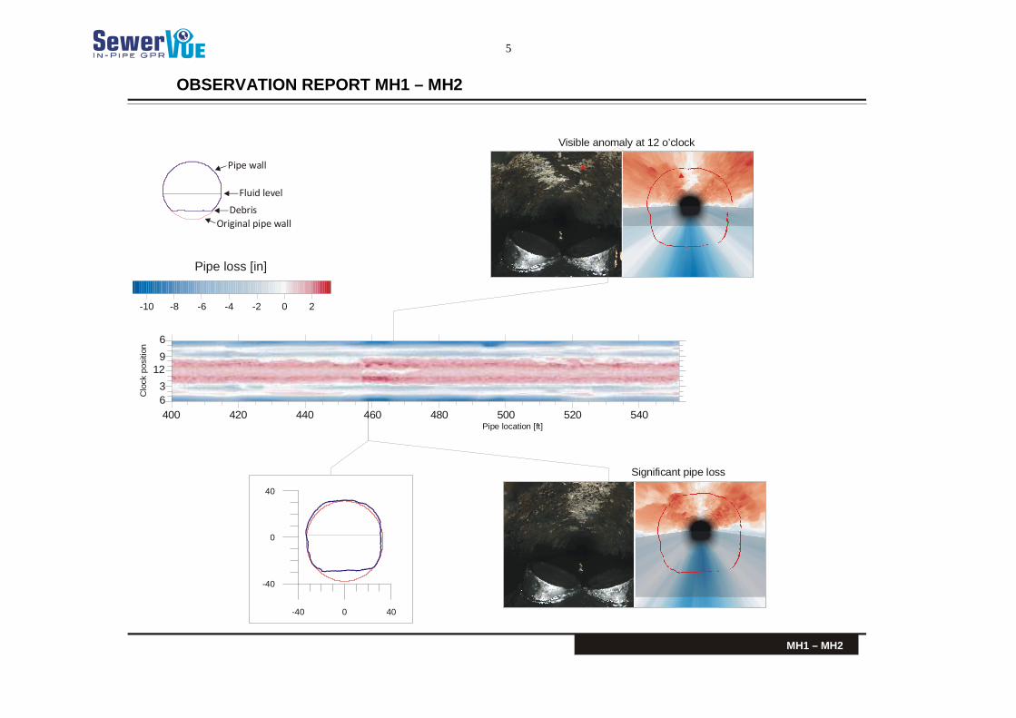
OBSERVATION REPORT MH1 – MH2
MH1 – MH2
Clo
ck p
ositi
on
Pipe location [ft]400 420 440 460 480 500 520 540
3
9
Significant pipe loss
Visible anomaly at 12 o’clock
Fluid level
Debris
Original pipe wall
Pipe wall
Pipe loss [in]
-10 -8 -6 -4 -2 0 2
6
12
6
-40 0 40
-40
0
40

6
DEBRIS GRAPH MH1 – MH2
Clo
ck p
ositi
on
MH1 – MH2
Variation of fluid level
Variation of debris depthmaximum
Pipe diameter
Pipe location [ft]
50 100 150 200 250 300 350 400 450 500 550
3
9
Pipe loss [in]
-10 -8 -6 -4 -2 0 2
Variation of maximum pipe loss
6
12
6
0 40 80 120 160 200 240 280 320 360 400 440 480 520 560
0
20
40
60
80

7
CONTACT DETAILS
Csaba Ekes [email protected]
4650A Dawson St Burnaby
British Columbia V5C 4C3 Canada
888-973-9378
The information contained in this Report is provided for interpretation by suitably qualified civil engineering professionals engaged by the Client. This Report is not intended and must not be taken to be professional civil engineering advice, nor shall it be relied upon as a substitute for professional civil engineering advice.
Interpretation of this Report, evaluation of the pipelines, and any rehabilitation, investigative, cleaning or other decisions are the sole responsibility of the Client.
Certain information contained in this report such as distances and dimensions may incorporate information provided by others. This information may not always be accurate and complete. The Engineer should make their own assessments with regards to such information.


