154
SANITARY SURVEY GUIDANCE MANUAL FOR GROUND WATER SYSTEMS October 2008 EPA 815-R-08-015
SANITARY SURVEY GUIDANCE MANUAL FOR GROUND WATER SYSTEMS
October 2008 EPA 815-R-08-015

Office of Water (4606) EPA 815-R-08-015 October 2008
October 2008 Sanitary Survey i Guidance Manual for Ground Water Systems
DISCLAIMER
This manual is intended to provide information to assist States in conducting sanitary surveys of public water systems subject to the requirements of the Ground Water Rule. The U.S. Environmental Protection Agency believes that a comprehensive sanitary survey is an important part of helping water systems protect public health.
The statutory provisions and EPA regulations described in this document contain legally
binding requirements. This guidance is not a substitute for applicable legal requirements, nor is it a regulation itself. Thus, it does not impose legally-binding requirements on any party, including EPA, States, or the regulated community. While EPA has made every effort to ensure the accuracy of the discussion in this guidance, the obligations of the regulated community are determined by statutes, regulations, or other legally binding requirements. In the event of a conflict between the discussion in this document and any statute or regulation, this document would not be controlling.
Interested parties are free to raise questions and objections to the guidance and the
appropriateness of using it in a particular situation.
Although this manual describes suggestions for complying with GWR requirements, the guidance presented here may not be appropriate for all situations, and alternative approaches may provide satisfactory performance.
Mention of trade names or commercial products does not constitute an EPA endorsement or recommendation for use.
Authorship
This manual was developed under the direction of EPA’s Office of Ground Water and
Drinking Water and was prepared by EPA and the Cadmus Group Inc. Questions regarding this document should be addressed to:
Michael Finn U.S. EPA Office of Ground Water and Drinking Water 1200 Pennsylvania Avenue, N.W. Washington, DC 20460 [email protected] 202-564-5261

October 2008 Sanitary Survey ii Guidance Manual for Ground Water Systems
ACKNOWLEDGMENTS American Water Works Association; Association of State Drinking Water Administrators; Dan Schmelling, U.S. EPA, Washington DC; Kevin Reilly, U.S. EPA, Region II; Steve Allgeier, U.S. EPA, Cincinnati.
October 2008 Sanitary Survey iii Guidance Manual for Ground Water Systems
CONTENTS Exhibits .......................................................................................................................................... vi Acronyms ...................................................................................................................................... vii 1. Introduction and Scope of This Manual .........................................................................1-1
1.1 Ground Water Rule (GWR) Requirements ..........................................................1-2 1.2 Applicability of the GWR Sanitary Survey Requirements ..................................1-7 1.3 Minimum Elements of the Sanitary Survey .........................................................1-8
2. Other Drinking Water Regulations and PWS Requirements ......................................2-1
2.1 Definition of PWS................................................................................................2-1 2.2 Safe Drinking Water Act (SDWA) ......................................................................2-2
2.2.1 National Primary Drinking Water Regulations (40 CFR Part 141) ...............2-2 2.2.2 Ground Water Rule Implementation (40 CFR Part 142) ...............................2-4 2.2.3 Code of Federal Regulations ..........................................................................2-4 2.2.4 Definition of Wholesale and Consecutive Systems .......................................2-4 2.2.5 Source Water Assessment and Protection Program (SWAPP) and Wellhead Protection Program (WHPP) .........................................................2-5 2.2.6 Total Coliform Rule (TCR) ...........................................................................2-5 2.2.7 Lead and Copper Rule ...................................................................................2-5 2.2.8 Stage 1 Disinfectants and Disinfection Byproducts (D/DBPs) ......................2-6 2.2.9 Stage 2 Disinfectants and Disinfection Byproducts (D/DBPs) ......................2-6 2.2.10 Inorganic and Organic Chemicals ..................................................................2-7 2.2.11 Radiological Contaminants ............................................................................2-7
3. Preparing for the Survey ..................................................................................................3-1
3.1 Contact and Location ...........................................................................................3-1 3.2 Planning the Sanitary Survey ...............................................................................3-2
3.2.1 Resources Needed ..........................................................................................3-2 3.2.2 Personal Safety...............................................................................................3-3 3.2.3 Logistics .........................................................................................................3-3
3.3 Inventory of System Facilities .............................................................................3-4 3.4 File Review Elements ..........................................................................................3-6
3.4.1 Previous Sanitary Surveys .............................................................................3-7 3.4.2 Source Water Assessments ............................................................................3-7 3.4.3 Compliance and Enforcement History ...........................................................3-8 3.4.4 Monitoring Plans ............................................................................................3-9 3.4.5 Consumer Confidence Reports (CCR)......................................................... 3-10 3.4.6 Technical, Managerial and Financial Capacity Evaluations ........................ 3-10 3.4.7 Other Required Submittals ........................................................................... 3-10 3.4.8 Total Coliform Rule (TCR) History ............................................................ 3-11 3.4.9 Variances and Exemptions ........................................................................... 3-12 3.4.10 Correspondence............................................................................................ 3-12
4. Field Survey .......................................................................................................................4-1
4.1 Logistics ...............................................................................................................4-2

October 2008 Sanitary Survey iv Guidance Manual for Ground Water Systems
4.2 Sources .................................................................................................................4-3 4.2.1 Well Construction ..........................................................................................4-3
4.2.1.1 Surface Features .................................................................................4-5 4.2.1.2 Subsurface Features ...........................................................................4-9 4.2.1.3 Well Construction and Completion Information ............................. 4-11 4.2.1.4 Typical Defects ................................................................................ 4-11
4.2.2 Potential Sources of Contamination............................................................. 4-12 4.2.2.1 Wellhead Protection Program (WHPP) ........................................... 4-13 4.2.2.2 Source Water Assessment ................................................................ 4-13 4.2.2.3 Abandoned Wells ............................................................................. 4-14
4.2.3 Source Quantity and Capacity ..................................................................... 4-14 4.2.4 Confirm Well Locations .............................................................................. 4-17 4.2.5 Source Water Transmission ......................................................................... 4-17 4.2.6 Site Security ................................................................................................. 4-18 4.2.7 General Housekeeping ................................................................................. 4-19 4.2.8 Cross Connections ....................................................................................... 4-19
4.3 Treatment ........................................................................................................... 4-20 4.3.1 Treatment Plant Schematic/Site Plan ........................................................... 4-21 4.3.2 Capacity of Treatment Facilities .................................................................. 4-22 4.3.3 Chemicals and Chemical Feed Systems ...................................................... 4-23
4.3.3.1 Liquid Chemical Feed Systems ....................................................... 4-23 4.3.3.2 Dry Chemical Feeders (Volumetric and Gravimetric)..................... 4-24
4.3.4 Disinfection .................................................................................................. 4-27 4.3.4.1 Dosage and Residual ........................................................................ 4-27 4.3.4.2 Chlorine and Water .......................................................................... 4-28 4.3.4.3 Gas Chlorination .............................................................................. 4-31 4.3.4.4 Liquid Hypochlorination .................................................................. 4-34 4.3.4.5 Typical Liquid Chlorine System ...................................................... 4-34 4.3.4.6 Typical Defects ................................................................................ 4-37
4.4 Distribution System ........................................................................................... 4-38 4.4.1 Distribution System Mapping ...................................................................... 4-38 4.4.2 Distribution System Pipe Material and Condition ....................................... 4-40 4.4.3 Location and Maintenance of Valves .......................................................... 4-42 4.4.4 Design and Construction Standards ............................................................. 4-44 4.4.5 Maintaining Adequate Pressure ................................................................... 4-45 4.4.6 Response to Water Main Breaks .................................................................. 4-46 4.4.7 Flushing Programs ....................................................................................... 4-47 4.4.8 Water Quality Monitoring............................................................................ 4-47
4.4.8.1 Maintaining a Residual .................................................................... 4-48 4.4.8.2 Bacteriological Quality (TCR) ......................................................... 4-49 4.4.8.3 Other Water Quality Parameters ...................................................... 4-50 4.4.8.4 Customer Complaints....................................................................... 4-50
4.4.9 Cross Connection Control ............................................................................ 4-51 4.5 Finished Water Storage ...................................................................................... 4-53
4.5.1 Storage Facility Inventory............................................................................ 4-54 4.5.2 Capability and Capacity ............................................................................... 4-58
4.5.2.1 Capability ......................................................................................... 4-58 4.5.2.2 Storage Capacity .............................................................................. 4-60
4.5.3 Design and Construction .............................................................................. 4-60

October 2008 Sanitary Survey v Guidance Manual for Ground Water Systems
4.5.4 Site Security ................................................................................................. 4-65 4.6 Pumps ................................................................................................................. 4-66
4.6.1 Typical Pumps ............................................................................................. 4-66 4.6.2 Number and Capacity .................................................................................. 4-70 4.6.3 Routine Maintenance/Lubrication/Exercise ................................................. 4-72 4.6.4 Housing ........................................................................................................ 4-72 4.6.5 Site Security ................................................................................................. 4-72 4.6.6 Cross Connections ....................................................................................... 4-72
4.7 Emergency Power .............................................................................................. 4-73 4.8 Remote Monitoring/Control/Alarms .................................................................. 4-74 4.9 Monitoring/Reporting/Data Verification ........................................................... 4-75 4.10 Water System Management/Operations ............................................................ 4-77
4.10.1 Organization and Management .................................................................... 4-78 4.10.2 Staff Levels .................................................................................................. 4-79 4.10.3 Training ........................................................................................................ 4-80 4.10.4 Revenue........................................................................................................ 4-81 4.10.5 Additional Management Issues .................................................................... 4-82
4.11 Operator Requirements ...................................................................................... 4-82 4.11.1 General Operator Requirements .................................................................. 4-82 4.11.2 Certification Required Based on Size/Treatment ........................................ 4-83
4.12 References .......................................................................................................... 4-83 5. Compiling and Reporting the Sanitary Survey Results ................................................5-1
5.1 Sanitary Survey Report ........................................................................................5-2 5.2 Sanitary Survey Documentation ..........................................................................5-4 5.3 Categorizing the Findings ....................................................................................5-5 5.4 Corrective Action .................................................................................................5-9 5.5 Outstanding Performance ................................................................................... 5-10
6. Report Review and Response ...........................................................................................6-1
6.1 State Actions ........................................................................................................6-1 6.2 Water System Actions..........................................................................................6-3
Appendices Appendix A Evaluating Ground Water Treatment for Ground Water Rule Compliance Appendix B Using Sanitary Surveys to Update State Source Water Protection Programs
October 2008 Sanitary Survey vi Guidance Manual for Ground Water Systems
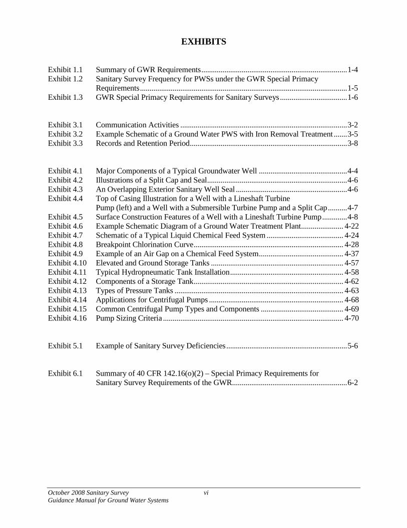
EXHIBITS Exhibit 1.1 Summary of GWR Requirements ............................................................................ 1-4 Exhibit 1.2 Sanitary Survey Frequency for PWSs under the GWR Special Primacy
Requirements ............................................................................................................ 1-5 Exhibit 1.3 GWR Special Primacy Requirements for Sanitary Surveys ................................... 1-6 Exhibit 3.1 Communication Activities ....................................................................................... 3-2 Exhibit 3.2 Example Schematic of a Ground Water PWS with Iron Removal Treatment ....... 3-5 Exhibit 3.3 Records and Retention Period .................................................................................. 3-8 Exhibit 4.1 Major Components of a Typical Groundwater Well .............................................. 4-4 Exhibit 4.2 Illustrations of a Split Cap and Seal ......................................................................... 4-6 Exhibit 4.3 An Overlapping Exterior Sanitary Well Seal .......................................................... 4-6 Exhibit 4.4 Top of Casing Illustration for a Well with a Lineshaft Turbine Pump (left) and a Well with a Submersible Turbine Pump and a Split Cap .......... 4-7 Exhibit 4.5 Surface Construction Features of a Well with a Lineshaft Turbine Pump ............. 4-8 Exhibit 4.6 Example Schematic Diagram of a Ground Water Treatment Plant ...................... 4-22 Exhibit 4.7 Schematic of a Typical Liquid Chemical Feed System ........................................ 4-24 Exhibit 4.8 Breakpoint Chlorination Curve .............................................................................. 4-28 Exhibit 4.9 Example of an Air Gap on a Chemical Feed System ............................................ 4-37 Exhibit 4.10 Elevated and Ground Storage Tanks ..................................................................... 4-57 Exhibit 4.11 Typical Hydropneumatic Tank Installation ........................................................... 4-58 Exhibit 4.12 Components of a Storage Tank .............................................................................. 4-62 Exhibit 4.13 Types of Pressure Tanks ........................................................................................ 4-63 Exhibit 4.14 Applications for Centrifugal Pumps ...................................................................... 4-68 Exhibit 4.15 Common Centrifugal Pump Types and Components ........................................... 4-69 Exhibit 4.16 Pump Sizing Criteria .............................................................................................. 4-70 Exhibit 5.1 Example of Sanitary Survey Deficiencies ............................................................... 5-6 Exhibit 6.1 Summary of 40 CFR 142.16(o)(2) – Special Primacy Requirements for Sanitary Survey Requirements of the GWR ............................................................ 6-2

October 2008 Sanitary Survey vii Guidance Manual for Ground Water Systems
ACRONYMS
ANSI/NSF American National Standards Institute/National Sanitation Foundation ASME American Society of Mechanical Engineers AWWA American Water Works Association AwwaRF American Water Works Association Research Foundation BFP Backflow Preventer CCR Consumer Confidence Report CFR Code of Federal Regulations CT Concentration of Residual Disinfectant multiplied by Time of Water Contact
(Detention Time) CWS Community Water System DBP Disinfection Byproduct D/DBP Disinfectants/Disinfection Byproducts DHS Department of Health Services DOT Department of Transportation EPA The United States Environmental Protection Agency ETV Environmental Technology Verification GAC Granular Activated Carbon GIS Geographic Information System GLUMRB Great Lakes Upper Mississippi River Board GPS Global Positioning System GREP Generally Recommended Engineering Practice GWR Ground Water Rule GWUDI Ground Water Under the Direct Influence of Surface Water HAA5 Haloacetic Acids HDPE High-density Polyethylene HPC Heterotrophic Plate Count HSA Hydrogeologic Sensitivity Assessment IDSE Initial Distribution System Evaluation IESWTR Interim Enhanced Surface Water Treatment Rule LRAA Locational Running Annual Average MCL Maximum Contaminant Level M-DBP Microbial-Disinfectants/Disinfection Byproducts MRDL Maximum Residual Disinfectant Level MWCO Molecular Weight Cut Off NPDWR National Primary Drinking Water Regulations NSF National Sanitation Foundation NTNCWS Non-transient Non-community Water System O&M Operation and Maintenance OSHA Occupational Safety and Health Administration OWQP Optimal Water Quality Parameter

October 2008 Sanitary Survey viii Guidance Manual for Ground Water Systems
PB Polybutylene PE Polyethylene PVC Polyvinyl Chloride PWS Public Water System RPZ Reduced Pressure Zone SCADA Supervisory Control and Data Acquisition SDWA Safe Drinking Water Act SOC Synthetic Organic Contaminant SOP Standard Operating Procedure SWAPP Source Water Assessment and Protection Program SWTR Surface Water Treatment Rule TCR Total Coliform Rule TDT Theoretical Detention Time THM Trihalomethane TNRCC Texas Natural Resource Conservation Commission TNCWS Transient Non-community Water System TTHM Total Trihalomethane UFTREEO University of Florida Training, Research, and Education for Environmental
Occupations UL Underwriters Laboratories USGS United States Geological Survey UV Ultraviolet Light VOC Volatile Organic Contaminant WFI Water Facilities Inventory WHPA Wellhead Protection Area WHPP Wellhead Protection Program

October 2008 Sanitary Survey 1-1 Guidance Manual for Ground Water Systems
1. Introduction and Scope of This Manual
This manual provides guidance on how to conduct a sanitary survey of a Public Water System (PWS) that is served by ground water. A sound sanitary survey program is an essential element of an effective State drinking water program. Sanitary surveys are a proactive public health measure that can identify deficiencies in PWSs before any contamination of the public water supply occurs.
Sanitary surveys enable States to provide a comprehensive and accurate review of the components of water systems, to assess the operating conditions and adequacy of the water system, and to determine if past recommendations have been implemented effectively. The purpose of the sanitary survey is to evaluate and document the capabilities of the water system's sources, treatment, storage, distribution network, operation and maintenance, and overall management to ensure the provision of safe water. In addition, sanitary surveys provide an opportunity for States to visit the water system and educate operators about proper monitoring and sampling procedures and to provide technical assistance. This guidance manual identifies assessment criteria to evaluate sanitary risks in a typical water system. The manual also describes how to identify significant deficiencies that are causing, or have the potential to cause, the introduction of contamination into the water delivered to consumers and, therefore, require corrective actions.
State agencies should use this manual as a tool to ensure that sanitary surveys are
comprehensive, well documented, and meet the primacy requirements. PWS owners and operators will find hands-on information on operation and management of their drinking water systems and drinking water well sources. The manual also helps surveyors understand how each set of Safe Drinking Water Act (SDWA) regulations applies to sanitary surveys.
The overall structure of the guidance manual centers on the four principal stages of a
sanitary survey: planning a sanitary survey; conducting the onsite survey; compiling a sanitary survey report; and performing follow-up activities including responding to significant deficiencies. The manual is organized as follows:
• Chapter 1 – Introduction and Scope of This Manual. This chapter provides background information, explains the Ground Water Rule (GWR) requirements for sanitary surveys, and discusses the minimum elements of a sanitary survey.
• Chapter 2 – Other Drinking Water Regulations and PWS Requirements. This chapter provides information on the regulatory context for sanitary surveys.
As used in this guidance, “State” refers to the agency of the State or Tribal government that has jurisdiction over public water systems. During any period when a State or Tribal government does not have primacy enforcement responsibility pursuant to section 1413 of the Safe Drinking Water Act, the term “State” means the Regional Administrator, U.S. Environmental Protection Agency.
October 2008 Sanitary Survey 1-2 Guidance Manual for Ground Water Systems
• Chapter 3 – Preparing for the Survey. This chapter provides guidance as to tasks that should be carried out in the office before a surveyor conducts the field component of the sanitary survey.
• Chapter 4 – Field Survey. This chapter discusses each of the eight elements of a sanitary survey that meets the requirements of the GWR. The chapter explains each element’s importance for an effective sanitary survey and presents general guidelines (assessment criteria) for evaluating important components of each element. Discussions about each element identify the components of high priority that may be considered significant deficiencies.
• Chapter 5 – Compiling and Reporting the Sanitary Survey Results. This chapter provides guidelines for compiling and reporting the sanitary survey results as well as suggestions for keeping adequate documentation of the sanitary survey.
• Chapter 6 – Report Review and Response. This chapter describes the follow-up actions that should be taken by the water system operator and the State in response to the findings of a sanitary survey, including those actions that must be taken to correct any identified deficiencies.
1.1 Ground Water Rule (GWR) Requirements The GWR applies to all PWSs1 that serve ground water, including consecutive systems that serve ground water from a wholesale PWS. The GWR does not apply to PWSs that combine all their ground water sources with surface water or ground water under the direct influence of surface water prior to treatment that meets the requirements for surface water supplies (40 CFR Subpart H).
Requirements of the GWR include:
• System sanitary surveys conducted by the State with minimum scope and frequency and identification of significant deficiencies;
• Triggered source water microbial monitoring by systems that do not provide 4-log treatment of viruses for their ground water sources and have a Total Coliform Rule (TCR)-positive within the system’s distribution system;
• Corrective action by any system with significant deficiencies or fecal indicator positive source water samples; and
• Compliance monitoring for systems that provide 4-log treatment of viruses for their ground water sources.
The GWR also requires ground water systems, if directed by the State, to conduct
assessment source water monitoring of their ground water sources. The United States
1 A PWS serves at least 15 service connections or regularly serves at least 25 people at least 60 days per year.

October 2008 Sanitary Survey 1-3 Guidance Manual for Ground Water Systems
Environmental Protection Agency (EPA) recommends that this assessment monitoring consist of 12 source water samples analyzed for E.Coli, coliphage, or enterococci, as specified by the State. EPA also recommends hydrogeologic sensitivity assessments (HSAs) for ground water systems drawing from aquifers susceptible to fecal contamination as a basis for assessment source water monitoring. If the State chooses to perform HSAs, the GWR requires systems to provide the State with available information necessary for the State to conduct the HSAs.
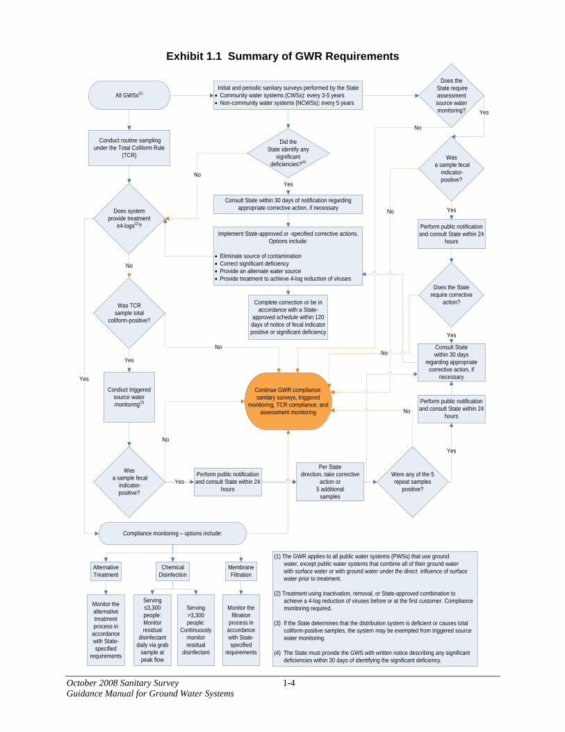
A summary of the GWR’s requirements is illustrated in Exhibit 1.1.
October 2008 Sanitary Survey 1-4 Guidance Manual for Ground Water Systems
Exhibit 1.1 Summary of GWR Requirements
All GWSs(1)Initial and periodic sanitary surveys performed by the State
• Community water systems (CWSs): every 3-5 years• Non-community water systems (NCWSs): every 5 years
Yes
Was a sample fecal
indicator-positive?
Complete correction or be in accordance with a State-
approved schedule within 120 days of notice of fecal indicator positive or significant deficiency
Conduct routine sampling under the Total Coliform Rule
(TCR)
Implement State-approved or -specified corrective actions. Options include:
• Eliminate source of contamination• Correct significant deficiency• Provide an alternate water source • Provide treatment to achieve 4-log reduction of viruses
Continue GWR compliance: sanitary surveys, triggered
monitoring, TCR compliance, and assessment monitoring
No
YesWere any of the 5 repeat samples
positive?
No
Yes
Compliance monitoring – options include:
Serving >3,300 people:
Continuously monitor residual
disinfectant
Serving ≤3,300 people:Monitor residual
disinfectant daily via grab
sample at peak flow
Chemical Disinfection
Alternative Treatment
Monitor the filtration
process in accordance with State-specified
requirements
Membrane Filtration
Monitor the alternative treatment process in
accordance with State-specified
requirements
No
Yes
No
Consult State within 30 days
regarding appropriate corrective action, if
necessary
Perform public notification and consult State within 24
hours
Was TCRsample total
coliform-positive?
Does system provide treatment
≥4-logs(2)?
Did the State identify any
significant deficiencies?(4)
Does the State require assessment source water monitoring?
No
Was a sample fecal
indicator-positive?
Consult State within 30 days of notification regarding appropriate corrective action, if necessary
Yes
Does the State require corrective
action?
Yes
No
Perform public notification and consult State within 24
hours
Yes
Perform public notification and consult State within 24
hoursYes
Conduct triggered source water monitoring(3)
No
No
Yes
(1) The GWR applies to all public water systems (PWSs) that use ground water, except public water systems that combine all of their ground water with surface water or with ground water under the direct influence of surface water prior to treatment.
(2) Treatment using inactivation, removal, or State-approved combination to achieve a 4-log reduction of viruses before or at the first customer. Compliance monitoring required.
(3) If the State determines that the distribution system is deficient or causes total coliform-positive samples, the system may be exempted from triggered source water monitoring.
(4) The State must provide the GWS with written notice describing any significant deficiencies within 30 days of identifying the significant deficiency.
Per Statedirection, take corrective
action or 5 additional
samples

October 2008 Sanitary Survey 1-5 Guidance Manual for Ground Water Systems
The special primacy (40 CFR 142.16) requirements of the GWR require sanitary surveys every three years for community ground water systems and every five years for non-community ground water systems. This is consistent with the 1998 Interim Enhanced Surface Water Treatment Rule (IESWTR) sanitary survey requirements for surface water systems. The survey frequency is shown in Exhibit 1.2. Exhibit 1.2 Sanitary Survey Frequency for PWSs under the GWR Special Primacy
Requirements
System Type Minimum Frequency of Surveys Community water system At least every 3 years If allowed by the State, community water system with outstanding performance based on prior sanitary surveys OR treating to 4-log treatment of viruses
At least every 5 years
Non-community water system (both non-transient and transient non-community)
At least every 5 years
The key components of the GWR’s sanitary survey requirements include:
• A special primacy requirement that requires the State to conduct sanitary surveys that address the minimum eight elements for all ground water systems.
• A special primacy requirement that the State must have authority to enforce corrective action requirements.
• A special primacy requirement that the State must provide written notice of all significant deficiencies (e.g., those that require corrective action) to the system within 30 days of identification of the deficiencies.
• Systems must consult with the State within 30 days and take corrective action for any significant deficiencies no later than 120 days after receiving written notification of such deficiencies, or be in compliance with a State-approved schedule and plan for correcting these deficiencies within the same 120 day period.
Once a ground water system has been identified as having significant deficiencies, it must
do one or more of the following:
• Eliminate the source of contamination;
• Correct the significant deficiency;
• Provide an alternate source of water; or
October 2008 Sanitary Survey 1-6Guidance Manual for Ground Water Systems
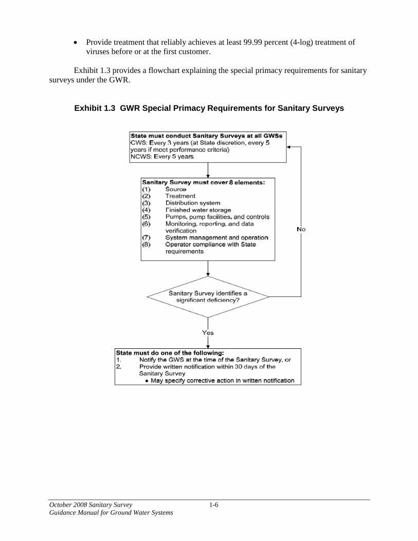
• Provide treatment that reliably achieves at least 99.99 percent (4-log) treatment ofviruses before or at the first customer.
Exhibit 1.3 provides a flowchart explaining the special primacy requirements for sanitary surveys under the GWR.
Exhibit 1.3 GWR Special Primacy Requirements for Sanitary Surveys

October 2008 Sanitary Survey 1-7Guidance Manual for Ground Water Systems
Community water systems that are classified as having outstanding performance are eligible for having sanitary surveys conducted less frequently than other community systems. Under the GWR special primacy requirements, community water systems must have a sanitary survey performed by the State at least once every three years with some exceptions. If the State determines that a community system either provides 4-log treatment of viruses or has shown outstanding performance, the survey frequency may be reduced to at least once every five years.
If the State will reduce the frequency of sanitary surveys for community ground water systems, the primacy application must include how the State will determine that a system has an outstanding performance record. A State should have defined outstanding performance and established certain specifications for determining outstanding performance. To determine if a system has outstanding performance, the surveyor should review the report from the system’s previous sanitary survey to see if the system was considered to have outstanding performance at that time. During a sanitary survey, the surveyor should review files and field results before making a recommendation in the sanitary survey report whether the system’s performance should remain or become outstanding. If the State includes information on outstanding performance designations in a tracking database, the surveyor should check the system’s listing in the database. The surveyor should also examine the State’s records on the facility collected since the last sanitary survey. The records of interest will depend upon the State’s criteria for outstanding performance but may include: monitoring data, violation records, and notifications of changes to the physical facility or the operator personnel. This information will help the surveyor to determine if there are any changes in performance since the previous survey that indicate the system no longer satisfies the State’s definition of outstanding performance.
1.2 Applicability of the GWR Sanitary Survey Requirements
The GWR applies to all PWSs serving ground water except for systems that combine all their ground water sources with surface water or with ground water under the direct influence of surface water prior to treatment that meets the requirements for surface water sources (40 CFR Subparts H, P, T, and W). Under the GWR, sanitary surveys must address the minimum eight elements and must be conducted with a minimum frequency. The GWR sanitary survey scope and frequency requirements are the same as the sanitary survey scope and frequency requirements for surface water systems. The GWR requires that systems with significant deficiencies identified during sanitary surveys, or during other State activities, must correct significant deficiencies within 120 days or be in compliance with a State-approved schedule for correction. A failure to correct significant deficiencies is a violation of the treatment technique requirements of the GWR. GWR treatment technique violations require the system to conduct public notice and systems may be subject to State or Federal enforcement actions.
Sanitary survey resources can be found online. Available resources include:
• Sanitary Survey Training for Inspecting Small Water Systems, location to bedetermined;
• Sanitary Survey Fundamentals Prep Course, available athttps://www.msun.edu/grants/metc/othertraining/cdrom.asp;

October 2008 Sanitary Survey 1-8 Guidance Manual for Ground Water Systems
• Electronic Sanitary Survey;
• Learner’s Guide: How to Conduct a Sanitary Survey of Small Water Systems, available at http://neshta.org/product/sanitary-survey-inspector-training-course-learners-guide/;
• Drinking Water Inspector’s Field References for Small Ground Water Systems and Small Surface Water Systems, location to be determined;
• Sanitary Survey Inspection “Before You Begin” DVD, available at http://www.worldcat.org/title/sanitary-survey-inspection-before-you-begin/oclc/59134380;
• Learner’s Guide to Security Considerations for Small Drinking Water Systems When Performing a Sanitary Survey, available at http://neshta.org/product/learners-guide-to-security-considerations-for-small-drinking-water-systems/;
• Troubleshooting Guide for Small Ground Water Systems, available at https://permanent.access.gpo.gov/websites/epagov/www.epa.gov/safewater/dwa/pdfs/gw-tsg.pdf;
• Cross-Connection Control Manual; and
• EPA Guidance Manual: Conducting Sanitary Surveys of Public Water Systems – Surface Water and GWUDI.
1.3 Minimum Elements of the Sanitary Survey
The special primacy requirements of the GWR require States to conduct sanitary surveys that address the applicable eight elements described previously. This document is intended to provide comprehensive guidance to assist States in completing sanitary surveys that address the applicable eight elements. The special primacy requirements allow States to use a phased approach to meet the sanitary survey requirements if all the applicable eight elements are evaluated within the required sanitary survey interval. This phased approach allows States to use existing oversight and review programs to address one or more of the required eight elements. Using the phased approach, States could complete reviews of some of the eight elements during onsite reviews of systems and complete reviews of the remaining applicable elements through other State programs. Examples of State programs that could address the required elements include:

October 2008 Sanitary Survey 1-9 Guidance Manual for Ground Water Systems
• Ongoing reporting (e.g., monthly, annual) of treatment performance or water quality monitoring;
• Plan review and permit revision;
• Ongoing compliance verification and data reviews;
• Ongoing TMF capacity assessments; and
• Operator certification renewal programs.
October 2008 Sanitary Survey 2-1 Guidance Manual for Ground Water Systems
2. Other Drinking Water Regulations and PWS Requirements
In addition to specifying maximum contaminant levels (MCLs), the Federal drinking water regulations address sampling location, frequency, recordkeeping and other requirements that should be evaluated during a sanitary survey. This section provides the basic information for surveyors to determine if a water system is a PWS subject to EPA regulations. If so, surveyors should be able to recognize requirements from various provisions of the drinking water regulations.
2.1 Definition of PWS
PWSs are defined as systems for providing water for human consumption through pipes or other constructed conveyances, if such systems have at least 15 service connections or regularly serve at least 25 people at least 60 days a year. A system includes any collection, treatment, storage, and distribution facilities under control of the operator of such system and used primarily in connection with such a system, and any collection or treatment facilities not under such control that are used primarily in connection with such a system.
Important field determinations made during a sanitary survey are:
• The number of people served by the system;
• The number of service connections; • The type of consumer served (e.g., residents, employees, visitors); and
• Whether service is provided for at least 60 days a year.
This information determines whether a system meets the definition of a PWS in SDWA
and whether it is subject to the national primary drinking water regulations (NPDWR).
Although the NPDWR apply to all PWSs, the regulations make a distinction between community and non-community systems. A further distinction is made between transient and non-transient non-community systems.
Community water systems serve a residential population of at least 25 people or 15 service connections on a year-round basis. Users of community systems are likely to be exposed to any contaminants in the water supply over an extended time period and are thus subject to both acute and chronic health effects.
Non-community systems are either transient or non-transient systems. Non-transient non-community water systems (NTNCWS) serve at least 25 of the same persons at least 6 months per year on a regular basis. These systems can expose users to drinking water contaminants over an extended time period (subjecting users to risks of both acute and chronic health effects), similar to community systems. Schools, factories and office parks would fall under this definition. Transient non-community water systems (TNCWS) serve short-term users. As a result, the users

October 2008 Sanitary Survey 2-2 Guidance Manual for Ground Water Systems
are exposed to any drinking water contaminants only briefly. Users are subject to experiencing acute health effects. Examples are restaurants, gas stations, hotels, and campgrounds.
These distinctions and others, such as the water source and population served, are important because States may regulate these systems differently. A surveyor needs to know the characteristics of a system to know whether a system is properly classified and, therefore, which regulations are applicable. The population served also determines sampling frequency in a number of regulations, including the TCR, Lead and Copper Rule, Stage 1 and Stage 2 Disinfectants and Disinfection Byproducts (D/DBP) Rules, and Phase II and V inorganic and organic chemical monitoring.
Most water system operators will know how many individual service connections they have within their systems but not necessarily the population served by the system. Some States will use a factor multiplied by the number of service connections to estimate population. During the survey, the surveyor should determine if the State records on population and number of service connections are up-to-date. Further evaluation will be needed to determine if changes in population will affect the system’s status relative to any SDWA requirements. 2.2 Safe Drinking Water Act (SDWA)
Congress enacted the SDWA in 1974. The Act was intended to ensure the delivery of safe drinking water by PWSs and to protect ground water sources from contamination.
In 1986, Amendments to the SDWA were signed into law. These Amendments greatly expanded the number and type of contaminants to be regulated in drinking water, as well as strengthened EPA’s enforcement authority. The passage of these Amendments was the result of heightened concern about the potential contamination of public water supplies by toxic chemicals and an increase in the number of waterborne disease outbreaks caused by microbiological contaminants.
In 1996, Congress again amended the SDWA. The new law for the first time provides for State revolving loan funds to improve water systems. It also requires EPA to base regulations on risk assessment and cost-benefit considerations. The new law requires EPA to identify the best treatment technologies for various sizes of systems and establish guidelines for operator certification. Monitoring relief is provided for small systems. Source water protection and consumer confidence reports are also a part of the new law.
Brief summaries of important drinking water regulations that form the basis for sanitary surveys of ground water systems are provided in this section. 2.2.1 National Primary Drinking Water Regulations (40 CFR Part 141)
Under the SDWA, EPA establishes drinking water regulations for contaminants known to occur or potentially occur in drinking water that may have an adverse effect on public health. These regulations are known as the national primary drinking water regulations (NPDWR) and include MCLs or treatment techniques for over 100 contaminants. Monitoring and testing procedures also are specified. As mentioned above, the NPDWRs apply to all PWSs.

October 2008 Sanitary Survey 2-3 Guidance Manual for Ground Water Systems
Congress intended SDWA requirements to be implemented primarily by the States.
Therefore, the SDWA requires EPA to define the requirements for allowing States to implement and enforce State regulations in lieu of the Federal regulations. State regulations must be at least as stringent as the Federal regulations; however, they may also be more stringent. When a State’s program has been approved by EPA, the State is granted primary enforcement authority (“primacy”) for its drinking water program. Primacy requirements are codified in 40 CFR Part 142, NPDWRs Implementation. EPA may grant a State primary enforcement authority when the Administrator of EPA determines that a State has met the following requirements:
• Defining a PWS consistent with the definition in the SDWA;
• Having adequate enforcement authority and procedures;
• Maintaining an inventory of PWSs;
• Having a systematic program for conducting sanitary surveys of PWSs with priority given to systems not in compliance with the NPDWRs;
• Having a program to certify laboratories that will analyze water samples;
• Having a certified laboratory that will serve as the State’s principal laboratory;
• Having a program to review the design and construction of new or modified systems;
• Having adequate recordkeeping and reporting requirements;
• Having an adequate plan to provide for safe drinking water in emergencies; and
• Having variance and exemption requirements as stringent as EPA’s if the State chooses to allow variances or exemptions.
PWSs may be subject to State as well as Federal drinking water regulations. Therefore,
whenever a Federal regulation is cited in this document, the State primacy agency surveyor needs to be aware of the equivalent State regulation as well as any additional State requirements if allowed under State law.
National secondary drinking water regulations control contaminants in drinking water
that primarily affect the aesthetic qualities relating to the public acceptance of drinking water. At considerably higher concentrations of these contaminants, health implications may also exist as well as aesthetic degradation. The regulations are not federally enforceable but are intended as guidelines for States.
October 2008 Sanitary Survey 2-4 Guidance Manual for Ground Water Systems
2.2.2 Ground Water Rule Implementation (40 CFR Part 142)
States are required by 40 CFR Part 142.15(c)(7) to report the month and year the most recent sanitary survey was completed. Similar reports are required for any corrective actions completed under the GWR and for any ground water PWSs providing 4-log treatment of viruses.
Section 142.16, Special Primacy Requirements, ensures that States have the legal authority to enforce and implement the GWR. States describe how they will implement a sanitary survey program and the other required elements in 40 CFR Part 141. States must conduct sanitary surveys for all ground water PWSs with a minimum frequency and scope. The first sanitary survey for community water systems must be completed six years after promulgation of the final rule, or eight years after promulgation of the final rule for non-community systems. Subsequent surveys must be conducted every three or five years, for community systems and non-community water systems, respectively. The GWR allows a five-year frequency for sanitary surveys for community PWSs that provide 4-log treatment of viruses or have an outstanding performance record as determined by the State. 2.2.3 Code of Federal Regulations
All final EPA regulations are published (or “promulgated”) in the Federal Register. Federal regulations are compiled annually and codified in the Code of Federal Regulations (CFR). EPA’s regulations are found in Title 40 of the CFR (40 CFR). NPDWRs are incorporated or codified in 40 CFR Part 141, which is divided into subparts and sections for specific regulatory provisions. For example, coliform monitoring requirements are found in section 21 of Part 141 (40 CFR 141.21). The CFR is available from the Government Printing Office in Washington, D.C., and EPA’s regulations can be accessed and downloaded from its Web site (http://www.ecfr.gov/cgi-bin/text-idx?SID=3a12271a7a516b0c19f675e25de5ed5d&mc=true&node=pt40.25.141&rgn=div5). The EPA Drinking Water Hotline (800-426-4791) provides another easily accessible source of information on SDWA regulations. 2.2.4 Definition of Wholesale and Consecutive Systems The Stage 2 Disinfectants and Disinfection Byproducts Rule (Stage 2 D/DBP Rule ) added definitions of wholesale systems and consecutive systems as well as a definition of finished water to section 2 of Part 141 (40 CFR 141.2). The Stage 2 D/DBP Rule includes specific requirements for both wholesale and consecutive systems including monitoring requirements and compliance with the Stage 2 D/DBP Rule’s Maximum Contaminant Levels (MCLs). The GWR includes specific requirements for both consecutive systems and wholesale systems that serve ground water. The GWR requirements include source water monitoring and notification requirements for wholesale systems serving ground water and consecutive systems with their own ground water sources as well as notification requirements for consecutive systems serving only ground water supplied by a wholesale system.
October 2008 Sanitary Survey 2-5 Guidance Manual for Ground Water Systems
2.2.5 Source Water Assessment and Protection Program (SWAPP) and Wellhead Protection Program (WHPP)
Section 1453 of the SDWA is a requirement for States to develop and implement Source Water Assessment and Protection Programs (SWAPPs). The SWAPP must delineate the source water areas for all PWSs in the State, identify the potential sources of contaminants within the areas, and determine the susceptibility of the water systems to the contaminants. States are also required to develop WHPPs under Section 1428 of the 1986 Amendments to the SDWA. State WHPPs provide guidelines and a framework for the development of local, system-based WHPPs. Many systems have used these guidelines to develop their own WHPP to address local water protection concerns. 2.2.6 Total Coliform Rule (TCR)
The TCR applies to all PWSs. The sanitary survey requirements of the TCR have been replaced by newer requirements of the IESWTR (for systems served by surface water or ground water under the direct influence of surface water) and the GWR (for systems served by ground water).
The TCR requires that a water system have a written sample siting plan that is subject to State review and revision. The surveyor should verify that there is an approved plan that is being utilized. The surveyor should also evaluate the plan to determine if it is currently meeting the requirements of the TCR. The rule requires collecting samples “that are representative of water throughout the distribution system.” The rule also contains a table that shows the minimum number of samples required based on population served. In reviewing the sample siting plan, the surveyor should evaluate whether samples being collected are “representative” and address issues of concern in the distribution system, or whether the sample siting plan needs to be revised. Some issues to be concerned with are short chlorine contact time to first customer, dead ends, long residence time in the system, multiple sources, storage tanks, areas of low pressure, biofilm, and cross- connections.
2.2.7 Lead and Copper Rule
The Lead and Copper Rule requires community water systems and NTCWSs to collect tap water samples to determine lead and copper levels (40 CFR 141.80-.90). The Lead and Copper Rule Minor Revisions of April 2000 modified some of the original Lead and Copper Rule of 1991. Large water systems (serving >50,000) are required to optimize corrosion control. Small and medium water systems (serving ≤ 50,000) that exceed action levels are required to optimize corrosion control. Surveyors reviewing PWSs required to optimize corrosion control should refer to the Lead and Copper Rule requirements for determining compliance with optimized corrosion control. EPA has also issued guidance entitled How to Determine Compliance with Optimal Water Quality Parameters as Revised by the Lead and Copper Rule Minor Revisions (February 2001). It describes how surveyors determine compliance with the optimal water quality parameter (OWQP) ranges or minimums. Surveyors should also refer to their State’s policy on OWQP monitoring.
October 2008 Sanitary Survey 2-6 Guidance Manual for Ground Water Systems
A surveyor should verify that the system has completed a site sampling plan in compliance with sampling location requirements and is monitoring in accordance with that plan with the required frequency, number and location of samples. Systems using groundwater may reduce source water sampling for the Lead and Copper Rule to once in every nine-year compliance cycle under certain conditions (40 CFR Section 141.88(e), and the surveyor should verify these conditions are still being met. 2.2.8 Stage 1 Disinfectants and Disinfection Byproducts (D/DBPs)
40 CFR Part 141, Subpart L, Disinfectant Residuals, Disinfection Byproducts (DBPs), and DBP Precursors, provides requirements for all community water systems and NTNCWSs that add a chemical disinfectant to their water. Portions of Subpart L also apply to TNCWS that use chlorine dioxide. Components of Subpart L that surveyors must be aware of include:
• MCLs for disinfection by-products including total trihalomethanes (TTHMs), haloacetic acids (HAA5), bromate, and chlorite;
• Maximum residual disinfectant levels for chlorine, chloramines, and chlorine dioxide;
• Monitoring plan requirements; and
• Enhanced coagulation and enhanced softening requirements to address DBP precursors for Subpart H systems with conventional or softening plants.
It should be noted that each system affected by this rule must develop and implement a
monitoring plan. The system must then maintain the monitoring plan and make it available for inspection by the State and general public (systems serving more than 3,000 people must submit their plans to the State). The surveyor should review the monitoring plan while performing the sanitary survey.
2.2.9 Stage 2 Disinfectants and Disinfection Byproducts (D/DBPs)
The Stage 2 D/DBP Rule provides requirements for:
• Community water systems that use a primary or residual disinfectant other than ultraviolet light or deliver water that has been treated with primary or residual disinfectant other than ultraviolet light.
• NTNCWSs that use a primary or residual disinfectant other than ultraviolet light or deliver water that has been treated with primary or residual disinfectant other than ultraviolet light.
The Stage 2 D/DBP Rule requires these systems to meet MCLs as an average at each compliance monitoring location (instead of as a system-wide average as in Stage 1 D/DBP) for two groups of DBPs, TTHM and HAA5.

October 2008 Sanitary Survey 2-7 Guidance Manual for Ground Water Systems
Under the Stage 2 D/DBP rule, most systems will conduct an evaluation of their distribution systems, known as an Initial Distribution System Evaluation (IDSE), to identify the locations with high DBP concentrations. These locations will then be used by the systems as the sampling sites for Stage 2 D/DBP rule compliance monitoring.
Compliance with the MCLs for two groups of DBPs will be calculated for each
monitoring location in the distribution system. This approach, referred to as the locational running annual average (LRAA), differs from Stage 1 D/DBP requirements, which determine compliance by calculating the running annual average of samples from all monitoring locations across the system.
The Stage 2 D/DBP rule also requires each system to determine if they have exceeded an
operational evaluation level, which is identified using their compliance monitoring results. The operational evaluation level provides an early warning of possible future MCL violations, which allows the system to take proactive steps to remain in compliance. A system that exceeds an operational evaluation level is required to review their operational practices and submit a report to their State that identifies actions that may be taken to mitigate future high DBP levels, particularly those that may jeopardize their compliance with the DBP MCLs.
The compliance schedule for Stage 2 D/DBP requirements is based on system size and
sources used (ground water or surface water). The surveyor should verify that the system is conducting compliance monitoring according to an approved plan, and that the system has met the requirements for operational evaluations.
2.2.10 Inorganic and Organic Chemicals
Monitoring requirements for inorganic and organic chemicals are contained in 40 CFR 141.23 and 40 CFR 141.24, respectively. For both groups of contaminants, ground water system samples are required at each entry point to the distribution system that is representative of each well after treatment. Surveyors should verify that all sources are appropriately monitored at the entry point(s). If systems have detected inorganic or organic chemicals, the surveyor should verify that monitoring frequency is appropriate and review any monitoring waivers. 2.2.11 Radiological Contaminants Monitoring requirements for radionuclides are contained in 40 CFR 141.66. For this group of contaminants, community ground water systems are required to monitor at each entry point to the distribution system that is representative of all sources being used under normal operating conditions. Surveyors should verify that all sources are appropriately monitored at the entry point(s).


October 2008 Sanitary Survey 3-1 Guidance Manual for Ground Water Systems
3. Preparing for the Survey
In order to conduct an effective and efficient sanitary survey, the surveyor should organize and plan the effort well. Many critical steps are required, beginning with the first phone call to arrange the onsite survey and ending with the documentation and/or verification of correction of sanitary defects. The survey should be viewed as a cooperative partnership between the primacy agency and the water purveyor, as both organizations share a common goal of providing safe drinking water to the public. 3.1 Contact and Location
The surveyor should contact the water system owner or operator to explain the purpose of the sanitary survey; schedule a meeting location, date, and time when key personnel will be available; and discuss any action that needs to be taken by the water system in preparation for the survey. Telephone contact followed by a short follow-up notification letter is recommended, with sufficient time for system personnel to respond to the notice. If the surveyor must change the schedule, it must be done at the earliest possible time.
Coordination and communication between the surveyor and the primacy agency, local health department, and water system management and operating personnel are essential in preparing for a sanitary survey. The surveyor needs to work with each of these entities to be properly prepared for the sanitary survey. Some of the information the surveyor should exchange with each of these entities is listed in Exhibit 3.1.
October 2008 Sanitary Survey 3-2Guidance Manual for Ground Water Systems
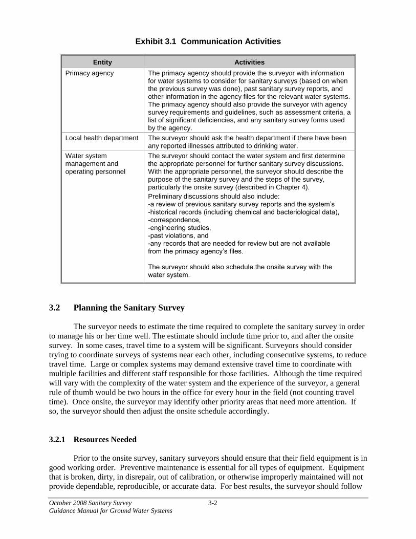
Exhibit 3.1 Communication Activities
Entity Activities Primacy agency The primacy agency should provide the surveyor with information
for water systems to consider for sanitary surveys (based on when the previous survey was done), past sanitary survey reports, and other information in the agency files for the relevant water systems. The primacy agency should also provide the surveyor with agency survey requirements and guidelines, such as assessment criteria, a list of significant deficiencies, and any sanitary survey forms used by the agency.
Local health department The surveyor should ask the health department if there have been any reported illnesses attributed to drinking water.
Water system management and operating personnel
The surveyor should contact the water system and first determine the appropriate personnel for further sanitary survey discussions. With the appropriate personnel, the surveyor should describe the purpose of the sanitary survey and the steps of the survey, particularly the onsite survey (described in Chapter 4). Preliminary discussions should also include: -a review of previous sanitary survey reports and the system’s -historical records (including chemical and bacteriological data), -correspondence,-engineering studies, -past violations, and-any records that are needed for review but are not available from the primacy agency’s files.
The surveyor should also schedule the onsite survey with the water system.
3.2 Planning the Sanitary Survey
The surveyor needs to estimate the time required to complete the sanitary survey in order to manage his or her time well. The estimate should include time prior to, and after the onsite survey. In some cases, travel time to a system will be significant. Surveyors should consider trying to coordinate surveys of systems near each other, including consecutive systems, to reduce travel time. Large or complex systems may demand extensive travel time to coordinate with multiple facilities and different staff responsible for those facilities. Although the time required will vary with the complexity of the water system and the experience of the surveyor, a general rule of thumb would be two hours in the office for every hour in the field (not counting travel time). Once onsite, the surveyor may identify other priority areas that need more attention. If so, the surveyor should then adjust the onsite schedule accordingly.
3.2.1 Resources Needed
Prior to the onsite survey, sanitary surveyors should ensure that their field equipment is in good working order. Preventive maintenance is essential for all types of equipment. Equipment that is broken, dirty, in disrepair, out of calibration, or otherwise improperly maintained will not provide dependable, reproducible, or accurate data. For best results, the surveyor should follow

October 2008 Sanitary Survey 3-3Guidance Manual for Ground Water Systems
the manufacturer’s specifications for preventive maintenance. The surveyor also should check expiration dates and keep up with and use current standard testing procedures and calibration methods. Recommended types of field equipment include but are not limited to:
• PDA, PC, or checklists used for recording results and findings;
• Hand held colorimeter, portable spectrophotometer, or other mechanical residualchlorine test kit;
• Accurate pressure gauge;
• Portable Global Positioning System (GPS) equipment;
• Camera with automatic time/date stamp;
• Binoculars;
• Cell phone;
• Small mirror (provides light and allows survey of areas that are not accessible or arenot in the direct line of sight); and
• Flashlight.
3.2.2 Personal Safety
The sanitary survey planning effort should address safety considerations, both for the field surveyor and the system’s operating staff. Safety hazards can include head injuries from low clearance piping, snake and spider bites, insect stings, electrical shock, chemical exposure, drowning, confined space entry, noise, lifting injuries, and slipping, tripping, and falling. Prior to the onsite survey, the surveyor should ensure that personal protective equipment is available. The most frequently used equipment includes safety hats, goggles, gloves, earplugs, and steel-toed safety shoes. Respirators and a self-contained breathing apparatus may also be used in some cases. People conducting sanitary surveys should fully understand their State’s policy or the system’s procedures on confined space entry, climbing ladders and water towers and adhere to the policy or procedures when conducting the field visit.
3.2.3 Logistics
Contact with the system and planning prior to the field survey should include the logistics of completing the field survey including but not limited to:
• Scheduling a time and meeting place;
• Directions;
October 2008 Sanitary Survey 3-4Guidance Manual for Ground Water Systems
• Contact phone numbers if lost or running late;
• Any security clearances or special access requirements to enter the water treatmentplant or other facilities;
• Availability of PWS staff, treatment operator, water quality staff, distribution systemoperator, cross connection program etc., to complete the field survey;
• Current operating status of facilities or construction that precludes visiting or enablesconducting a detailed survey (e.g., empty storage tank, exposed piping); and
• Budgeting of sufficient time for the onsite visit based on previous experience orsurveys.
3.3 Inventory of System Facilities
Prior to each sanitary survey, the surveyor should review available information, going back at least to the last sanitary survey, concerning the system involved. Information that should be collected includes the treatment in place, monitoring requirements, the compliance history of the facility, and the condition of the system during the previous sanitary survey. This information is used to identify questions to ask and assessment criteria to apply during the onsite survey.
A schematic or layout map of the PWS will enable the surveyor to obtain a quick understanding of the complete drinking water system. If possible, prior to the site visit, the surveyor should obtain a schematic or layout drawings of the portions of the facility that will be evaluated during the survey. The schematic or layout map should start at the source and continue through the treatment facilities and storage facilities to the distribution system. Drawings and schematics that show specific facility locations should be considered sensitive for security purposes. As a precaution, they should not be emailed and should be kept confidential and stored with security in mind.
The primary purpose of the schematic or layout map is to help the surveyor quickly understand the basic operation of the system. Therefore, it should be drawn in enough detail to facilitate the surveyor’s understanding. A schematic typically provides general information on the basic system components and the direction of water flow in the system. Water system schematics should include an identification of source water supply facilities (e.g., well, pumping station, transmission line), the treatment plant, any booster plants, finished water storage (e.g., clearwells, elevated and ground storage tanks, pressure zones), the entrance to the distribution system, any associated facilities (e.g., pumping stations), and any interconnections with other PWSs. A schematic of a typical PWS is provided in Exhibit 3.2.

October 2008 Sanitary Survey 3-5Guidance Manual for Ground Water Systems
Exhibit 3.2 Example Schematic of a Ground Water PWS with Iron Removal Treatment
Layout maps are more detailed than schematics and contain more specific information on the location and orientation of physical facilities. In collecting the layout data, a surveyor may easily obtain the latitude and longitude data of a PWS by using portable GPS equipment. A water system may have separate layout maps for its treatment plant and distribution system.
For identification purposes, the name and identification number of the PWS, as well as the date of the sketch, should be included on each schematic and layout map. The dated schematics and layout maps will help future surveyors identify water system changes. The schematic and/or map should be current and reflect any changes that have been made since initial construction of the system and since the last sanitary survey.
Suggested criteria for assessing treatment plant schematic or layout map(s):
Does the drawing(s) show the name of the facility and date of the last modification made to the drawing(s)?
This will help future surveyors know if and when modifications take place. Taken together, a chronological set of schematics will help document a system’s history.
Does the schematic or map(s) contain a legend that explains key symbols used in the drawing(s)?
With the aid of a legend, the surveyor will get a better idea about the location of principal treatment units and appurtenant equipment. The drawing with its legend will provide the surveyor with information useful for determining where to start and end the survey, as well as
October 2008 Sanitary Survey 3-6Guidance Manual for Ground Water Systems
areas that the surveyor should focus on and survey in particular detail. It is also helpful if there is a graph scale for the layout.
Are all raw water, finished water, and backwash disposal/recycle points shown on drawings of treatment facilities?
If these points are not shown on the schematic or the layout map during the onsite survey, the surveyor should add sketches for these points to the drawing(s) or use a separate sheet and have survey comments adjacent to the sketches.
Does the schematic or map(s) show all the elements of the water system, from source facilities to the distribution system? Does the schematic or map(s) reflect the actual water system?
The surveyor should review the schematic or map(s) to verify that all elements of the treatment system are shown and the drawings are complete. During the onsite survey, the surveyor should compare the drawings to the actual system layout to assess the accuracy of the drawings. Some systems do not update their maps to reflect system modification or have incomplete drawings, limiting their usefulness.
3.4 File Review Elements
In order to efficiently determine a system’s compliance with the various regulatory requirements, the surveyor should rely on information available in the State primacy agency office as well as that gathered in the field. Various reports, correspondence, engineering studies, and monitoring data for at least the last five years are important sources of information for determining a system’s compliance and are typically available in the office for review and evaluation.
Office files and files provided by the water system owner and operator will provide insight into the design, construction, operation, maintenance, management, and compliance status of the facility. Sanitary surveyors should thoroughly review all pertinent documents before the onsite survey in order to fully understand the site-specific issues. The following subsections describe important types of documentation that the surveyor should review if possible. While not all-inclusive, the following subsections discuss significant types of information often available. Information to review includes:
• Previous sanitary surveys;
• Source water assessments, wellhead protection plans, source protection information;
• Compliance and enforcement history, including active compliance or enforcementschedules;
• Required monitoring;

October 2008 Sanitary Survey 3-7Guidance Manual for Ground Water Systems
• Water quality sampling data submitted since the last sanitary survey;
• Consumer Confidence Reports (CCRs);
• TCR compliance history;
• Wholesale and consecutive system information;
• Waivers and exemptions;
• Complaints to the State or local health agencies;
• Water system schematic/layout maps;
• Project reports and construction documents;
• Cross connection control plans;
• Management plan or operations and maintenance plan; and
• Other correspondence about system issues.
3.4.1 Previous Sanitary Surveys
Previous sanitary survey reports provide valuable information on the system’s history and compliance status. The sanitary survey report includes a record of system treatment processes, operations, and personnel and their compliance with SDWA requirements. Significant deficiencies identified in the previous sanitary survey indicate some of the areas the people conducting sanitary surveys should focus on during the survey to determine if they have been corrected and have not become problem areas again. Review of several previous sanitary survey reports may reveal a pattern of noncompliance in certain aspects of the system. If so, the surveyor should pay particular attention to these areas during the onsite survey and ask appropriate personnel about these problems and how they are being addressed.
3.4.2 Source Water Assessments
A surveyor should review the source water assessment and any wellhead protection plans for a system before the sanitary survey’s field visit. This information will provide the surveyor with a list of potential contamination sources that may require investigation and possibly revision. The information may also identify source control measures that may require survey to determine if they are being implemented. In addition, the source water assessments will provide valuable information on well integrity and hydrogeologic sensitivity.
During a sanitary survey, the surveyor should re-evaluate the system’s source water assessments to see if they need to be updated. New potential sources of contamination should be noted. Alternatively, any potential sources of contamination that have been removed should

October 2008 Sanitary Survey 3-8Guidance Manual for Ground Water Systems
have their status updated in the source water assessment. For example, if a municipality has switched from privately owned septic systems to a public sewer system, the surveyor should note this during the survey and update the source water assessment on file. Appendix B provides guidance regarding how to review and revise source water assessments during the sanitary survey.
3.4.3 Compliance and Enforcement History
SDWA and its regulations require self-monitoring and self-reporting by water systems to show compliance with the regulations. SDWA regulations establish minimum frequencies for reporting of compliance data (that may vary with the size and type of system and the data collected), and States may require additional monitoring and data submissions based on their own authorities.
A surveyor should review all of the operating reports submitted since the last sanitary survey to ascertain any trends (e.g., changes in water quality, chemical usage, flow rates, or chlorine residuals) that may help to focus the survey. Often there is not enough time available to review all of the reports. Therefore, the surveyor should focus on violations or system problems that either the water system reported to the State or were identified during the previous sanitary survey.
The consequences of non-compliance can be severe (e.g., compliance orders and penalties). Errors in information reported to the State can result from ignorance of proper testing procedures and instruments out of calibration. Data falsification is a rare, but serious, occurrence. During a survey the surveyor should be alert to errors in data, intentional or unintentional.
There are a number of general recordkeeping requirements specified in 40 CFR 141.33 and shown in Exhibit 3.3. In addition, the Lead and Copper Rule (40 CFR 141.90) has specific requirements shown in Exhibit 3.3. The surveyor should verify the availability of these records at the water system during the sanitary survey.
Exhibit 3.3 Records and Retention Period
Records to Keep Retention Period
Microbiological analysis Chemical analysis Actions to correct violations Sanitary survey reports Variance or exemption Turbidity results All lead and copper data Public Notification and CCR Documentation of corrective action Compliance monitoring daily results
5 years 10 years 3 years 10 years 5 years 10 years 12 years 3 years 10 years 5 years

October 2008 Sanitary Survey 3-9Guidance Manual for Ground Water Systems
The surveyor should review any previous public notices made in response to situations or violations to ensure proper notification was made. The content, timing, and method of notification should be reviewed. In some cases, depending on the severity of a situation or violation, additional specific requirements (e.g., including mandatory health effects language in the notice) apply. The public notices are to be distributed by mail, hand delivered to all consumers served by the water system, or placed in newspapers widely circulated in the area. Certain violations may also require announcements on radio and television stations serving the area. (40 CFR 141.202 (c))
State regulations may require the water system to submit a report to the State or issue a public notice under certain conditions (e.g., a system is identified as the source of a waterborne disease outbreak, experiences an unscheduled loss in pressure, or fails to comply with a State order). If the surveyor identified such public notification requirements when preparing for the onsite visit, the notification’s text and procedure should be reviewed.
3.4.4 Monitoring Plans
EPA drinking water regulations and State equivalents establish minimum requirements for the monitoring of contaminants and acceptable concentrations for each in the water delivered to consumers. The monitoring frequency, requirements for re-testing, and sample locations are also typically included in the monitoring plans.
Monitoring plans are required to be prepared for:
• Total coliforms;
• Lead and copper tap sampling and water quality parameters;
• Disinfectant residual; and
• DBPs.
Additional monitoring plans may be prepared for:
• Inorganic chemicals;
• Organic chemicals;
• “Unregulated” chemicals;
• Radionuclides; and
• GWR monitoring.

October 2008 Sanitary Survey 3-10Guidance Manual for Ground Water Systems
3.4.5 Consumer Confidence Reports (CCR)
CWSs are required to prepare and distribute a CCR annually as well as submit a copy of the CCR to the State. As part of the file review, the surveyor should review when and how the CCR was distributed as well as any content issues. Distribution issues include efforts to reach consumers that are not bill-paying customers and distribution to consecutive systems by wholesale systems. Content issues include the required language and information for all CCRs, as well as additional health information required as a result of system-specific violations, variance, exemptions, or detections of specific contaminants (i.e., nitrate, lead, TTHM, arsenic).
3.4.6 Technical, Managerial and Financial Capacity Evaluations
The State may have conducted an evaluation of the technical, managerial and financial capacity of the system. Any evaluations and capacity development plans should be part of the file review. The evaluations provide information for the sanitary survey regarding whether the system’s capacities have changed or progress has been made in capacity development.
3.4.7 Other Required Submittals
The water system may need to submit information (e.g., project reports, plans and specifications, permit revisions/modifications) to the State for approval before any change in equipment installation or construction of any new water system, water system extension, or improvement, or when requested.
The submittal should demonstrate consistency with the State design requirements for water systems and should include:
• A project description—Why the project is being proposed, how problems are to beaddressed, the relationship of the project to other system components, and the impactof the project on system capacity and ability to serve customers. In some States, aproject description should contain “a statement of determination” related to the Stateenvironmental policy act and include source development information and type oftreatment;
• Project schedule—If the system is taking corrective action or addressing Staterequirements for completion of a project;
• Planning data—General project background with population and water demandforecasts, how the project will impact neighboring water systems, constructionschedule, sustainability, estimated capital, and annual operating costs;
• An analysis of alternatives—Description of options and the rationale for selecting theproposed option;

October 2008 Sanitary Survey 3-11 Guidance Manual for Ground Water Systems
• A review of water quality—How water quality relates to the purpose of the proposed project, including analytical results of raw water and finished water quality;
• A review of water quantity—Applicable water rights as they relate to the project; • Maintenance or operations plans;
• Engineering calculations—Sizing justification, hydraulic analyses, physical capacity
analyses, and other relevant technical considerations necessary to support the project; and
• Design and construction standards—Performance standards, construction materials and methods, and sizing criteria.
The surveyor should review any available submittals for proposed, ongoing, and recently
completed projects at the water system. These submittals may describe upcoming activities that are already planned and may address some of the problems the surveyor finds during the sanitary survey. 3.4.8 Total Coliform Rule (TCR) History
The TCR applies to all PWSs. The TCR requires that a water system have a written sample siting plan subject to State review and revision. The surveyor should verify that there is an approved plan that is being utilized. The surveyor should also evaluate the plan to determine if it is currently meeting the requirements of the TCR. The rule requires collecting samples “that are representative of water throughout the distribution system.” The rule also contains a table that shows the minimum number of samples required based on population served. In reviewing the sample siting plan, the surveyor should ensure that enough samples are being collected and that the sampling locations are representative of the distribution system. Items to be addressed in file review of the TCR history include;
• Is the system following the TCR sample siting plan on file? • For larger systems, are TCR samples collected over the entire month and
representative of all sources?
• Does the system have a history of failure to conduct TCR monitoring or failure to submit TCR monitoring results?
• If system has a history of coliform detections, has it identified and addressed the source of the problem?
• Does the system have a history of TCR MCL violations?
• Has the system had TCR acute violations or detections of fecal indicators?
October 2008 Sanitary Survey 3-12 Guidance Manual for Ground Water Systems
3.4.9 Variances and Exemptions
A review of system files should include a review of any SDWA variances or exemptions. If the system is currently operating under a waiver or exemptions, file review should verify the following with any needed follow up for the field visit noted.
For systems with variances: • Are conditions of the variance being met based on the file information?
• Is the system making adequate progress in meeting the variance requirements?
• Is the system still eligible for a variance or should the variance be reviewed? For systems with exemptions: • Has the schedule for compliance been met?
• Is the system implementing any required control measures?
• Has the exemption been renewed?
3.4.10 Correspondence
A review of system files should include a review of correspondence between the State and the system. Items that may be important in completing the sanitary survey and survey report include:
• Changes in ownership, operation, population served, and service area;
• Changes in sources or treatment or other system modifications;
• Progress in meeting compliance schedules or other required actions;
• Responses to notices of deficiencies or failures to meet monitoring requirements; and
• Other State reports (i.e., annual water statistics).
October 2008 Sanitary Survey 4-1 Guidance Manual for Ground Water Systems
4. Field Survey
Previous chapters of this manual have provided a definition of a sanitary survey, the regulatory framework for conducting a survey, and the critical steps for planning a sanitary survey. This chapter presents the essential elements for completing the walk-through inspection of an onsite sanitary survey. The onsite sanitary survey includes visiting the water supply source and source facilities, pump stations, the treatment process, storage facilities, distribution system, and sampling locations. One of the most important functions of the onsite portion of the survey is to determine whether the existing facilities are adequate to continue to reliably supply water that continuously meets Federal standards and any State standards or requirements. Therefore, this visit should include review and verification of the capability and capacity, construction and operation, and physical condition of the water system’s facilities.
There are eight elements that are considered essential for review in the proper conduct of a thorough sanitary survey. These eight elements are listed below:
• Source (Protection, Physical Components, and Condition);
• Treatment;
• Distribution System;
• Finished Water Storage;
• Pumps/Pump Facilities and Controls;
• Monitoring/Reporting/Data Verification;
• Water System Management/Operations; and
• Operator Compliance with State Requirements.
This chapter presents a general description of each element and its importance as part of the sanitary survey, general guidelines for evaluating important components of each element, and a discussion of priority components under each element. The order of the eight elements is not intended to dictate the sequence of survey activities, but to provide a logical division of the essential elements for a sanitary survey. Each element is divided into components and includes a discussion of the issues that a surveyor should consider when evaluating a particular component. Guidelines for evaluating the components are provided in the form of a list of assessment criteria. The assessment criteria identify areas that should be reviewed during a sanitary survey. The criteria are intended to help the surveyor identify sanitary risks that may arise due to deficiencies in a particular component.
In conducting the sanitary survey, the surveyor should pay particular attention to those areas where deficiencies would be considered significant and thus warrant prompt corrective action. This format allows States flexibility in evaluating the components based on system type, size, and complexity.

October 2008 Sanitary Survey 4-2 Guidance Manual for Ground Water Systems
4.1 Logistics
The onsite survey includes the following parts: Opening interview
• Introductions.
• Review of the purpose of the sanitary survey.
• Review of the parts of the onsite survey and the schedule for the survey.
• Review of the facility layout and location of the well(s) and treatment processes.
• General discussion of basic system information; the condition of the system and its operation, staffing, and management; whether relevant plans and procedures have been developed and are adequate.
• Discussion of deficiencies identified in previous sanitary survey reports and any violations/compliance problems since the last survey; and corrective actions taken and their effectiveness in addressing the deficiencies and problems.
Access, Transportation and Safety
• Has access to all facilities been arranged?
• Are the appropriate personnel available for the individual system components or programs?
• Has transportation to the system components been arranged?
• Are there any safety conditions that need to be addressed (i.e., climbing equipment, confined space)?
Walk through
• Physical survey of all visible system components.
• Asking questions of appropriate personnel for clarification, to determine the knowledge of system personnel, and to check information obtained during records review and other aspects of survey planning and preparation.
• Note taking and photographs for documentation and writing up the findings in the sanitary survey report.

October 2008 Sanitary Survey 4-3 Guidance Manual for Ground Water Systems
Organization of findings and documentation
• Filling in any gaps in survey notes and add detail where needed.
• Completing sanitary survey checklists/forms (if used).
• Clarification of any remaining issues with water system personnel.
• Obtaining any documentation still needed.
• Preparation for closing interview. Closing interview/debriefing the system on survey findings
• Presentation of findings, particularly any findings that meet State criteria for significant deficiencies, and recommendations to the water system.
• Informing water system management of next steps (i.e., writing and submitting the report, corrective action).
4.2 Sources
The water supply source is the beginning of the drinking water system and can be a source of contaminants, pathogens, and particles. Preventing source water contamination is an effective way to prevent contaminants from reaching consumers. Source water protection also helps prevent additional, potentially more costly treatment from being necessary for the removal of contaminants.
The objectives of surveying the raw water source are to: • Review the major components of the source to determine reliability, quality, quantity,
and vulnerability; and
• Determine and evaluate data that define the potential for degradation of the source water quality.
To accomplish these objectives, the surveyor needs to review available information on
source water facilities and wellhead protection plans where they exist for a system. In the field, the surveyor should discuss the water supply source with the operator(s) and verify the information received from the plans with field observations. The following areas should be reviewed as part of the sanitary survey. 4.2.1 Well Construction
Ground water is drawn from geologic formations that store water, called aquifers, in sufficient quantities to supply wells. Wells are drilled into the earth’s surface to reach the
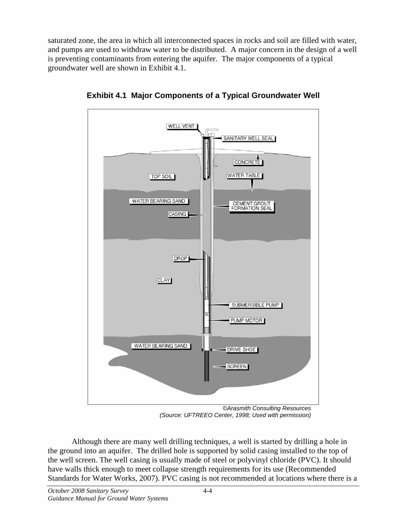
October 2008 Sanitary Survey 4-4 Guidance Manual for Ground Water Systems
saturated zone, the area in which all interconnected spaces in rocks and soil are filled with water, and pumps are used to withdraw water to be distributed. A major concern in the design of a well is preventing contaminants from entering the aquifer. The major components of a typical groundwater well are shown in Exhibit 4.1.
Exhibit 4.1 Major Components of a Typical Groundwater Well
©Arasmith Consulting Resources (Source: UFTREEO Center, 1998; Used with permission)
Although there are many well drilling techniques, a well is started by drilling a hole in the ground into an aquifer. The drilled hole is supported by solid casing installed to the top of the well screen. The well casing is usually made of steel or polyvinyl chloride (PVC). It should have walls thick enough to meet collapse strength requirements for its use (Recommended Standards for Water Works, 2007). PVC casing is not recommended at locations where there is a

October 2008 Sanitary Survey 4-5 Guidance Manual for Ground Water Systems
chance that the overlying soil contains hydrocarbons that could permeate the casing and contaminate the deeper water being used.
A well screen is installed below the casing to allow water into the casing while
preventing the migration of sand and silt into the bottom of the well. The screen should be constructed of corrosion resistant material that is both strong and hydraulically efficient. The screen’s mesh size should be determined based on a sieve analysis of the formation or gravel pack materials. The screen should be installed so the pumping water level remains above the screen under all operating conditions (Recommended Standards for Water Works, 2007).
Wells are often equipped with submersible pumps and discharge lines that reach down
inside the casing into the water. Some wells have a lineshaft turbine pump mounted on top of their casings. Depending on the type of well pump being used, the casing will look different and will be equipped with different kinds of seals and vents. These differences and their potential deficiencies are described in more detail in section 4.2.1.1.
The well casing is usually surrounded by 1 to 2 inches of neat cement or cement grout. The grout fills the annular opening between the casing’s exterior and the edge of the hole drilled in the ground. Ideally, the annular opening should be large enough to allow a minimum of 1½ inches of grout around the casing.
Many States have standards or guidelines for existing and/or newly constructed wells.
The surveyor should follow the State’s standards when inspecting wells. 4.2.1.1 Surface Features
The well casing should extend at least 18 inches above the pump house floor and ground surface. If the location of the well is prone to flooding, the casing and its vent should extend high enough so they are not submerged during a flood. At locations prone to flooding, a PWS should ensure the top of the casing stands at least 3 feet above the 100 year flood level or the highest known flood elevation (whichever is higher) (USEPA, 2003a).
Wells with submersible pumps should be capped and the cap should be sealed so no
water or contamination can enter the well. Seals should fit properly to accommodate all well appurtenances. If the well is not housed, the well cap should be locked and lightning protection should be provided.
One type of well seal used with submersible turbine pumps is a sanitary well seal with an
expandable gasket to allow the pump drop pipe, wires and vent to pass through it. This type of seal, shown in Exhibit 4.2, is typically used in wells housed in a well house. Bolts tighten two plates together, expanding the gasket material located between the plates. It seals the openings around the casing, pump drop pipe, the inverted U-type screen vent, and the electrical conduit.
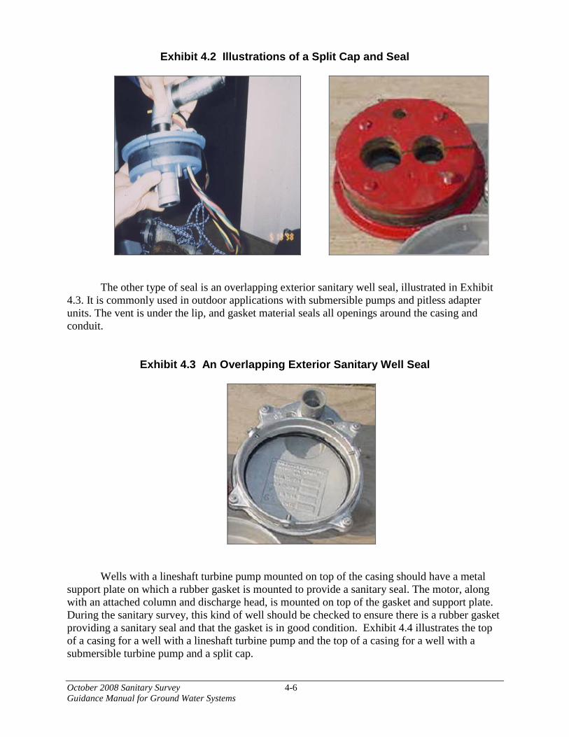
October 2008 Sanitary Survey 4-6 Guidance Manual for Ground Water Systems
Exhibit 4.2 Illustrations of a Split Cap and Seal
The other type of seal is an overlapping exterior sanitary well seal, illustrated in Exhibit
4.3. It is commonly used in outdoor applications with submersible pumps and pitless adapter units. The vent is under the lip, and gasket material seals all openings around the casing and conduit.
Exhibit 4.3 An Overlapping Exterior Sanitary Well Seal
Wells with a lineshaft turbine pump mounted on top of the casing should have a metal
support plate on which a rubber gasket is mounted to provide a sanitary seal. The motor, along with an attached column and discharge head, is mounted on top of the gasket and support plate. During the sanitary survey, this kind of well should be checked to ensure there is a rubber gasket providing a sanitary seal and that the gasket is in good condition. Exhibit 4.4 illustrates the top of a casing for a well with a lineshaft turbine pump and the top of a casing for a well with a submersible turbine pump and a split cap.

October 2008 Sanitary Survey 4-7 Guidance Manual for Ground Water Systems
Exhibit 4.4 Top of Casing Illustration for a Well with a Lineshaft Turbine Pump
(left) and a Well with a Submersible Turbine Pump and a Split Cap
Well casings should be vented to the atmosphere. For wells with submersible pumps, the
vent should terminate in a downward “U” position, and should be located at or above the top of the casing. The vent’s opening should be screened with a 24 mesh corrosion resistant screen. Wells with turbine pumps mounted on top of the casing frequently are vented to the side of the casing. These vents should be located high enough to prevent water from entering them and should also be properly screened (Recommended Standards for Water Works, 2007).
The discharge from the well should have a sample tap with a smooth nozzle to allow for sampling before the addition of any chemicals or disinfectants and before any treatment step. A sample of the raw water will allow the water system to test for contaminants that might be present or any changes in source water quality.
Exhibit 4.5 illustrates surface construction features that provide for the protection and
proper operation of a well with a lineshaft turbine pump.
DISCHARGE LINE
PIPE PLUG WELL VENT
WIRE MESH
SANITARY SEAL POWER CABLE
TO SUBMERSIBLE
PUMP DROP PIPE FROM
SUBMERSIBLE PUMP
DISCHARGE HEAD
COLUMN SANITARY
SEAL
WELL CASING
HOLLOW SHAFT MOTOR
SUPPORT PLATE

October 2008 Sanitary Survey 4-8 Guidance Manual for Ground Water Systems
Exhibit 4.5 Surface Construction Features of a Well with a Lineshaft Turbine Pump
California Department of Water Resources (1998), with modifications.

October 2008 Sanitary Survey 4-9 Guidance Manual for Ground Water Systems
The following are suggested assessment criteria for the surface features of a well:
Is the well properly sealed at the surface? Does the casing extend at least 18 inches above the well slab, floor, or ground surface? Does the well vent terminate above the maximum flood level with a turned down gooseneck and corrosion resistant bug screen?
Surface runoff can migrate down the annular space along the outside of the well casing
and contaminate the aquifer. Therefore, all sources of leakage should be plugged to prevent contamination. The most visible point of leakage is the encasement at the surface. The construction of the well above the surface should prevent leakage down the outside of the well casing as well as through the casing cap that is located on top of the casing. By extending the casing at least 18 inches above the well slab, surface runoff should not be able to enter the casing. The well slab should be concrete and sloped away from the casing. The well casing cap should to be a watertight sanitary seal to prevent water from entering through it. In addition, the casing vent through the cap should extend above flood level to preclude surface runoff from entering the well directly and the end of the vent should be terminated with a downward turned gooseneck and screen to prevent rain and bugs from entering.
What is the general condition of the piping and valving, the site, and the electrical system? Do they appear to be well maintained? Does the electrical system have lightning protection? Can the pump be maintained easily and the water for the system continually supplied?
As the source for the water system, the well should be in good operational condition to
ensure that a dependable supply of high quality source water will be available at all times. Good operational condition means that the piping is not leaking or corroded, the valves and controls are operable, and the electrical system is protected from the elements and is not corroded. The well site should be graded to prevent ponding of surface water and to direct drainage away from the wellhead, and the housing and fencing should be properly maintained. Valves and meters should be fully functional and well maintained to keep out contamination. Personnel should have sufficient access to these valves for cleaning. The electrical system should be protected from lightning since the sudden electrical surge caused by lightning striking the wellhead or nearby may cause the electrical components to burn out. If the electrical components of the well are not functional, then the well will not operate. The surveyor should check for lightning protection and backup power supplies (see section 4.7 for more information on emergency power). Ground fault protection is important to protect the operator. 4.2.1.2 Subsurface Features
Because the casing is often the only well feature above ground, it is frequently impossible to visually survey much of a ground water supply well and verify that the proper design and construction methods were followed. The original well construction records (e.g., driller’s log, material settling data, well completion report or other State forms) and records of after-construction modifications to the well, if available, should be reviewed to verify that the well was properly constructed. The results of surveys and repair work performed by qualified technicians may provide additional information about the construction of the well. The surveyor should verify that design and construction methods meet applicable State requirements for wells.

October 2008 Sanitary Survey 4-10 Guidance Manual for Ground Water Systems
The following are suggested assessment criteria for the subsurface features of a well:
What is the depth of the well? The greater the depth of the aquifer used, the less chance there is that surface
contamination will degrade water quality. Deeper aquifers generally have a more consistent quality of water (USEPA, 2003a).
How deep is the well casing? Well casing is an important part of proper well construction. The casing of a well acts as
a barrier to surface water and contamination from other aquifers. It also prevents the bore hole from collapsing. The well casing houses the submersible pump and its discharge pipe, and provides a column of water that allows for positive pump suction head. The casing should be constructed of either steel or plastic, depending on the depth of the well and local regulations, and should adhere to the State’s well standards. The casing should extend up a minimum of 18 inches above the natural ground level or finished floor elevation or two to three feet above the maximum flood elevation. The casing should pass through all undesirable water bearing strata and extend down at least to the depth of the shallowest water bearing strata to be developed.
Is the annular space around the well casing filled with grout or bentonite clay?
The annular space around the casing should be filled with a material, such as bentonite or
grout, that will prevent the leakage of water from the surface and intervening water-bearing layers down the outside of the casing into the aquifer. During the sanitary survey, the surveyor should review the driller’s log, well completion report, and any other State-required forms or reports if available, to ensure that the well is grouted to a depth that prevents any contaminated water from overlying aquifers or the surface from entering the water that is being pumped and used. The PWS should be sure that wells are grouted a minimum 20 foot depth below the surface or meets State standards or criteria (USEPA, 2003a).
What is the screen constructed of? What is the depth of the screen?
Aquifers typically are unconsolidated materials, such as sand and gravel, or bedrock, depending on local geology. A screen allows the optimum amount of water to flow into the well while preventing abrasive sand and gravel from reaching the pump. The screen should be constructed of a material that is strong and will not degrade over time due to exposure to water and surrounding environmental conditions. The material generally chosen for the screen is stainless steel. Some wells do not have screens because they are unnecessary for certain aquifer materials (e.g., rock instead of sand/gravel).
Is drawdown measured? Is the pump set below maximum drawdown?
Drawdown is the difference between static water level and pumping water level.
Measuring drawdown is important because changes in the static water level or drawdown can indicate declining water tables, pump or other well problems. Such changes can also indicate well encrustation. A common parameter used to monitor well performance is specific capacity,

October 2008 Sanitary Survey 4-11 Guidance Manual for Ground Water Systems
which is calculated by dividing measured drawdown by the pumping rate. Drawdown should be regularly measured and recorded, and the surveyor should check that the location of the pump intake is below maximum drawdown to prevent the pump from running dry.
4.2.1.3 Well Construction and Completion Information
The PWS should have information (i.e., driller’s report, well completion report, pump and drawdown tests, State-required forms and reports) that shows the following:
• A casing that penetrates a confining stratum of clay, shale, or otherwise impervious
material;
• The annulus between the drilled hole and the casing is sealed using bentonite clay, neat-cement grout or other acceptable material; and this seal extends from the surface down and into the confining strata mentioned above (Recommended Standards for Water Works, 2007);
• The well is grouted for a minimum depth of 20 feet (USEPA, 2003a) or meets State standards/criteria;
• The well is drilled so it is sufficiently deep to not be directly influenced by surface water infiltration and meets any State standards/criteria related to this issue;
• The well is located at a distance sufficiently removed from a surface water body so it is not directly influenced by the surface water and meets any State standards/criteria related to this issue; and
• The well has been adequately evaluated with aquifer performance testing in accordance with a reviewed and approved yield/drawdown test and results clearly determine the transmissivity and capacity of the aquifer (Recommended Standards for Water Works, 2007).
4.2.1.4 Typical Defects
A well provides a direct conduit from the ground surface to the aquifer. If the well is not constructed properly, surface runoff and shallower aquifers can contaminate the aquifer tapped into by the well.
The following paragraphs describe typical well defects. Casing Too Low
Well casing should extend at least 18 inches above the floor of the well house or three feet above the maximum flood level and their vents should be facing downward and screened (USEPA, 2003a). Wells in areas prone to flooding can flood and allow surface water to wash contaminants into the well. Surface grading, which directs surface runoff toward the well, can

October 2008 Sanitary Survey 4-12 Guidance Manual for Ground Water Systems
also cause contamination. If the casing is not elevated above the floor and turned downward, surface water and atmospheric debris can fall into the well and contaminate it. If the well is housed, the well house should be properly drained so that water does not pool around or near the well. Improper Well Cap Gaps or holes in the well cap can allow contaminants to enter the well. The well cap should be welded on or have a threaded cap and should be free of any holes caused by corrosion (Recommended Standards for Water Works, 2007). PWS should be sure that wells be housed and the well housing be locked and secure. Well caps of wells that are not housed should be locked. No Sanitary Seal If a well is not sealed properly, contaminants can enter into the well. The top of the casing or pipe sleeve should have a well cover with a sanitary seal on it. A more detailed description of sanitary seals is provided in section 4.2.1.1. Well Not Grouted Properly
The annular casing should be grouted in any area where contaminants might enter the well, including a minimum 20 foot depth below the surface and through any aquifers that may contain contaminated water (USEPA, 2003a). Well not properly ventilated Proper engineering practices require that a well be vented to the atmosphere (Recommended Standards for Water Works, 2007) to allow equalization of pressure with the atmosphere and to prevent accumulation of hazardous gases such as hydrogen sulfide or methane. If such gases are present, the vent should terminate outside of any well house or confined space. The well vent should be faced downward and covered with a corrosion resistant mesh to prevent entry of contaminants or vermin. Well in pit Wells should not be placed in pits because pits are prone to flooding that can allow contaminants to enter the well. Pits are also usually confined spaces; water system operators entering a pit to tend to their well should be provided with appropriate confined space training. Preferably, pits should be filled in, a pitless adapter (if allowed or approved by the State) should be installed, and the well casing should be extended so it rises at least 18 inches above the ground once the pit has been filled. 4.2.2 Potential Sources of Contamination
During the field survey, the surveyor should verify that the inventory of potential sources of contamination has not changed and that the susceptibility determinations for the source do not need revision. New potential sources of contamination and changes in a well’s susceptibility may
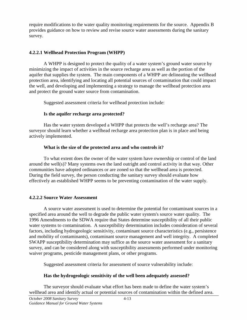
October 2008 Sanitary Survey 4-13 Guidance Manual for Ground Water Systems
require modifications to the water quality monitoring requirements for the source. Appendix B provides guidance on how to review and revise source water assessments during the sanitary survey. 4.2.2.1 Wellhead Protection Program (WHPP)
A WHPP is designed to protect the quality of a water system’s ground water source by minimizing the impact of activities in the source recharge area as well as the portion of the aquifer that supplies the system. The main components of a WHPP are delineating the wellhead protection area, identifying and locating all potential sources of contamination that could impact the well, and developing and implementing a strategy to manage the wellhead protection area and protect the ground water source from contamination.
Suggested assessment criteria for wellhead protection include:
Is the aquifer recharge area protected? Has the water system developed a WHPP that protects the well’s recharge area? The
surveyor should learn whether a wellhead recharge area protection plan is in place and being actively implemented.
What is the size of the protected area and who controls it? To what extent does the owner of the water system have ownership or control of the land
around the well(s)? Many systems own the land outright and control activity in that way. Other communities have adopted ordinances or are zoned so that the wellhead area is protected. During the field survey, the person conducting the sanitary survey should evaluate how effectively an established WHPP seems to be preventing contamination of the water supply. 4.2.2.2 Source Water Assessment
A source water assessment is used to determine the potential for contaminant sources in a specified area around the well to degrade the public water system's source water quality. The 1996 Amendments to the SDWA require that States determine susceptibility of all their public water systems to contamination. A susceptibility determination includes consideration of several factors, including hydrogeologic sensitivity, contaminant source characteristics (e.g., persistence and mobility of contaminants), contaminant source management and well integrity. A completed SWAPP susceptibility determination may suffice as the source water assessment for a sanitary survey, and can be considered along with susceptibility assessments performed under monitoring waiver programs, pesticide management plans, or other programs.
Suggested assessment criteria for assessment of source vulnerability include:
Has the hydrogeologic sensitivity of the well been adequately assessed? The surveyor should evaluate what effort has been made to define the water system’s
wellhead area and identify actual or potential sources of contamination within the defined area.

October 2008 Sanitary Survey 4-14 Guidance Manual for Ground Water Systems
If the well is located in a hydrogeologically sensitive setting, the surveyor should evaluate whether additional source water monitoring may be appropriate. If potential sources of contamination are identified near the well, the surveyor should determine if and how they are being managed to minimize their potential for contaminating the well, and whether the system’s source water protection program is protective enough.
Does the system monitor raw water quality? Does monitoring of raw water quality indicate an immediate, significant sanitary deficiency? If a well’s untreated water has tested positive for an indicator of fecal contamination or
for a harmful chemical, the system should be taking action to correct the deficiency or replace the source. Under the GWR, States may require corrective action for detection of fecal indicators. (See Exhibit 1.1). Detection of chemical contamination could be considered a significant deficiency and, under the GWR, the State may require corrective action.
4.2.2.3 Abandoned Wells Wells that are not properly abandoned can create pathways that allow contamination to enter an otherwise protected aquifer. Surveyors should ensure that any abandoned test wells and ground water sources have been properly disconnected and filled.
Suggested assessment criteria for well abandonment include:
Is the system confident that all abandoned wells have been identified? Have they been properly abandoned? An abandoned well should be sealed in a manner that restores geological conditions that
existed before the well was installed (Recommended Standards for Water Works, 2007). The well should be filled, preferably with cement grout or concrete, and sealed to prevent any water from passing into the aquifer (or in accordance with State or local requirements). 4.2.3 Source Quantity and Capacity
One of the most important requirements for any water system is the ability to meet the water quantity demands of customers at all times. Similarly, when demands exceed the treatment capacity of the supply, transmission lines, pumps, distribution system piping, or storage facilities, inadequate flow or pressure in the system can result. Inadequate flow or pressure affects customers, hinders fire fighting capabilities, and creates opportunities for other liquids to enter the system through cross-connections and a reduction in positive pressure.
States may have guidelines for estimating the average daily water use per person for various types of business and residential uses. The values may vary nationally and seasonally due to frequent lawn watering, swimming pools, industrial and commercial process water, cooling water and fire fighting. However, if no specific water consumption figures are available, water consumption estimates can often be found in water supply engineering books. These books have national averages for per capita demand and also supply typical factors for peak daily or hourly demands.
October 2008 Sanitary Survey 4-15 Guidance Manual for Ground Water Systems
States may have reporting requirements regarding source withdrawals and may impose
limits on the volume of water that can be withdrawn from sources, including ground water sources (i.e., adjudicated basins). If other State agencies have the responsibility for these types of regulations, the sanitary survey can verify that the system continues to have adequate source capacity to meet current demand and that recordkeeping is adequate.
In many places, particularly in arid and heavily populated areas, water conservation is necessary. Water systems should have a water conservation plan that includes short- and long-term goals, education plans, water rationing procedures in case of drought, and water conservation information available to the public. An aggressive water conservation plan can be a cost-effective alternative to the expansion of water production facilities.
One of the initial steps of the onsite visit should be determining if the system capacity meets current demands. The capacity should be at least equal to the maximum daily demand of the water system over the previous several years or as determined by the rules and regulations of the State primacy agency. PWS should be sure that the developed ground water capacity should equal or exceed the design maximum daily demand when the highest producing well is out of service. Reviewing the operating records of the plant should provide the maximum daily demand. Generally, the maximum daily demand occurs during the summer time. However, there have been situations where the maximum daily demand occurred during hard freezes in the winter when customers left faucets running to prevent their water pipes from freezing. Operating records for the last few years should be checked to determine the historic maximum daily demand.
Suggested assessment criteria for evaluating the adequacy of the source water supply are:
If permits are required, is the facility operating within the limits? Are permits available? Some States require systems to have permits that limit withdrawals or pumping rates.
During the sanitary survey, the surveyor should verify that the amount of water being pumped does not exceed the amount of water the system is permitted to withdraw.
Does the system have an operational master meter(s)? Without an operational and calibrated master meter, it is difficult for the water system to
accurately monitor production. With a master meter in place, the system can monitor overall production and water usage in the system to determine if supply is adequately meeting customer demand. Data from a master meter, combined with information from service connection meters, can be used to identify and track trends in water supply, water usage, and unaccounted for water that may be lost due to distribution system leaks.
How many service connections are there? The total number of homes and businesses served by the PWS provides the surveyor with
an idea of the size of the system.

October 2008 Sanitary Survey 4-16 Guidance Manual for Ground Water Systems
Are service connections metered? The system should have meters in place to monitor overall production and water usage in
the system to determine if supply is adequately meeting customer demand. Data from meters can be used to identify and track trends in both water supply and usage so that any potential future shortages can be noticed earlier and additional supplies obtained.
Does the system have interconnections with neighboring systems or a contingency plan for water outages? The system should plan for water outages so that water can be restored quickly.
Interconnections should only be made with approved sources. Does the system have redundant sources? Emergency supplies should be made available during outages. Many States require
community water systems with ground water supplies to have at least two sources in case one is lost.
What is the water quantity required to meet the needs of the water system? The water system should be able to supply an adequate quantity of potable water to meet
the highest anticipated demand of the customers. If not, then areas of the distribution system may experience little or no pressure due to the lack of water. With the loss of pressure, the contamination potential of the system is heightened significantly. Knowing the maximum water demand of the system and the quantity available from the source, a quick determination can be made of the system’s ability to meet the present and future needs of its customers. In addition, the water system should plan for the growth of its service area and look ahead to obtaining an adequate quantity of water to meet any additional future needs. If operating records show decreasing water quantity over time, the system should be investigating additional supply.
Is the source adequate to meet the current and future expected needs of the water system, even during times of drought? If not, what other sources are being investigated to meet the needs? Has the water system developed and implemented a water conservation plan? The surveyor can verify that an adequate supply is available by checking to see if the
source has ever gone dry or if water has ever had to be rationed because of a shortage of source water. A water system may have developed a water conservation plan as part of its overall water system master plan and may already be implementing the water conservation plan regardless of the adequacy of source water quantity. Implementation of a good water conservation plan can be a cost-effective alternative to the expansion of water production facilities as a result of increased demand. If the source water supply appears to be inadequate, the water system should be in the process of implementing further water conservation measures and/or obtaining an additional supply.
October 2008 Sanitary Survey 4-17 Guidance Manual for Ground Water Systems
4.2.4 Confirm Well Locations
It is important that the well(s) for a PWS be located as accurately as possible. The well(s) may have been located previously and the surveyor need only verify that the location(s) is correct. The surveyor may find that a new well has been constructed since the last survey, either authorized or unauthorized, and a previous one has been abandoned and/or plugged. The surveyor should make note of this new condition and advise the system if they should report the new well to the State. A United States Geological Survey (USGS) 7.5-minute topographic quadrangle or similar map can be used to plot the location of the water sources. A GPS can be used to determine the precise location of a well.
The following assessment criteria are suggested for the location of source water facilities:
What is the flood level in the area of the source facility? Can the source facility be flooded? The source water supply facilities should be able to operate at all times to produce safe,
potable water to meet the customers’ needs, regardless of the surrounding conditions, either man-made or natural. The source facility should be able to supply water to maintain an adequate pressure in the distribution system that, for safety purposes, would provide water for fire fighting, pressure to keep contaminants out, and meet the basic consumer necessities. If the source facility is flooded, the ability to supply water to satisfy these demands may be compromised.
Has the source facility ever been flooded? If so, was the operation of the source facility impaired? If the source facility has been flooded and operation not impaired, what is the access to the source facility during a flood? Depending on the design of the facility, portions of the plant could have been flooded, yet
it was still able to produce potable water. In this situation, access to the source facility needs to be maintained to allow for the ingress/egress of personnel and equipment as needed.
4.2.5 Source Water Transmission For some ground water systems, ground water may travel from the well to its point of treatment through a transmission line. The transmission line presents a potential opportunity for liquids and materials to both enter and leave the system. If the transmission line is not in good condition, contaminants may enter the water in the line or may cause the supply to be interrupted. Transmission lines need to be assessed for sanitary risks during the sanitary survey. The surveyor should travel along the raw water transmission line and speak with the operators to verify information already obtained from maps and other records about the location of transmission lines, air release valves, pressure release valves, drain valves, and other pertinent information.
Suggested assessment criteria for the raw water transmission lines include: Do the transmission lines deliver all the raw water directly to the treatment plant?

October 2008 Sanitary Survey 4-18 Guidance Manual for Ground Water Systems
The surveyor should check for any connections that may deliver untreated water to
customers (if treatment is required). If there are any connections to customers directly from the transmission lines, the surveyor should check if adequate treatment is being provided. If not, the surveyor should inform the system that the connections present a sanitary risk and should be removed. Are transmission lines in place that can bypass a treatment plant?
If treatment is required, the transmission pipes should not contain any valves that could
be opened and permit bypassing. Closed valves are generally not considered sufficient to prevent raw water from bypassing treatment. If a bypass is in place, the surveyor should confirm how it is controlled, and evaluate what preventative measures are in place to prevent the delivery of untreated water to consumers.
What are the age and condition of the transmission lines?
If the system relies on a single transmission line, a failure of this line could leave the
system and consumers without water. The surveyor should evaluate the potential for failure of the transmission pipes. If they seem to be in poor condition due to age or deterioration, or vulnerable to natural events (e.g., weather conditions, earthquakes), the surveyor should assess the potential for failure and subsequent interruptions to the water supply.
Are the transmission facilities redundant?
The surveyor should evaluate whether the disruption of a single transmission line would
leave the system without water, and the potential for such a disruption. Under such circumstances, the surveyor should recommend additional transmission lines or an emergency connection to another water supply. 4.2.6 Site Security
There are numerous ways the water supply for a system can be contaminated or
interrupted. A well’s components can be tampered with or destroyed. A well pump can be damaged or stolen. Contaminants can be intentionally or unintentionally introduced down the well casing. Wellheads located near a parking lot or street can be damaged by traffic accidents. During a sanitary survey, the surveyor should review what security is in place to protect each of the components of the water system. Where appropriate, the surveyor should confirm that an emergency response plan has been developed and is regularly exercised.
Suggested assessment criteria for evaluating security of the ground water source and its
facility include: Is the wellhead protected from vandalism and accidents? The location of the wellhead will dictate the measures required to protect it from
vandalism or physical damage. For instance, a security fence and structurally sound buildings

October 2008 Sanitary Survey 4-19 Guidance Manual for Ground Water Systems
with locked doors and entry alarms would protect the wellhead from intentional vandalism. Bollards around the well may be appropriate to protect it from traffic accidents.
Is the area around the wellhead restricted in accordance with primacy agency rules? Typically, the wellhead is unmanned and may be visited once a shift or once per day.
Therefore, there may be no continuous means to observe all the activities around the wellhead. Restricting access to the area with fencing and signs will limit the possibility of sabotage or accidental contamination.
Are transmission lines vulnerable to natural disasters or man-made damage? Surveyors should evaluate whether transmission lines are exposed to potential destruction
due to man-made damage or natural disasters. In those situations where tampering or destruction seem more possible, the surveyor should find out if the system has a plan for responding to such an interruption of water.
4.2.7 General Housekeeping
The physical condition of the source facility can be a good indicator to the surveyor of how often the facility is visited and how well it is maintained. All critical facilities should be visited by the operator frequently to determine that all equipment is operating correctly. If the equipment appears to be in good condition, then the system places value on preventive maintenance. However, if the equipment does not appear to be in good condition, then the system may not consider preventive maintenance a high priority. The system may have little money available or allocated for maintenance or inadequate staffing levels to perform maintenance.
Suggested assessment criteria for evaluating the housekeeping of the source and its facility include:
How often is the facility visited? Source facilities should be checked by system personnel frequently based on an
established schedule. The schedule should take into consideration the location and vulnerability of the source, treatment provided at the source and historical problems with equipment or vandalism.
Does the facility appear to be well maintained – grass mowed, equipment painted, facilities kept clean, etc.? The appearance of the facility does not directly impact the quality of the water, but it
does provide an indication of the overall amount of maintenance that the facility probably receives.
4.2.8 Cross Connections

October 2008 Sanitary Survey 4-20 Guidance Manual for Ground Water Systems
If the well has a blow-off or pump to waste piping, the outlet should not be directly connected to storm or sanitary sewers. The outlets of blow-offs and pump to waste piping should be protected from flooding and backsiphonage. 4.3 Treatment The types of treatment processes and facilities used to achieve safe drinking water are dictated primarily by the quality of the source water and the regulatory requirements that must be met. Typical ground water treatment processes often contrast sharply with treatment for surface water sources because all surface water sources are assumed to be contaminated by harmful microorganisms like Giardia. Therefore, surface water systems and systems with sources that are ground water under the direct influence (GWUDI) of surface water usually require treatment methods that will physically remove pathogens. Examples of these treatment methods include coagulation/flocculation, sedimentation/clarification, and filtration processes. Additionally, disinfection is required to inactivate any pathogens that are not physically removed.
Ground water systems are different than systems using surface water or GWUDI of
surface water, in that ground water systems often have natural filtration through the aquifer material and contain little or no turbidity; therefore, the physical removal steps noted above may not be necessary. On the other hand, ground water systems may require treatment to comply with other regulatory requirements (e.g., lead and copper, nitrate/nitrite, SOCs/VOCs (i.e., synthetic organic contaminants/volatile organic contaminants), radiological contamination, etc.) or other aesthetic water quality contaminants (e.g., iron, manganese, color, and/or taste and odor).
The person conducting the sanitary survey should evaluate all water treatment processes in use at the water system. This evaluation should consider the design, operation, maintenance, and management of the water treatment plant to identify existing or potential sanitary risks. Water treatment facilities are the primary means of preventing unacceptable drinking water quality from being delivered for public consumption. The treatment facilities and processes should be capable of removing, sequestering, or inactivating physical, chemical, and biological impurities in the source water and meeting MCL or treatment technique requirements.
For ground water systems, the regulatory requirements of the GWR and Stage 2 D/DBP Rule place additional demands on the treatment facilities. While some ground water systems will be installing disinfection as a corrective action to comply with the GWR, those and other systems should be careful not to exceed Stage 2 D/DBP Rule’s locational TTHM and HAA5 MCLs as a result. Alternatively, ground water systems with disinfection already in place that are having difficulty complying with the Stage 2 D/DBP Rule should not make adjustments to their disinfection that result in an increased microbiological risk to customers. The treatment facilities and processes should be evaluated to determine their ability to meet these regulatory requirements and to provide an adequate supply of safe drinking water at all times, including periods of high water demand. A sanitary survey of a treatment facility should

October 2008 Sanitary Survey 4-21 Guidance Manual for Ground Water Systems
• Analyze all the distinct parts of the treatment process, including but not limited to disinfection, chemical feed systems, hydraulics, controls, and wastewater management.
• Identify features of the water treatment process that may pose a sanitary risk, such as inadequate treatment, monitoring, or maintenance, lack of reliability, and cross connections.
The surveyor will need to review and consider specific regulations that apply to the
facility, design criteria, plant records, and past survey reports that may identify previous compliance problems, in addition to performing the actual survey of the facility. The following sections discuss specific portions of common treatment facilities that may be evaluated during a sanitary survey.
4.3.1 Treatment Plant Schematic/Site Plan
A schematic or site plan indicating the location of the treatment plant, type(s) of treatment provided, and chemical injection points will enable the surveyor to obtain a quick understanding of the treatment type(s). If possible, the surveyor should review any schematics or site plans prior to the sanitary survey. The schematic/site plan should be drawn in enough detail to facilitate the surveyor’s understanding of the treatment facilities.
Each treatment facility should be assigned a name and identification number.
Additionally, the schematic/site plan drawings should be dated to assist future surveyors in identifying changes in the water system. The schematic/site plan drawings should be updated during each subsequent sanitary survey to reflect any changes in the system.

October 2008 Sanitary Survey 4-22 Guidance Manual for Ground Water Systems
Exhibit 4.6 Example Schematic Diagram of a Ground Water Treatment Plant
4.3.2 Capacity of Treatment Facilities One of the initial steps for the surveyor will be to determine if the existing treatment facilities meet current system demands. The State primacy agency may have design standards that specify the capacity requirements for source water supplies and individual treatment units. Manufacturers of treatment equipment also have specifications for the operation of pumps, contact tanks and other components. Treatment plants are designed and built to accommodate a specified flow. The existing treatment facilities should be evaluated to determine if the specified capacity requirements are being met. If the system has been approved or permitted by the State to be operated under specific conditions (e.g., maximum flow), the surveyor should check that the system is adhering to the approved operating conditions. The following are suggested assessment criteria to determine the adequacy of the treatment facility capacity:
What is the design capacity of the treatment units? What is the maximum daily demand of the system? Given the number of service connections and/or the population served by the system, is the capacity of the treatment facilities reasonable? Design or permitted capacity can be found in plant records and State records and permits.
Design and construction documents can also be used to determine capacity. If these records and documents are unavailable, the surveyor will need to discuss with the system’s operator the purpose of the treatment; the maximum capacity of the treatment units in relation to the system’s peak demands; and whether adequate treatment is being provided. Based on this information, the
October 2008 Sanitary Survey 4-23 Guidance Manual for Ground Water Systems
surveyor can draw conclusions on whether the treatment facilities can provide adequate treatment during peak demand periods, or whether expansion plans or upgrades should be considered.
If the primacy agency has specific treatment unit capacity requirements, does the system meet these requirements? Many primacy agencies have design standards and/or minimum requirements for the
capacities of major treatment units. The surveyor will need to compare the system’s existing treatment capacity with those required by the primacy agency.
Are the treatment facilities capable of meeting the required capacity with the largest unit out of service? Treatment facilities will require maintenance, repair, and replacement from time-to-time;
therefore, redundancy should be provided that will allow the system to provide adequately treated water during these periods. To ensure adequate capacity is available at all times, the capacity of a major treatment process should be determined with the largest treatment unit out of service.
4.3.3 Chemicals and Chemical Feed Systems Chemical feed systems are common to many ground water treatment plants. These
systems can be used to feed treatment chemicals such as disinfectants, oxidizers, corrosion inhibitors, pH adjustment chemicals, chemicals for sequestration, fluoridation, etc. The types of chemicals that are used depend on the specific treatment facilities and the objectives of the treatment processes. Types of chemical feed systems include liquid feed pumps and dry chemical feed. 4.3.3.1 Liquid Chemical Feed Systems
A typical liquid chemical feed system would include: • Storage tank to hold the chemical solution;
• A metering chemical feed pump with a suction line extended into the storage tank;
• A discharge line with check valve and an injection valve at the point of application;
and
• A flow-switch to control the metering pump operation. If the flow switch is automatic, it must be tied to a flow meter or another control sensor.
A typical liquid chemical feed system is shown in Exhibit 4.7.
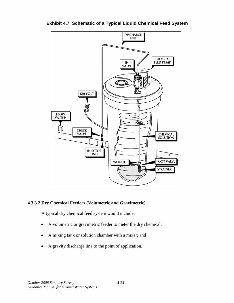
October 2008 Sanitary Survey 4-24 Guidance Manual for Ground Water Systems
Exhibit 4.7 Schematic of a Typical Liquid Chemical Feed System
4.3.3.2 Dry Chemical Feeders (Volumetric and Gravimetric)
A typical dry chemical feed system would include: • A volumetric or gravimetric feeder to meter the dry chemical;
• A mixing tank or solution chamber with a mixer; and
• A gravity discharge line to the point of application.

October 2008 Sanitary Survey 4-25 Guidance Manual for Ground Water Systems
The following are suggested assessment criteria for chemical feed systems:
What chemicals are in use? Are the chemicals in use approved for use in drinking water? The surveyor should inspect chemical containers and discuss with the operator what type
of chemicals are used and their purpose. The surveyor should check that the chemicals in use carry the NSF or Underwriters Laboratories (UL) markings to ensure the chemicals used conform to all applicable requirements of NSF Standard 60: Drinking Water Chemicals—Health Effects. Treatment plant operators may be using compounds or chemicals that are not approved for drinking water (e.g., household bleach in place of NSF approved sodium hypochlorite).
Are the chemicals in use appropriate for the water system? The surveyor should discuss with the operator and assess whether the chemicals used in
treating the water are appropriate. Water systems may purchase and use chemicals that are not appropriate for their existing plant or treatment objectives.
What are the chemical dosages—minimum, average, and maximum? Are the chemical feed facilities appropriately sized for the dosages in use? The surveyor should ascertain whether the treatment plant has the capacity to apply the
appropriate amount of chemicals at peak demand periods. Often, having chemical feed systems sized to deliver one hundred and fifty percent of maximum is recommended as a rule-of-thumb.
Where is each chemical applied? The surveyor should examine chemical feed points and note where and how the
chemicals are added, whether the feed points are active or for standby, whether the points of application are appropriate, and whether the feed points allow for chemical compatibility. Some chemicals may counteract each other if not properly applied. For example, if the system was introducing an oxidant (chlorine) prior to the application of chemicals used for sequestration of iron and manganese, the chlorine would oxidize the iron and manganese before the sequestering chemicals could work to keep the iron and manganese soluble in the finished water. As noted earlier, these points of chemical application should be noted on the system site plan or schematic.
As a general rule, the surveyor should know the application points and feed rates of all
chemicals used in the system’s treatment plants. The purpose of the chemicals must be understood so that the appropriateness of the feed locations and rates can be evaluated. This may require the surveyor to perform research on the chemicals the system uses either before or after the sanitary survey.
What type of chemical feed equipment is used? What is the condition of the chemical feed equipment? Is chemical feeder redundancy provided? The surveyor should note the type of chemical feed equipment in use and its ability to
feed chemicals on a continuous basis. The equipment must be functional and properly maintained. For example, with dry chemical feeders, the surveyor should watch for problems with “bridging” of the chemical in the hopper. Liquid feeder lines should be checked to see that

October 2008 Sanitary Survey 4-26 Guidance Manual for Ground Water Systems
they are not clogged. Redundant equipment should be provided and should be of sufficient capacity to replace the largest chemical feed unit. The surveyor should determine if there is a preventative maintenance program in place and should examine repair records and the system’s supply of the spare parts and/or redundant equipment.
Is the chemical feed equipment calibrated, and how does the operator determine the amount of chemicals used? Calibration should be completed each time a new batch of chemicals is used. The feed
equipment feed rate should be checked frequently. One method of checking is to use a graduated cylinder to verify the feed rate on a weekly or monthly basis (e.g. “pump catch”).
Is backflow prevention provided on the water lines used for chemical feed makeup? All lines supplying water for chemical feed makeup should be equipped with backflow
prevention devices or an air gap to prevent cross-connections and the potential contamination of potable water.
Is the chemical feed system flow paced? Pacing the chemical feed pump with flow can be accomplished by a 4-20 mA signal from
a flow recorder, or the system may be tied directly to a pump so that the feeder is activated each time the pump is operated and there is flow in the line. However, when the chemical feeder is tied to a pump, it is very important that some type of flow sensing device be used as a fail safe. The chemical feeder should not be allowed to come on until there is a flow in the pipe. Without flow control it is possible for a pump motor starter to engage and not start the pump. If the signal that engaged the starter also starts the chemical feed system, then highly concentrated chemicals can be fed into the line and received by a customer.
What type of chemical storage facilities is provided? Is the storage area for each chemical adequate and safe? Is secondary containment provided? Are incompatible chemicals stored together? The chemical storage area capacity should be adequate to allow space for free access for
loading and unloading of chemicals. A minimum 30-day supply for chemicals is recommended. The bulk storage facility should have indicators for chemicals storage levels. The storage containers should have a convenient method for determining the amount of chemical in each container. The storage facility should have safeguards against accidental spills, and like every other treatment space, should have a clean water source under high pressure and a drain for effective cleaning and decontamination. In the case of some gaseous chemicals, like chlorine, special ventilation equipment and the availability of Occupational Safety and Health Administration (OSHA) approved breathing apparatus may be required. Breathing equipment and other personnel safety equipment and gear should be stored outside the storage area where the equipment can be safely accessed. Incompatible chemicals should be stored separately (e.g., gasoline for maintenance equipment, strong acids should not be stored near chlorites). The chemicals storage and the storage facility itself should be located so as to not allow a chemical spill to reach the raw water source, the treated water, or water being treated. In addition, every container in the storage area should be labeled and every storage area should be labeled to identify what chemicals are supposed to be stored in it.
October 2008 Sanitary Survey 4-27 Guidance Manual for Ground Water Systems
What is the condition of the building/room where the chemicals and chemical feed equipment are stored? Is adequate ventilation provided? The surveyor should check to ensure that the interior of the building housing the
chemicals is kept clean and dry. The general condition of the building housing the chemicals is an indicator of the maintenance standards at the facility. Spills of chemicals can cause unsafe conditions and/or increase corrosion within the building. Adequate ventilation, heating, and air conditioning are important in maintaining the sanitary integrity of the building. Equipment used for controlling and removing dust and vapors should be functional and effective.
4.3.4 Disinfection The practice of water disinfection has proven to be one of the most important advances in
reducing the incidence of waterborne disease. In this regard, disinfection is an important corrective action alternative for the GWR. Disinfection is the process of destroying or inactivating a large portion of the microorganisms in water, with the probability that all pathogenic bacteria or viruses are destroyed or inactivated in the process.
Chlorination is the most common disinfection method used by water systems in the United States, because of its proven effectiveness, low capital and operating costs, and its established history in the water industry. Free chlorine provides a high level disinfection at the point of application and a measureable residual in the distribution system
4.3.4.1 Dosage and Residual
Dosage: The total amount of chlorine fed into a volume of water by the chlorinator is the dosage. This value is correctly calculated in milligrams per liter (mg/L); however, mg/L and parts per million (ppm) are generally interchangeable in water treatment calculations.
Demand: Chlorine is a very active chemical oxidizing agent and combines readily with
certain inorganic substances that are able to oxidize (e.g., hydrogen sulfide, ferrous iron, manganese, and nitrite), organic impurities, and organic nitrogen compounds. These reactions use or consume some of the chlorine, and the amount that is used is called the chlorine demand. The reaction time between chlorine and most organic compounds is long (hours to days); therefore, the demand is based on time (i.e., the measurable demand at the end of 20 minutes is less than the measurable demand at the end of one hour of contact, due to the amount of time the chlorine has to react with the organic compounds).
Residual: Residual is the amount of chlorine present in the water after a specified period of time and is measured in mg/L.
Chlorine demand (mg/L) = Chlorine Dose (mg/L) - Chlorine Residual (mg/L)

October 2008 Sanitary Survey 4-28 Guidance Manual for Ground Water Systems
4.3.4.2 Chlorine and Water
Regardless of the form of chlorination – chlorine gas or hypochlorite – the reaction in water is essentially the same. Chlorine mixed with water will produce two general compounds, HOCl (hypochlorous acid) and OCl- (hypochlorite ion). The measurement of these compounds is called free chlorine residual. If organic or inorganic compounds, especially nitrogen compounds, are available, the HOCl will combine with these compounds to produce chloramines and/or chloro-organic compounds. The measurement of the presence of these compounds in water is called the combined chlorine residual.
Breakpoint Chlorination: As stated previously, chlorine will react with inorganic and organic compounds in natural waters. The chlorine will react with (oxidize) iron, manganese, and nitrites. These chemicals are reducing agents (i.e., substances that are oxidized), and no residual can be formed until all of the reducing agents are oxidized. As more chlorine is added, the chlorine will begin to react with organic matter and ammonia to form chloro-organic compounds and chloramines, resulting in the combined chlorine residual mentioned previously. With the addition of more chlorine, the residual will decrease due to the oxidation of chloramines and chloro-organic compounds until chloramines reach a minimum value. Beyond this minimum point, the addition of more chlorine produces an increasing amount of free residual chlorine. This process is called breakpoint chlorination. While this process destroys most of the nitrogen compounds, it does not destroy all of them. Those that remain combine with the chlorine to produce what is called the irreducible combined residual.
Exhibit 4.8 Breakpoint Chlorination Curve
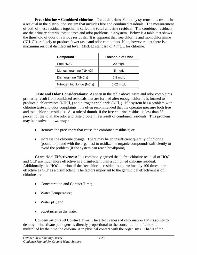
October 2008 Sanitary Survey 4-29 Guidance Manual for Ground Water Systems
Free chlorine + Combined chlorine = Total chlorine: For many systems, this results in a residual in the distribution system that includes free and combined residuals. The measurement of both of these residuals together is called the total chlorine residual. The combined residuals are the primary contributors to taste and odor problems in a system. Below is a table that shows the threshold of odor of various residuals. It is apparent that free chlorine and monochloramine (NH2Cl) are likely to produce fewer taste and odor complaints. Note, however, that there is a maximum residual disinfectant level (MRDL) standard of 4 mg/L for chlorine.
Compound
Threshold of Odor
Free HOCl
20 mg/L
Monochloramine (NH2Cl)
5 mg/L
Dichloramine (NHCl2)
0.8 mg/L
Nitrogen trichloride (NCl3)
0.02 mg/L
Taste and Odor Considerations: As seen in the table above, taste and odor complaints
primarily result from combined residuals that are formed after enough chlorine is formed to produce dichloramines (NHCl2) and nitrogen trichloride (NCl3). If a system has a problem with chlorine taste and odor complaints, it is often recommended that the operator measure both free and total chlorine residuals. As a rule of thumb, if the free chlorine residual is less than 85 percent of the total, the odor and taste problem is a result of combined residuals. This problem may be resolved in two ways:
• Remove the precursors that cause the combined residuals; or
• Increase the chlorine dosage. There may be an insufficient quantity of chlorine (pound to pound with the organics) to oxidize the organic compounds sufficiently to avoid the problem (if the system can reach breakpoint).
Germicidal Effectiveness: It is commonly agreed that a free chlorine residual of HOCl
and OCl- are much more effective as a disinfectant than a combined chlorine residual. Additionally, the HOCl portion of the free chlorine residual is approximately 100 times more effective as OCl- as a disinfectant. The factors important to the germicidal effectiveness of chlorine are:
• Concentration and Contact Time;
• Water Temperature;
• Water pH; and
• Substances in the water
Concentration and Contact Time: The effectiveness of chlorination and its ability to
destroy or inactivate pathogens is directly proportional to the concentration of chlorine multiplied by the time the chlorine is in physical contact with the organisms. That is if the

October 2008 Sanitary Survey 4-30 Guidance Manual for Ground Water Systems
concentration of chlorine is decreased, the contact time must be increased for chlorine to retain the same germicidal effectiveness. Similarly, if the contact time is decreased, the chlorine concentration must be increased for chlorine to be effective. The product of the chlorine concentration (C) multiplied by the contact time (T) is referred to as “CT”. CT is measured in milligram-minutes per liter (mg-min/L) and is calculated as follows:
Disinfectant residual concentration in mg/L (C) X contact time in minutes (T) = CT in mg-
min/L
In order to obtain primacy for the GWR, a State must explain the process it will use to determine that a ground water system achieves at least 4-log treatment of viruses. Many States will use CT as the foundation for making that determination with respect to disinfection. Appendix A provides a more detailed explanation of CT and how it should be calculated for GWSs.
Water Temperature: Other factors being equal, chlorine is more effective as a germicide at higher water temperatures. At lower temperatures, the destruction of pathogens tends to happen at a slower rate.
Water pH: The pH of water determines the ratio of HOCl to OCl-. HOCl is the
dominant residual at lower pH, while OCl- is the dominant residual at higher pH. This is noteworthy, because ground waters often have a relatively high pH, resulting in OCl- being the dominant residual. And as stated above, OCl- is much less effective as a germicide than HOCl.
Substances in Water: Chlorine is only effective if it comes in contact with the
organisms to be destroyed; therefore, substances in the water (e.g., sand, dirt, iron, manganese, and other constituents of ground waters) can “hide” or protect pathogens from contact with the chlorine and reduce the germicidal effectiveness of the chlorine. In ground water, this is an issue with systems that pump sand or have iron, manganese, or other constituents of ground waters, and removal of these substances may be required for effective chlorination.
The following are suggested assessment criteria for assessing chlorine dosages and
residuals: Does the operator understand the disinfection process? The operator should be knowledgeable about the disinfection process and the facilities
used at the treatment plant to provide adequate disinfection treatment. The lack of knowledge by the operator of the disinfection process and the equipment is an indicator that equipment failure or other problems may not be resolved in a timely manner.
Have there been any interruptions in disinfection? If so, why? The surveyor should assess if there were any interruptions in disinfection and ascertain
what steps have been taken to prevent further interruptions.
October 2008 Sanitary Survey 4-31 Guidance Manual for Ground Water Systems
What disinfectant residual is maintained? Records of disinfection residuals leaving the plant and in the distribution system (if
applicable) should be checked. In addition to verifying that there is a proper residual, determine if the equipment and testing methods are adequate.
Is the contact time between the point of disinfection and the first customer adequate? As stated previously, the contact time is the interval in minutes (T) that elapses between
the time when chlorine is added to the water and the time when that same slug of water passes by the sampling point. A certain minimum period of time, depending on disinfectant residual concentration (C), water temperature and other factors, is required for completion of the disinfecting process. The requirements for contact time (T) and disinfectant residual concentration (C) depend on the pH, temperature and flow rate of the water. These records are especially important if the system is required to meet the 4-log virus inactivation requirements of the GWR.
For systems determining CT, are the temperature and pH of the water at the point of chlorine application measured and recorded? The CT value required for proper inactivation of viruses depends on the pH and
temperature of the water. Therefore, some ground water systems may be required to take these two measurements regularly and perform CT calculations at peak hourly flow. The pH should be measured with a meter, not with litmus paper or a color comparitor, and the temperature should be measured with a calibrated thermometer.
The following sections discuss gas and liquid chlorination in more detail. Brief
explanations of the processes and equipment used for each of these disinfection methods are described, and potential deficiencies are characterized. Readers are encouraged to refer to Appendix A for more information on disinfection and removal technologies.
4.3.4.3 Gas Chlorination Equipment used to feed gas chlorine is designed to work either under pressure or under a
vacuum. A vacuum-operated solution feed chlorinator is by far the most common of the two types of gas chlorinators. The vacuum-operated chlorinator will only feed chlorine gas when the equipment receives a vacuum signal. The gas is mixed with water to form a highly concentrated solution that is fed into the water at the point of application. The pressure-operated gas feed chlorinator is the other type of chlorinator and this equipment operates under pressure supplied by the gas and feeds to the point of application. The vacuum operated solution feed chlorinator offers greater safety in operation of the equipment and in the handling of the chlorine gas; additionally, these units provide for greater versatility in the application and control of the chlorine dosage.
The easiest way to tell the difference between a remote vacuum system and a pressure system is to observe the line leading from the cylinder to the chlorinator. If this line is metal, the system uses gas under pressure between the cylinder and the chlorinator. If the line is plastic, the

October 2008 Sanitary Survey 4-32 Guidance Manual for Ground Water Systems
system is a remote vacuum system. Gas is under a vacuum between the cylinder and the chlorinator.
Gas chlorine is provided in 100 pound and 150 pound cylinders, one ton containers, and
tank cars (55 to 90 tons). These values are the net weight of liquid chlorine in the container. With gas chlorination, the surveyor will need to focus on the reliability and adequacy of the system to provide disinfection. It should be noted, however, that there are significant dangers involved with gas chlorination systems. Gas chlorine is classified as a poison gas and an inhalation hazard by OSHA, EPA, and Department of Transportation (DOT); therefore, review of safety procedures and safety equipment is important. Typical Gas Chlorination Facility: The key points of a gas chlorination facility, in general, include:
• Containment of the chlorine, should there be a release or leak;
• Air treatment system so that the exiting air does not exceed 50 percent of the PEL (15 ppm is 50 percent);
• Gas leak alarm system;
• Crash bars on doors;
• Negative pressure in the room when the air treatment system is operating;
• Overhead sprinkler system with a 20-minute capacity;
• Containment of the air treatment system and sprinkler water;
• Emergency power for the air treatment system;
• Booster pump to provide pressure to the injector; and
• Scales to weigh the cylinders (USEPA, 2003a).
The sanitary deficiencies related to Chemical Feed Systems and Disinfection earlier in this chapter should also be applied to this section. The following are additional suggested assessment criteria for gas chlorination facilities:
How are leaks detected? At what detection concentration are automatic detectors set and have they been tested recently? Is the sensor tube for the automatic detector near the floor level, and is it screened?
Automatic chlorine leak detectors should be tested at least monthly. This can be
accomplished by placing a small pan of bleach under the air intake and adding some vinegar.
October 2008 Sanitary Survey 4-33 Guidance Manual for Ground Water Systems
Are there any cross-connections in the chlorine feed make-up water or injection points? All service water to operate injectors/eductors should be protected by an appropriate
cross-connection control device. Is there an alarm tied to interruptions in the chlorine feed? If there is an alarm system, does it work? Low system vacuum and low cylinder pressure
are the two most common alarm systems, and the surveyor should ask what would initiate an alarm. Does the alarm shut down the flow of water or just alert the operator of a malfunction?
Does the system use automation, pace with flow, chlorine residual analyzer, or other system to adjust feed rates? Does it work? The surveyor should determine whether the system provides adequate residual during
high flows and whether the residuals are higher during low flows. Is there more than one cylinder, and are they manifolded with an automatic switch-over to prevent running out of chlorine? The surveyor should determine whether the switch-over devices work. If there is only
one cylinder, determine if the operator shuts off water flow when the cylinder is changed. If not, then there is an interruption of disinfection.
Are the cylinders on a working scale? A scale should be used in order to determine the amount of chlorine used each day. In
order to calculate dosage and signal the amount of chlorine remaining in the cylinders, scales should be maintained and calibrated and kept in working order. Scales may not be working due to excessive corrosion caused by chlorine, and the surveyor should determine if new scales are needed.
Are the tanks in use a quarter turn open with a wrench in place for quick turnoff? Full feed of 40 pounds per day can be obtained from a cylinder by opening the valve one
quarter of a turn. It is not necessary to open the valve more than what provides the needed flow. By only opening it one quarter of a turn and leaving the wrench in place, the operator can quickly shut the cylinder down if there is a release.
Are all cylinders properly marked and restrained to prevent falling? Cylinders should be marked and stored in a manner that clearly indicates which cylinders
are full and which are empty. All cylinders should be restrained two-thirds of the way from the bottom with a chain that prevents falling. In an earthquake zone, they should also be restrained at or near the bottom.

October 2008 Sanitary Survey 4-34 Guidance Manual for Ground Water Systems
What procedures are followed during cylinder changes and maintenance? Has the utility provided detailed training on handling and changing cylinders? Check to see if there is a written standard operating procedure (SOP) for maintaining and
changing cylinders. If not, then there are opportunities for disinfection interruptions as well as safety concerns.
What is the operating condition of the chlorinator? Gas chlorinators should be disassembled, cleaned, and rebuilt each year. An observation
of the rotameter can provide a clue as to the frequency of cleaning. If it is coated on the inside with a heavy green or blackish film, the machine is past due for cleaning.
In addition, general appearance can also be a key. Check preventative maintenance and
repair records, and determine that preventative maintenance is routinely performed. Some indicators of problems for gas chlorination would be valves, piping, and fittings that are damaged, badly corroded, or loose; no gas flow to the chlorinator; or frost on tank, valves or piping.
Is redundant equipment available, and are there adequate spare parts? To provide effective public health protection, disinfection should be continuous.
Therefore, standby equipment of sufficient capacity to replace the largest unit is recommended. Where standby equipment is not available, flow to the water system should be halted, and critical spare parts should be on hand for immediate replacement. At a minimum, the system should have spare diaphragms and a set of lead gaskets. (Lead gaskets should not be reused.)
4.3.4.4 Liquid Hypochlorination Many facilities have switched to the use of hypochlorination as a safer and easier method
of disinfecting water than gaseous chlorine. The primary disadvantage to liquid chlorination is the increased annual operating cost over gas systems; however, as a result of new safety and environmental regulations, the cost of using chlorine gas has continued to rise, making the hypochlorination systems more common. Systems using hypochlorite should list it in their hazardous materials inventory and have written procedures for handling, using and responding to spills. 4.3.4.5 Typical Liquid Chlorine System There are two forms of hypochlorite that are used in a liquid chlorine system: sodium hypochlorite (liquid) and calcium hypochlorite (solid). Sodium hypochlorite is more corrosive and degrades over time. The rate of loss of sodium hypochlorite depends on the strength of the chemical and the temperature. The chemical deteriorates faster at higher concentrations and warmer temperatures. If sodium hypochlorite is used, the surveyor should determine the amount on hand and its age. Sodium hypochlorite is also corrosive so equipment should be corrosion resistant and checked frequently for signs of corrosion.

October 2008 Sanitary Survey 4-35 Guidance Manual for Ground Water Systems
Calcium hypochlorite is more stable than sodium hypochlorite. It is not as soluble, however, especially in hard water. Calcium hypochlorite also frequently contains abrasive material that can lead to more wear on pumps and valves. The following are suggested assessment criteria for liquid chlorine systems:
Is the disinfectant chemical used appropriately certified?
Chemicals introduced into drinking water should be certified as meeting the standards of NSF 60 or an equivalent standard. This certification ensures that the chemical has been tested and found acceptable for use in public water supplies.
What is the strength of the chemical feed solution?
In order to achieve the proper dose of chlorine the strength of the solution must be known. The operators should be familiar with procedures for preparing and testing the solution and determining the dose.
Is chemical storage adequate and safe?
It is recommended that systems have a 30 day supply of chemicals on hand to prevent running out of chemicals and losing disinfection capability. Hypochlorite is a strong oxidizer and should be kept away from any combustibles, especially petroleum products. Liquid storage should have spill containment around it. Proper safety equipment such as showers, eyewashes, and respirators should be available.
Is equipment operated and maintained properly?
Failure of the feed equipment could result in loss of disinfection. Therefore all equipment should be well maintained with a regular preventative maintenance schedule. Feed lines should be checked regularly to make sure they are not clogged. Clear plastic lines should be replaced if they become opaque.
Is standby equipment available?
If a feed pump fails, the system can lose disinfection capabilities. Therefore, the system should have at least one backup feed pump. If a valve fails, the system can lose disinfection capabilities. Therefore, a system should have adequate spare parts on hand to be able to quickly replace any valves in the chlorine feed system.
What is the pump model? Stroke and speed settings?
The operator should be familiar with the type and model of the chemical feed pumps. Chemical feed pumps generally have adjustable speed and stroke length that help to determine the feed rate. Stroke rates should be kept within the manufacturer’s specified ranges.
October 2008 Sanitary Survey 4-36 Guidance Manual for Ground Water Systems
Where are they storing their feed solution?
The feed solution should be stored in a covered, chlorine resistant tank. It should be in a clean and dry area and have the appropriate spill containment surrounding it.
How do they make up the chlorine feed solution?
The operator should be familiar with the process for mixing the chlorine feed solution. Proper safety equipment should be used for preparing the solution including gloves and goggles.
Is the chlorine feed manually or automatically adjusted for flow?
Disinfectant dose will need to be varied depending on flow rate. This can be done either by manually adjusting the pump or it can be done by hooking the pump to a flow sensor that adjusts pump rates in proportion to the measured flow rate in the pipe (flow-paced). Chemical feed should not be turned on if there is no flow. The operator should be familiar with calculating the required chlorine dose based on flow and determining if the pumps are delivering sufficient dose.
Are proper cross connection controls in place for the make-up water?
If finished water is used to provide water for chlorine injection, make-up water, or preparation of chlorine feed solutions, there should be proper cross connection controls to prevent backflow into the finished water lines. This means providing a sufficient air gap if a hose or faucet is used, or installing the appropriate backflow prevention devices if the line is piped into the feed facility. Exhibit 4.9 illustrates an appropriate air gap between a water feed line to a chlorine solution tank and the chlorine solution in the tank.
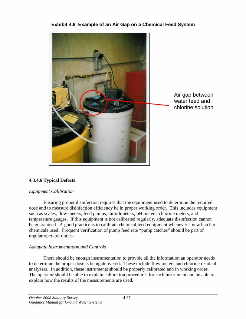
October 2008 Sanitary Survey 4-37 Guidance Manual for Ground Water Systems
Exhibit 4.9 Example of an Air Gap on a Chemical Feed System
4.3.4.6 Typical Defects Equipment Calibration
Ensuring proper disinfection requires that the equipment used to determine the required dose and to measure disinfection efficiency be in proper working order. This includes equipment such as scales, flow meters, feed pumps, turbidimeters, pH meters, chlorine meters, and temperature gauges. If this equipment is not calibrated regularly, adequate disinfection cannot be guaranteed. A good practice is to calibrate chemical feed equipment whenever a new batch of chemicals used. Frequent verification of pump feed rate “pump catches” should be part of regular operator duties.
Adequate Instrumentation and Controls
There should be enough instrumentation to provide all the information an operator needs to determine the proper dose is being delivered. These include flow meters and chlorine residual analyzers. In addition, these instruments should be properly calibrated and in working order. The operator should be able to explain calibration procedures for each instrument and be able to explain how the results of the measurements are used.
Air gap between water feed and chlorine solution

October 2008 Sanitary Survey 4-38 Guidance Manual for Ground Water Systems
Storage
Storage should be located in a clean dry location away from other incompatible chemicals such as petroleum products. Proper spill containment should be included around liquid storage facilities. A supply of 30 days of chemical should be on hand at all times. 4.4 Distribution System
The purpose of the distribution system is to convey potable drinking water from the source to the consumer. A typical water distribution system consists of water mains (usually metal, plastic, or concrete), various types of control valves, service lines which connect customers to the water mains, meters, and fire hydrants. Many systems include finished water storage and pumping stations to increase system pressure or to fill storage facilities. Some distribution systems are equipped with booster disinfection.
Opportunities are plentiful for contamination of potable water in the distribution system
before it reaches the consumer. Maintenance activities can expose the system to harmful pathogens. Water system materials themselves can be prone to failure and in some cases can even leach contaminants into the water. Cross connections and improperly constructed or maintained valves can contribute to deteriorating water quality. In addition to external contamination, water quality can naturally degrade in the system as the chlorine residual decreases and bacteria counts increase.
This section provides guidance for conducting sanitary surveys of water distribution systems. Note that guidance for surveying finished water storage and pumps are provided in Sections 4.5 and 4.6, respectively.
The scope of the distribution system survey depends greatly on system size, age, and extent of documentation of infrastructure as well as operations and maintenance programs. Because the majority of it is buried, the distribution system survey is more of a paper review and interviews rather than a visual survey. The surveyor should ask for and review system schematics, operation and maintenance records, standard operating procedures, construction standards, and distribution system water quality data. The field portion of the survey should include a visual survey of valves, meters, and backflow prevention devices which are owned and/or maintained by the water system. For larger systems, the surveyor may want to select a representative number of each type of valve and backflow preventer (BFP) for the visual survey. 4.4.1 Distribution System Mapping
Accurate mapping enables the water system to quickly respond to breaks and other unexpected events. Accurate mapping also helps the system plan for future improvements and/or expansion. Typical distribution system components that should be shown on maps include main water lines, service lines, blow-offs, fire hydrants, and valves.
October 2008 Sanitary Survey 4-39 Guidance Manual for Ground Water Systems
Suggested assessment criteria for the distribution system mapping include:
Does the system have an up-to-date map of the distribution system showing all major features? The water system should have an up-to-date distribution system map(s) showing the
location and size of all pipelines, valves, blow-offs, service connections, and fire hydrants. The map should also show pressure zone boundaries, interconnections to other systems, water storage facilities, pumping stations, and booster disinfection stations. Systems may use one map to show all major features, or several maps that can be overlaid to give a complete picture of the distribution system. The surveyor should check the date of the last map revision (this may be included in the title block or map key). Maps should be updated regularly to document changes or additions to the system.
Are as-built drawings available? As-built drawings are scaled, construction drawings that show the exact location of
facilities. Accessible as-built records help the water system to perform repairs in a timely manner.
Does the system have many dead end water lines? Dead end lines can result in increased water age and subsequent deterioration of water
quality through loss of chlorine residual. In addition, areas served by dead end lines are susceptible to complete water loss in the event of a break or other maintenance problem. Water system lines should be looped wherever possible.
Is the water system interconnected to another system? Interconnections can provide an alternative water source in the case of emergencies.
Surveyors should verify that these sources are being used in the same manner as reflected in the State’s records or any permits. Emergency sources that have become intermittent or permanent may require documentation or revisions to permits. Surveyors should also check that the interconnect is exercised or tested regularly.
Are chambers or manholes containing valves, meters, or other appurtenances prone to flooding? The surveyor should visually inspect valves and meters in the distribution system to
evaluate their condition and determine if they are prone to flooding. The surveyor should also inquire if the water system has a regular program for visual surveys of valves and other appurtenances located in manholes or pits. If a valve or meter is submerged, non-potable water may enter the distribution system in the event of a pressure drop. Additionally, standing water in a meter pit can accelerate corrosion. Whenever possible, chambers or manholes containing valves, meters, or other appurtenances should not be located in areas subject to flooding.

October 2008 Sanitary Survey 4-40 Guidance Manual for Ground Water Systems
Are blow-offs connected to sanitary or storm sewers? A direct connection from a blow-off to a storm or sanitary sewer is considered a cross
connection and a potential public health hazard.
4.4.2 Distribution System Pipe Material and Condition The major component of a water distribution system is buried piping. Pipe material should be strong enough to withstand internal water pressure and be non-corrosive. Typical piping materials for water distribution systems include:
• Cast iron;
• Ductile iron;
• Asbestos cement;
• Steel;
• PVC- pressure class pipe;
• Wood; and
• High-density polyethylene (HDPE) The surveyor should review data on pipe material and age for the entire water system. Distribution system piping should meet NSF standard 61 or equivalent. Older water systems in particular can experience a high frequency of water main breaks and a high volume of leakage in the distribution system. The surveyor should request information on the frequency of water main breaks over the last five to 10 years. The surveyor should also ensure that the water system has a standard procedure for recording information on water main breaks, including date and location, type of leak or break, pipe type, pipe depth, and soil condition. The surveyor should also request information on estimated water loss in the distribution system and gather information on any kind of leak detection activities. Suggested assessment criteria for distribution system material and condition include:
Does the system have PVC pipe manufactured before 1977?
Pre-1977 PVC pipes contain elevated levels of a vinyl chloride monomer, which are prone to leaching (Permeation and Leaching Issue Paper, USEPA 2002).

October 2008 Sanitary Survey 4-41 Guidance Manual for Ground Water Systems
Does the system contain water service lines made of Polytheylene (PE) or Poly butylene (PB)?
These types of pipes are prone to permeation by diesel and petroleum products (Permeation and Leaching Issue Paper, USEPA 2002).
Does the system contain any steel pipe that is more than 35 years old?
Steel pipe is typically given a design life of 35 years (USEPA 2003a), and can deteriorate more rapidly if the ground is wet and/or of the soil is acidic. Pinhole leaks in steel pipes can increase water loss and provide a potential pathway for contamination
Does the system contain lead service lines?
If the water is corrosive, lead service lines can leach a significant amount of lead into the drinking water. If a water system exceeds the Federal Action Level for lead after installing corrosion control and/or source water treatment, it is required by the Lead and Copper Rule to replace at least seven percent of lead service lines per year. In most cases, the water system is responsible for the portion of the service line prior to the water meter.
Does the system keep records on water main breaks? How many water main breaks does the system typically experience in one year?
Water main breaks can result in low or negative pressure in the distribution system and cause backflow events at unprotected cross connections. Water main breaks increase water loss and risk of contamination during repair procedures. Systems should periodically review water main break history to determine if there is a symptomatic problem in a portion of the system or with one type and/or age of water pipe.
Does the water system have a leak detection program?
Detecting and repairing leaks is important not only from a water efficiency standpoint, but also to protect public health. The USEPA Distribution System White Paper, “The Potential for Health Risks from Intrusion of Contaminants into the Distribution System from Pressure Transients” notes the following:
Efforts to reduce distribution system pipeline leakage are beneficial not only from a water conservation standpoint, but also to minimize the potential for microbial intrusion into potable water supplies. Leaks are not simply a loss of revenue for a water utility, but the leak is a potential pathway for contamination. The public health benefits of leak control should be recognized and encouraged. Repair of leaking sewer lines should similarly be a top priority, not only to minimize the occurrence of pathogens near drinking water pipelines, but to reduce these sources of contamination being transported to groundwater supplies and receiving streams, particularly under wet weather conditions.
Water systems should have a system for estimating leaking on an annual basis, an annual goal for amount of water loss, and a response program if that goal is not met. Typical goals range
October 2008 Sanitary Survey 4-42 Guidance Manual for Ground Water Systems
from 10 to 20 percent depending on age of the system, length of pipe, topography, and other factors.
Does the system have a cleaning and lining or pipe replacement program?
Water systems should have a plan in place to replace and/or clean and line aging water pipe. Large systems may have capital improvement or asset management plans. This is particularly important for systems that experience a high frequency of main breaks or high water loss in the distribution system. 4.4.3 Location and Maintenance of Valves Valves are a critical component of the distribution system. Isolation valves allow for routine maintenance or emergency repairs of distribution system piping. Altitude valves maintain storage tank levels and other control valves are used for pressure and hydraulic control in distribution systems. Common valves are described below.
• Isolation valves are used to isolate a portion of the distribution system for repairs.
Gate and butterfly valves are the most common.
• Air valves are used to expel air pockets from within pipelines, which can increase flow and reduce pressure. Typical kinds of air valves are air relief, air release, and air vacuum valves.
• Pressure reducing valves (PRV) are used to reduce or maintain pressure in a portion
of the system. • Altitude valves provide for automatic filling of tanks and reservoirs.
Accurate records and diligent valve exercising and maintenance can minimize service disruption and water quality impacts from main breaks and emergencies. Suggested assessment criteria for location of valves include:
Are valves inventoried and accurately located on distribution systems maps or in another form (i.e. GIS)?
Accurate inventories and locations allows for rapid response and reduced service disruption in the event of a main break or other emergency. Some utility valve programs include marking the valve box so that it can be easily located in the field.
Are there enough valves to isolate distribution system zones and storage and pumping facilities?
The inability to isolate a pressure zone or storage facility in an emergency can lead to supply pressure losses and water quality degradation in larger parts of the distribution system.

October 2008 Sanitary Survey 4-43 Guidance Manual for Ground Water Systems
The American Water Works Association (AWWA) publication “Criteria for Valve Location and System Reliability” (2007) should be considered as a reference.
Are isolation valves maintained and exercised on a regular basis? Does the system have a process for maintaining valve access?
Maintenance and exercise helps ensure that valves will remain operational and that damaged or inoperable valves are repaired or replaced. Generally, valves in the system should be operated through a full cycle (closed then opened to the original position) at least once per year. Larger systems may prioritize valve maintenance and exercise to ensure that more critical valves receive frequent attention. Large valves that are prone to breakage may need special procedures. Maintenance should include any manufacturer recommended maintenance (e.g., repacking seals) and cleaning out the valve box or pit. Systems should try to prevent paving, grading, and other projects from burying valves and making them less accessible.
Does the system maintain records of valve maintenance and exercise programs?
The system should record maintenance activities for each valve in their system. Records should include the number of turns needed to open and close the valve and the date that the valve was exercised.
How does the system confirm operation of automatic PRVs?
The failure of a PRV to reduce pressure can result in water main or service line breaks. If the system has automatic PRVs, the surveyor should confirm that the devices are working properly. One way to do this is to check the pressure upstream and downstream of each PRV. The downstream pressure should be lower.
Are valves in confined spaces?
Large valves are often in vaults, which are considered confined spaces. If operators need to enter a confined space to observe or operate the valve, they should follow a written confined space entry procedure and use gas monitoring equipment. Surveyors should not enter confined spaces during the survey without confined space training and proper equipment.
Do the valves meet State or industry (i.e., AWWA, Recommended Standards for Water Works) standards?
If the system has installed equipment built in-house, is it adequately protected and can it be maintained?
Are valves installed in pits or manholes or blow-offs in drainage structures protected against flooding and/or backsiphonage?
Valves and blow-offs present a contamination hazard if they open when submerged. Automatic valves should not be used where flooding and submergence may occur. Pits and manholes containing valves and blow-offs should be drained so they are not subject to flooding and should not be directly connected to storm drains or sewers.
October 2008 Sanitary Survey 4-44 Guidance Manual for Ground Water Systems
4.4.4 Design and Construction Standards The use of design and construction standards ensures that distribution system pipes and appurtenances will operate effectively. Design and construction standards typically specify minimum pipe size, design flow, fire flow, location of water pipe relative to other utilities (particularly sanitary sewers), right-of-way limits, valve selection and design, fire hydrants, meters, pipe material, minimum cover or depth of bury requirement, and installation requirements. An important component of the design standard is a requirement to disinfect new water lines before placing them into service. Water systems may have their own, in-house standard or may refer to construction and design standards published by AWWA or the Great Lakes – Upper Mississippi River Board (GLUMRB) of State and Provincial Public Health and Environmental Managers (commonly referred to as “Ten States Standards”). NSF standard 61 is commonly referenced by water systems. This standard applies to products that come into contact with drinking water including pipes, fittings, and valves. Surveyors should verify that a system is following an NSF certification program or equivalent for new construction of distribution system components. The AWWA publication, “Design and Construction of Small Water Systems” (1999) can provide additional information for surveys of small systems. Many States have their own design and construction standards. Sanitary survey surveyors should obtain a copy of State standards before going into the field. Suggested assessment criteria for design and construction standards include:
Does the water system have a design and construction standard?
Many large water systems develop their own design and construction standards. If the State also has a standard, the surveyor should verify that the water system’s standard is consistent with and at least as protective as the State standard. The design standard should require that distribution system materials are NSF certified or equivalent.
Is the standard being followed?
The surveyor should ask the system how it verifies that design and construction standards are being followed by both in-house staff and contractors. The system should visually inspect pipes and appurtenances prior to installation. Qualified water system personnel should periodically survey construction activities. To check that the design standard is being followed, surveyors can compare the current standards to a set of blueprints for recent construction.
Are pressure and leak tests performed on all new pipe construction?
Pressure tests check the integrity of the piping material following installation. Leak tests check the integrity of the pipe joints. Both are recommended by Recommended Standards for Water Works (2007). The surveyor should review the construction standards to determine if these tests are required for new pipe construction.

October 2008 Sanitary Survey 4-45 Guidance Manual for Ground Water Systems
What method is used to disinfect new water lines? How does the water system ensure that contractors are following this procedure?
Systems should require contractors and in-house staff to disinfect new water lines using the procedure outline in AWWA Standard C651-99, “Disinfecting Water Mains” (2005) or equivalent. The system should meet all State requirements for disposal of highly chlorinated water. Systems should require a negative bacteriological test result before the main can be placed into service.
4.4.5 Maintaining Adequate Pressure
Maintenance of positive pressure in the distribution systems is an important step in preventing distribution system contamination. Pressure is a function of pipe elevation, water levels within storage facilities, pump settings, and friction losses inside pipes and appurtenances. Many distribution systems are divided into distinct pressure zones which are typically served by individual storage facilities and/or pumping stations. Pressure zones are often identified by a range of operating pressure in units of pounds per square inch (psi) or feet of water.
Suggested assessment criteria for operating pressure include: Does the system regularly measure pressure in the distribution system? Pressure in the distribution system varies due to changes in water system demand, tank
levels, and pump settings. Water systems should periodically measure and record system pressure at key points in their distribution systems (typically points of lowest and highest elevation). Large systems may use alarms to notify them if pressure drops below a certain level. The frequency of pressure monitoring depends on the size and complexity of the system.
What are the maximum and minimum pressures in the system? What is the range of normal operating pressure? Distribution systems should generally operate between 50 and 80 psi. Excessive pressure
(greater than 100 psi) may damage consumer facilities and plumbing fixtures. The surveyor should determine if the State requires a minimum operating pressure (35 psi is typical) and if so, check that the system is always operating above this minimum. System pressure should be at least 20 psi at all points in the distribution system and at all flow conditions.
Does the system receive complaints of inadequate pressure? Customer complaints of inadequate pressure could indicate a problem in the distribution
system. Does the system operate to minimize pressure surges? Pressure surges can cause water main breaks and potential intrusion of pathogens where
there are minor leaks or holes in the system. General strategies to reduce pressure surges include slow valve closure times, avoiding check valve slam, use of surge tanks, pressure relief valves, and air valves.
October 2008 Sanitary Survey 4-46 Guidance Manual for Ground Water Systems
4.4.6 Response to Water Main Breaks
Water main breaks are due to many factors, including freezing and thawing cycles, corrosion, and soil conditions. Water main breaks open the system to contamination, and frequent breaks increase the potential for introducing waterborne pathogens into the system. Since they cannot be entirely avoided, systems should have response procedures and repair equipment available for water main breaks.
Suggested assessment criteria for response to water main breaks include:
Are there written procedures for isolating portions of the system and repairing mains?
Written emergency procedures can reduce the time it takes to isolate a water main break
and make repairs. For a small system, a written plan is very useful for when the regular operator is not available.
Are adequate repair materials on hand? The system should have on hand sufficient quantities of disinfectant, repair sleeves, and
other materials needed to repair water main breaks. What disinfection procedure is used during pipe repairs?
It is critical that systems have a standard procedure for disinfecting and flushing repaired
water lines. The procedure should conform to AWWA standard C651 or equivalent and should include the following:
• Sprinkling disinfect in the area surrounding the break;
• Swabbing fittings, pipes, and clamps with chlorine; and
• Flushing the line to remove any sediment. The procedure should include information on safe handling and disposal of disinfectants.
Bacteriological testing should be required and should show negative results before the water main is placed back into service. The water system should provide adequate training and follow-up to ensure that maintenance personnel are following the standard procedure.
Does the water system maintain a list of critical customers? Certain customers, such as hospitals and clinics, can be severely impacted by reduced or
shut off water service. The water system should have a list of such customers and should have plans in place to notify those customers of planned or emergency service changes.

October 2008 Sanitary Survey 4-47 Guidance Manual for Ground Water Systems
4.4.7 Flushing Programs
Routine flushing of the distribution system has many benefits. Flushing can remove accumulated sediment and stagnant water from the system and can reduce disinfectant demand of pipe surfaces. Flushing can also be used to reduce excessive water age at dead ends.
Flushing programs are typically conventional, unidirectional, emergency, or some
combination thereof. Conventional flushing is achieved by opening hydrants in the distribution system to remove stagnant water. Unidirectional flushing involves a carefully planned program to move water in one direction through a pipe by closing valves and opening hydrants. Unidirectional flushing achieves higher velocities than conventional flushing and is thus more effective at scouring water mains to remove corrosion products and biofilm. Water systems also often employ spot or emergency flushing in response to a water quality complaint or sampling result that is outside of normal operating parameters.
Suggested assessment criteria for flushing programs include:
Does the water system have a procedure to flush the distribution system on a regular basis? Does the flushing program or distribution construction address dead ends (e.g., flushing valves, automatic blowoffs, hydrants)? Most systems should operate hydrants on a regular basis to flush the distribution system.
Typical programs strive to flush the entire system in one to three years. Systems should develop a flushing program that meets their specific needs. For example, conventional flushing may be adequate for small systems with plastic piping. Unidirectional flushing programs may be more appropriate for larger systems with a history of biofilm growth and corrosion of cast iron water mains. Larger utilities should consider a targeted flushing program that employs more frequent flushing in areas that routinely experience water quality degradation over time (i.e., increased bacterial activity). Flushing programs should include removal of sediment buildup and stagnant water from dead ends. Dead end mains should be equipped with hydrants or valves that allow for adequate flushing.
Does the water system keep up-to-date records on flushing activities? The water system should keep records on which portions of the distribution system are
flushed each year. Water quality data should also be recorded and evaluated on a regular basis to assess the effectiveness of the program.
4.4.8 Water Quality Monitoring
Water quality monitoring in the distribution system is an essential part of regular operations. Water systems monitor to comply with various drinking water regulations and may also conduct supplemental monitoring to track water quality changes in their system. Most systems are required to collect a minimum number of samples for bacteriological quality under the TCR and to assess corrosion in the distribution system under the Lead and Copper Rule. Surface water and GWUDI systems must demonstrate that they are maintaining a detectable disinfectant residual in the distribution system.
October 2008 Sanitary Survey 4-48 Guidance Manual for Ground Water Systems
Monitoring requirements depend on system size, source water (ground, surface, or GWUDI), and type. CWSs have the most requirements, with typically less monitoring required for NTNCWS and TNCWS. Because States may require additional monitoring compared to Federal rules, surveyors should thoroughly review State compliance monitoring requirements before going into the field. 4.4.8.1 Maintaining a Residual
Under the GWR, systems that provide 4-log inactivation of viruses with a chemical disinfectant and do not perform triggered monitoring (or that provide 4-log virus inactivation with a chemical disinfectant as a corrective action) must monitor for and maintain a minimum disinfectant residual (set by the State) at or before the first customer. Some PWSs may also maintain a disinfectant residual in the distribution system or be required by State regulations to maintain a disinfectant residual in the distribution system. Suggested criteria for assessing disinfectant residual maintenance include:
Does the system meet State requirements for disinfectant residual monitoring and reporting? The surveyor should ensure that the system collects the required number of samples for
disinfectant residual monitoring and that results meet minimum State requirements. The surveyor should also check that monitoring results are reported to the State on a regular basis.
Are measurements taken throughout the system? Sampling locations should be located throughout the distribution system. At least one site
should be in the expected area of lowest residual (typically oldest water) to help ensure that a residual is maintained elsewhere.
Is there a standard procedure for measuring disinfectant residual in the field? The surveyor should review the standard procedure for chlorine residual measurement.
Instructions for sample tap flushing and collection, reagents, and method should be checked. The surveyor should confirm that the field instruments are calibrated as recommended by the manufacturer.
Are operators regularly trained on this procedure? The water system should have a program to provide refresher training to current samplers
on a regular basis and comprehensive sampling training for new staff. What is the disinfectant residual level at the time of the field survey? The surveyor should consider collecting and analyzing one or more samples for
disinfectant residual during the field portion of the survey. Results should be checked against utility data to evaluate for potential method or data management problems.
October 2008 Sanitary Survey 4-49 Guidance Manual for Ground Water Systems
Is distribution residual data recorded, tracked and reviewed to determine if changes are needed to the system’s disinfection practice or to identify distribution system concerns? Sudden decreases in disinfectant residual concentrations in the distribution system can
alert systems of issues such as nitrification, increased biofilm growth, and chemical contamination. Low residual concentrations may also be due to excessive water age. By tracking and routinely reviewing distribution residual data, water systems can manage their distribution systems more effectively to prevent or address water quality issues. 4.4.8.2 Bacteriological Quality (TCR)
All PWSs are required to take a minimum number of samples under the TCR. Smaller systems may sample once per month, while larger systems typically sample at multiple locations throughout their distribution system. Many systems also sample for heterotrophic plate count (HPC) to assess bacteriological water quality. Suggested assessment criteria for bacteriological monitoring include:
Do TCR sample sites represent water quality throughout the distribution system? Total coliform samples must be collected at sites throughout the distribution system
according to a written sample siting plan. The surveyor should review the plan to ensure that it meets State requirements.
Does the system collect at least the minimum number of required samples? The surveyor should compare recent sample results to TCR requirements to ensure that
the system is collecting and analyzing the right number of samples per month. Are systems using an approved method for TCR sample collection and analysis? The system should have a written procedure for collecting and analyzing total coliform
samples. The procedure should include instructions for disinfecting the tap and flushing the water for several minutes to clear out stagnant water from the internal building plumbing system. Samplers should use appropriate bottles and should wear gloves during sampling. The surveyor should check that the samples are kept refrigerated, do not exceed maximum holding time requirements prior to analysis, and are analyzed using an EPA-approved method. The system should also have a program to regularly train samplers on proper procedures.
Does the system follow repeat sample requirements? The TCR requires all systems to collect repeat samples if a routine sample is total
coliform or fecal coliform positive. Repeat samples must be collected within 24 hours of learning of the routine positive results. A system that collects one or fewer samples per month must collect four repeat samples. A system that collects more than one routine coliform sample per month must collect at least three repeat samples; one at the original location, one within five connections upstream of the original locations, and one within five connections downstream of the original location.

October 2008 Sanitary Survey 4-50 Guidance Manual for Ground Water Systems
Does the system experience a high number of total coliform positives or high HPC counts? Frequent total coliform positives or high (greater than 500) HPC results may indicate a
problem in the distribution system. If this is the case, the water system should be actively trying to address the problem.
Has the system had an E.coli or fecal coliform positive sample in the last several years? A fecal coliform or E. coli positive sample followed by a repeat positive sample is
considered an acute violation of the TCR and considered a serious public health threat. The system should be able to explain the cause of any recent E.coli or fecal coliform positive sample and should have made changes to system operation or maintenance to minimize the chances of contamination occurring in the future.
Has the system followed up all TCR-positive samples with source water fecal indicator samples as required by the GWR?
Any GWS that does not provide 4-log (99.99%) treatment of viruses is required to respond to a TCR-positive sample by collecting fecal indicator source water samples at all sources in use when the TCR-positive sample was collected. The surveyor should confirm during the sanitary survey that the appropriate source water samples were collected. 4.4.8.3 Other Water Quality Parameters
Depending on the system’s water quality and treatment, the person conducting the sanitary survey should review additional distribution system monitoring that is either required or conducted voluntarily because it benefits the system’s delivery of safe and potable water. Some additional distribution system monitoring issues to consider during the sanitary survey include:
• Is the system collecting samples according to its Stage 2 D/DBP Rule monitoring
plan?
• Are lead and copper samples being collected correctly? If required, are additional water quality parameters conducted in compliance with the Lead and Copper Rule?
• If the system uses chloramines, is it monitoring nitrification parameters (i.e., nitrate, nitrite, ammonia, HPCs)?
4.4.8.4 Customer Complaints
Customers are sensitive to changes in water quality. While sampling is an excellent tool for monitoring water quality, customers are typically the first to notice an unexpected change. The surveyor should review historical records documenting the nature of the complaint, the

October 2008 Sanitary Survey 4-51 Guidance Manual for Ground Water Systems
investigation report, and response. Suggested assessment criteria for customer complaints include:
Does the system keep records of customer complaints and investigation reports? Repeated customer complaints in a specific area of the distribution may indicate a need to
modify operational practices or improve maintenance practices. Systems with sources that do not meet secondary (aesthetic) standards may have system-wide complaints (e.g., taste, odor, color), which may indicate a need to consider changes in use of the system’s source or the need to review treatment practices.
Do frequent or repeat customer complaints indicate a water quality problem? The water system should address repeated customer complaints in a specific area of the
distribution system through operational changes or manipulating water quality at the treatment plant.
4.4.9 Cross Connection Control
Plumbing cross-connections, which are defined as actual or potential connections between a potable and non-potable water supply, constitute a serious public health hazard. There are numerous, well-documented cases where cross-connections have been responsible for contamination of drinking water, and have resulted in the spread of disease. All municipalities with public water supply systems should have cross-connection control programs. Those responsible for institutional or private water supplies should also be familiar with the dangers of cross-connections and should exercise careful surveillance of their systems. (USEPA 2003b).
In conducting sanitary surveys of non-community water systems the surveyor should note
cross connections and the need for protection during the field survey and make the owner/operator aware of the cross connection and the need for protection. Areas of special concern in non-community water systems include auxiliary non- potable water supplies, irrigation and fire suppression systems, chemical or waste processing and manufacturing processes. Some non-community water systems may also have very complex plumbing systems (factories, food processing, power plants) and detailed surveys by a cross connection specialist would identify needed protection. Additional information regarding cross connections and cross connection control programs can be found in the following references:
• Recommended Practice for Backflow Prevention and Cross Connection Control,
Manual of Water Supply Practice M14, (AWWA 2004);
• Backflow Prevention, Theory and Practice (Ritland, 1990); and
• Cross Connection Control Manual (USEPA, 2003b). In conducting sanitary surveys of community water systems the surveyor should review
the program with PWS personnel or ask for contact information if the program is managed by another agency. Items to be addressed in a review of the cross connection program include:
October 2008 Sanitary Survey 4-52 Guidance Manual for Ground Water Systems
General
Does the system have an active cross-connection control program? How is the program administered? (In house, by contract with the water supplier
(wholesaler), coordination with a local agency, or by another authority?)
Ordinance or Rules of Service Has the system adopted an enforceable cross-connection control ordinance or rules of
service?
Are users who are in noncompliance with the cross-connection ordinance or rules of service given written notice to make corrections? What procedures are used when corrections are not made by users?
Cross-Connection Surveys
Has the system conducted a survey of users to determine specific cross-connection
control requirements and problems? Are premises re-evaluated periodically for backflow hazards? If yes, what is the
procedure? How are services with auxiliary or supplemental water supplies addressed? Are new services reviewed to establish the need for backflow protection? If yes, what is
the procedure and who is responsible for review?
Backflow Protection Provisions How are bulk water users (hydrant meters, water tankers) addressed? Are hydrant meters
equipped with backflow devices and water tankers surveyed? How is backflow protection provided? (premise isolation, internal protection,
combination) Who is responsible for installation of backflow devices? If the user is responsible for installation of devices, is a list of approved backflow devices
provided? Is the installation of approved backflow devices surveyed to determine if they have
proper clearance, drainage, and security?
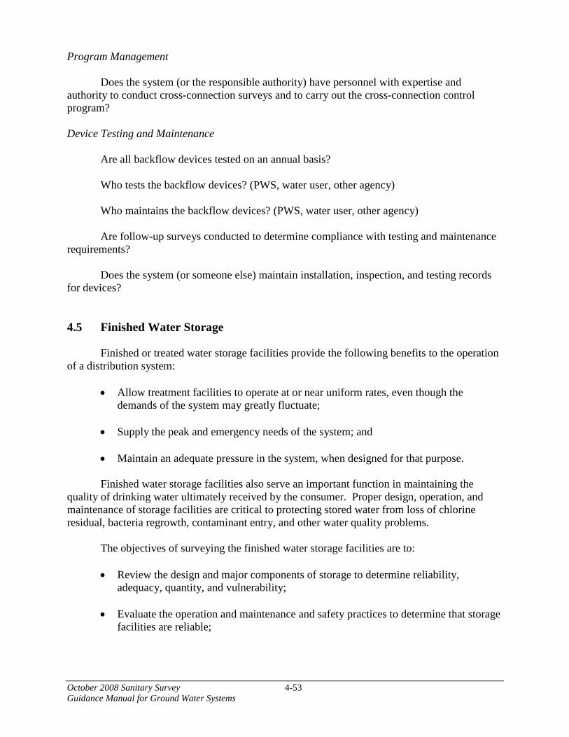
October 2008 Sanitary Survey 4-53 Guidance Manual for Ground Water Systems
Program Management Does the system (or the responsible authority) have personnel with expertise and
authority to conduct cross-connection surveys and to carry out the cross-connection control program?
Device Testing and Maintenance
Are all backflow devices tested on an annual basis? Who tests the backflow devices? (PWS, water user, other agency) Who maintains the backflow devices? (PWS, water user, other agency) Are follow-up surveys conducted to determine compliance with testing and maintenance
requirements? Does the system (or someone else) maintain installation, inspection, and testing records
for devices?
4.5 Finished Water Storage
Finished or treated water storage facilities provide the following benefits to the operation of a distribution system:
• Allow treatment facilities to operate at or near uniform rates, even though the demands of the system may greatly fluctuate;
• Supply the peak and emergency needs of the system; and
• Maintain an adequate pressure in the system, when designed for that purpose.
Finished water storage facilities also serve an important function in maintaining the quality of drinking water ultimately received by the consumer. Proper design, operation, and maintenance of storage facilities are critical to protecting stored water from loss of chlorine residual, bacteria regrowth, contaminant entry, and other water quality problems. The objectives of surveying the finished water storage facilities are to:
• Review the design and major components of storage to determine reliability,
adequacy, quantity, and vulnerability;
• Evaluate the operation and maintenance and safety practices to determine that storage facilities are reliable;

October 2008 Sanitary Survey 4-54 Guidance Manual for Ground Water Systems
• Recognize any sanitary risks attributable to storage facilities (UFTREEO Center, 1998); and
• Determine the potential for degradation of the stored water quality. To accomplish these objectives, the surveyor should complete the following tasks:
• Review the information available from State and water system files.
• Perform field surveys to verify the file information, to assess the tank’s structural
condition, operational readiness, site security and potential sanitary risks.
• Check that maintenance identified in storage facility inspections has been completed.
• Discuss current operation and maintenance (O&M) procedures with water system staff including safety procedures.
Safety is an important consideration in conducting field surveys of storage facilities.
Potential safety hazards include confined space issues; exposure to lead during removal of lead-based coatings; falls or scrapes when climbing the tank; and insect bites. In some cases, the results of a recent inspection done by a qualified tank contractor may provide the surveyor with the necessary information without climbing the tank. Some States do not allow their staff to climb water towers, so surveyors may need to rely on information from tank contractor inspections, ground level observations, and conversation with water system operators to verify file information and assess the adequacy and condition of storage facilities. Surveyors who are expected to climb storage tanks as part of the tank inspection should receive written inspection procedures and training in appropriate safety procedures (e.g., use of safety belts and cables).
Specific items to be addressed in the sanitary survey are outlined in the sections below. 4.5.1 Storage Facility Inventory
Before going into the field, the surveyor should obtain the information available on all the finished water storage facilities for the water system from the State’s files, including the last sanitary survey. The State information should include the type, location, age and installation date, material of construction, storage volume, operating levels and controls. In addition, the surveyor should review applicable regulatory requirements and industry guidance.
Upon arriving at the facility, the surveyor should review the available data with system personnel to determine if the information is current. If there have been any changes, the surveyor should obtain an updated listing of finished water storage facilities, so that they may be all inspected during the survey. The system may have historical records that can provide additional information on storage facility design, construction, operation, maintenance and current physical condition. These records may include as-built construction drawings, inspection reports, maintenance records, water quality data, sediment sampling data, operational data and customer complaint records from the facilities’ service area.
October 2008 Sanitary Survey 4-55 Guidance Manual for Ground Water Systems
Regulatory Requirements and Industry Guidelines
Design and Construction. Recommended Standards for Water Works (2007) provides suggested design criteria for tank storage capacity, siting considerations, tank appurtenances and safety features.
Operations. Regulatory requirements pertaining to tank operations may include operator certification requirements, water turnover rates, and emergency operating plans. There are no specific Federal regulatory requirements on water turnover rates in storage facilities, but industry guidance suggests that a complete water turnover be accomplished every three to five days (Kirmeyer et al. 1999). Most States require that a water system maintain an emergency operations plan, which should include emergency operating procedures for storage facilities.
Maintenance and disinfection procedures. There are no Federal regulatory requirements for tank maintenance or cleaning procedures. Many States recommend adhering to AWWA Standards, NSF Standard 61, and Recommended Standards for Water Works (2007). AWWA Standards and guidance that apply to finished water storage facilities include:
• C652 Disinfection of Water Storage Facilities;
• D100 Welded Steel Tanks for Water Storage;
• D102 Coating Steel Water-Storage Tanks;
• D103 Factory-Coated Bolted Steel Tanks for Water Storage;
• D120 Thermosetting Fiberglass-Reinforced Plastic Tanks;
• G200 Distribution Systems Operation and Management; and
• AWWA Manual M42 Steel Water Storage Tanks.
Water systems should have a plan and schedule for cleaning and inspecting their storage facilities that provide for adequate protection of water and meet any State regulations or guidelines. An AwwaRF guidance manual suggests that covered facilities be cleaned every three to five years (Kirmeyer et al. 1999).
Some States have environmental regulations that govern discharge of chlorinated water
from storage facilities. Dechlorination of the water may be required prior to disposal.
Water Quality Monitoring. Federal drinking water regulations do not specifically require the utility to monitor water quality conditions within storage facilities. Most States do not require routine water quality monitoring within storage facilities, but some States require that water samples be free of coliform bacteria before a storage facility is returned to service after maintenance. Industry guidelines such as the AwwaRF guidance manual, Maintaining Water Quality in Finished Water Storage Facilities (Kirmeyer et al. 1999) recommend monitoring within the storage facility to assess stored water quality.

October 2008 Sanitary Survey 4-56Guidance Manual for Ground Water Systems
Safety. Several OSHA regulations apply to finished water storage facilities:
• OSHA Fall Protection Standards (http://www.osha.gov/confinedspaces/index.html).
• Lead Exposure in Construction (29CFR1926.62)(http://www.osha.gov/pls/oshaweb/owadisp.show_document?p_table=STANDARDS&p_id=10641).
• Confined Space Rule (29 CFR 1910.146)(http://www.osha.gov/SLTC/confinedspaces/standards.html).
Types of Finished Water Storage Facilities
There are several types of finished water storage facilities that can be categorized by their physical shape, dimensions and location.
Clearwells and Other Chlorine Contact Facilities – These storage facilities are usually considered to be part of the water treatment plant, and not distribution storage. Some utilities have storage facilities at or near the water treatment plant that serve both as storage and for achieving disinfection contact time.
Ground Storage Tanks – Ground storage tanks are used to reduce treatment plant peak production rates and are also used as a source of supply for re-pumping to a higher pressure level. If located at a sufficiently high elevation, a pumping station will not be needed and water can flow by gravity to the distribution system. Ground storage tanks can be below ground, partially below ground, or constructed above ground level in the distribution system. Covered reservoirs may have concrete, structural metal, or flexible covers.
Elevated Storage Tanks - Elevated storage tanks are used to supply peak demand rates and equalize system pressures. The most common types of elevated storage are elevated steel tanks and standpipes. A standpipe is a tall cylindrical tank normally constructed of steel, although concrete may be used as well. It functions somewhat as a combination of ground and elevated storage. Only the portion of the storage volume of a standpipe that provides the required system pressure is considered useful storage for pressure equalization purposes. The lower portion of the storage acts to support the useful storage and to provide a source of emergency water supply. Many standpipes were built with a common inlet and outlet. Elevated tanks are generally located at some distance from the pump station in areas having low system pressures during high water use periods.
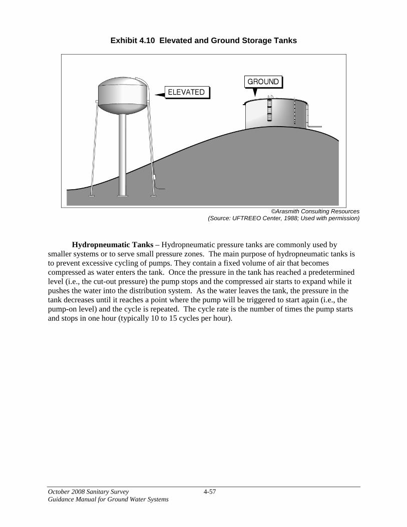
October 2008 Sanitary Survey 4-57 Guidance Manual for Ground Water Systems
Exhibit 4.10 Elevated and Ground Storage Tanks
©Arasmith Consulting Resources (Source: UFTREEO Center, 1988; Used with permission)
Hydropneumatic Tanks – Hydropneumatic pressure tanks are commonly used by smaller systems or to serve small pressure zones. The main purpose of hydropneumatic tanks is to prevent excessive cycling of pumps. They contain a fixed volume of air that becomes compressed as water enters the tank. Once the pressure in the tank has reached a predetermined level (i.e., the cut-out pressure) the pump stops and the compressed air starts to expand while it pushes the water into the distribution system. As the water leaves the tank, the pressure in the tank decreases until it reaches a point where the pump will be triggered to start again (i.e., the pump-on level) and the cycle is repeated. The cycle rate is the number of times the pump starts and stops in one hour (typically 10 to 15 cycles per hour).

October 2008 Sanitary Survey 4-58 Guidance Manual for Ground Water Systems
Exhibit 4.11 Typical Hydropneumatic Tank Installation
©Arasmith Consulting Resources (Source: UFTREEO Center, 1988; Used with permission)
4.5.2 Capability and Capacity 4.5.2.1 Capability
Water systems should have developed and implemented comprehensive programs to
operate and maintain finished water storage facilities. The existence of written procedures and policies is especially important for storage facilities to facilitate inter-departmental communications since personnel from several different departments may share responsibility (e.g., operations, maintenance, engineering, laboratory). The person conducting the sanitary survey should discuss the system’s capability for proper operation and maintenance of their storage facility by confirming the acceptability of the system’s historical records and recordkeeping practices; inspection program; standard operating practices; maintenance program; and safety program.
Inspection Program
Storage facilities and the grounds surrounding them should be routinely surveyed to
prevent water quality problems. It is recommended that water utilities have comprehensive inspections of the structural condition of their storage facilities every three to five years, including areas of the facility that are not normally accessible from the ground. A comprehensive inspection should include a close evaluation of the condition of interior and exterior coatings, foundation, ladder, vent, hatch, overflow pipe, screens, cathodic protection system, and the depth of the interior sediment.
Standard Operating Procedures (SOPs)
Water utilities are encouraged to have written SOPs for operating their system under
normal and emergency conditions. SOPs are an effective way to prevent miscommunication
October 2008 Sanitary Survey 4-59 Guidance Manual for Ground Water Systems
among staff responsible for different aspects of a system’s operations and management. SOPs usually include:
• System description with map;
• Facility descriptions;
• Water quality goals;
• Monitoring plan;
• Description of the operations procedures;
• List of responsible parties for each activity; and
• List of emergency contact people (Kirmeyer et al., 1999).
Excessive water age results from under utilization (i.e., lack of flow) and short circuiting
within the reservoir. Distribution system operations staff have two effective tools to reduce water age: turn the water over on a routine basis and fluctuate the water levels widely (Kirmeyer et al. 1999). In addition to establishing a theoretical turn over rate (i.e., once in three, five, or seven days); the utility may need to establish a water level fluctuation approach that will turn over a majority of the water in one continuous operation. This is especially true for storage facilities with common inlets and outlets such as standpipes. Simply withdrawing 10 percent or 20 percent of the volume of a standpipe each day and immediately refilling could still leave a major portion of storage volume stagnant or poorly mixed for long periods. Thus, if feasible, it would be advisable to fluctuate the water level more widely with a target withdrawal of 60 percent of the volume in one day and then refill it the next (Kirmeyer et al., 1999). This must be balanced with the need to maintain adequate pressures and emergency storage.
Maintenance Program
Does the system follow State requirements or State/industry guidelines for cleaning,
interior coatings, and return to service disinfection and testing? Has the water system established responsibilities and communication procedures regarding
finished water storage facility operation, maintenance, water quality etc.?
Safety Program Does system follow OSHA and other safety standards for fall protection, confined space
and lead exposure? Does the system have a written program and maintain appropriate permits for confined
space entry?

October 2008 Sanitary Survey 4-60 Guidance Manual for Ground Water Systems
Training Programs
Does system provide appropriate training for inspection and maintenance staff including training on OSHA standards, use of safety equipment, and handling of disinfection chemicals? 4.5.2.2 Storage Capacity
Storage tank capacities should be adequate to meet the water demands of the system,
should meet applicable State requirements and industry standards, and be consistent with accepted engineering practice. For example, the total capacity of both ground and elevated storage tanks could be based on a recommended level of 200 gallons per connection. For elevated storage tanks alone, a recommended capacity of 100 gallons per connection is often used. For systems using hydropneumatic tanks instead of elevated tanks, recommended capacities are 20 gallons per connection with ground storage and 50 gallons per connection without ground storage. Capacities for pumps and pumping equipment associated with storage tanks are discussed in Section 4.6.
Suggested assessment criteria for the capacity of storage tanks include:
In case of elevated storage tanks, are tanks properly sized and elevated to assure adequate pressures throughout the distribution system? The water tank should be properly sized and elevated to produce pressures of at least 35
psi at the lowest operating level of the tank. Operating pressures in the distribution system should not be allowed to exceed 100 psi (Recommended Standards for Water Works, 2007).
Does the system have adequate storage capacity to meet fire flow requirements, emergency storage requirements, system pressures and other site-specific conditions? For systems that do not provide fire protection, the minimum storage capacity should be
equal to the average day demand or lower if source and treatment facilities have sufficient capacity and standby power to help meet peak demands.
For hydropneumatic tanks, the gross storage capacity should equal approximately ten
times the largest pump capacity (Recommended Standards for Water Works, 2007). For example, a 2,500 gallon tank would be advised for a system using a 250 gpm pump. The sizing of the hydropneumatic tank is also affected by the system’s ability to meet maximum demand conditions. 4.5.3 Design and Construction
The surveyor should examine the design criteria of the storage tanks to assess their potential to meet the water demands of the distribution system and retain structural integrity. Design and construction standards need to be appropriate for the intended use of a storage tank.

October 2008 Sanitary Survey 4-61 Guidance Manual for Ground Water Systems
The series of standards used to design tanks with all the necessary components identified is usually the AWWA D-100 series. The construction material for the tank should also be examined for structural integrity as well as for any sanitary hazards. For example, opportunistic pathogens, such as Klebsiella can grow to high levels in unlined wooden storage tanks. Exhibit 4.12 provides a schematic of the various components of a storage tank. The following is a listing of recommended criteria for a treated water storage tank, whether it is a ground or elevated storage tank (Kirmeyer et al., 1999):
• Roof sloped to prevent standing water;
• No leakage through the roof;
• A lockable access hatch on the roof, with a raised curb (Ten States standards type);
• Vent on the roof with openings that face downward, with a fine corrosion resistant
screen;
• Water level measurement device;
• Overflow that terminates above ground with a hinged and weighted flap on the end;
• Inlet and outlet piping located to ensure proper circulation of water; • Drain (not connected to storm or sanitary sewer) for maintenance and cleaning;
• Access openings on the side (at least two);
• Access ladder with proper safety equipment;
• Valves on inlet and outlet for isolation;
• Bypass around the tank for maintenance;
• Control system to maintain water level in tank; and
• Alarm system for high/low water levels.

October 2008 Sanitary Survey 4-62 Guidance Manual for Ground Water Systems
Exhibit 4.12 Components of a Storage Tank
©Arasmith Consulting Resources (Source: UFTREEO, 1998; Used with permission)
Does the tank have all the recommended components listed above? Are these components in good condition?
The inspection items listed above are important for maintaining the structural integrity of the tank and maintaining water quality.
The design components for hydropneumatic tanks are significantly different than a ground or elevated storage tank. Hydropneumatic tank systems can use any of several types of pressure storage tanks. Exhibit 4.13 depicts the various types of pressure tanks available. Many very small ground water systems use vertical tanks like the two on the right side of the exhibit.
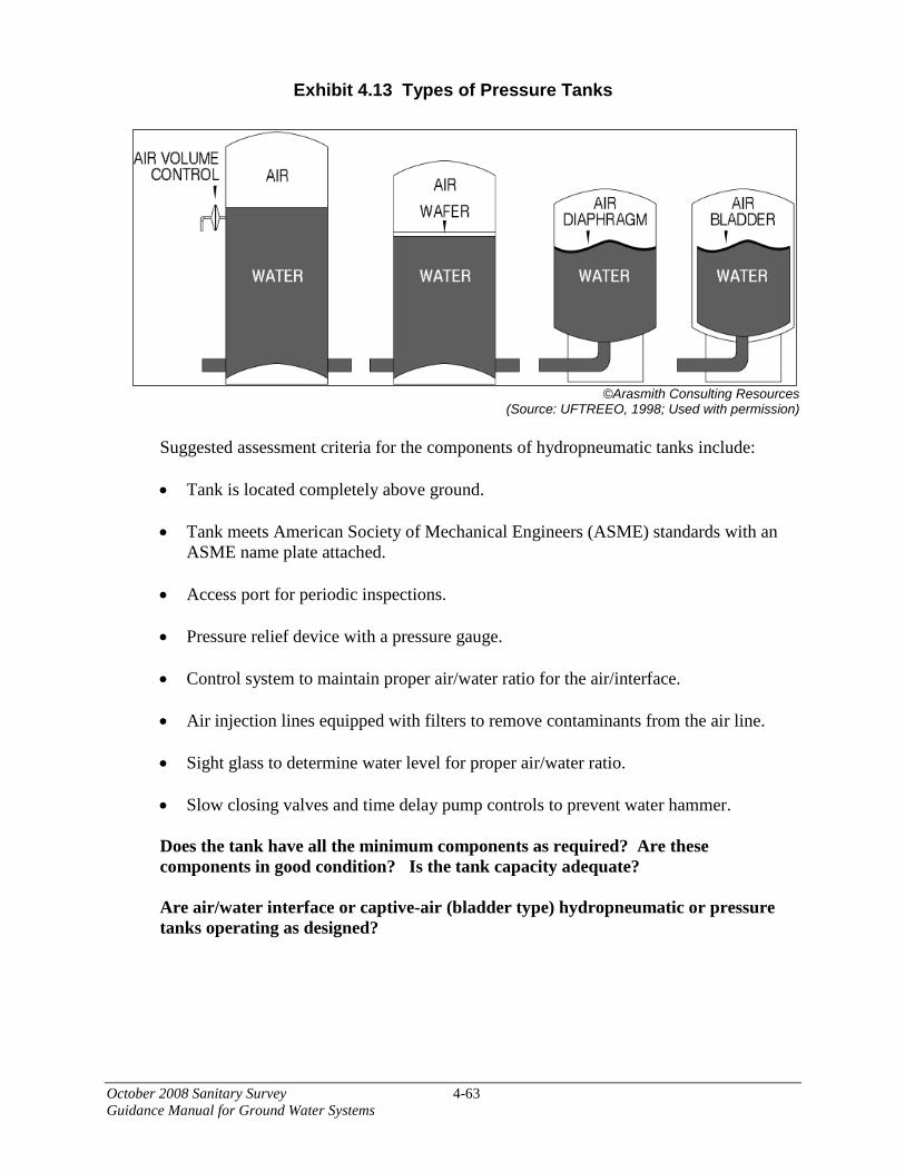
October 2008 Sanitary Survey 4-63 Guidance Manual for Ground Water Systems
Exhibit 4.13 Types of Pressure Tanks
©Arasmith Consulting Resources (Source: UFTREEO, 1998; Used with permission)
Suggested assessment criteria for the components of hydropneumatic tanks include: • Tank is located completely above ground.
• Tank meets American Society of Mechanical Engineers (ASME) standards with an
ASME name plate attached.
• Access port for periodic inspections.
• Pressure relief device with a pressure gauge.
• Control system to maintain proper air/water ratio for the air/interface.
• Air injection lines equipped with filters to remove contaminants from the air line.
• Sight glass to determine water level for proper air/water ratio.
• Slow closing valves and time delay pump controls to prevent water hammer.
Does the tank have all the minimum components as required? Are these components in good condition? Is the tank capacity adequate? Are air/water interface or captive-air (bladder type) hydropneumatic or pressure tanks operating as designed?
October 2008 Sanitary Survey 4-64 Guidance Manual for Ground Water Systems
Additional criteria to consider during the sanitary survey when evaluating a water system’s
tanks include:
Does the system maintain adequate system pressure? Is the storage system designed for direct plumbing or floating on the distribution system (is a reliable hydraulic residence time achieved if the tank is being used for disinfection contact time)? Do any tanks operate below the system hydraulic grade line (making it more difficult for water in the tanks to turn over)? Are newly constructed facilities surveyed and documented on as built drawings? Are remote storage facilities regularly surveyed or routinely monitored (with provisions for sample collection)?
Are overflow, drain lines and air vents covered and screened to prevent animal/insect entry? Are they turned downward and terminated at least 2 pipe diameters above the ground? Do tanks have design features that allow maintenance to occur? Can the tanks be isolated from the system? Is there a bypass line around the tank for maintenance? Access openings on side of tank? Separate drain for maintenance and cleaning? Tank drain pipe allows tank to be drained without causing pressure loss in the distribution system? Is there evidence of spalling or rebar failure on concrete tanks? Accessible roof hatches? Are access ladders equipped with proper safety equipment? Do tanks have design features that prevent contamination from external sources? All storage facilities covered? Roof sloped to prevent standing water?

October 2008 Sanitary Survey 4-65 Guidance Manual for Ground Water Systems
Is roof watertight? Are all pipe and equipment penetrations into the roof watertight? Is the tank protected against natural hazards (i.e., wind, seismic events)?
Are wooden or prefabricated tanks secured to a foundation? Ground level elevation of standpipes and reservoirs above the 100 year flood elevation and placed at normal ground surface? Drains and overflow pipe are not directly connected to sewers or storm drains? Do tanks have design features that prevent degradation of water quality? Inlet and outlet piping located to ensure proper circulation of water? Are there any physical features on or around the site that could damage the tank? Is the site well-maintained (i.e., vegetation, roadways, paths)? Is there adequate surface drainage around tank? Is the site subject to flooding? Are there any structural gaps in the storage facilities that would allow untreated water or contaminants to enter the storage facility? Is there evidence of exterior or interior corrosion? Is cathodic protection provided for steel tanks? Has the installation of appurtenances, including antennae, damaged tank structure, coatings or affected water quality?
4.5.4 Site Security The surveyor should assess the site security of the water system to determine the potential for intruder access. Any potable water storage tank should be enclosed by an intruder-resistant fence with lockable access gates. In addition, all access hatches should be locked. The surveyor should assess the site security of the water system to determine the potential for intruder access. The Guidelines for Physical Security of Water Utilities (AWWA, 2006), provides additional guidance.
Suggested assessment criteria for site security include: Is the fence surrounding the tank site intruder-resistant?
Are roof hatches locked with a raised curb and watertight seal?
October 2008 Sanitary Survey 4-66 Guidance Manual for Ground Water Systems
Are access ladders inaccessible to the public? Are valve pits vandal proof? Have there been any incidents at the system’s storage facilities where site security was breached, accidents occurred, or water quality was compromised? Are there any tank sites with particular security or vandalism issues? Do access manholes, buildings and any other structures have locked entry ways?
4.6 Pumps
In addition to transporting water through the system, pump applications include chemical feed systems, sludge removal, air compression and sampling (UFTREEO Center, 1998). For a given application, there could be several viable pumping options. However, there are usually only one or two types of pumps that will be the best fit for the intended use. In this section, the prime movers of water will be discussed. There are numerous applications for other types of pumps in other sections of this document.
The objectives of surveying the pumps/pump facilities and controls are to: • Review the design, uses, and major components of water supply pumps;
• Evaluate the operation and maintenance as well as safety practices to determine that
water supply pumping facilities are reliable; and
• Recognize any sanitary risks attributable to water supply pumping facilities (UFTREEO Center, 1998).
4.6.1 Typical Pumps
Before going into the field, the surveyor should obtain the information available on all the pumping facilities for the water system from the State’s files, including the last sanitary survey. The information on pumping facilities should include the type, location, age and installation date, and design conditions of the system’s pump(s), pumping facilities, and controls.
In addition, the surveyor should review the regulatory requirements for pumps, if any, to assist in the evaluation of the pumping facilities. The regulatory requirements could include, but not necessarily be limited to, State rules and regulations, American National Standards Institute/National Sanitary Foundation (ANSI/NSF) Standards 60 and 61, as well as appropriate guidance manuals.
Upon arriving at the facility, the surveyor should review the available data on pumps with system personnel to determine if the information is current. If there have been any changes, the surveyor should obtain an updated listing of the pumps used within the system, so that they may
October 2008 Sanitary Survey 4-67 Guidance Manual for Ground Water Systems
be all inspected during the survey. For most systems, the surveyor will either have a list of pumps or pump data from a previous sanitary survey or have a list supplied by the system operator. If a system does not have a pump listing, the surveyor should work with the system operator to develop a new listing so that all pumps may be inspected during the survey.
There are two main classes of pumps used in water systems.. They are positive displacement pumps and centrifugal pumps. Positive displacement pumps deliver water at a constant rate regardless of the pressure it must overcome (USEPA 1991). Typical pumps that can be found in a water system are:
• Helical or Spiral Rotor Pump – This pump consists of a shaft with a spiral surface that rotates in a rubber sleeve. Water is trapped between the shaft depressions and the sleeve and is forced to the upper end of the sleeve as the shaft rotates.
• Regenerative Turbine Pump – This pump contains an impeller or a rotating wheel
with fins or little buckets on its outer edge. The rotating wheel is inside a stationary enclosure (cast). As the wheel rotates at a high speed, it forces water through the pump cast (also called raceway) at a pressure that is several times that which can be generated by centrifugal mechanisms (USEPA, 1991).
• Reciprocating Pump – This pump consists of a piston moving back and forth in a
cylinder. As the cylinder is driven back and water is driven into the cylinder, the intake valve closes and forces the water through the check valve. As the cylinder is driven forward, the water is discharged through a discharge pipe while the check valve is closed (USEPA, 1991).
• Positive Displacement Pump – This pump is typically used for online chemical
application (i.e., application of chemicals into pressurized water line).
Centrifugal pumps are used when an even flow rate is needed to meet the demands placed on it. The operating curve for a centrifugal pump shows that the pumping rate varies with the discharge pressure of the water at discharge from the pump (i.e., as the discharge pressure increases, the rate of pumping decreases).
With a rotating impeller (i.e., rotor blade) driven by a power source, such as a motor, a centrifugal pump increases the velocity of the water and discharges it into the pump casing. In the pump, the velocity of the water is converted to pressure. Typically, a centrifugal pump has only one impeller, and it is called a single-stage pump. If more pressure is needed, multiple impellers or multi-stages are used to generate the necessary discharge pressure at the pump. Multiple impellers only increase the discharge pressure, not the pumping rate (UFTREEO Center, 1998).
A centrifugal pump cannot create a negative pressure at the suction inlet to pull water into the pump, like a self-priming pump. Therefore, the pressure at the impeller must be positive (i.e., water level is higher than the impeller) in order for the pump to operate.
There are three types of centrifugal pumps that are normally used in a water system for the many pumping applications: submersible, vertical (lineshaft) turbine, end suction (close
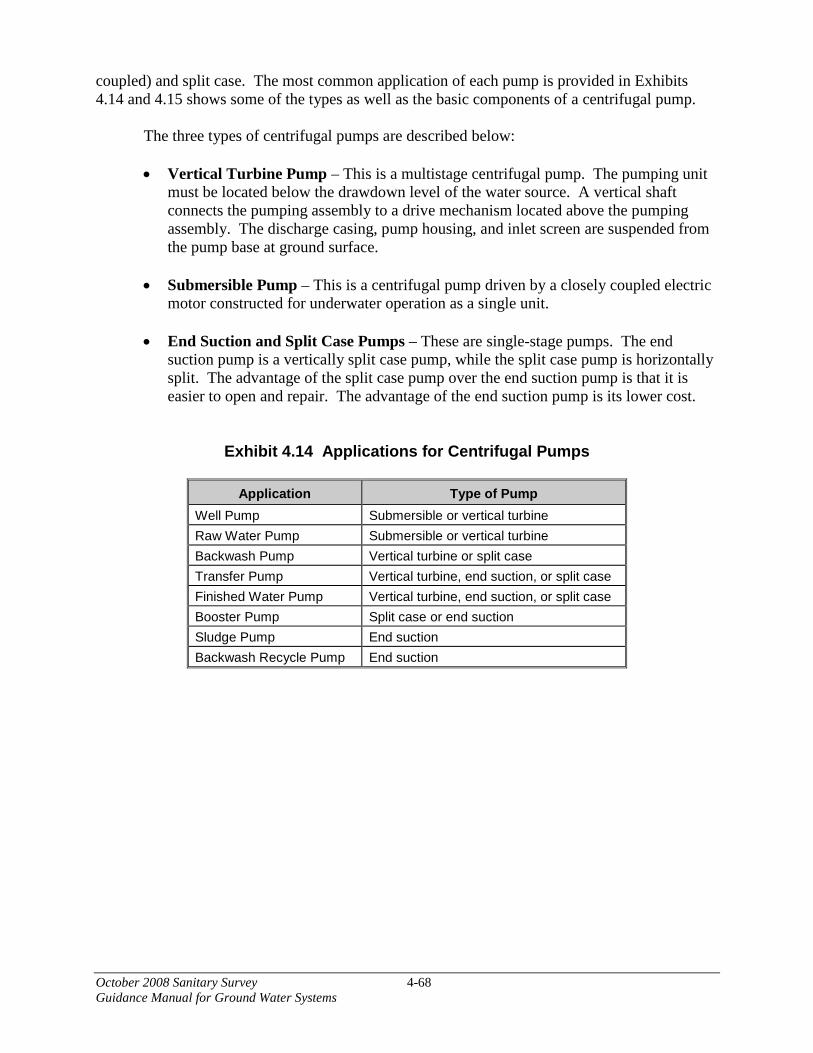
October 2008 Sanitary Survey 4-68 Guidance Manual for Ground Water Systems
coupled) and split case. The most common application of each pump is provided in Exhibits 4.14 and 4.15 shows some of the types as well as the basic components of a centrifugal pump.
The three types of centrifugal pumps are described below:
• Vertical Turbine Pump – This is a multistage centrifugal pump. The pumping unit must be located below the drawdown level of the water source. A vertical shaft connects the pumping assembly to a drive mechanism located above the pumping assembly. The discharge casing, pump housing, and inlet screen are suspended from the pump base at ground surface.
• Submersible Pump – This is a centrifugal pump driven by a closely coupled electric
motor constructed for underwater operation as a single unit. • End Suction and Split Case Pumps – These are single-stage pumps. The end
suction pump is a vertically split case pump, while the split case pump is horizontally split. The advantage of the split case pump over the end suction pump is that it is easier to open and repair. The advantage of the end suction pump is its lower cost.
Exhibit 4.14 Applications for Centrifugal Pumps
Application Type of Pump Well Pump Submersible or vertical turbine Raw Water Pump Submersible or vertical turbine Backwash Pump Vertical turbine or split case Transfer Pump Vertical turbine, end suction, or split case Finished Water Pump Vertical turbine, end suction, or split case Booster Pump Split case or end suction Sludge Pump End suction Backwash Recycle Pump End suction
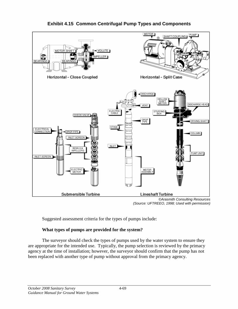
October 2008 Sanitary Survey 4-69 Guidance Manual for Ground Water Systems
Exhibit 4.15 Common Centrifugal Pump Types and Components
©Arasmith Consulting Resources
(Source: UFTREEO, 1998; Used with permission)
Suggested assessment criteria for the types of pumps include:
What types of pumps are provided for the system?
The surveyor should check the types of pumps used by the water system to ensure they are appropriate for the intended use. Typically, the pump selection is reviewed by the primacy agency at the time of installation; however, the surveyor should confirm that the pump has not been replaced with another type of pump without approval from the primacy agency.
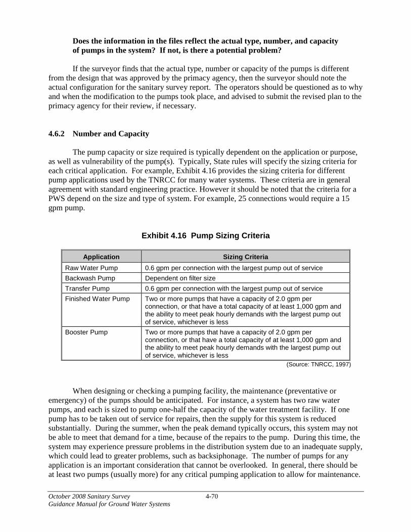
October 2008 Sanitary Survey 4-70 Guidance Manual for Ground Water Systems
Does the information in the files reflect the actual type, number, and capacity of pumps in the system? If not, is there a potential problem?
If the surveyor finds that the actual type, number or capacity of the pumps is different
from the design that was approved by the primacy agency, then the surveyor should note the actual configuration for the sanitary survey report. The operators should be questioned as to why and when the modification to the pumps took place, and advised to submit the revised plan to the primacy agency for their review, if necessary. 4.6.2 Number and Capacity
The pump capacity or size required is typically dependent on the application or purpose, as well as vulnerability of the pump(s). Typically, State rules will specify the sizing criteria for each critical application. For example, Exhibit 4.16 provides the sizing criteria for different pump applications used by the TNRCC for many water systems. These criteria are in general agreement with standard engineering practice. However it should be noted that the criteria for a PWS depend on the size and type of system. For example, 25 connections would require a 15 gpm pump.
Exhibit 4.16 Pump Sizing Criteria
Application Sizing Criteria Raw Water Pump 0.6 gpm per connection with the largest pump out of service Backwash Pump Dependent on filter size Transfer Pump 0.6 gpm per connection with the largest pump out of service Finished Water Pump Two or more pumps that have a capacity of 2.0 gpm per
connection, or that have a total capacity of at least 1,000 gpm and the ability to meet peak hourly demands with the largest pump out of service, whichever is less
Booster Pump Two or more pumps that have a capacity of 2.0 gpm per connection, or that have a total capacity of at least 1,000 gpm and the ability to meet peak hourly demands with the largest pump out of service, whichever is less
(Source: TNRCC, 1997)
When designing or checking a pumping facility, the maintenance (preventative or emergency) of the pumps should be anticipated. For instance, a system has two raw water pumps, and each is sized to pump one-half the capacity of the water treatment facility. If one pump has to be taken out of service for repairs, then the supply for this system is reduced substantially. During the summer, when the peak demand typically occurs, this system may not be able to meet that demand for a time, because of the repairs to the pump. During this time, the system may experience pressure problems in the distribution system due to an inadequate supply, which could lead to greater problems, such as backsiphonage. The number of pumps for any application is an important consideration that cannot be overlooked. In general, there should be at least two pumps (usually more) for any critical pumping application to allow for maintenance.
October 2008 Sanitary Survey 4-71 Guidance Manual for Ground Water Systems
Suggested assessment criteria for the capacity of pumps include:
What are the capacities of the pumps? How many pumps are located at each facility?
The capacity of a pump is sometimes listed on the motor plate along with the horsepower,
motor speed and other pertinent information. The surveyor should note the capacity or other information provided on each pump and compare this information to the approved design for the pump station. The actual capacity of the pump may be less than the rated capacity as a result of wear or an increase in the operating head. Actual pump capacity can be measured if an accurate flow metering device is installed on the pump discharge line.
What is the firm capacity and the total capacity of each pumping facility?
The surveyor should confirm that the firm capacity of the pumping facility, or the capacity of the facility with its largest pump out of service is consistent with the minimum capacity approved by the primacy agency. The firm capacity of any pumping facility should be determined with the largest pump out of service to ensure that adequate capacity is available to meet all expected demand/supply conditions. The total capacity of a pumping facility is the sum of the capacities of all associated pumps and is larger than firm capacity.
Is priming adequate?
The surveyor should ensure that prime waters must not be of a lesser sanitary quality than that of the water pumped. It should be ensured that there are adequate backflow prevention devices. When an air-operated ejector is used, the screened intake should draw clean air from a point at least 10 feet above the ground or other possible sources of contamination (Recommended Standards for Water Works, 2007).
Are the pumps compliant with State rules?
If the surveyor finds that the actual type, number, or capacity of the pumps is different from the design that was approved by the primacy agency, then the surveyor should note the actual configuration for the sanitary survey report. The operators should be questioned as to why and when the modification to the pumps took place, and advised to submit the revised plan to the primacy agency for their review, if necessary.
Are backup units and critical spare parts available to assure that down time is minimal?
The surveyor should ensure that, in the event of equipment failure, critical pump parts are available. Water systems should either have the equipment in their inventory, have access to vendors with equipment and parts housed locally, or have some sort of mutual aid agreement with neighboring utilities.

October 2008 Sanitary Survey 4-72 Guidance Manual for Ground Water Systems
4.6.3 Routine Maintenance/Lubrication/Exercise
The surveyor should ask whether the system has a pump maintenance program and how it is being implemented. Backup pumps should be exercised routinely and all pumps should be operational. Pumps should be accessible so they can be properly maintained and repaired without physically disrupting other elements of the water system. Most well houses will have a hatch in the roof or a similar structural arrangement to provide access to the well in case the submersible pump needs to be removed.
For any wells where contact is made with the water, food grade lubricants should be used. Many States require lubricants used under such conditions (e.g., oi-lubricated well shaft bearings, check valves) to be ANSI or NSF-approved. This is not usually a requirement for lubricants that do not come in contact with the water. All lubricants should be applied according to manufacturer’s specifications. 4.6.4 Housing
Pumps are found in a variety of buildings including well houses, treatment plants and booster stations. As part of the sanitary survey, these buildings should be surveyed to ensure they are providing secure physical protection to the pumps. A pumping station should be at least three feet above flood level, and the land around it should be graded so that surface runoff drains away from the building (Recommended Standards for Water Works, 2007). Inside, floor drains should be able to accommodate a large volume of water due to a pipe break in the building. Below-ground pump stations should be checked to make sure they are dry and properly sealed so that water cannot seep through walls or enter from the surface. Dry pits should include a sump and sump pump. Pump stations should be properly ventilated and electrical controls and motors should not be subject to flooding. Sufficient protection should be provided to prevent freezing/heating of pipes, pumps, valves, and other equipment. 4.6.5 Site Security
Pumping stations and well houses should be secure. Doors and windows should be locked and no unauthorized entry should be allowed. Any electrical panels, switches and valves located outside of the building should be secured and within a fenced perimeter. 4.6.6 Cross Connections
When pumps are being inspected during the survey, any situation where there is a potential for backflow should be identified. Cross connections can be found in
• Water lubricated bearing systems,
• Pump seal water lubrication systems,
October 2008 Sanitary Survey 4-73 Guidance Manual for Ground Water Systems
• Cooling water lines for emergency generators,
• Air/vacuum release discharge lines, and
• Priming lines for suction-lift pumps (USEPA, 2003a).
Situations where there is the potential for backflow should be equipped with an air gap or an approved backflow prevention device. 4.7 Emergency Power
During a sanitary survey, the surveyor should consider whether a system needs auxiliary power at critical facilities to maintain a reliable source of potable water to its customers. Systems with auxiliary power units should be exercising them routinely, and operators should have a clear understanding of what the unit powers and how it is activated. The person conducting the sanitary survey should establish whether auxiliary power is triggered manually or automatically, and that the system has a reliable program in place for switching to the emergency power supply.
Suggested assessment criteria for evaluating emergency power include:
Is Auxiliary Power Needed? Auxiliary power may be necessary for the continuous operation of a water system. When
assessing whether a system needs auxiliary power, consider how long the system can reliably continue to provide water when it loses power. Also consider how frequently the system loses power and the duration of power outages. Systems with limited storage may not be able to sustain water production for very long. Systems relying on pumps to move water to their distribution system may not be able to provide sufficient water and maintain adequate pressure throughout their distribution systems.
How is it Activated? Auxiliary power should be automatically activated when the primary power supply is
lost. There should be a switch that automatically transfers the load to the auxiliary power unit. An alarm should notify the operator when the auxiliary power unit is turned on. Although auxiliary power should be automatically activated, operators should have the capability of manually operating their generators.
Small ground water systems that do not have generators on site should, at a minimum, be
able to hook up a generator quickly and safely. Pump houses or treatment plants can be wired so generators can be connected quickly at the time of the power outage. If such an arrangement is observed during the sanitary survey, information should be gathered about the location of the generator that would be used during an outage and the system’s plan for responding and installing the generator in a way that does not result in interruption of service.
October 2008 Sanitary Survey 4-74 Guidance Manual for Ground Water Systems
What Does It Supply Power For? What Level of Production and Supply Does the Emergency Power Have Capacity for? The operator should know what steps of water production, treatment and delivery would
be powered by emergency power in the case of a power outage. During the sanitary survey, the surveyor should determine whether the quantity and quality of water needed by the system’s customers could be maintained and for how long. In addition to the well pump, auxiliary power should operate any automatic controls and chemical feed systems related to the source that is being pumped. Lights, heat and ventilation in the pump house and treatment plant should also be provided with emergency power.
Where is the Fuel Tank? Is there Sufficient Fuel Capacity for the Generator? The person conducting the sanitary survey should locate the fuel tank for the auxiliary
power unit and evaluate if it presents a contamination risk to the well or water that is being stored before or after treatment. Fuel tanks that are stored above ground should be mounted inside a spill containment vessel. Systems that are vulnerable to long power outages (due to severe weather, seismic events) may need fuel supplies for extended periods. For these systems, the surveyor should check that enough fuel is housed to maintain power for the duration of the outage.
Is the Unit Exercised? Auxiliary power units should be exercised at least once a week with an operator in
attendance (USEPA, 2003a) or in accordance with State recommendations or guidelines. It is preferred that the unit be tested under a load during the exercising period, using it as the source of power for any well, treatment and service pumps that would be powered by the unit under emergency conditions. The system should keep records of when and how the unit was exercised, including engine and generator gauge readings, and the surveyor should review these records during the sanitary survey.
Is it Well-Maintained? Regular maintenance of the auxiliary power unit should be provided according to its
manufacturer’s specifications. If the water system has a preventive maintenance program, the surveyor should ask whether the unit is included in the plan. The surveyor should visually check for signs of leaking fluids or lubricants. Any vents in the building housing the unit should be screened to prevent animals from entering and to maintain security. The unit should not be accessible to the public. 4.8 Remote Monitoring/Control/Alarms
Many water systems have some element of remote signaling or operation. Often, a pressure transducer in a storage tank relays a signal that turns the well on or off when the tank level reaches a set level. Some alarms with automatic dialing systems notify operators under emergency conditions. More and more, plants equipped with supervisory control and data acquisition (SCADA) systems are being operated remotely.
October 2008 Sanitary Survey 4-75 Guidance Manual for Ground Water Systems
The person conducting the sanitary survey should understand the roles of any remote control monitoring and alarms at a water system. During the survey, each step of the water system’s operation should be considered and it should be determined whether the step is carried out manually or automatically.
Some assessment criteria to consider when reviewing remote monitoring/control/alarms
include: How are the well pumps controlled? The surveyor should evaluate the control system and determine if it is suitable for its
application. Automatic well pump controls should be equipped with resets and a manual override switch. Pumps supplying water to the distribution system should be equipped with a switch that is triggered based on distribution system pressure.
Are pressure tanks properly plumbed? Pressure tanks whose primary goal is to control the cycling of pumps should be equipped
with a pressure switch that cycles the pump on and off. In order for this to operate correctly, the surveyor should make sure there is no shut-off valve between the pressure switch and the pump. If such a valve is closed, the system will call for water and the pump will begin pumping against a closed valve, most likely damaging the pump.
Are appropriate alarms in place and operational? Well houses, treatment plants and booster stations should be equipped with alarms to
notify their operators when there is a problem with the pumping, treatment or delivery of the water. Some of these alarm systems are much more sophisticated than others. The sanitary surveyor should determine whether the approach a system has to notify its operators in case of an emergency is sufficient for effectively maintaining the operation of that system.
4.9 Monitoring/Reporting/Data Verification
An important part of any industry that produces a product for the consumer is quality control. Quality control is a defined method of checking the product to ensure the consumer it meets or exceeds regulatory requirements as well as their minimum expectations. For the water industry, quality control consists of monitoring water from the source to the tap with in-house as well as outside laboratory testing for confirmation. A monitoring plan provides the operator with data to assist in identifying potential problems and adjusting treatment processes accordingly. For most water systems, regulatory requirements, either State or Federal, dictate the minimum scope of a water quality monitoring plan. Federal regulations require ground water systems to have sampling plans for Total Coliform Rule monitoring and Stage 2 D/DBP Rule monitoring (if applicable).
October 2008 Sanitary Survey 4-76 Guidance Manual for Ground Water Systems
The objectives of surveying the water quality monitoring/reporting/data verification are to:
• Review the water quality monitoring plan of the PWS for conformance with
regulatory requirements;
• Verify that the water quality monitoring plan is being followed by checking test results;
• Verify that all in-house testing as well as equipment and reagents being used conform to accepted test procedures;
• Consider whether any changes in monitoring frequency or location should be
recommended for any contaminant or performance measure;
• Verify the data submitted to the regulatory agency; and
• Evaluate the procedures an operator follows to identify any problems with the process, determine the changes needed to correct the problem, and how adjustments to the process are approved and performed as needed.
If there are no violations or orders, and the required monitoring data are available, it is an
indication that the water system has accepted its assigned responsibilities and is trying to complete its duties accordingly. In general, the surveyor will only have to verify that all sampling and monitoring plans are up-to-date based on the latest regulatory changes, if any. In addition, the surveyor will verify that the data reported to the agency are accurate based on the records kept by the system. Self-monitoring data, monthly operating reports, and daily logs should be reviewed to determine if data are of questionable quality and to evaluate the potential for data falsification.
If there are no violations or orders, but the required monitoring data are not available, it may be difficult to determine if the water system is in compliance with all requirements. Laboratory results for bacteriological, chemical, and radiological monitoring must be kept for specific time periods. The surveyor should review the records to determine if they are kept for the required time period in accordance with each regulation.
The surveyor should carefully review the compliance plans required as a result of a violation or by any orders and verify that the plan is being followed by the system. If all the required monitoring data are not available, the surveyor should determine the reason.
Suggested assessment criteria for data collection include:
Are there any violations or orders for the subject system? If so, is there a compliance plan? If so, what documentation is there to verify compliance? If the system has submitted a compliance plan, the surveyor should take copies of the
plan to verify that the compliance plan is being properly implemented.

October 2008 Sanitary Survey 4-77 Guidance Manual for Ground Water Systems
Have the required sampling plans been submitted and approved? If no, what action is being taken to prepare and submit the plans? Monitoring plans should include the number of samples for each parameter, where
samples are taken, at what time and frequency, who is the person in charge of taking the samples, how they are going to be handled, and who is going to analyze them.
Are all the required monitoring data submitted? If so, do the data appear reasonable? Do the data reported match field log books? If the system has complete, up-to-date, reasonable monitoring data, this is an indication
that it is well managed. However, it is still necessary to verify field log books with submitted reports to rule out any human error in copying the data.
Are records of the monitoring program maintained in an organized and complete manner? The results of the monitoring program should be kept in an organized system and should
be accessible for review. Additional questions that a surveyor should consider during the sanitary survey include: Are treatment and distribution systems monitored (e.g., flows, pressures, tank elevations, pumps) appropriately? Are treatment adjustments made as a result of monitoring results? Are records kept of when and how treatment steps are taken and chemical mixtures (e.g., feed solutions) are prepared?
Does the water system maintain records of preventative maintenance? Does the system document when repairs are made?
4.10 Water System Management/Operations
Management and/or administration is a major factor that affects the performance of a
water system. Management provides the direction, funding, and support that is needed for a PWS to continually supply safe drinking water. For instance, if management does not understand the requirements to produce and provide the quality of drinking water demanded by the consumer, policies may be implemented that hinder the performance of the system and its ability to provide what the consumer wants. Therefore, management and staff need to work together to create an environment that facilitates meeting the goal of providing the best possible quality of drinking water to the consumer.

October 2008 Sanitary Survey 4-78 Guidance Manual for Ground Water Systems
The objectives of surveying the water system management/operation are to: • Review the water quality goals and evaluate any plan(s) the system has to either
accomplish or maintain the stated goals;
• Identify and evaluate the basic information on the system, management, staffing, operations, and maintenance;
• Review and evaluate the plan(s) for safety, emergency situations, maintenance, and security to maintain system reliability; and
• Evaluate the system’s revenue and budget for drinking water to establish the long-term viability of meeting water quality goals (UFTREEO Center, 1998).
4.10.1 Organization and Management
The direction of the system is controlled by the system’s management through the implementation of the budget and policies. During the inspection, the knowledge and experience of these individuals concerning drinking water should be verified. As an example, if the individual at the top of the management structure has little or no experience with a water system, then the implemented budget and policies may reflect that lack of knowledge in determining how the system is operated and maintained. If the individual has the knowledge, then the water system will probably be operated and maintained differently. Therefore, the knowledge and experience that management has with water systems plays an important role in how a system is operated and maintained.
Another impact that management can have is on the morale of the personnel. A positive atmosphere is generated if the management encourages an open dialogue among all levels. This open communication allows workers to express their opinion without fear of reprisal. Encouraging the training and advancement of personnel will also foster positive morale. Although there will be some expenses incurred on the part of the utility, this effort shows that management has an interest in their employees gaining the knowledge necessary to further their careers.
Suggested assessment criteria for system management include: What is the management structure, and who are the individuals at the various levels? What is their experience level with water systems? If the water system has an organizational chart, the surveyor should review the chart to
gain an understanding of the system’s management structure and that individuals are responsible for the different elements of system operation and management. The system needs to have a means of clearly indicating to its own staff who has the responsibility for various functions and who has the authority to make decisions and approve changes to policies, procedures, system operations, and other areas pertinent to treatment plant performance and water supply quality. Personnel in positions of responsibility and management should be experienced with and knowledgeable about drinking water systems and their operation, and have detailed knowledge

October 2008 Sanitary Survey 4-79 Guidance Manual for Ground Water Systems
about their own system and its performance and needs, as well as the regulatory requirements that apply to their system.
Does the water system have a planning process? Does the planning process appear to be implemented? Water system management should be actively involved in planning for the system.
Efforts should include both short-term and long-range planning horizons. The system should have a process for developing and updating plans required under applicable regulations, such as compliance monitoring, source protection, and cross-connection control, as well as other plans integral to a well-functioning water system, such as annual and long-term budgets, equipment purchases, and facility expansion.
Does open, effective communication occur between management and system personnel? Open, effective communication between management and operations staff is integral to
the achievement of a system’s water quality goals for the production of a reliable, high-quality water supply. System personnel should have a means of adequately conveying to management the need for additional equipment and personnel and changes in facility policies and procedures, and for providing input to budgeting and system expansion plans. Management needs to be receptive to staff input and committed to seeking it and using it.
4.10.2 Staff Levels
The surveyor should determine if a list of job descriptions for system personnel is available. The surveyor can use this information to assess whether or not the system seems to have an adequate number of qualified personnel to perform all the necessary work within the system from operations to maintenance. The surveyor should also evaluate the relative distribution of personnel between operations and maintenance positions. If the PWS is operated under contract to a private company, the availability of staff familiar with the system should be assessed. To have a well operated and maintained system, there should be a good mix of responsibilities and personnel, and personnel should have some cross-training between operations and maintenance.
Suggested assessment criteria for system staffing include:
Is the number of personnel adequate to perform the work required? The size of the facility and the types of treatment largely determine what level of
personnel is sufficient. The system should have enough personnel to enable continuous operation of the system at all times, including periods when some staff are absent (e.g., vacations, weekends, holidays). In addition to having an adequate number staff overall, the system should have staff appropriately assigned to operations tasks and maintenance tasks.
October 2008 Sanitary Survey 4-80 Guidance Manual for Ground Water Systems
Is staff coverage adequate given the alarm systems(if any) used by the system? Do variations in supply or finished water quality when the system is unattended indicate the need for additional staff coverage? During periods when the system is unattended or treatment processes are monitored by
alarm systems rather than personnel, fluctuations in supply or finished water quality may occur. The surveyor should evaluate whether the system’s personnel and its use of alarm systems are adequate to promptly address variations in available supply or finished water quality.
Do staff have clearly defined responsibilities and the decision making authority necessary to carry out their responsibilities? System staff need to clearly understand their responsibilities and have the authority to
make any decisions, such as hiring and scheduling personnel and altering elements of treatment plant operation (e.g., equipment shutdowns for maintenance, changes to chemical doses), that are necessary to fulfill their responsibilities in a timely manner. System staff should also sufficiently understand the responsibilities of other personnel so they know who to approach with issues or questions.
Is there cross-training required of the individuals within the system? Some cross-training of employees between operations and maintenance provides the
facility with staffing options during unexpected periods of staff absences (e.g., illnesses) and times when the work load balance between operations and maintenance shifts. Cross-training may also enable staff to better carry out their responsibilities because they have a better understanding of other aspects of water treatment.
4.10.3 Training
Water system personnel are encouraged to receive training on an ongoing basis. Most operators are required to obtain continuing education credits in order to maintain their certification. Operators can also learn from their peers by actively participating in their local water works association’s conferences and workshops. Surveyors should confirm that operators know what their continuing education requirements are, and they are encouraged to provide operators with any information they may have about suitable upcoming classes.
Suggested assessment criteria for adequacy of training include: Are water system staff prepared and capable of performing their duties? Staff should understand all compliance requirements including monitoring,
recordkeeping and reporting requirements. Operators should be properly trained so they understand how they should be running and maintaining their system. The people conducting sanitary surveys should verify that operators have been appropriately trained to run any new kind of treatment that has been installed.

October 2008 Sanitary Survey 4-81 Guidance Manual for Ground Water Systems
Are operators receiving the training required for them to maintain their certification? The surveyor should check that operators understand their continuing education
requirements and when and where opportunities for satisfying those requirements are available to them. 4.10.4 Revenue
When reviewing the budget and rate structure, one of the most important questions to consider when determining adequacy is “Is the system a self-supporting utility?” A self-supporting utility means that the revenues are such that all budgetary needs are met, with some excess reserves remaining for future improvements or emergencies. These reserves would normally stay within the utility budget. However, some systems may apply these reserves to other portions of the overall budget of the city or board. In other words, the water system may subsidize other departments within the city or board.
After reviewing the budget and revenues to determine if the system is self-supporting, the budget should be reviewed to determine that there is adequate funding allocated to the maintenance of the equipment within the system, as well as for providing an adequate number of personnel to operate and maintain the system properly. Data from other systems may help in this analysis. In comparing two similarly sized systems, any significant differences between the two systems can be evaluated to see if they may be part of the reason for any problems being experienced.
Suggested assessment criteria for adequacy of revenues/budget include:
Is the system self-supporting? Water rates should be set at a level such that fees collected adequately cover operating,
maintenance, and replacement costs. If there is an imbalance, the surveyor should evaluate how the imbalance may be impacting the system’s performance and its ability to provide a reliable supply of high-quality water.
Is there money to provide the appropriate maintenance and to support the number of personnel to operate the system correctly? System funding should adequately support facility operation and maintenance, and
should include funding for an appropriate level of staff that are properly trained. Funds should be budgeted for future expenses such as equipment purchases and facility expansion, as well as current expenses associated with staff salaries and training, electricity, chemical stocks and equipment replacement parts, and other day-to-day expenses. The system should have a method for prioritizing its needs so that funds are expended on the most essential items first. The surveyor should ask operations and maintenance staff about its procedures for and past experiences with obtaining needed supplies, equipment, and staff to determine if staff encounter difficulties due to budget problems. The system should also have a reserve or sinking fund where excess revenues are held and accumulated for use on future purchases and improvements and emergencies.

October 2008 Sanitary Survey 4-82 Guidance Manual for Ground Water Systems
How does this system compare to others? If the surveyor has financial data on other systems, comparisons can be made that may
aid in determining the adequacy of a system’s budget/revenues. Are financial reserves available to the system if it needs to make significant changes to its treatment or infrastructure? Does the system have a Capital Improvement Plan? The surveyor should ask whether the water system has a plan to address long-term
infrastructure upgrades and new regulatory requirements.
4.10.5 Additional Management Issues
The person conducting a sanitary survey should learn the status of other management issues that are related to the water system as it seems appropriate. Additional questions that should be considered include:
Is overall security effectively maintained for the water system? Has the system prepared a vulnerability assessment? Do they have an Emergency Response Plan that is exercised regularly? Does the system have a systematic repair and replacement program for the components of its source, treatment plant, storage and distribution systems? Is there effective communication between management staff, operations staff and the regulatory agency? Are the operational, managerial, and fiscal arms of the water utility working together in a cooperative manner? If not, are their problems adversely affecting the treatment and delivery of acceptable drinking water? Does the system participate in any mutual aid agreements?
4.11 Operator Requirements 4.11.1 General Operator Requirements
The need for qualified professionals to operate and maintain water systems is becoming increasingly important in the water supply industry. Proper operation and maintenance of a water system requires staffs that are trained and knowledgeable about drinking water treatment and distribution. One means of ensuring that system personnel have a certain minimum level of knowledge is through operator certification. All States are required to have operator certification programs as a condition of primacy. Each State establishes it own operator certification program.

October 2008 Sanitary Survey 4-83 Guidance Manual for Ground Water Systems
4.11.2 Certification Required Based on Size/Treatment
States generally require a certain level of operator certification based on the size and type (community or non-community) of the system and/or the type of treatment, if any, used in the system. The requirements for operator certification vary from state to state, but they generally require a certain amount of classroom training, on-the-job training and experience as well as requirements for continuing education. As an individual advances, the training requirements increase also. In addition, operator certifications must be renewed after a set time period and the continuing education requirements must be met for renewal.
Suggested assessment criteria for operator certification include:
Does the system employ an operator(s) of the appropriate certification level(s), as specified in State requirements? A system should have an operator(s) that possesses current certification at the level(s)
specified in State requirements for the size and type of the system and any treatment. The surveyor should verify that the levels and types of certification are still appropriate for the system (i.e. no new treatment, system has not expanded). The surveyor should ask for proof of certification if it is not openly displayed.
Is the number of operators adequate for the system?
A system should have enough operators to ensure continued reliable operation of the
system. Operator levels should be sufficient to meet daily duties (i.e., rounds, monitoring and reporting) as well as repairs and preventative maintenance. Operator levels should be sufficient to meet the needs of the system during off-duty time periods (weekends, vacations, etc.). For larger systems or system with treatment plants, the surveyor should review the number and certification level of operators available per shift. If the system has only a part-time operator or where the operator has additional unrelated duties, the surveyor should inquire about the amount of time spent on water system duties and how the system addresses preventative maintenance, repairs and emergencies.
Is training provided for new operators, new regulatory requirements or when new equipment is installed?
The system should provide training for new operators so they become familiar with the
system and their operating responsibilities and regulatory requirements. Operators should be provided with training (or allowed time to pursue training) for new regulatory requirement as well as operation and preventative maintenance of new equipment.
4.12 References ANSI/AWWA, 2005. Standard C651/05: Disinfecting Water Mains. ANSI/AWWA, 2004. Standard G200-04: Distribution Systems Operation and Management.
October 2008 Sanitary Survey 4-84 Guidance Manual for Ground Water Systems
AWWA, 2007. Criteria for Valve Location and System Reliability. AWWA. 2006. Guidelines for Physical Security of Water Utilities. AWWA, 1999. Design and Construction of Small Water Systems. AWWA. 2004. Recommended Practice for Backflow Prevention and Cross Connection Control, Manual of Water Supply Practice M14. Denver, CO: AWWA. AWWA and AwwaRF. 1992. Water Industry Database: Utility Profiles. Denver, CO: AWWA. California Department of Water Resources. 1998. Water Well Standards (Bulletins 74-81 and 74-90 Combined). Part II, Section 10. http://water.ca.gov/groundwater/wells/california_well_standards/well_standards_content.cfm. Great Lakes – Upper Mississippi River Board of State and Provincial Public Health and Environmental Managers, 2007. Recommended Standards for Water Works. Albany, NY. Kirmeyer, G.J., L. Kirby, B.M. Murphy, P.F. Noran, K.D. Martel, T.W. Lund, J.L. Anderson, and R. Medhurst. 1999. Maintaining and Operating Finished Water Storage Facilities. Denver, CO: AWWA and AwwaRF. Kirmeyer, G.J., M. Friedman, K. Martel, D. Howie, M. LeChevallier, M. Abbaszadegan, M. Karim, J. Funk and J. Harbour. 2001. Pathogen Intrusion into the Distribution System. Denver, CO: AwwaRF and AWWA. Ritland, Robin L. 1990. Backflow Prevention Theory and Practice. University of Florida, Division of Continuing Education, Center for Training Research and Education for Environmental Occupations. Dubuque, IA: Kendall/Hunt Publishing Company. USEPA, 1999. Conducting Sanitary Surveys of Public Water Systems-Surface Water and Ground Water under the Direct Influence of Surface Water. 815-R-99-016. USEPA. “The Potential for Health Risks from Intrusion of Contaminants into the Distribution System from Pressure Transients”. Office of Ground Water and Drinking Water, Washington, DC. USEPA, 2003a. How to Conduct a Sanitary Survey of Small Water Systems, A Learner’s Guide. 816-R-03-12. USEPA. 2003b. Cross Connection Control Manual. EPA 816-R-03-002.
October 2008 Sanitary Survey 5-1 Guidance Manual for Ground Water Systems
5. Compiling and Reporting the Sanitary Survey Results
This chapter provides guidelines for compiling and reporting the sanitary survey results as well as suggestions for keeping adequate documentation of the sanitary survey. The GWR requires States to notify systems in writing of any significant deficiencies within 30 days of identifying the deficiency. The State may identify significant deficiencies during the sanitary survey or during other field visits or office investigations. The notification, which can include State direction to take a specific corrective action, can be accomplished by;
• Written notice at the time of the sanitary survey or at the time the significant deficiency is identified;
• Written notice within 30 days of the sanitary survey or the time when the significant deficiency is identified; or
• As part of the sanitary survey report, if the report is provided to the system within 30 days of completing the sanitary survey.
The sanitary survey report is a final written report that is used to notify water system owners and operators of the results of the survey, any deficiencies or recommendations for improvement, and assists in facilitating corrective action where deficiencies are noted. Final written reports should be prepared for every sanitary survey in a format that is consistent Statewide. Once a sanitary survey has been conducted, appropriate documentation should be completed for follow-up activities and for development of reports. Not only should documentation be complete, but the results of surveys should be interpreted consistently from one surveyor to another. Specifically, as part of documentation and follow-up, the surveyor should complete the following activities:
• Complete documentation and prioritize sanitary risks, including significant deficiencies that were identified during the onsite investigation;
• Notify the water utility of any variances in the sanitary survey report from what was provided during the oral debriefing at the site;
• Complete the formal sanitary survey report;
• Notify appropriate organizations of the results (e.g., other State or local agencies affected by survey findings);
• Provide options for correcting the deficiencies, including sources of technical assistance;
• Follow-up on questions asked by water utility personnel and on consultation regarding selecting corrective actions; and
• Assess whether the system should be considered to have outstanding performance.
October 2008 Sanitary Survey 5-2 Guidance Manual for Ground Water Systems
The remainder of this chapter provides additional detail on compiling the sanitary survey report. Areas addressed include: preparing the sanitary survey report; preparing adequate sanitary survey documentation; categorizing the findings; developing corrective actions; and determining outstanding performance. 5.1 Sanitary Survey Report The sanitary survey report officially communicates the results of the survey to the owners and operators of the water system. The purposes of the survey report are to:
• Notify the system of the State’s assessment of the system’s condition and overall compliance;
• Notify the water system owners and operators of system deficiencies;
• Request corrective action under a specified schedule or, if necessary, direct corrective actions;
• Provide recommendations for improvements;
• Provide a written record for future surveys (including a recommendation on outstanding performance since this can affect the frequency of future surveys); and
• Provide important information that may be useful in emergencies. The report can be brief but should be detailed enough to provide the water utility with sufficient information on what deficiencies exist and what corrective actions are needed. The survey report should indicate why corrective actions are necessary. Compliance schedules or requests for a correction date should be included for all deficiencies. The GWR requires a State-approved compliance schedule for all significant deficiencies that are not corrected within 120 days of being identified by the State. The survey report provides a record for future surveying parties and provides technical information that may be useful during emergency situations. It is also an important tool for tracking compliance with the SDWA and for evaluating a particular system’s compliance strategy. The sanitary survey report should contain adequate documentation of survey results. Types of documentation are discussed in Section 5.2. The report should be completed promptly and reflect the information provided to water utility personnel at the end of the onsite evaluation. If the written evaluation is different from the oral debriefing, the water system manager should be notified of such changes.
At a minimum, the survey report should include the following elements: • Date and time of survey;
October 2008 Sanitary Survey 5-3 Guidance Manual for Ground Water Systems
• Name(s) of people conducting the survey;
• Name(s) of those present during the survey, besides the surveyor(s);
• A schematic drawing of the system and, where appropriate, photographs of key system components;
• A statement of system capacity, including source, treatment, and distribution;
• A summary of survey findings, with the signatures of survey personnel;
• A listing of deficiencies;
• A summary of all analyses and measurements done during the sanitary survey;
• Recommendations for improvement, in order of priority, with a timeline for compliance;
• A copy of the survey form; and
• A recommendation on whether a system has outstanding performance. The report should identify all the deficiencies noted during the survey. The sanitary survey report should provide more detailed information when a system has a significant problem that could affect human health. If the State has not directed corrective action, the report should also provide options for corrective actions that the system may take to address any significant deficiencies. As described above, States must provide systems with written notification that describes and identifies all significant deficiencies no later than 30 days after the significant deficiency has been identified. Systems must consult with the State within 30 days of the notice (if the State has not directed corrective action) and take corrective action for any significant deficiencies no later than 120 days (or earlier if directed by the State) of receiving written notification of such deficiencies, or submit a schedule and plan to the State for correcting these deficiencies within the same 120 day period. States must confirm that the deficiencies have been addressed within 30 days after the scheduled correction of the deficiencies either by a follow-up field visit or by written notification from the system. The sanitary survey report should describe the actions that the State will take if the deficiencies that require action by the system owner/operator are not corrected on schedule. The State should develop standard language (“boilerplate”) for use in sanitary survey reports and correspondence with water systems after a sanitary survey. This standard language includes the text that will not change significantly from report to report. The standard language should be used, when applicable, to save report preparation time and to maintain uniformity in correspondence between the State agency and water systems. Standard language could be developed for sanitary survey report discussions pertaining to each of the eight elements of a sanitary survey. For example, a State could develop standard language that describes its operator certification requirements and says whether or not the water system operator(s) meets those requirements. The surveyor would insert the applicable language based on the results of the
October 2008 Sanitary Survey 5-4 Guidance Manual for Ground Water Systems
survey. A State should consider consulting with its legal staff to ensure that the standard boilerplate language is accurate within its authorities. 5.2 Sanitary Survey Documentation Adequate documentation of survey results is essential in the sanitary survey process, especially if the survey may result in corrective or enforcement actions. It is the surveyor’s responsibility to the water system and to the public to provide an accurate and detailed description of system condition, improper operations or system deficiencies in the sanitary survey report. Detailed documentation should be recorded in a sanitary survey report and sanitary survey forms. The suggested minimum documentation for sanitary survey record files includes:
• A cover memorandum or letter with a list of deficiencies, if any, and any pertinent information and recommended or required actions for the PWS. The list of deficiencies should identify any significant deficiencies separately and describe the required action, correction or response by the PWS. Deficiencies uncorrected from a previous survey should also be identified separately with the required action, correction or response by the PWS. Reference to any applicable State or Federal regulatory provision and State policies should be included with each deficiency. The items listed below should be included: - Water system name;
- Water system ID Number;
- Water system location;
- Survey date;
- Surveyor’s name/affiliation; and
- State contact phone number;
• A completed survey form or checklist for the water system (if used by the State);
• Any necessary additional pages of comments, drawings or sketches, and water sampling data;
• Any significant changes to the system since the last sanitary survey;
• An accurate map, if not already on file, showing the location of the system;
• A summary of the components of the water system. This summary should identify any modifications made to the system;
October 2008 Sanitary Survey 5-5 Guidance Manual for Ground Water Systems
• A listing of system operators, including the certification status; and
• Updated contact information, emergency notification plans, etc.
5.3 Categorizing the Findings While conducting sanitary surveys, surveyors may discover a wide range of problems, or deficiencies, with the ground water system. There is a wide range of risks associated with significant deficiencies, ranging from those with a significant likelihood of introducing contamination to the finished water, to those where the continued unaltered operation of the system poses a serious imminent health threat to the population served. State drinking water programs should draw on their extensive experience to develop objective procedures for determining which deficiencies are significant. The GWR requirement for State primacy agencies defines significant deficiencies generally as including, but not limited to “defects in design, operation, or maintenance, or a failure or malfunction of the sources, treatment, storage, or distribution system that the State determines to be causing, or have potential for causing, the introduction of contamination into the water delivered to consumers” (§142.16(o)). The State’s primacy application for the GWR must define at least one specific significant deficiency in each of the eight sanitary survey elements. The State also has discretion to identify additional significant deficiencies on a case-by- case or system-specific basis. Under the GWR, systems must consult with the State regarding corrective actions for significant deficiencies. States may also prescribe specific corrective actions as well as require interim corrective measures (e.g., temporary disinfection). Failure to correct significant deficiencies or be in accordance with a State-approved plan and schedule within 120 days of being notified by the State is a violation of the treatment technique requirements of the GWR and could result in State or EPA enforcement actions. Exhibit 5.1 illustrates one possible approach to categorization of some of the common deficiencies by the degree of their threat to public health. The listing in Exhibit 5.1 includes examples of deficiencies that may be considered significant public health issues. This list is not intended to be comprehensive, but serves as a guide to the State for categorizing significant deficiencies. Other deficiencies could be deemed significant public health issues.
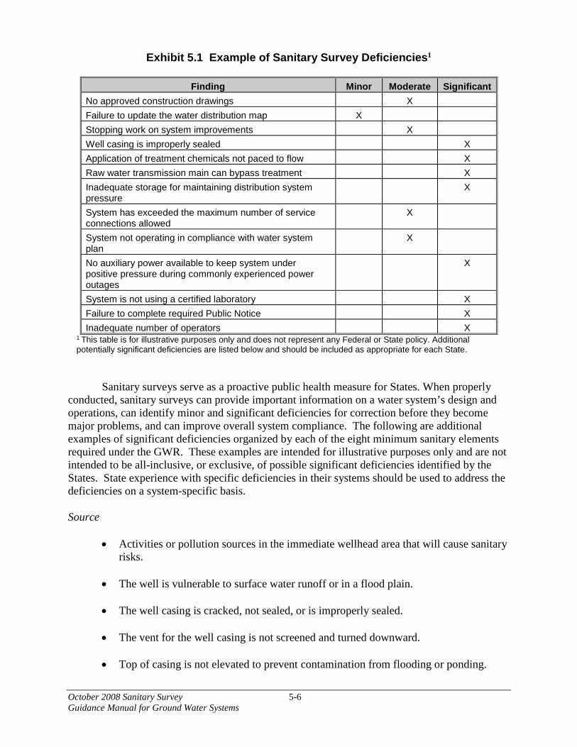
October 2008 Sanitary Survey 5-6Guidance Manual for Ground Water Systems
Exhibit 5.1 Example of Sanitary Survey Deficiencies1
Finding Minor Moderate Significant No approved construction drawings X Failure to update the water distribution map X Stopping work on system improvements X Well casing is improperly sealed X Application of treatment chemicals not paced to flow X Raw water transmission main can bypass treatment X Inadequate storage for maintaining distribution system pressure
X
System has exceeded the maximum number of service connections allowed
X
System not operating in compliance with water system plan
X
No auxiliary power available to keep system under positive pressure during commonly experienced power outages
X
System is not using a certified laboratory X Failure to complete required Public Notice X Inadequate number of operators X
1 This table is for illustrative purposes only and does not represent any Federal or State policy. Additional potentially significant deficiencies are listed below and should be included as appropriate for each State.
Sanitary surveys serve as a proactive public health measure for States. When properly conducted, sanitary surveys can provide important information on a water system’s design and operations, can identify minor and significant deficiencies for correction before they become major problems, and can improve overall system compliance. The following are additional examples of significant deficiencies organized by each of the eight minimum sanitary elements required under the GWR. These examples are intended for illustrative purposes only and are not intended to be all-inclusive, or exclusive, of possible significant deficiencies identified by the States. State experience with specific deficiencies in their systems should be used to address the deficiencies on a system-specific basis.
Source
• Activities or pollution sources in the immediate wellhead area that will cause sanitaryrisks.
• The well is vulnerable to surface water runoff or in a flood plain.
• The well casing is cracked, not sealed, or is improperly sealed.
• The vent for the well casing is not screened and turned downward.
• Top of casing is not elevated to prevent contamination from flooding or ponding.
October 2008 Sanitary Survey 5-7 Guidance Manual for Ground Water Systems
• Well is not secure and is susceptible to vandalism and tampering.
• Cross connections exist to storm drains, sanitary sewers, non potable water supplies, or a pump bearing cooling water.
• Unapproved source is being used.
• Non- microbial indicators of well susceptibility to fecal contamination are present (e.g., methylene blue active substances [MBAS], high chloride or nitrate levels from baseline or historic trends).
Treatment
• System is not in compliance with applicable treatment technique requirements.
• Inadequate disinfection contact time, disinfectant concentration, disinfectant dose, or disinfection is not continuous.
• Inadequate application of treatment chemicals, not paced to flow.
• Unapproved treatment chemicals used.
• Lack of treatment process monitoring, failure alarms, or automatic process shutdown.
• Cross connections at chemical tanks, filter backwash, membrane cleaning processes.
• Loss of membrane integrity or lack of monitoring of membrane integrity.
• Auxiliary power is not available, power outages can cause a complete shutdown of treatment.
• Lack of redundant components.
• Failure to act in an emergency situation. Distribution and Transmission
• Customers are receiving raw water from the raw water transmission main (where treatment is required).
• The raw water transmission main is equipped with a bypass around the treatment plant.
• Repeated or frequent TCR violations or detections of fecal indicators.
• The TCR sampling plan is not representative of the distribution system.
October 2008 Sanitary Survey 5-8 Guidance Manual for Ground Water Systems
• The system receives numerous complaints of colored and/or odorous water.
• Required disinfection residual levels are not met.
• Compliance monitoring is not conducted at the required frequency and locations.
• Pressures in parts of the distribution system fall below 20 psi during periods of high demand.
• The system is subject to contamination from hazardous cross connections.
• Failure to have a cross connection control program when one is required.
• High leakage rates that pose risks of backsiphonage.
• Inadequate separation between distribution system mains and sewer lines. Finished water storage
• Inadequate storage to maintain adequate distribution system pressure.
• The tank’s vents or overflows are not screened or protected.
• Tank’s overflows or drains are subject to flooding.
• Holes or other failures of tank roof or structure, faulty roof, or faulty floating cover drainage.
• In ground tanks subject to flooding.
• The entry hatch tank is not of the overlapping shoe-box type and is subject to runoff from the tank roof.
• Ladder protection is missing or loose.
• The tank’s entry hatch or access ladders are not secured.
• The storage tank has not been surveyed for sanitary defects for an extended period of time.
Pumps, pump facilities, and controls
• Unapproved oil is used for pump lubrication.
• The air/water relief valves provide a cross connection to the floor drains.
October 2008 Sanitary Survey 5-9 Guidance Manual for Ground Water Systems
• Auxiliary power needed to keep the system under positive pressure during commonly experienced power outages is not available.
• There is a lack of redundant pumps.
• Cross connections to non-potable supplies, pump or generator cooling water lines. Monitoring, reporting, and data verification
• The system has been found to be in significant non-compliance for one or more contaminants.
• Operators are using improper procedures and/or methods when conducting onsite laboratory analyses.
• The system does not have a compliance or microbial monitoring plan.
• The system is not using a certified laboratory.
• Failure to complete Operational Evaluation Reports. System management and operation
• System security is inadequate.
• Failure to complete required Public Notice.
• Failure to notify the State of MCL violations or ground water source fecal contamination.
• Variance or exemption conditions or schedules not met. • Failure to comply with enforcement actions and compliance agreements. • System does not have adequate Technical, Managerial or Financial capacity, or
revenue to ensure continued operation. Operator compliance with State requirements
• The operator is not certified at the level/grade required by the State.
• Inadequate number of operators.
5.4 Corrective Action If the State determines that a significant deficiency exists in a system subject to the GWR, corrective action is required. To ensure that the sanitary risks are minimized, the sanitary
October 2008 Sanitary Survey 5-10 Guidance Manual for Ground Water Systems
survey report or notice of significant deficiency should provide the water utility with options or recommendations for correcting significant defects if the State does not specify corrective actions. The GWR requires that those systems notified in writing by the State of significant deficiencies implement corrective action, including one or more of the following:
• Eliminate the source of contamination,
• Correct the deficiency,
• Provide an alternative water source, or
• Provide treatment that reliably achieves at least 4-log (99.99%) treatment of viruses before or at the first customer.
Once a system has received written notification of a significant deficiency, the system will then consult with the State regarding corrective action (if the State does not specify corrective action) within 30 days of the notice. The system must take the appropriate corrective action no later than 120 days (or earlier if directed by the State) after notification, or be in compliance with a State-approved plan for correcting these deficiencies at the end of the same 120 day period. The States must then confirm that the deficiencies have been addressed within 30 days after the scheduled correction of the deficiencies. Upon receiving the sanitary survey report or other notice of significant deficiency from the State, PWSs should carefully plan the corrective measures that are to be adopted and implemented to correct the identified significant deficiencies. There may be a number of adequate corrective actions or combination of actions that may be applied to a significant deficiency. The system and the State, must, before proceeding, know that the planned corrective actions will eliminate the deficiency without creating new sanitary risks or other compliance problems. For example, if a system replaced a substandard well that was determined by the State to have a significant deficiency without obtaining the State’s review and approval, the action could result in another substandard well and a finding of noncompliance with the State’s construction and permitting standards. This example and many others often require modifications that, in many States, must be subsequently reviewed and approved by the State. Therefore, in all cases the PWS should seek the advice and approval of their primacy agency prior to taking corrective action. 5.5 Outstanding Performance As noted in Chapter 1, community systems that are classified as having outstanding performance are eligible for having future sanitary surveys conducted at the less frequent interval of at least once every five years, rather than at least once every three years. Based on the findings of a sanitary survey, a surveyor should include in the report a recommendation on whether a system should be considered to have outstanding performance at the time of the survey. This recommendation should be based on the State’s specifications for determining if a system has outstanding performance. Along with the surveyor’s recommendation, the report

October 2008 Sanitary Survey 5-11 Guidance Manual for Ground Water Systems
should include standard State language (“boilerplate”) noting that the recommendation for outstanding performance status is contingent upon the system continuing to meet the State’s specifications for that status. In general, outstanding performance means that a system is well-operated and managed, has a good record of performance in past sanitary surveys, and has not had any violations (at least in recent years). A State’s specifications for outstanding performance may include factors such as the following:
• No violations of MCLs since the last sanitary survey;
• No violations of monitoring and reporting requirements since the last sanitary survey;
• No violations of primary drinking water regulations during the past five years (or similar time period);
• Past sanitary surveys containing no significant deficiencies;
• Existence of emergency preparedness measures and backup facilities;
• Meeting exceptional performance standards a specified high percentage of the time;
• Expert management of system (e.g., managers are knowledgeable about providing quality drinking water; low staff turnover; well-established water quality goals);
• Expert operation of the system (e.g., skilled, certified personnel in adequate numbers; existence of quality O&M manuals that are used by the staff; adequate budget and revenues);
• Effective cross-connection program developed and implemented;
• In-house programs applicable to improved system performance;
• Active public outreach programs (e.g., citizen participation committees);
• Stable water source (no interruptions in supply);
• No identified significant risk of future violations or problems (e.g., equipment past its service life);
• System capacity sufficient to meet anticipated growth; and
• Asset management program and Capital Improvement Plan. As noted above, each State should have its own specifications for determining if a system has outstanding performance. The State may choose to use some or all of the above factors, different factors that have been developed by the State, or a combination of both.

October 2008 Sanitary Survey 6-1 Guidance Manual for Ground Water Systems
6. Report Review and Response The previous chapters of this guidance manual described how to prepare, conduct, and report the results of a sanitary survey. This chapter describes the follow-up actions that should be taken by the water system operator and the State in response to the findings of a sanitary survey, including those actions that must be taken to correct any identified significant deficiencies. The State then needs to monitor the water system’s implementation of corrective actions to ensure that significant deficiencies are resolved. The remainder of this chapter discusses these follow-up actions. 6.1 State Actions For a State to be granted primacy authority for the GWR, it must submit information to EPA that the State has met the requirements for a determination of primacy enforcement responsibility found in 40 CFR 142.16. The special primacy requirements related to sanitary surveys are summarized in Exhibit 6.1. In addition to meeting minimum scope and frequency for sanitary surveys, States must have the authority to ensure that ground water systems address significant deficiencies. The GWR requires that the State notify systems of findings of significant deficiencies no later than 30 days after the significant deficiency is identified. Unless the State directs corrective action or earlier compliance, the system must consult with the State within 30 days and take corrective action, or be in compliance with a State-approved schedule, within 120 days of being notified of the significant deficiency. States are required to confirm that the significant deficiencies have been addressed within 30 days of being notified by the system of the correction of the deficiencies. Deficiencies of a minor nature may require no more response than to notify the system of the deficiency and set a time frame for the operator to correct the situation. For significant deficiencies, the State should inform the system of the deficiency as soon as possible. Under the GWR, the State may inform the system in writing at the time of the sanitary survey or identification of the significant deficiency. In severe cases, the significant deficiency may be such that a boil water notice should be issued to the customers in order to protect public health. In other cases, other immediate interim measures to protect public health may be needed. Under the GWR, the State may specify interim corrective measures during the 120 day period the system is completing final corrections or completing its corrective action plan and schedule. The State should inform the system of the time frame required for a response to the notice of significant deficiencies and the consequences of failing to respond. In addition to a potential for violation of the GWR and associated enforcement action, the consequences could include revocation of the operating permit, suspension of the permit until the deficiency is corrected, and fines or penalties levied against the system. When significant deficiencies require an extended period for correction, a consent agreement, administrative order, or litigation by the appropriate court may be necessary to ensure correction. The State should make regular and continued surveys of the facility until all significant deficiencies have been corrected. Other State activities include maintaining a tracking system for enforcement. The 1995 EPA/State Joint Guidance on Sanitary Surveys states that the deficiencies disclosed in a survey
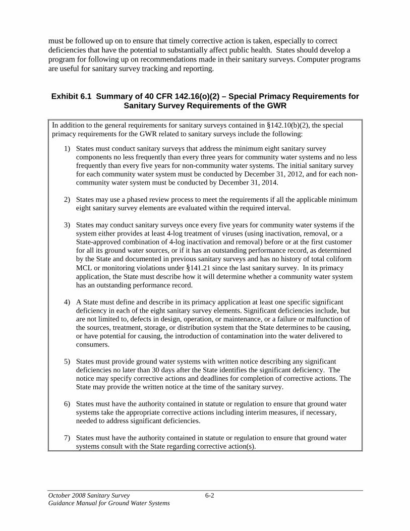
October 2008 Sanitary Survey 6-2 Guidance Manual for Ground Water Systems
must be followed up on to ensure that timely corrective action is taken, especially to correct deficiencies that have the potential to substantially affect public health. States should develop a program for following up on recommendations made in their sanitary surveys. Computer programs are useful for sanitary survey tracking and reporting. Exhibit 6.1 Summary of 40 CFR 142.16(o)(2) – Special Primacy Requirements for
Sanitary Survey Requirements of the GWR In addition to the general requirements for sanitary surveys contained in §142.10(b)(2), the special primacy requirements for the GWR related to sanitary surveys include the following:
1) States must conduct sanitary surveys that address the minimum eight sanitary survey components no less frequently than every three years for community water systems and no less frequently than every five years for non-community water systems. The initial sanitary survey for each community water system must be conducted by December 31, 2012, and for each non-community water system must be conducted by December 31, 2014.
2) States may use a phased review process to meet the requirements if all the applicable minimum eight sanitary survey elements are evaluated within the required interval.
3) States may conduct sanitary surveys once every five years for community water systems if the system either provides at least 4-log treatment of viruses (using inactivation, removal, or a State-approved combination of 4-log inactivation and removal) before or at the first customer for all its ground water sources, or if it has an outstanding performance record, as determined by the State and documented in previous sanitary surveys and has no history of total coliform MCL or monitoring violations under §141.21 since the last sanitary survey. In its primacy application, the State must describe how it will determine whether a community water system has an outstanding performance record.
4) A State must define and describe in its primacy application at least one specific significant deficiency in each of the eight sanitary survey elements. Significant deficiencies include, but are not limited to, defects in design, operation, or maintenance, or a failure or malfunction of the sources, treatment, storage, or distribution system that the State determines to be causing, or have potential for causing, the introduction of contamination into the water delivered to consumers.
5) States must provide ground water systems with written notice describing any significant deficiencies no later than 30 days after the State identifies the significant deficiency. The notice may specify corrective actions and deadlines for completion of corrective actions. The State may provide the written notice at the time of the sanitary survey.
6) States must have the authority contained in statute or regulation to ensure that ground water systems take the appropriate corrective actions including interim measures, if necessary, needed to address significant deficiencies.
7) States must have the authority contained in statute or regulation to ensure that ground water systems consult with the State regarding corrective action(s).
October 2008 Sanitary Survey 6-3 Guidance Manual for Ground Water Systems
6.2 Water System Actions As stated previously, the severity of the deficiency in a sanitary survey should dictate the appropriate response from the water system. The system, upon receipt of the sanitary survey report or other notice of significant deficiency, should prepare a response to address the survey findings that may include deficiencies of varying degrees of severity. The response should include:
• A statement of the deficiency; • The approach to correcting the deficiency;
• The time required to correct the deficiency;
• The source of funding, if capital construction is required;
• Measures put in place to prevent the situation from recurring; and
• Additional follow-up actions planned.
The GWR does not change the requirement for a water system to maintain copies of sanitary survey written reports and correspondence associated with sanitary surveys for a period of at least 10 years, as specified in 40 CFR 141.33(c). In addition to this requirement, the water system should follow any applicable State implementing regulations related to sanitary survey record keeping. The GWR also requires CWSs to notify the public of any detections of fecal indicators in their ground water source(s) or of any uncorrected significant deficiencies in the system’s Consumer Confidence Report. Non-community water systems must notify the public of any significant deficiencies that are not corrected within 12 months in a manner approved by the State. PWSs should refer to EPA’s Revised Public Notification Handbook (EPA 816-R-07-003) and the Public Notification Handbook for Transient Non-Community Water Systems (EPA 816-R-07-004) for guidance on preparing and distributing public notices. Notice of uncorrected significant deficiencies must continue annually for both CWSs and NCWSs until the significant deficiencies have been corrected.


October 2008 Sanitary Survey A-1 Guidance Manual for Ground Water Systems
Appendix A Evaluating Ground Water Treatment for Ground Water Rule Compliance
A.1 Introduction
This appendix provides information to assist States in evaluating ground water treatment for systems that provide and monitor ground water treatment and do not conduct GWR triggered monitoring after a TCR-positive or for systems that use ground water treatment as a corrective action.
Under the GWR, ground water systems that provide at least 4-log (99.99%) treatment of viruses (through inactivation, removal, or a State-approved combination of inactivation and removal), and also meet the compliance monitoring requirements of the GWR, are not required to conduct triggered source water monitoring after a routine TCR-positive sample. States may also approve or require 4-log treatment of viruses as a corrective action for fecal contamination of ground water sources or as a corrective action for significant deficiencies.
To meet the requirements of the GWR, 4-log treatment of viruses may be accomplished through inactivation (i.e., disinfection), removal (i.e., filtration) or a State-approved combination of inactivation and removal. This appendix describes common inactivation and filtration technologies and their applicability to GWR treatment technique requirements. This appendix is not intended to be inclusive, or exclusive, of all possible treatment technologies, or combinations of technologies, to meet the GWR treatment technique requirements. States may approve alternative treatment technologies, or combinations of technologies, that provide 4-log treatment of viruses to meet the GWR treatment technique requirements. A.2 Inactivation of viruses
Inactivation of viruses is accomplished with sufficient disinfectant concentration and disinfectant contact time for chemical disinfectants or sufficient dose for inactivation with ultraviolet light (UV). Chemical disinfectants capable of providing 4-log treatment of viruses as a stand-alone treatment include chlorine, chlorine dioxide, chloramine and ozone. Chemical disinfection and UV inactivation are discussed separately below. A.2.1 Chemical disinfection
Inactivation of pathogens, including viruses, using a chemical disinfectant is based on the CT concept where C is the measured concentration of the chemical disinfectant residual and T is the contact time between the point of application of the disinfectant and the point where the disinfectant residual is measured.
C, the concentration of the disinfectant, is measured at or before the first customer
receiving water or the first connection providing water to the public from the system. For a system using chlorine or chloramine, the residual concentration can be measured with a portable kit or with a continuous monitor using an EPA approved measurement method. A list of EPA

October 2008 Sanitary Survey A-2 Guidance Manual for Ground Water Systems
approved methods can be found on-line at http://www.epa.gov/waterdata or at https://www.epa.gov/learn-issues/learn-about-water. Your State may have a list of approved measurement methods as well. T, the contact time of the disinfectant, is based on system flow and components. Determining flow and T are discussed later in this section.
Once C is measured and T is determined from the flow and the size of the system
components, the product, C x T (CT), is compared to EPA or State information of the CT needed for the inactivation, through disinfection, of a pathogen. EPA has produced tables of CT values and your State may have information it uses for this purpose. Exhibits A.1, A.2, and A.3, respectively, are CT tables for inactivation of viruses by chlorine, chlorine dioxide and ozone respectively. CT tables for chloramine are not included here because the CT values required for a 4-log inactivation of viruses are not likely to be practical for applications in most ground water systems. CT values for inactivation of viruses by chloramine can be found in the Guidance Manual for Compliance with the Filtration and Disinfection Requirements for Public Water Systems Using Surface Water Sources (USEPA, 1990) and could be used for ground water systems using chloramines.
For the GWR, if a chemical disinfection system can achieve a CT at least equal to the CT
needed for a 4-log inactivation of viruses for the disinfectant being used, the system is not required to meet the triggered monitoring requirements of the rule. However, such a system would have to comply with the treatment and compliance monitoring requirements of the GWR and any additional requirements set by the State. If approved or required by the State, such a system would also meet the corrective action requirements of the GWR for fecally contaminated ground water source or for significant deficiencies. The special primacy requirements of the GWR require State to specify a minimum disinfectant residual, to be met at or prior to the first customer, for system using disinfection to meet the treatment technique requirements of the rule. The CT concept would be used to set this minimum disinfectant residual.
The following minimum information is needed to determine if a chemical disinfection
system is providing a 4-log virus inactivation for the purposes of the GWR: 1. C, the measured disinfectant residual at or before the first customer or connection
serving the public. It is measured in mg/l or in ppm.
2. Length (in feet) of each pipe between the point where disinfectant is applied and the point where it is measured.
3. Size (diameter) of each pipe between the point where disinfectant is applied and the point where it is measured. The diameter in inches must be converted to diameter in feet (1 inch=1/12 foot).
4. Volume of water (in gallons) in any storage tanks used to determine CT provided by the system.
5. Maximum flow, in gallons per minute (gpm), of the system. This could be as measured by a flow meter, the maximum capacity of the well pump, or another measurement acceptable to the State.
6. The pH and temperature of the water supply.

October 2008 Sanitary Survey A-3Guidance Manual for Ground Water Systems
The following example illustrates how this information is used to calculate CT and to determine if a chemical disinfection system is providing a 4-log inactivation of viruses.
Example A.1
The Redwood Road water system serves 4 commercial businesses and a service station. The water supply is provided by a single well on the property that is operated by a pressure activated switch. The information supplied with the well pump that was purchased for the system says it has a capacity of 5 gpm. A hypochlorite solution is injected using a drum of prepared solution and an injection pump inside the well house. The operator wants to determine how much virus inactivation the disinfection system provides.
To determine the inactivation the system provides through disinfection, the operator needs to calculate the CT achieved by the hypochlorination system.
• The operator must determine T, the contact time, from the volume of water held inthe system’s components and the maximum daily flow, and the operator mustmeasure C, the disinfectant residual concentration, at or before the first serviceconnection.
• The operator knows the well pump has a capacity of 5 gallons per minute (gpm) fromthe manufacturer’s information. This is the maximum flow through the water system.T, the contact time in the system is the volume (in gallons) of the system divided bythe maximum flow.
• The operator knows there are 100 feet of 2 inch pipe between the well house and thefirst service connection, the service station. The volume of the pipe in cubic feet andthen in gallons is determined. The volume of the pipe in gallons is divided by theflow to find the contact time.
The operator measures the chlorine residual at the service station and finds it to be 0.5 mg/l. So, the CT provided by the system is 0.5 mg/ l × 3.3 minutes = 1.6 mg/l-minutes
The diameter of the pipe is 2 inches or 2/12 feet. The area of the pipe is [π × (diameter2)]÷4 and π=3.14,or the area is also 0.785× diameter2
So the area of the pipe is 0.785 × (2/12 feet)2 =0.022 sq.ft. The volume of the pipe in cubic feet=100 feet × (0.022 sq. ft.)=2.2 cubic feet The volume of the pipe in gallons is 2.2 cubic feet × 7.48 gallons/cubic foot=16.4 gallons
The contact time, T, in the pipe is the volume of the pipe divided by the flow T= 16.4 gallons ÷ 5 gpm=3.3 minutes
October 2008 Sanitary Survey A-4 Guidance Manual for Ground Water Systems
The CT needed for 4-log inactivation of viruses using chlorine is provided in Exhibit A.1. The operator has measured the temperature of the water as 10oC and the last chemical analysis done for the well found a pH of 7.4 for the well water. Looking in Exhibit A.1 the CT needed for that temperature and pH for a 4-log inactivation with chlorine disinfection is 6 mg/l-minutes.
To provide 4-log inactivation, the CT provided by the system must be equal to or greater than the CT required from Table 1 (or the ratio of CT required/CT achieved must be 1.0 or more). Since the CT provided by the system, 1.6 mg/l-minutes, is less that the CT required from Table 1 (6 mg/l-minutes), the system does not provide enough CT to achieve 4-log inactivation of viruses. If the system was required to provide 4-log inactivation or wished to provide it to avoid triggered monitoring, the CT provided by the system would need to be greater.
A.2.2 Determining Contact Time, “T”, for CT calculations
In determining contact time for flow in pipes, as in the previous example, contact time can be assumed to be equal to the hydraulic detention time at a particular flow rate (e.g., plug flow conditions). However, that is not the case for storage tanks and reservoirs and treatment plant processes. In these cases, contact time should be determined using tracer studies or using other methods approved by the State.
Appendix C of the Guidance Manual for Compliance with the Filtration and Disinfection Requirements for Public Water Systems Using Surface Water Sources (USEPA, 1990) provides a description of tracer studies and tracer study methods. In general, tracer studies should represent the range of flow and operational conditions expected in the system and should have data quality criteria (i.e., percent tracer recovered). Tracer chemicals used should be conservative (high percent recovery) and should be acceptable to the State for use in public water supplies.
Ground water systems may not have tracer study data available and conducting tracer studies may be beyond the capacity of many ground water systems. States may use other methods to determine contact time for use in CT calculations and determining minimum disinfectant residual for GWR compliance purposes.
One alternate method is to use “rule of thumb” fractions representing tracer studies that have been conducted for various types and geometries of various basins and storage facilities. Exhibit A.4 presents fractions that can be used under a given set of conditions to estimate contact time for CT calculation. For a particular tank or process, the baffling factor (also known as the T10/T ratio) is estimated based on the information available or a conservative assumption is made if no information regarding the tank is available. The baffling factor is used to reduce the contact time in the basin for CT calculations. Operating conditions in the basin (i.e., overflow levels) also need to be considered in determining actual basin volume. Example A.2 presents the use of baffling factors in determining contact time in a storage tank. A conservative approach to determining minimum contact time and setting minimum disinfectant residual is to use a baffling factor of 0.1. It is important to note that, under certain hydraulic or flow conditions, flow may bypass tanks and storage facilities with a common inlet and outlet and there may be no disinfectant contact time provided. Due to their operating characteristics, pressure bladders and hydropneumatic tanks may not provide continuous disinfectant contact time.

October 2008 Sanitary Survey A-5Guidance Manual for Ground Water Systems
Example A.2
The operator of the Myrtletown water system wants to estimate the contact time in the system’s single storage tank. The operator has calculated that the minimum capacity of the tank is 11,000 gallons based on the level of the float switch that signals the well pump to turn on and off. The operator has records from the flow meter at the tank outlet and the maximum flow over the past 12 months was 55 gallons per minute.
The storage tank has a single baffle in front of the inlet pipe and the inlet and outlet are located on opposite sides of the tank. The operator chooses a baffling factor of 0.1.
The theoretical hydraulic detention time in the tank is 11,000 gallons÷55gallons/minute or 200 minutes. Using the baffling factor of 0.1, the estimated contact time in the tank under maximum flow conditions is 0.1×200 minutes which equals 20 minutes.
To determine the virus inactivation provided by the Myrtletown system, the estimated contact time is multiplied by the disinfectant residual measured at or before the first customer to find the “CT” provided. If the Myrtletown system used chemical disinfection for compliance with the GWR (either as a corrective action or in lieu of triggered monitoring), the system would be required to provide a minimum residual level determined by the State using the CT approach.
A.2.3 Setting a Minimum Disinfectant Residual
The GWR requires that the State specify a minimum disinfectant residual, to be met at or prior to the first customer, for systems using chemical disinfection to provide virus treatment for their ground water sources. The minimum disinfectant residual is established using the CT concept. In setting a minimum disinfectant level, which becomes a compliance criterion for the system, the following information should be reviewed and considered:
• System configuration and operations (e.g., location of first customer, operation ofstorage, bypass of storage);
• The range of operating conditions (e.g., continuous or intermittent, peak flows);
• The range of expected water quality affecting disinfection (e.g., temperature, pH,disinfectant demand);
• Residual monitoring equipment (e.g., grab sample/portable kit, continuousmonitoring);
• Condition of monitoring equipment, reagents and other supplies, maintenance andcalibration of continuous monitoring equipment; and
• Disinfection system reliability features (e.g., alarms, automatic shutdown).

October 2008 Sanitary Survey A-6 Guidance Manual for Ground Water Systems
A.2.4 UV Disinfection EPA has identified UV doses for virus inactivation credit, which are shown in Exhibit A.5. These doses are based on the inactivation of adenoviruses, which are particularly resistant to UV light. EPA is concerned that fecally-contaminated ground water may contain adenoviruses and/or other UV resistant viruses that present a human health risk. The UV doses in Exhibit A.5 are significantly higher than those considered for the proposed GWR (USEPA, 2000). When developing the proposed rule, EPA considered only the UV inactivation of Hepatitis A virus (HAV), which is much less resistant to UV light than adenovirus. Based on HAV inactivation alone, EPA included UV light in the GWR proposal regulatory text as a stand-alone treatment technology that could provide 4-log virus inactivation. However, data published subsequent to the GWR proposal indicated that some viruses, particularly adenoviruses, are much more resistant to UV light than HAV. The Agency believes that the UV doses in Exhibit A.5 are sufficient to achieve the designated level of inactivation of all waterborne pathogenic viruses that have been studied. UV reactors should undergo validation testing to determine the operating conditions under which the reactor delivers the UV dose required for the necessary virus inactivation level. In general, the operating conditions determined in validation testing should include flow rate, UV intensity as measured by a UV sensor, and UV lamp status. These operating conditions, as well as any State-specified monitoring or operating conditions, would be both a part of State approval of an alternative treatment process that meet the requirement of the GWR and part of compliance monitoring for an alternative treatment process for GWR compliance. The Ultraviolet Disinfection Guidance Manual for the Final Long Term 2 Enhanced Surface Water Treatment Rule (EPA 815-R-06-007) (USEPA, 2006a) provides additional information on UV disinfection, planning and design of UV facilities, validation of UV reactors, and start-up and operation of UV facilities. At present, EPA is unaware of available testing protocols that can validate the performance of UV reactors at the dose of 186 mJ/cm2 needed for a 4-log virus inactivation credit. However, UV reactors validated at lower doses can be used in a series configuration or in combination with other inactivation or removal technologies to provide a total 4-log treatment of viruses to meet GWR requirements. The GWR allows States to approve and set compliance monitoring and performance parameters for any alternative treatment, including UV light or UV light in combination with another treatment technology, which will ensure that systems continuously meet the 4-log virus treatment requirements. Further, a UV reactor validation protocol for 4-log inactivation of viruses may be developed in the future. The UV dose requirements shown in Exhibit A.5 were derived exclusively from studies with low pressure (LP) UV lamps. UV dose is well defined and can be determined accurately for this type of lamp. However, a recent bench scale study has observed that medium pressure (MP) and pulsed UV (PUV) lamps may inactivate viruses, particularly adenovirus, at lower UV doses than LP UV lamps (Linden et al., 2007). A recent full scale study also found that MP UV lamps may inactivate adenovirus at lower doses than LP UV lamps (Linden et al., 2008). MP and PUV lamps emit UV light at many wavelengths (polychromatic), while LP UV lamps primarily emit light at a single wavelength.
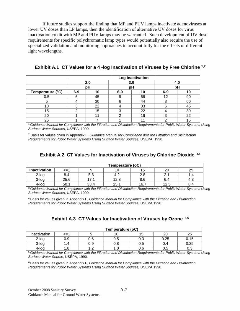
October 2008 Sanitary Survey A-7 Guidance Manual for Ground Water Systems
If future studies support the finding that MP and PUV lamps inactivate adenoviruses at lower UV doses than LP lamps, then the identification of alternative UV doses for virus inactivation credit with MP and PUV lamps may be warranted. Such development of UV dose requirements for specific polychromatic lamp types would potentially also require the use of specialized validation and monitoring approaches to account fully for the effects of different light wavelengths.
Exhibit A.1 CT Values for a 4 -log Inactivation of Viruses by Free Chlorine 1,2
Log Inactivation 2.0 3.0 4.0 pH pH pH
Temperature (oC) 6-9 10 6-9 10 6-9 10 0.5 6 45 9 66 12 90 5 4 30 6 44 8 60
10 3 22 4 33 6 45 15 2 15 3 22 4 30 20 1 11 2 16 3 22 25 1 7 1 11 2 15
1 Guidance Manual for Compliance with the Filtration and Disinfection Requirements for Public Water Systems Using Surface Water Sources, USEPA, 1990. 2 Basis for values given in Appendix F, Guidance Manual for Compliance with the Filtration and Disinfection Requirements for Public Water Systems Using Surface Water Sources, USEPA, 1990.
Exhibit A.2 CT Values for Inactivation of Viruses by Chlorine Dioxide 3,4
Temperature (oC) Inactivation <=1 5 10 15 20 25
2-log 8.4 5.6 4.2 2.8 2.1 1.4 3-log 25.6 17.1 12.8 8.6 6.4 4.3 4-log 50.1 33.4 25.1 16.7 12.5 8.4
3 Guidance Manual for Compliance with the Filtration and Disinfection Requirements for Public Water Systems Using Surface Water Sources, USEPA, 1990. 4 Basis for values given in Appendix F, Guidance Manual for Compliance with the Filtration and Disinfection Requirements for Public Water Systems Using Surface Water Sources, USEPA,1990.
Exhibit A.3 CT Values for Inactivation of Viruses by Ozone 5,6
Temperature (oC) Inactivation <=1 5 10 15 20 25
2-log 0.9 0.6 0.5 0.3 0.25 0.15 3-log 1.4 0.9 0.8 0.5 0.4 0.25 4-log 1.8 1.2 1.0 0.6 0.5 0.3
5 Guidance Manual for Compliance with the Filtration and Disinfection Requirements for Public Water Systems Using Surface Water Source, USEPA, 1990. 6 Basis for values given in Appendix F, Guidance Manual for Compliance with the Filtration and Disinfection Requirements for Public Water Systems Using Surface Water Sources, USEPA 1990.
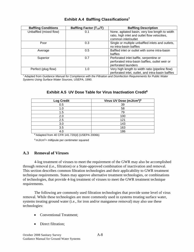
October 2008 Sanitary Survey A-8 Guidance Manual for Ground Water Systems
Exhibit A.4 Baffling Classifications7
Baffling Conditions Baffling Factor (T10/T) Baffling Description Unbaffled (mixed flow) 0.1 None, agitated basin, very low length to width
ratio, high inlet and outlet flow velocities, common inlet/outlet
Poor 0.3 Single or multiple unbaffled inlets and outlets, no intra-basin baffles
Average 0.5 Baffled inlet or outlet with some intra-basin baffles
Superior 0.7 Perforated inlet baffle, serpentine or perforated intra-basin baffles, outlet weir or perforated launders
Perfect (plug flow) 1.0 Very high length to width ratio (pipeline flow) perforated inlet, outlet, and intra-basin baffles
7 Adapted from Guidance Manual for Compliance with the Filtration and Disinfection Requirements for Public Water Systems Using Surface Water Sources, USEPA, 1990.
Exhibit A.5 UV Dose Table for Virus Inactivation Credit8
Log Credit Virus UV Dose (mJ/cm2)9 0.5 39 1.0 58 1.5 79 2.0 100 2.5 121 3.0 143 3.5 163 4.0 186
8 Adapted from 40 CFR 141.720(d) (USEPA 2006b) 9 mJ/cm2= millijoule per centimeter squared
A.3 Removal of Viruses
4-log treatment of viruses to meet the requirement of the GWR may also be accomplished through removal (i.e., filtration) or a State-approved combination of inactivation and removal. This section describes common filtration technologies and their applicability to GWR treatment technique requirements. States may approve alternative treatment technologies, or combinations of technologies, that provide 4-log treatment of viruses to meet the GWR treatment technique requirements. The following are commonly used filtration technologies that provide some level of virus removal. While these technologies are more commonly used in systems treating surface water, systems treating ground water (i.e., for iron and/or manganese removal) may also use these technologies:
• Conventional Treatment;
• Direct filtration;

October 2008 Sanitary Survey A-9 Guidance Manual for Ground Water Systems
• Slow sand filtration; and
• Diatomaceous Earth Filtration.
When properly designed and operated, these technologies are capable of achieving at least 1-log removal of viruses (USEPA, 1990) Membrane filtration technologies provide some level of virus removal and the GWR includes specific requirements for the use of membrane filters. States may also approve alternative filtration technologies if those technologies can demonstrate removal of viruses and can be monitored to show continuing removal efficacy. A.3.1 Membrane Technologies Under the GWR, membrane technologies used to provide 4-log removal of viruses to meet GWR requirements must have an absolute molecular weight cut off (MWCO), or an alternate parameter that describes the exclusion characteristics of the membrane, that reliably achieves at least 4-log removal of viruses. Generally, only ultrafiltration, nanofiltration, and reverse osmosis membranes provide virus removal. While microfiltration has been shown to achieve partial virus removal in some cases, removal is typically attributable to the formation of a time-dependant cake layer on the membrane surface, thus microfiltration is generally considered to be unreliable for high levels of virus removal, such as those required by the GWR (USEPA, 2005). Manufacturers of membrane technologies may have performed challenge or demonstration studies according to State or other protocols to demonstrate virus removal performance. Manufacturers may have also participated in treatment device certification programs such as the National Sanitation Foundation (NSF) (http://www.nsf.org) or EPA’s Environmental Technology Verification (ETV) Program (https://www3.epa.gov/ttn/amtic/etvinfo.html). The GWR also requires that membrane technologies used to provide 4-log removal of viruses to meet GWR requirement be operated in accordance with State-specified performance requirements and show that the integrity of the membrane is intact. The most accurate method of demonstrating membrane integrity currently available is direct integrity testing. The most commonly applied direct integrity test is the pressure decay test, but other tests such as the vacuum decay test are used in some applications. Three important attributes of a direct integrity test are defined in the Membrane Filtration Guidance Manual (USEPA, 2005): sensitivity, resolution, and frequency. Available direct integrity tests are capable of demonstrating integrity capable of achieving 4-log removal, however site-specific conditions may result in direct integrity test sensitivity lower than 4-log removal. Thus it is important to demonstrate the sensitivity of a direct integrity test in each application of the technology. States may choose to limit the virus removal credit awarded to a membrane process based on the demonstrated sensitivity of the direct integrity test. Resolution is the smallest integrity breach that contributes to the response from a direct integrity test. EPA is not aware of any commonly used, pressure-based direct integrity test that can achieve a resolution consistent with the size of a virus particle. The required test pressure is

October 2008 Sanitary Survey A-10 Guidance Manual for Ground Water Systems
beyond the pressure tolerances of most membrane technologies in use today and pressure-based direct integrity test applied at lower pressures may not detect small integrity breaches that could pass viruses and thus compromise the log-removal capability of the system. Appendix E of the Membrane Filtration Guidance Manual (USEPA, 2005) provides additional information on the application of direct integrity tests to membrane processes used for virus removal. Continuous indirect integrity monitoring, using turbidity, particle counts or other surrogate water quality parameters, may be used to assess membrane integrity on a continuous basis and establish performance criteria. Some methods of indirect integrity monitoring may not have sufficient accuracy to serve as more than gross measures of membrane integrity for virus removal (USEPA, 2005). For most ground water sources, turbidity and particles are not likely to be present at levels high enough to set performance criteria or use in continuous monitoring and States may need to use other water quality parameters (e.g., TDS, conductivity) or operating parameters (e.g., transmembrane pressure, flux rate) as performance indicators. Monitoring of some parameters may require laboratory analysis or additional monitoring equipment. It is important to note that the continuous indirect integrity monitoring techniques discussed here are significantly less sensitive than direct integrity tests, and do not provide verification that membrane integrity is sufficient to meet virus log removal requirements. Rather, continuous indirect integrity monitoring is used to monitor for major integrity problems, such as a failed seal or end-cap. As with other treatment technologies, membranes may be combined with another treatment technology to provide a total of 4-log treatment of viruses. The combination of a membrane technology with chlorine disinfection, which easily inactivates viruses at low doses, would provide multiple virus barriers with a level of redundancy. A.3.2 Alternative Filtration Technologies As with membrane technologies, manufacturers of alternative filtration technologies may have performed challenge or demonstration studies according to State or other protocols to demonstrate virus removal performance. Manufacturers may have also participated in NSF, ETV or other treatment device certification programs. The GWR requires that alternative filtration technologies used to provide 4-log removal of viruses to meet GWR requirements be operated in accordance with State-specified performance requirements. These performance requirements could include continuous, indirect measures of performance using water quality parameters (e.g., TDS, conductivity) as performance indicators. Alternative filtration technologies may be combined with another treatment technology to provide a total of 4-log treatment of viruses and additional treatment could provide multiple virus barriers with a level of redundancy.

October 2008 Sanitary Survey A-11 Guidance Manual for Ground Water Systems
A.4 References Linden, K.G., J. Thurston, R. Schaefer, J.P. Malley. 2007. Enhanced UV Inactivation of Adenovirus under Polychromatic UV Lamps. Applied and Environmental Microbiology. 73(23):7571-7574. Linden, K.G., G.Shin, J.Lee, K. Scheible, C.Shen, P. Posy. 2008. Demonstrating 4-log Adenovirus Inactivation in a MP UV Reactor. Presented at the American Water Works Association Annual Conference and Exposition, Atlanta, GA, June 8-12. USEPA, 1990. Guidance Manual for Compliance with the Filtration and Disinfection Requirements for Public Water Systems Using Surface Water Sources, October 1990 USEPA, 2005. Membrane Filtration Guidance Manual, EPA 815-R-009, November 2005. USEPA, 2006a. Ultraviolet Disinfection Guidance Manual for the Final Long Term 2 Enhanced Surface Water Treatment Rule, EPA 815-R-06-007, November, 2006. USEPA, 2006b. National Primary Drinking Water Regulations: Long Term 2 Enhanced Surface Water Treatment Rule: Final Rule,71FR 654, January 5, 2006.
Appendix B Using Sanitary Surveys to Update State Source Water Protection Programs

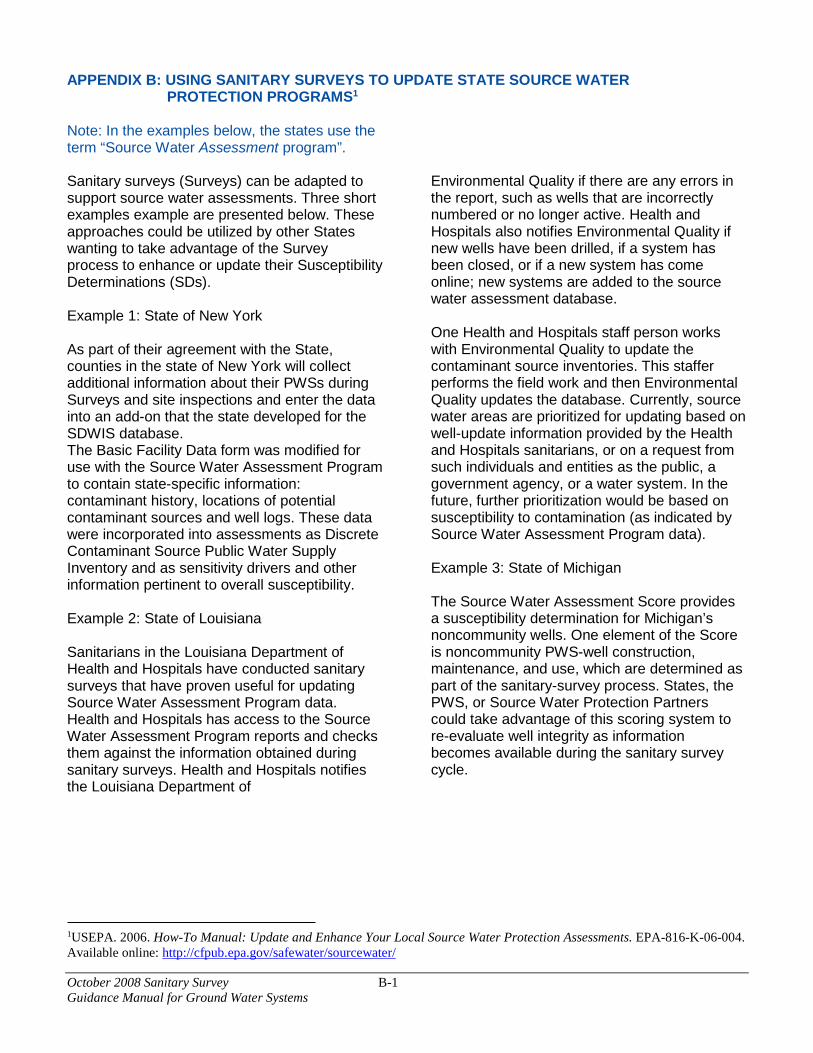
October 2008 Sanitary Survey B-1 Guidance Manual for Ground Water Systems
APPENDIX B: USING SANITARY SURVEYS TO UPDATE STATE SOURCE WATER PROTECTION PROGRAMS1
Note: In the examples below, the states use the term “Source Water Assessment program”. Sanitary surveys (Surveys) can be adapted to support source water assessments. Three short examples example are presented below. These approaches could be utilized by other States wanting to take advantage of the Survey process to enhance or update their Susceptibility Determinations (SDs). Example 1: State of New York As part of their agreement with the State, counties in the state of New York will collect additional information about their PWSs during Surveys and site inspections and enter the data into an add-on that the state developed for the SDWIS database. The Basic Facility Data form was modified for use with the Source Water Assessment Program to contain state-specific information: contaminant history, locations of potential contaminant sources and well logs. These data were incorporated into assessments as Discrete Contaminant Source Public Water Supply Inventory and as sensitivity drivers and other information pertinent to overall susceptibility. Example 2: State of Louisiana Sanitarians in the Louisiana Department of Health and Hospitals have conducted sanitary surveys that have proven useful for updating Source Water Assessment Program data. Health and Hospitals has access to the Source Water Assessment Program reports and checks them against the information obtained during sanitary surveys. Health and Hospitals notifies the Louisiana Department of
Environmental Quality if there are any errors in the report, such as wells that are incorrectly numbered or no longer active. Health and Hospitals also notifies Environmental Quality if new wells have been drilled, if a system has been closed, or if a new system has come online; new systems are added to the source water assessment database. One Health and Hospitals staff person works with Environmental Quality to update the contaminant source inventories. This staffer performs the field work and then Environmental Quality updates the database. Currently, source water areas are prioritized for updating based on well-update information provided by the Health and Hospitals sanitarians, or on a request from such individuals and entities as the public, a government agency, or a water system. In the future, further prioritization would be based on susceptibility to contamination (as indicated by Source Water Assessment Program data). Example 3: State of Michigan The Source Water Assessment Score provides a susceptibility determination for Michigan’s noncommunity wells. One element of the Score is noncommunity PWS-well construction, maintenance, and use, which are determined as part of the sanitary-survey process. States, the PWS, or Source Water Protection Partners could take advantage of this scoring system to re-evaluate well integrity as information becomes available during the sanitary survey cycle.
1USEPA. 2006. How-To Manual: Update and Enhance Your Local Source Water Protection Assessments. EPA-816-K-06-004. Available online: http://cfpub.epa.gov/safewater/sourcewater/


