Page 1
© 2008 Cisco Systems, Inc. All rights reserved. Cisco Confidential Presentation_ID 1
SANOG 14: MPLS Network Design and Deployment Workshop Agenda Srini Irigi, SPG TME, Cisco Systems, CCIE 6147 Jonny Martin, Internet Analyst, PCH
Page 2
© 2008 Cisco Systems, Inc. All rights reserved. Cisco Confidential Presentation_ID 2
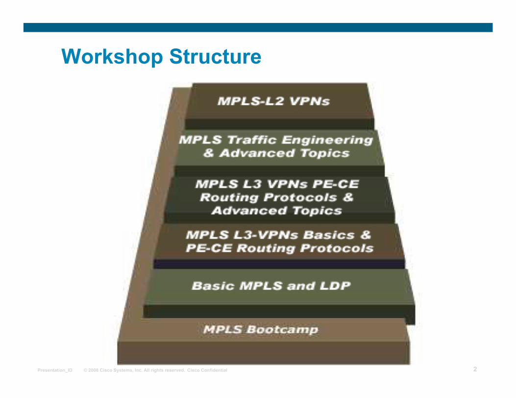
Workshop Structure
Page 3
© 2008 Cisco Systems, Inc. All rights reserved. Cisco Confidential Presentation_ID 3
Day 1 Agenda
Day 1 Modules Why MPLS is needed ???
How labels are advertised and stored What protocols are used to distribute labels Lab Overview & Initial Configuration Lab
LUNCH
LDP: LDP concepts, configuration and troubleshooting MPLS Basics Configuration Lab
Page 4
© 2008 Cisco Systems, Inc. All rights reserved. Cisco Confidential Presentation_ID 4
Day 2 Agenda
Day 2 Modules Basic concepts of VPNs MPLS L3VPNs Basic concepts Route Distinguisher, VRF and Route-Target Why MP-BGP is used between PE routers L3VPN concepts and configuration MPLS L3 VPNs Initial Configuration Lab
LUNCH
PE-CE routing protocols such as static routing Hub and Spoke L3VPN concepts and configuration BGP as a PE-CE routing protocol MPLS L3 VPNs PE-CE Basics Configuration Lab
Page 5
© 2008 Cisco Systems, Inc. All rights reserved. Cisco Confidential Presentation_ID 5
Introduction to Virtual Private Networks
Page 6
© 2008 Cisco Systems, Inc. All rights reserved. Cisco Confidential Presentation_ID 6
Outline
Overview
Traditional Router-Based Networks
Virtual Private Networks
VPN Terminology
Switched WANs VPN Terminology
Lesson Summary
Page 7
© 2008 Cisco Systems, Inc. All rights reserved. Cisco Confidential Presentation_ID 7
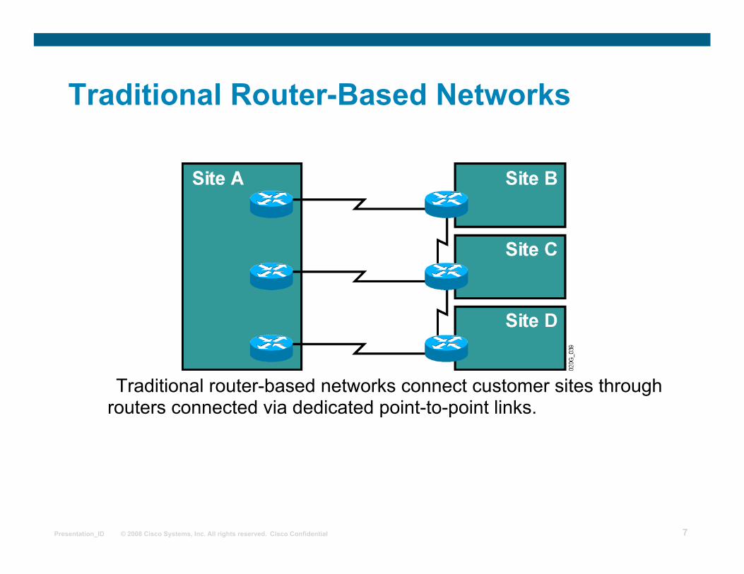
Traditional Router-Based Networks
Traditional router-based networks connect customer sites through routers connected via dedicated point-to-point links.
Page 8
© 2008 Cisco Systems, Inc. All rights reserved. Cisco Confidential Presentation_ID 8
Virtual Private Networks
• VPNs replace dedicated point-to-point links with emulated point-to-point links sharing common infrastructure.
• Customers use VPNs primarily to reduce their operational costs.
Page 9
© 2008 Cisco Systems, Inc. All rights reserved. Cisco Confidential Presentation_ID 9
VPN Terminology
Page 10
© 2008 Cisco Systems, Inc. All rights reserved. Cisco Confidential Presentation_ID 10
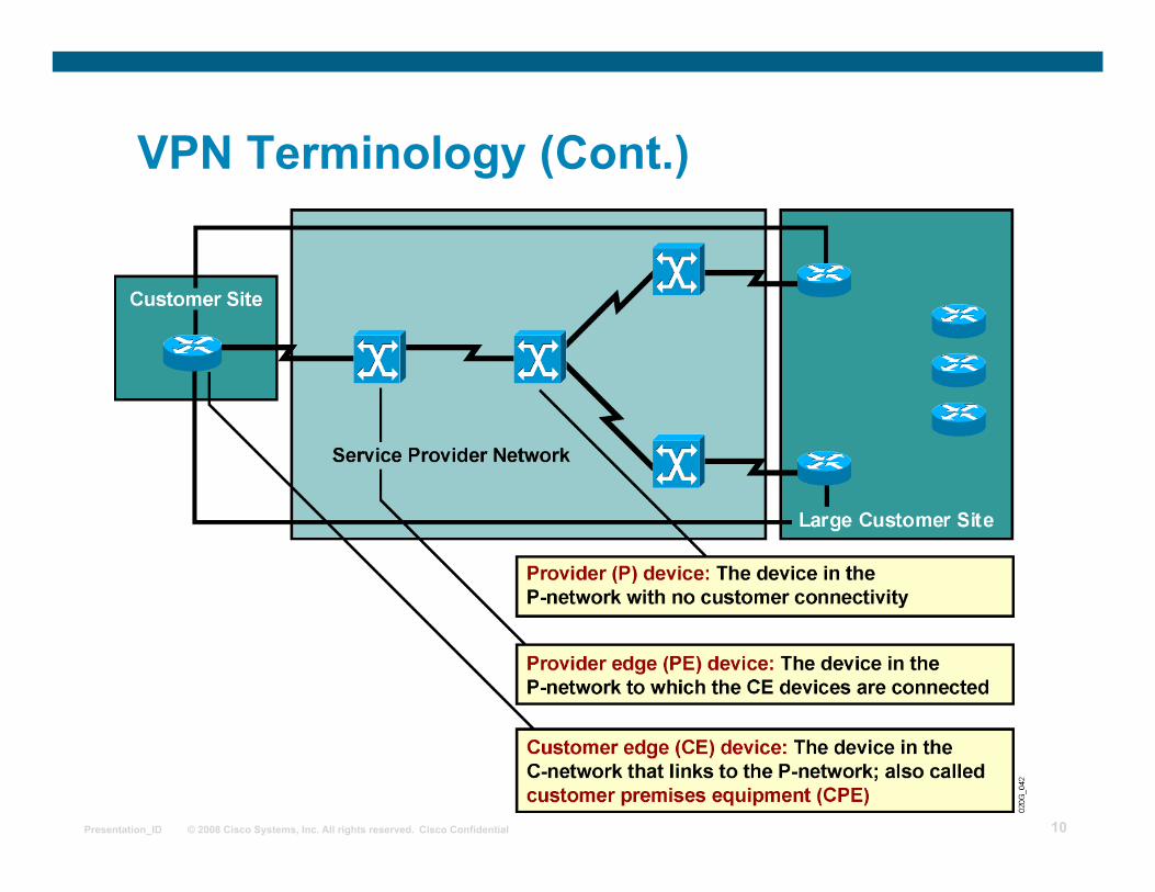
VPN Terminology (Cont.)
Page 11
© 2008 Cisco Systems, Inc. All rights reserved. Cisco Confidential Presentation_ID 11
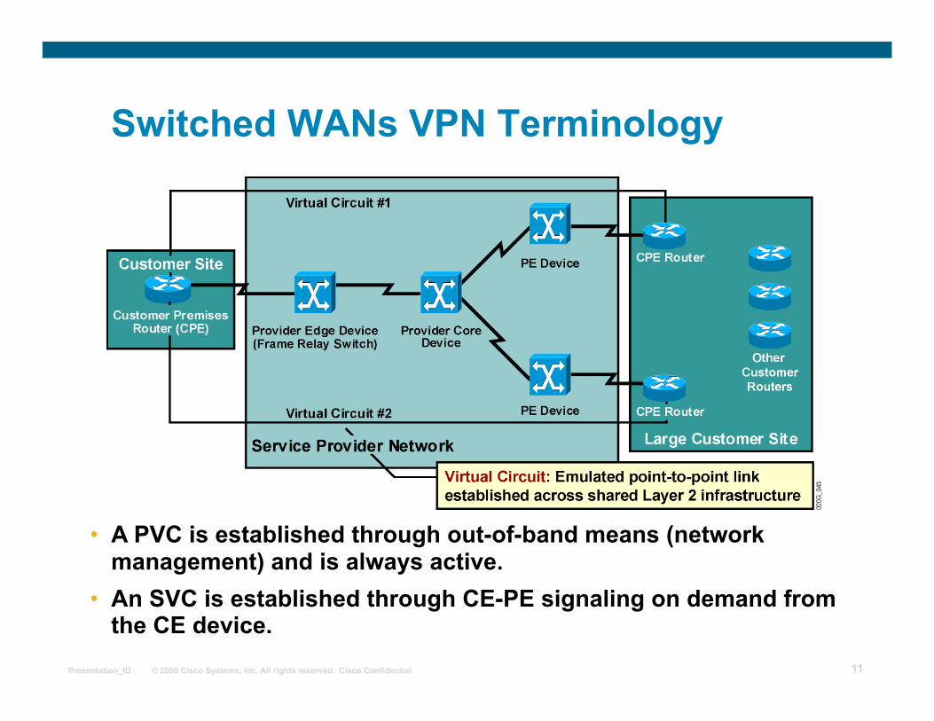
Switched WANs VPN Terminology
• A PVC is established through out-of-band means (network management) and is always active.
• An SVC is established through CE-PE signaling on demand from the CE device.
Page 12
© 2008 Cisco Systems, Inc. All rights reserved. Cisco Confidential Presentation_ID 12
Summary Traditional router-based networks connect customer sites through routers connected via dedicated point-to-point links. VPNs replaced dedicated point-to-point links with emulated point-to-point links sharing a common infrastructure. Device names based on their position in the network are as follows:
CE PE P
A PVC is established and is always active. An SVC is established through CE-PE signaling on demand from the CE device.
Page 13
© 2008 Cisco Systems, Inc. All rights reserved. Cisco Confidential Presentation_ID 13
MPLS workshop
Overlay and Peer-to-Peer VPNs
Page 14
© 2008 Cisco Systems, Inc. All rights reserved. Cisco Confidential Presentation_ID 14
Outline
Overview
VPN Implementation Technologies
Overlay VPNs
Peer-to-peer VPNs
Benefits of VPN Implementations
Drawbacks of Various VPN Implementations
Drawbacks of Traditional Peer-to-Peer VPNs
Lesson Summary
Page 15
© 2008 Cisco Systems, Inc. All rights reserved. Cisco Confidential Presentation_ID 15
VPN Implementation Technologies
VPN services can be offered based on two major models: Overlay VPNs, in which the service provider provides virtual point-to-point links between customer sites
Peer-to-peer VPNs, in which the service provider participates in the customer routing
Page 16
© 2008 Cisco Systems, Inc. All rights reserved. Cisco Confidential Presentation_ID 16
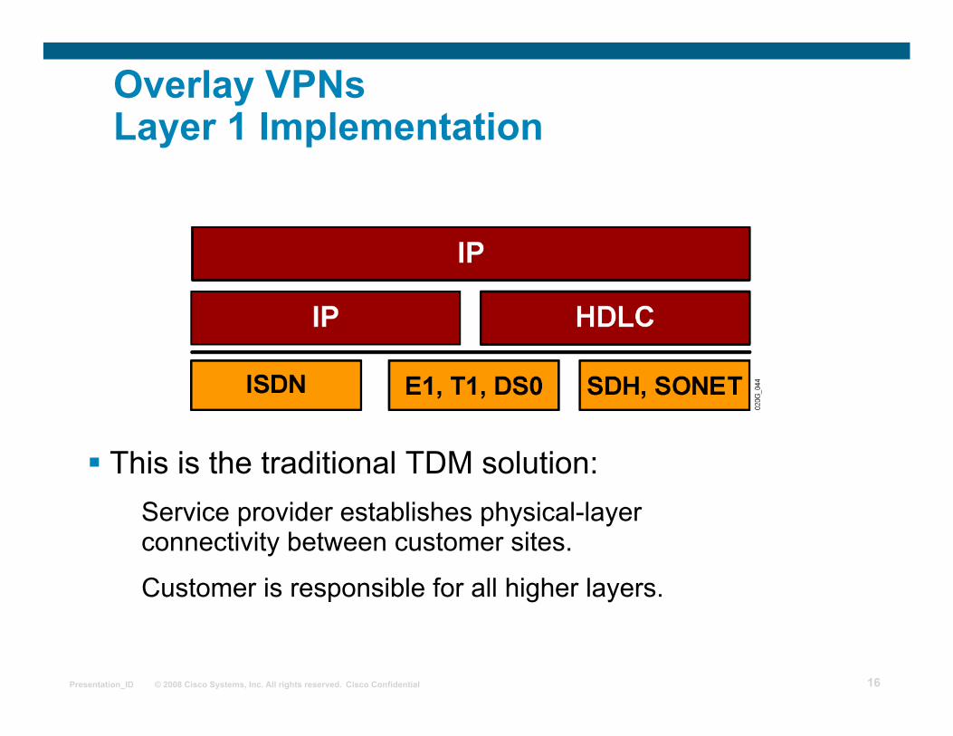
Overlay VPNs Layer 1 Implementation
This is the traditional TDM solution: Service provider establishes physical-layer connectivity between customer sites.
Customer is responsible for all higher layers.
Page 17
© 2008 Cisco Systems, Inc. All rights reserved. Cisco Confidential Presentation_ID 17
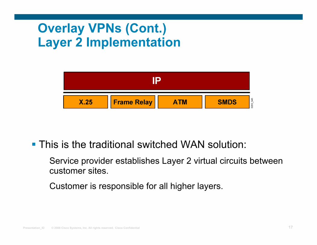
Overlay VPNs (Cont.) Layer 2 Implementation
This is the traditional switched WAN solution: Service provider establishes Layer 2 virtual circuits between customer sites.
Customer is responsible for all higher layers.
Page 18
© 2008 Cisco Systems, Inc. All rights reserved. Cisco Confidential Presentation_ID 18
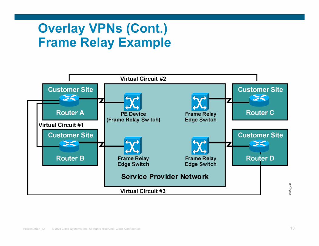
Overlay VPNs (Cont.) Frame Relay Example
Page 19
© 2008 Cisco Systems, Inc. All rights reserved. Cisco Confidential Presentation_ID 19
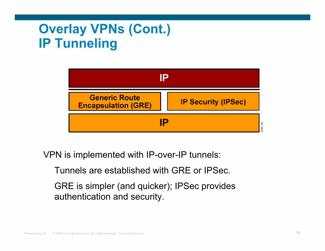
Overlay VPNs (Cont.) IP Tunneling
VPN is implemented with IP-over-IP tunnels:
Tunnels are established with GRE or IPSec.
GRE is simpler (and quicker); IPSec provides authentication and security.
Page 20
© 2008 Cisco Systems, Inc. All rights reserved. Cisco Confidential Presentation_ID 20
Overlay VPNs (Cont.) Layer 2 Forwarding
VPN is implemented with PPP-over-IP tunnels.
Usually used in access environments (dialup, digital subscriber line).
Page 21
© 2008 Cisco Systems, Inc. All rights reserved. Cisco Confidential Presentation_ID 21
Overlay VPNs (Cont.) Layer 3 Routing
Service provider infrastructure appears as point-to-point links to customer routes.
Routing protocols run directly between customer routers.
Service provider does not see customer routes and is responsible only for providing point-to-point transport of customer data.
Page 22
© 2008 Cisco Systems, Inc. All rights reserved. Cisco Confidential Presentation_ID 22
Peer-to-Peer VPNs
Page 23
© 2008 Cisco Systems, Inc. All rights reserved. Cisco Confidential Presentation_ID 23
Peer-to-Peer VPNs (Cont.) Packet Filters
Page 24
© 2008 Cisco Systems, Inc. All rights reserved. Cisco Confidential Presentation_ID 24
Benefits of VPN Implementations
Overlay VPN:
Well-known and is easy to implement.
Service provider does not participate in customer routing.
Customer network and service provider network are well isolated.
Peer-to-peer VPN:
Guarantees optimum routing between customer sites.
Easier to provision an additional VPN.
Only the sites are provisioned, not the links between them.
Page 25
© 2008 Cisco Systems, Inc. All rights reserved. Cisco Confidential Presentation_ID 25
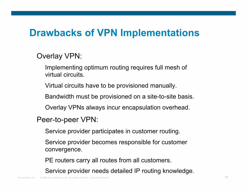
Drawbacks of VPN Implementations
Overlay VPN: Implementing optimum routing requires full mesh of virtual circuits.
Virtual circuits have to be provisioned manually.
Bandwidth must be provisioned on a site-to-site basis.
Overlay VPNs always incur encapsulation overhead.
Peer-to-peer VPN: Service provider participates in customer routing.
Service provider becomes responsible for customer convergence.
PE routers carry all routes from all customers.
Service provider needs detailed IP routing knowledge.
Page 26
© 2008 Cisco Systems, Inc. All rights reserved. Cisco Confidential Presentation_ID 26
Drawbacks of Traditional Peer-to-Peer VPNs
Shared PE router: All customers share the same (provider-assigned or public) address space.
High maintenance costs are associated with packet filters.
Performance is lower—each packet has to pass a packet filter.
Dedicated PE router: All customers share the same address space.
Each customer requires a dedicated router at each POP.
Page 27
© 2008 Cisco Systems, Inc. All rights reserved. Cisco Confidential Presentation_ID 27
Summary
The two major VPN models are overlay and peer-to-peer. Overlay VPNs can be implemented using Layer 1, Layer 2, and Layer 3 technologies. Traditional peer-to-peer VPNs are implemented using IP routing technology. Overlay VPNs use well-known technologies and are easy to implement, but require a full mesh of virtual circuits to provide optimum routing.
Page 28
© 2008 Cisco Systems, Inc. All rights reserved. Cisco Confidential Presentation_ID 28
Summary
Peer-to-peer VPNs guarantee optimum routing between customer sites but require that the service provider participates in customer routing.
Both shared PE router and dedicated PE router implementations of peer-to-peer VPNs require the customers to share a common address space.
Page 29
© 2008 Cisco Systems, Inc. All rights reserved. Cisco Confidential Presentation_ID 29
MPLS workshop
VPN Types
Page 30
© 2008 Cisco Systems, Inc. All rights reserved. Cisco Confidential Presentation_ID 30
Outline
Overview
VPN Categorization
Hub-and-Spoke Topology
Partial Mesh Overlay VPN
VPN Business Categorization
Extranet VPN
VPN Connectivity Categorization
Central Services Extranet
Managed Network Overlay VPN Implementation
Lesson Summary
Page 31
© 2008 Cisco Systems, Inc. All rights reserved. Cisco Confidential Presentation_ID 31
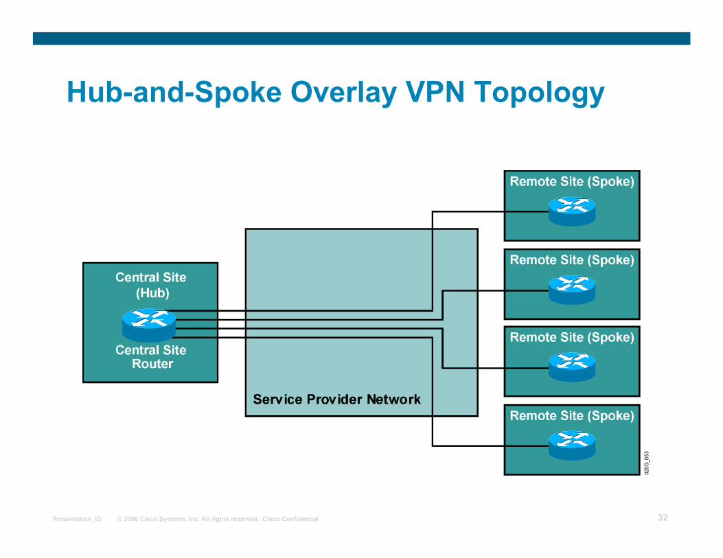
Overlay VPN Topology Category
Overlay VPNs are categorized based on the topology of the virtual circuits:
(Redundant) hub-and-spoke
Partial mesh
Full mesh
Multilevel—combines several levels of overlay VPN topologies
Page 32
© 2008 Cisco Systems, Inc. All rights reserved. Cisco Confidential Presentation_ID 32
Hub-and-Spoke Overlay VPN Topology
Page 33
© 2008 Cisco Systems, Inc. All rights reserved. Cisco Confidential Presentation_ID 33
Hub-and-Spoke Overlay VPN Topology (Cont.) Redundant Hub-and-Spoke Topology
Page 34
© 2008 Cisco Systems, Inc. All rights reserved. Cisco Confidential Presentation_ID 34
Partial Mesh Overlay VPN Topology
Page 35
© 2008 Cisco Systems, Inc. All rights reserved. Cisco Confidential Presentation_ID 35
VPN Business Category
VPNs can be categorized on the business needs that they fulfill:
Intranet VPN: Connects sites within an organization.
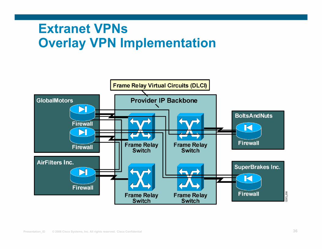
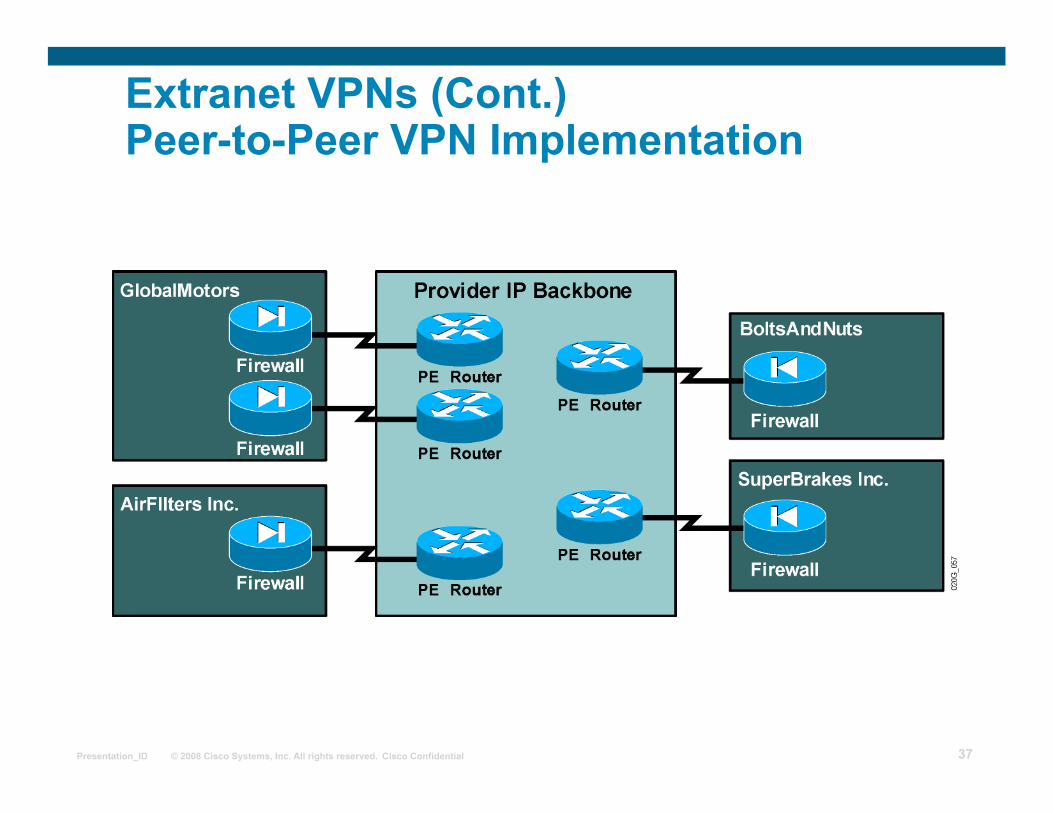
Extranet VPN: Connects different organizations in a secure way.
Access VPN: VPDN provides dialup access into a customer network.
Page 36
© 2008 Cisco Systems, Inc. All rights reserved. Cisco Confidential Presentation_ID 36
Extranet VPNs Overlay VPN Implementation
Page 37
© 2008 Cisco Systems, Inc. All rights reserved. Cisco Confidential Presentation_ID 37
Extranet VPNs (Cont.) Peer-to-Peer VPN Implementation
Page 38
© 2008 Cisco Systems, Inc. All rights reserved. Cisco Confidential Presentation_ID 38
VPN Connectivity Category
VPNs can also be categorized according to the connectivity required between sites:
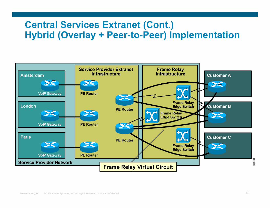
Simple VPN: Every site can communicate with every other site. Overlapping VPN: Some sites participate in more than one simple VPN. Central services VPN: All sites can communicate with central servers but not with each other. Managed network: A dedicated VPN is established to manage CE routers.
Page 39
© 2008 Cisco Systems, Inc. All rights reserved. Cisco Confidential Presentation_ID 39
Central Services Extranet
Page 40
© 2008 Cisco Systems, Inc. All rights reserved. Cisco Confidential Presentation_ID 40
Central Services Extranet (Cont.) Hybrid (Overlay + Peer-to-Peer) Implementation
Page 41
© 2008 Cisco Systems, Inc. All rights reserved. Cisco Confidential Presentation_ID 41
Managed Network Overlay VPN Implementation
Page 42
© 2008 Cisco Systems, Inc. All rights reserved. Cisco Confidential Presentation_ID 42
Summary
Major VPN topologies consist of the following:
Hub-and-spoke – simplest topology
Partial mesh – cost/complexity factors dictate
Full mesh – connections between all sites
Multilevel – can be used for large-scale networks VPNs can be based on business needs:
Intranet
Extranet
Access
Page 43
© 2008 Cisco Systems, Inc. All rights reserved. Cisco Confidential Presentation_ID 43
MPLS workshop
MPLS VPN Architecture
Page 44
© 2008 Cisco Systems, Inc. All rights reserved. Cisco Confidential Presentation_ID 44
Outline Overview
MPLS VPN Architecture
PE Router Architecture
Propagation Routing Information across the P-network
Route Distinguishers
Route Targets
Virtual Private Networks Redefined
Impact of Complex VPN Topologies on Virtual Routing Tables
Lesson Summary
Page 45
© 2008 Cisco Systems, Inc. All rights reserved. Cisco Confidential Presentation_ID 45
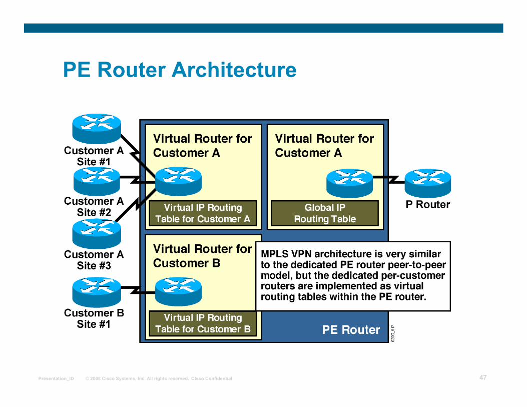
MPLS VPN Architecture
An MPLS VPN combines the best features of an overlay VPN and a peer-to-peer VPN:
PE routers participate in customer routing, guaranteeing optimum routing between sites and easy provisioning.
PE routers carry a separate set of routes for each customer (similar to the dedicated PE router approach).
Customers can use overlapping addresses.
Page 46
© 2008 Cisco Systems, Inc. All rights reserved. Cisco Confidential Presentation_ID 46
MPLS VPN Architecture (Cont.) Terminology
Page 47
© 2008 Cisco Systems, Inc. All rights reserved. Cisco Confidential Presentation_ID 47
PE Router Architecture
Page 48
© 2008 Cisco Systems, Inc. All rights reserved. Cisco Confidential Presentation_ID 48
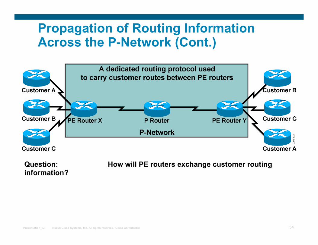
Propagation of Routing Information Across the P-Network
Question: How will PE routers exchange customer routing information?
Page 49
© 2008 Cisco Systems, Inc. All rights reserved. Cisco Confidential Presentation_ID 49
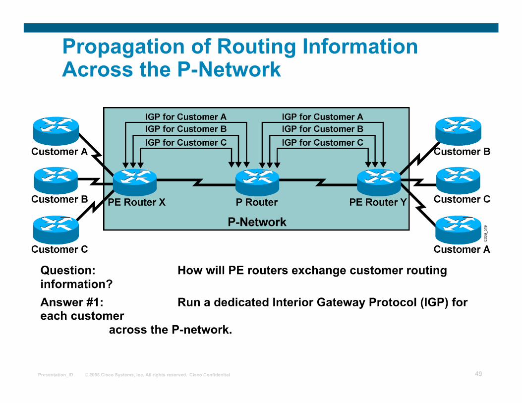
Propagation of Routing Information Across the P-Network
Question: How will PE routers exchange customer routing information? Answer #1: Run a dedicated Interior Gateway Protocol (IGP) for each customer across the P-network.
Page 50
© 2008 Cisco Systems, Inc. All rights reserved. Cisco Confidential Presentation_ID 50
Propagation of Routing Information Across the P-Network
Question: How will PE routers exchange customer routing information? Answer #1: Run a dedicated Interior Gateway Protocol (IGP) for each customer across the P-network.
This is the wrong answer for the following reasons: • The solution does not scale. • P routers carry all customer routes.
Page 51
© 2008 Cisco Systems, Inc. All rights reserved. Cisco Confidential Presentation_ID 51
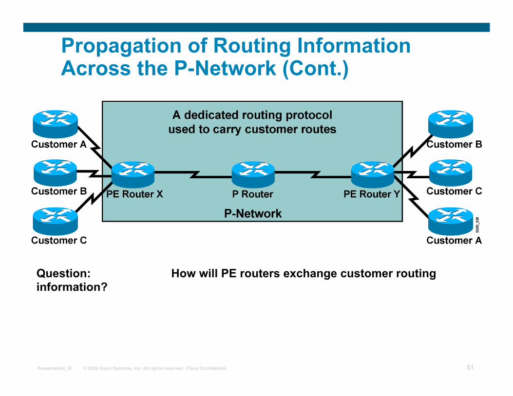
Propagation of Routing Information Across the P-Network (Cont.)
Question: How will PE routers exchange customer routing information?
Page 52
© 2008 Cisco Systems, Inc. All rights reserved. Cisco Confidential Presentation_ID 52
Propagation of Routing Information Across the P-Network (Cont.)
Question: How will PE routers exchange customer routing information? Answer #2: Run a single routing protocol that will carry all customer routes
inside the provider backbone.
Page 53
© 2008 Cisco Systems, Inc. All rights reserved. Cisco Confidential Presentation_ID 53
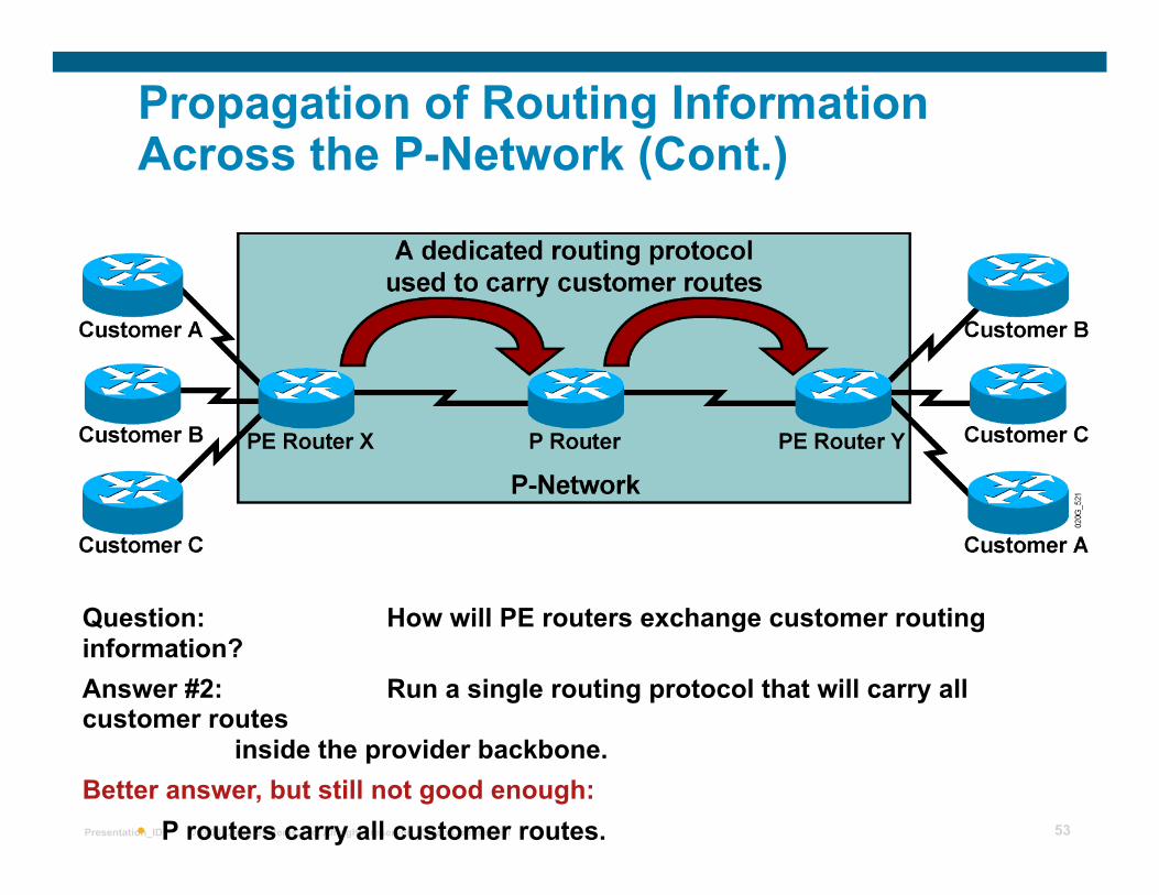
Propagation of Routing Information Across the P-Network (Cont.)
Question: How will PE routers exchange customer routing information? Answer #2: Run a single routing protocol that will carry all customer routes
inside the provider backbone. Better answer, but still not good enough:
• P routers carry all customer routes.
Page 54
© 2008 Cisco Systems, Inc. All rights reserved. Cisco Confidential Presentation_ID 54
Propagation of Routing Information Across the P-Network (Cont.)
Question: How will PE routers exchange customer routing information?
Page 55
© 2008 Cisco Systems, Inc. All rights reserved. Cisco Confidential Presentation_ID 55
Propagation of Routing Information Across the P-Network (Cont.)
Question: How will PE routers exchange customer routing information? Answer #3: Run a single routing protocol that will carry all customer routes between PE routers. Use MPLS labels to exchange packets
between PE routers.
Page 56
© 2008 Cisco Systems, Inc. All rights reserved. Cisco Confidential Presentation_ID 56
Propagation of Routing Information Across the P-Network (Cont.)
Question: How will PE routers exchange customer routing information? Answer #3: Run a single routing protocol that will carry all customer routes between PE routers. Use MPLS labels to exchange packets
between PE routers. The best answer: • P routers do not carry customer routes; the solution is scalable.
Page 57
© 2008 Cisco Systems, Inc. All rights reserved. Cisco Confidential Presentation_ID 57
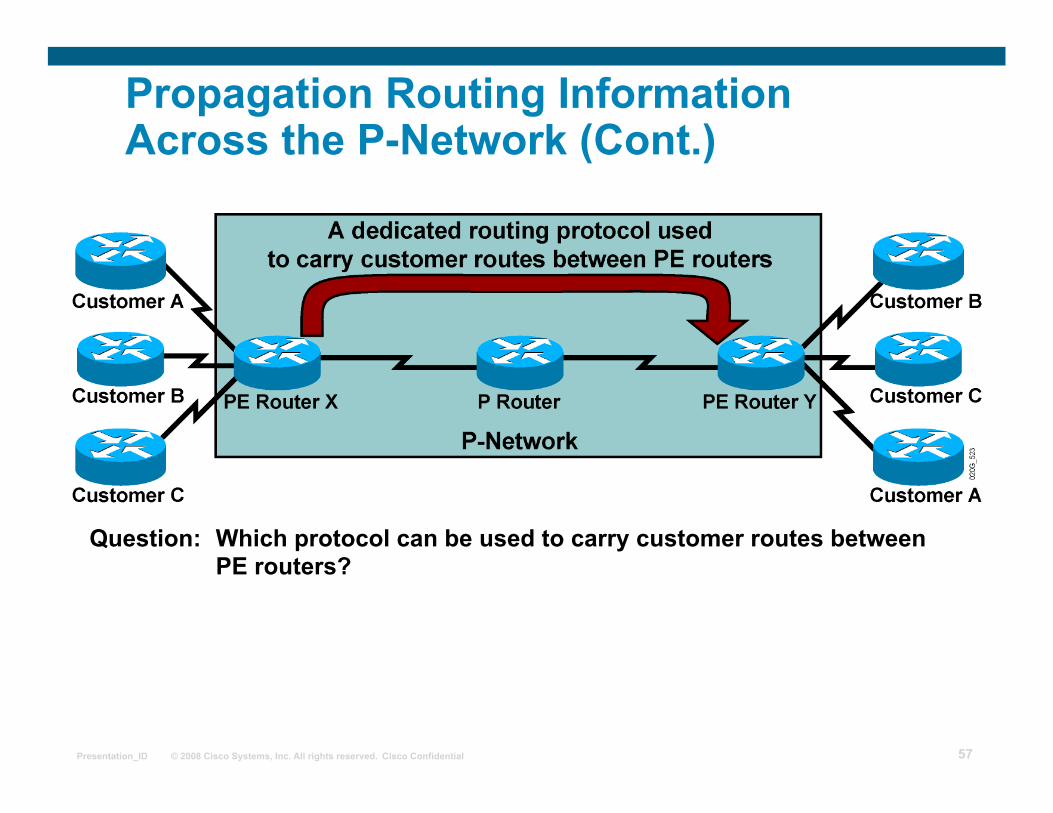
Propagation Routing Information Across the P-Network (Cont.)
Question: Which protocol can be used to carry customer routes between PE routers?
Page 58
© 2008 Cisco Systems, Inc. All rights reserved. Cisco Confidential Presentation_ID 58
Propagation Routing Information Across the P-Network (Cont.)
Question: Which protocol can be used to carry customer routes between PE routers?
Answer: The number of customer routes can be very large. BGP is the only routing protocol that can scale to a very large number of routes.
Page 59
© 2008 Cisco Systems, Inc. All rights reserved. Cisco Confidential Presentation_ID 59
Propagation Routing Information Across the P-Network (Cont.)
Question: Which protocol can be used to carry customer routes between PE routers?
Answer: The number of customer routes can be very large. BGP is the only routing protocol that can scale to a very large number of routes.
Conclusion: BGP is used to exchange customer routes directly between PE routers.
Page 60
© 2008 Cisco Systems, Inc. All rights reserved. Cisco Confidential Presentation_ID 60
Propagation of Routing Information Across the P-Network (Cont.)
Question: How will information about the overlapping subnets of two customers be propagated via a single routing protocol?
Page 61
© 2008 Cisco Systems, Inc. All rights reserved. Cisco Confidential Presentation_ID 61
Propagation of Routing Information Across the P-Network (Cont.)
Question: How will information about the overlapping subnets of two customers be propagated via a single routing protocol?
Answer: Extend the customer addresses to make them unique.
Page 62
© 2008 Cisco Systems, Inc. All rights reserved. Cisco Confidential Presentation_ID 62
Route Distinguishers
The 64-bit route distinguisher (RD) is prepended to an IPv4 address to make it globally unique.
The resulting address is a VPNv4 address.
VPNv4 addresses are exchanged between PE routers via BGP.
BGP that supports address families other than IPv4 addresses is called Multiprotocol BGP (MP-BGP).
100:1
12 Bytes
RD + IPv4
VPNv4 Address
10.10.10.0
Page 63
© 2008 Cisco Systems, Inc. All rights reserved. Cisco Confidential Presentation_ID 63
Route Distinguishers (Cont.)
8 Bytes
Autonomous System VPN Identifier
IP Address VPN Identifier
Route Distinguisher Format
Service Providers can use their BGP AS along with VPN customer identifier
Service Provider who do not have BGP AS, can use an IP address
Page 64
© 2008 Cisco Systems, Inc. All rights reserved. Cisco Confidential Presentation_ID 64
Route Distinguishers (Cont.)
Customer A has RD of 100:1
Customer B has RD of 100:2
Route Distinguisher keeps Customer A’s update unique from Customer B in the MP-iBGP update, although they use the same IP address
100:1
VPNv4 Addresses
10.10.10.0
100:2 10.10.10.0
MP-iBGP update
Page 65
© 2008 Cisco Systems, Inc. All rights reserved. Cisco Confidential Presentation_ID 65
Route Distinguishers (Cont.)
Page 66
© 2008 Cisco Systems, Inc. All rights reserved. Cisco Confidential Presentation_ID 66
Route Distinguishers (Cont.)
Page 67
© 2008 Cisco Systems, Inc. All rights reserved. Cisco Confidential Presentation_ID 67
Route Distinguishers (Cont.)
Page 68
© 2008 Cisco Systems, Inc. All rights reserved. Cisco Confidential Presentation_ID 68
Route Distinguishers (Cont.)
Page 69
© 2008 Cisco Systems, Inc. All rights reserved. Cisco Confidential Presentation_ID 69
Route Distinguishers (Cont.)
Page 70
© 2008 Cisco Systems, Inc. All rights reserved. Cisco Confidential Presentation_ID 70
Route Distinguishers (Cont.) Usage in an MPLS VPN
The RD has no special meaning.
Used only to make potentially overlapping IPv4 addresses globally unique.
The RD could serve as a VPN identifier, but this design could not support all topologies required by the customers.
Page 71
© 2008 Cisco Systems, Inc. All rights reserved. Cisco Confidential Presentation_ID 71
Route Targets VoIP Service Sample
Why is RD not enough to identify VPNs?
Page 72
© 2008 Cisco Systems, Inc. All rights reserved. Cisco Confidential Presentation_ID 72
Route Targets VoIP Service Sample
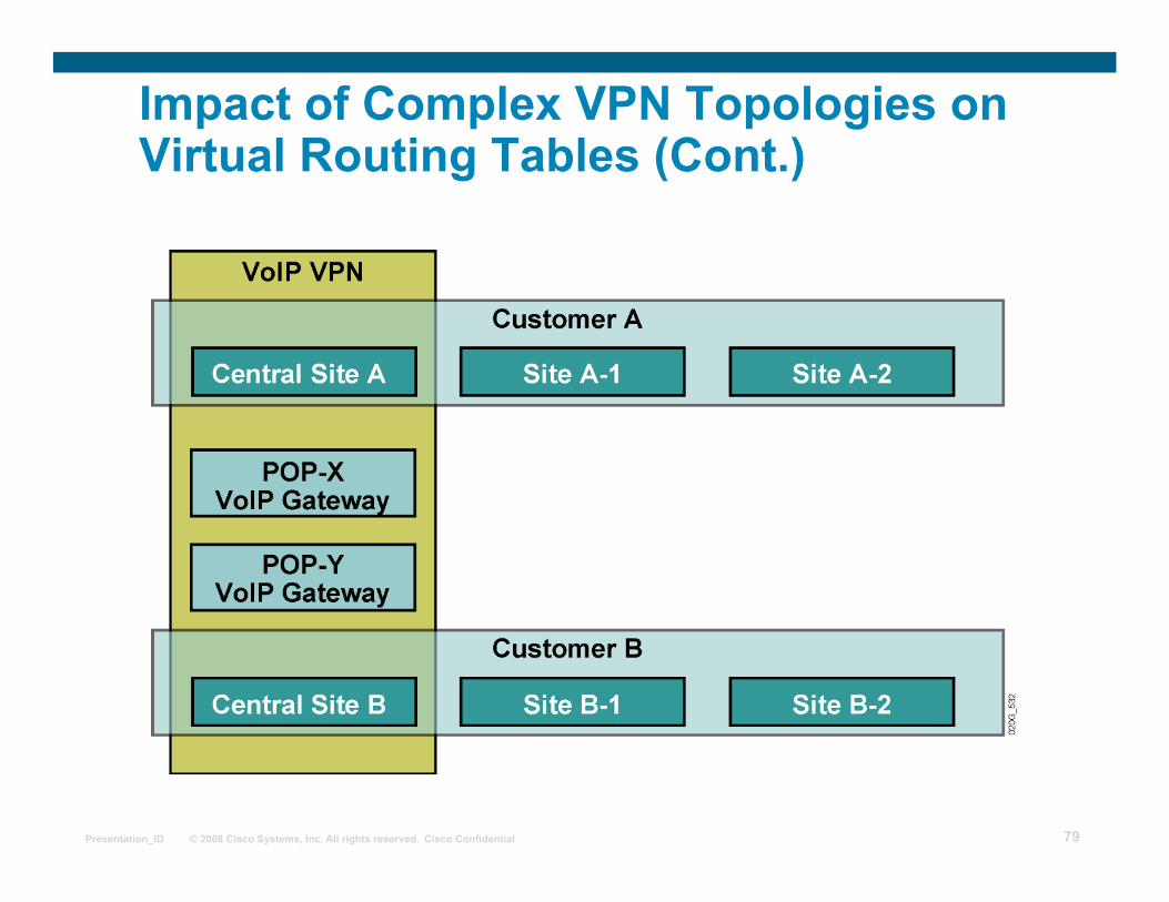
Requirements: • All sites of one customer need to communicate. • Central sites of both customers need to communicate with VoIP
gateways and other central sites. • Other sites from different customers do not communicate with each other.
Page 73
© 2008 Cisco Systems, Inc. All rights reserved. Cisco Confidential Presentation_ID 73
Route Targets (Cont.) Connectivity Requirements
Page 74
© 2008 Cisco Systems, Inc. All rights reserved. Cisco Confidential Presentation_ID 74
Route Targets (Cont.) Why Are They Needed?
Some sites have to participate in more than one VPN.
The RD cannot identify participation in more than one VPN.
RTs were introduced in the MPLS VPN architecture to support complex VPN topologies.
A different method is needed in which a set of identifiers can be attached to a route.
Page 75
© 2008 Cisco Systems, Inc. All rights reserved. Cisco Confidential Presentation_ID 75
Route Targets (Cont.) What Are They?
RTs are additional attributes attached to VPNv4 BGP routes to indicate VPN membership.
Format is same as Route Distinguisher
Extended BGP communities are used to encode these attributes.
Extended communities carry the meaning of the attribute together with its value.
Any number of RTs can be attached to a single route.
VPNv4 update
100:2 10.10.10.0
MP-iBGP update
Route-Targets
Customer B: 2 VoIP VPN: 2
Page 76
© 2008 Cisco Systems, Inc. All rights reserved. Cisco Confidential Presentation_ID 76
Route Targets (Cont.) How Do They Work?
Export RTs: Identifying VPN membership Appended to the customer route when it is converted into a VPNv4 route
Import RTs: Associated with each virtual routing table Select routes to be inserted into the virtual routing table
Page 77
© 2008 Cisco Systems, Inc. All rights reserved. Cisco Confidential Presentation_ID 77
Virtual Private Networks Redefined
With the introduction of complex VPN topologies, VPNs have had to be redefined:
A VPN is a collection of sites sharing common routing information.
A site can be part of different VPNs.
A VPN can be seen as a community of interest (closed user group, or CUG).
Complex VPN topologies are supported by multiple virtual routing tables on the PE routers.
Page 78
© 2008 Cisco Systems, Inc. All rights reserved. Cisco Confidential Presentation_ID 78
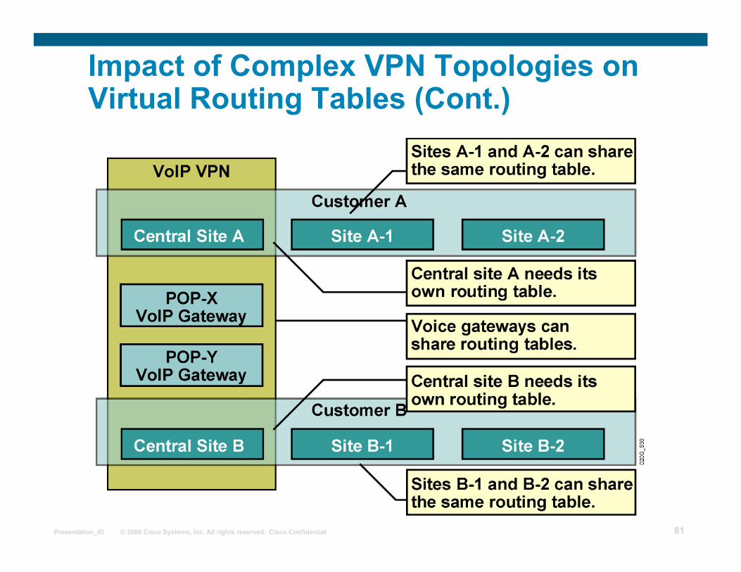
Impact of Complex VPN Topologies on Virtual Routing Tables
A virtual routing table in a PE router can be used only for sites with identical connectivity requirements.
Complex VPN topologies require more than one virtual routing table per VPN.
As each virtual routing table requires a distinct RD value, the number of RDs in the MPLS VPN network increases.
Page 79
© 2008 Cisco Systems, Inc. All rights reserved. Cisco Confidential Presentation_ID 79
Impact of Complex VPN Topologies on Virtual Routing Tables (Cont.)
Page 80
© 2008 Cisco Systems, Inc. All rights reserved. Cisco Confidential Presentation_ID 80
Impact of Complex VPN Topologies on Virtual Routing Tables (Cont.)
Page 81
© 2008 Cisco Systems, Inc. All rights reserved. Cisco Confidential Presentation_ID 81
Impact of Complex VPN Topologies on Virtual Routing Tables (Cont.)
Page 82
© 2008 Cisco Systems, Inc. All rights reserved. Cisco Confidential Presentation_ID 82
Important points to note for RT and RD
Route Distinguishers (RD) are only used to make ipv4 VPN addresses unique when advertising them over MP-iBGP, by making them vpnv4 prefixes
We can have one RD per vrf
Only one vrf can be assigned to an interface
Route Targets (RT) are used for VPN membership, so that complex scenarios can be addressed
VPN is the set of rules for customer connectivity and can be very complex
A VPN may have several RTs
Page 83
© 2008 Cisco Systems, Inc. All rights reserved. Cisco Confidential Presentation_ID 83
Summary
MPLS VPN architecture combines the best features of the overlay and peer-to-peer VPN models.
Virtual routing tables are created for each customer.
BGP is used to exchange customer routes between PE routers.
Route distinguishers transform non-unique 32-bit addresses into 96-bit unique addresses.
Route targets are used to identify VPN membership in overlapping topologies.
Placing sites with different routing requirements in the same virtual routing table will result in inconsistent routing.
Page 84
© 2008 Cisco Systems, Inc. All rights reserved. Cisco Confidential Presentation_ID 84
MPLS workshop
MPLS VPN Routing Model
Page 85
© 2008 Cisco Systems, Inc. All rights reserved. Cisco Confidential Presentation_ID 85
Outline
Overview MPLS VPN Routing Requirements MPLS VPN Routing Support for Existing Internet Routing Routing Tables on PE Routers End-to-End Routing Update Flow Route Distribution to CE Routers Lesson Summary
Page 86
© 2008 Cisco Systems, Inc. All rights reserved. Cisco Confidential Presentation_ID 86
MPLS VPN Routing Requirements
CE routers have to run standard IP routing software.
PE routers have to support MPLS VPN services and Internet routing.
P routers have no VPN routes.
Page 87
© 2008 Cisco Systems, Inc. All rights reserved. Cisco Confidential Presentation_ID 87
MPLS VPN Routing CE Router Perspective
The CE routers run standard IP routing software and exchange routing updates with the PE router.
PE-CE protocols can be EBGP, OSPF, RIPv2, EIGRP, and static routes. ISIS support in the works
The PE router appears as another router in the C-network.
Page 88
© 2008 Cisco Systems, Inc. All rights reserved. Cisco Confidential Presentation_ID 88
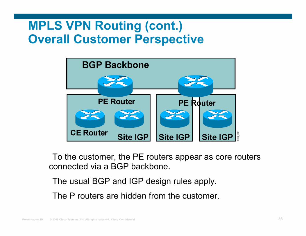
MPLS VPN Routing (cont.) Overall Customer Perspective
To the customer, the PE routers appear as core routers connected via a BGP backbone.
The usual BGP and IGP design rules apply.
The P routers are hidden from the customer.
Page 89
© 2008 Cisco Systems, Inc. All rights reserved. Cisco Confidential Presentation_ID 89
MPLS VPN Routing (Cont.) P Router Perspective
• P routers do not participate in MPLS VPN routing and do not carry VPN routes.
• P routers run backbone IGP with the PE routers and exchange information about global subnets (core links and loopbacks).
Page 90
© 2008 Cisco Systems, Inc. All rights reserved. Cisco Confidential Presentation_ID 90
• Exchange VPN routes with CE routers via per-VPN routing protocols
MPLS VPN Routing (Cont.) PE Router Perspective
Exchange VPNv4 routes with other PE routers via MP-IBGP sessions
PE routers:
• Exchange core routes with P routers and PE routers via core IGP
Page 91
© 2008 Cisco Systems, Inc. All rights reserved. Cisco Confidential Presentation_ID 91
Support for Existing Internet Routing
PE routers can run standard IPv4 BGP in the global routing table: PE routers exchange Internet routes with other PE routers.
CE routers do not participate in Internet routing.
P routers do not need to participate in Internet routing.
Page 92
© 2008 Cisco Systems, Inc. All rights reserved. Cisco Confidential Presentation_ID 92
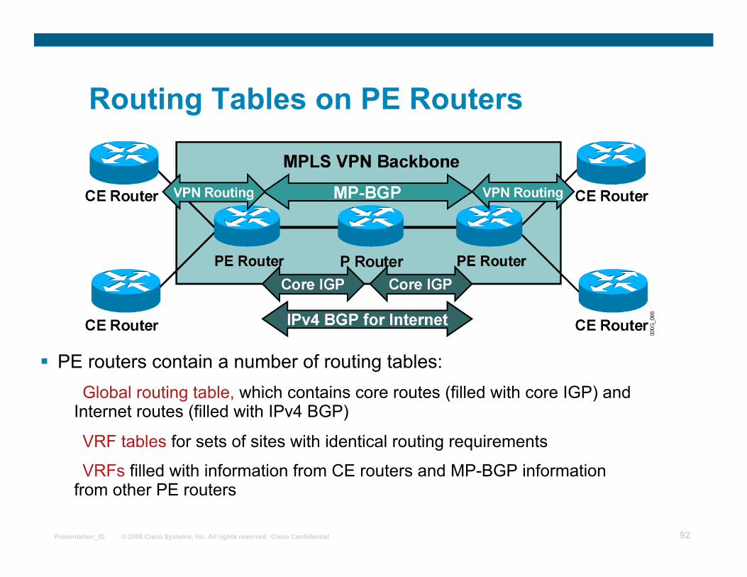
Routing Tables on PE Routers
PE routers contain a number of routing tables: Global routing table, which contains core routes (filled with core IGP) and
Internet routes (filled with IPv4 BGP)
VRF tables for sets of sites with identical routing requirements
VRFs filled with information from CE routers and MP-BGP information from other PE routers
Page 93
© 2008 Cisco Systems, Inc. All rights reserved. Cisco Confidential Presentation_ID 93
End-to-End Routing Update Flow
• PE routers receive IPv4 routing updates from CE routers and install them in the appropriate VRF table.
Page 94
© 2008 Cisco Systems, Inc. All rights reserved. Cisco Confidential Presentation_ID 94
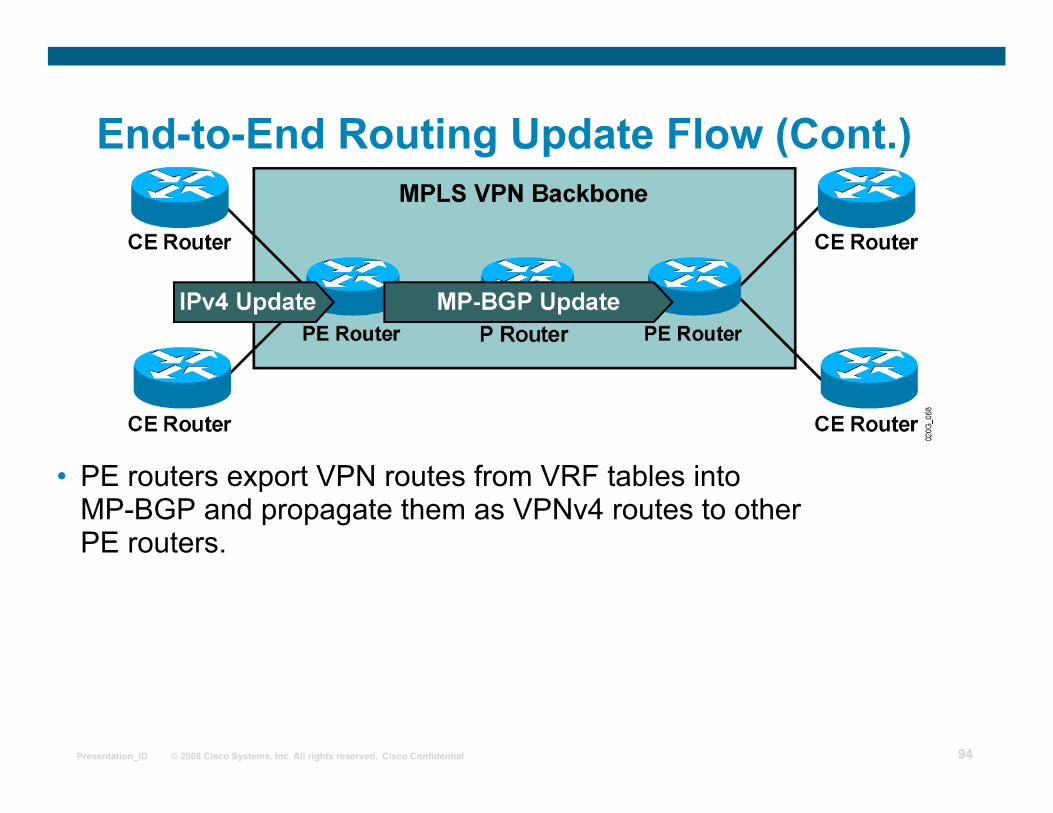
End-to-End Routing Update Flow (Cont.)
• PE routers export VPN routes from VRF tables into MP-BGP and propagate them as VPNv4 routes to other PE routers.
Page 95
© 2008 Cisco Systems, Inc. All rights reserved. Cisco Confidential Presentation_ID 95
End-to-End Routing Update Flow (Cont.) MP-BGP Update
An MP-BGP update contains the following: VPNv4 address
Extended communities (route targets, optionally SOO)
Label used for VPN packet forwarding
Any other BGP attribute (for example, AS path, local preference, MED, standard community)
Page 96
© 2008 Cisco Systems, Inc. All rights reserved. Cisco Confidential Presentation_ID 96
End-to-End Routing Update Flow (Cont.)
• Receiving PE router imports incoming VPNv4 routes into the appropriate VRF based on route targets attached to the routes.
• Routes installed in VRF are propagated to CE routers.
Page 97
© 2008 Cisco Systems, Inc. All rights reserved. Cisco Confidential Presentation_ID 97
Route Distribution to CE Routers
Route distribution to sites is driven by the following:
SOO
RT BGP communities
A route is installed in the site VRF that matches the RT attribute.
Page 98
© 2008 Cisco Systems, Inc. All rights reserved. Cisco Confidential Presentation_ID 98
Summary
MPLS VPNs technology does the following: Supports the use of standard IP routing between devices Provides scalable solutions Supports both MPLS VPNs and traditional Internet services
The internal service provider topology is transparent to the customer. PE routers alone see all routing aspects of the MPLS VPN. VRF tables contain sets of routes for sites with identical routing requirements. Routes are transported using the following:
IGP (internal core routes) BGP IPv4 (core Internet routes) BGP VPNv4 (PE-to-PE VPN routes)
Page 99
© 2008 Cisco Systems, Inc. All rights reserved. Cisco Confidential Presentation_ID 99
MPLS workshop
MPLS VPN Packet Forwarding
Page 100
© 2008 Cisco Systems, Inc. All rights reserved. Cisco Confidential Presentation_ID 100
Outline
Overview
VPN Packet Forwarding Across an MPLS VPN Backbone
VPN Penultimate Hop Popping
VPN Label Propagation
MPLS VPN and Label Propagation
MPLS VPN and Packet Forwarding
Lesson Summary
Page 101
© 2008 Cisco Systems, Inc. All rights reserved. Cisco Confidential Presentation_ID 101
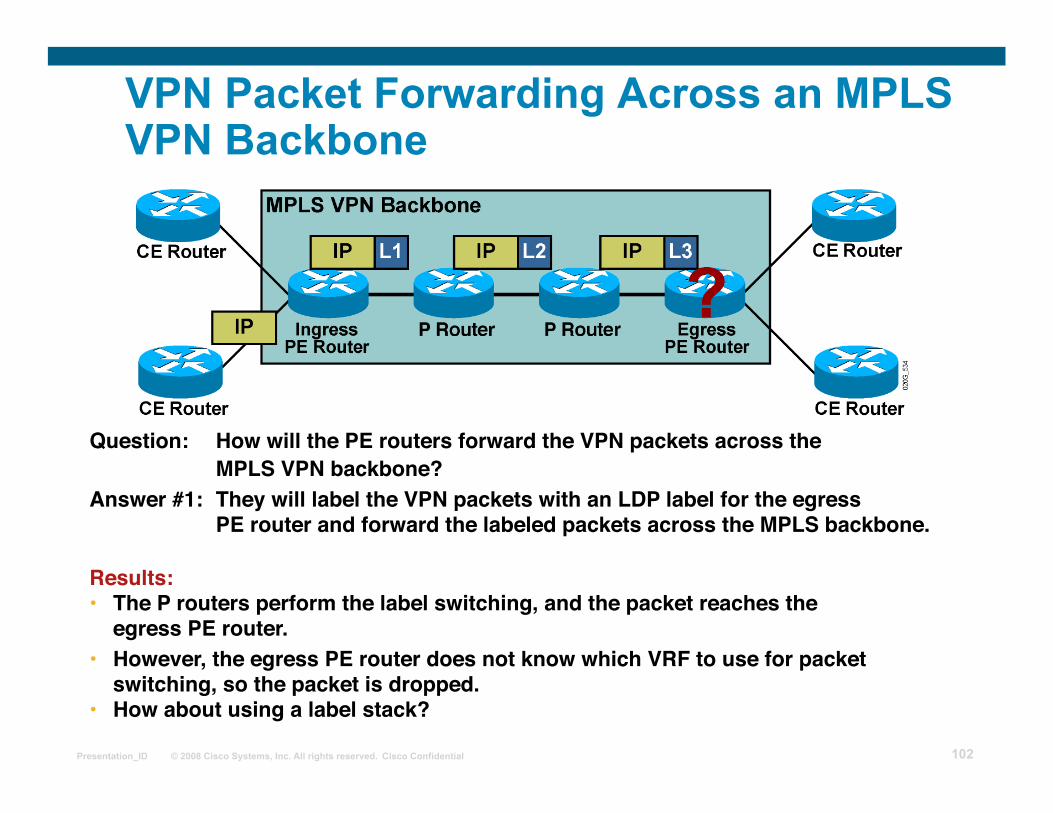
VPN Packet Forwarding Across an MPLS VPN Backbone
Question: How will the PE routers forward the VPN packets across the MPLS VPN backbone?
Answer #1: They will label the VPN packets with an LDP label for the egress PE router and forward the labeled packets across the MPLS backbone.
Page 102
© 2008 Cisco Systems, Inc. All rights reserved. Cisco Confidential Presentation_ID 102
VPN Packet Forwarding Across an MPLS VPN Backbone
Question: How will the PE routers forward the VPN packets across the MPLS VPN backbone?
• However, the egress PE router does not know which VRF to use for packet switching, so the packet is dropped.
• How about using a label stack?
Answer #1: They will label the VPN packets with an LDP label for the egress PE router and forward the labeled packets across the MPLS backbone.
Results: • The P routers perform the label switching, and the packet reaches the egress PE router.
Page 103
© 2008 Cisco Systems, Inc. All rights reserved. Cisco Confidential Presentation_ID 103
VPN Packet Forwarding Across an MPLS VPN Backbone (Cont.)
Question: How will the PE routers forward the VPN packets across the MPLS VPN backbone?
Answer #2: They will label the VPN packets with a label stack, using the LDP label for the egress PE router as the top label, and the VPN label assigned by the egress PE router as the second label in the stack.
Page 104
© 2008 Cisco Systems, Inc. All rights reserved. Cisco Confidential Presentation_ID 104
VPN Packet Forwarding Across an MPLS VPN Backbone (Cont.)
Question: How will the PE routers forward the VPN packets across the MPLS VPN backbone?
Result: • The P routers perform label switching, and the packet reaches the egress PE router.
• The egress PE router performs a lookup on the VPN label and forwards the packet toward the CE router.
Answer #2: They will label the VPN packets with a label stack, using the LDP label for the egress PE router as the top label, and the VPN label assigned by the egress PE router as the second label in the stack.
Page 105
© 2008 Cisco Systems, Inc. All rights reserved. Cisco Confidential Presentation_ID 105
VPN Penultimate Hop Popping
• The egress PE router performs label lookup only on the VPN label, resulting in faster and simpler label lookup.
• IP lookup is performed only once—in the ingress PE router.
• Penultimate hop popping on the LDP label can be performed on the last P router.
Page 106
© 2008 Cisco Systems, Inc. All rights reserved. Cisco Confidential Presentation_ID 106
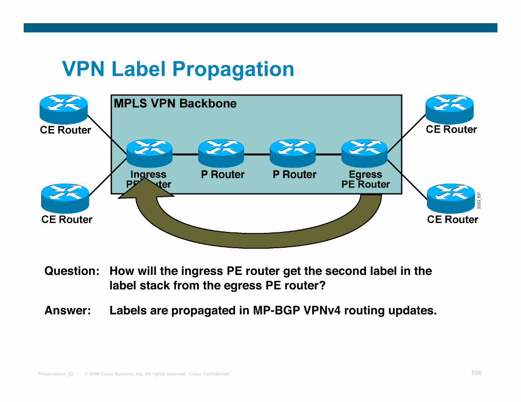
VPN Label Propagation
Question: How will the ingress PE router get the second label in the label stack from the egress PE router?
Answer: Labels are propagated in MP-BGP VPNv4 routing updates.
Page 107
© 2008 Cisco Systems, Inc. All rights reserved. Cisco Confidential Presentation_ID 107
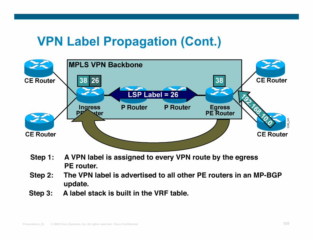
Step 1: A VPN label is assigned to every VPN route by the egressPE router.
VPN Label Propagation (Cont.)
Page 108
© 2008 Cisco Systems, Inc. All rights reserved. Cisco Confidential Presentation_ID 108
Step 1: A VPN label is assigned to every VPN route by the egressPE router.
VPN Label Propagation (Cont.)
Step 2: The VPN label is advertised to all other PE routers in an MP-BGPupdate.
Page 109
© 2008 Cisco Systems, Inc. All rights reserved. Cisco Confidential Presentation_ID 109
Step 1: A VPN label is assigned to every VPN route by the egressPE router.
VPN Label Propagation (Cont.)
Step 2: The VPN label is advertised to all other PE routers in an MP-BGPupdate.
Step 3: A label stack is built in the VRF table.
Page 110
© 2008 Cisco Systems, Inc. All rights reserved. Cisco Confidential Presentation_ID 110
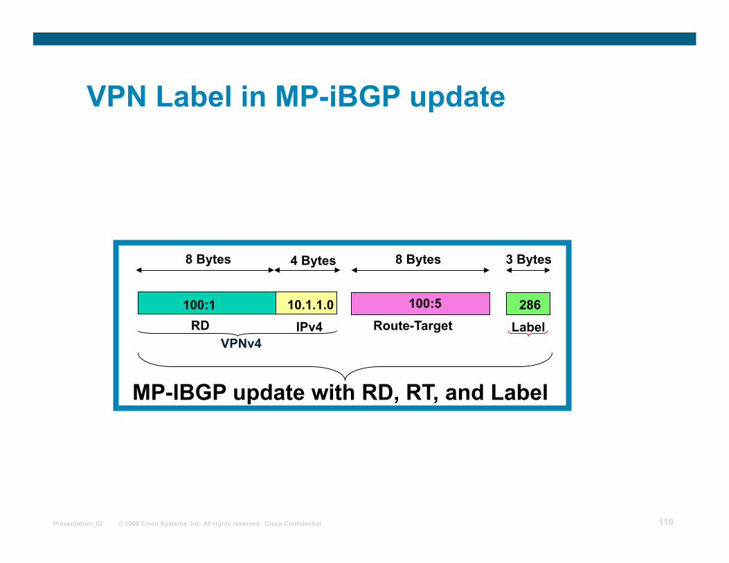
8 Bytes
Route-Target
3 Bytes
Label
MP-IBGP update with RD, RT, and Label
100:1
8 Bytes 4 Bytes
RD IPv4 VPNv4
10.1.1.0 100:5 286
VPN Label in MP-iBGP update
Page 111
© 2008 Cisco Systems, Inc. All rights reserved. Cisco Confidential Presentation_ID 111
MPLS VPNs and Label Propagation
The VPN label must be assigned by the BGP next hop. The BGP next hop should not be changed in the MP-IBGP update propagation.
Do not use next-hop-self on confederation boundaries. The PE router must be the BGP next hop.
Use next-hop-self on the PE router (default on current IOS)
The label must be reoriginated if the next hop is changed. A new label is assigned every time that the MP-BGP update crosses the AS boundary where the next hop is changed.
Page 112
© 2008 Cisco Systems, Inc. All rights reserved. Cisco Confidential Presentation_ID 112
MPLS VPNs and Packet Forwarding
The VPN label is understood only by the egress PE router. An end-to-end LSP tunnel is required between the ingress and egress PE routers. BGP next hops must not be announced as BGP routes. LDP labels are not assigned to BGP routes. BGP next hops announced in IGP must not be summarized in the core network.
Summarization breaks the LSP tunnel.
Page 113
© 2008 Cisco Systems, Inc. All rights reserved. Cisco Confidential Presentation_ID 113
MPLS VPNs and Packet Forwarding (Cont.) Summarization in the Core
Page 114
© 2008 Cisco Systems, Inc. All rights reserved. Cisco Confidential Presentation_ID 114
MPLS VPNs and Packet Forwarding (Cont.) Summarization in the Core
Page 115
© 2008 Cisco Systems, Inc. All rights reserved. Cisco Confidential Presentation_ID 115
MPLS VPNs and Packet Forwarding (Cont.) Summarization in the Core
Page 116
© 2008 Cisco Systems, Inc. All rights reserved. Cisco Confidential Presentation_ID 116
Summary
PE routers forward packets across the MPLS VPN backbone using label stacking.
Labels are propagated between PE routers using MP-BGP.
BGP next hops should not be announced as BGP routes.
LDP labels are not assigned to BGP routes.
Page 117
© 2008 Cisco Systems, Inc. All rights reserved. Cisco Confidential Presentation_ID 117
MPLS workshop
MPLS VPN Mechanisms of Cisco IOS Platforms
Page 118
© 2008 Cisco Systems, Inc. All rights reserved. Cisco Confidential Presentation_ID 118
Outline Overview
Virtual Routing and Forwarding Table
Need for Routing Protocol Contexts
VPN-Aware Routing Protocols
VRF Table
BGP Route propagation - Outbound
Non-BGP Route propagation - Outbound
Route propagation – Inbound
Lesson Summary
Page 119
© 2008 Cisco Systems, Inc. All rights reserved. Cisco Confidential Presentation_ID 119
Virtual Routing and Forwarding Table
A VRF is the routing and forwarding instance for a set of sites with identical connectivity requirements. Data structures associated with a VRF are as follows:
IP routing table CEF table
Set of rules and routing protocol parameters (routing protocol contexts) List of interfaces that use the VRF
Other information associated with a VRF is as follows: Route distinguisher Set of import and export route targets
Page 120
© 2008 Cisco Systems, Inc. All rights reserved. Cisco Confidential Presentation_ID 120
Need for Routing Protocol Contexts
• There are two backbones with overlapping addresses.
• RIP is running in both VPNs. • RIP in VPN A has to be different from RIP
in VPN B. • Cisco IOS software supports
only one RIP process per router.
Page 121
© 2008 Cisco Systems, Inc. All rights reserved. Cisco Confidential Presentation_ID 121
VPN-Aware Routing Protocols
Routing context = routing protocol run in one VRF: Supported by VPN-aware routing protocols:
External BGP (EBGP), EIGRP, OSPF, RIP version 2 (RIPv2), static routes
Implemented as several instances of a single routing process (EBGP, RIPv2) or as several routing processes (OSPF) Independent per-instance router variables for each instance
Page 122
© 2008 Cisco Systems, Inc. All rights reserved. Cisco Confidential Presentation_ID 122
VRF Table
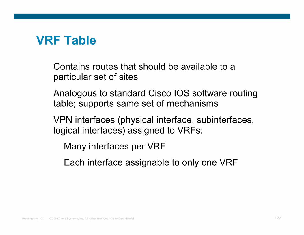
Contains routes that should be available to a particular set of sites
Analogous to standard Cisco IOS software routing table; supports same set of mechanisms
VPN interfaces (physical interface, subinterfaces, logical interfaces) assigned to VRFs:
Many interfaces per VRF
Each interface assignable to only one VRF
Page 123
© 2008 Cisco Systems, Inc. All rights reserved. Cisco Confidential Presentation_ID 123
BGP Route Propagation—Outbound
• Two VPNs are attached to the same PE router. • Each VPN is represented by a VRF.
Page 124
© 2008 Cisco Systems, Inc. All rights reserved. Cisco Confidential Presentation_ID 124
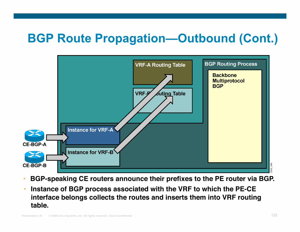
• BGP-speaking CE routers announce their prefixes to the PE router via BGP.
BGP Route Propagation—Outbound (Cont.)
Page 125
© 2008 Cisco Systems, Inc. All rights reserved. Cisco Confidential Presentation_ID 125
• BGP-speaking CE routers announce their prefixes to the PE router via BGP. • Instance of BGP process associated with the VRF to which the PE-CE
interface belongs collects the routes and inserts them into VRF routingtable.
BGP Route Propagation—Outbound (Cont.)
Page 126
© 2008 Cisco Systems, Inc. All rights reserved. Cisco Confidential Presentation_ID 126
• Route distinguisher is prepended during route export to the BGP routes from VRF instance of BGP process to convert them into VPNv4 prefixes. Route targets are attached to these prefixes.
BGP Route Propagation—Outbound (Cont.)
Page 127
© 2008 Cisco Systems, Inc. All rights reserved. Cisco Confidential Presentation_ID 127
• VPNv4 prefixes are propagated to other PE routers.
• Route distinguisher is prepended during route export to the BGP routes from VRF instance of BGP process to convert them into VPNv4 prefixes. Route targets are attached to these prefixes.
BGP Route Propagation—Outbound (Cont.)
Page 128
© 2008 Cisco Systems, Inc. All rights reserved. Cisco Confidential Presentation_ID 128
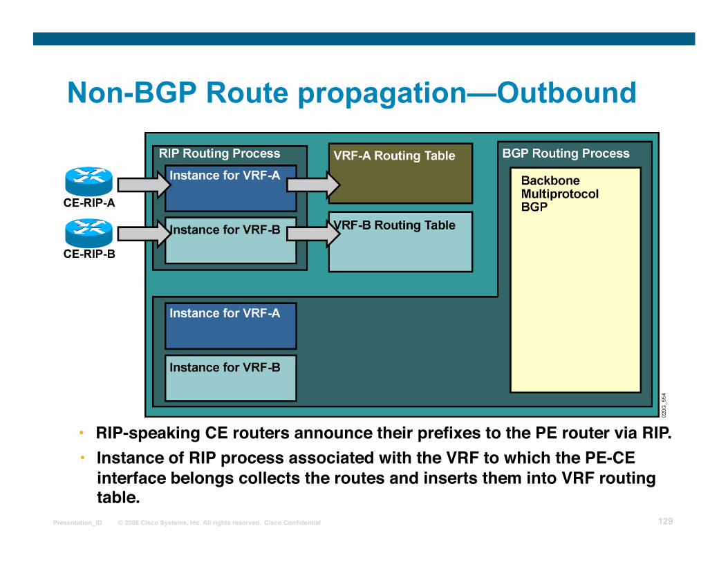
• RIP-speaking CE routers announce their prefixes to the PE router via RIP.
Non-BGP Route propagation - Outbound
Page 129
© 2008 Cisco Systems, Inc. All rights reserved. Cisco Confidential Presentation_ID 129
• RIP-speaking CE routers announce their prefixes to the PE router via RIP.
Non-BGP Route propagation—Outbound
• Instance of RIP process associated with the VRF to which the PE-CEinterface belongs collects the routes and inserts them into VRF routingtable.
Page 130
© 2008 Cisco Systems, Inc. All rights reserved. Cisco Confidential Presentation_ID 130
• RIP routes entered in the VRF routing table are redistributed into BGP for further propagation into the MPLS VPN backbone.
Non-BGP Route propagation—Outbound (Cont.)
Page 131
© 2008 Cisco Systems, Inc. All rights reserved. Cisco Confidential Presentation_ID 131
• Redistribution between RIP and BGP has to be configured for properMPLS VPN operation.
• RIP routes entered in the VRF routing table are redistributed into BGP for further propagation into the MPLS VPN backbone.
Non-BGP Route propagation—Outbound (Cont.)
Page 132
© 2008 Cisco Systems, Inc. All rights reserved. Cisco Confidential Presentation_ID 132
Route Propagation—Inbound
• VPNv4 prefixes are received from other PE routers.
Page 133
© 2008 Cisco Systems, Inc. All rights reserved. Cisco Confidential Presentation_ID 133
Route Propagation—Inbound (Cont.)
• The VPNv4 prefixes are inserted into proper VRF routing tables based on their route targets and import route targets configured in VRFs.
• Route distinguisher is removed during this process.
• VPNv4 prefixes are received from other PE routers.
Page 134
© 2008 Cisco Systems, Inc. All rights reserved. Cisco Confidential Presentation_ID 134
Route Propagation—Inbound (Cont.)
• Routes are received from backbone MP-BGP and imported into a VRF.
Page 135
© 2008 Cisco Systems, Inc. All rights reserved. Cisco Confidential Presentation_ID 135
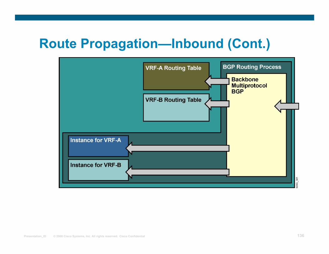
Route Propagation—Inbound (Cont.)
• Routes are received from backbone MP-BGP and imported into a VRF. • IPv4 routes are forwarded to EBGP CE neighbors attached to that VRF.
Page 136
© 2008 Cisco Systems, Inc. All rights reserved. Cisco Confidential Presentation_ID 136
Route Propagation—Inbound (Cont.)
Page 137
© 2008 Cisco Systems, Inc. All rights reserved. Cisco Confidential Presentation_ID 137
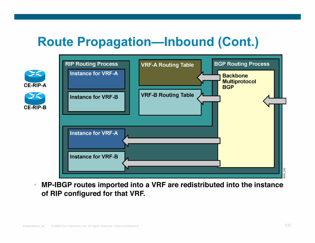
Route Propagation—Inbound (Cont.)
• MP-IBGP routes imported into a VRF are redistributed into the instanceof RIP configured for that VRF.
Page 138
© 2008 Cisco Systems, Inc. All rights reserved. Cisco Confidential Presentation_ID 138
Route Propagation—Inbound (Cont.)
• MP-IBGP routes imported into a VRF are redistributed into the instanceof RIP configured for that VRF.
• Redistribution between BGP and RIP has to be configured for end-to-end RIP routing between CE routers.
Page 139
© 2008 Cisco Systems, Inc. All rights reserved. Cisco Confidential Presentation_ID 139
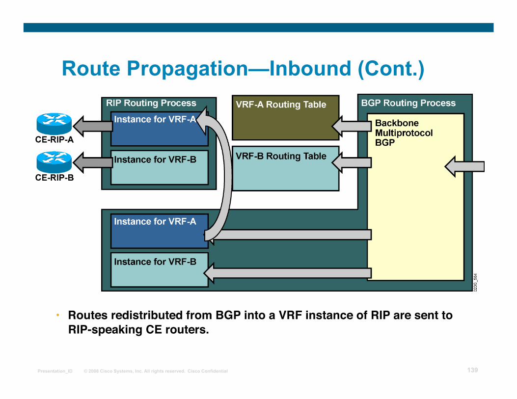
Route Propagation—Inbound (Cont.)
• Routes redistributed from BGP into a VRF instance of RIP are sent toRIP-speaking CE routers.
Page 140
© 2008 Cisco Systems, Inc. All rights reserved. Cisco Confidential Presentation_ID 140
Summary
A VRF is a routing and forwarding instance that you can use for a single VPN site or for many sites connected to the same PE router. Routing contexts were introduced in Cisco IOS software to support the need for separate isolated copies of VPN routing protocols. No limit to the number of interfaces associated with one VRF, but in practice, each interface can be assigned to only one VRF.
Page 141
© 2008 Cisco Systems, Inc. All rights reserved. Cisco Confidential Presentation_ID 141
MPLS workshop
Configuring VRF Tables
Page 142
© 2008 Cisco Systems, Inc. All rights reserved. Cisco Confidential Presentation_ID 142
Outline
Overview
VRF Configuration Tasks
Creating VRF Tables and Assigning RDs
Specifying Export and Import RTs
Assigning an Interface to VRF Table
Sample VPN Network Example
Lesson Summary
Page 143
© 2008 Cisco Systems, Inc. All rights reserved. Cisco Confidential Presentation_ID 143
VRF Configuration Tasks
VRF configuration tasks: Create a VRF table
Assign RD to the VRF
Specify export and import route targets
Assign interfaces to VRFs
Page 144
© 2008 Cisco Systems, Inc. All rights reserved. Cisco Confidential Presentation_ID 144
ip vrf name
Router(config)#
• Creates a new VRF or enters configuration of an existing VRF.
• VRF names are case-sensitive. • VRF is not operational unless you configure RD. • VRF names have only local significance.
Creating VRF Tables and Assigning RDs
rd route-distinguisher
Router(config-vrf)#
• Assigns a route distinguisher to a VRF. • You can use ASN:nn or A.B.C.D:nn format for RD. • Each VRF in a PE router has to have a unique RD.
Page 145
© 2008 Cisco Systems, Inc. All rights reserved. Cisco Confidential Presentation_ID 145
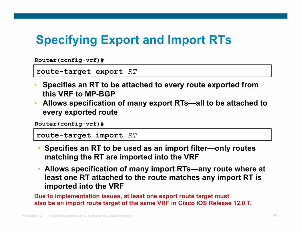
route-target export RT
Router(config-vrf)#
• Specifies an RT to be attached to every route exported from this VRF to MP-BGP
• Allows specification of many export RTs—all to be attached to every exported route
route-target import RT
Router(config-vrf)#
• Specifies an RT to be used as an import filter—only routes matching the RT are imported into the VRF
• Allows specification of many import RTs—any route where at least one RT attached to the route matches any import RT is imported into the VRF
Due to implementation issues, at least one export route target must also be an import route target of the same VRF in Cisco IOS Release 12.0 T.
Specifying Export and Import RTs
Page 146
© 2008 Cisco Systems, Inc. All rights reserved. Cisco Confidential Presentation_ID 146
route-target both RT
Router(config-vrf)#
• In cases where the export RT matches the import RT, use this form of route-target command.
Sample router configuration for simple customer VPN:
Specifying Export and Import RTs (Cont.)
Page 147
© 2008 Cisco Systems, Inc. All rights reserved. Cisco Confidential Presentation_ID 147
ip vrf forwarding vrf-name
Router(config-if)#
• Associates an interface with the specified VRF. • Existing IP address removed from the interface
when interface is put into VRF—IP address must be reconfigured.
• CEF switching must be enabled on the interface.
Sample router configuration:
Assigning an Interface to VRF Table
Page 148
© 2008 Cisco Systems, Inc. All rights reserved. Cisco Confidential Presentation_ID 148
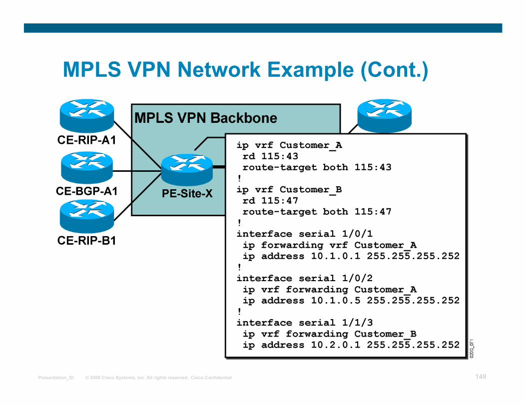
MPLS VPN Network Example
• The network supports two VPN customers. • Customer A runs RIP and BGP with the service
provider; customer B uses only RIP. • Both customers use network 10.0.0.0.
Page 149
© 2008 Cisco Systems, Inc. All rights reserved. Cisco Confidential Presentation_ID 149
MPLS VPN Network Example (Cont.)
Page 150
© 2008 Cisco Systems, Inc. All rights reserved. Cisco Confidential Presentation_ID 150
Summary
A unique RD must be assigned to every VRF created in a PE router.
The same RD could be used on all PEs for simple VPN service.
For simple VPN service, import and export RT values should be the same.
Two formats for RD and RT are as follows:
ASN:nn
A.B.C.D:nn
Page 151
© 2008 Cisco Systems, Inc. All rights reserved. Cisco Confidential Presentation_ID 151
MPLS workshop
Configuring an MP-BGP Session Between PE routers
Page 152
© 2008 Cisco Systems, Inc. All rights reserved. Cisco Confidential Presentation_ID 152
Outline
Overview
Configuring BGP Address families
BGP Neighbors
Configuring MP-BGP
Configuring MP-IBGP
MP-BGP BGP Community Propagation
Disabling IPv4 Route Exchange
Verifying Configurations
Lesson Summary
Page 153
© 2008 Cisco Systems, Inc. All rights reserved. Cisco Confidential Presentation_ID 153
Configuring BGP Address Families
The BGP process in an MPLS VPN-enabled router performs three separate tasks:
Global BGP routes (Internet routing) are exchanged as in traditional BGP setup.
VPNv4 prefixes are exchanged through MP-BGP.
VPN routes are exchanged with CE routers through per-VRF EBGP sessions.
Address families (routing protocol contexts) are used to configure these three tasks in the same BGP process.
Page 154
© 2008 Cisco Systems, Inc. All rights reserved. Cisco Confidential Presentation_ID 154
router bgp as-number Router(config)#
• Selects global BGP routing process
address-family vpnv4 Router(config-router)#
• Selects configuration of VPNv4 prefix exchanges under MP-BGP sessions
address-family ipv4 vrf vrf-name Router(config-router)#
• Selects configuration of per-VRF PE-CE EBGP parameters
Configuring BGP Address Families (Cont.)
Page 155
© 2008 Cisco Systems, Inc. All rights reserved. Cisco Confidential Presentation_ID 155
BGP Neighbors
MP-BGP neighbors are configured under the BGP routing process:
These neighbors need to be activated for each global address family that they support.
Per-address-family parameters can be configured for these neighbors.
VRF-specific EBGP neighbors are configured under corresponding address families.
Page 156
© 2008 Cisco Systems, Inc. All rights reserved. Cisco Confidential Presentation_ID 156
Configuring MP-BGP
MPLS VPN MP-BGP configuration steps: Configure MP-BGP neighbor under BGP routing process.
Configure BGP address family VPNv4.
Activate configured BGP neighbor for VPNv4 route exchange.
Specify additional parameters for VPNv4 route exchange (filters, next hops, and so on).
Page 157
© 2008 Cisco Systems, Inc. All rights reserved. Cisco Confidential Presentation_ID 157
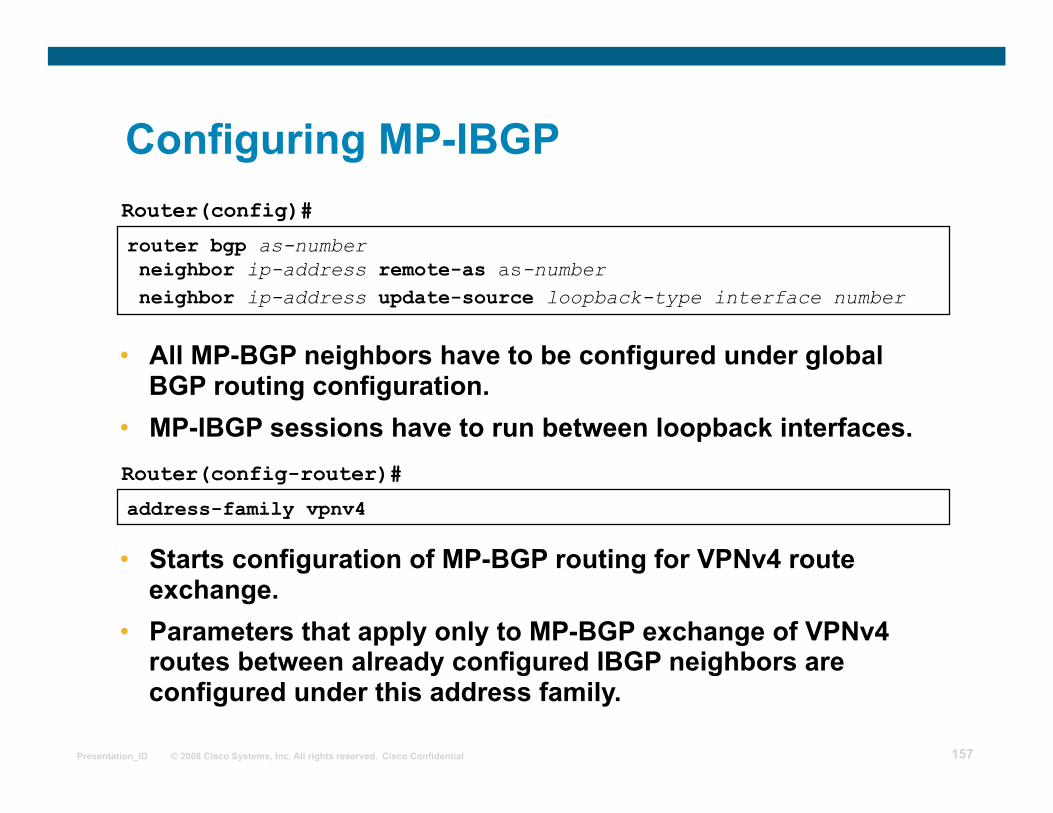
router bgp as-number neighbor ip-address remote-as as-number neighbor ip-address update-source loopback-type interface number
Router(config)#
• All MP-BGP neighbors have to be configured under global BGP routing configuration.
• MP-IBGP sessions have to run between loopback interfaces.
address-family vpnv4
Router(config-router)#
• Starts configuration of MP-BGP routing for VPNv4 route exchange.
• Parameters that apply only to MP-BGP exchange of VPNv4 routes between already configured IBGP neighbors are configured under this address family.
Configuring MP-IBGP
Page 158
© 2008 Cisco Systems, Inc. All rights reserved. Cisco Confidential Presentation_ID 158
neighbor ip-address activate
Router(config-router-af)#
• The BGP neighbor defined under BGP router configuration has to be activated for VPNv4 route exchange.
neighbor ip-address next-hop-self
Router(config-router-af)#
• The next-hop-self keyword can be configured on the MP-IBGP session. With current IOS, this is enabled by default
Configuring MP-IBGP (Cont.)
Page 159
© 2008 Cisco Systems, Inc. All rights reserved. Cisco Confidential Presentation_ID 159
neighbor ip-address send-community [extended | both]
Router(config-router-af)#
• This command configures propagation of standard and extended BGP communities attached to VPNv4 prefixes.
• Default value: only extended communities are sent.
• Usage guidelines: – Extended BGP communities attached to VPNv4 prefixes
have to be exchanged between MP-BGP neighbors for proper MPLS VPN operation.
– To propagate standard BGP communities between MP-BGP neighbors, use the both option.
MP-BGP BGP Community Propagation
Page 160
© 2008 Cisco Systems, Inc. All rights reserved. Cisco Confidential Presentation_ID 160
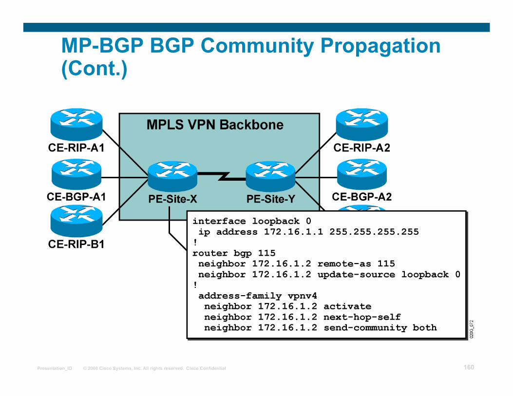
MP-BGP BGP Community Propagation (Cont.)
Page 161
© 2008 Cisco Systems, Inc. All rights reserved. Cisco Confidential Presentation_ID 161
no bgp default ipv4 unicast
Router(config-router)#
• Exchange of IPv4 routes between BGP neighbors is enabled by default—every configured neighbor will also receive IPv4 routes.
• This command disables default exchange of IPv4 routes—neighbors that need to receive IPv4 routes have to be activated for IPv4 route exchange.
• Use this command when the same router carries Internet and VPNv4 routes and you do not want to propagate Internet routes to some PE neighbors.
Disabling IPv4 Route Exchange
Page 162
© 2008 Cisco Systems, Inc. All rights reserved. Cisco Confidential Presentation_ID 162
Disabling IPv4 Route Exchange (Cont.)
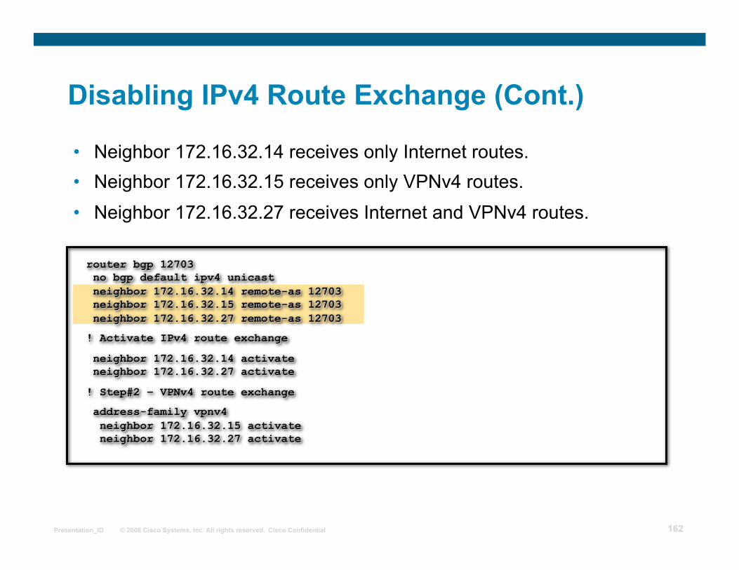
• Neighbor 172.16.32.14 receives only Internet routes. • Neighbor 172.16.32.15 receives only VPNv4 routes. • Neighbor 172.16.32.27 receives Internet and VPNv4 routes.
Page 163
© 2008 Cisco Systems, Inc. All rights reserved. Cisco Confidential Presentation_ID 163
MPLS/VPN Monitoring Commands
telnet host /vrf name router#
• Performs PE - CE telnet through specified VRF
ping vrf name …
trace vrf name …
router#
• Performs ping based on VRF routing table
• Performs VRF-based traceroute
router#
Page 164
© 2008 Cisco Systems, Inc. All rights reserved. Cisco Confidential Presentation_ID 164
show ip vrf
Router#show ip vrf
Name Default RD Interfaces
SiteA2 103:10 Serial1/1.1
SiteB 103:20 Serial1/1.2
SiteX 103:30 Ethernet0/0
Page 165
© 2008 Cisco Systems, Inc. All rights reserved. Cisco Confidential Presentation_ID 165
show ip vrf interfaces
Router#show ip vrf interfaces
Interface IP-Address VRF Protocol
Serial1/1.1 150.1.31.37 SiteA2 up
Serial1/1.2 150.1.32.33 SiteB up
Ethernet0/0 192.168.22.3 SiteX up
Page 166
© 2008 Cisco Systems, Inc. All rights reserved. Cisco Confidential Presentation_ID 166
Monitoring VRF Routing
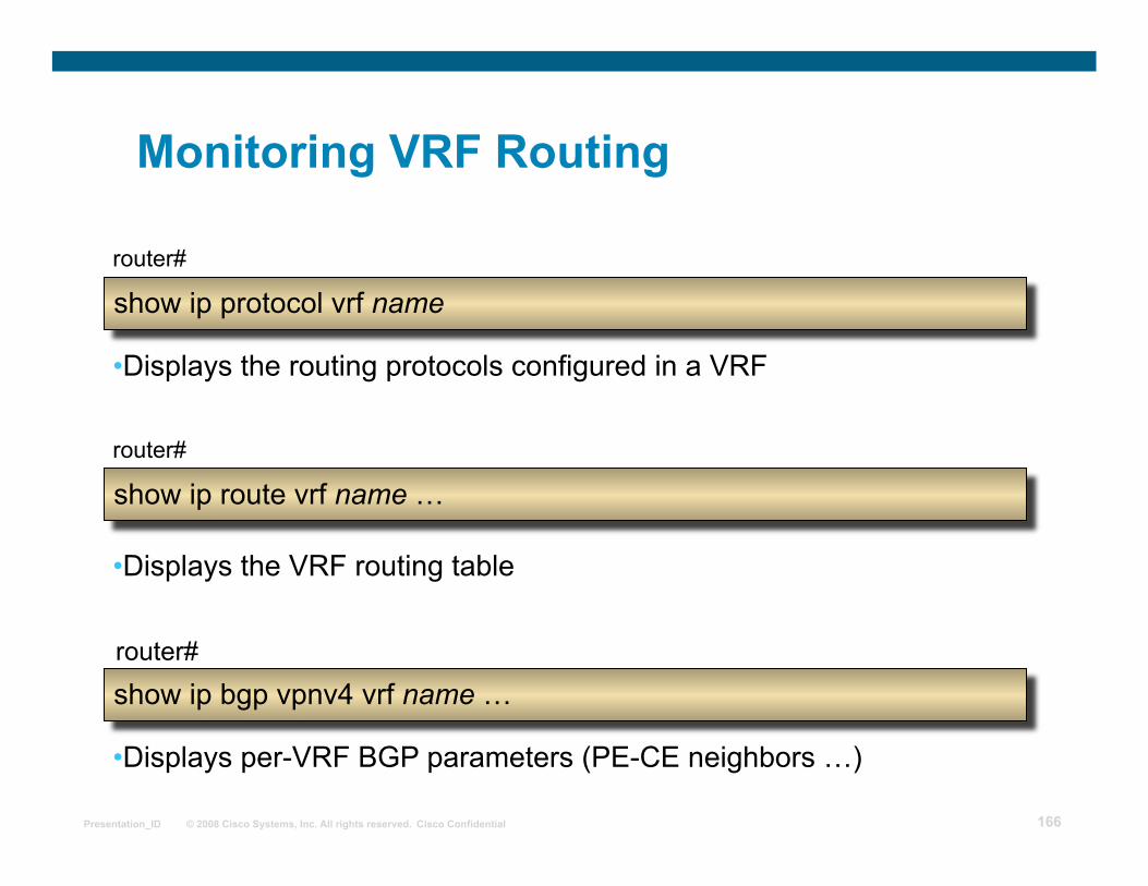
show ip protocol vrf name router#
• Displays the routing protocols configured in a VRF
show ip route vrf name …
show ip bgp vpnv4 vrf name …
router#
• Displays the VRF routing table
• Displays per-VRF BGP parameters (PE-CE neighbors …)
router#
Page 167
© 2008 Cisco Systems, Inc. All rights reserved. Cisco Confidential Presentation_ID 167
show ip protocol vrf
Router#show ip protocol vrf SiteX
Routing Protocol is "rip"
Sending updates every 30 seconds, next due in 10 seconds
Invalid after 180 seconds, hold down 180, flushed after 240
Outgoing update filter list for all interfaces is
Incoming update filter list for all interfaces is
Redistributing: rip, bgp 3
Default version control: send version 2, receive version 2
Interface Send Recv Triggered RIP Key-chain
Ethernet0/0 2 2
Routing for Networks:
192.168.22.0
Routing Information Sources:
Gateway Distance Last Update
Distance: (default is 120)
Page 168
© 2008 Cisco Systems, Inc. All rights reserved. Cisco Confidential Presentation_ID 168
show ip route vrf Router#show ip route vrf SiteA2
Codes: C - connected,S -static,I -IGRP,R -RIP,M -mobile,B -BGP
D - EIGRP, EX - EIGRP external,O -OSPF,IA -OSPF interarea
N1 - OSPF NSSA external type 1, N2 - OSPF NSSA external type 2
E1 - OSPF external type 1, E2 - OSPF external type 2, E - EGP
i - IS-IS, L1 - IS-IS level-1, L2 - IS-IS level-2,
* - candidate default, U - per-user static route,o -ODR
P - periodic downloaded static route
Gateway of last resort is not set
O 203.1.20.0/24 [110/782] via 150.1.31.38, 02:52:13, Serial1/1.1
203.1.2.0/32 is subnetted, 1 subnets
O 203.1.2.1 [110/782] via 150.1.31.38, 02:52:13, Serial1/1.1
203.1.1.0/32 is subnetted, 1 subnets
B 203.1.1.1 [200/1] via 192.168.3.103, 01:14:32
B 203.1.135.0/24 [200/782] via 192.168.3.101, 02:05:38
B 203.1.134.0/24 [200/1] via 192.168.3.101, 02:05:38
B 203.1.10.0/24 [200/1] via 192.168.3.103, 01:14:32
… rest deleted …
Page 169
© 2008 Cisco Systems, Inc. All rights reserved. Cisco Confidential Presentation_ID 169
show ip bgp vpnv4 vrf neighbor
Page 170
© 2008 Cisco Systems, Inc. All rights reserved. Cisco Confidential Presentation_ID 170
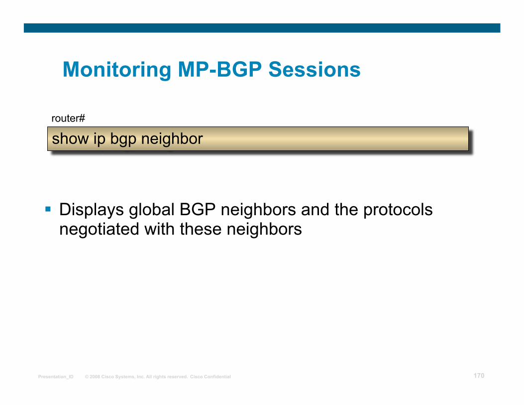
Monitoring MP-BGP Sessions
Displays global BGP neighbors and the protocols negotiated with these neighbors
show ip bgp neighbor router#
Page 171
© 2008 Cisco Systems, Inc. All rights reserved. Cisco Confidential Presentation_ID 171
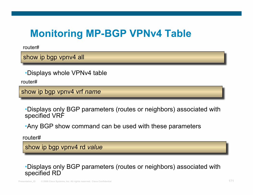
Monitoring MP-BGP VPNv4 Table
show ip bgp vpnv4 all router#
• Displays whole VPNv4 table
show ip bgp vpnv4 vrf name
show ip bgp vpnv4 rd value
router#
• Displays only BGP parameters (routes or neighbors) associated with specified VRF • Any BGP show command can be used with these parameters
• Displays only BGP parameters (routes or neighbors) associated with specified RD
router#
Page 172
© 2008 Cisco Systems, Inc. All rights reserved. Cisco Confidential Presentation_ID 172
Monitoring per-VRF CEF and LFIB Structures
show ip cef vrf name router#
• Displays per-VRF CEF table
show ip cef vrf name prefix detail
show tag-switching forwarding vrf name
router#
• Displays details of individual CEF entry, including label stack
• Displays labels allocated by MPLS/VPN for routes in specified vrf
router#
Page 173
© 2008 Cisco Systems, Inc. All rights reserved. Cisco Confidential Presentation_ID 173
Summary
MPLS VPN architecture uses the BGP routing protocol in two ways:
VPNv4 routes are propagated across an MPLS VPN backbone using MP-BGP between the PE routers.
BGP can be used as the PE-CE routing protocol to exchange VPN routes between the PE routers and the customer edge (CE) routers.
Only one BGP process can be configured per router.
Routing protocol contexts are used to configure independent route exchange mechanisms.
Page 174
© 2008 Cisco Systems, Inc. All rights reserved. Cisco Confidential Presentation_ID 174
MPLS workshop
Configuring Static routes and BGP as PE-CE routing protocol
Page 175
© 2008 Cisco Systems, Inc. All rights reserved. Cisco Confidential Presentation_ID 175
Outline Static Route as PE-CE Protocol
Benefits of BGP as PE-CE protocol
Configuring per-VRF BGP Routing Context
Limiting the Number of Routes in a VRF
Limiting the Number of Prefixes Received from a BGP Neighbor
AS-Override
Hub and Spoke setup in MPLS VPNs
AllowAS-in
Implementing Site of Origin (SOO) for loop prevention
Selective Import
Selective Export
Lesson Summary
Page 176
© 2008 Cisco Systems, Inc. All rights reserved. Cisco Confidential Presentation_ID 176
Configuring Per-VRF Static Routes
ip route vrf name static route parameters
router(config)#
• This command configures per-VRF static routes • The route is entered in the specified Virtual Routing Table • You always have to specify outgoing interface, even if you specify the next-hop
ip route vrf Customer_ABC 10.0.0.0 255.0.0.0 10.250.0.2
serial 0/0
!
router bgp 12703
address-family ipv4 vrf Customer_ABC
redistribute static
Sample router configuration:
Page 177
© 2008 Cisco Systems, Inc. All rights reserved. Cisco Confidential Presentation_ID 177
Benefits of using BGP as PE-CE protocol
• BGP allows continuity of policies between sites
• Use of private AS numbers for VPN sites allows easier configuration and saves AS numbers
• No redistribution involved
• Standard Communities for routing policies between sites
• Route-map and filters based on BGP attributes
• BGP sessions can be authenticated
• PE can limit the total number of prefixes the CE is allowed to announce -– Avoids impact of CE mis-configuration
Page 178
© 2008 Cisco Systems, Inc. All rights reserved. Cisco Confidential Presentation_ID 178
router bgp as-number address-family ipv4 vrf vrf-name ... Per-VRF BGP definitions ...
Router(config)#
• There is only one BGP process per router • Per-VRF parameters are specified in routing contexts, which
are selected with the address family command • Select per-VRF BGP context with the address-family command. • Configure CE eBGP neighbors in VRF context, not in the
global BGP configuration. • CE neighbors have to be activated with the neighbor activate
command.
Configuring Per-VRF BGP Routing Context
Page 179
© 2008 Cisco Systems, Inc. All rights reserved. Cisco Confidential Presentation_ID 179
Configuring Per-VRF BGP Routing Context (Cont.)
Page 180
© 2008 Cisco Systems, Inc. All rights reserved. Cisco Confidential Presentation_ID 180
Limiting the Number of Routes in a VRF
Service providers offering MPLS VPN services are at risk of denial-of-service attacks similar to those aimed at ISPs offering BGP connectivity:
Any customer can generate any number of routes, using resources in the PE routers.
Therefore, resources used by a single customer have to be limited.
Cisco IOS software offers two solutions:
1. It can limit the number of routes received from a BGP neighbor.
2. It can limit the total number of routes in a VRF.
Page 181
© 2008 Cisco Systems, Inc. All rights reserved. Cisco Confidential Presentation_ID 181
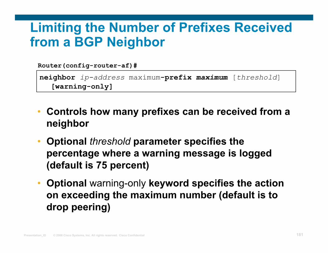
neighbor ip-address maximum-prefix maximum [threshold] [warning-only]
Router(config-router-af)#
• Controls how many prefixes can be received from a neighbor
• Optional threshold parameter specifies the percentage where a warning message is logged (default is 75 percent)
• Optional warning-only keyword specifies the action on exceeding the maximum number (default is to drop peering)
Limiting the Number of Prefixes Received from a BGP Neighbor
Page 182
© 2008 Cisco Systems, Inc. All rights reserved. Cisco Confidential Presentation_ID 182
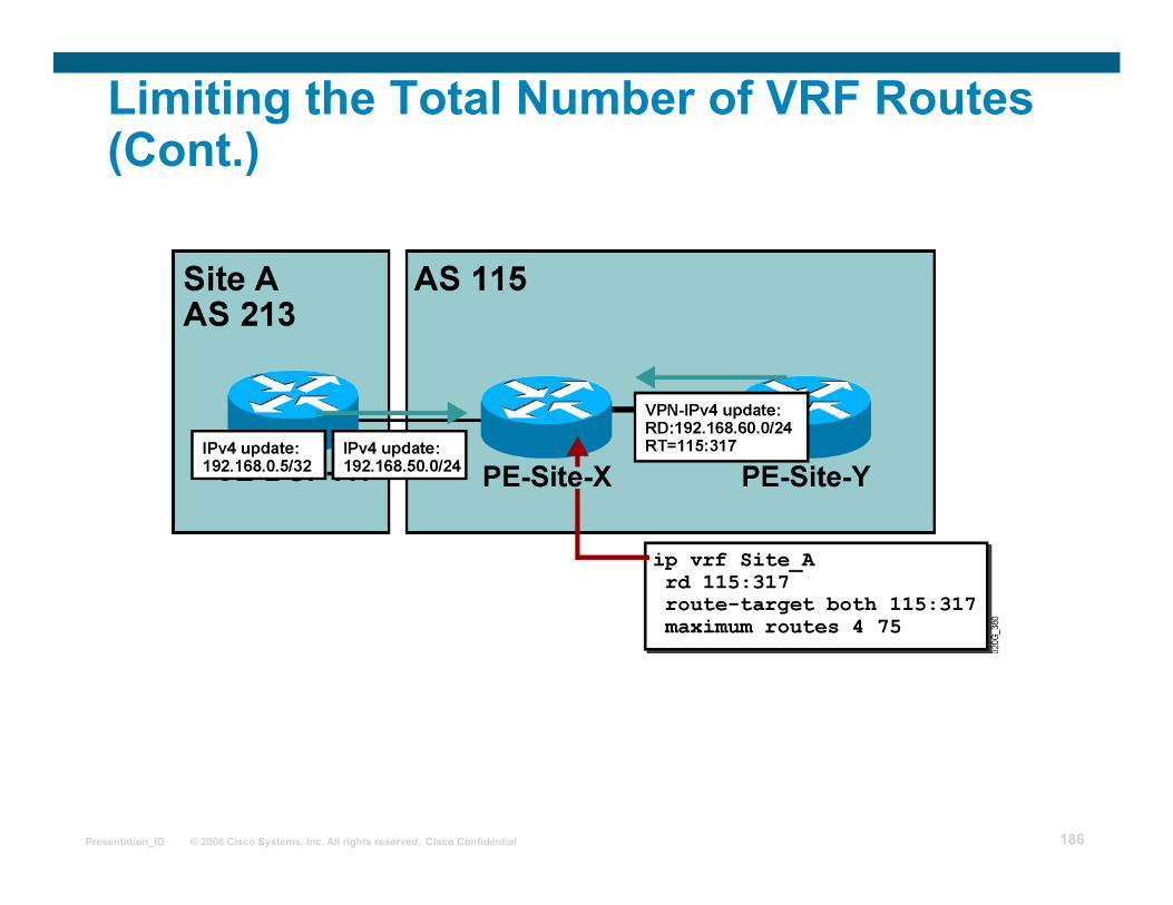
Limiting the Total Number of VRF Routes
The VRF route limit command limits the number of routes that are imported into a VRF:
Routes coming from CE routers
Routes coming from other PEs (imported routes)
The route limit is configured for each VRF.
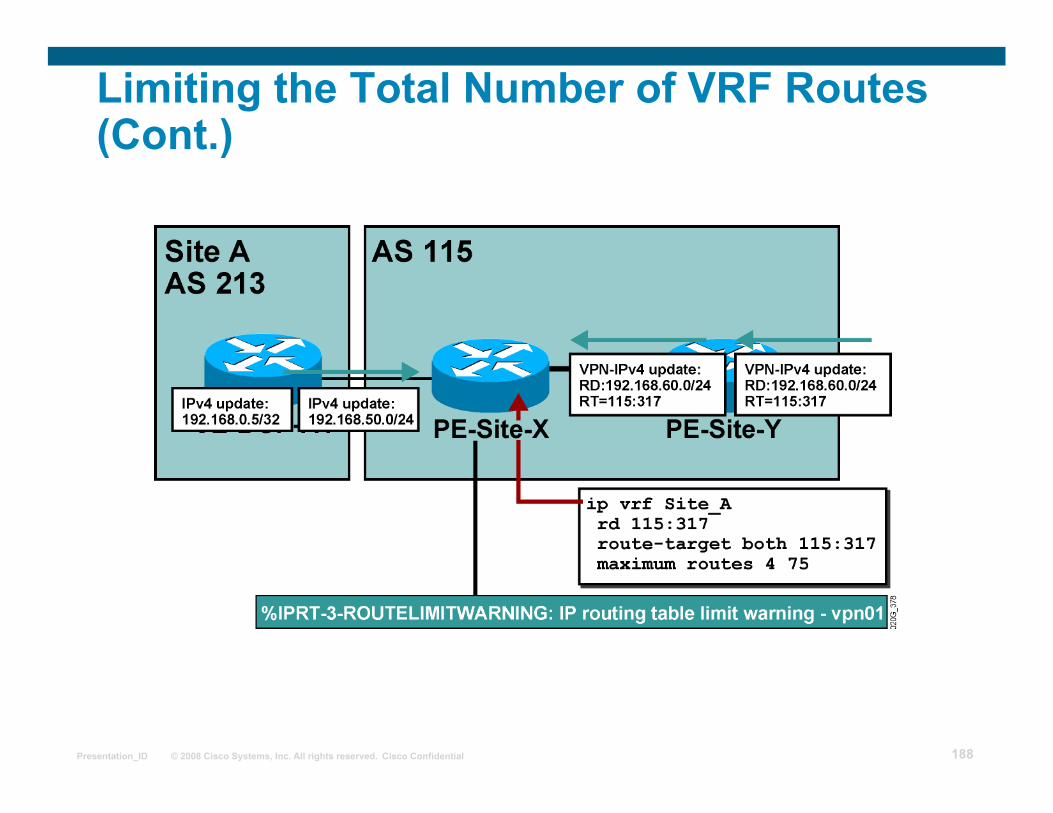
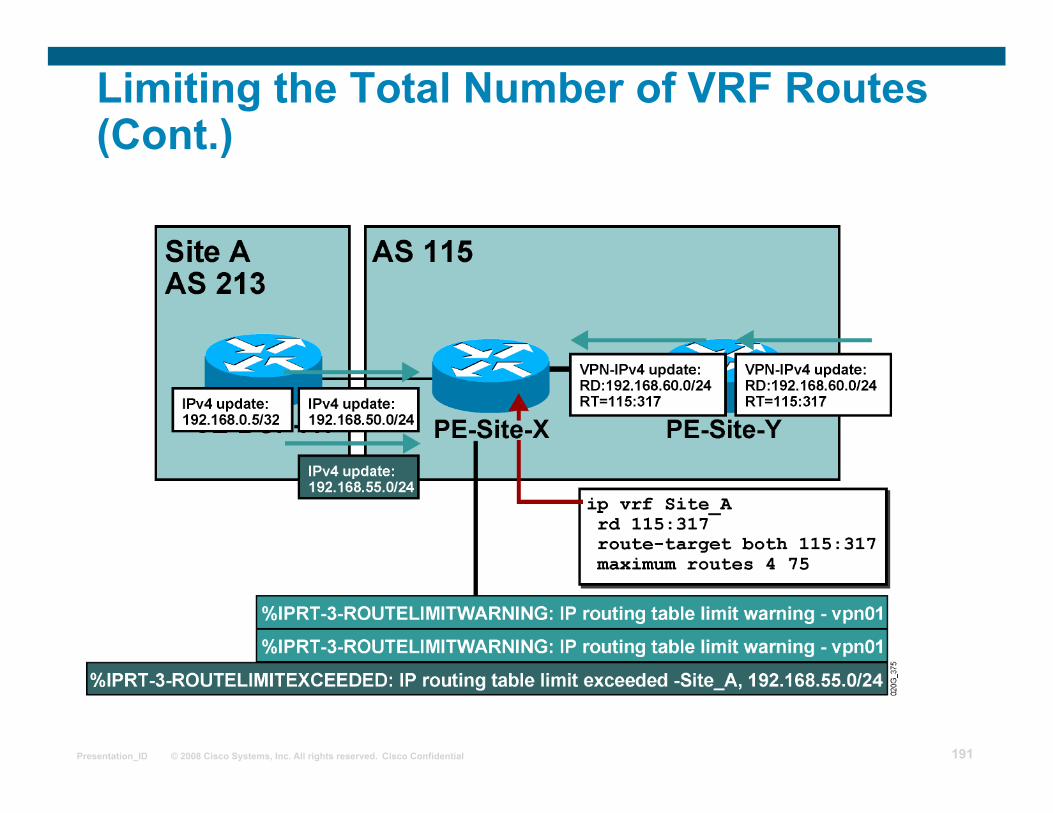
If the number of routes exceeds the route limit: Syslog message is generated.
The Cisco IOS software can be configured to reject routes (optional).
Page 183
© 2008 Cisco Systems, Inc. All rights reserved. Cisco Confidential Presentation_ID 183
maximum routes limit {warn threshold | warn-only}
Router(config-vrf)#
Limiting the Total Number of VRF Routes (Cont.)
This command configures the maximum number of routes accepted into a VRF:
limit is the route limit for the VRF.
warn threshold is the percentage value over which a warning message is sent to syslog.
With warn-only the PE continues accepting routes after the configured limit.
Syslog messages generated by this command are rate-limited.
Page 184
© 2008 Cisco Systems, Inc. All rights reserved. Cisco Confidential Presentation_ID 184
Limiting the Total Number of VRF Routes (Cont.)
Page 185
© 2008 Cisco Systems, Inc. All rights reserved. Cisco Confidential Presentation_ID 185
Limiting the Total Number of VRF Routes (Cont.)
Page 186
© 2008 Cisco Systems, Inc. All rights reserved. Cisco Confidential Presentation_ID 186
Limiting the Total Number of VRF Routes (Cont.)
Page 187
© 2008 Cisco Systems, Inc. All rights reserved. Cisco Confidential Presentation_ID 187
Limiting the Total Number of VRF Routes (Cont.)
Page 188
© 2008 Cisco Systems, Inc. All rights reserved. Cisco Confidential Presentation_ID 188
Limiting the Total Number of VRF Routes (Cont.)
Page 189
© 2008 Cisco Systems, Inc. All rights reserved. Cisco Confidential Presentation_ID 189
Limiting the Total Number of VRF Routes (Cont.)
Page 190
© 2008 Cisco Systems, Inc. All rights reserved. Cisco Confidential Presentation_ID 190
Limiting the Total Number of VRF Routes (Cont.)
Page 191
© 2008 Cisco Systems, Inc. All rights reserved. Cisco Confidential Presentation_ID 191
Limiting the Total Number of VRF Routes (Cont.)
Page 192
© 2008 Cisco Systems, Inc. All rights reserved. Cisco Confidential Presentation_ID 192
AS-override The Issue
The customer wants to reuse the same AS number on several sites:
Page 193
© 2008 Cisco Systems, Inc. All rights reserved. Cisco Confidential Presentation_ID 193
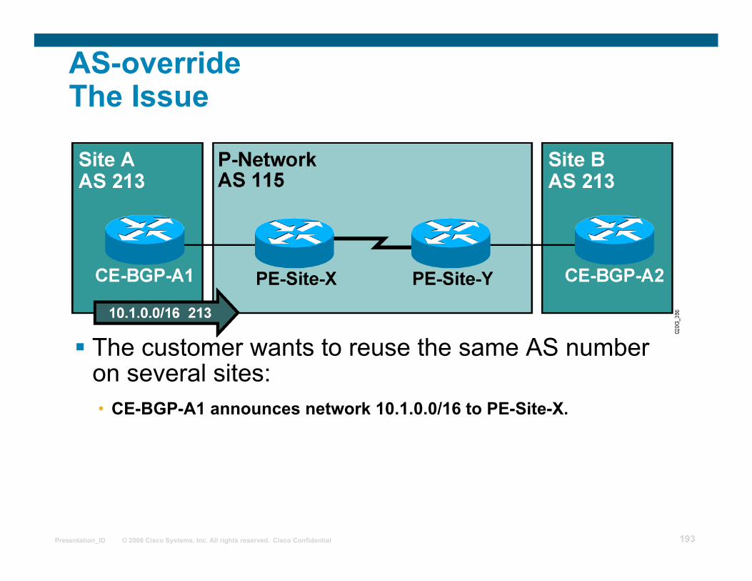
AS-override The Issue
The customer wants to reuse the same AS number on several sites: • CE-BGP-A1 announces network 10.1.0.0/16 to PE-Site-X.
Page 194
© 2008 Cisco Systems, Inc. All rights reserved. Cisco Confidential Presentation_ID 194
AS-override The Issue
The customer wants to reuse the same AS number on several sites: • CE-BGP-A1 announces network 10.1.0.0/16 to PE-Site-X. • The prefix announced by CE-BGP-A1 is propagated to PE-Site-Y
as an internal route through MP-BGP.
Page 195
© 2008 Cisco Systems, Inc. All rights reserved. Cisco Confidential Presentation_ID 195
AS-override The Issue
The customer wants to reuse the same AS number on several sites: • CE-BGP-A1 announces network 10.1.0.0/16 to PE-Site-X. • The prefix announced by CE-BGP-A1 is propagated to PE-Site-Y
as an internal route through MP-BGP. • PE-Site-Y prepends AS 115 to the AS path and propagates the prefix
to CE-BGP-A2.
Page 196
© 2008 Cisco Systems, Inc. All rights reserved. Cisco Confidential Presentation_ID 196
AS-override The Issue
The customer wants to reuse the same AS number on several sites: • CE-BGP-A1 announces network 10.1.0.0/16 to PE-Site-X. • The prefix announced by CE-BGP-A1 is propagated to PE-Site-Y
as an internal route through MP-BGP. • PE-Site-Y prepends AS 115 to the AS path and propagates the prefix
to CE-BGP-A2. • CE-BGP-A2 drops the update because AS 213 is already in the AS path.
Page 197
© 2008 Cisco Systems, Inc. All rights reserved. Cisco Confidential Presentation_ID 197
AS-override (Cont.)
New AS path update procedures have been implemented in order to reuse the same AS number on all VPN sites.
The procedures allow the use of private as well as public AS numbers.
The same AS number may be used for all sites.
Page 198
© 2008 Cisco Systems, Inc. All rights reserved. Cisco Confidential Presentation_ID 198
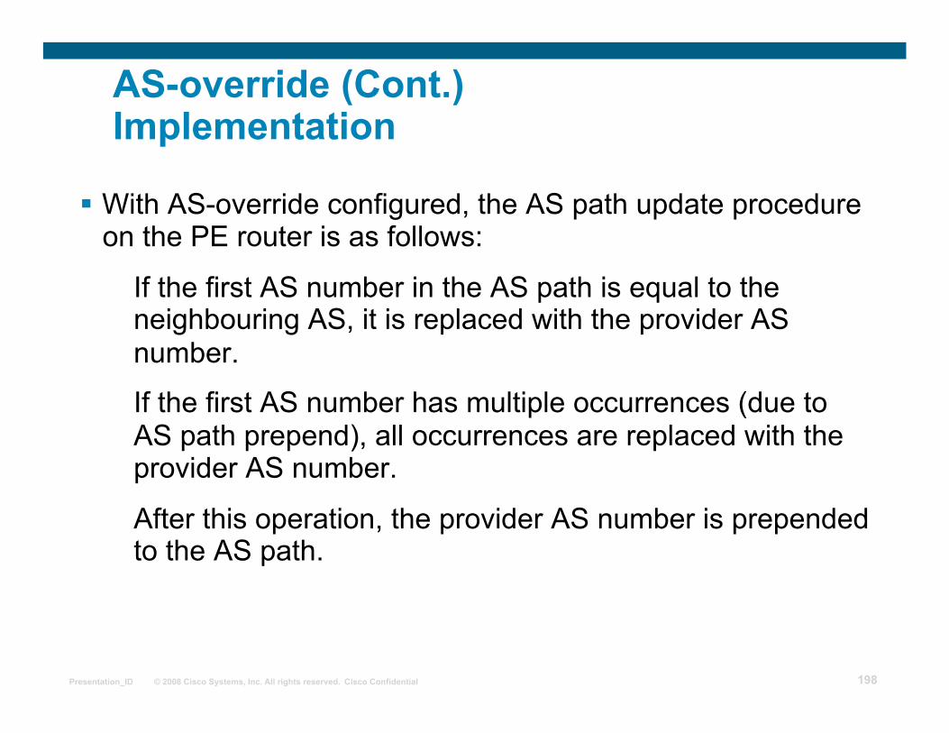
AS-override (Cont.) Implementation
With AS-override configured, the AS path update procedure on the PE router is as follows:
If the first AS number in the AS path is equal to the neighbouring AS, it is replaced with the provider AS number.
If the first AS number has multiple occurrences (due to AS path prepend), all occurrences are replaced with the provider AS number.
After this operation, the provider AS number is prepended to the AS path.
Page 199
© 2008 Cisco Systems, Inc. All rights reserved. Cisco Confidential Presentation_ID 199
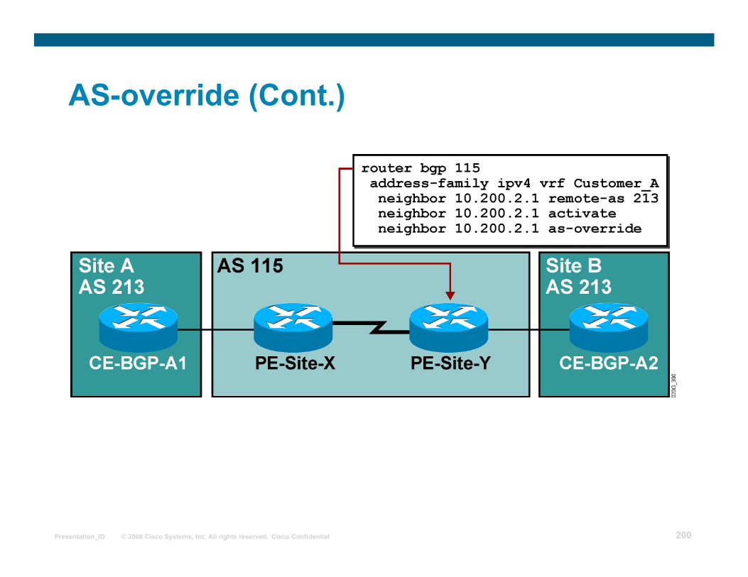
neighbor ip-address as-override
Router(config-router-af)#
• Configured on the PE router as an outbound feature
• This command configures the AS-override AS path update procedure for the specified neighbor.
• AS-override is configured for CE EBGP neighbors in the VRF address family of the BGP process.
AS-override (Cont.)
Page 200
© 2008 Cisco Systems, Inc. All rights reserved. Cisco Confidential Presentation_ID 200
AS-override (Cont.)
Page 201
© 2008 Cisco Systems, Inc. All rights reserved. Cisco Confidential Presentation_ID 201
AS-override (Cont.)
Page 202
© 2008 Cisco Systems, Inc. All rights reserved. Cisco Confidential Presentation_ID 202
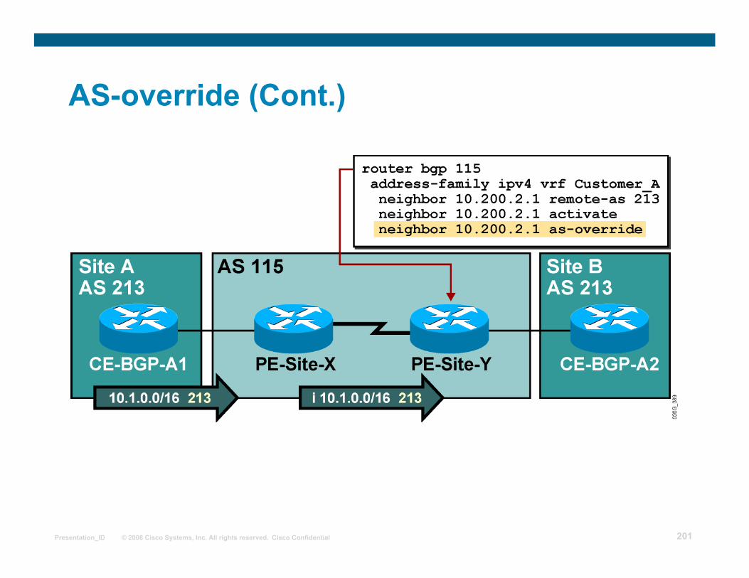
AS-override (Cont.)
• PE-Site-Y replaces AS 213 with AS 115 in the AS path, prepends another copy of AS115 to the AS path, and propagates the prefix.
Page 203
© 2008 Cisco Systems, Inc. All rights reserved. Cisco Confidential Presentation_ID 203
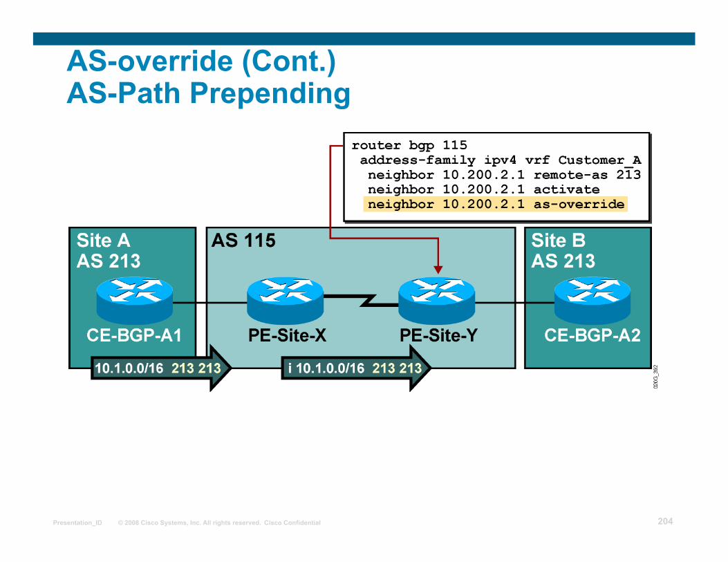
AS-override (Cont.) AS-Path Prepending
Page 204
© 2008 Cisco Systems, Inc. All rights reserved. Cisco Confidential Presentation_ID 204
AS-override (Cont.) AS-Path Prepending
Page 205
© 2008 Cisco Systems, Inc. All rights reserved. Cisco Confidential Presentation_ID 205
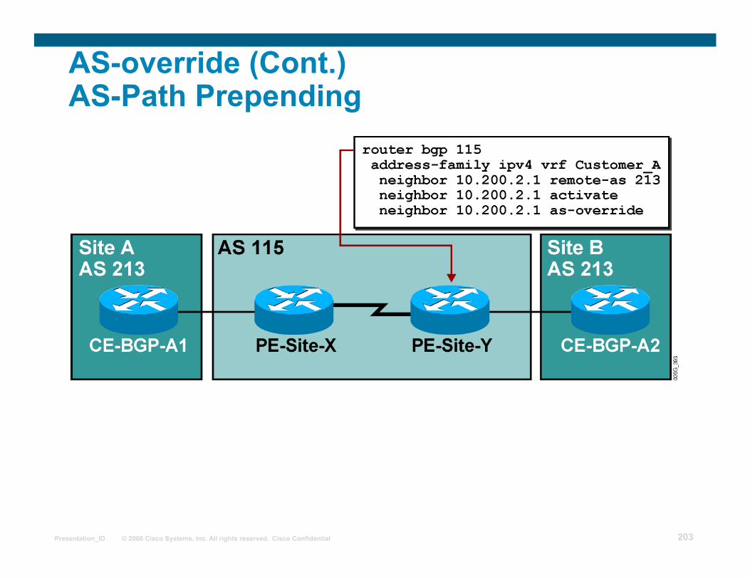
• PE-Site-Y replaces all occurrences of AS 213 with AS 115 in the AS path, prepends another copy of AS 115 to the AS path, and propagates the prefix.
AS-override (Cont.) AS-Path Prepending
Page 206
© 2008 Cisco Systems, Inc. All rights reserved. Cisco Confidential Presentation_ID 206
Hub & Spoke VPN Topology
One central site has full routing knowledge of all other sites of the same VPN
Hub-Site
Other sites will send traffic to the Hub-Site for any destination
Spoke-Sites
The Hub-Site is the central transit point between Spoke-Sites
Security services (filters) Traffic logging and/or accounting Intrusion Detection systems
Page 207
© 2008 Cisco Systems, Inc. All rights reserved. Cisco Confidential Presentation_ID 207
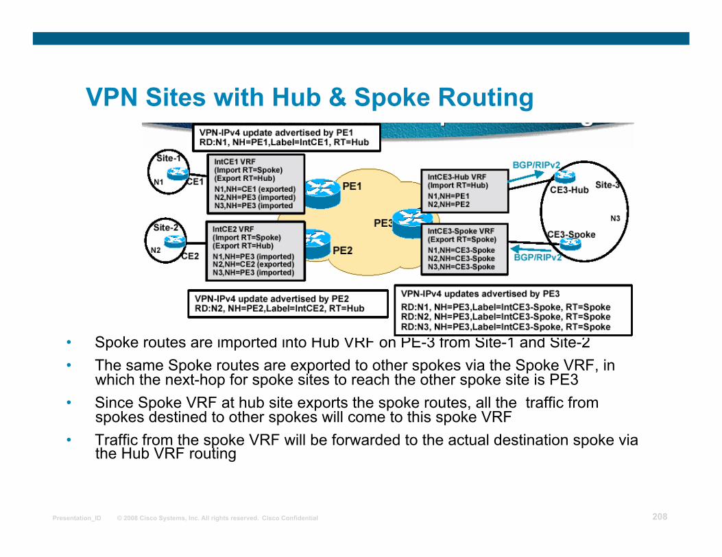
MPLS VPN Topologies VPN Sites with Hub & Spoke Routing
• We need 2 interfaces and 2 unique VRFs on the Hub site. If not, traffic from spokes may just touch PE3 and be forwarded to the spoke site without being processed at the hub site
• Traffic into hub comes in via one VRF (which exports routes, e.g. Spoke vrf) interface and goes out via the other (which imports routes, e.g. Hub vrf).
Page 208
© 2008 Cisco Systems, Inc. All rights reserved. Cisco Confidential Presentation_ID 208
MPLS VPN Topologies VPN Sites with Hub & Spoke Routing
• Spoke routes are imported into Hub VRF on PE-3 from Site-1 and Site-2 • The same Spoke routes are exported to other spokes via the Spoke VRF, in
which the next-hop for spoke sites to reach the other spoke site is PE3 • Since Spoke VRF at hub site exports the spoke routes, all the traffic from
spokes destined to other spokes will come to this spoke VRF • Traffic from the spoke VRF will be forwarded to the actual destination spoke via
the Hub VRF routing
Page 209
© 2008 Cisco Systems, Inc. All rights reserved. Cisco Confidential Presentation_ID 209
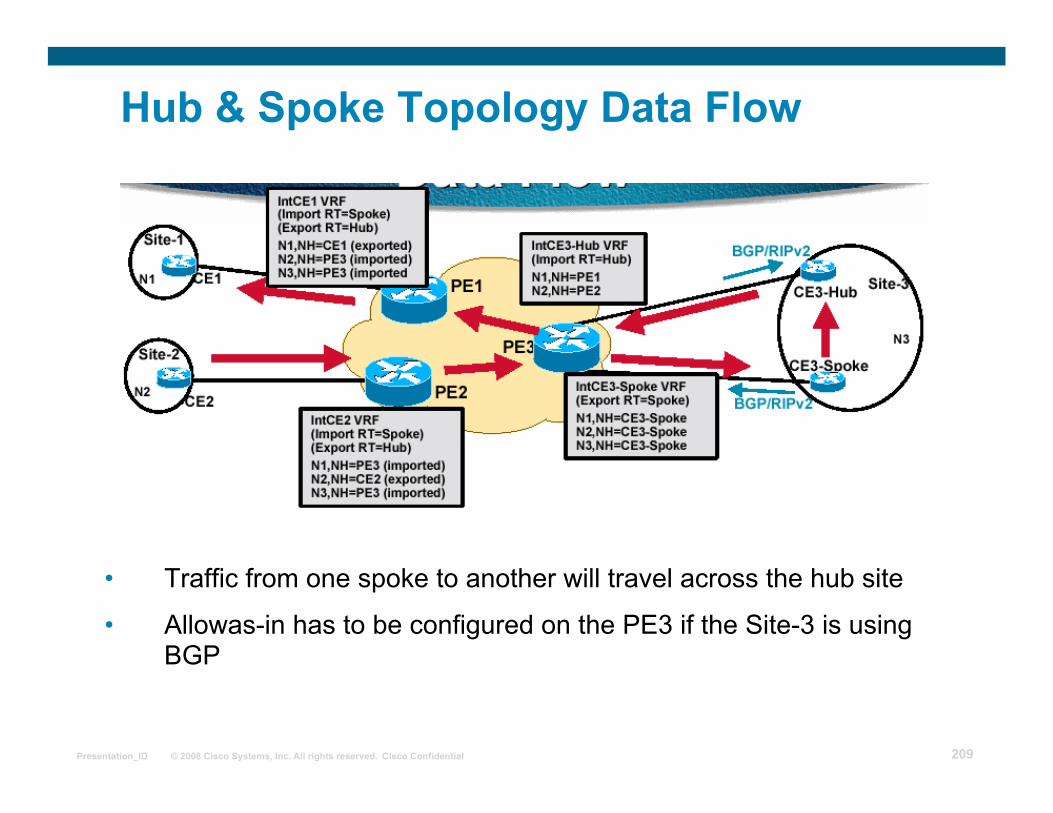
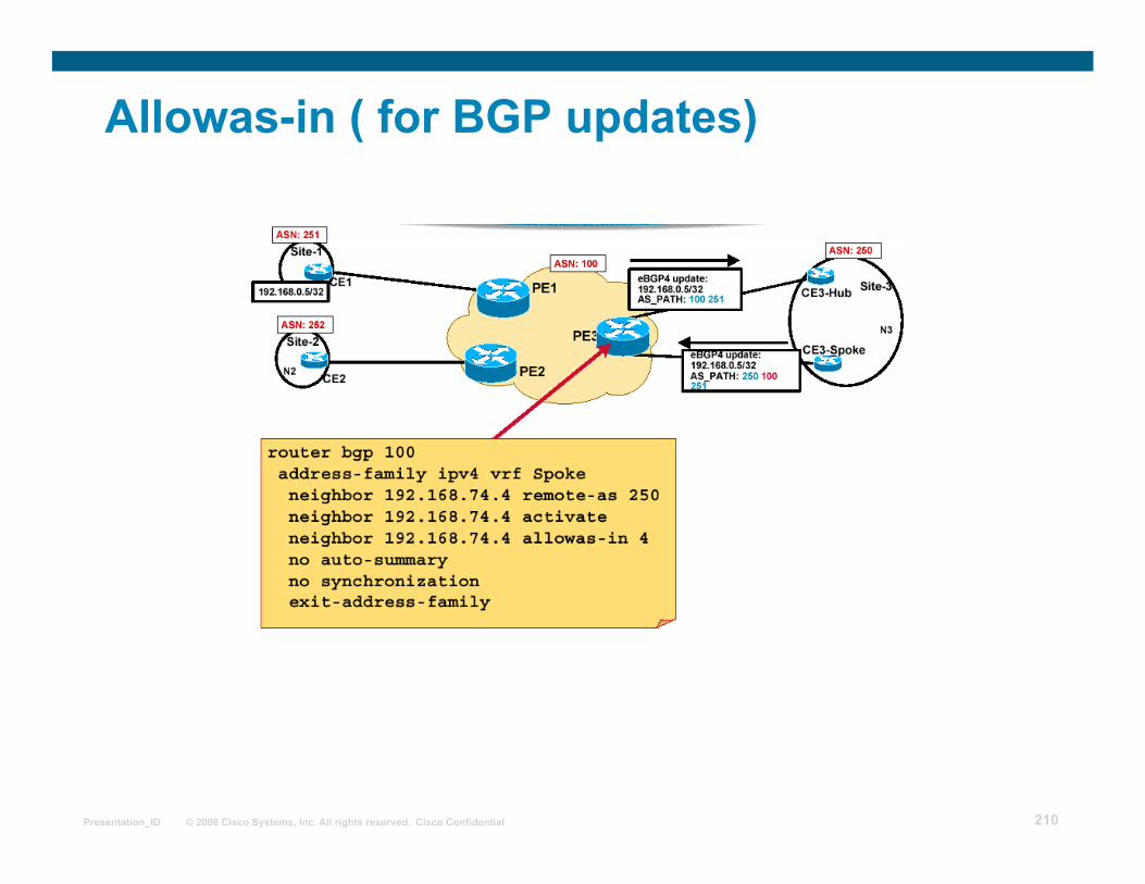
Hub & Spoke Topology Data Flow
• Traffic from one spoke to another will travel across the hub site
• Allowas-in has to be configured on the PE3 if the Site-3 is using BGP
Page 210
© 2008 Cisco Systems, Inc. All rights reserved. Cisco Confidential Presentation_ID 210
Allowas-in ( for BGP updates)
Page 211
© 2008 Cisco Systems, Inc. All rights reserved. Cisco Confidential Presentation_ID 211
Allowas-in (Cont.)
The allowas-in BGP option disables the AS path check on the PE router:
The number of occurrences of the PE router AS number is limited to suppress real routing loops.
The limit has to be configured.
The PE router will reject the update only if its AS number appears in the AS path more often than the configured limit.
Page 212
© 2008 Cisco Systems, Inc. All rights reserved. Cisco Confidential Presentation_ID 212
neighbor allowas-in number
Router(config-router)#
• This command disables the traditional BGP AS path check.
• An incoming update is rejected only if the AS number of the PE router appears in the AS path more often than the configured limit.
Allowas-in (Cont.)
Page 213
© 2008 Cisco Systems, Inc. All rights reserved. Cisco Confidential Presentation_ID 213
Allowas-in in Combination with AS-override
Page 214
© 2008 Cisco Systems, Inc. All rights reserved. Cisco Confidential Presentation_ID 214
Implementing SOO for Loop Prevention
AS path-based BGP loop prevention is bypassed with AS-override and allowas-in features.
Page 215
© 2008 Cisco Systems, Inc. All rights reserved. Cisco Confidential Presentation_ID 215
Implementing SOO for Loop Prevention (Cont.)
SOO identifies the Site from which PE router learns a route
The SOO (extended BGP community) can be used to prevent loops in these scenarios.
The SOO is needed only for multihomed sites.
When EBGP is run between PE and CE routers, the SOO is configured through a route map command on a per neighbour basis under address-family ipv4 vrf
For other routing protocols, the SOO can be applied to routes learned through a particular VRF interface
Page 216
© 2008 Cisco Systems, Inc. All rights reserved. Cisco Confidential Presentation_ID 216
Implementing SOO for Loop Prevention (Cont.)
The same Site of Origin attribute must be used for all CE routers that are at the same site, whether or not those CE routers are attached to the same PE.
Distinct Site of Origin attributes must be used for CE routers, which are at distinct sites.
Note that a route must be associated with at most one attribute of this type.
Page 217
© 2008 Cisco Systems, Inc. All rights reserved. Cisco Confidential Presentation_ID 217
route-map name permit seq match conditions set extcommunity soo extended-community-value
Router(config)#
• Creates a route map that sets the SOO attribute
neighbor ip-address route-map name in Router(config-router-af)#
• Applies inbound route map to CE EBGP neighbor
• Configuring inbound SOO also prevents the PE router from sending any routes outbound on this interface with the same SoO as the one set in the route-map
Implementing SOO for Loop Prevention (Cont.)
Inbound EBGP Update
Page 218
© 2008 Cisco Systems, Inc. All rights reserved. Cisco Confidential Presentation_ID 218
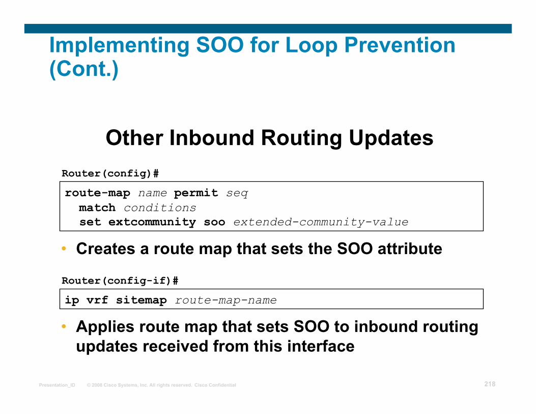
route-map name permit seq match conditions set extcommunity soo extended-community-value
Router(config)#
• Creates a route map that sets the SOO attribute
ip vrf sitemap route-map-name
Router(config-if)#
• Applies route map that sets SOO to inbound routing updates received from this interface
Other Inbound Routing Updates
Implementing SOO for Loop Prevention (Cont.)
Page 219
© 2008 Cisco Systems, Inc. All rights reserved. Cisco Confidential Presentation_ID 219
Selective VRF import/export
Selective import: Specify additional criteria for importing routes into the VRF.
Selective export: Specify additional RTs attached to exported routes.
Page 220
© 2008 Cisco Systems, Inc. All rights reserved. Cisco Confidential Presentation_ID 220
Configuring Selective VRF Import
VRF import criteria might be more specific than just the match on the RT—for example:
Import only routes with specific BGP attributes (community, and so on).
Import routes with specific prefixes or subnet masks (only loopback addresses).
A route map can be configured in a VRF to make route import more specific.
Page 221
© 2008 Cisco Systems, Inc. All rights reserved. Cisco Confidential Presentation_ID 221
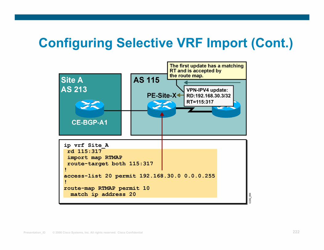
import map route-map
Router(config-vrf)#
• This command attaches a route map to the VRF import process.
• A route is imported into the VRF only if at least one RT attached to the route matches one RT configured in the VRF and the route is accepted by the route map.
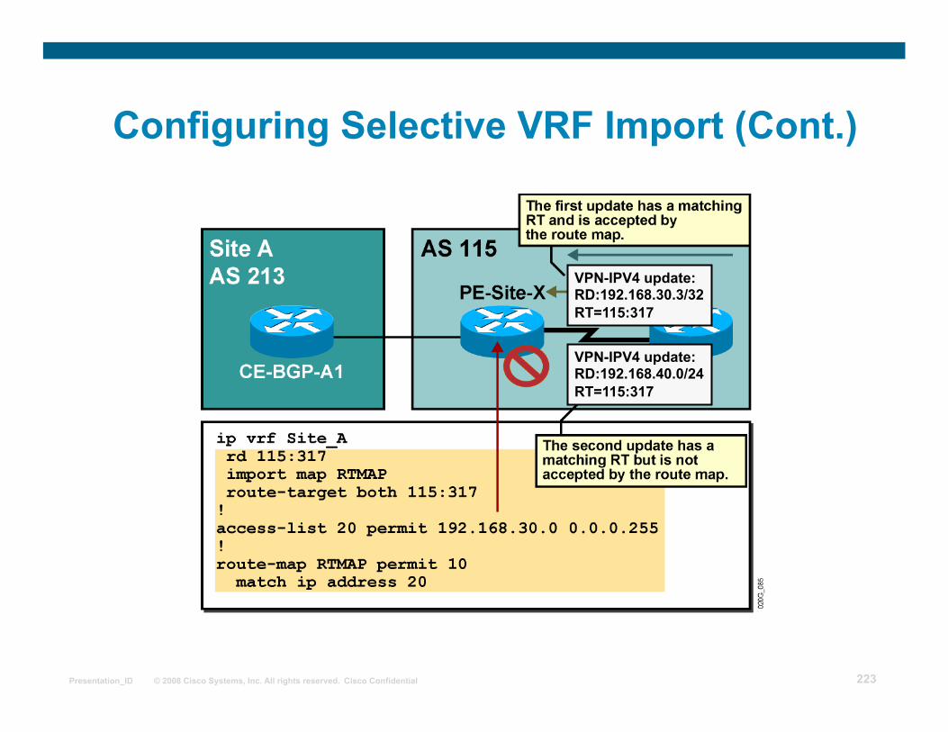
Configuring Selective VRF Import (Cont.)
Page 222
© 2008 Cisco Systems, Inc. All rights reserved. Cisco Confidential Presentation_ID 222
Configuring Selective VRF Import (Cont.)
VPN-IPV4 update: RD:192.168.30.3/32 RT=115:317
Page 223
© 2008 Cisco Systems, Inc. All rights reserved. Cisco Confidential Presentation_ID 223
Configuring Selective VRF Import (Cont.)
VPN-IPV4 update: RD:192.168.40.0/24 RT=115:317
VPN-IPV4 update: RD:192.168.30.3/32 RT=115:317
Page 224
© 2008 Cisco Systems, Inc. All rights reserved. Cisco Confidential Presentation_ID 224
Configuring Selective VRF Export
Routes from a VRF might have to be exported with different RTs:
An example would be export management routes with particular RTs.
An export route map can be configured on VRF: This route map can set extended community RTs.
No other set operations can be performed by this route map.
Page 225
© 2008 Cisco Systems, Inc. All rights reserved. Cisco Confidential Presentation_ID 225
route-map name permit seq match condition set extcommunity rt extended-community-value [additive]
Router(config)#
• This command creates a route map that matches routes based on any route map conditions, and sets RTs.
Configuring Selective VRF Export (Cont.)
Page 226
© 2008 Cisco Systems, Inc. All rights reserved. Cisco Confidential Presentation_ID 226
export map name
router(config-vrf)#
• This command attaches a route map to the VRF export process.
• All exported routes always get RTs configured with route-target export in the VRF.
• A route that is matched by the export route map will have additional RTs attached.
Configuring Selective VRF Export (Cont.)
Page 227
© 2008 Cisco Systems, Inc. All rights reserved. Cisco Confidential Presentation_ID 227
Configuring Selective VRF Export (Cont.)
Page 228
© 2008 Cisco Systems, Inc. All rights reserved. Cisco Confidential Presentation_ID 228
Summary
PE-CE routing protocols need to be configured for individual VRFs
Per-VRF routing protocols are configured as individual address families belonging to the same routing process
An AS number can be reused using: As-override Allowas-in
The SOO can be used to provide protection from routing loops.
Route import and export within VRFs can be controlled with import and export route maps.
Page 229
© 2008 Cisco Systems, Inc. All rights reserved. Cisco Confidential Presentation_ID 229
Summary The MPLS VPN architecture introduces a routing model where a BGP
backbone is inserted into the customer network.
Traditional OSPF-BGP interactions would imply that the OSPF routes received from one customer site would be inserted as external OSPF routes into other customer sites.
The OSPF superbackbone was introduced in MPLS VPN architecture to support the transparency requirements.
The OSPF route type carried in the MP-BGP update received by the PE router is used to generate a summary LSA in the OSPF topology database.
An additional bit (called the down bit) is used in the Options field of the OSPF header to prevent routing loops between MP-BGP and OSPF.
The same bit is also used on the PE routers to prefer MP-BGP routes over OSPF routes derived from MP-BGP routes through redistribution.
Page 230
© 2008 Cisco Systems, Inc. All rights reserved. Cisco Confidential Presentation_ID 230