59
FP7-Sardana SARDANA A Next Generation PON with extended reach and debits António Teixeira Instituto de Telecomunicações, Universidade de Aveiro (UA), Aveiro, Portugal
| Date post: | 08-Jul-2018 |
| Category: |
Documents |
| Upload: | nguyenliem |
| View: | 217 times |
| Download: | 0 times |

FP7-Sardana
SARDANAA Next Generation PON withextended reach and debits
António Teixeira
Instituto de Telecomunicações, Universidade de Aveiro (UA), Aveiro, Portugal

..2 NGON- Seminar 14° of April 2009 (ISCTE, Lisbon) [email protected]
Oveview of the talk
• SARDANA
– Presentation
– General motivations
– Consortium
– Network general presentation
– Driving forces (Gpon actual…)
– Technological solutions
• Transmission
• Remote nodes
– Architectural solution coverage
• Conclusions
..3 NGON- Seminar 14° of April 2009 (ISCTE, Lisbon) [email protected]
SARDANA
Activity: ICT-1-1.1 - Network of the FutureGrant agreement n.: 217122 (SARDANA)STREP: 2008-2010, 2.6 MEuro
Scalable
Advanced
Ring-based passive
Dense
Access
Network
Architecture”
www.ict-sardana.eu

..5 NGON- Seminar 14° of April 2009 (ISCTE, Lisbon) [email protected]
Who is doing it?
Participant name Short name Country
1 Universitat Politecnica de
CatalunyaUPC Spain
2 France Telecom / Orange FT France
3 Tellabs TELLABS Finland
4 Intracom S.A. Telecom Solutions IntraCOM Greece
5 Instituto de Telecomumicações IT Portugal
6 High Institute of Communication
and Information Technology ISCOM Italy
7 Research and Education
Laboratory in Information Tech.AIT Greece

..6 NGON- Seminar 14° of April 2009 (ISCTE, Lisbon) [email protected]
Who is doing it?
Profiles and expertises UPC FT TLB ICOM IT ISC AIT
Netw.&Serv. Operator X
PON equipment provider X planned
Service platform provider X
WDM-PON expertise X X
Monitoring techniques X X
Impairment compensation X X
Semiconductor photonics X X X
Remote amplification X X X
High bit-rate systems X X
UPC: Coordination, ONU, RN subsystems.
FT: Architecture definition, ONU, Field-trial, Technical management, Techno-Economic studies.
Tellabs: GPON equipment, MAC, lab-demonstration.
IntraCOM: Management &Control plane, Service platform.
IT: Monitoring system, non-linear transmission.
ISCOM: Remote nodes, non-linear amplification.
AIT: Electronic PON impairment compensation, Techno-Economic studies.

..7 NGON- Seminar 14° of April 2009 (ISCTE, Lisbon) [email protected]
Fundamental goals
• Maximize:
– N. served users (>1000 per fibre ring)
– Served area (100Km)
– Served capacity (10Gbit/s x 32)
• Minimize:
– Infrastructure COST• N. Fibres / cables
• N. Cabinets
• N. Active areas
• Civil work investments
• Musts:
– Passive external plant
– Single fibre access
– Scalability and upgradeability
– Compatibility with g/e-PON MAC
– Robustness: • Protection
• Monitoring and electronic compensation
UNLIMITED PON
..8 NGON- Seminar 14° of April 2009 (ISCTE, Lisbon) [email protected]
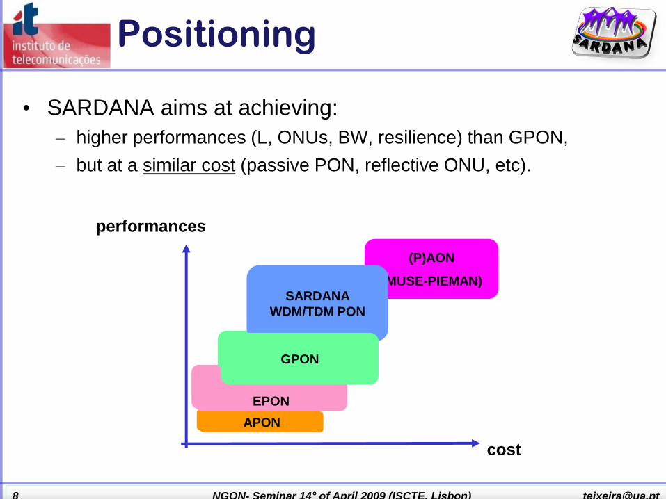
Positioning
• SARDANA aims at achieving:
– higher performances (L, ONUs, BW, resilience) than GPON,
– but at a similar cost (passive PON, reflective ONU, etc).
(P)AON
(MUSE-PIEMAN)
APON
EPON
GPON
SARDANA
WDM/TDM PON
cost
performances
APON
EPON
GPON

..9 NGON- Seminar 14° of April 2009 (ISCTE, Lisbon) [email protected]
CO
RN1 RN2
RNi
RNj
RNN RNN-1
1:K
ONU
ONU
1:K
ONU
ONU
ONU
ONU
1:K
RSOA ONU
D
m+1,…, D
2N
WDM RING
TDM TREE
D
1,…, D
m
Downstream Signals
Upstream Signals
U
1,…, U
2N
U
1,…, U
2N
Bidirectional Transmission
PIN/APD
ON
U
ONU
ONU
ONU
ONU
ONU
SARDANA architecture
SARDANA PON
• Resilient trunk
• Fully passive
• Hybrid: •WDM Metro ring•TDM Access trees
• Cascadable remote nodes
• Colourless ONU• RSOA• Tunable laser
• New adoption of remotely-pumped amplification
• Multi-operator
• Based on GPON, but transparent.

..10 NGON- Seminar 14° of April 2009 (ISCTE, Lisbon) [email protected]
SARDANA equipment
1. Added: standard GPON (MAC) + SARDANA
2. Integrated: adapted GPON + SARDANA
SARDANA ONT
SARDANA CO
Standard
10G-GPON
OLT
Optical
Interface
SARDANA
PON
Standard
10G-PON
ONTSERVICE
PLATFORM
MUX
&
PUMP
&
ROUT.
&
MONIT.
Standard
10G-GPON
OLT
Optical
Interface
Standard
xPON
OLT
Optical
Interface
refl.optical
Interface
CONTROL
(control&management, monitoring, compensation)
better optics than GPON in OLT
worse performances of optics
than ngGPON in ONU

..11 NGON- Seminar 14° of April 2009 (ISCTE, Lisbon) [email protected]
MAC, the Control and Management planes
FUNCTIONALITIES:
• Resilience
• Multi-operator capability
• Multi-rate coexistence
• Control&Management planes
• 10G DBA MAC
• In-service monitoring
• Impairment-aware routing
• Eye-safeness
SARDANA
PHYSICAL LAYER
SARDANA
MAC LAYERSARDANA
IMPAIRMENT
MONITOR.
&
COMPENSAT.
SYSTEMS PHY
MONITORS
PHY
COMPENS.
MAC
MONITORS
MAC
COMPENS.
Standard
10G-GPON
OLT-ONT
Standard
10G-GPON
MAC
SARDANA
CONTROL & MANAGEMENT PLANES
SERVICE
PLATFORM
Functional layered model of SARDANA.
Multi-layer system

..12 NGON- Seminar 14° of April 2009 (ISCTE, Lisbon) [email protected]
The evolution towards…
Ring
Back-scattering+
Protection
Another Ring
RNPay as you grow

..13 NGON- Seminar 14° of April 2009 (ISCTE, Lisbon) [email protected]
Passive Outside Plant
Centralized light generation
Higher User Density >1000
Long reach – 100km
Symmetric 100Mbps
Scalability
Resiliency
Traffic Balance
Multi Operability
Remote Amplification
Sardana…
..14 NGON- Seminar 14° of April 2009 (ISCTE, Lisbon) [email protected]
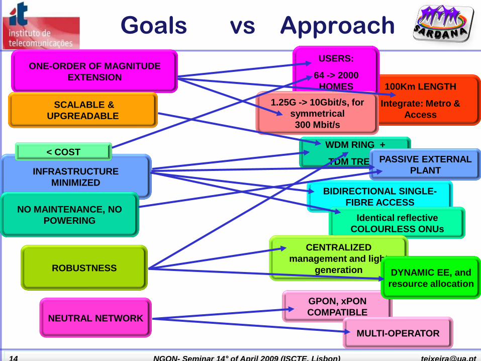
WDM RING +
TDM TREES
GPON, xPON
COMPATIBLE
INFRASTRUCTURE
MINIMIZED BIDIRECTIONAL SINGLE-
FIBRE ACCESS
Goals vs Approach
Identical reflective
COLOURLESS ONUs
NO MAINTENANCE, NO
POWERING
ROBUSTNESS
100Km LENGTH
Integrate: Metro &
Access
USERS:
64 -> 2000
HOMES
1.25G -> 10Gbit/s, for
symmetrical
300 Mbit/s
PASSIVE EXTERNAL
PLANT
< COST
NEUTRAL NETWORK
ONE-ORDER OF MAGNITUDE
EXTENSION
CENTRALIZED
management and light
generation
MULTI-OPERATOR
SCALABLE &
UPGREADABLE
DYNAMIC EE, and
resource allocation

..15 NGON- Seminar 14° of April 2009 (ISCTE, Lisbon) [email protected]
CO
RN1 RN2
RNi
RNj
RNN RNN-1
ON
U
ONU
ONU
ONU
1:K
ONU
ONU
ON
U
ONU
1:K
ONU
ONU
1:K
ONU
ONU
ONU
ONU
1:K
RSOA ONU
D
m+1,…, D
2N
WDM RING
TDM TREE
D
1,…, D
m
Downstream Signals
Upstream Signals
U
1,…, U
m
U
m+1,…, U
2N
Bidirectional Transmission
basic modules• WDM ring: Transport & Resilience
– up to 1.2Tbit/s (64 for 2000 users)
• TDM trees:
– Up to 3 for 3 operators sharing common
infrastructure.
• Passive Remote Nodes (RN):
– Cascadable Add&Drop
– 2-to-1 fibre interface
– Remotely pumped (from CO) optical
amplification by EDFs
– Athermal splitters and fixed filters
• CO (OLT):
– Centralizes the light generation and control
– Stack of lasers serving TDM trees
– Standard G/E-PON equipment adapted to SARDANA
– WDM is used for wavelength routing at the central ring
– DBA techniques for TDM trees.
• Simplest colourless ONU:
– In line with techno-
economical guidelines
– High speed RSOA of
SOA+REAM for up-stream
remodulation

..16 NGON- Seminar 14° of April 2009 (ISCTE, Lisbon) [email protected]
Impact over infrastructure
• Elimination of maintenance in external fibre plant.
• Reduction of the number of active central offices.
• Integration: Head-end & Metro node
AC
B
Redon
Equipements WDM sur chaque arc optique
Present Sardana
FT/Orange
(specimen)
Central
Edificio 1
CasaTree Tree Tree
Usuario Caseta
en vía pública
Fibra Óptica en canalización
subterránea
Suministro
eléctrico
Central
Edificio 1
CasaTree Tree Tree
Usuario
Nodo Remoto enterrado
Fibra Dopada con Erbio Fibra Óptica en
canalización subterránea
INSTALACIONES ACTUALES ngPON

..17 NGON- Seminar 14° of April 2009 (ISCTE, Lisbon) [email protected]
Impact of OLT location
DSLAM 820 CO
DSLAM with fiber link Master DSLAM
Edge node on 1st and 2nd
transmission ring
Edge node only on primary
transmission ring
Point of Presence POP
649 CO 277 CO
45 CO 11 CO 2 CO

..18 NGON- Seminar 14° of April 2009 (ISCTE, Lisbon) [email protected]
40
30
20
10
0
0 2 4 6 8 10 12
Optical reach (km)
CO
num
ber
Hypothesis : Urban area
(big town - Paris)
3 CO / 10 km
37 CO / 3.5 km
FTTH impact on network architecture

..19 NGON- Seminar 14° of April 2009 (ISCTE, Lisbon) [email protected]
Maximum reach OLT-users
Impact of OLT location
0
20
40
60
80
100
120
140
160
180
200
s5 s4 s3 s2 s1 s0
POPDSLAM DSLAM
with fiber
Master
DSLAMEdge node
1&2 and 1 ring
Mean reach OLT-users
Re
ach
, km
Maximum SARDANA
distance
..20 NGON- Seminar 14° of April 2009 (ISCTE, Lisbon) [email protected]
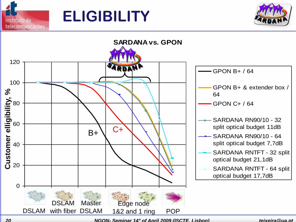
SARDANA vs. GPON
0
20
40
60
80
100
120
0,5 1,5 2,5 3,5 4,5 5,5 6,5
GPON B+ / 64
GPON B+ & extender box /
64
GPON C+ / 64
SARDANA RN90/10 - 32
split optical budget 11dB
SARDANA RN90/10 - 64
split optical budget 7,7dB
SARDANA RNTFT - 32 split
optical budget 21,1dB
SARDANA RNTFT - 64 split
optical budget 17,7dB
ELIGIBILITYC
usto
mer
ell
igib
ilit
y, %
POPDSLAM
DSLAM
with fiber
Master
DSLAMEdge node
1&2 and 1 ring
B+ C+

..21 NGON- Seminar 14° of April 2009 (ISCTE, Lisbon) [email protected]
GPON evolution
• Migration topics :
– We are focussing on a fibre lean scenario where Next Generation
Access solution coexists on same fibres as GPON
– Maximum re-utilization of optical infrastructure installed (ring and ODN)
• Wavelength plan allocation
Use the WDM to achieve system generation overlay
(G.984.5).
1200 1300 1400 1500 1600
Existing 1310
upstreamExisting 1490
downstream
New Enhancement
Band definition
1530-1625
GPON
Wavelength, nm

..22 NGON- Seminar 14° of April 2009 (ISCTE, Lisbon) [email protected]
SARDANA & G-PON G.984.5
Specification Value
Loss without
connectors – G-
PON wavelength
span
< 0.7dB (1260-
1500nm)
Loss without
connectors for
enhancement
bands
<1.0dB (1524-1625nm)
Isolation – COM –
OLT (1524-
1625nm)
TBD (> 30dB (higher
values may be
required depending
on the application))
Isolation – COM –
UPGRADE
(1480-1500nm,
1260-1360nm)
> 30dB
Max optical power +23dB
Return Loss > 50dB
Directivity > 50dB
NOTE 1 - The wavelength range of 1524-1530nm
should not be used by NGA downstream signals.
NOTE 2 - The specification of WDM1 in the range of
1625-1660 nm for applications such as inserting an
OTDR signal onto the PON is for future study.
OLT
COM
UPGRADE
1260-1360nm
1480-1500nm 1524-1625nm
1260 -1360nm
1480-1500nm
1524-1625nm
MUX "WDM1"

..23 NGON- Seminar 14° of April 2009 (ISCTE, Lisbon) [email protected]
Standardization position
• Standardization :
IEEE 10GEPON : (standard for end of 2009)
– 3 classes (20 – 24 – 29 dB)
– Wavelength allocation :
• Upstream : 1270nm [1260 -1280nm]
• Downstream : 1577nm [1575-1580nm]
– SARDANA could use IEEE chipset
•
• FSAN / ITU : (standard ITU G.987 for 2012)
– SARDANA will be present in the white paper NG-PON2 of the FSAN
(published beginning of 2010) .

FP7-Sardana
How are we evolving towards the solution?
..25 NGON- Seminar 14° of April 2009 (ISCTE, Lisbon) [email protected]
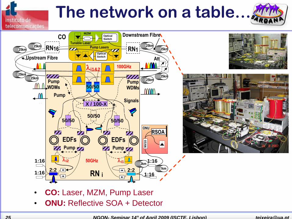
The network on a table…
• CO: Laser, MZM, Pump Laser
• ONU: Reflective SOA + Detector
1:16
RN i
Pump WDMs
Signals
i1&2
Pump
EDFs
2:2
50/50
X / 100-X
1:16
i1
50/50
Pump WDMs
Pump
EDFs
50/50
2:2
1:16
1:16
2km i2
100GHz
50GHz
Pump
1km
50/50
RSOA ONU
90
/10
CO Downstream Fibre
Upstream Fibre
Optical
Switch
Pump Lasers
MZM
Tunable Laser
Optical
Switch
RN16 RN1
25km 25km
25km 25km
Att
25km 25km 25km
25km

..26 NGON- Seminar 14° of April 2009 (ISCTE, Lisbon) [email protected]
The SARDANA Scenarios
Two main scenarios have been considered
With the main characteristics of the elements as the following:
Aiming to guarantee -15 dBmat the ONU input and -28 dBmat the OLT pre amp receiver.OLT output considered in twocases: 0 dBm and 10 dBm

..27 NGON- Seminar 14° of April 2009 (ISCTE, Lisbon) [email protected]
ONU
• ONU
– Collourless
– Cheap
– Compatible with GPON
• Solutions
– SROA
• Gain
• Reflective (single fiber)
– Tuneable laser
• No remodulation
– Highr stability at the ONU
– Other
ONU represents about 80% of network cost*
(excluding P2P)
*: R.I. Martinez et al, “A Low Cost Migration Path Towards Next Generation Fiber-To-The-Home Networks”,
ONDM 2007, LNCS 4534, pp 86-95 (2007)

..28 NGON- Seminar 14° of April 2009 (ISCTE, Lisbon) [email protected]
RSOA-Colorless ONU
• Potential low cost device
• Input Signal & E/O
BW trade-off:
– Bandwidth limited at small signal levels
• Measurements at: 20 ºC, 80 mA, 1550 nm
– 15dB gain at -15dBm input power, but only 0.7GHz BW.
– Gain saturation is required (~0dB gain) for 1.3GHz
0
0.2
0.4
0.6
0.8
1
1.2
1.4
-30 -20 -10 0 10
RSOA Input Power (dBm)
Mo
d. B
W a
t -3
dB
(G
Hz) BW@-3dB (GHz)
Bandwidth Measurements of commercial RSOA

..29 NGON- Seminar 14° of April 2009 (ISCTE, Lisbon) [email protected]
The ONU: focus on the SOA
• At the ONU, the presence of Semiconductor Optical Amplifiers (Reflective), for re-
use of the wavelength determine a deep study in terms of current/input power in
order to understand the better AO (AREA of OPERATION).

..30 NGON- Seminar 14° of April 2009 (ISCTE, Lisbon) [email protected]
ONU status
• Tellabs Modified OLT and ONU optics in Tellabs 1134 system
• Integrated RSOA based ONU for the first Demo at 1.25Gbps (Optoway module in photography) from France Telecom.
• 3-5Labs has provided higher BW SOA/REAM that have been mounted, tested and adapted for 10G at UPC.
Colourless ONT & OLT
First tests of 3-5Labs SOA/REAM chips
GPON ONT first prototype from Tellabs for
2.5/1.25Gbps using RSOA modules from France
Telecom

..31 NGON- Seminar 14° of April 2009 (ISCTE, Lisbon) [email protected]
ONU OLT
• Reflective-ONU optical transceiver:
• preferred option as cheapest available choice for the WDM-PON
• Main drawbacks:
• Full-duplex with wavelength reuse in down&up-stream
• -> Solution: study of the possible optical modulation formats compensating techniques like: downstream ER cancellation at ONU, wavelength dithering and adaptive electronic equalization.
Colourless ONT (end-user terminal)
OLT
MZM
Bias
Driver
C-Band
1550 nmPlaser
10kHz
ditheringBias
Downstream
Data TX
Upstream
Data RX A
mp
2.5G/1.25G
GPON
CardDownstream
Upstream
Am
p
EDFAG
Am
p
(*) 10kHz dithering for Rayleigh combating
IM/IM
Coupler
Am
p
APD LP Filter
3
ONU
RSOA
2,5Gbps
G
2
1
Am
p
G
GNF
IL
Downstream
Data RX
Upstream
Data TX
On/Off
Swicht
2.5G/1.25G
GPON
Card
down RX
+
Equ +
PreEmph
SOADLDL
APDAPD LPFRF
amp
Equalizer
Clock
Recovery
bias
ER monitordown ER
ER monitor up ER
up copy
MAC
Bias
τ
RF amp
RF ampdownstream
cancellation
up TX
var. delay
bias
point
+
d/dt
RF
ampLPF
PIN
TX
RX
Monitoring

..32 NGON- Seminar 14° of April 2009 (ISCTE, Lisbon) [email protected]
ONT OLT
• OLT Optical Modules:
• Laser source dithered for RB and reflections impairments mitigation
• Implementations:
• The OLT based on Direct Modulated Laser (DML):
• Cost-effective
• Rayleigh-backscattering tolerant (trade-off of dispersion)
• OLT based on a external modulated laser
• Higher performance
• Lower CD impairments.
Colourless ONT & OLT definition
RN1 RN2
RNi
RNj
RNN RNN-1
1:K
ON
U
ONU
1:K
ONU
ONU
ON
U
ONU
1:K
D
m+1,…, D
2N
WDM RING TDM TREE
D
1,…, D
m
Downstream Signals
Upstream Signals
U
1,…, U
2N
U
1,…, U
2N
ONU
ONU
ONU
ONU
ONU
ONU
EDFA
Pre-Amp
APD
Am
p
G
Am
p
G
NF
OLT-RX
OLT-RX
OLT-TX
MZM
Am
p
bias10 kHz
dithering
Am
p
EDFA
C-Band Laser
1550 nm
10
Gbps
G
OLT-TX
Downstream
Data TX
Upstream
Data RX
COOLT-TX
OLT-TX
OLT-RX
OLT-RX
Coupler
Am
p
LP Filter
3
ONU
RSOA
2,5Gbps
2
1
Am
p
G
G
G, NFIL
Downstream
Data RX
Upstream
Data TX
Burst
Enable
2.5G/1.25G
GPON
Card
APD
10 G/.2.5G
GPON
Card
2 OLT TX implementation considered: a) Low-cost DML; b) High performance external
modulated laser
Bias Am
p
EDFA
Driver
C-Band
1550 nm
G
10kHz dithering
GPON
Downstream
Data TX
Upstream Data RX
Am
p
Am
p
OLT
DML
Laser
a) Detailed scheme of a OLT based on
a Direct Modulated Laser (DML)First prototype of the optical modules of 2.5 Gbps
OLT based on DML

..33 NGON- Seminar 14° of April 2009 (ISCTE, Lisbon) [email protected]
ONT OLT
• Reflective-ONU optical transceiver:
• Main drawbacks:
• RSOA electro-optical bandwidth limitation
• -> Solution: off-set optical receiver filtering and DFE/FFE equalization at the OLT
• low-cost RSOAs rated for 1.25Gbps operation that can be used in future PONs modulated at 2.5 and even 10 Gb/s in up-stream [1]
• By removing the down-stream crosstalk, the distance has been increased up to 70Km [2].
Colourless ONT (end-user terminal)
(Up): Upstream 10Gb/s BER versus OSNR with 25
km bidirectional and two fibres of 25 km
unidirectional .
(Down): BER versus OSNR with 12 km bidirectional
and 2x25 km unidirectional.
18 20 22 24 26 28 30 3210
9
8
7
6
5
4
3
-Lo
g (
BE
R)
OSNR (dB)
1 Fiber-W/O DFE
1 Fiber-WITH DFE
2 Fibers-W/O DFE
2 Fibers-WITH DFE
10 12 14 16 18 20 22 24 26 2810
9
8
7
6
5
4
3
-Lo
g (
BE
R)
OSNR (dB)
Upstream-W/O DFE
Upstream-WITH DFE
Downstream
[1]: M. Omella et al., “Full-Duplex Bidirectional Transmission at 10
Gbps in WDM PONs with RSOA-based ONU using Offset
Optical Filtering and Electronic Equalization”, OFC‟2009.
[2]: I. Papagiannakis, et al., “Investigation of 10-Gb/s RSOA-
Based Upstream Transmission in WDM-PONs Utilizing
Optical Filtering and Electronic Equalization,” IEEE Photon.
Technol. Lett., vol. 20, no.24, pp. 2168-2170 December
2008.

..34 NGON- Seminar 14° of April 2009 (ISCTE, Lisbon) [email protected]
ONU related stuff
• In order to remodulate we have to
– Have convenient modulation format
• Power in the „0‟s
• Cheap to achieve remodulation
• Receiver sensitivity of -25dBm

..36 NGON- Seminar 14° of April 2009 (ISCTE, Lisbon) [email protected]
Rayleigh BackScattering
• The relation between the Signal and the Rayleigh backscattering (oSRR), in a
determined point of the network, is very important in the SARDANA scenario.
• Considering the Network Parameters, a desidered value for the oSRR has been
set to >20 dB.

..37 NGON- Seminar 14° of April 2009 (ISCTE, Lisbon) [email protected]
Rayleigh BackScattering
• RB effect is most relevant and degrading at the RN input.
• Mitigation techniques can be: laser linewidth broadening, cross remodulation (C-L bands), FEC, chirped
modulation, Carrier Suppressed sub carrier amplitude modulated phase shift keiyng, frequency ditering, et alt

..38 NGON- Seminar 14° of April 2009 (ISCTE, Lisbon) [email protected]
Losses
• We have
several
losses in
the
network.
Propagation
losses
RN insertion losses
Splitting losses
Propagation
losses
Passive
Pumps
Raman
EDF
Pump absorption

..39 NGON- Seminar 14° of April 2009 (ISCTE, Lisbon) [email protected]
Use of 2 EDFs instead of 4Save of 3dB of pump power
budgetEDF for DS / EDF for USAbility to adjust differential
gain for DS and US depending on the EDF length.
Remote Node evolution

..40 NGON- Seminar 14° of April 2009 (ISCTE, Lisbon) [email protected]
For RN close to the CO noamplification is required.
Optical Switching selectsAmplification and NonAmplification module.
Extra efficiency can be achieved.
Remote Node evolution

..41 NGON- Seminar 14° of April 2009 (ISCTE, Lisbon) [email protected]
Static Coefficient
Excess Power Drop
Reduced Efficiency
Dual Case Reconfigurability
Improved Efficiency
Extra Loss (switches)
Multi Case Reconfigurability
No Excess Pump Power Drop
Higher Efficiency
Remote Node evolution

..42 NGON- Seminar 14° of April 2009 (ISCTE, Lisbon) [email protected]
The key is an Optical Power HarvestingModule
Optical power is converted and storedelectrically
Electrical Power is responsible for poweringthe Optical Switch.
Switches can be remotely controlled fromthe CO
No local power source is necessary
The network has a truly outside passiveplant. In sleep mode energy is stored
Switching optical controlsensitivity of -25dBm
Remote Node evolution

..43 NGON- Seminar 14° of April 2009 (ISCTE, Lisbon) [email protected]
In sleep mode energy is stored
Switching optical controlsensitivity of -25dBm
Remote Node evolution

..45 NGON- Seminar 14° of April 2009 (ISCTE, Lisbon) [email protected]
RN impairments
• Insertion losses
• Central wavelength stability
• Reflections
• EDF gain transients ->
Possible impairments at
the RN:
Transient effects vs. pump power 65µs / 125µs
Transient effects vs. signal input power 65µs / 125µs
In accordance with EDFA dynamics modeling
Gain transients mitigation
• Automatic Gain Controlled
• Optical Feedback Loop
• Larger effective Area EDF
• Burst mode (Upstream) gain stabilization by continuous stream signal (Downstream)

..46 NGON- Seminar 14° of April 2009 (ISCTE, Lisbon) [email protected]
However it works...
• Design, construction, modelling and characterization of Remote Node designs based in fixed Add&Drops.
• Proof-of-concept experiments using a RSOA based ONU [1]:
• Downstream @ 10 Gbps half-duplex 1024 ONUs and 50 km (corresponding to 1024 ONUs &100km in non fibre-failure case).
• Upstream @ 2.5 Gbps for 1024 ONUs along 50 km, even for the worst conditions of fiber cut.
• Upstream @ 1.25 Gbps 1024 ONUs along 100km (for worse resilience case of fibre failure) at 1.25Gbps.
"Remote Node test and models
1:K RN i
Signals
i1
50/50
1:K/2
1:K/2
i2
50/50
i1&2
WDM WDM Pass band
filter
90/10
RN i
ED
Fs
90/10
90/10 90/10
1:K
ED
Fs
50/50
1:K/2
1:K/2
50/50
i2 i2 i1 i1
1.E-11
1.E-10
1.E-09
1.E-08
1.E-07
1.E-06
1.E-05
1.E-04
1.E-03
1.E-02
-35 -33 -31 -29 -27 -25
Signal Power [dBm]
BE
R
B2B
RN4 @ 50km
RN4 @ 25km
RN8 @ 25km
Expon. (B2B)
Expon. (RN4@ 50km)Expon. (RN8@ 25km)Expon. (RN4@ 25km)
10GbpsDownstream
1543.74nm
1.E-11
1.E-10
1.E-09
1.E-08
1.E-07
1.E-06
1.E-05
1.E-04
1.E-03
1.E-02
-45 -40 -35 -30 -25 -20
Signal Power (dBm)B
ER
B2B(RSOA_In= -20 dBm)
B2B(RSOA_In=-15 dBm)
After RN(RSOA_In=-15 dBm)
RN16 @50km
Expon.(B2B(RSOA_In=-15 dBm))Expon.(B2B(RSOA_In= -20 dBm))Expon.(After RN(RSOA_In=-15 dBm))
2.5GbpsUpstream1530.33nm
1.E-11
1.E-10
1.E-09
1.E-08
1.E-07
1.E-06
1.E-05
1.E-04
1.E-03
1.E-02
-40 -35 -30 -25 -20
Signal Power (dBm)
BE
R
B2B(RSOA_In=-20 dBm)
RN16 @100km
Expon.(B2B(RSOA_In=-20 dBm))Expon.(RN16 @100km )
1.25Gbps
Upstream1530.33nm
[1]: J.A. Lazaro, J. Prat, P. Chanclou, G. M. Tosi Beleffi, A. Teixeira, I.
Tomkos, R. Soila, V. Koratzinos, “Scalable Extended Reach PON”,
paper OTHL2, OFC/NFOEC 2008.

..47 NGON- Seminar 14° of April 2009 (ISCTE, Lisbon) [email protected]
-11
-10
-9
-8
-7
-6
-5
-4
-3
-2
-37 -36 -35 -34 -33 -32 -31 -30 -29 -28 -27 -26 -25 -24 -23 -22
ONU input power [dBm] , OLT input power [dBm]
log
(Bit
Err
or
Rati
o)
DS, ER=3dB
DS, ER>10dB
US, ER=3dB
US, ER=0dB
However it works
• Design:
• fixed Add&Drops
• bidirectional amplification (3dB pump power reduction)
• for full duplex operation
• using RSOA
• downstream cancellation techniques.
"Remote Node test and models"
Experimental conditions:
• Ring Length: 100 km
• Splitting Ratio: 1:32
• Drop Length: 10 km
• Downstream at 2.5 Gb/s
• Upstream at 1.25 Gb/s
• Sensitivities reached (ERdown = 3dB, BER = 10e-10)
• Downstream (2.5Gb/s): -25.2 dBm
• Upstream (1.25): -22.6 dBm
1:16
RN i
Signals
i1&2
2:2 1:16
2:2
1:16
1:16
2km
i1
100GHz
50GHz
1km
50/50
i1
Common
Rest
i2
Upstream (ERdown=3dB), without
/ with cancellation

..48 NGON- Seminar 14° of April 2009 (ISCTE, Lisbon) [email protected]
OSNR
• Noise sources from DFA, RAMAN and remote amplification techniques fully explored. Gain, NF and oSNR explored for Individual configurations as:
– In-line EDF
– Drop EDF
– Raman
• Combined configurations requirecombination of different models:
– Raman + In-line EDF
– Raman + Drop EDF (explored)
– Raman + In-line + Drop EDF
– In-line EDF + Drop EDF
• Results demonstrates that all the remote technologies can provideoSNR not lower that 22 dB matchingthe goal of 21.4 dB oSNR proposed.
• Analisys performed on additional noisecontributions as RBS, Reflections, Down stream cancellation techniquesand Gain Transients.

..49 NGON- Seminar 14° of April 2009 (ISCTE, Lisbon) [email protected]
WDM RINGTDM TREE
DownStream Fiber
UpStream
Fiber
RN 1
RN 2
RN 3
RN 4 RN 5
RN 16
RN 7
RN 6
RN 13 RN 12
RN 8
RN 15
RN 14
RN 9
RN 11
RN 10
RN 12
RN 16 RN 8
P.P.1
P.P.2 FIBER CUT
• Comparison between the RN architectures:
• Non Optical Switching• Dual Optical Switching• Tuneable Power Splitting• Reconfigurable RN
• …for fiber cut at RN8, RN12, RN16
• System parameters• Ring Size of 20, 40 and 60Km• 16RN• Tree size of 2Km• 2 trees per RN• 32 users per tree• 100Mbit/s per user
SARDANA - Resilience

..50 NGON- Seminar 14° of April 2009 (ISCTE, Lisbon) [email protected]
NOS - Non Optical Switching
OS - Dual Optical Switching
TD - Tuneable Pump Drop
REC - Reconfigurable RN
Remote NodeResults Comparison

..51 NGON- Seminar 14° of April 2009 (ISCTE, Lisbon) [email protected]
Remote NodeProposal 3 / Results
REC
Proposed
REC Proposed
• Proposed RN allow extraresiliency and lower Pump Powerconsumed.
• But also extra costs due to theinsertion of more 6 1x4 Opticalswitching, requiring more controlpower.
..52 NGON- Seminar 14° of April 2009 (ISCTE, Lisbon) [email protected]
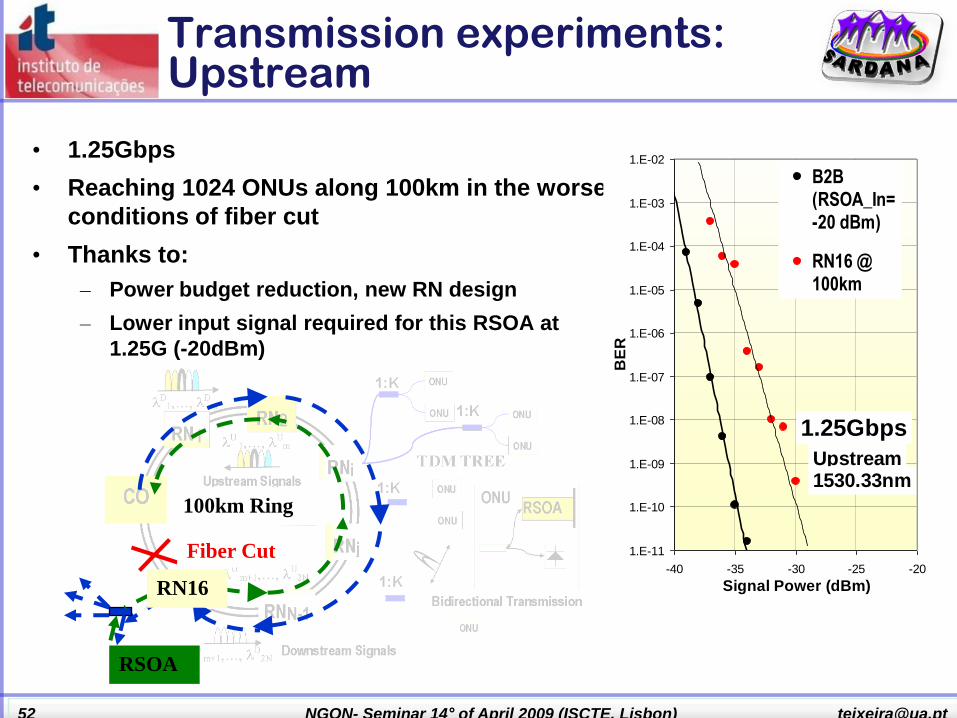
Transmission experiments: Upstream
• 1.25Gbps
• Reaching 1024 ONUs along 100km in the worse
conditions of fiber cut
• Thanks to:
– Power budget reduction, new RN design
– Lower input signal required for this RSOA at
1.25G (-20dBm)
1.E-11
1.E-10
1.E-09
1.E-08
1.E-07
1.E-06
1.E-05
1.E-04
1.E-03
1.E-02
-40 -35 -30 -25 -20
Signal Power (dBm)
BE
R
B2B(RSOA_In=-20 dBm)
RN16 @100km
Expon.(B2B(RSOA_In=-20 dBm))Expon.(RN16 @100km )
1.25Gbps
Upstream1530.33nm
Fiber Cut
RSOA
RN16
100km Ring

..53 NGON- Seminar 14° of April 2009 (ISCTE, Lisbon) [email protected]
How to react…
• Monitoring
• Upper layers detection
• OTDR (physical layer)

..54 NGON- Seminar 14° of April 2009 (ISCTE, Lisbon) [email protected]
OTDR monitor in SARDANA
Trace in black: λ = 1553 nm; λFBG1 = 1550.2 nm; λFBG2 =
1551.4 nm Experimental Setup
Trace in black: λFBG1 = 1550.2 nm;
Trace in pink: λFBG2 = 1551.4 nm

..55 NGON- Seminar 14° of April 2009 (ISCTE, Lisbon) [email protected]
FFE/DFE Electronic compensation
• Experimental test using an FFE/DFE module with following characteristics:
– Operation at 10Gb/s with 2 samples per symbol
– Independent FFE (up to 5-taps) and FFE/DFE (up to 2-tap DFE) operation
– Built-in Clock recovery
• Experimental activities targeted the following: (independently and in combination
with WP-Sy):
– 10Gb/s EML transmission distance improvement
– 2.5Gb/s DMLs operated at 10Gb/s with FFE/DFE and off-set-filtering
• CD compensation
• SPM and non-linear effects
– 10Gb/s DML with low ER and DFE/FFE at receiver (to be combined with properties of
remodulation using RSOA)
– Equalization of remodulated upstream signal from RSOA
– Bidirectional transmission to examine effects in tree distribution fibre
Results to be presented in upcoming deliverables and associated new publications

..56 NGON- Seminar 14° of April 2009 (ISCTE, Lisbon) [email protected]
Demo setup - 2009
OLTa OLTb
10G Switch
Optics
RN1 RN2
ONU1a ONU1b ONU2bONU1b
ODN2ODN1
CPE CPE OMCI
OMCI
Craft
Craft
Service Nodes
Lab nw Switch
CPC
CPC
2x25km
2x25km
2x25km
20km 5km
1km 1km
Pump station

..57 NGON- Seminar 14° of April 2009 (ISCTE, Lisbon) [email protected]
Project planning and status
• Prototype and test Phases of Sardana:
– Current GPON-compatible 2.5G/1.25G
– 10G/2.5G for Demo
– 10G/10G with advanced tecniques.
ORGANIZATION
STUDY
RESEARCH RESEARCH
DESIGNIMPLEM.
1st PROT.
IMPLEMENTATION
FINAL PROTOTYPE.
RESEARCH
INTEGRATION DEMOs
RESEARCH
•2010•2009•2008
•RISK
•Madeira
•reducing risks:
•construction of the first prototype...
DEMO
•Espoo•Barcelona
•Athens •Paris
ORGANIZATION
STUDY
RESEARCH RESEARCH
DESIGNIMPLEM.
1st PROT.
IMPLEMENTATION
FINAL PROTOTYPE.
RESEARCH
INTEGRATION DEMOs
RESEARCH
•2010•2009•2008
•RISK
•Madeira
•reducing risks:
•construction of the first prototype...
DEMO
•Espoo•Barcelona
•Athens •Paris

..58 NGON- Seminar 14° of April 2009 (ISCTE, Lisbon) [email protected]
Final Outcomes
• SARDANA project targets the ultimate extension of the limits of FTTH Passive Optical Networks, as a practical transparent approach to access&metro convergence.
– Sardana Test-bed Demonstration in Espoo-Finland, with extended scalable reach, number of homes, bandwidth, passively scalable external plant and resiliency.
– Sardana Field-Trial in 2010 in Lannion-France, with new broadband services.
• Network/system/subsystem/component design guidelines and prototypes.
• Contribution to
– Regulatory Bodies on Broadband Access to citizens (multi-operator infrastructure sharing strategy).
– International Standards on next-generation FTTH .

..59 NGON- Seminar 14° of April 2009 (ISCTE, Lisbon) [email protected]
Expected Impacts:
• One order-of-magnitude extension of current PON performances, aimed at overcoming the expected long term limitations of current internet capabilities, architecture and protocols.
• Smooth and increased scalability and backwards compatibility migration solution from currently deployed PONs.
• Establishment of new intelligent monitoring and compensation strategies to combat impairment and faults for a trusted robust PON.
• Implementation of the MAC, the Control and Management planes, to demonstrate basic resiliency, wavelength balancing and improved service-aware traffic control.
• Economic effectiveness of the extended PON approach.
• Demonstration (at UPC, Helsinki Oy and ICT‟2010) and field-trial (in Lannion) of the SARDANA network.
• Formal proposal for a technical solution of a efficient multi-operatorshared broadband infrastructure as an input to international Recommendation and national NGA Regulatory bodies.
• SARDANA will result with experience and IPR that helps industry and research to develop a competitive advantage.


![Sardana: an Automatic Tool for Numerical Accuracy Optimization · Sardana which takes as entry synchronous programs written in Lus-tre [5, 12]. Inputs are represented by abstract](https://static.documents.pub/doc/80x56/6056ce58515d513e42192d8a/sardana-an-automatic-tool-for-numerical-accuracy-optimization-sardana-which-takes.jpg)

