Forty Years of Digital SAR and Slow GMTI Technology John C Kirk Jr, Scott Darden Goleta Star LLC Torrance CA, USA Uttam Majumder, Steven Scarborough AFRL / RYAP, Wright-Patterson AFB OH, USA Abstract - 40-years of digital SAR and Slow GMTI technology is traced from the first system to demonstrate real-time digitally correlated SAR from an intentionally maneuvering platform [1] to the current lite-weight dual-channel radar (DCR) providing simultaneous SAR and GMTI data. The Dual-Channel Radar (DCR) has been developed providing lite-weight SAR GMTI capability for Small UAVs. The prototype radar weighs 5-lbs and has demonstrated the extraction of ground moving targets (GMTs) embedded in high- resolution SAR imagery data. Sum and difference channel data is used in a DPCA algorithm to extract the GMTs and display them on the Sum channel high resolution SAR image. Heretofore this type of capability has been reserved for much larger systems such as the JSTARS. Previously small liteweight SARs featured only a single channel and only displayed SAR imagery. With the advent of this new capability, SAR GMTI performance is now possible for small UAV class radars for DoD and DHS applications. The DCR is the culmination of multiple Phase II and Phase II plus SBIR efforts over the past 10-years, since 2002, for the Army, DARPA and AFRL. I. INTRODUCTION Synthetic Aperture Radar development began in the 1950’s. The first operational SARs used post-flite ground based optical processing to produce sidelooking strip maps. Digital Signal Processing (DSP) which began in the 1960s showed the promise for providing real-time SAR imaging. The first real- time digital SAR flew in 1971 [1-3]. Digital SAR development has continued thru the years and has progressed along with the evolution of the key technologies for digital processing. Real-time digitally processed SAR imagery is now commonplace on many applications. Some highlights of this SAR technology development are summarized in Table 1. The application of multi-channel techniques for Moving Target Indication (MTI) has been applied to airborne radars over the past 50 plus years. Slow GMTI (Ground MTI) techniques have been developed over the last 40 plus years to provide for the detection and location of slow moving ground targets from an airborne radar [4-27]. With a single channel radar, a fast GMT can be detected. With the addition of a second channel, either a lower Table 1. Selected Highlights of SAR Imaging Radar Evolution PERIOD PHASE CHARACTERISTICS 50’s Concept - Carl Wiley DBS concept Development - U of Ill Experiment - Project Michigan / Wolverine 60’s Optical SAR - optical processing - non-real time 70’s Digital SAR - real time reconnaissance via data link - tactical / strategic precision NAV update and weapons delivery - space based SAR 80’s Inverse SAR - target imaging via target motion and not radar motion 90’s Matured SAR - Commercial Off The Shelf (COTS) components - advanced algorithms - world wide 00’s UAV SAR - Application of SAR to UAVs - Miniaturization of SAR for Small UAVs Minimum Detectable Velocity (MDV) can be achieved or improved accuracy target azimuth geolocation can be achieved. With two channels, there is a choice between either low MDV or accurate geolocation via monopulse processing. For detecting slow moving targets the primary technique is Displaced Phase Center Antenna (DPCA), or Along Track Interferometry (ATI). At least three subapertures or phase centers are required to both detect and geolocate ground moving targets. The leading application of this technology is the Joint Surveillance and Target Acquisition Radar System (JSTARS). Clutter Suppressed Interferometry (CSI) is the name given to the JSTARS three phase center approach. Much work is continuing on slow GMTI development. There are one, two, three and four phase center slow GMTI approaches. And, it has been postulated to go to more phase centers for potentially improved performance, via Space Time Adaptive Processing (STAP). DPCA is essentially the simplest form of STAP with just two spatial degrees of freedom. Although developed for traditional Linear SAR, researchers have recently applied the DPCA principle to Circular SAR data. Both SAR and GMTI can be accomplished in a drag beam strip mode or in a scanning beam Wide Area 978-1-4799-2035-8/14/$31.00@2014 IEEE 0064
Transcript
Forty Years of Digital SAR and Slow GMTI Technology
John C Kirk Jr, Scott Darden Goleta Star LLC
Torrance CA, USA
Uttam Majumder, Steven Scarborough AFRL / RYAP,
Wright-Patterson AFB OH, USA Abstract - 40-years of digital SAR and Slow GMTI technology is traced from the first system to demonstrate real-time digitally correlated SAR from an intentionally maneuvering platform [1] to the current lite-weight dual-channel radar (DCR) providing simultaneous SAR and GMTI data. The Dual-Channel Radar (DCR) has been developed providing lite-weight SAR GMTI capability for Small UAVs. The prototype radar weighs 5-lbs and has demonstrated the extraction of ground moving targets (GMTs) embedded in high-resolution SAR imagery data. Sum and difference channel data is used in a DPCA algorithm to extract the GMTs and display them on the Sum channel high resolution SAR image. Heretofore this type of capability has been reserved for much larger systems such as the JSTARS. Previously small liteweight SARs featured only a single channel and only displayed SAR imagery. With the advent of this new capability, SAR GMTI performance is now possible for small UAV class radars for DoD and DHS applications. The DCR is the culmination of multiple Phase II and Phase II plus SBIR efforts over the past 10-years, since 2002, for the Army, DARPA and AFRL.
I. INTRODUCTION Synthetic Aperture Radar development began in the 1950’s. The first operational SARs used post-flite ground based optical processing to produce sidelooking strip maps. Digital Signal Processing (DSP) which began in the 1960s showed the promise for providing real-time SAR imaging. The first real-time digital SAR flew in 1971 [1-3]. Digital SAR development has continued thru the years and has progressed along with the evolution of the key technologies for digital processing. Real-time digitally processed SAR imagery is now commonplace on many applications. Some highlights of this SAR technology development are summarized in Table 1. The application of multi-channel techniques for Moving Target Indication (MTI) has been applied to airborne radars over the past 50 plus years. Slow GMTI (Ground MTI) techniques have been developed over the last 40 plus years to provide for the detection and location of slow moving ground targets from an airborne radar [4-27]. With a single channel radar, a fast GMT can be detected. With the addition of a second channel, either a lower
Table 1. Selected Highlights of SAR Imaging Radar Evolution
PERIOD PHASE CHARACTERISTICS 50’s Concept - Carl Wiley DBS concept
Development - U of Ill Experiment - Project Michigan / Wolverine
60’s Optical SAR - optical processing - non-real time 70’s Digital SAR - real time reconnaissance via data link
- tactical / strategic precision NAV update and weapons delivery - space based SAR
80’s Inverse SAR - target imaging via target motion and not radar motion 90’s Matured SAR - Commercial Off The Shelf (COTS) components
- advanced algorithms - world wide
00’s UAV SAR - Application of SAR to UAVs - Miniaturization of SAR for Small UAVs
Minimum Detectable Velocity (MDV) can be achieved or improved accuracy target azimuth geolocation can be achieved. With two channels, there is a choice between either low MDV or accurate geolocation via monopulse processing. For detecting slow moving targets the primary technique is Displaced Phase Center Antenna (DPCA), or Along Track Interferometry (ATI). At least three subapertures or phase centers are required to both detect and geolocate ground moving targets. The leading application of this technology is the Joint Surveillance and Target Acquisition Radar System (JSTARS). Clutter Suppressed Interferometry (CSI) is the name given to the JSTARS three phase center approach. Much work is continuing on slow GMTI development. There are one, two, three and four phase center slow GMTI approaches. And, it has been postulated to go to more phase centers for potentially improved performance, via Space Time Adaptive Processing (STAP). DPCA is essentially the simplest form of STAP with just two spatial degrees of freedom. Although developed for traditional Linear SAR, researchers have recently applied the DPCA principle to Circular SAR data. Both SAR and GMTI can be accomplished in a drag beam strip mode or in a scanning beam Wide Area
978-1-4799-2035-8/14/$31.00@2014 IEEE 0064
Search (WAS) mode. This WAS SAR Doppler Beam Sharpening (DBS). resolution is generally not as fine common Strip mode. The E-2C Hexample of WAS MTI, and WAS GMTon the JSTARS.
II. First Real-Time Digita The first real time in-flight processedwas flown on 18 March 1971. It wprogram called the Future Weapon C(FWCS). That system eventuallymotion compensation with the motionsensor being an Inertial Navigation integrated with a Doppler Nav System.it was desired to show the benefprocessing relative to optical. These wtime in-flight on-board processinsidelooking SAR, ie squint mode, andImage Formation Processing (IFP) duri The early SARs all used non-realprocessing. The look angle wassidelooking, and the aircraft flew a flight path which was a tube with a wid50-feet. We sought to show that we conon-orthogonal squint angel, with 45-the nominal choice. We also establisabout 4-nmi width in which the maneuver. This is illustrated in Fig. 1processing was accomplished and deFWCS during 1971.
Fig. 1. Digital SAR Squint Mode Imaging durManeuvering
An example image of the Washington during intentional maneuvers is shownadditional expanded image is shown infrom a long 45-degree strip of the Baltishowing the inner harbor area. A image is shown for comparison. Th
is often called The DBS
as the more Hawkeye is an TI is performed
al SAR
d digital SAR was part of a
Control System y incorporated n measurement System (INS) . At that time fits of digital
were: (1) Real-ng, (2) non-d (3) strip SAR ing maneuvers.
l-time ground s 90-degreees ‘sitting duck’
dth of typically ould image at a -degrees being shed a tube of aircraft could . This type of monstrated on
ring Intentional
DC area taken n in Fig. 1. An n Fig. 2. It is imore MD area Google Earth
he images are
approximately aligned up. features can be noticed betweenradar vs optical, and 1971 vs changes in the inner harbor in paimage was obtained during inten± 10-deg and ± 2000-ft. We werthe gimbal angle limit of 60-degthe pilot to keep the maneuvers were no noticeable degradationgeometric fidelity and linearitaccurately preserved during these
Fig. 2. Comparison of 1971 SAR image
III. GMTI Tech
The single phase center GMTI apon a large antenna, a slow radar RF for achieving a good MDV. clear of Main Beam Clutter (MLocation is poor since only ampavailable. However, multi-racould be used for cross range locMulti-lateration Surveillance Strof the 1970’s was such an approa Two phase centers permits detecin clutter via DPCA, with interferometric repositioning for available. Three and four phasallow for both DPCA and monopPeak-a-Boo (PAB) evolved frommoving target located near the single channel radar. Locating acorrectly repositioning it is cal(GMTL), or geolocation. Impphase centers for achieving a lowslow GMTI, or sometimes SMTI. The three / four phase center apprphase centers or degrees of freedclutter canceling and monopulDoppler filters that are in the MB
Several interesting n these two images,
2013. Notice the articular. This SAR
ntional maneuvers of re limited mostly by
grees. So, we asked < ±15-degs. There
ns in the image, as ty appeared to be e maneuvers.
and 2013 Optical Image
hniques
pproach relies solely velocity and a high Targets have to be
MBC) for detection. litude centroiding is dar multi-lateration
cation accuracy. The rike System (MSSS) ch.
ction of slow movers no monopulse or the detected targets
e center approaches pulse simultaneously. m trying to locate a
skirt of MBC in a a moving target and lled GMT Location plementing multiple
w MDV is also called .
roaches have enough dom to provide both lse location in the C region.
978-1-4799-2035-8/14/$31.00@2014 IEEE 0065
DPCA Processing DPCA achieves its clutter rejection by aligning the apertures in space on two successive PRIs. Thus clutter cancellation by a two pulse canceller should be near perfect. In practice the two pulse cancellation is applied after Doppler filtering individually and adaptively on each Doppler filter. Hence it looks and performs about the same as CSI. A very simple view of DPCA clutter canceling is presented here. Consider the simple geometry illustrated in Fig. 3. For this simple case there is a single piece of clutter. Consider a pair of pulses. The radar transmits and receives on the fore antenna at time t1 and then transmits and receives on the rear antenna at time t2. These two events are labeled 1 and 2 in the figure.
Fig. 3. DPCA GMTI Clutter Canceling Concept To cancel the clutter, the two returns are aligned and subtracted. For perfect DPCA, the two phase centers will overlay and the clutter will cancel exactly. This is normally accomplished by aligning the antenna with the velocity vector and adjusting the radar timing. Even if the phase centers don’t overlay, the clutter can still be cancelled, by phase shifting one of the returns relative to the other prior to subtraction. Adaptive DPCA Concept Even for the case where the two phase centers don’t overlay, clutter canceling can be implemented by phase shifting or complex weighting one return with respect to the other. For example the sum S1 – K*S2 is always equal to zero if K is set equal to S1 / S2. In general the two returns are complex. The ratio is given by A1 ejφ1 / A2 ejφ2 = A1 / A2 ej(φ1 – φ2). If the amplitude of the two returns is the same, the ratio will provide a phase shift. Thus the adaptive weight is determined from the data itself. The ratio S1 / S2 is normally formed as (S1 S2*) / (S2 S2*) so that the denominator is a real number. The key to the more complex clutter rejection approach is a straightforward extension of this simple concept. The two-channel adaptive DPCA processing is illustrated functionally in Fig. 4.
Fig. 4. Dual-Channel Adaptive DPCA FFT Processing FFT or SAR Doppler Processing The real key to adaptive DPCA is to perform the clutter canceling subtraction after FFT Doppler processing. Doppler filtering divides the antenna MBC clutter return into smaller (SAR or DBS) angular regions. Adaptive DPCA can then be applied on each Doppler filter individually. This approach provides greater clutter canceling than doing 2-pulse DPCA prior to the FFT.
IV. Highlights of Multi-channel GMTI
Development Some highlights of slow MTI development are presented here, and a summary is given in Fig. 5. The USN AEW Hawkeye radar is included here, even though it is an AMTI (Airborne) and not a GMTI radar, since it uses DPCA to minimize the MBC Doppler spread and improve Doppler visibility between the PRF lines. Actually that radar had a major design problem to eliminate the ground movers and leave the airborne targets. Hence, inadvertently, overland it became a GMTI radar.
Fig. 5. Highlights of Multi-Channel GMTI Development
USN E-2C Hawkeye UHF AMTI - 2 Phase Center DPCA
- Unintentionally had GMTI capability over land
MIT/LL Multiple Antenna Surveillance Radar
(MASR)
- 4 Phase Center, DPCA plus Monopulse
USAF Joint STARS
- 3 Phase Center, DPCA plus Monopulse
Dual Channel Radar (DCR) - 2 Phase Center, DPCA or Monopulse
V
2
1
978-1-4799-2035-8/14/$31.00@2014 IEEE 0066
During the 70’s, a Multi-lateration Surveillance Strike System (MSSS) approach was developed, and it is interesting since it sought to detect ground moving targets and then to reposition them through multiple aircraft multi-lateration. The problem being that there is an uncertainty in the targets cross range location comparable to the antenna beamwidth which can be kilometers wide at long range, whereas the range resolution can be down to tens of meters. Thus wide angle multi-lateration using range should reduce the cross range accuracy to that comparable to the range accuracy. During the same time span, MIT/LL flew their four phase center MASR. MASR sought to do DPCA and precision monopulse location from a single radar. The problem being that monopulse and DPCA require two phase centers each. The phase centers are degrees of freedom (DOF) and if they are used for DPCA they cannot be used for monopulse. Thus the four phase center approach provides independent DOFs for both DPCA and monopulse. Pave Mover was a competitive program to develop a slow GMTI surveillance system. There were two contractors. Grumman flew a Norden three phase center approach and Hughes flew a two phase center approach. The Hughes approach was an outgrowth of their Monopulse Anomaly Detection (MAD) concept which was flown earlier on the USAF FLAMAR program. The USAF selected Grumman-Norden and this became the JSTARS system. - Thus, in summary and as was mentioned in the introduction, there are one, two, three and four phase center slow GMTI approaches. And it has been postulated to go to even more phase centers for potentially improved performance; hence STAP. DPCA is essentially the simplest form of STAP with just two spatial degrees of freedom.
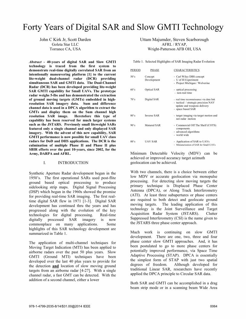
V. Dual-Channel Radar Description Legacy light-weight Goleta Ka-band radar technology has evolved into the sub-10-lb Ka-band dual-channel radar (DCR). This legacy radar hardware has been upgraded and modified to provide along track dual phase center data collections to support SAR / GMTI algorithm development. The radar is liteweight and can be scanned in azimuth and elevation over a wide FOV. In the bottom of Fig. 5 and in the right side of Fig. 6, we show the three antenna aperture front end that has been assembled, a center antenna for transmit and two outer antennas for receive. The two receive arrays feed a dual-channel receiver. A special digital dual-channel FPGA board has been developed and is used to
accept the output from the two receiver channels. The Motion Measurement Sensor (MMS) is provided by a good performance 2-lb INS/GPS. The complete system underwent final lab checkout and additional van testing in September 2010. Initial flight testing was performed in February 2011 with excellent results. This dual-channel Ka-band data will compliment existing X and Ku-band data bases and expand the frequency coverage to the higher MMW region. Quick-look processing is used in-flight to verify the data. The collected data has been processed by multiple image formation processing (IFP) algorithms: a simple Back Projection Algorithm (BPA), Wavefront Reconstruction (RMA or ω-k) and with the Polar Format Algorithm (PFA). The initial flight test was performed in a 4-passenger Cessna 172 aircraft, enabling the collection of data that is independent of the ground station. This aircraft is illustrated in the left side of Fig. 6. The airborne DCR is installed in the luggage compartment. A view of the DCR in the luggage compartment is also shown in Fig. 6. The components in this initial flite test configuration weigh approximately 11-lbs including the radar, MMS and gimbal, and have a total power draw of less than 100-Watts.
Fig. 6. Goleta Star Aircraft for DCR Data Collections, and showing the Radar inside the Cargo Door
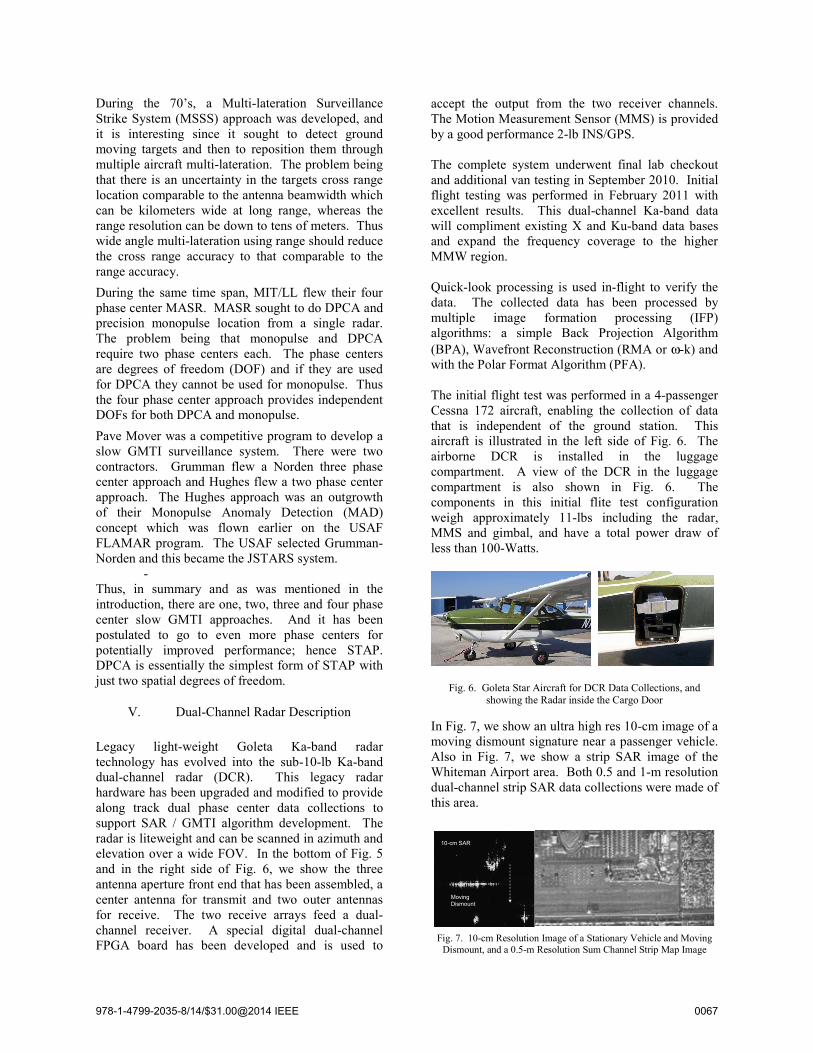
In Fig. 7, we show an ultra high res 10-cm image of a moving dismount signature near a passenger vehicle. Also in Fig. 7, we show a strip SAR image of the Whiteman Airport area. Both 0.5 and 1-m resolution dual-channel strip SAR data collections were made of this area.
Fig. 7. 10-cm Resolution Image of a Stationary Vehicle and Moving Dismount, and a 0.5-m Resolution Sum Channel Strip Map Image
Moving Dismount
10-cm SAR
978-1-4799-2035-8/14/$31.00@2014 IEEE 0067
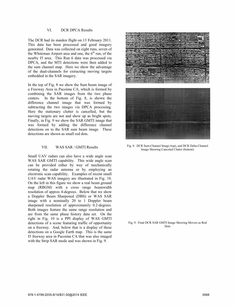
VI. DCR DPCA Resu The DCR had its maiden flight on 13 FThis data has been processed and generated. Data was collected on eightthe Whiteman Airport area and one, thenearby I5 area. This Run 6 data was DPCA, and the MTI detections were the sum channel map. Here we show of the dual-channels for extracting membedded in the SAR imagery. In the top of Fig. 8 we show the Sum ba Freeway Area in Pacoima CA, whichcombining the SAR images from thcenters. In the bottom of Fig. 8, difference channel image that wasubtracting the two images via DPCHere the stationary clutter is cancemoving targets are not and show up aFinally, in Fig. 9 we show the SAR GMwas formed by adding the differdetections on to the SAR sum beam detections are shown as small red dots.
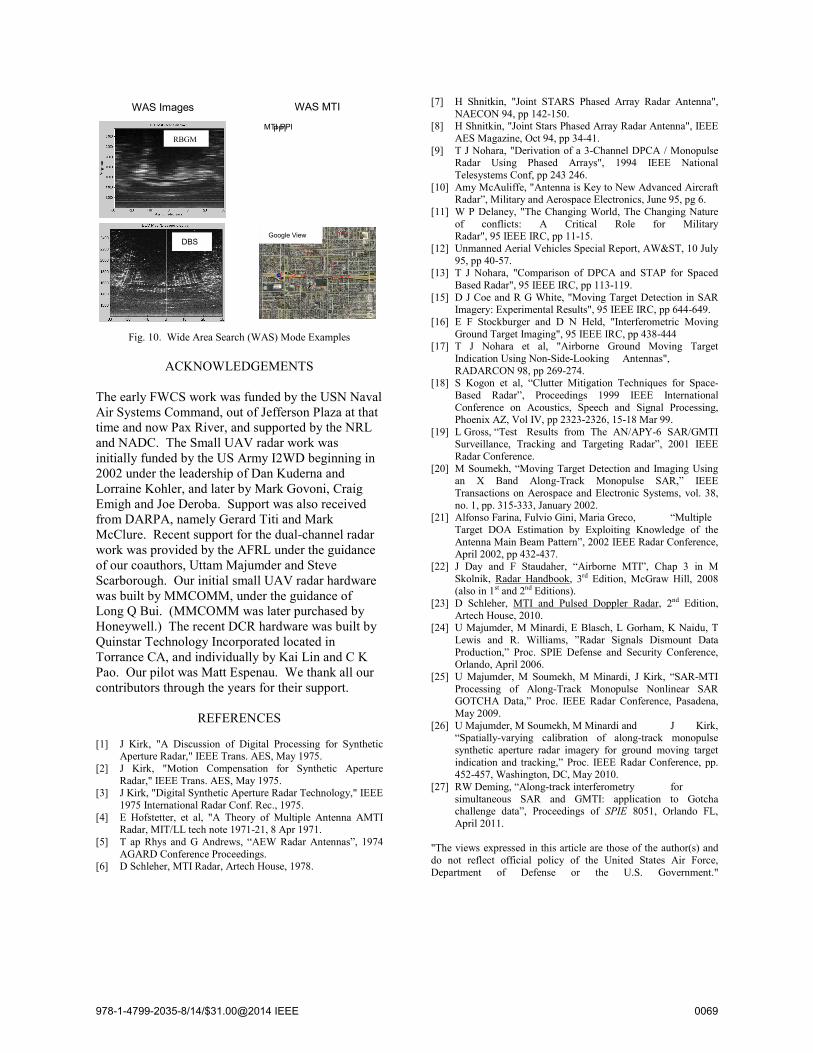
VII. WAS SAR / GMTI R Small UAV radars can also have a wWAS SAR GMTI capability. This wcan be provided either by way of rotating the radar antenna or by electronic scan capability. Examples oUAV radar WAS imagery are illustratOn the left in this figure we show a reamap (RBGM) with a cross rangresolution of approx 4-degrees. Belowa Doppler Beam Sharpened (DBS) oimage with a nominally 20 to 1 Dsharpened resolution of approximatelBoth images feature the same range are from the same phase history dataright in Fig. 10 is a PPI display ofdetections of a scene featuring traffic on a freeway. And, below that is a didetections on a Google Earth map. ThI5 freeway area in Pacoima CA that wawith the Strip SAR mode and was show
ults
February 2011. good imagery
t runs, seven of e 6th run, of the processed via then added to the advantage
moving targets
beam image of h is formed by he two phase is shown the
s formed by CA processing. elled, but the as bright spots. MTI image that rence channel image. These
Results
wide angle scan wide angle scan f mechanically employing an of recent small ted in Fig. 10.
al beam ground ge beamwidth w that we show or WAS SAR Doppler beam ly 0.2-degrees. resolution and a set. On the f WAS GMTI of opportunity isplay of these his is the same as also imaged
wn in Fig. 9.
Fig. 8. DCR Sum-Channel Image (top),
Image Showing Canceled Clu
Fig. 9. Final DCR SAR GMTI Image S
Dots
and DCR Delta-Channel utter (bottom)
Showing Movers as Red
978-1-4799-2035-8/14/$31.00@2014 IEEE 0068
Fig. 10. Wide Area Search (WAS) Mode Examples
ACKNOWLEDGEMENTS The early FWCS work was funded by the USN Naval Air Systems Command, out of Jefferson Plaza at that time and now Pax River, and supported by the NRL and NADC. The Small UAV radar work was initially funded by the US Army I2WD beginning in 2002 under the leadership of Dan Kuderna and Lorraine Kohler, and later by Mark Govoni, Craig Emigh and Joe Deroba. Support was also received from DARPA, namely Gerard Titi and Mark McClure. Recent support for the dual-channel radar work was provided by the AFRL under the guidance of our coauthors, Uttam Majumder and Steve Scarborough. Our initial small UAV radar hardware was built by MMCOMM, under the guidance of Long Q Bui. (MMCOMM was later purchased by Honeywell.) The recent DCR hardware was built by Quinstar Technology Incorporated located in Torrance CA, and individually by Kai Lin and C K Pao. Our pilot was Matt Espenau. We thank all our contributors through the years for their support.
REFERENCES [1] J Kirk, "A Discussion of Digital Processing for Synthetic
Aperture Radar," IEEE Trans. AES, May 1975. [2] J Kirk, "Motion Compensation for Synthetic Aperture
[8] H Shnitkin, "Joint Stars Phased Array Radar Antenna", IEEE AES Magazine, Oct 94, pp 34-41.
[9] T J Nohara, "Derivation of a 3-Channel DPCA / Monopulse Radar Using Phased Arrays", 1994 IEEE National Telesystems Conf, pp 243 246.
[10] Amy McAuliffe, "Antenna is Key to New Advanced Aircraft Radar”, Military and Aerospace Electronics, June 95, pg 6.
[11] W P Delaney, "The Changing World, The Changing Nature of conflicts: A Critical Role for Military Radar", 95 IEEE IRC, pp 11-15.
[12] Unmanned Aerial Vehicles Special Report, AW&ST, 10 July 95, pp 40-57.
[13] T J Nohara, "Comparison of DPCA and STAP for Spaced Based Radar", 95 IEEE IRC, pp 113-119.
[15] D J Coe and R G White, "Moving Target Detection in SAR Imagery: Experimental Results", 95 IEEE IRC, pp 644-649.
[16] E F Stockburger and D N Held, "Interferometric Moving Ground Target Imaging", 95 IEEE IRC, pp 438-444
[17] T J Nohara et al, "Airborne Ground Moving Target Indication Using Non-Side-Looking Antennas", RADARCON 98, pp 269-274.
[18] S Kogon et al, “Clutter Mitigation Techniques for Space-Based Radar”, Proceedings 1999 IEEE International Conference on Acoustics, Speech and Signal Processing, Phoenix AZ, Vol IV, pp 2323-2326, 15-18 Mar 99.
[19] L Gross, “Test Results from The AN/APY-6 SAR/GMTI Surveillance, Tracking and Targeting Radar”, 2001 IEEE Radar Conference.
[20] M Soumekh, “Moving Target Detection and Imaging Using an X Band Along-Track Monopulse SAR,” IEEE Transactions on Aerospace and Electronic Systems, vol. 38, no. 1, pp. 315-333, January 2002.
[21] Alfonso Farina, Fulvio Gini, Maria Greco, “Multiple Target DOA Estimation by Exploiting Knowledge of the Antenna Main Beam Pattern”, 2002 IEEE Radar Conference, April 2002, pp 432-437.
[22] J Day and F Staudaher, “Airborne MTI”, Chap 3 in M Skolnik, Radar Handbook, 3rd Edition, McGraw Hill, 2008 (also in 1st and 2nd Editions).
[23] D Schleher, MTI and Pulsed Doppler Radar, 2nd Edition, Artech House, 2010.
[24] U Majumder, M Minardi, E Blasch, L Gorham, K Naidu, T Lewis and R. Williams, ”Radar Signals Dismount Data Production,” Proc. SPIE Defense and Security Conference, Orlando, April 2006.
[25] U Majumder, M Soumekh, M Minardi, J Kirk, “SAR-MTI Processing of Along-Track Monopulse Nonlinear SAR GOTCHA Data,” Proc. IEEE Radar Conference, Pasadena, May 2009.
[26] U Majumder, M Soumekh, M Minardi and J Kirk, “Spatially-varying calibration of along-track monopulse synthetic aperture radar imagery for ground moving target indication and tracking,” Proc. IEEE Radar Conference, pp. 452-457, Washington, DC, May 2010.
[27] RW Deming, “Along-track interferometry for simultaneous SAR and GMTI: application to Gotcha challenge data”, Proceedings of SPIE 8051, Orlando FL, April 2011.
"The views expressed in this article are those of the author(s) and do not reflect official policy of the United States Air Force, Department of Defense or the U.S. Government."