Manual 3/20/2017 PSFEM5xxxGTxxx Viking Technology Revision F Page 1 of 48 www.vikingtechnology.com SATA 6Gb/s M.2 SATA Manual M.2 SATA is a non-volatile, solid-state storage device delivering Serial ATA performance, reliability and ruggedness for environmentally challenging applications.
Transcript
Manual 3/20/2017
PSFEM5xxxGTxxx Viking Technology
Revision F Page 1 of 48
www.vikingtechnology.com
SATA 6Gb/s
M.2 SATA Manual
M.2 SATA is a non-volatile, solid-state storage device delivering Serial ATA performance, reliability and ruggedness for environmentally challenging applications.
Manual 3/20/2017
PSFEM5xxxGTxxx Viking Technology
Revision F Page 2 of 48
www.vikingtechnology.com
Revision History Date Revision Description Checked By
3/27/15 X1 Initial Release from modified PSFEM4XXXGTXXX_X3 and PN table per PSG
5/07/15 A
Add photo, update per psg. 4/29/15 Change all PN to VPxx., remove 42/60mm references. Change all PN to VPxx., remove 42/60mm references. Remove PFAIL/DATA Hardening signaling. Changed Absolute max Vin 3.6V. Reliability table changed from 72 bit per 1KB to 120 bit per 2KB page. Changed table 4-1 Signal and Power pin 58 to Reserved for MFG_CLOCK
5/13/15 B Revise power consumption table. IOPS per IOmeter8. Add notes to PN table
7/30/15 C Add 15nm PN’s
3/1/16 D Update PN table
9/20/16 E Revise logo and color scheme. Remove temp sensor and SATA attribute.
3/20/17 F Revise note 2 on Extended SMART Attribute Actual Data table
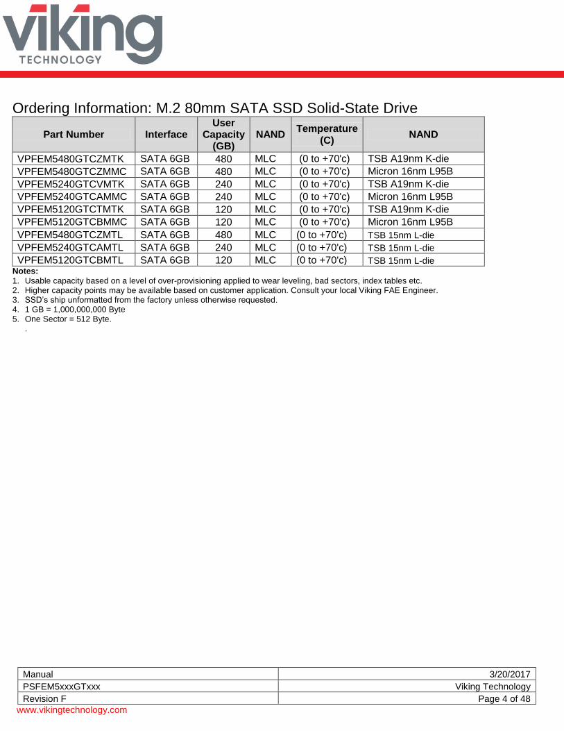
Ordering Information: M.2 80mm SATA SSD Solid-State Drive
Part Number Interface User
Capacity (GB)
NAND Temperature
(C) NAND
VPFEM5480GTCZMTK SATA 6GB 480 MLC (0 to +70'c) TSB A19nm K-die
VPFEM5480GTCZMMC SATA 6GB 480 MLC (0 to +70'c) Micron 16nm L95B
VPFEM5240GTCVMTK SATA 6GB 240 MLC (0 to +70'c) TSB A19nm K-die
VPFEM5240GTCAMMC SATA 6GB 240 MLC (0 to +70'c) Micron 16nm L95B
VPFEM5120GTCTMTK SATA 6GB 120 MLC (0 to +70'c) TSB A19nm K-die
VPFEM5120GTCBMMC SATA 6GB 120 MLC (0 to +70'c) Micron 16nm L95B
VPFEM5480GTCZMTL SATA 6GB 480 MLC (0 to +70'c) TSB 15nm L-die
VPFEM5240GTCAMTL SATA 6GB 240 MLC (0 to +70'c) TSB 15nm L-die
VPFEM5120GTCBMTL SATA 6GB 120 MLC (0 to +70'c) TSB 15nm L-die Notes:
1. Usable capacity based on a level of over-provisioning applied to wear leveling, bad sectors, index tables etc. 2. Higher capacity points may be available based on customer application. Consult your local Viking FAE Engineer. 3. SSD’s ship unformatted from the factory unless otherwise requested. 4. 1 GB = 1,000,000,000 Byte 5. One Sector = 512 Byte.
.
Manual 3/20/2017
PSFEM5xxxGTxxx Viking Technology
Revision F Page 5 of 48
www.vikingtechnology.com
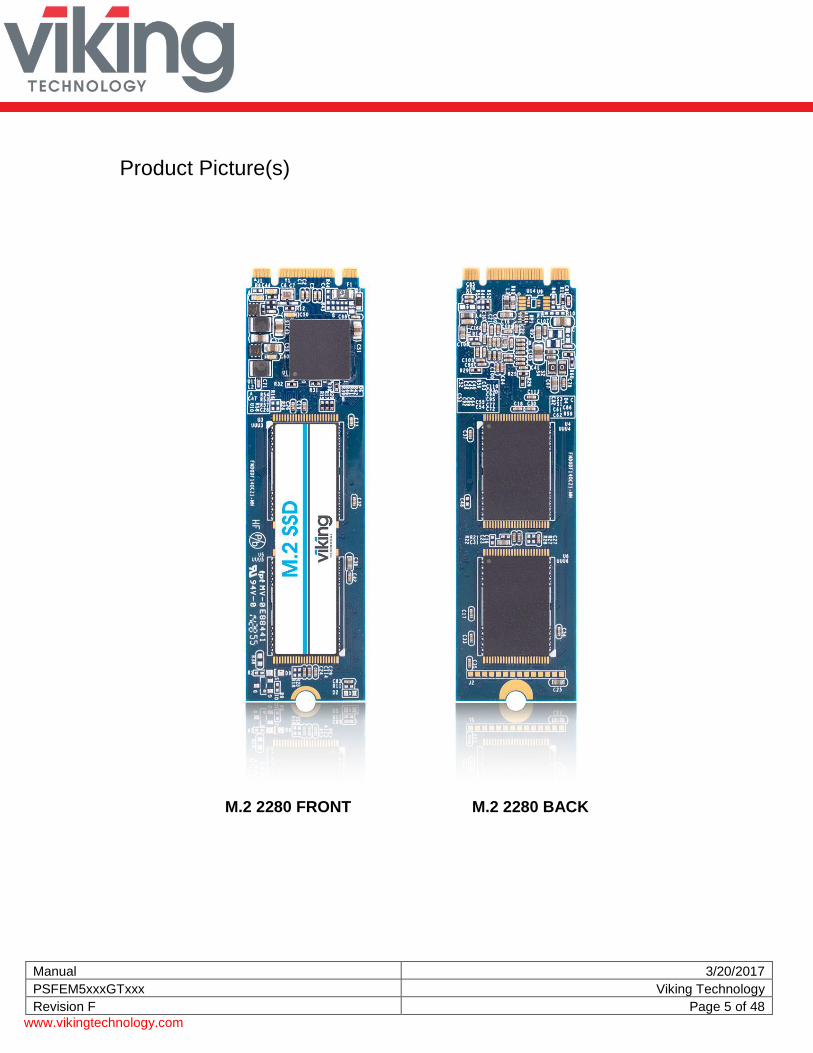
Product Picture(s)
M.2 2280 FRONT M.2 2280 BACK
Manual 3/20/2017
PSFEM5xxxGTxxx Viking Technology
Revision F Page 6 of 48
www.vikingtechnology.com
Enterprise SSD – An Enterprise SSD contains hardware and firmware that detect and manage power failures. This allows the drive to flush the controller cache and harden data to NAND flash. No data is lost or corrupted. .
Manual 3/20/2017
PSFEM5xxxGTxxx Viking Technology
Revision F Page 7 of 48
www.vikingtechnology.com
Table of Contents
1 INTRODUCTION 10
1.1 Features 10
1.2 Block Diagram 11
1.3 SATA Interface 12
2 PRODUCT SPECIFICATIONS 13
2.1 Performance 13
2.2 Timing 13 2.2.1 STANDBY IMMEDIATE Command 13
2.3 Electrical Characteristics 14 2.3.1 Absolute Maximum Ratings 14 2.3.2 Supply Voltage 14 2.3.3 Power Consumption 15
2.4 Environmental Conditions 15 2.4.1 Temperature and Altitude 15 2.4.2 Shock and Vibration 16 2.4.3 Electromagnetic Immunity 16
2.5 Reliability 16
2.6 Data Security 16 2.6.1 Encryption 16 2.6.2 Quick Erase 17 2.6.3 Military Secure Erase / Sanitization/ Purge Routines 18
3 MECHANICAL INFORMATION 29
3.1 Dimensions 29
3.2 Card Edge Detail 31
3.3 M.2 SSD Weight 33
4 PIN AND SIGNAL DESCRIPTIONS 33
Manual 3/20/2017
PSFEM5xxxGTxxx Viking Technology
Revision F Page 8 of 48
www.vikingtechnology.com
4.1 Signal and Power Description Tables 33
4.2 Hot Plug Support 34
5 COMMAND SETS 34
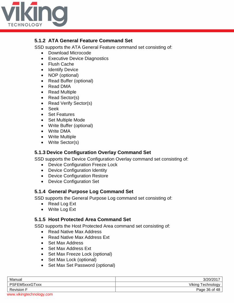
5.1 ATA Commands 34 5.1.1 48-Bit Address Command Set 35 5.1.2 ATA General Feature Command Set 36 5.1.3 Device Configuration Overlay Command Set 36 5.1.4 General Purpose Log Command Set 36 5.1.5 Host Protected Area Command Set 36 5.1.6 Power Management Command Set 37 5.1.7 Security Mode Feature Set 37 5.1.8 Identify Device Data 38 5.1.1 S.M.A.R.T. Support 42 5.1.2 SATA 3.0 S.M.A.R.T. Command Set 43
5.2 SATA Commands 47 5.2.1 Native Command Queuing (NCQ) 47
6 REFERENCES 47
7 GLOSSARY 48
Manual 3/20/2017
PSFEM5xxxGTxxx Viking Technology
Revision F Page 9 of 48
www.vikingtechnology.com
Table of Tables Table 2-1: Maximum Sustained Read and Write Bandwidth ____________________________ 13 Table 2-2: Random Read and Write Input/Output Operations per Second (IOPS) ___________ 13 Table 2-3: Timing Specifications _________________________________________________ 13 Table 2-4: STANDBY IMMEDIATE Timing _________________________________________ 14 Table 2-5: Absolute Maximum Ratings ____________________________________________ 14 Table 2-6: Operating Voltage ____________________________________________________ 14 Table 2-7: Typical Power Consumption at 3.3V ______________________________________ 15 Table 2-8: Temperature and Altitude Related Specifications ____________________________ 15 Table 2-9: Shock and Vibration Specifications _______________________________________ 16 Table 2-10: Reliability Specifications ______________________________________________ 16 Table 2-11: Military Secure Erase / Sanitize Routines _________________________________ 18 Table 3-1: M.2 SSD weight ______________________________________________________ 33 Table 4-1: M.2 SATA Connector Pinouts ___________________________________________ 33 Table 5-1: Supported ATA Commands ____________________________________________ 34 Table 5-2: List of Device Identification _____________________________________________ 38 Table 5-3: S.M.A.R.T. Command Set ______________________________________________ 43 Table 5-4: Extended SMART Attribute Table ________________________________________ 43 Table 5-5: Extended SMART Attribute Actual Data ___________________________________ 44 Table 5-6: Supported S.M.A.R.T. EXECUTE OFF-LINE IMMEDIATE Subcommands ________ 47
Table of Figures Figure 1-1: High-Level Block Diagram _____________________________________________ 11 Figure 3-1: Dimensions ________________________________________________________ 29 Figure 3-2: Dimension Details for M.2 80mm length __________________________________ 30 Figure 3-3: Dimension Details for M.2 card edge _____________________________________ 31 Figure 3-4: Dimension Details for M.2 connector and notch ____________________________ 32
Manual 3/20/2017
PSFEM5xxxGTxxx Viking Technology
Revision F Page 10 of 48
www.vikingtechnology.com
1 Introduction Viking’s rugged industrial designed SSD’s offer the highest flash storage reliability and performance in harsh environments such as shock, vibration, humidity, altitude, ESD, and extreme temperatures.
1.1 Features
The SSD delivers the following features:
Seamless SATA Revision 3.2 interface support for SATA up to 6Gb/s
Low overall SSD power consumption
Supports Native Command Queuing (NCQ) to 32 commands
Compatible with all major SLC and MLC flash technologies
S.M.A.R.T.
Superior static and dynamic wear-leveling algorithm
Efficient error recovery
Power hold-up circuit technology ensures no data loss resulting from an unexpected power loss and is supported for industrial temperatures
TRIM Support
48-bit LBA Support
Manual 3/20/2017
PSFEM5xxxGTxxx Viking Technology
Revision F Page 11 of 48
www.vikingtechnology.com
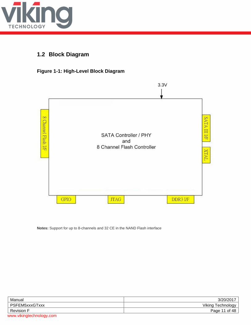
1.2 Block Diagram
Figure 1-1: High-Level Block Diagram
Notes: Support for up to 8-channels and 32 CE in the NAND Flash interface
3.3V
Manual 3/20/2017
PSFEM5xxxGTxxx Viking Technology
Revision F Page 12 of 48
www.vikingtechnology.com
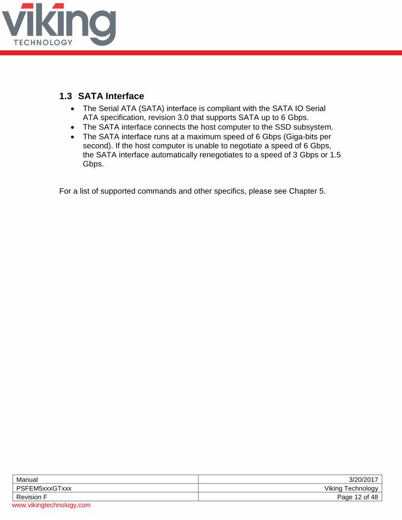
1.3 SATA Interface
The Serial ATA (SATA) interface is compliant with the SATA IO Serial ATA specification, revision 3.0 that supports SATA up to 6 Gbps.
The SATA interface connects the host computer to the SSD subsystem.
The SATA interface runs at a maximum speed of 6 Gbps (Giga-bits per second). If the host computer is unable to negotiate a speed of 6 Gbps, the SATA interface automatically renegotiates to a speed of 3 Gbps or 1.5 Gbps.
For a list of supported commands and other specifics, please see Chapter 5.
Manual 3/20/2017
PSFEM5xxxGTxxx Viking Technology
Revision F Page 13 of 48
www.vikingtechnology.com
2 Product Specifications
2.1 Performance
Table 2-1: Maximum Sustained Read and Write Bandwidth
Access Type MB/s
Sequential Read, 256K Up to 550
Sequential Write, 256K Up to 530 Notes:
1. Performance measured using Iometer 08 2. Performance may vary from flash configuration, SDR configuration, and platform. 3. Refer to Application Note AN0006 for Viking SSD Benchmarking Methodology. 4. Data is based on SSD’s using Toshiba A19nm Toggle NAND devices
Table 2-2: Random Read and Write Input/Output Operations per Second (IOPS)
Access Type IOPS
Read, 4K Up to 100,000
Write, 4K Up to 90,000 Notes:
1. Performance measured using Iometer 08 with queue depth set to 32. 2. Write Cache enabled with DDR cache. 3. Random IOPS cover the entire range of legal logical block addresses (LBA’s). Measurements are
performed on a full drive (all LBA’s have valid content). 4. Performance may vary by NAND type and host. 5. Refer to Application Note AN0006 for Viking SSD Benchmarking Methodology. 6. Data is based on SSD’s using Toshiba A19nm NAND devices
2.2 Timing
Table 2-3: Timing Specifications
Type Average Latency
Read (at 64KB) 0.14mS
Write (at 64KB) 2.12mS
Power On Ready (POR) 436mS
Notes:
1. Device measured using Drivemaster. 2. DRQ (Data Transfer Requested) bit being asserted
2.2.1 STANDBY IMMEDIATE Command
The Power-On-to-Ready time assumes a proper shutdown (power removal preceded by STANDBY IMMEDIATE command. A STANDBY IMMEDIATE before power down always performs a graceful shutdown and does not require the use of the hold-up circuit.
Manual 3/20/2017
PSFEM5xxxGTxxx Viking Technology
Revision F Page 14 of 48
www.vikingtechnology.com
Table 2-4: STANDBY IMMEDIATE Timing
Power Cycle Endurance Min Max Unit
STANDBY IMMEDIATE to WE completed - 72.9 ms Notes:
1. From Standby Immediate command to NAND Write Protect enable.
2.3 Electrical Characteristics
2.3.1 Absolute Maximum Ratings
Values shown are stress ratings only. Functional operation outside normal operating values is not implied. Extended exposure to absolute maximum ratings may affect reliability.
Table 2-5: Absolute Maximum Ratings
Description Min Max Unit
Maximum Voltage Range for Vin -0.2 3.6 V
Maximum Temperature Range -40 85 c
2.3.2 Supply Voltage
The operating voltage is 3.3V
Table 2-6: Operating Voltage
Description Min Max Unit
Operating Voltage for 3.3 V (+/- 5%) 3.135 3.465 V
Manual 3/20/2017
PSFEM5xxxGTxxx Viking Technology
Revision F Page 15 of 48
www.vikingtechnology.com
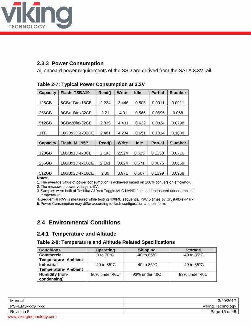
2.3.3 Power Consumption
All onboard power requirements of the SSD are derived from the SATA 3.3V rail.
512GB 16GBx2Diex16CE 2.39 3.971 0.567 0.1199 0.0968 Notes: 1. The average value of power consumption is achieved based on 100% conversion efficiency. 2. The measured power voltage is 5V. 3. Samples were built of Toshiba A19nm Toggle MLC NAND flash and measured under ambient
temperature. 4. Sequential R/W is measured while testing 400MB sequential R/W 5 times by CrystalDiskMark. 5. Power Consumption may differ according to flash configuration and platform.
2.4 Environmental Conditions
2.4.1 Temperature and Altitude
Table 2-8: Temperature and Altitude Related Specifications
Conditions Operating Shipping Storage
Commercial Temperature- Ambient
0 to 70°C
-40 to 85°C
-40 to 85°C
Industrial Temperature- Ambient
-40 to 85°C
-40 to 85°C
-40 to 85°C
Humidity (non-condensing)
90% under 40C 93% under 40C 93% under 40C
Manual 3/20/2017
PSFEM5xxxGTxxx Viking Technology
Revision F Page 16 of 48
www.vikingtechnology.com
2.4.2 Shock and Vibration
SSD products are tested in accordance with environmental specification for shock and vibration
Table 2-9: Shock and Vibration Specifications
Stimulus Description
Shock 500G, 2ms
Vibration 20 – 80 Hz/1.52mm 80 – 2000 Hz/20G
(X,Y,Z axis / 30 min for each)
2.4.3 Electromagnetic Immunity
M.2 is an embedded product for host systems and is designed not to impair with system functionality or hinder system EMI/FCC compliance.
2.5 Reliability
Table 2-10: Reliability Specifications
Parameter Description
ECC 120 bit per 2KB page
Read Endurance
Unlimited
Write Endurance
32GB 64GB 128GB 256GB 512GB 1024GB
79 TBW 158 TBW 317 TBW 635 TBW 1272 TBW 2548 TBW
Data retention > 90 days at NAND expiration
2.6 Data Security
2.6.1 Encryption
The SSD drive is a self-encrypting drive (SED), with a bulk data encryption feature that provides automatic hardware-based data security and enhanced secure erase capability. A self-encrypting drives, scrambles data using a data encryption key as it is written to the drive and then descrambles it with the key as it is retrieved. This gives the user the highest level of data protection available and provides a fast
Manual 3/20/2017
PSFEM5xxxGTxxx Viking Technology
Revision F Page 17 of 48
www.vikingtechnology.com
erase simply by deleting the encryption key, eliminating the need for time consuming data-overwrite. Data on the drive is instantly rendered unreadable. The SSD supports AES-256 encryption and ATA Secure Erase features to protect sensitive data. The SSD drives support the following security features:
AES 256 on the fly support.
RSA 512/1024/2048
SHA 160/256/512
TCG OPAL SSC V1.0
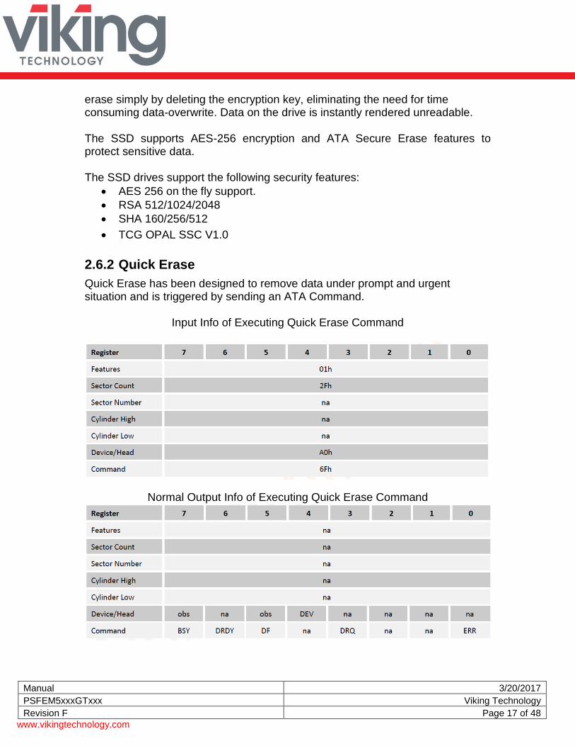
2.6.2 Quick Erase
Quick Erase has been designed to remove data under prompt and urgent situation and is triggered by sending an ATA Command.
Input Info of Executing Quick Erase Command
Normal Output Info of Executing Quick Erase Command
Manual 3/20/2017
PSFEM5xxxGTxxx Viking Technology
Revision F Page 18 of 48
www.vikingtechnology.com
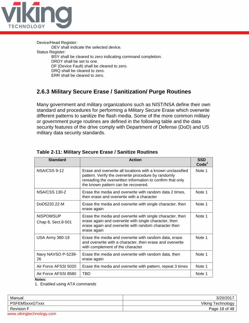
Device/Head Register: DEV shall indicate the selected device.
Status Register: BSY shall be cleared to zero indicating command completion. DRDY shall be set to one. DF (Device Fault) shall be cleared to zero. DRQ shall be cleared to zero. ERR shall be cleared to zero.
2.6.3 Military Secure Erase / Sanitization/ Purge Routines
Many government and military organizations such as NIST/NSA define their own standard and procedures for performing a Military Secure Erase which overwrite different patterns to sanitize the flash media. Some of the more common military or government purge routines are defined in the following table and the data security features of the drive comply with Department of Defense (DoD) and US military data security standards.
Table 2-11: Military Secure Erase / Sanitize Routines
Standard Action SSD Code
1
NSA/CSS 9-12 Erase and overwrite all locations with a known unclassified pattern. Verify the overwrite procedure by randomly rereading the overwritten information to confirm that only the known pattern can be recovered.
Note 1
NSA/CSS 130-2 Erase the media and overwrite with random data 2 times, then erase and overwrite with a character
Note 1
DoD5220.22-M Erase the media and overwrite with single character, then erase again
Note 1
NISPOMSUP
Chap 8, Sect.8-501
Erase the media and overwrite with single character, then erase again and overwrite with single character, then erase again and overwrite with random character then erase again
Note 1
USA Army 380-19 Erase the media and overwrite with random data, erase and overwrite with a character, then erase and overwrite with complement of the character
Note 1
Navy NAVSO P-5239-26
Erase the media and overwrite with random data, then erase again
Note 1
Air Force AFSSI 5020 Erase the media and overwrite with pattern, repeat 3 times Note 1
Air Force AFSSI 8580 TBD Note 1
Notes:
1. Enabled using ATA commands
Manual 3/20/2017
PSFEM5xxxGTxxx Viking Technology
Revision F Page 19 of 48
www.vikingtechnology.com
Manual 3/20/2017
PSFEM5xxxGTxxx Viking Technology
Revision F Page 20 of 48
www.vikingtechnology.com
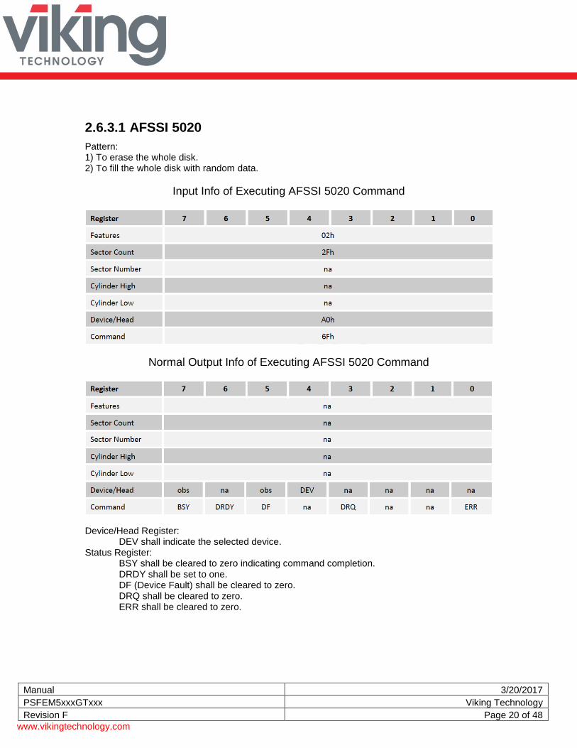
2.6.3.1 AFSSI 5020
Pattern: 1) To erase the whole disk. 2) To fill the whole disk with random data.
Input Info of Executing AFSSI 5020 Command
Normal Output Info of Executing AFSSI 5020 Command
Device/Head Register:
DEV shall indicate the selected device. Status Register:
BSY shall be cleared to zero indicating command completion. DRDY shall be set to one. DF (Device Fault) shall be cleared to zero. DRQ shall be cleared to zero. ERR shall be cleared to zero.
Manual 3/20/2017
PSFEM5xxxGTxxx Viking Technology
Revision F Page 21 of 48
www.vikingtechnology.com
2.6.3.2 DOD 5220.22-M
Pattern: 1) To fill the whole disk with fixed character pattern of 0x55. 2) To erase the whole disk.
Input Info of Executing DoD 5220.22-M Command
Normal Output Info of Executing DoD 5220.22-M Command
Device/Head Register:
DEV shall indicate the selected device. Status Register:
BSY shall be cleared to zero indicating command completion. DRDY shall be set to one. DF (Device Fault) shall be cleared to zero. DRQ shall be cleared to zero. ERR shall be cleared to zero.
Manual 3/20/2017
PSFEM5xxxGTxxx Viking Technology
Revision F Page 22 of 48
www.vikingtechnology.com
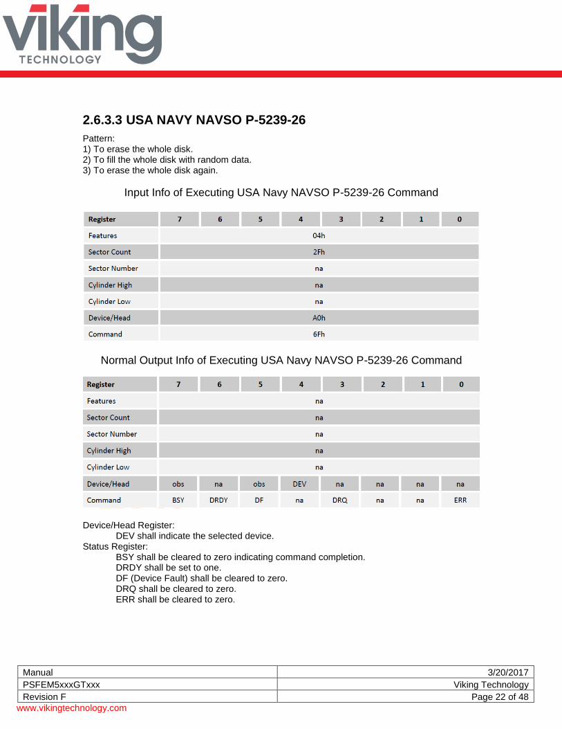
2.6.3.3 USA NAVY NAVSO P-5239-26
Pattern: 1) To erase the whole disk. 2) To fill the whole disk with random data. 3) To erase the whole disk again.
Input Info of Executing USA Navy NAVSO P-5239-26 Command
Normal Output Info of Executing USA Navy NAVSO P-5239-26 Command
Device/Head Register:
DEV shall indicate the selected device. Status Register:
BSY shall be cleared to zero indicating command completion. DRDY shall be set to one. DF (Device Fault) shall be cleared to zero. DRQ shall be cleared to zero. ERR shall be cleared to zero.
Manual 3/20/2017
PSFEM5xxxGTxxx Viking Technology
Revision F Page 23 of 48
www.vikingtechnology.com
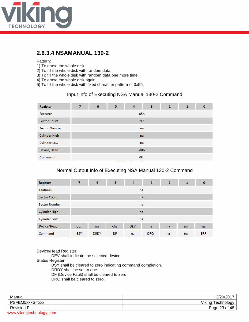
2.6.3.4 NSAMANUAL 130-2
Pattern: 1) To erase the whole disk. 2) To fill the whole disk with random data. 3) To fill the whole disk with random data one more time. 4) To erase the whole disk again. 5) To fill the whole disk with fixed character pattern of 0x55.
Input Info of Executing NSA Manual 130-2 Command
Normal Output Info of Executing NSA Manual 130-2 Command
Device/Head Register:
DEV shall indicate the selected device. Status Register:
BSY shall be cleared to zero indicating command completion. DRDY shall be set to one. DF (Device Fault) shall be cleared to zero. DRQ shall be cleared to zero.
Manual 3/20/2017
PSFEM5xxxGTxxx Viking Technology
Revision F Page 24 of 48
www.vikingtechnology.com
ERR shall be cleared to zero.
Manual 3/20/2017
PSFEM5xxxGTxxx Viking Technology
Revision F Page 25 of 48
www.vikingtechnology.com
2.6.3.5 USA-ARMY 380-19
Pattern: 1) To erase the whole disk. 2) To fill the whole disk with random data. 3) To fill the whole disk with fixed character pattern of 0x55. 4) To fill the whole disk with fixed character pattern of 0xAA.
Input Info of Executing USA-Army 380-19 Command
Normal Output Info of Executing USA-Army 380-19 Command
Device/Head Register:
DEV shall indicate the selected device. Status Register:
BSY shall be cleared to zero indicating command completion. DRDY shall be set to one. DF (Device Fault) shall be cleared to zero. DRQ shall be cleared to zero. ERR shall be cleared to zero.
Manual 3/20/2017
PSFEM5xxxGTxxx Viking Technology
Revision F Page 26 of 48
www.vikingtechnology.com
2.6.3.6 NISPOMSUP CHAP 8, SECT. 8-501
Pattern: 1) To fill the whole disk with fixed character pattern of 0x55. 2) To fill the whole disk with fixed character pattern of 0xAA. 3) To fill the whole disk with random data.
Input Info of Executing NISPOMSUP chap 8, Sect. 8-501 Command
Normal Output Info of Executing NISPOMSUP chap 8, Sect. 8-501 Command
Device/Head Register:
DEV shall indicate the selected device. Status Register:
BSY shall be cleared to zero indicating command completion. DRDY shall be set to one. DF (Device Fault) shall be cleared to zero. DRQ shall be cleared to zero. ERR shall be cleared to zero.
Manual 3/20/2017
PSFEM5xxxGTxxx Viking Technology
Revision F Page 27 of 48
www.vikingtechnology.com
2.6.3.7 NSA/CSS 9-12
Pattern: 1) To fill the whole disk with fixed character pattern of 0x55.
Input Info of Executing NSA/CSS 9-12 Command
Normal Output Info of Executing NSA/CSS 9-12 Command
Device/Head Register:
DEV shall indicate the selected device. Status Register:
BSY shall be cleared to zero indicating command completion. DRDY shall be set to one. DF (Device Fault) shall be cleared to zero. DRQ shall be cleared to zero. ERR shall be cleared to zero.
Manual 3/20/2017
PSFEM5xxxGTxxx Viking Technology
Revision F Page 28 of 48
www.vikingtechnology.com
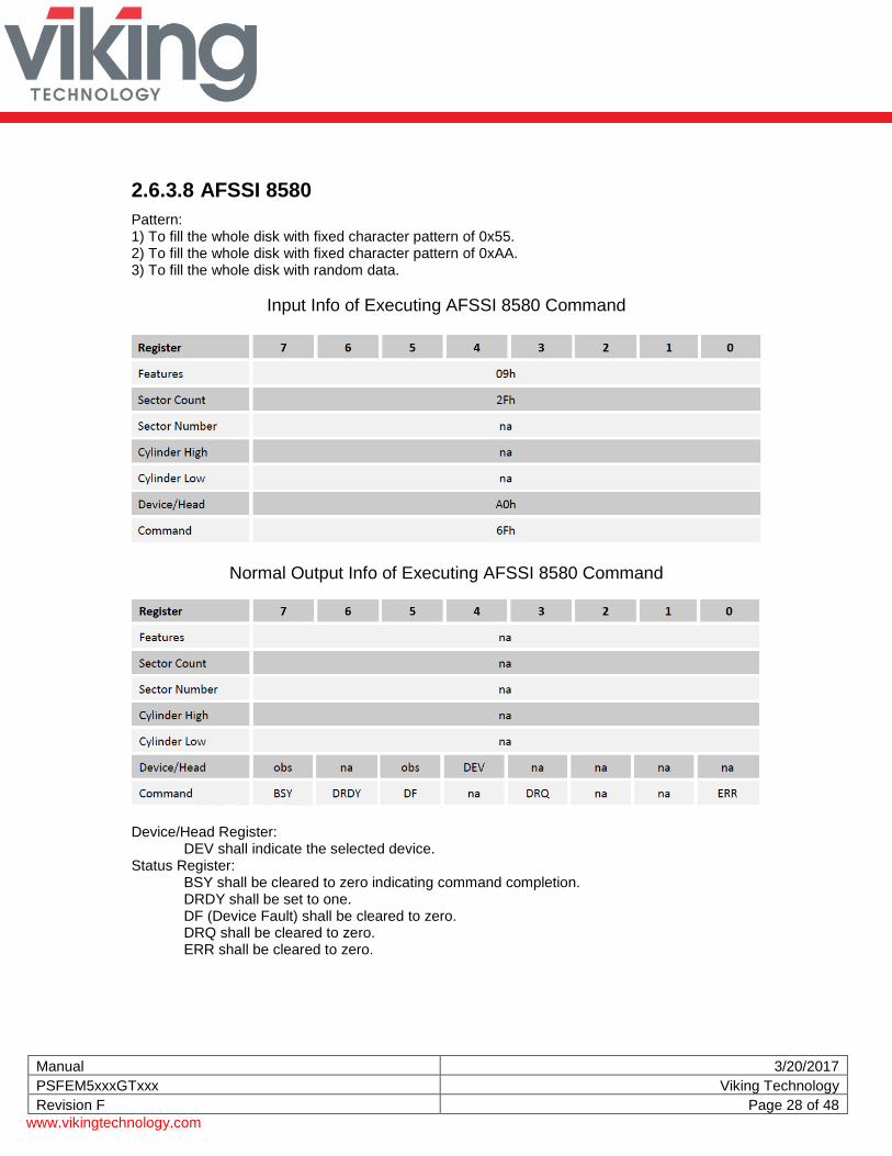
2.6.3.8 AFSSI 8580
Pattern: 1) To fill the whole disk with fixed character pattern of 0x55. 2) To fill the whole disk with fixed character pattern of 0xAA. 3) To fill the whole disk with random data.
Input Info of Executing AFSSI 8580 Command
Normal Output Info of Executing AFSSI 8580 Command
Device/Head Register:
DEV shall indicate the selected device. Status Register:
BSY shall be cleared to zero indicating command completion. DRDY shall be set to one. DF (Device Fault) shall be cleared to zero. DRQ shall be cleared to zero. ERR shall be cleared to zero.
Manual 3/20/2017
PSFEM5xxxGTxxx Viking Technology
Revision F Page 29 of 48
www.vikingtechnology.com
3 Mechanical Information
3.1 Dimensions
Figure 3-1: Dimensions
d
Notes:
1. All dimensions are in millimeter. General tolerance is ± 0.15. PCB thickness 0.8 ± 0.08 2. Refer to Ordering Information table for the complete Viking part number that describes the “xxx”.
VRFEM6xxxNote2
VRFEM4xxxNote2
VPFEM5xxx Note2
Manual 3/20/2017
PSFEM5xxxGTxxx Viking Technology
Revision F Page 30 of 48
www.vikingtechnology.com
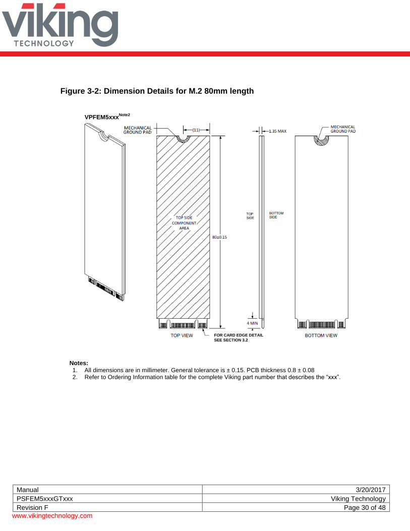
Figure 3-2: Dimension Details for M.2 80mm length
Notes:
1. All dimensions are in millimeter. General tolerance is ± 0.15. PCB thickness 0.8 ± 0.08 2. Refer to Ordering Information table for the complete Viking part number that describes the “xxx”.
FOR CARD EDGE DETAIL
SEE SECTION 3.2
VPFEM5xxxNote2
Manual 3/20/2017
PSFEM5xxxGTxxx Viking Technology
Revision F Page 31 of 48
www.vikingtechnology.com
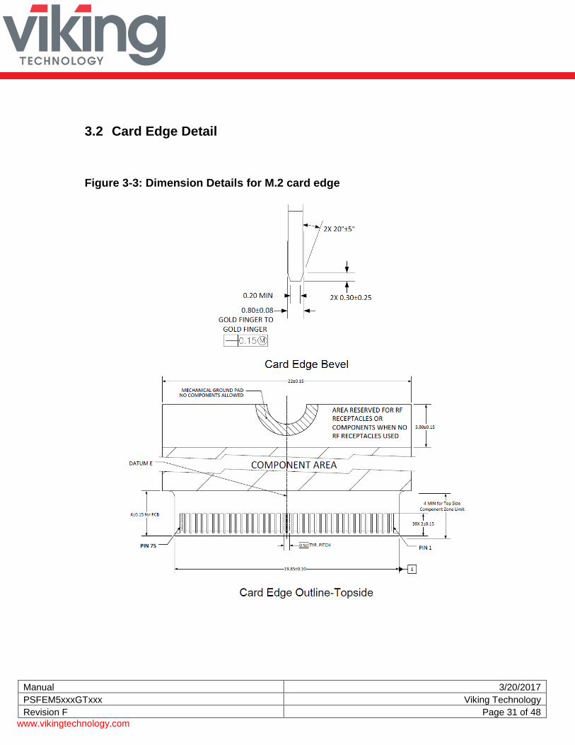
3.2 Card Edge Detail
Figure 3-3: Dimension Details for M.2 card edge
Manual 3/20/2017
PSFEM5xxxGTxxx Viking Technology
Revision F Page 32 of 48
www.vikingtechnology.com
Figure 3-4: Dimension Details for M.2 connector and notch
Key notch detail
Manual 3/20/2017
PSFEM5xxxGTxxx Viking Technology
Revision F Page 33 of 48
www.vikingtechnology.com
3.3 M.2 SSD Weight
Table 3-1: M.2 SSD weight
Length Weight Unit of measure
80 mm < 8 Grams
4 Pin and Signal Descriptions
4.1 Signal and Power Description Tables
Table 4-1: M.2 SATA Connector Pinouts
Pin Description Description Pin
74 3.3V CONFIG_2 = GND 75
72 3.3V GND 73
70 3.3V GND 71
68 SUSCLK(32kHz) (I)(0/3.3V) CONFIG_1 = GND 69
66 Module Key N/C 67
64 Module Key Module Key 65
62 Module Key Module Key 63
60 Module Key Module Key 61
58 Reserved for MFG_CLOCK Module Key 59
56 Reserved for MFG_DATA GND 57
54 N/C N/C 55
52 N/C N/C 53
50 N/C GND 51
48 N/C SATA-A+ 49
46 N/C SATA-A- 47
44 N/C GND 45
42 N/C SATA-B- 43
40 N/C SATA-B+ 41
38 DEVSLP (I)(0/3.3V) GND 39
36 N/C N/C 37
34 N/C N/C 35
32 N/C GND 33
30 N/C N/C 31
28 N/C N/C 29
26 N/C GND 27
Manual 3/20/2017
PSFEM5xxxGTxxx Viking Technology
Revision F Page 34 of 48
www.vikingtechnology.com
Pin Description Description Pin
24 N/C N/C 25
22 N/C N/C 23
20 N/C CONFIG_0 = GND 21
18 Module Key Module Key 19
16 Module Key Module Key 17
14 Module Key Module Key 15
12 Module Key Module Key 13
10 DAS/DSS# (I/O) N/C 11
8 N/C N/C 9
6 N/C N/C 7
4 3.3V N/C 5
2 3.3V GND 3
CONFIG_3 = GND 1 Notes:
1. No connect on the host side. 2. Socket-2 SATA-based SSD Module pinout per PCI Express M.2 Specification, Revision 1.0 (p134)
4.2 Hot Plug Support
Hot Plug insertion and removal are supported in the presence of a proper connector and appropriate operating system (OS) support as described in the SATA 2.6 specification. This product supports Asynchronous Signal Recovery and will issue an unsolicited COMINIT when first mated with a powered connector to guarantee reliable detection by a host system without hardware device detection.
5 Command Sets
5.1 ATA Commands
Table 5-1: Supported ATA Commands
Description Op Code
Description Op Code
Check power mode E5h Security Disable Password F6h
Data Set management 06h Security Erase Prepare F3h
DCO B1h Security Erase Unit F4h
Download Microcode PIO 92h Security Freeze Lock F5h
Download Microcode DMA 93h Security Set Password F1h
Execute drive diagnostic 90h Security Unlock F2h
Flush cache E7h Seek 70h
Manual 3/20/2017
PSFEM5xxxGTxxx Viking Technology
Revision F Page 35 of 48
www.vikingtechnology.com
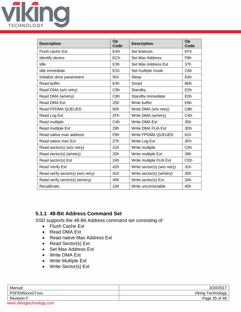
Description Op Code
Description Op Code
Flush cache Ext EAh Set features EFh
Identify device ECh Set Max Address F9h
Idle E3h Set Max Address Ext 37h
Idle immediate E1h Set multiple mode C6h
Initialize drive parameters 91h Sleep E6h
Read buffer E4h Smart B0h
Read DMA (w/o retry) C9h Standby E2h
Read DMA (w/retry) C8h Standby immediate E0h
Read DMA Ext 25h Write buffer E8h
Read FPDMA QUEUED 60h Write DMA (w/o retry) CBh
Read Log Ext 2Fh Write DMA (w/retry) CAh
Read multiple C4h Write DMA Ext 35h
Read multiple Ext 29h Write DMA FUA Ext 3Dh
Read native max address F8h Write FPDMA QUEUED 61h
Data storage drives capture a variety of information during operation that may be used to analyze drive ―health. SATA drives provide Self-Monitoring, Analysis and Reporting Technology (SMART) features that include monitoring and storing critical performance and calibration parameters to attempt to predict the likelihood of near-term degradation or fault conditions. Drive manufacturers have adopted S.M.A.R.T. to help warn system software, a system administrator, or a user of impending drive failure, while time remains to take preventive action. It provides the host system with the knowledge of a negative reliability condition to allow the host system to warn the user of the impending risk of data loss and advise the user of the appropriate action. The technical documentation for S.M.A.R.T. is captured in the AT Attachment (ATA) standard. The standard defines the protocols for reporting errors and for invoking self-tests to collect and analyze data on demand. The ATA specification is flexible and provides for individual manufacturers to define their own unique vendor specific information. This section describes the baseline supported S.M.A.R.T. command attributes. The information herein should be used in conjunction with the ATA standard and related documents, which may serve as references for topics and details not addressed here. Further, it is recommended to consult the list of public S.M.A.R.T. attributes. See the AT Attachment standard for implementation details.
Manual 3/20/2017
PSFEM5xxxGTxxx Viking Technology
Revision F Page 43 of 48
www.vikingtechnology.com
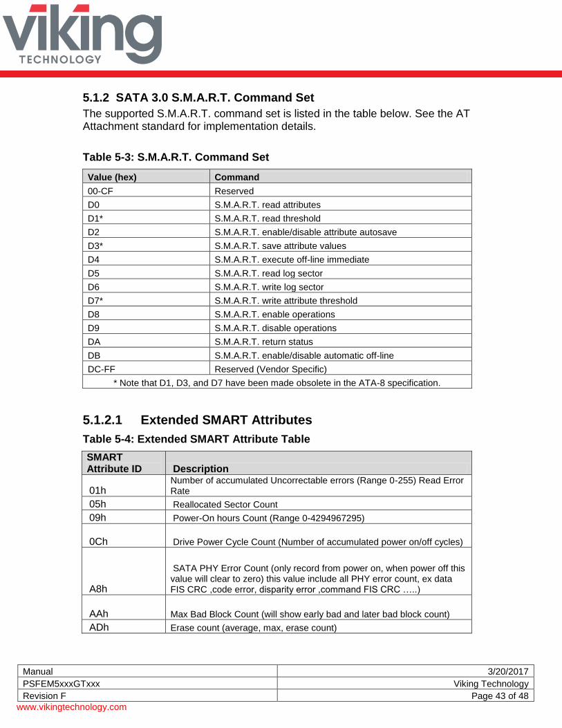
5.1.2 SATA 3.0 S.M.A.R.T. Command Set
The supported S.M.A.R.T. command set is listed in the table below. See the AT Attachment standard for implementation details.
Table 5-3: S.M.A.R.T. Command Set
Value (hex) Command
00-CF Reserved
D0 S.M.A.R.T. read attributes
D1* S.M.A.R.T. read threshold
D2 S.M.A.R.T. enable/disable attribute autosave
D3* S.M.A.R.T. save attribute values
D4 S.M.A.R.T. execute off-line immediate
D5 S.M.A.R.T. read log sector
D6 S.M.A.R.T. write log sector
D7* S.M.A.R.T. write attribute threshold
D8 S.M.A.R.T. enable operations
D9 S.M.A.R.T. disable operations
DA S.M.A.R.T. return status
DB S.M.A.R.T. enable/disable automatic off-line
DC-FF Reserved (Vendor Specific)
* Note that D1, D3, and D7 have been made obsolete in the ATA-8 specification.
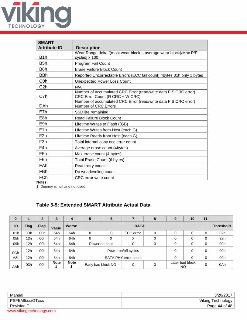
5.1.2.1 Extended SMART Attributes
Table 5-4: Extended SMART Attribute Table
SMART Attribute ID Description
01h Number of accumulated Uncorrectable errors (Range 0-255) Read Error Rate
05h Reallocated Sector Count
09h Power-On hours Count (Range 0-4294967295)
0Ch Drive Power Cycle Count (Number of accumulated power on/off cycles)
A8h
SATA PHY Error Count (only record from power on, when power off this value will clear to zero) this value include all PHY error count, ex data FIS CRC ,code error, disparity error ,command FIS CRC …..)
AAh Max Bad Block Count (will show early bad and later bad block count)
ADh Erase count (average, max, erase count)
Manual 3/20/2017
PSFEM5xxxGTxxx Viking Technology
Revision F Page 44 of 48
www.vikingtechnology.com
SMART Attribute ID Description
B1h Wear Range delta [(most wear block – average wear block)/Max P/E cycles] x 100
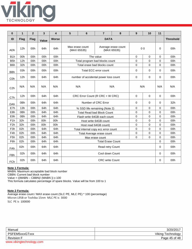
F4h 02h 00h 64h 64h Total Average erase count 0 0 0 00h
F5h 02h 00h 64h 64h Max erase count 0 0 0 00h
F6h 02h 00h 64h 64h Total Erase Count 0 00h
FAh
02h 00h 64h 64h Read retry Count 0 00h
FBh
02h 00h 64h 64h Cool down Count 0 00h
FCh
02h 00h 64h 64h CRC write Count 0 00h
Note 1 Formula:
MABN: Maximum acceptable bad block number CBBN: Current bad block number Value = ((MABN – CBBN)/ (MABN )) x 100 This formula calculates percentage of spare blocks. Value will be from 100 to 1 Note 2 Formula:
Average erase count / MAX erase count (SLC PE, MLC PE) * 100 (percentage)
Micron L95B or Toshiba 15nm MLC PE is 3000 SLC PE is 100000
Manual 3/20/2017
PSFEM5xxxGTxxx Viking Technology
Revision F Page 46 of 48
www.vikingtechnology.com
5.1.2.2 Off-line Mode
SSD’s support the optional 28-bit S.M.A.R.T. EXECUTION OFF-LINE IMMEDIATE (B0h/D4h) command per the ATA-8 specification. This command causes the SSD to initiate the collection of S.M.A.R.T. data in an off-line mode and then preserves this data across power and reset events. Supported subcommands include those shown in the table below. Reference the ATA-8 specification for subcommand detail.
00h Execute S.M.A.R.T. off-line routine immediately in off-line mode
01h Execute S.M.A.R.T. Short self-test routine immediately in off-line mode
02h Execute S.M.A.R.T. Extended self-test routine immediately in off-line mode
04h Execute S.M.A.R.T. Selective self-test routine immediately in off-line mode
7Fh Abort off-line mode self-test routine
81h Execute S.M.A.R.T. Short self-test routine immediately in captive mode
82h Execute S.M.A.R.T. Extended self-test routine immediately in captive mode
84h Execute S.M.A.R.T. Selective self-test routine immediately in captive mode
5.2 SATA Commands
The SATA 2.6 specification is a super set of the ATA/ATAPI-7 specification with regard to supported commands. SSD’s support the following features that are unique to the SATA specification.
5.2.1 Native Command Queuing (NCQ)
SSD’s support the Native Command Queuing (NCQ) command set, which consists of
READ FPDMA QUEUED
WRITE FPDMA QUEUED Note: With a maximum queue depth less than or equal to 32.
6 References Serial ATA Specification, Revision 3
PCI Express M.2 Specification, Revision 1.0
Manual 3/20/2017
PSFEM5xxxGTxxx Viking Technology
Revision F Page 48 of 48
www.vikingtechnology.com
7 Glossary This document incorporates many industry and device-specific words. Use the following list to define a variety of terms and acronyms. Term Definition
BER Bit error rate, or percentage of bits that have errors relative to the total number of bits received
DIPM Device Initiated Link Power Management. The ability of the device to request SATA link power state changes.
DMA Direct Memory Access
eMLC Enterprise Multi-Level Cell
EXT Extended
FP First Party
GB Giga-byte defined as 1x109 bytes
HDD Hard Disk Drive
Hot Plug A term used to describe the removal or insertion of a SATA storage drive when the system is powered on.
IOPS Input output operations per second
LBA Logical Block Address
MB Mega-bytes defined as 1x106 bytes
MLC Multi-Level Cell
MTBF Mean Time Between Failures
NCQ Native Command Queuing. The ability of the SATA hard drive to queue and re-order commands to maximize execution efficiency.
NOP No Operation
OS Operating System
Port The point at which a SATA drive physically connects to the SATA controller.
RMS Root Mean Squared
RPM Revolutions Per Minute
SAS Serial Attached SCSI
SATA Serial ATA
SFF Small Form Factor
SLC Single Level Cell
S.M.A.R.T.
Self-Monitoring, Analysis and Reporting Technology: an open standard for developing hard drives and software systems that automatically monitors a hard drive’s health and reports potential problems.